EP4073500B1 - Verfahren und steuergerät zum bestimmen eines messstromwertes einer breitband-lambdasonde - Google Patents
Verfahren und steuergerät zum bestimmen eines messstromwertes einer breitband-lambdasonde Download PDFInfo
- Publication number
- EP4073500B1 EP4073500B1 EP20821170.6A EP20821170A EP4073500B1 EP 4073500 B1 EP4073500 B1 EP 4073500B1 EP 20821170 A EP20821170 A EP 20821170A EP 4073500 B1 EP4073500 B1 EP 4073500B1
- Authority
- EP
- European Patent Office
- Prior art keywords
- value
- pump current
- pump
- measurement
- dac
- Prior art date
- Legal status (The legal status is an assumption and is not a legal conclusion. Google has not performed a legal analysis and makes no representation as to the accuracy of the status listed.)
- Active
Links
Images


Classifications
-
- G—PHYSICS
- G01—MEASURING; TESTING
- G01N—INVESTIGATING OR ANALYSING MATERIALS BY DETERMINING THEIR CHEMICAL OR PHYSICAL PROPERTIES
- G01N27/00—Investigating or analysing materials by the use of electric, electrochemical, or magnetic means
- G01N27/26—Investigating or analysing materials by the use of electric, electrochemical, or magnetic means by investigating electrochemical variables; by using electrolysis or electrophoresis
- G01N27/416—Systems
- G01N27/417—Systems using cells, i.e. more than one cell and probes with solid electrolytes
- G01N27/4175—Calibrating or checking the analyser
Definitions
- the present invention relates to a method for determining a measuring current value of a broadband lambda sensor according to the preamble of claim 1 and a control device set up for this purpose according to the preamble of the independent device claim.
- What is known in particular is a method for determining a measuring current value of a broadband lambda sensor which has a Nernst cell and a pump cell, wherein a potential difference that occurs across the Nernst cell is detected and processed by a pump current control circuit to form a pump current control value, from which a controllable current source is formed real pump current is generated, which is supplied to the pump cell at a pump electrode, and wherein a measured value of the electrical current flowing out of a counter electrode of the pump cell is recorded as a pump current measured value.
- Broadband lambda sensors have been used in series for years and are described, for example, in the Automotive Paperback, 24th edition, 2002 on page 152. They have a sample gas volume in which, among other things, there is a sample gas component with a concentration to be measured.
- concentration of the sample gas component in the sample gas volume can be influenced by particle exchange with a sample gas reservoir, which is caused by two different effects.
- a first effect results from the fact that the measuring gas volume can exchange particles with a measuring gas reservoir to a defined, limited extent, for example via a small channel.
- the sample gas reservoir is, for example, exhaust gas from an internal combustion engine. The flow direction of the particles is always directed towards the location of the smaller concentration of the sample gas component.
- the sample gas component is, for example, oxygen.
- a second effect results from an electrical pump current with the particles of the sample gas component, for example Depending on the polarity of the electrical pump current, oxygen can be pumped from the reservoir into the sample gas volume or from the sample gas volume to the sample gas reservoir.
- the current strength of the electrical pump current is regulated so that a certain, fixed concentration of the sample gas component is established in the measuring gap, which is measured with a Nernst cell. The current strength of the electrical pump current is then a measure of the concentration of the sample gas component in the sample gas reservoir.
- this current intensity is specified by a pump current control, and on the other hand it can also be measured. Both are subject to inaccuracies.
- the specification is made, for example, by controlling a digital-analog current source with a digital pump current control value, which leads to the output of a real, analog electrical pump current with limited accuracy. Measuring the real, analog electrical pump current with an analog-to-digital converter is also of limited accuracy.
- the present invention differs from the prior art by the characterizing features of claim 1, i.e. in that the measuring current value during operation of the broadband lambda probe is determined either switchably as a function of the pump current control value or as a function of the pump current measured value.
- One advantage of current measurement is high accuracy in the upper measuring range, i.e. with larger electrical pump currents.
- the disadvantage is greater inaccuracy and sensitivity to interference with small pump currents.
- an advantage of using the pump current control value as a measuring current value is that small currents in particular can be set relatively precisely and insensitive to interference and can therefore be used as a very precise measuring current value.
- the invention is based on the new approach of using the advantages of both types of measuring current determination. What is particularly new about this approach is that the decision about which value to use can be made individually for each measuring point during ongoing operation. The decision is made based on the pump current control value. For small current measurement values, the current measurement values are determined as a function of the pump current control values, and for larger pump current measurement values, the current measurement values are determined as a function of measured pump currents.
- the combination of the two types of determination of the measuring current value has the following further advantage: An associated current measurement value is available for each pump current control value.
- the respective "individual" principles of current setting and current measuring have the disadvantage that shunts to, for example, vehicle ground cannot be detected at the respective pump current pin or current measuring pin.
- a preferred embodiment is characterized in that the function is the identity, so that the measuring current value during operation of the broadband lambda probe is selectively determined as the pump current control value or as the pump current measured value.
- the pump current control value is compared with a pump current control value threshold value, and that the pump current control value is determined as a measuring current value if the pump current control value is smaller than the pump current control value threshold value, and that the pump current measurement value is determined as a measurement current value if the pump current control value is greater than the pump current control value threshold value.
- the function is an averaging in which an average deviation of the pump current measurement value is formed from the pump current control value and that the average deviation is subtracted from the pump current control value when the measurement current value is formed as the pump current control value and that the measurement current value is used as that The result of the subtraction is determined.
- a further preferred embodiment is characterized in that the pump current measurement value is converted into a digital pump current measurement value using an analog-digital converter and that the measurement current value in an operating phase of the broadband lambda sensor, in which the analog-digital converter is calibrated, as the Pump current control value is determined.
- shunts on the pump electrode i.e. on the pump current pin
- the counter electrode i.e. on the current measuring pin
- shunts on the pump electrode and on the counter electrode are determined individually and compared in order to identify the dominant shunt and that if the shunt on the counter electrode is dominant, an average deviation of the Pump current measurement value is formed by the pump current control value and that the mean deviation, when the measurement current value is formed as a function of the pump current control value, is added to the pump current control value and that the measurement current value is determined as the result of the addition.
- a further preferred embodiment is characterized in that the determined deviation is compared with a deviation threshold value and that if the deviation is greater than the deviation threshold value, an error reaction is triggered.
- the deviation is formed as a deviation of a pump current measurement value from a pump current control value output in parallel to the detection of the pump current measurement value and that the deviation threshold value is a first deviation threshold value.
- the deviation is formed as a deviation of an averaged pump current measurement value from a pump current measurement value averaged in parallel thereto and the deviation threshold value is a second deviation threshold value which is smaller than the first deviation threshold value.
- control device is set up to carry out the preferred embodiments of the method in conjunction with a broadband lambda sensor.
- Another advantage of the invention is that hardware components in the form of, for example, motor vehicle control devices are available without changes to the hardware, so that no additional costs arise. Both pump current measured values and pump current control values are also already available in the software. All that is required is an additional software threshold evaluation to decide whether the pump current control value or a measured pump current value is used for further processing.
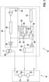
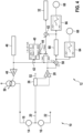
- FIG. 1 shows in detail a broadband lambda probe 10 and a control device 12.
- the broadband lambda probe 10 has a pump cell 14 and a Nernst cell 16.
- the pump cell 14 has a pump electrode 18 to be exposed to the measurement gas and a counter electrode 20 arranged in a measuring chamber/measuring gap.
- the Nernst cell 16 has a reference electrode 22 to be exposed to a reference atmosphere (for example air) and a counter electrode 20 arranged in the measuring chamber.
- the counter electrodes 20 are identical or at least connected to one another in an electrically conductive manner.
- the control device 12 has a current source control circuit 24, a measuring resistor 26, an analog-digital converter 28, a measured value switch 30 and at least one measured value user 32.
- the measured value user 32 represents, for example, a lambda control loop with which a fuel/air ratio of an internal combustion engine can be controlled.
- the measured value switch 30 has an input 34 for the pump current control value and an input 36 for the pump current measured value, a switch 38 and a switch control 40.
- the switch control 40 has an input 42 for the pump current control value and an output 44 for a switch control signal.
- the switch 38 can be switched between a first switch position and a second switch position using the switch control signal.
- the measured value user 32 is supplied with either the pumping current control value I_DAC or the pumping current measurement value I_ADC.
- the pumping current control value I_DAC is used as the measuring current value I_Mess. If the pump current control value is not smaller than a predetermined threshold value, the pump current measured value I_ADC is used as the measured current value I_Mess.
- the current source control circuit 24 has a pump current control circuit 46, a digital-to-analog converter 48 and a current source 50 that can be controlled by this. An output of the controllable current source 50 is connected to the pump electrode 18.
- the counter electrode 20 of the broadband lambda probe 10 is connected to a virtual ground 52 of the control device 12 via the measuring resistor 26.
- the pump current control circuit 46 has an input 54 which is connected to the reference electrode 22.
- the power source control circuit 24 is set up to control the digitally controllable power source 50 with a pump current control value I_DAC so that it outputs a pump current with which the concentration of a measurement gas component (in particular oxygen) in the measuring chamber/the measuring gap is adjusted.
- the concentration to be set preferably corresponds to a lambda value equal to 1.
- a typical value range for pump currents of broadband lambda sensors 10 extends from zero mA to -10 mA.
- a digital-to-analog converter 48 that has a current accuracy with a relative error of 2% and an additional absolute error of, for example, 2 ⁇ A is realistic.
- the pump current control value I_DAC can have an error of 4 ⁇ A (4%), while the pump current measurement value I_ADC can have a significantly larger error of 20 ⁇ A (20%) than the pump current control value.
- using the pump current control value as the measuring current value will provide significantly better accuracy.
- the pump current control value can have an error of 82 ⁇ A (approx. 2%); the pump current measurement value can now have a significantly smaller error of 24 ⁇ A (0.6%) than the pump current control value.
- using the pump current measurement provides significantly better accuracy.
- the pump current control value is the better measuring current value.
- the measured pump current value is the better measurement current value.
- the pump current control value and the measured pump current measurement value are comparable with each other in terms of their accuracy. They have the same level of accuracy at this current strength.
- the threshold for deciding which value is used as the measuring current value of the broadband lambda probe 10 is therefore advantageously 1mA, or is between 0.5mA and 2 mA.
- the pump current control value I_DAC is supplied to the measured value switch 30.
- the output signal I_ADC of the analog-digital converter 28, i.e. the pump current measurement value is fed to the measured value switch 30.
- the measured value switch 30 compares the pump current control value I_DAC with a predetermined pump current control value threshold value.
- the pump current control value I_DAC is smaller than the pump current control value threshold value, the pump current control value I_DAC is determined as a measurement current value and output to the measured value user 32.
- the pump current measurement value I_ADC is determined as a measurement current value and output to the measurement value user 32.
- the pumping current source is 50, as in the Figure 1 is shown, connected to the pump electrode 18 of the broadband lambda probe. If there is a shunt to vehicle ground at this connection, for example, an additional error will occur if the pump current control value is used as a measured value. The error occurs because some of the pump current output by the pump current source then flows through the shunt resistor.
- the fault currents can be determined without having to interrupt ongoing operation by forming a difference between the pump current control value I_DAC and the measured pump current I_ADC. Small deviations can be corrected and large deviations can be assessed as errors and can be used to trigger an error response, for example the display and/or storage of an error message.
- Figure 2 shows how a correction can first be carried out in the event of small deviations.
- the pump current control value I_DAC is used as the measuring current value for small pump currents, this measuring current value would be subject to an additional error of 30 ⁇ A. This also applies if only, i.e. without switching according to the invention, the pump current control value is used as a measuring current value, i.e. as an input variable for the measured value user.
- analog-digital converter 28 does not necessarily work particularly precisely in this area. Therefore, a direct correction for the difference between the target value and the measured value would only help slightly here. However, errors in the analog-digital converter 28 can be further reduced if the measurement signal is averaged or filtered over a longer period of time.
- the pump current control values I_DAC and pump current measured values I_ADC are averaged or filtered in the same way via their own paths, and then the difference between the values is formed.
- the difference is formed in Figure 2 in the link 58.
- the filtering mentioned takes place in the paths that lead directly to the link 58.
- These filters are in the Figure 2 not shown explicitly.
- the difference is first formed in a link 58 and this is then averaged or filtered in an averaging block 60. Both alternatives of averaging and difference formation are mathematically equivalent.
- the last-mentioned embodiment is in the Figure 2 shown.
- a deviation of the pump current control value I_DAC from the pump current measurement value I_ADC measured in parallel to the output of the pump current control value I_DAC is formed.
- the deviation is then averaged in an averaging block 60.
- the mean value of the deviation is then subtracted from a current pump current control value I_DAC in a link 62.
- the result of the subtraction is determined as a (corrected) measuring current value and passed on to the measured value user 32.
- the subtraction of the output value of block 60 in block 62 only takes place if the pump current control value I_DAC is supplied to the link 62 as a measuring current value. If the pump current measured value I_ADC is supplied to the link 62 as a measuring current value, this should be supplied to the measured value user 32 without subtracting the deviation.
- the shunt 56 on the pump electrode 18 usually dominates. With the correction function described up to this point, only one shunt on the pump electrode connection is corrected. A shunt on The counter electrode connection cannot be distinguished from the shunt at the pump electrode connection.
- a shunt on the counter electrode 20 cannot be corrected without additional measures, just as with the previously known method, which (only) works with a measurement of the pump current I_ADC.
- the method according to the invention is no worse than the known method and results in identical error tolerance with regard to a shunt occurring at the counter electrode 20 (systematically, however, with inverted polarity), but has the advantage of correcting a shunt 56 at the pump electrode 18.
- broadband lambda probes 10 without this “dominant” shunt 56.
- these broadband lambda probes 10 With these broadband lambda probes 10, smaller shunts can also occur at the connection of the counter electrode 56. In the known method, these shunts are not detected and produce a measurement error.
- either shunts on the pump current electrode 18 or on the counter electrode 20 can be corrected.
- the shunts at the connection of the pump electrode 18 and at the connection of the counter electrode 20 are first determined individually during the system startup. This is assumed to be known. What is new is that these shunts are compared during startup in order to identify the dominant shunt. If a shunt on the pump electrode 18 is dominant, the procedure is as described above. If, on the other hand, a shunt at the connection of the counter electrode 20 is particularly dominant, a correction value supplied to the link 62 is not subtracted, but added.
- Figure 3 illustrates a correction for shunts at both the connection of the pump electrode 18 and the connection of the counter electrode 20.
- This configuration could be used for broadband lambda probes 10 in which both shunt errors act in the same direction.
- the same direction means that, for example, the shunts to be corrected in normal operation, e.g. to vehicle ground, occur at both connections 18, 20, but not mixed in such a way that a shunt to ground occurs at one connection, while a shunt to the supply voltage occurs at the other connection occurs. This requirement applies to normal operation with acceptable shunts.
- a “specialization” or “optimization” for a shunt on the pump electrode 18 or for a shunt on the counter electrode 20 is not necessary. Undesirable effects of both shunts are equally improved.
- a disadvantage of this embodiment compared to the embodiments presented above is that the respective shunt errors are not necessarily completely corrected.
- the pump current control values I_DAC and pump current measured values I_ADC are also the subject of the Figure 3 averaged or filtered over their own paths in the same way, and then the difference between the values is formed. This is preferably done as described with reference to Figure 2 has been explained. For example, the difference is first formed in a link 58 and then averaged or filtered in an averaging block 60. Both alternatives of averaging and difference formation are mathematically equivalent. The last-mentioned embodiment is in the Figure 3 shown. There, in the link 58, a deviation of the pump current control value I_DAC from the pump current measurement value I_ADC measured in parallel to the output of the pump current control value I_DAC is formed.
- the deviation is then averaged in an averaging block 60.
- the mean value of the deviation is then halved in a halving block 61 and then in the link 62 from a current one Pump current control value I_DAC subtracted.
- the result of the subtraction is determined as a (corrected) measuring current value and passed on to the measured value user 32.
- the subtraction of the output value of block 60 in block 62 only takes place if the pump current control value I_DAC is supplied to the link 62 as a measuring current value. If the pump current measurement value I_ADC is supplied to the link 62 as a measurement current value, this should be supplied to the measurement user 32 without subtracting the deviation.
- Residual error 1 2 * l _ err _ DAC ⁇ l _ err _ ADC
- I_err_DAC and I_err_ADC are the error currents that arise as a result of a shunt at the connection of the pump electrode 18 and at the connection 20 of the counter electrode.
- the residual error formula shows that the residual error becomes small in particular when both shunt currents flow in the same direction, for example towards the vehicle ground. In this case the residual errors subtract each other. If there are shunts of similar size at both probe connections, the residual error can even disappear completely. If there is a shunt on only one pin, the resulting error is at least halved. If there is a similar error on both pins, the errors are almost completely corrected.
- the difference between the pump current control value I_DAC and the pump current measured value I_ADC is formed. If the difference exceeds a certain positive value I_th1+, or falls below a certain negative value I_th-, this is no longer considered a permitted shunt, which, for example, must be completely corrected can. Instead, an additional error response is triggered above the positive threshold and below the negative threshold.
- a difference between the pump current control value I_DAC and the pump current measured value I_ADC formed in the link 58 measuring point for measuring point can be evaluated directly. This is represented by block 64, which represents a comparison of the difference with a lower threshold and an upper threshold.
- the above-mentioned averaged or filtered difference can also be evaluated and thus a higher immunity to interference can be achieved.
- This is represented by block 66, which represents a comparison of the averaged difference with a lower threshold I_th2- and an upper threshold I_th2+.
- Both can also be combined, so that, for example, a higher "instantaneous value" error threshold is defined, which triggers a quick error response, as well as a lower error threshold for the filtered or averaged difference, which, however, triggers a delayed error response.
- the error reaction can, for example, lead to the storage of an error message in an error memory of the control unit and/or, if necessary after statistical validation, to the activation of, for example, a visual error display 68.
Landscapes
- Chemical & Material Sciences (AREA)
- Life Sciences & Earth Sciences (AREA)
- Health & Medical Sciences (AREA)
- Physics & Mathematics (AREA)
- Chemical Kinetics & Catalysis (AREA)
- Electrochemistry (AREA)
- Molecular Biology (AREA)
- Analytical Chemistry (AREA)
- Biochemistry (AREA)
- General Health & Medical Sciences (AREA)
- General Physics & Mathematics (AREA)
- Immunology (AREA)
- Pathology (AREA)
- Measuring Oxygen Concentration In Cells (AREA)
- Measurement Of Current Or Voltage (AREA)
Description
- Die vorliegende Erfindung betrifft ein Verfahren zum Bestimmen eines Messstromwertes einer Breitband-Lambdasonde nach dem Oberbegriff des Anspruchs 1 sowie ein dazu eingerichtetes Steuergerät nach dem Oberbegriff des unabhängigen Vorrichtungsanspruchs.
- Bekannt ist damit insbesondere ein Verfahren zum Bestimmen eines Messstromwertes einer Breitband-Lambdasonde, die eine Nernstzelle und eine Pumpzelle aufweist, wobei eine sich über der Nernstzelle einstellende Potenzialdifferenz erfasst und von einer Pumpstrom-Regelschaltung zu einem Pumpstromstellwert verarbeitet wird, aus dem eine steuerbare Stromquelle einen realen Pumpstrom erzeugt, der der Pumpzelle an einer Pumpelektrode zugeführt wird, und wobei ein Messwert des aus einer Gegenelektrode der Pumpzelle herausfließenden elektrischen Stroms als ein Pumpstrommesswert erfasst wird.
- Breitband-Lambdasonden werden seit Jahren in Serie verwendet und zum Beispiel in dem Kraftfahrtechnischen Taschenbuch, 24. Auflage, 2002 auf Seite 152 beschrieben. Sie weisen ein Messgasvolumen auf, in dem sich unter anderem ein Messgasbestandteil mit einer zu messenden Konzentration befindet. Die Konzentration des Messgasbestandteils im Messgasvolumen ist durch einen Teilchenaustausch mit einem Messgasreservoir beeinflussbar, der durch zwei verschiedene Effekte bewirkt wird. Ein erster Effekt ergibt sich dadurch, dass das Messgasvolumen in definiert begrenztem Maße, zum Beispiel über einen kleinen Kanal, Teilchen mit einem Messgasreservoir austauschen kann. Das Messgasreservoir ist zum Beispiel Abgas eines Verbrennungsmotors. Die Flussrichtung der Teilchen ist dabei immer zum Ort der kleineren Konzentration des Messgasbestandteils gerichtet. Der Messgasbestandteil ist zum Beispiel Sauerstoff. Ein zweiter Effekt ergibt sich durch einen elektrischen Pumpstrom, mit dem Teilchen des Messgasbestandteils, also zum Beispiel Sauerstoff, je nach Polarität des elektrischen Pumpstroms vom Reservoir in das Messgasvolumen oder vom Messgasvolumen zum Messgasreservoir gepumpt werden. Dabei wird die Stromstärke des elektrischen Pumpstroms so geregelt, dass sich im Messspalt eine bestimmte, feste Konzentration des Messgasbestandteils einstellt, die mit einer Nernstzelle gemessen wird. Die Stromstärke des elektrischen Pumpstroms ist dann ein Maß für die Konzentration des Messgasbestandteils im Messgasreservoir.
- Diese Stromstärke wird einerseits durch eine Pumpstromregelung vorgegeben, und sie kann andererseits auch gemessen werden. Beides ist mit Ungenauigkeiten behaftet. So erfolgt die Vorgabe zum Beispiel durch Ansteuern einer Digital-Analog-Stromquelle mit einem digitalen Pumpstromstellwert, der mit begrenzter Genauigkeit zur Ausgabe eines realen, analogen elektrischen Pumpstroms führt. Die Messung des realen, analogen elektrischen Pumpstroms mit einem Analog-Digital-Konverter ist ebenfalls nur von begrenzter Genauigkeit.
- Bisher wird als Messstromwert für den realen elektrischen Pumpstrom im laufenden Betrieb der Breitbandlambdasonde entweder nur ein gemessener Wert oder nur der Pumpstromstellwert verwendet.
- Mit Blick auf ihre Verfahrensaspekte unterscheidet sich die vorliegende Erfindung von dem Stand der Technik durch die kennzeichnenden Merkmale des Anspruchs 1, also dadurch, dass der Messstromwert im Betrieb der Breitband-Lambdasonde wahlweise umschaltbar als Funktion des Pumpstromstellwerts oder als Funktion des Pumpstrommesswerts bestimmt wird.
- Ein Vorteil der Strommessung ist eine hohe Genauigkeit im oberen Messbereich, d.h. bei größeren elektrischen Pumpströmen. Nachteilig ist eine höhere Ungenauigkeit sowie Störempfindlichkeit bei kleinen Pumpströmen.
- Ein Vorteil der Verwendung des Pumpstromstellwertes als Messstromwert ist dagegen, dass insbesondere kleine Ströme relativ präzise und störunempfindlich eingestellt werden können und daher als recht genauer Messstromwert verwendet werden können.
- Die Erfindung basiert auf dem neuen Ansatz, die Vorteile beider Arten der Messstrombestimmung zu nutzen. Insbesondere neu an diesem Ansatz ist, dass die Entscheidung darüber, welcher Wert verwendet wird, im laufenden Betrieb für jeden Messpunkt einzeln entscheidbar ist. Die Entscheidung erfolgt anhand des Pumpstromstellwerts. Bei kleinen Strommesswerten werden die Strommesswerte als Funktion der Pumpstromstellwerte bestimmt, und bei größeren Pumpstromstellwerten werden die Strommesswerte als Funktion gemessener Pumpströme bestimmt.
- Die Kombination der beiden Arten der Bestimmung des Messstromwertes hat folgenden weiteren Vorteil: Zu jedem Pumpstromstellwert ist ein zugehöriger Strommesswert verfügbar. Die jeweiligen "Einzel"-Prinzipien des Strom-Stellens und des Strom-Messens haben den Nachteil, dass Nebenschlüsse nach z.B. Fahrzeugmasse am jeweiligen Pumpstrompin bzw. Strommesspin nicht erkannt werden können.
- In der Kombination wird eine solche Erkennung möglich. Dadurch wird im Betrieb messbereichsabhängig immer der Wert von zwei möglichen Werten als Messstromwert verwendet, der mit der größeren Genauigkeit bestimmbar ist.
- Eine bevorzugte Ausgestaltung zeichnet sich dadurch aus, dass die Funktion die Identität ist, so dass der Messstromwert im Betrieb der Breitband-Lambdasonde wahlweise umschaltbar als der Pumpstromstellwert oder als der Pumpstrommesswert bestimmt wird.
- Bevorzugt ist auch, dass der Pumpstromstellwert mit einem Pumpstromstellwertschwellenwert verglichen wird, und dass der Pumpstromstellwert als Messstromwert bestimmt wird, wenn der Pumpstromstellwert kleiner als der Pumpstromstellwertschwellenwert ist, und dass der Pumpstrommesswert als Messstromwert bestimmt wird, wenn der Pumpstromstellwert größer als der Pumpstromstellwertschwellenwert ist.
- Weiter ist bevorzugt, dass die Funktion eine Mittelwertbildung ist, bei der eine mittlere Abweichung des Pumpstrommesswertes von dem Pumpstromstellwert gebildet wird und dass die mittlere Abweichung dann, wenn der Messstromwert als der Pumpstromstellwert gebildet wird, von dem Pumpstromstellwert subtrahiert wird und dass der Messstromwert als das Ergebnis der Subtraktion bestimmt wird.
- Eine weitere bevorzugte Ausgestaltung zeichnet sich dadurch aus, dass der Pumpstrommesswert mit einem Analog-Digital-Konverter in einen digitalen Pumpstrommesswert umgewandelt wird und dass der Messstromwert in einer Betriebsphase des Breitband-Lambdasensors, in dem der Analog-Digital-Konverter kalibriert wird, als der Pumpstromstellwert bestimmt wird.
- Bevorzugt ist auch, dass beim Beginn einer Betriebsphase der Breitband-Lambdasonde Nebenschlüsse an der Pumpelektrode (d.h. am Pumpstrompin) und an der Gegenelektrode (d.h. am Strommesspin) einzeln ermittelt werden und miteinander verglichen werden, um den dominanten Nebenschluss zu identifizieren, und dass dann, wenn der Nebenschluss an der Pumpelektrode dominant ist, eine mittlere Abweichung des Pumpstrommesswertes von dem Pumpstromstellwert gebildet wird und dass die mittlere Abweichung dann, wenn der Messstromwert als der Pumpstromstellwert gebildet wird, von dem Pumpstromstellwert subtrahiert wird und dass der Messstromwert als das Ergebnis der Subtraktion bestimmt wird.
- Weiter ist bevorzugt, dass beim Beginn einer Betriebsphase der Breitband-Lambdasonde Nebenschlüsse an der Pumpelektrode und an der Gegenelektrode einzeln ermittelt werden und verglichen werden um den dominanten Nebenschluss zu identifizieren und dass dann, wenn der Nebenschluss an der Gegenelektrode dominant ist, eine mittlere Abweichung des Pumpstrommesswertes von dem Pumpstromstellwert gebildet wird und dass die mittlere Abweichung dann, wenn der Messstromwert als Funktion des Pumpstromstellwerts gebildet wird, zu dem Pumpstromstellwert addiert wird und dass der Messstromwert als das Ergebnis der Addition bestimmt wird.
- Eine weitere bevorzugte Ausgestaltung zeichnet sich dadurch aus, dass die ermittelte Abweichung mit einem Abweichungsschwellenwert verglichen wird und dass dann, wenn die Abweichung größer als der Abweichungsschwellenwert ist, eine Fehlerreaktion ausgelöst wird.
- Bevorzugt ist auch, dass die Abweichung jeweils als Abweichung eines Pumpstrommesswertes von einem parallel zur Erfassung des Pumpstrommesswertes ausgegebenen Pumpstromstellwert gebildet wird und dass der Abweichungsschwellenwert ein erster Abweichungsschwellenwert ist.
- Weiter ist bevorzugt, dass die Abweichung jeweils als Abweichung eines gemittelten Pumpstrommesswertes von einem parallel dazu gemittelten Pumpstrommesswert gebildet wird und der Abweichungsschwellenwert ein zweiter Abweichungsschwellenwert ist, der kleiner als der erste Abweichungsschwellenwert ist.
- Mit Blick auf Vorrichtungsaspekte ist bevorzugt, dass das Steuergerät dazu eingerichtet ist, in Verbindung mit einer Breitband-Lambdasonde die bevorzugten Ausgestaltungen des Verfahrens durchzuführen.
- Ein Vorteil der Erfindung liegt auch darin, dass Hardware-Komponenten in Form von z.B. Kraftfahrzeugsteuergeräten ohne Änderungen der Hardware zur Verfügung stehen, so dass keine Mehrkosten entstehen. Auch in der Software stehen sowohl Pumpstrommesswert als auch Pumpstromstellwerte bereits zur Verfügung. Es bedarf lediglich einer zusätzlichen Software-Schwellenwertauswertung mit der entschieden wird, ob der Pumpstromstellwert oder eine gemessener Pumpstromwert für die weitere Verarbeitung verwendet wird.
- Weitere Vorteile ergeben sich aus der nachfolgenden Beschreibung, den Zeichnungen und den Unteransprüchen. Es versteht sich, dass die vorstehend genannten und die nachstehend noch zu erläuternden Merkmale nicht nur in der jeweils angegebenen Kombination, sondern auch in anderen Kombinationen oder in Alleinstellung verwendbar sind, ohne den Rahmen der vorliegenden Erfindung zu verlassen.
- Ausführungsbeispiele der Erfindung sind in den Zeichnungen dargestellt und werden in der nachfolgenden Beschreibung näher erläutert.
- Dabei zeigen, jeweils in schematischer Form:
- Figur 1
- ein sowohl Verfahrensaspekte als auch Vorrichtungsaspekte veranschaulichendes Blockschaltbild als Ausführungsbeispiel der Erfindung;
- Figur 2
- eine Abwandlung des Ausführungsbeispiels aus der
Figur 1 , mit der unerwünschte Einflüsse eines Nebenschlusses der Pumpelektrode und/oder der Gegenelektrode nach Masse verringerbar sind; - Figur 3
- eine weitere Abwandlung, die auf einer Optimierung für einen Korrektur entweder eines Nebenschlusses an einer Pumpelektrode oder eines Nebenschlusses an einer Gegenelektrode basiert; und
- Figur 4
- eine Abwandlung, bei der ab einer bestimmten Fehlergröße zusätzlich eine Fehlermeldung erfolgt.
-
Figur 1 zeigt im Einzelnen eine Breitbandlambdasonde 10 und ein Steuergerät 12. Die Breitbandlambdasonde 10 weist eine Pumpzelle 14 und eine Nernstzelle 16 auf. Die Pumpzelle 14 weist eine dem Messgas auszusetzende Pumpelektrode 18, und eine in einer Messkammer/einem Messspalt angeordnete Gegenelektrode 20 auf. Die Nernstzelle 16 weist eine einer Referenzatmosphäre (zum Beispiel Luft) auszusetzende Referenzelektrode 22 und eine in der Messkammer angeordnete Gegenelektrode 20 auf. Die Gegenelektroden 20 sind identisch oder zumindest elektrisch leitfähig miteinander verbunden. - Das Steuergerät 12 weist eine Stromquellensteuerschaltung 24, einen Messwiderstand 26 einen Analog-Digital-Konverter 28, einen Messwertumschalter 30 und wenigstens einen Messwertnutzer 32 auf.
- Der Messwertnutzer 32 repräsentiert zum Beispiel einen Lambdaregelkreis, mit dem ein Kraftstoff/Luft-Verhältnis eines Verbrennungsmotors regelbar ist.
- Der Messwertumschalter 30 weist einen Eingang 34 für den Pumpstromstellwert und einen Eingang 36 für den Pumpstrommesswert, einen Schalter 38 und eine Schaltersteuerung 40 auf. Die Schaltersteuerung 40 weist einen Eingang 42 für den Pumpstromstellwert und einen Ausgang 44 für ein Schaltersteuerungssignal auf. Mit dem Schaltersteuerungssignal kann der Schalter 38 zwischen einer ersten Schalterstellung und einer zweiten Schalterstellung umgeschaltet werden. Je nach Schalterstellung wird dem Messwertnutzer 32 entweder der Pumpstromstellwert I_DAC oder der Pumpstrommesswert I_ADC zugeführt.
- Wenn der Pumpstromstellwert kleiner als ein vorbestimmter Schwellenwert ist, wird der Pumpstromstellwert I_DAC als Messstromwert I_Mess verwendet. Wenn der Pumpstromstellwert nicht kleiner als ein vorbestimmter Schwellenwert ist, wird der Pumpstrommesswert I_ADC als Messstromwert I_Mess verwendet.
- Die Stromquellensteuerschaltung 24 weist eine Pumpstromregelschaltung 46, einen Digital-Analog-Konverter 48 und eine von diesem steuerbare Stromquelle 50 auf. Ein Ausgang der steuerbaren Stromquelle 50 ist mit der Pumpelektrode 18 verbunden.
- Die Gegenelektrode 20 der Breitbandlambdasonde 10 ist über den Messwiderstand 26 mit einer virtuellen Masse 52 des Steuergeräts 12 verbunden. Die Pumpstromregelschaltung 46 weist einen Eingang 54 auf, der mit der Referenzelektrode 22 verbunden ist. Die Stromquellensteuerschaltung 24 ist dazu eingerichtet, die digital steuerbare Stromquelle 50 mit einem Pumpstromstellwert I_DAC so anzusteuern, dass diese einen Pumpstrom ausgibt, mit dem die Konzentration eines Messgasbestandteils (insbesondere Sauerstoff) in der Messkammer/dem Messspalt eingestellt wird. Die einzustellende Konzentration entspricht bevorzugt einem Lambdawert gleich 1.
- Das folgende Beispiel veranschaulicht Vorteile der Erfindung. Ein typischer Wertebereich für Pumpströme von Breitbandlambdasonden 10 erstreckt sich von Null mA bis - 10 mA.
- Realistisch ist z.B. ein Digital-Analog-Konverter 48, der eine Stromgenauigkeit mit einem relativen Fehler von 2% und zusätzlich einen absoluten Fehler von z.B. 2µA aufweist.
- Ein guter Analog-Digital-Konverter 28 hat bei einem regelmäßig erfolgenden Abgleich z.B. einen verbleibenden relativen Fehler von 0,1% und einen zusätzlich verbleibenden absoluten Fehler von 2mV/100 Ohm = 20µA (0,1% Restfehler bezogen auf eine max. ADC Spannung von z.B. 2V und einen 100Ohm Messwiderstand).
- Bei einem Stromwert von z.B. 100µA kann der Pumpstromstellwert I_DAC einen Fehler von 4µA (4%) haben, während der Pumpstrommesswert I_ADC mit 20µA (20%) einen deutlich größeren Fehler als der Pumpstromstellwert haben kann. Hier wird also das Verwenden des Pumpstromstellwerts als Messstromwert eine deutlich bessere Genauigkeit liefern.
- Bei einem Stromwert von z.B. 4mA kann der Pumpstromstellwert einen Fehler von 82µA (ca. 2%) haben, der Pumpstrommesswert kann jetzt mit 24µA (0,6%) einen deutlich kleineren Fehler als der Pumpstromstellwert haben. Hier wird im Gegenteil zu oben das Verwenden des Pumpstrommesswerts eine deutlich bessere Genauigkeit liefern.
- Bei kleineren Werten ist also der Pumpstromstellwert der bessere Messstromwert. Bei größeren Werten ist der gemessene Pumpstrommesswert der bessere Messstromwert. Bei ca. 1mA sind der Pumpstromstellwert und der gemessene Pumpstrommesswert in Bezug auf ihre Genauigkeit miteinander vergleichbar. Sie weisen bei dieser Stromstärke eine gleichgroße Genauigkeit auf. Die Schwelle für die Entscheidung welcher Wert als Messstromwert der Breitbandlambdasonde 10 verwendet wird, beträgt daher vorteilhaftweise 1mA, bzw. liegt zwischen 0,5mA und 2 mA.
- Der Pumpstromstellwert I_DAC wird dem Messwertumschalter 30 zugeführt. Parallel dazu wird dem Messwertumschalter 30 das Ausgangssignal I_ADC des Analog-Digital-Konverters 28, also der Pumpstrommesswert zugeführt. Der Messwertumschalter 30 vergleicht den Pumpstromstellwert I_DAC mit einem vorbestimmten Pumpstromstellwertschwellenwert.
- Wenn der Pumpstromstellwert I_DAC kleiner als der Pumpstromstellwertschwellenwert ist, wird der Pumpstromstellwert I_DAC als Messstromwert bestimmt und an den Messwertnutzer 32 ausgegeben.
- Wenn der Pumpstromstellwert I_DAC größer als der Pumpstromstellwertschwellenwert ist, wird der Pumpstrommesswert I_ADC als Messstromwert bestimmt und an den Messwertnutzer 32 ausgegeben.
- Üblicherweise ist die Pumpstromquelle 50, wie es in der
Figur 1 dargestellt ist, an die Pumpelektrode 18 der Breitbandlambdasonde angeschlossen. Gibt es einen Nebenschluss z.B. nach Fahrzeug-Masse an diesem Anschluss, so entsteht dann ein zusätzlicher Fehler, wenn der Pumpstromstellwert als Messwert verwendet wird. Der Fehler entsteht dadurch, dass der von der Pumpstromquelle ausgegebene Pumpstrom dann zum Teil über den Nebenschlusswiderstand abfließt. - Die Fehlerströme können ohne den laufenden Betrieb unterbrechen zu müssen durch eine Differenzbildung aus Pumpstromstellwert I_DAC und gemessenem Pumpstrom I_ADC bestimmt werden. Dabei können kleine Abweichungen korrigiert werden, und große Abweichungen können als Fehler bewertet werden und zur Auslösung einer Fehlerreaktion, bspw. der Anzeige und/oder Abspeicherung einer Fehlermeldung verwendet werden.
-
Figur 2 zeigt, wie zunächst eine Korrektur für den Fall kleiner Abweichungen durchgeführt werden kann. - Dabei wird zunächst der Fall eines hochohmigen Nebenschlusses 56 zur Fahrzeug-Masse mit ca. 30µA Fehlerstrom betrachtet. Solche Nebenschlüsse kommen bei manchen Breitbandlambdasonden-Typen speziell am Anschluss der Pumpstromelektrode 18 vor.
- Da bei kleinen Pumpströmen das bis hier vorgestellte neue Konzept den Pumpstromstellwert I_DAC als Messstromwert verwenden würde, wäre dieser Messstromwert mit einem zusätzlichen Fehler von 30µA behaftet. Ebenso gilt dies dann, wenn nur, also ohne erfindungsgemäße Umschaltung, mit einer Verwendung des Pumpstromstellwerts als Messstromwert, also als Eingangsgröße für den Messwertnutzer gearbeitet wird.
- Weiter oben wurde bereits beschrieben, dass der Analog-Digital-Konverter 28 in diesem Bereich nicht unbedingt sonderlich präzise arbeitet. Daher würde eine direkte Korrektur um die Sollwert-Messwert-Differenz hier nur geringfügig helfen. Allerdings lassen sich Fehler des Analog-Digital-Konverters 28 weiter reduzieren, wenn das Messsignal über einen längeren Zeitraum gemittelt bzw. gefiltert wird.
- Daraus ergibt sich folgender neuer Zusatz: Die Pumpstromstellwerte I_DAC und Pumpstrommesswerte I_ADC werden über jeweils eigene Pfade auf gleiche Art gemittelt bzw. gefiltert, und dann wird die Differenz der Werte gebildet. Die Differenzbildung erfolgt in
Figur 2 in der Verknüpfung 58. Die genannte Filterung erfolgt jeweils in den Pfaden, die unmittelbar in der Verknüpfung 58 münden. Diese Filterungen sind in derFigur 2 nicht explizit dargestellt. Alternativ wird zuerst in einer Verknüpfung 58 die Differenz gebildet, und diese wird dann in einem Mittelwertbildungsblock 60 gemittelt bzw. gefiltert. Beide Alternativen der Mittelwert- und Differenzbildung sind mathematisch äquivalent. Die zuletzt genannte Ausgestaltung ist in derFigur 2 dargestellt. Dort wird zunächst in der Verknüpfung 58 eine Abweichung des Pumpstromstellwertes I_DAC vom parallel zur Ausgabe des Pumpstromstellwertes I_DAC gemessenen Pumpstrommesswertes I_ADC gebildet. - Anschließend wird die Abweichung in einem Mittelwertbildungsblock 60 gemittelt. Der Mittelwert der Abweichung wird anschließend in einer Verknüpfung 62 von einem aktuellen Pumpstromstellwert I_DAC subtrahiert. Das Ergebnis der Subtraktion wird als (korrigierter) Messstromwert bestimmt und an den Messwertnutzer 32 übergeben. Die Subtraktion des Ausgangswertes des Blockes 60 im Block 62 erfolgt nur dann, wenn der Verknüpfung 62 der Pumpstromstellwert I_DAC als Messstromwert zugeführt wird. Wenn der Verknüpfung 62 der Pumpstromesswert I_ADC als Messstromwert zugeführt wird, soll dieser ohne Subtraktion der Abweichung dem Messwertnutzer 32 zugeführt werden.
- Bei beiden Alternativen werden Ungenauigkeiten, die durch Rauschen oder Störfrequenzen bedingt sind, entfernt, und die Genauigkeit der gebildeten Differenz wird erhöht. Diese Differenz wird (in der Verknüpfung 62) vom aktuellen Stellwert subtrahiert. Man könnte sich fragen warum dann nicht immer z.B. ausschließlich mit gefilterten Messwerten gearbeitet wird. Dies liegt daran, dass die Filterung bzw. Mittelung Zeit benötigt, die nicht unbedingt zur Verfügung steht. Ein besonderer Vorteil der mit der Mittelung arbeitenden Ausgestaltung besteht darin, dass ein gegenüber Störungen unempfindlicher und genauer Messstromwert schnell verfügbar ist, obwohl man sich für die Ermittlung eines genauen, gemittelten oder gefilterten Korrekturwerts viel Zeit nimmt. Die Ermittlung des Korrekturwerts kann parallel zum laufenden Betrieb erfolgen ohne zeitliche Einschränkungen in Kauf nehmen zu müssen.
- Die an der Verknüpfung 58 ohne Klammern dargestellten Operatoren "+" und "-" repräsentieren eine Korrektur eines Nebenschlusses am Anschluss der Pumpelektrode 18.
- Die beiden dort in Klammern dargestellten Operatoren "(+)" und "(-)" repräsentieren eine (theoretische) Korrektur für einen Nebenschluss am Anschluss der Gegenelektrode 20.
- Bei den genannten Breitbandlambdasonden 10, bei denen hochohmige Nebenschlüsse zur Fahrzeug-Masse an der Pumpelektrode 18 oder der Gegenelektrode 20 auftreten, dominiert in der Regel der Nebenschluss 56 an der Pumpelektrode 18. Bei der bis hier beschriebenen Korrekturfunktion wird nur ein Nebenschluss am Pumpelektrodenanschluss korrigiert. Ein Nebenschluss am Gegenelektrodenanschluss kann nicht von dem Nebenschluss am Pumpelektrodenanschluss unterschieden werden.
- Daher kann mit dieser neuen Funktion ein Nebenschluss an der Gegenelektrode 20 ohne Zusatzmaßnahmen genauso wenig korrigiert werden wie bei dem bisher bekannten Verfahren, das (nur) mit einer Messung des Pumpstroms I_ADC arbeitet. Das erfindungsgemäße Verfahren ist diesbezüglich aber auch nicht schlechter als das bekannte Verfahren und resultiert in identischer Fehlertoleranz bezüglich eines an der Gegenelektrode 20 auftretenden Nebenschlusses (systematisch allerdings mit invertierter Polarität), hat aber den Vorteil, einen Nebenschluss 56 an der Pumpelektrode 18 zu korrigieren.
- Es gibt aber auch Breitbandlambdasonden 10 ohne diesen "dominanten" Nebenschluss 56. Bei diesen Breitbandlambdasonden 10 können kleinere Nebenschlüsse auch an dem Anschluss der Gegenelektrode 56 auftreten. Bei dem bekannten Verfahren werden diese Nebenschlüsse nicht erfasst und erzeugen einen Messfehler.
- Mit der folgenden optional zusätzlichen Ausgestaltung können entweder Nebenschlüsse an der Pumpstromelektrode 18 oder an der Gegenelektrode 20 korrigiert werden.
- Bei einer weiteren Ausgestaltung werden zunächst während des System-Hochlaufs die Nebenschlüsse am Anschluss der Pumpelektrode 18 und am Anschluss der Gegenelektrode 20 einzeln ermittelt. Dies wird als bekannt vorausgesetzt. Neu ist, dass diese Nebenschlüsse beim Hochlauf verglichen werden, um den jeweils dominanten Nebenschluss zu identifizieren. Ist ein Nebenschluss an der Pumpelektrode 18 dominant, wird wie oben beschrieben verfahren. Ist dagegen ein Nebenschluss am Anschluss der Gegenelektrode 20 besonders dominant, wird ein der Verknüpfung 62 zugeführter Korrekturwert nicht subtrahiert, sondern addiert.
- Dadurch wird die Korrekturfunktion für den größeren der beiden Fehler verwendet. Der kleinere Fehler wirkt dagegen wie bereits oben beschrieben unverändert. Auch wenn sich die Nebenschlüsse zur Laufzeit verändern und der andere Fehler an "Dominanz" gewinnt, wird auf jeden Fall wenigstens einer von beiden Fehlern korrigiert. Vorteil und neu ist also, dass die Korrekturmöglichkeit zumindest einen von beiden Fehlern behebt und damit eine verbesserte Messgenauigkeit erzielt. Vorteilhaft ist auch, dass bei jedem Fahrzyklus eine neue Optimierung auf den dominanten Fehler erfolgt.
-
Figur 3 veranschaulicht eine Korrektur für Nebenschlüsse sowohl am Anschluss der Pumpelektrode 18 als auch am Anschluss der Gegenelektrode 20. Diese Ausgestaltung könnte für Breitbandlambdasonden 10 verwendet werden, bei denen beide Nebenschluss-Fehler in die gleiche Richtung wirken. Gleiche Richtung heißt, dass z.B. an beiden Anschlüssen 18, 20 die im Normalbetrieb zu korrigierenden Nebenschlüsse z.B. nach Fahrzeugmasse auftreten, nicht aber in einer Weise gemischt, bei der an einem Anschluss ein Nebenschluss zur Masse auftritt, während an dem anderen Anschluss ein Nebenschluss zur Versorgungsspannung auftritt. Diese Voraussetzung gilt für den Normalbetrieb mit noch akzeptablen Nebenschlüssen. - Eine "Spezialisierung" bzw. "Optimierung" auf einen Nebenschluss an der Pumpelektrode 18, bzw. auf einen Nebenschluss an der Gegenelektrode 20 ist nicht erforderlich. Unerwünschte Wirkungen beider Nebenschlüsse werden gleichermaßen verbessert. Ein Nachteil dieser Ausgestaltung im Vergleich zu den weiter vorn dargestellten Ausgestaltungen besteht darin, dass die jeweiligen Nebenschluss-Fehler dabei allerdings nicht unbedingt vollständig korrigiert werden.
- Wie beim Gegenstand der
Figur 2 werden die Pumpstromstellwerte I_DAC und Pumpstrommesswerte I_ADC auch beim Gegenstand derFigur 3 über jeweils eigene Pfade auf gleiche Art gemittelt bzw. gefiltert, und dann wird die Differenz der Werte gebildet. Dies erfolgt bevorzugt so, wie es unter Bezug auf dieFigur 2 erläutert worden ist. Zum Beispiel wird zuerst in einer Verknüpfung 58 die Differenz gebildet und diese dann in einem Mittelwertbildungsblock 60 gemittelt bzw. gefiltert. Beide Alternativen der Mittelwert- und Differenzbildung sind mathematisch äquivalent. Die zuletzt genannte Ausgestaltung ist in derFigur 3 dargestellt. Dort wird zunächst in der Verknüpfung 58 eine Abweichung des Pumpstromstellwertes I_DAC vom parallel zur Ausgabe des Pumpstromstellwertes I_DAC gemessenen Pumpstrommesswertes I_ADC gebildet. - Anschließend wird die Abweichung in einem Mittelwertbildungsblock 60 gemittelt. Der Mittelwert der Abweichung wird anschließend in einem Halbierungsblock 61 halbiert und dann in der Verknüpfung 62 von einem aktuellen Pumpstromstellwert I_DAC subtrahiert. Das Ergebnis der Subtraktion wird als (korrigierter) Messstromwert bestimmt und an den Messwertnutzer 32 übergeben. Auch hier gilt, dass die Subtraktion des Ausgangswertes des Blockes 60 im Block 62 nur dann erfolgt, wenn der Verknüpfung 62 der Pumpstromstellwert I_DAC als Messstromwert zugeführt wird. Wenn der Verknüpfung 62 der Pumpstrommesswert I_ADC als Messstromwert zugeführt wird, soll dieser ohne Subtraktion der Abweichung dem Messwertnutzer 32 zugeführt werden.
- Der verbleibende Fehler kann dabei wie folgt berechnet werden:

- Der Restfehler-Formel entnimmt man, dass der Restfehler insbesondere dann klein wird, wenn beide Nebenschluss-Ströme in die gleiche Richtung fließen, zum Beispiel nach Fahrzeug-Masse. In diesem Fall subtrahieren sich die Restfehler. Bei Nebenschlüssen ähnlicher Größe an beiden Sonden-Anschlüssen kann der Restfehler dadurch sogar vollständig verschwinden. Gibt es Nebenschluss nur an einem Pin, wird der dadurch bedingte Fehler immerhin halbiert. Gibt es einen ähnlichen Fehler an beiden Pins, werden die Fehler nahezu vollständig korrigiert.
- Üblicherweise treten akzeptierbare Nebenschlüsse im Normalbetrieb hauptsächlich nach Fahrzeug-Masse auf. Daher ist die Voraussetzung für eine günstige Anwendung dieses Verfahrens im Normalbetrieb üblicherweise gegeben. Nebenschlüsse nach einer Versorgungsspannung sind eher unüblich und deuten auf einen Fehler hin, der mit Verfahren detektiert werden kann, die im Folgenden unter Bezug auf die
Figur 4 erläutert werden. - Wie bei der Nebenschlusskorrektur nach
Figur 2 und3 wird auch beim Gegenstand derFigur 4 in der Verknüpfung 58 die Differenz aus Pumpstromstellwert I_DAC und Pumpstrommesswert I_ADC gebildet. Überschreitet die Differenz einen bestimmten positiven Wert I_th1+, oder unterschreitet sie einen bestimmten negativen Wert I_th-, wird dies nicht mehr als erlaubter Nebenschluss betrachtet, der z.B. vollständig korrigiert werden kann. Stattdessen wird oberhalb des positiven Schwellenwerts und unterhalb des negativen Schwellenwerts zusätzlich eine Fehlerreaktion ausgelöst. - Für diese Fehlererkennung kann unmittelbar eine in der Verknüpfung 58 Messpunkt für Messpunkt gebildete Differenz von Pumpstromstellwert I_DAC und Pumpstrommesswert I_ADC bewertet werden. Dies wird durch den Block 64 repräsentiert, der für einen Vergleich der Differenz mit einem unteren Schwellenwert und einem oberen Schwellenwert steht.
- Alternativ kann aber auch die oben genannte gemittelte bzw. gefilterte Differenz bewertet werden und damit eine höhere Störunempfindlichkeit erreicht werden. Dies wird durch den Block 66 repräsentiert, der für einen Vergleich der gemittelten Differenz mit einem unteren Schwellenwert I_th2- und einem oberen Schwellenwert I_th2+ steht. Ebenso kann beides kombiniert werden, so dass z.B. eine höhere "Momentanwert"-Fehlerschwelle definiert wird, die eine schnelle Fehlerreaktion auslöst, sowie eine tiefere Fehlerschwelle für die gefilterte oder gemittelte Differenz, die aber eine verzögerte Fehlerreaktion auslöst. Die Fehlerreaktion kann zum Beispiel zu einer Speicherung einer Fehlermeldung in einem Fehlerspeicher des Steuergeräts und/oder, ggf. nach statistischer Absicherung, zur Aktivierung einer z.B. optischen Fehleranzeige 68 führen.
Claims (12)
- Verfahren zum Bestimmen eines Messstromwertes (I_Mess) einer Breitband-Lambdasonde (10), die eine Nernstzelle (16) und eine Pumpzelle (14) aufweist, wobei eine sich über der Nernstzelle (16) einstellende Potenzialdifferenz erfasst und von einer Pumpstrom-Regelschaltung (46) zu einem Pumpstromstellwert (I_DAC) verarbeitet wird, aus dem eine steuerbare Stromquelle (50) einen realen Pumpstrom erzeugt, der der Pumpzelle (14) an einer Pumpelektrode (18) zugeführt wird, und wobei ein Messwert des aus einer Gegenelektrode (20) der Pumpzelle (14) herausfließenden elektrischen Stroms als ein Pumpstrommesswert (I_ADC) erfasst wird, dadurch gekennzeichnet, dass der Messstromwert (I_Mess) im Betrieb der Breitband-Lambdasonde (10) wahlweise umschaltbar als Funktion des Pumpstromstellwerts (I_DAC) oder als Funktion des Pumpstrommesswerts (I_ADC) bestimmt wird.
- Verfahren nach Anspruch 1, dadurch gekennzeichnet, dass die Funktion die Identität ist, so dass der Messstromwert (I_ADC) im Betrieb der Breitband-Lambdasonde (10) wahlweise umschaltbar als der Pumpstromstellwert (I_DAC) oder als der Pumpstrommesswert (I_ADC) bestimmt wird.
- Verfahren nach Anspruch 1 oder 2, dadurch gekennzeichnet, dass der Pumpstromstellwert (I_DAC) mit einem Pumpstromstellwertschwellenwert verglichen wird, und dass der Pumpstromstellwert (I_DAC) als Messstromwert (I_Mess) bestimmt wird, wenn der Pumpstromstellwert (I_DAC) kleiner als der Pumpstromstellwertschwellenwert ist, und dass der Pumpstrommesswert (I_ADC) als Messstromwert (I_Mess) bestimmt wird, wenn der Pumpstromstellwert (I_DAC) größer als der Pumpstromstellwertschwellenwert ist.
- Verfahren nach Anspruch 1, dadurch gekennzeichnet, dass die Funktion eine Mittelwertbildung (60) ist, bei der eine mittlere Abweichung des Pumpstrommesswertes (I_ADC) von dem Pumpstromstellwert (I_DAC) gebildet wird und dass die mittlere Abweichung dann, wenn der Messstromwert (I_Mess) als der Pumpstromstellwert (I_DAC) gebildet wird, von dem Pumpstromstellwert (I_DAC) subtrahiert wird und dass der Messstromwert (I_Mess) als das Ergebnis der Subtraktion (62) bestimmt wird.
- Verfahren nach Anspruch 1, dadurch gekennzeichnet, dass der Pumpstrommesswert mit einem Analog-Digital-Konverter (28) in einen digitalen Pumpstrommesswert (I_ADC) umgewandelt wird und dass der Messstromwert (I_Mess) in einer Betriebsphase des Breitband-Lambdasensors (10), in dem der Analog-Digital-Konverter (28) kalibriert wird, als der Pumpstromstellwert (I_DAC) bestimmt wird.
- Verfahren nach Anspruch 1, dadurch gekennzeichnet, dass beim Beginn einer Betriebsphase der Breitband-Lambdasonde (10) Nebenschlüsse an der Pumpelektrode (18) und an der Gegenelektrode (20) einzeln ermittelt werden und miteinander verglichen werden, um den dominanten Nebenschluss zu identifizieren, und dass dann, wenn der Nebenschluss an der Pumpelektrode dominant ist, eine mittlere Abweichung des Pumpstrommesswertes (I_ADC) von dem Pumpstromstellwert (I_DAC) gebildet wird und dass die mittlere Abweichung dann, wenn der Messstromwert (I_Mess) als der Pumpstromstellwert (I_DAC) gebildet wird, von dem Pumpstromstellwert (I_DAC) subtrahiert wird und dass der Messstromwert (I-Mess) als das Ergebnis der Subtraktion (62) bestimmt wird.
- Verfahren nach Anspruch 1, dadurch gekennzeichnet, dass beim Beginn einer Betriebsphase der Breitband-Lambdasonde (10) Nebenschlüsse an der Pumpelektrode und an der Gegenelektrode einzeln ermittelt werden und verglichen werden um den dominanten Nebenschluss zu identifizieren und dass dann, wenn der Nebenschluss an der Gegenelektrode dominant ist, eine mittlere Abweichung des Pumpstrommesswertes (I_ADC) von dem Pumpstromstellwert (I_DAC) gebildet wird und dass die mittlere Abweichung dann, wenn der Messstromwert (I_Mess) als Funktion des Pumpstromstellwerts (I_DAC) gebildet wird, zu dem Pumpstromstellwert (I_DAC) addiert wird und dass der Messstromwert (I_Mess) als das Ergebnis der Addition bestimmt wird.
- Verfahren nach einem der Ansprüche 6 oder 7, dadurch gekennzeichnet, dass die ermittelte Abweichung mit einem Abweichungsschwellenwert verglichen wird und dass dann, wenn die Abweichung größer als der Abweichungsschwellenwert ist, eine Fehlerreaktion ausgelöst wird.
- Verfahren nach Anspruch 8, dadurch gekennzeichnet, dass die Abweichung jeweils als Abweichung eines Pumpstrommesswertes (I_ADC) von einem parallel zur Erfassung des Pumpstrommesswertes (I_ADC) ausgegebenen Pumpstromstellwert (I_DAC) gebildet wird und der Abweichungsschwellenwert ein erster Abweichungsschwellenwert (I_th1+/-) ist.
- Verfahren nach Anspruch 9, dadurch gekennzeichnet, dass die Abweichung jeweils als Abweichung eines gemittelten Pumpstrommesswertes (I_ADC) von einem parallel dazu gemittelten Pumpstromstellwert (I_DAC) gebildet wird und der Abweichungsschwellenwert ein zweiter Abweichungsschwellenwert (I_th2+/-) ist.
- Steuergerät (12), das zum Betreiben einer Breitband-Lambdasonde (10) eingerichtet ist, die eine Nernstzelle (16) und eine Pumpzelle (14) aufweist, wobei das Steuergerät dazu eingerichtet ist, eine sich über der Nernstzelle (16) einstellende Potenzialdifferenz zu erfassen und mit einer Pumpstrom-Regelschaltung (46) zu einem Pumpstromstellwert (I_DAC) zu verarbeiten, und daraus mit einer steuerbaren Stromquelle (50) einen realen Pumpstrom zu erzeugen, welcher der Pumpzelle (14) an einer Pumpelektrode (18) zuführbar ist, und dabei einen Messwert des aus einer Gegenelektrode (20) der Pumpzelle (14) herausfließenden elektrischen Stroms als einen Pumpstrommesswert (I_ADC) zu erfassen, dadurch gekennzeichnet, dass das Steuergerät (12) dazu eingerichtet ist, den Messstromwert (I_Mess) im Betrieb der Breitband-Lambdasonde (10) wahlweise umschaltbar als Funktion des Pumpstromstellwerts (I_DAC) oder als Funktion des Pumpstrommesswerts (I_ADC) zu bestimmen.
- Steuergerät (12) nach Anspruch 11, wobei das Steuergerät (12) zusätzlich dazu eingerichtet ist, in Verbindung mit einer Breitband-Lambdasonde (10) ein Verfahren nach einem der Ansprüche 2 bis 10 durchzuführen.
Applications Claiming Priority (2)
| Application Number | Priority Date | Filing Date | Title |
|---|---|---|---|
| DE102019219616.0A DE102019219616A1 (de) | 2019-12-13 | 2019-12-13 | Verfahren und Steuergerät zum Bestimmen eines Messstromwertes einer Breitband-Lambdasonde |
| PCT/EP2020/084985 WO2021116059A1 (de) | 2019-12-13 | 2020-12-08 | Verfahren und steuergerät zum bestimmen eines messstromwertes einer breitband-lambdasonde |
Publications (2)
| Publication Number | Publication Date |
|---|---|
| EP4073500A1 EP4073500A1 (de) | 2022-10-19 |
| EP4073500B1 true EP4073500B1 (de) | 2023-11-22 |
Family
ID=73790086
Family Applications (1)
| Application Number | Title | Priority Date | Filing Date |
|---|---|---|---|
| EP20821170.6A Active EP4073500B1 (de) | 2019-12-13 | 2020-12-08 | Verfahren und steuergerät zum bestimmen eines messstromwertes einer breitband-lambdasonde |
Country Status (4)
| Country | Link |
|---|---|
| EP (1) | EP4073500B1 (de) |
| CN (1) | CN114829919A (de) |
| DE (1) | DE102019219616A1 (de) |
| WO (1) | WO2021116059A1 (de) |
Family Cites Families (8)
| Publication number | Priority date | Publication date | Assignee | Title |
|---|---|---|---|---|
| DE102004016986B3 (de) * | 2004-04-02 | 2005-10-06 | Siemens Ag | Vorrichtung und Verfahren zur Messung mehrerer Abgasbestandteile |
| DE102007009157A1 (de) * | 2007-02-26 | 2008-08-28 | Robert Bosch Gmbh | Verfahren zum Betreiben einer Lambdasonde |
| DE102011005694A1 (de) * | 2011-03-17 | 2012-09-20 | Robert Bosch Gmbh | Verfahren zur in-situ-Kalibrierung eines Sensorelements |
| DE102011086144A1 (de) * | 2011-11-11 | 2013-05-16 | Robert Bosch Gmbh | Verfahren zur Korrektur von Messwerten eines Sensorelements |
| CA2875535A1 (en) * | 2013-12-23 | 2015-06-23 | Douglas Lloyd Lockhart | Method and apparatus for hvac/r system analysis |
| JP6125989B2 (ja) * | 2013-12-24 | 2017-05-10 | 日本特殊陶業株式会社 | センサ制御装置およびガス検知システム |
| JP6363490B2 (ja) * | 2014-12-12 | 2018-07-25 | 日本特殊陶業株式会社 | センサ制御装置およびガス検知システム |
| DE102017204236A1 (de) * | 2017-03-14 | 2018-09-20 | Robert Bosch Gmbh | Verfahren zum Betreiben eines Sensors zur Erfassung mindestens einer Eigenschaft eines Messgases in einem Messgasraum |
-
2019
- 2019-12-13 DE DE102019219616.0A patent/DE102019219616A1/de not_active Withdrawn
-
2020
- 2020-12-08 WO PCT/EP2020/084985 patent/WO2021116059A1/de not_active Ceased
- 2020-12-08 CN CN202080086716.1A patent/CN114829919A/zh active Pending
- 2020-12-08 EP EP20821170.6A patent/EP4073500B1/de active Active
Also Published As
| Publication number | Publication date |
|---|---|
| CN114829919A (zh) | 2022-07-29 |
| DE102019219616A1 (de) | 2021-06-17 |
| WO2021116059A1 (de) | 2021-06-17 |
| EP4073500A1 (de) | 2022-10-19 |
Similar Documents
| Publication | Publication Date | Title |
|---|---|---|
| EP1616174B1 (de) | Verfahren zum betreiben eines gassensors | |
| DE102018221621A1 (de) | Masseschluss-Erfassungsvorrichtung | |
| DE102009050221A1 (de) | Vorrichtung und Verfahren zur Diagnose eines Abgassensors | |
| EP2277035A1 (de) | Die erfindung betrifft eine auswerte- und steuereinheit | |
| EP3596453B1 (de) | Sensor und verfahren zum betreiben eines sensors zur erfassung mindestens einer eigenschaft eines messgases in einem messgasraum | |
| DE102012202847A1 (de) | Verfahren zur Diagnose der elektrischen Kontaktierung eines Abgassensors | |
| WO2017140496A1 (de) | Messwiderstandskalibriervorrichtung, verfahren zum kalibrieren eines messwiderstands und batteriesensor | |
| EP0497994B1 (de) | Verfahren und Schaltungsanordnung zur Überwachung von ionen- oder redoxpotential-sensitiven Messketten | |
| DE2240971C3 (de) | Torschaltung | |
| WO2020260330A1 (de) | Verfahren zum betreiben eines abgassensors für eine brennkraftmaschine und abgassensor für eine brennkraftmaschine | |
| DE10244466C1 (de) | Schaltungsanordnung zum Betreiben einer linearen Abgassonde | |
| WO2006045654A1 (de) | Vorrichtung mit mehreren parallel geschalteten generatoren zur spannungsversorgung | |
| DE102014222371A1 (de) | Schaltungsanordnung und Verfahren zur Ermittlung der Impedanz einer Prüfbatterie | |
| DE102019219616A1 (de) | Verfahren und Steuergerät zum Bestimmen eines Messstromwertes einer Breitband-Lambdasonde | |
| EP1299623A1 (de) | Schaltungsanordnung zur kompensation von störsignalen in der regelschleife einer linearen lambdasonde | |
| DE102015016212A1 (de) | Sensorsteuervorrichtung und Gasdetektionssystem | |
| DE4001274C2 (de) | ||
| EP3374696B1 (de) | Verfahren und vorrichtung zur flammensignalerfassung | |
| DE2639219A1 (de) | Elektronisches regelsystem zur ueberwachung des luft/brennstoffverhaeltnisses des einer brennkraftmaschine zuzufuehrenden luft/brennstoffgemischs | |
| DE102018111497A1 (de) | Sensorsteuervorrichtung und Gaserfassungssystem | |
| EP3529602A1 (de) | Steuereinheit zum betrieb einer lambdasonde | |
| WO2018145845A1 (de) | Schaltung und verfahren zum erkennen eines schleichenden kurzschlusses bei brückenschaltungen | |
| EP3669150A1 (de) | Temperatursensorschaltung | |
| WO2022078784A1 (de) | Verfahren zur diagnose einer breitband-lambdasonde | |
| WO2020193579A1 (de) | Reglervorrichtung zur regelung eines effektivwerts eines elektrischen laststroms an einer zeitvarianten last, fahrzeug und verfahren |
Legal Events
| Date | Code | Title | Description |
|---|---|---|---|
| STAA | Information on the status of an ep patent application or granted ep patent |
Free format text: STATUS: UNKNOWN |
|
| STAA | Information on the status of an ep patent application or granted ep patent |
Free format text: STATUS: THE INTERNATIONAL PUBLICATION HAS BEEN MADE |
|
| PUAI | Public reference made under article 153(3) epc to a published international application that has entered the european phase |
Free format text: ORIGINAL CODE: 0009012 |
|
| STAA | Information on the status of an ep patent application or granted ep patent |
Free format text: STATUS: REQUEST FOR EXAMINATION WAS MADE |
|
| 17P | Request for examination filed |
Effective date: 20220713 |
|
| AK | Designated contracting states |
Kind code of ref document: A1 Designated state(s): AL AT BE BG CH CY CZ DE DK EE ES FI FR GB GR HR HU IE IS IT LI LT LU LV MC MK MT NL NO PL PT RO RS SE SI SK SM TR |
|
| DAV | Request for validation of the european patent (deleted) | ||
| DAX | Request for extension of the european patent (deleted) | ||
| GRAP | Despatch of communication of intention to grant a patent |
Free format text: ORIGINAL CODE: EPIDOSNIGR1 |
|
| STAA | Information on the status of an ep patent application or granted ep patent |
Free format text: STATUS: GRANT OF PATENT IS INTENDED |
|
| INTG | Intention to grant announced |
Effective date: 20230913 |
|
| GRAS | Grant fee paid |
Free format text: ORIGINAL CODE: EPIDOSNIGR3 |
|
| GRAA | (expected) grant |
Free format text: ORIGINAL CODE: 0009210 |
|
| STAA | Information on the status of an ep patent application or granted ep patent |
Free format text: STATUS: THE PATENT HAS BEEN GRANTED |
|
| AK | Designated contracting states |
Kind code of ref document: B1 Designated state(s): AL AT BE BG CH CY CZ DE DK EE ES FI FR GB GR HR HU IE IS IT LI LT LU LV MC MK MT NL NO PL PT RO RS SE SI SK SM TR |
|
| REG | Reference to a national code |
Ref country code: GB Ref legal event code: FG4D Free format text: NOT ENGLISH |
|
| REG | Reference to a national code |
Ref country code: CH Ref legal event code: EP Ref country code: DE Ref legal event code: R096 Ref document number: 502020006157 Country of ref document: DE |
|
| REG | Reference to a national code |
Ref country code: IE Ref legal event code: FG4D Free format text: LANGUAGE OF EP DOCUMENT: GERMAN |
|
| REG | Reference to a national code |
Ref country code: LT Ref legal event code: MG9D |
|
| REG | Reference to a national code |
Ref country code: NL Ref legal event code: MP Effective date: 20231122 |
|
| PG25 | Lapsed in a contracting state [announced via postgrant information from national office to epo] |
Ref country code: GR Free format text: LAPSE BECAUSE OF FAILURE TO SUBMIT A TRANSLATION OF THE DESCRIPTION OR TO PAY THE FEE WITHIN THE PRESCRIBED TIME-LIMIT Effective date: 20240223 |
|
| PG25 | Lapsed in a contracting state [announced via postgrant information from national office to epo] |
Ref country code: IS Free format text: LAPSE BECAUSE OF FAILURE TO SUBMIT A TRANSLATION OF THE DESCRIPTION OR TO PAY THE FEE WITHIN THE PRESCRIBED TIME-LIMIT Effective date: 20240322 |
|
| PG25 | Lapsed in a contracting state [announced via postgrant information from national office to epo] |
Ref country code: LT Free format text: LAPSE BECAUSE OF FAILURE TO SUBMIT A TRANSLATION OF THE DESCRIPTION OR TO PAY THE FEE WITHIN THE PRESCRIBED TIME-LIMIT Effective date: 20231122 |
|
| PG25 | Lapsed in a contracting state [announced via postgrant information from national office to epo] |
Ref country code: NL Free format text: LAPSE BECAUSE OF FAILURE TO SUBMIT A TRANSLATION OF THE DESCRIPTION OR TO PAY THE FEE WITHIN THE PRESCRIBED TIME-LIMIT Effective date: 20231122 |
|
| PG25 | Lapsed in a contracting state [announced via postgrant information from national office to epo] |
Ref country code: ES Free format text: LAPSE BECAUSE OF FAILURE TO SUBMIT A TRANSLATION OF THE DESCRIPTION OR TO PAY THE FEE WITHIN THE PRESCRIBED TIME-LIMIT Effective date: 20231122 |
|
| PG25 | Lapsed in a contracting state [announced via postgrant information from national office to epo] |
Ref country code: NL Free format text: LAPSE BECAUSE OF FAILURE TO SUBMIT A TRANSLATION OF THE DESCRIPTION OR TO PAY THE FEE WITHIN THE PRESCRIBED TIME-LIMIT Effective date: 20231122 Ref country code: LT Free format text: LAPSE BECAUSE OF FAILURE TO SUBMIT A TRANSLATION OF THE DESCRIPTION OR TO PAY THE FEE WITHIN THE PRESCRIBED TIME-LIMIT Effective date: 20231122 Ref country code: IS Free format text: LAPSE BECAUSE OF FAILURE TO SUBMIT A TRANSLATION OF THE DESCRIPTION OR TO PAY THE FEE WITHIN THE PRESCRIBED TIME-LIMIT Effective date: 20240322 Ref country code: GR Free format text: LAPSE BECAUSE OF FAILURE TO SUBMIT A TRANSLATION OF THE DESCRIPTION OR TO PAY THE FEE WITHIN THE PRESCRIBED TIME-LIMIT Effective date: 20240223 Ref country code: ES Free format text: LAPSE BECAUSE OF FAILURE TO SUBMIT A TRANSLATION OF THE DESCRIPTION OR TO PAY THE FEE WITHIN THE PRESCRIBED TIME-LIMIT Effective date: 20231122 Ref country code: BG Free format text: LAPSE BECAUSE OF FAILURE TO SUBMIT A TRANSLATION OF THE DESCRIPTION OR TO PAY THE FEE WITHIN THE PRESCRIBED TIME-LIMIT Effective date: 20240222 Ref country code: PT Free format text: LAPSE BECAUSE OF FAILURE TO SUBMIT A TRANSLATION OF THE DESCRIPTION OR TO PAY THE FEE WITHIN THE PRESCRIBED TIME-LIMIT Effective date: 20240322 |
|
| PGFP | Annual fee paid to national office [announced via postgrant information from national office to epo] |
Ref country code: DE Payment date: 20240227 Year of fee payment: 4 |
|
| PG25 | Lapsed in a contracting state [announced via postgrant information from national office to epo] |
Ref country code: SE Free format text: LAPSE BECAUSE OF FAILURE TO SUBMIT A TRANSLATION OF THE DESCRIPTION OR TO PAY THE FEE WITHIN THE PRESCRIBED TIME-LIMIT Effective date: 20231122 Ref country code: RS Free format text: LAPSE BECAUSE OF FAILURE TO SUBMIT A TRANSLATION OF THE DESCRIPTION OR TO PAY THE FEE WITHIN THE PRESCRIBED TIME-LIMIT Effective date: 20231122 Ref country code: PL Free format text: LAPSE BECAUSE OF FAILURE TO SUBMIT A TRANSLATION OF THE DESCRIPTION OR TO PAY THE FEE WITHIN THE PRESCRIBED TIME-LIMIT Effective date: 20231122 Ref country code: NO Free format text: LAPSE BECAUSE OF FAILURE TO SUBMIT A TRANSLATION OF THE DESCRIPTION OR TO PAY THE FEE WITHIN THE PRESCRIBED TIME-LIMIT Effective date: 20240222 Ref country code: LV Free format text: LAPSE BECAUSE OF FAILURE TO SUBMIT A TRANSLATION OF THE DESCRIPTION OR TO PAY THE FEE WITHIN THE PRESCRIBED TIME-LIMIT Effective date: 20231122 Ref country code: HR Free format text: LAPSE BECAUSE OF FAILURE TO SUBMIT A TRANSLATION OF THE DESCRIPTION OR TO PAY THE FEE WITHIN THE PRESCRIBED TIME-LIMIT Effective date: 20231122 |
|
| PGFP | Annual fee paid to national office [announced via postgrant information from national office to epo] |
Ref country code: FR Payment date: 20240112 Year of fee payment: 4 |
|
| PG25 | Lapsed in a contracting state [announced via postgrant information from national office to epo] |
Ref country code: DK Free format text: LAPSE BECAUSE OF FAILURE TO SUBMIT A TRANSLATION OF THE DESCRIPTION OR TO PAY THE FEE WITHIN THE PRESCRIBED TIME-LIMIT Effective date: 20231122 |
|
| PG25 | Lapsed in a contracting state [announced via postgrant information from national office to epo] |
Ref country code: CZ Free format text: LAPSE BECAUSE OF FAILURE TO SUBMIT A TRANSLATION OF THE DESCRIPTION OR TO PAY THE FEE WITHIN THE PRESCRIBED TIME-LIMIT Effective date: 20231122 |
|
| PG25 | Lapsed in a contracting state [announced via postgrant information from national office to epo] |
Ref country code: SK Free format text: LAPSE BECAUSE OF FAILURE TO SUBMIT A TRANSLATION OF THE DESCRIPTION OR TO PAY THE FEE WITHIN THE PRESCRIBED TIME-LIMIT Effective date: 20231122 |
|
| PG25 | Lapsed in a contracting state [announced via postgrant information from national office to epo] |
Ref country code: SM Free format text: LAPSE BECAUSE OF FAILURE TO SUBMIT A TRANSLATION OF THE DESCRIPTION OR TO PAY THE FEE WITHIN THE PRESCRIBED TIME-LIMIT Effective date: 20231122 Ref country code: SK Free format text: LAPSE BECAUSE OF FAILURE TO SUBMIT A TRANSLATION OF THE DESCRIPTION OR TO PAY THE FEE WITHIN THE PRESCRIBED TIME-LIMIT Effective date: 20231122 Ref country code: RO Free format text: LAPSE BECAUSE OF FAILURE TO SUBMIT A TRANSLATION OF THE DESCRIPTION OR TO PAY THE FEE WITHIN THE PRESCRIBED TIME-LIMIT Effective date: 20231122 Ref country code: IT Free format text: LAPSE BECAUSE OF FAILURE TO SUBMIT A TRANSLATION OF THE DESCRIPTION OR TO PAY THE FEE WITHIN THE PRESCRIBED TIME-LIMIT Effective date: 20231122 Ref country code: EE Free format text: LAPSE BECAUSE OF FAILURE TO SUBMIT A TRANSLATION OF THE DESCRIPTION OR TO PAY THE FEE WITHIN THE PRESCRIBED TIME-LIMIT Effective date: 20231122 Ref country code: DK Free format text: LAPSE BECAUSE OF FAILURE TO SUBMIT A TRANSLATION OF THE DESCRIPTION OR TO PAY THE FEE WITHIN THE PRESCRIBED TIME-LIMIT Effective date: 20231122 Ref country code: CZ Free format text: LAPSE BECAUSE OF FAILURE TO SUBMIT A TRANSLATION OF THE DESCRIPTION OR TO PAY THE FEE WITHIN THE PRESCRIBED TIME-LIMIT Effective date: 20231122 |
|
| REG | Reference to a national code |
Ref country code: CH Ref legal event code: PL |
|
| PG25 | Lapsed in a contracting state [announced via postgrant information from national office to epo] |
Ref country code: LU Free format text: LAPSE BECAUSE OF NON-PAYMENT OF DUE FEES Effective date: 20231208 |
|
| REG | Reference to a national code |
Ref country code: DE Ref legal event code: R097 Ref document number: 502020006157 Country of ref document: DE |
|
| PG25 | Lapsed in a contracting state [announced via postgrant information from national office to epo] |
Ref country code: MC Free format text: LAPSE BECAUSE OF FAILURE TO SUBMIT A TRANSLATION OF THE DESCRIPTION OR TO PAY THE FEE WITHIN THE PRESCRIBED TIME-LIMIT Effective date: 20231122 |
|
| REG | Reference to a national code |
Ref country code: BE Ref legal event code: MM Effective date: 20231231 |
|
| PG25 | Lapsed in a contracting state [announced via postgrant information from national office to epo] |
Ref country code: MC Free format text: LAPSE BECAUSE OF FAILURE TO SUBMIT A TRANSLATION OF THE DESCRIPTION OR TO PAY THE FEE WITHIN THE PRESCRIBED TIME-LIMIT Effective date: 20231122 Ref country code: LU Free format text: LAPSE BECAUSE OF NON-PAYMENT OF DUE FEES Effective date: 20231208 |
|
| PLBE | No opposition filed within time limit |
Free format text: ORIGINAL CODE: 0009261 |
|
| STAA | Information on the status of an ep patent application or granted ep patent |
Free format text: STATUS: NO OPPOSITION FILED WITHIN TIME LIMIT |
|
| REG | Reference to a national code |
Ref country code: IE Ref legal event code: MM4A |
|
| PG25 | Lapsed in a contracting state [announced via postgrant information from national office to epo] |
Ref country code: IE Free format text: LAPSE BECAUSE OF NON-PAYMENT OF DUE FEES Effective date: 20231208 |
|
| PG25 | Lapsed in a contracting state [announced via postgrant information from national office to epo] |
Ref country code: BE Free format text: LAPSE BECAUSE OF NON-PAYMENT OF DUE FEES Effective date: 20231231 |
|
| PG25 | Lapsed in a contracting state [announced via postgrant information from national office to epo] |
Ref country code: CH Free format text: LAPSE BECAUSE OF NON-PAYMENT OF DUE FEES Effective date: 20231231 |
|
| PG25 | Lapsed in a contracting state [announced via postgrant information from national office to epo] |
Ref country code: SI Free format text: LAPSE BECAUSE OF FAILURE TO SUBMIT A TRANSLATION OF THE DESCRIPTION OR TO PAY THE FEE WITHIN THE PRESCRIBED TIME-LIMIT Effective date: 20231122 |
|
| 26N | No opposition filed |
Effective date: 20240823 |
|
| PG25 | Lapsed in a contracting state [announced via postgrant information from national office to epo] |
Ref country code: SI Free format text: LAPSE BECAUSE OF FAILURE TO SUBMIT A TRANSLATION OF THE DESCRIPTION OR TO PAY THE FEE WITHIN THE PRESCRIBED TIME-LIMIT Effective date: 20231122 Ref country code: IE Free format text: LAPSE BECAUSE OF NON-PAYMENT OF DUE FEES Effective date: 20231208 Ref country code: CH Free format text: LAPSE BECAUSE OF NON-PAYMENT OF DUE FEES Effective date: 20231231 Ref country code: BE Free format text: LAPSE BECAUSE OF NON-PAYMENT OF DUE FEES Effective date: 20231231 |
|
| REG | Reference to a national code |
Ref country code: DE Ref legal event code: R119 Ref document number: 502020006157 Country of ref document: DE |
|
| PG25 | Lapsed in a contracting state [announced via postgrant information from national office to epo] |
Ref country code: FI Free format text: LAPSE BECAUSE OF FAILURE TO SUBMIT A TRANSLATION OF THE DESCRIPTION OR TO PAY THE FEE WITHIN THE PRESCRIBED TIME-LIMIT Effective date: 20231122 |
|
| PG25 | Lapsed in a contracting state [announced via postgrant information from national office to epo] |
Ref country code: CY Free format text: LAPSE BECAUSE OF FAILURE TO SUBMIT A TRANSLATION OF THE DESCRIPTION OR TO PAY THE FEE WITHIN THE PRESCRIBED TIME-LIMIT; INVALID AB INITIO Effective date: 20201208 |
|
| PG25 | Lapsed in a contracting state [announced via postgrant information from national office to epo] |
Ref country code: HU Free format text: LAPSE BECAUSE OF FAILURE TO SUBMIT A TRANSLATION OF THE DESCRIPTION OR TO PAY THE FEE WITHIN THE PRESCRIBED TIME-LIMIT; INVALID AB INITIO Effective date: 20201208 |
|
| GBPC | Gb: european patent ceased through non-payment of renewal fee |
Effective date: 20241208 |
|
| PG25 | Lapsed in a contracting state [announced via postgrant information from national office to epo] |
Ref country code: DE Free format text: LAPSE BECAUSE OF NON-PAYMENT OF DUE FEES Effective date: 20250701 |
|
| PG25 | Lapsed in a contracting state [announced via postgrant information from national office to epo] |
Ref country code: GB Free format text: LAPSE BECAUSE OF NON-PAYMENT OF DUE FEES Effective date: 20241208 |
|
| PG25 | Lapsed in a contracting state [announced via postgrant information from national office to epo] |
Ref country code: FR Free format text: LAPSE BECAUSE OF NON-PAYMENT OF DUE FEES Effective date: 20241231 |
|
| PG25 | Lapsed in a contracting state [announced via postgrant information from national office to epo] |
Ref country code: TR Free format text: LAPSE BECAUSE OF FAILURE TO SUBMIT A TRANSLATION OF THE DESCRIPTION OR TO PAY THE FEE WITHIN THE PRESCRIBED TIME-LIMIT Effective date: 20231122 |
|
| PGFP | Annual fee paid to national office [announced via postgrant information from national office to epo] |
Ref country code: AT Payment date: 20260113 Year of fee payment: 5 |