EP4073475B1 - Vibronic measuring system for measuring a mass flow rate of a fluid measurement medium and use of the vibronic measuring device - Google Patents
Vibronic measuring system for measuring a mass flow rate of a fluid measurement medium and use of the vibronic measuring device Download PDFInfo
- Publication number
- EP4073475B1 EP4073475B1 EP20811305.0A EP20811305A EP4073475B1 EP 4073475 B1 EP4073475 B1 EP 4073475B1 EP 20811305 A EP20811305 A EP 20811305A EP 4073475 B1 EP4073475 B1 EP 4073475B1
- Authority
- EP
- European Patent Office
- Prior art keywords
- magnetic field
- measuring system
- sensor
- measuring
- vibration
- Prior art date
- Legal status (The legal status is an assumption and is not a legal conclusion. Google has not performed a legal analysis and makes no representation as to the accuracy of the status listed.)
- Active
Links
- 239000012530 fluid Substances 0.000 title claims description 9
- 238000005259 measurement Methods 0.000 title description 99
- 230000005291 magnetic effect Effects 0.000 claims description 289
- 230000004907 flux Effects 0.000 claims description 75
- 230000001419 dependent effect Effects 0.000 claims description 38
- 230000001681 protective effect Effects 0.000 claims description 26
- 230000008859 change Effects 0.000 claims description 20
- 230000005520 electrodynamics Effects 0.000 claims description 14
- 230000015654 memory Effects 0.000 claims description 12
- 238000000034 method Methods 0.000 claims description 12
- 230000008569 process Effects 0.000 claims description 12
- 230000007257 malfunction Effects 0.000 claims description 10
- 239000007788 liquid Substances 0.000 claims description 8
- 235000014676 Phragmites communis Nutrition 0.000 claims description 7
- 238000013461 design Methods 0.000 claims description 7
- 239000006185 dispersion Substances 0.000 claims description 5
- 229910001220 stainless steel Inorganic materials 0.000 claims description 5
- 239000010935 stainless steel Substances 0.000 claims description 5
- 230000005684 electric field Effects 0.000 claims description 4
- 238000004519 manufacturing process Methods 0.000 claims description 4
- 229910052751 metal Inorganic materials 0.000 claims description 4
- 239000002184 metal Substances 0.000 claims description 4
- 230000001771 impaired effect Effects 0.000 claims 1
- 230000010355 oscillation Effects 0.000 description 15
- 238000012545 processing Methods 0.000 description 14
- 238000011161 development Methods 0.000 description 10
- 230000018109 developmental process Effects 0.000 description 10
- 230000006698 induction Effects 0.000 description 10
- 238000005452 bending Methods 0.000 description 9
- 239000000463 material Substances 0.000 description 9
- 230000005284 excitation Effects 0.000 description 6
- 230000003534 oscillatory effect Effects 0.000 description 6
- 239000007789 gas Substances 0.000 description 5
- 238000000819 phase cycle Methods 0.000 description 5
- 239000000126 substance Substances 0.000 description 5
- 238000011156 evaluation Methods 0.000 description 4
- 230000004936 stimulating effect Effects 0.000 description 4
- 238000012546 transfer Methods 0.000 description 4
- 230000006399 behavior Effects 0.000 description 3
- 230000008878 coupling Effects 0.000 description 3
- 238000010168 coupling process Methods 0.000 description 3
- 238000005859 coupling reaction Methods 0.000 description 3
- 238000010586 diagram Methods 0.000 description 3
- 230000010358 mechanical oscillation Effects 0.000 description 3
- 230000000149 penetrating effect Effects 0.000 description 3
- 230000003595 spectral effect Effects 0.000 description 3
- 229910000915 Free machining steel Inorganic materials 0.000 description 2
- ATUOYWHBWRKTHZ-UHFFFAOYSA-N Propane Chemical compound CCC ATUOYWHBWRKTHZ-UHFFFAOYSA-N 0.000 description 2
- 229910000831 Steel Inorganic materials 0.000 description 2
- 229910000746 Structural steel Inorganic materials 0.000 description 2
- 238000009529 body temperature measurement Methods 0.000 description 2
- 239000004020 conductor Substances 0.000 description 2
- 238000010276 construction Methods 0.000 description 2
- 230000006735 deficit Effects 0.000 description 2
- 238000001739 density measurement Methods 0.000 description 2
- 239000003949 liquefied natural gas Substances 0.000 description 2
- VNWKTOKETHGBQD-UHFFFAOYSA-N methane Chemical compound C VNWKTOKETHGBQD-UHFFFAOYSA-N 0.000 description 2
- 230000001902 propagating effect Effects 0.000 description 2
- 230000011664 signaling Effects 0.000 description 2
- 239000010959 steel Substances 0.000 description 2
- OTMSDBZUPAUEDD-UHFFFAOYSA-N Ethane Chemical compound CC OTMSDBZUPAUEDD-UHFFFAOYSA-N 0.000 description 1
- RTAQQCXQSZGOHL-UHFFFAOYSA-N Titanium Chemical compound [Ti] RTAQQCXQSZGOHL-UHFFFAOYSA-N 0.000 description 1
- QCWXUUIWCKQGHC-UHFFFAOYSA-N Zirconium Chemical compound [Zr] QCWXUUIWCKQGHC-UHFFFAOYSA-N 0.000 description 1
- 229910052782 aluminium Inorganic materials 0.000 description 1
- XAGFODPZIPBFFR-UHFFFAOYSA-N aluminium Chemical compound [Al] XAGFODPZIPBFFR-UHFFFAOYSA-N 0.000 description 1
- 230000008901 benefit Effects 0.000 description 1
- 230000005540 biological transmission Effects 0.000 description 1
- 239000001273 butane Substances 0.000 description 1
- 238000005266 casting Methods 0.000 description 1
- 238000004891 communication Methods 0.000 description 1
- 230000001143 conditioned effect Effects 0.000 description 1
- 238000013016 damping Methods 0.000 description 1
- 238000013500 data storage Methods 0.000 description 1
- 238000001514 detection method Methods 0.000 description 1
- 238000004512 die casting Methods 0.000 description 1
- 238000006073 displacement reaction Methods 0.000 description 1
- 239000000428 dust Substances 0.000 description 1
- 230000000694 effects Effects 0.000 description 1
- 238000010292 electrical insulation Methods 0.000 description 1
- 238000004146 energy storage Methods 0.000 description 1
- 238000005516 engineering process Methods 0.000 description 1
- 230000007613 environmental effect Effects 0.000 description 1
- 239000003302 ferromagnetic material Substances 0.000 description 1
- 230000009969 flowable effect Effects 0.000 description 1
- 239000000446 fuel Substances 0.000 description 1
- 230000006870 function Effects 0.000 description 1
- 229930195733 hydrocarbon Natural products 0.000 description 1
- 150000002430 hydrocarbons Chemical class 0.000 description 1
- 238000001746 injection moulding Methods 0.000 description 1
- 238000011835 investigation Methods 0.000 description 1
- 238000005495 investment casting Methods 0.000 description 1
- 238000012423 maintenance Methods 0.000 description 1
- 238000010327 methods by industry Methods 0.000 description 1
- 239000000203 mixture Substances 0.000 description 1
- 238000012544 monitoring process Methods 0.000 description 1
- 238000010137 moulding (plastic) Methods 0.000 description 1
- IJDNQMDRQITEOD-UHFFFAOYSA-N n-butane Chemical compound CCCC IJDNQMDRQITEOD-UHFFFAOYSA-N 0.000 description 1
- OFBQJSOFQDEBGM-UHFFFAOYSA-N n-pentane Natural products CCCCC OFBQJSOFQDEBGM-UHFFFAOYSA-N 0.000 description 1
- 230000000737 periodic effect Effects 0.000 description 1
- 239000003208 petroleum Substances 0.000 description 1
- 239000001294 propane Substances 0.000 description 1
- 230000009467 reduction Effects 0.000 description 1
- 229910052715 tantalum Inorganic materials 0.000 description 1
- GUVRBAGPIYLISA-UHFFFAOYSA-N tantalum atom Chemical compound [Ta] GUVRBAGPIYLISA-UHFFFAOYSA-N 0.000 description 1
- 230000002123 temporal effect Effects 0.000 description 1
- 229910052719 titanium Inorganic materials 0.000 description 1
- 239000010936 titanium Substances 0.000 description 1
- 239000013598 vector Substances 0.000 description 1
- XLYOFNOQVPJJNP-UHFFFAOYSA-N water Substances O XLYOFNOQVPJJNP-UHFFFAOYSA-N 0.000 description 1
- 229910052726 zirconium Inorganic materials 0.000 description 1
Images


Classifications
-
- G—PHYSICS
- G01—MEASURING; TESTING
- G01F—MEASURING VOLUME, VOLUME FLOW, MASS FLOW OR LIQUID LEVEL; METERING BY VOLUME
- G01F1/00—Measuring the volume flow or mass flow of fluid or fluent solid material wherein the fluid passes through a meter in a continuous flow
- G01F1/76—Devices for measuring mass flow of a fluid or a fluent solid material
- G01F1/78—Direct mass flowmeters
- G01F1/80—Direct mass flowmeters operating by measuring pressure, force, momentum, or frequency of a fluid flow to which a rotational movement has been imparted
- G01F1/84—Coriolis or gyroscopic mass flowmeters
- G01F1/8409—Coriolis or gyroscopic mass flowmeters constructional details
- G01F1/8422—Coriolis or gyroscopic mass flowmeters constructional details exciters
-
- G—PHYSICS
- G01—MEASURING; TESTING
- G01F—MEASURING VOLUME, VOLUME FLOW, MASS FLOW OR LIQUID LEVEL; METERING BY VOLUME
- G01F1/00—Measuring the volume flow or mass flow of fluid or fluent solid material wherein the fluid passes through a meter in a continuous flow
- G01F1/76—Devices for measuring mass flow of a fluid or a fluent solid material
- G01F1/78—Direct mass flowmeters
- G01F1/80—Direct mass flowmeters operating by measuring pressure, force, momentum, or frequency of a fluid flow to which a rotational movement has been imparted
- G01F1/84—Coriolis or gyroscopic mass flowmeters
- G01F1/8409—Coriolis or gyroscopic mass flowmeters constructional details
- G01F1/8427—Coriolis or gyroscopic mass flowmeters constructional details detectors
-
- G—PHYSICS
- G01—MEASURING; TESTING
- G01F—MEASURING VOLUME, VOLUME FLOW, MASS FLOW OR LIQUID LEVEL; METERING BY VOLUME
- G01F1/00—Measuring the volume flow or mass flow of fluid or fluent solid material wherein the fluid passes through a meter in a continuous flow
- G01F1/76—Devices for measuring mass flow of a fluid or a fluent solid material
- G01F1/78—Direct mass flowmeters
- G01F1/80—Direct mass flowmeters operating by measuring pressure, force, momentum, or frequency of a fluid flow to which a rotational movement has been imparted
- G01F1/84—Coriolis or gyroscopic mass flowmeters
- G01F1/8409—Coriolis or gyroscopic mass flowmeters constructional details
- G01F1/8436—Coriolis or gyroscopic mass flowmeters constructional details signal processing
-
- G—PHYSICS
- G01—MEASURING; TESTING
- G01F—MEASURING VOLUME, VOLUME FLOW, MASS FLOW OR LIQUID LEVEL; METERING BY VOLUME
- G01F15/00—Details of, or accessories for, apparatus of groups G01F1/00 - G01F13/00 insofar as such details or appliances are not adapted to particular types of such apparatus
- G01F15/02—Compensating or correcting for variations in pressure, density or temperature
-
- G—PHYSICS
- G01—MEASURING; TESTING
- G01F—MEASURING VOLUME, VOLUME FLOW, MASS FLOW OR LIQUID LEVEL; METERING BY VOLUME
- G01F25/00—Testing or calibration of apparatus for measuring volume, volume flow or liquid level or for metering by volume
- G01F25/10—Testing or calibration of apparatus for measuring volume, volume flow or liquid level or for metering by volume of flowmeters
-
- G—PHYSICS
- G01—MEASURING; TESTING
- G01R—MEASURING ELECTRIC VARIABLES; MEASURING MAGNETIC VARIABLES
- G01R33/00—Arrangements or instruments for measuring magnetic variables
- G01R33/0058—Arrangements or instruments for measuring magnetic variables using bistable elements, e.g. Reed switches
-
- G—PHYSICS
- G01—MEASURING; TESTING
- G01R—MEASURING ELECTRIC VARIABLES; MEASURING MAGNETIC VARIABLES
- G01R33/00—Arrangements or instruments for measuring magnetic variables
- G01R33/02—Measuring direction or magnitude of magnetic fields or magnetic flux
- G01R33/06—Measuring direction or magnitude of magnetic fields or magnetic flux using galvano-magnetic devices
- G01R33/07—Hall effect devices
- G01R33/072—Constructional adaptation of the sensor to specific applications
-
- G—PHYSICS
- G01—MEASURING; TESTING
- G01F—MEASURING VOLUME, VOLUME FLOW, MASS FLOW OR LIQUID LEVEL; METERING BY VOLUME
- G01F15/00—Details of, or accessories for, apparatus of groups G01F1/00 - G01F13/00 insofar as such details or appliances are not adapted to particular types of such apparatus
- G01F15/007—Details of, or accessories for, apparatus of groups G01F1/00 - G01F13/00 insofar as such details or appliances are not adapted to particular types of such apparatus comprising means to prevent fraud
Definitions
- the invention relates to a vibronic measuring system, in particular a Coriolis mass flow measuring device, for measuring a mass flow of a fluid medium.
- a mass flow and/or a density of a medium flowing in a process line, for example a pipeline, for example a liquid, a gas or a dispersion
- measuring electronics usually formed by at least one microprocessor - as well as a vibronic measuring sensor of the vibration type, which is electrically connected to the same measuring system electronics and is formed during operation by the medium to be measured.
- Examples of such measuring systems are, among others, in EP-A 564 682 , EP-A 816 807 , EP-A 644 403 , the US-A 2002/0033043 the US-A 2006/0096390 , the US-A 2007/0062309 , the US-A 2007/0119264 , the US-A 2008/0011101 , the US-A 2008/0047362 , the US-A 2008/0190195 , the US-A 2008/0250871 , the US-A 2010/0005887 , the US-A 2010/0011882 , the US-A 2010/0257943 , the US-A 2011/0161017 , the US-A 2011/0178738 , the US-A 2011/0219872 , the US-A 2011/0265580 , the US-A 2011/0271756
- the measuring sensor of each of the measuring systems shown therein comprises at least one vibration element, which is typically a measuring tube which is at least partially straight and/or at least partially curved, for example U-, V-, S-, Z- or ⁇ -shaped, with one of a
- the lumen surrounded by the tube wall is designed to guide the medium, or - as is also the case in the WO-A 2018/160382 , the US-A 2016/0187176 or the WO-A 2019/068553 shown - for example, can also be designed as a displacer element placed within a lumen of a tube through which the measured substance flows.
- the at least one vibration element is designed to be contacted by the medium to be measured, for example to be flowed through and/or around by the medium to be measured, and to be allowed to vibrate during this time, in particular in such a way that there are useful vibrations, namely mechanical vibrations, around a rest position with a position that also depends on the density of the Medium's co-determined useful frequency, which can therefore be used as a measure of the density.
- bending vibrations at a natural resonance frequency typically serve as useful vibrations, for example those bending vibrations which correspond to a natural bending vibration basic mode inherent in the measuring sensor, in which the vibrations of the vibration element are such resonance vibrations that have exactly one antinode.
- the useful vibrations are typically designed in such a way that the same measuring tube oscillates around an imaginary vibration axis which imaginarily connects an inlet-side and an outlet-side end of the measuring tube in the manner of a cantilever clamped at one end, whereas in the case of measuring sensors with a straight measuring tube as a vibration element, the useful vibrations are mostly bending vibrations in a single imaginary vibration plane.
- each designed as a measuring tube these are usually integrated into the respective process line via a distributor piece extending between the measuring tubes and an inlet-side connecting flange on the inlet side and via an outlet-side distributor piece extending between the measuring tubes and an outlet-side connecting flange.
- the latter In the case of measuring sensors with a single measuring tube as a vibration element, the latter usually communicates with the process line via a connecting pipe opening on the inlet side and via a connecting pipe opening on the outlet side.
- measuring sensors with a single measuring tube as a vibration element each comprise at least one further vibration element, namely as a counter-oscillator, for example in the form of a tube, box or plate, but not contacted by the medium to be measured, which is coupled to the measuring tube on the inlet side to form a first coupling zone and which is coupled to the measuring tube on the outlet side to form a second coupling zone, and which essentially rests or oscillates in the opposite direction to the measuring tube during operation.
- the inner part of the sensor which is formed by means of a measuring tube and counter-oscillator, is usually held in a protective sensor housing solely by means of the two connecting pipes via which the measuring pipe communicates with the process line during operation, in particular in a way that enables the inner part to oscillate relative to the sensor housing Way.
- the US-A 52 91 792 the US-A 57 96 010 , the US-A 59 45 609 , the US-B 70 77 014 , the US-A 2007/0119264 , the WO-A 01/02 816 or even that one WO-A 99/40 394 shown measuring sensors with a single, essentially straight measuring tube, the latter and the counter-oscillator, as is quite common with conventional measuring sensors, are aligned essentially coaxially with one another, in that the counter-oscillator is designed as a substantially straight hollow cylinder and is arranged in the measuring sensor in such a way that the measuring tube is at least partially is covered by the counter-oscillator.
- the materials used for such counter-oscillators, especially when using titanium, tantalum or zirconium for the measuring tube, are usually comparatively inexpensive types of steel, such as structural steel or free-cutting steel.
- measurement sensors of the vibration type also have at least one electromechanical, typically also electrodynamic, vibration exciter which acts on the at least one vibration element during operation.
- the vibration exciter which is electrically connected to the aforementioned measuring system electronics by means of a pair of electrical connecting lines, for example in the form of connecting wires and/or in the form of conductor tracks of a flexible printed circuit board, serves in particular to be generated and appropriately conditioned by drive electronics provided in the measuring system electronics , namely to convert an electrical excitation power fed in by means of the same driver signal, at least to changing vibration properties of the at least one vibration element, into a driving force acting on the at least one vibration element at a point of application formed by the vibration exciter.
- the drive electronics are in particular also set up to adjust the driver signal by means of internal control so that it has a signal frequency corresponding to the useful frequency to be excited, which occasionally also changes over time, if necessary as with an oscillation amplitude predetermined by an excitation current, namely an electrical current of the driver signal.
- the driver signal can, for example, occasionally be switched off during operation of the measuring device, for example to enable the aforementioned free damped oscillations of the at least one vibration element or, for example, as mentioned at the beginning WO-A 2017143579 proposed to protect the drive electronics from overload.
- Vibration exciters of commercially available vibration-type measuring sensors are typically constructed in the manner of a voice coil operating according to the electrodynamic principle, namely an air coil-magnet arrangement, which is usually fixed to the latter by means of a vibration element - in the case of measuring sensors with a measuring tube and a counter-oscillator coupled to it - air coil, namely a coil that does not contain a magnetic core, but rather air, and a permanent magnet that interacts with the at least one air coil and serves as an anchor - for example, fixed to the aforementioned measuring tube - and in which the respective air coil is at least partially positioned in an air gap of the permanent magnet that carries a magnetic flux is.
- a voice coil operating according to the electrodynamic principle namely an air coil-magnet arrangement, which is usually fixed to the latter by means of a vibration element - in the case of measuring sensors with a measuring tube and a counter-oscillator coupled to it - air coil, namely a coil that does not contain a magnetic core,
- Permanent magnets and air coil are usually aligned so that they are essentially coaxial with one another, and are also set up to be moved relative to one another or in opposite directions, such that when the excitation current flows through the air coil, the permanent magnet and the air coil located in its air gap are in the essentially moved back and forth translationally.
- the vibration exciter is usually designed and placed in such a way that it engages the at least one measuring tube essentially centrally.
- a vibration exciter acting on a vibration element can be used, as mentioned at the beginning US-A 60 92 429 , for example by means of two vibration exciters fixed not in the center of the at least one vibration element, but rather on the inlet or outlet side of this vibration exciter for actively stimulating mechanical vibrations of the at least one vibration element or, as in the US-B 62 23 605 or the US-A 55 31 126 proposed, for example also be used by means of a vibration exciter acting between the at least one vibration element and the pickup housing.
- the resulting Coriolis vibrations correspond, for example, to that - sometimes also referred to as twist mode - Bending vibration mode in which the measuring tube carries out torsional vibrations about an imaginary torsional vibration axis aligned perpendicular to the mentioned imaginary vibration axis, whereas in the case of a straight measuring tube as a vibration element, the useful vibrations of which are designed as bending vibrations in a single imaginary vibration plane, the Coriolis vibrations, for example, are essentially coplanar with the useful vibrations Bending vibrations are.
- measuring sensors of the type in question also have two or more along the at least one vibration element spaced apart, for example each by means of its own pair of electrical connecting lines with a vibration sensor electrically connected in the aforementioned measuring system electronics.
- Each of the vibration sensors is set up to detect the aforementioned vibration movements at a respective measuring point and to convert them into an electrical vibration measurement signal representing the same vibration movements, which has a useful component, namely a (spectral) signal or namely a AC voltage component with a (signal) frequency corresponding to the useful frequency and a (signal) amplitude dependent on the useful frequency and a magnetic flux established in the respective vibration sensor, and the vibration measurement signal from the measuring system electronics, for example a measurement formed by at least one microprocessor - and control electronics of the measuring system electronics, for further, if necessary digital processing.
- a useful component namely a (spectral) signal or namely a AC voltage component with a (signal) frequency corresponding to the useful frequency and a (signal) amplitude dependent on the useful frequency and a magnetic flux established in the respective vibration sensor
- the vibration measurement signal from the measuring system electronics, for example a measurement formed by at least one microprocessor - and control electronics of the measuring system electronics, for further, if necessary digital processing
- the at least two vibration sensors are designed and arranged in such a way that the aforementioned useful component of the vibration measurement signals generated thereby also each have a phase angle that is dependent on the mass flow, so that a transit time or phase difference that is dependent on the mass flow can be measured between the useful components of both vibration measurement signals. Based on the same phase difference, the measuring system electronics repeatedly determine mass flow measurement values that represent the mass flow.
- the density and/or the viscosity of the medium can also be measured - for example based on the useful frequency and/or on an electrical excitation power required for the excitation or maintenance of the useful vibrations or a damping of the useful vibrations determined based on this measured and output by the measuring system electronics together with the measured mass flow in the form of qualified measured values.
- the two vibration sensors are designed as electrodynamic vibration sensors, in particular in the same way as the at least one vibration exciter, each formed by means of an air coil-magnet arrangement - here serving as a moving coil - in which an air coil is also at least partially in an air gap carrying a magnetic flux of an associated permanent magnet is positioned ("immersed") and in which the air coil and permanent magnet are also set up to be moved relative to one another in order to generate an induction voltage, such that the air coil is essentially moved back and forth translationally in the air gap.
- the permanent magnet and the air coil are usually aligned so that they are essentially coaxial with one another.
- phase angles of the useful components of each of the vibration measurement signals can change over time despite a constant mass current or that the phase difference established between the useful components can occasionally have an interference component that is not dependent on the mass flow, such that a significant phase error, namely a no longer negligible additional change in the phase difference can be observed.
- phase errors can occur in particular in the case that the respective measuring system, in particular its respective measuring sensor, is in the vicinity of one or more electric motors , transformers, (electric) magnets, inverters or other high electrical currents, especially direct currents, are stationed in leading system parts, and therefore occasionally very strong ones external, namely from outside the measuring system, but is also exposed to an additional magnetic field propagating within its measuring sensor.
- one object of the invention is to improve vibronic measuring systems, not least Coriolis mass flow measuring devices, in such a way that the presence of an external magnetic field or its influence on the measuring accuracy is at least detected, for example in a timely manner can be reported accordingly.
- the first magnetic field signal is an analog signal, for example continuous in value and time, for example with a voltage dependent on the third magnetic flux and/or on its surface density.
- the measuring system electronics are further set up to use the first magnetic field signal to assign key figure values for at least one magnetic field key figure, for example an influence on the measurement sensor by the external magnetic field and/or an influence on at least one of the first and second magnetic fluxes calculate, for example in such a way that the same magnetic field index depends on a deviation of the first magnetic flux from the second magnetic flux and / or evaluates and / or quantifies the same deviation or that the same magnetic field index depends on a deviation of the first magnetic flux from a previously determined one Reference value is dependent and/or the same deviation is evaluated and/or quantified.
- the first magnetic field signal is an analog signal, for example of continuous value and time, for example with a voltage that depends on the third magnetic flux and / or its surface density
- the measuring system electronics are also set up, one or more key figure values for the magnetic field key figure, each with one or more reference values determined for the magnetic field key figure, for example by the manufacturer of the Coriolis mass flow measuring device and / or during the manufacture of the Coriolis mass flow measuring device, for example one or more one reduced functionality of the measuring sensor and / or one or more reference values representing a malfunction of the measuring sensor and / or one or more reference values representing a Coriolis mass flow measuring device that is no longer intact.
- the measuring system electronics is also set up to determine whether one or more key figure values for the magnetic field key figure is greater than the at least one reference value for the magnetic field key figure, for example if one or more key figure values for the magnetic field key figure is greater than one or more reference values representing reduced functionality of the measuring sensor and/or is greater than one or more reference values representing a malfunction of the measuring sensor and/or is greater than one or more reference values representing a no longer intact Coriolis mass flow measuring device, one of these to issue a signaling message.
- the measuring system electronics have a non-volatile electronic data memory which is set up to hold digital data, in particular even without an applied operating voltage, in particular one or more previously determined reference values for the magnetic field key figure.
- the electronic data storage contains one or more reference values for the magnetic field characteristic, for example one or more reduced ones, determined in advance by the manufacturer of the measuring system and/or during the manufacture of the measuring system and/or during operation of the measuring system Reference values representing the functionality of the measuring sensor and/or namely one or more reference values representing a malfunction of the measuring sensor are stored.
- the measuring system electronics can, if necessary, also be set up to compare one or more key figure values for the magnetic field key figure with one or more reference values for the magnetic field key figure stored in the data memory.
- the first magnetic field detector is formed by at least one Hall sensor.
- the first magnetic field detector is formed by means of at least one reed switch.
- the first magnetic field detector is positioned less far away from the first vibration sensor than from the second vibration sensor and/or less than 5 cm away from the first vibration sensor.
- the measuring and control electronics have a first analog-to-digital converter for the first vibration measurement signal and a second analog-to-digital converter for the second vibration measurement signal. Further developing this embodiment of the invention, the measuring system electronics also have a third analog-to-digital converter for the first magnetic field signal.
- the first vibration sensor is formed by means of a first moving coil and the second vibration sensor is formed by means of a second moving coil.
- the first vibration sensor has a first permanent magnet, for example mechanically connected to the at least one vibration element to form the first measuring point, and a first air coil, such that the first permanent magnet carries the first magnetic flux forms the first air gap and the first air coil is positioned at least partially within the same first air gap, and that the first permanent magnet and the first air coil are set up to be moved relative to one another by oscillatory movements of the at least one vibration element and to generate a first induction voltage serving as the first vibration measurement signal.
- a first permanent magnet for example mechanically connected to the at least one vibration element to form the first measuring point
- a first air coil such that the first permanent magnet carries the first magnetic flux forms the first air gap and the first air coil is positioned at least partially within the same first air gap, and that the first permanent magnet and the first air coil are set up to be moved relative to one another by oscillatory movements of the at least one vibration element and to generate a first induction voltage serving as the first vibration measurement signal.
- the second vibration sensor has a second permanent magnet, for example mechanically connected to the at least one vibration element to form the second measuring point, and a second air coil, such that the second permanent magnet forms a second air gap that guides the second magnetic flux and the second Air coil is positioned at least partially within the same second air gap, and that the second permanent magnet and the second air coil are set up to be moved relative to one another by oscillatory movements of the at least one vibration element and to generate a second induction voltage that serves as a second vibration measurement signal.
- a second permanent magnet for example mechanically connected to the at least one vibration element to form the second measuring point
- a second air coil such that the second permanent magnet forms a second air gap that guides the second magnetic flux and the second Air coil is positioned at least partially within the same second air gap, and that the second permanent magnet and the second air coil are set up to be moved relative to one another by oscillatory movements of the at least one vibration element and to generate a second induction voltage that serves as a second vibration measurement signal.
- each of the first and second useful components each has a phase angle that is dependent on the mass flow.
- the measuring system electronics are further set up to calculate the mass flow measurement values based on a phase difference between the first and second useful components, namely a difference between the phase angle of the first useful component and the phase angle of the second useful component.
- the at least one vibration element is formed and set up for this purpose by means of at least one, for example at least partially straight and/or at least partially circular tube, with a tube wall, for example metallic, and a lumen encased therein to be flowed through by medium and allowed to vibrate.
- the measuring system electronics is designed to be modular, such that the measuring system electronics has a first electronics module and a second electronics module. Further developing this embodiment of the invention, it is further provided that the first electronics module is set up to both generate the driver signal and to receive and evaluate the first and second vibration measurement signals and that the second electronics module is set up to receive and evaluate the first magnetic field signal .
- the first and second electronic modules of the measuring system electronics can be electrically coupled to one another, for example in such a way that a signal output of the first electronic module is electrically connected to a signal input of the second electronic module.
- the measuring system further comprises at least one, for example modular, electronics housing, the measuring system electronics being at least partially, for example completely, housed within the electronics housing and/or the first magnetic field detector is positioned outside the electronics housing.
- the sensor housing also has a connecting piece for the electronics housing, and that the electronics housing is mechanically connected to the connecting piece, for example in a releasable manner.
- the measuring system further comprises at least one modular electronics housing, within which the measuring system electronics are at least partially, for example completely, housed, such that the electronics housing is a first housing module and a second has a first housing module. Further developing this embodiment of the invention, it is further provided that the first housing module is attached to the outside of the sensor housing and/or that the second housing module is attached to the outside of the first housing module.
- the measuring system further comprises at least one modular electronics housing, within which the measuring system electronics are at least partially, for example completely, housed, such that the electronics housing is a first housing module and a second has a first housing module, and that the measuring system electronics is modular, such that the measuring system electronics has a first electronics module and a second electronics module.
- the first housing module of the electronics housing is set up to accommodate the first electronics module of the measuring system electronics
- the second housing module of the electronics housing is set up to accommodate the second electronics -Module to accommodate the measuring system electronics
- the electronics module is housed within the first housing module and the second electronics module is housed within the second housing module.
- the first electronics module can, for example, be set up to both generate the driver signal and to receive and evaluate the first and second vibration measurement signals, and the second electronics module can also be set up to receive and evaluate the first magnetic field signal.
- the first and second electronic modules of the measuring system electronics can be electrically coupled to one another, for example in such a way that a signal output of the first electronic module is electrically connected to a signal input of the second electronic module.
- the measuring system further comprises a, for example metallic, protective shield for the at least one magnetic field detector, the protective shield being located outside the transducer housing to form a shield between the protective shield and the transducer housing
- the gap is positioned, for example attached to the outside of the sensor housing, and the magnetic field detector is positioned within the same gap.
- the protective shield is at least partially made of stainless steel and / or that the protective shield is integrally connected to the sensor housing, for example welded to it, and / or that the protective shield is by means of is secured by at least one seal on the transducer housing.
- the measuring system for detecting the magnetic field comprises at least one second magnetic field detector, for example formed by means of a Hall sensor and / or a reed switch and / or identical in construction to the first magnetic field detector, the second magnetic field detector being set up to Magnetic field at a fourth measuring point that is distant from the third measuring point, for example also distant from the first measuring point and / or from the second measuring point and / or located outside the sensor housing, and into a, for example, evaluating and / or quantifying the magnetic field and / or electrical, second magnetic field signal to convert, the one from a fourth magnetic flux, namely a magnetic flux through the second Magnetic field detector and / or amplitude dependent on an area density of the same magnetic flux; this, for example, in such a way that the second magnetic field signal follows at least one change in the fourth magnetic flux and/or its surface density with a change in the amplitude.
- the second magnetic field detector for example formed by means of a Hall sensor and / or a reed switch and / or identical in
- the measuring system electronics are also set up to receive and evaluate the second magnetic field signal, namely to use the second magnetic field signal to determine whether the external magnetic field is present.
- the second magnetic field detector is positioned in the vicinity of the second vibration sensor, for example less than 5 cm away, and / or that the second magnetic field signal is an analog signal, for example with one of the fourth magnetic ones Flux and / or voltage dependent on its surface density, and / or that the second magnetic field detector is also positioned outside the sensor housing, for example in such a way that the second magnetic field detector is attached to the outside of the sensor housing (100).
- a basic idea of the invention is to deal with the occasional influence of external magnetic fields on the vibration sensors of vibronic measuring systems, in particular designed as Coriolis mass flow measuring devices, or on their vibration measurement signals by means of at least one additional magnetic field detector positioned outside the respective sensor housing recorded and reported accordingly if necessary.
- One advantage of the invention is, among other things, that existing, not least already installed, measuring systems can be easily retrofitted.
- a vibronic measuring system that can be inserted into a process line (not shown here) - such as a pipeline of an industrial plant, for example a filling plant or a refueling device - for flowable, especially fluid or pourable, measuring materials, for example one at least temporarily 2- or multi-phase or inhomogeneous fluid, shown.
- the measuring system is used in particular to measure and/or monitor a mass flow m or to determine the mass flow measurement values representing the mass flow of a fluid measurement substance which is carried in the aforementioned process line or is allowed to flow therein at least at times, for example a gas, a liquid or a Dispersion.
- the measuring system can serve to additionally measure a density ⁇ and/or a viscosity ⁇ of the medium to be measured, for example to determine and output density measurement values representing the density and/or viscosity measurement values representing the viscosity.
- a liquefied gas such as a liquid gas containing methane and/or ethane and/or propane and/or butane or a liquefied natural gas (LNG) or a mixture of substances formed by means of liquid hydrocarbons, for example a petroleum or a liquid fuel.
- the measuring system can accordingly, for example, also be used as a component of a transfer point for custody transfer goods, such as a refueling system, and/or as a component of a transfer point, for example also in the manner of the one mentioned in the WO-A 02/060805 , the WO-A 2008/013545 , the WO-A 2010/099276 , the WO-A 2014/151829 , the WO-A 2016/058745 the transfer points shown.
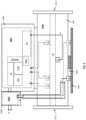
- the measuring system - realized, for example, as a Coriolis mass flow measuring device or as a Coriolis mass flow/density measuring device that additionally measures the density and/or as a Coriolis mass flow/viscosity measuring device that additionally measures the viscosity - comprises an inlet end #111 and an outlet end #112 connected to the process line physical-electrical measuring sensor MW, which is set up to be flowed through by the medium during operation, as well as an electrically coupled to it - in particular formed by at least one microprocessor and / or by means of internal during operation Energy storage and/or supplied with electrical energy externally via connection cable - electronic measuring system electronics ME.
- the electrical coupling or connection of the measuring sensor MW to the measuring system electronics ME can be done using appropriate electrical connection lines and appropriate cable bushings.
- the connecting lines can at least partially be designed as electrical wires, at least in sections, as line wires covered by electrical insulation, for example in the form of “twisted pair” lines, ribbon cables and/or coaxial cables.
- the connecting lines can also be formed, at least in sections, by means of conductor tracks of a, in particular flexible, possibly painted circuit board.
- the measuring system electronics ME which can also be programmed and/or remotely parameterized, can also be designed in such a way that, when the measuring system is in operation, it is connected to a higher-level electronic data processing system (not shown here), for example a programmable logic controller (PLC).
- PLC programmable logic controller
- personal computer and / or a workstation via a data transmission system, for example a fieldbus system and / or wirelessly by radio, can exchange measurement and / or other operating data, for example status messages, such as current measured values or settings and / or used to control the measuring system Diagnostic values.
- the measuring system electronics ME can, for example, have such transmitting and receiving electronics COM, which is fed during operation by a (central) evaluation and supply unit provided in the aforementioned data processing system and remote from the measuring system.
- the measuring system electronics ME (or its aforementioned transmitting and receiving electronics COM) can be designed in such a way that it has a, if necessary Two-wire connection 2L configured as a 4-20 mA current loop can be electrically connected to the aforementioned external electronic data processing system and can use it to obtain both the electrical power required for the operation of the measuring system from the aforementioned evaluation and supply unit of the data processing system and also to transmit measured values to the data processing system , for example by (load) modulation of a direct supply current supplied by the evaluation and supply unit.
- the measuring system electronics ME can also be designed so that it can nominally be operated with a maximum power of 1 W or less and/or is intrinsically safe.
- the measuring system electronics 20 of the measuring system according to the invention can also, for example, have a modular structure, such that various electronic components of the measuring system electronics ME, such as drive electronics Exc for controlling the measuring sensor, measuring and control electronics DSV for processing data from the measuring sensor provided measurement signals and for determining measured values based on measurement signals from the sensor, an internal power supply circuit VS for providing one or more internal operating voltages and / or the aforementioned transmitting and receiving electronics COM, which are used for communication with a higher-level measurement data processing system or an external fieldbus arranged on a separate circuit board and/or each formed by means of its own microprocessor.
- drive electronics Exc for controlling the measuring sensor
- measuring and control electronics DSV for processing data from the measuring sensor provided measurement signals and for determining measured values based on measurement signals from the sensor
- an internal power supply circuit VS for providing one or more internal operating voltages and / or
- the measuring system electronics ME is designed to be modular, such that the measuring system electronics ME has a first electronics module ME1 and a second electronics module ME2 that is electrically coupled to it, for example electrically connected to it by means of electrical connecting lines having; this, for example, in such a way that a signal output of the electronics module ME1 is electrically connected to a signal input of the electronics module ME2.
- the aforementioned signal output of the electronic module ME1 can, for example, be designed to output digital measured values determined based on measurement signals from the sensor, in particular the aforementioned mass flow, density or viscosity measured values.
- the measuring system can also be connected, at least temporarily, to the measuring system electronics 20, for example its aforementioned measuring and control electronics DSV , have a communicating display and control element HMI, such as an LCD, OLED or TFT display placed in the aforementioned electronics housing 200 behind a window provided therein, as well as a corresponding input keyboard and / or a touchscreen.
- HMI communicating display and control element
- the measuring system has an electronics housing 200, for example also of modular design, and the measuring system electronics ME is at least partially, possibly also completely housed within the same electronics housing 200.
- the electronics housing 200 is designed to be modular, such that Electronics housing 200 has a first housing module 200A and a second housing module 200B, for example mechanically connected directly to the same housing module 200A.
- the housing module 200A can also be set up to accommodate the electronics module ME1, and the housing module 200B can be set up accordingly for this purpose be to accommodate the electronic module ME2.
- the electronics housing 200 or a respective housing module thereof can be made, for example, from a metal, such as stainless steel or aluminum, and/or by means of a casting process, such as an investment casting or a die casting process (HPDC); However, it can also be formed, for example, by means of a plastic molding produced in an injection molding process.
- a metal such as stainless steel or aluminum
- HPDC die casting process
- the electronics housing 200 or the aforementioned housing modules can also be designed to be impact-resistant or pressure-resistant and/or to protect against the ingress of dust in damaging quantities and/or splashing water on all sides, for example in such a way that it meets the requirements of the protection class IP 54 in accordance with DIN EN 60529 (VDE 0470-1):2014-09 and/or the requirements of the type of protection "Flameproof enclosure (Ex-d)" in accordance with EN 60079-1:2007.
- the measuring sensor MW is a measuring sensor of the vibration type, namely a measuring sensor with at least one vibration element 10, with at least one electro-mechanical vibration exciter 41 for stimulating and maintaining mechanical vibrations of the at least one vibration element 10 and with a an electrodynamic first vibration sensor 51 and at least one, for example identical to the vibration sensor 51, electrodynamic second vibration sensor 52 for detecting mechanical vibrations of the at least one vibration element 10, both the vibration exciter 41 and the vibration sensors 51, 52 each being electrically coupled to the measuring system electronics 20 are and wherein the at least one vibration element 10 is set up to be contacted by flowing measuring material, for example with the measuring material flowing through and/or around it, and to be allowed to vibrate during this time, for example with at least one resonance frequency inherent in the vibration element or the measuring sensor formed with it .
- the measuring sensor can also be a conventional one - for example from those mentioned at the beginning EP-A 816 807 , US-A 2002/0033043 , US-A 2006/0096390 , US-A 2007/0062309 , US-A 2007/0119264 , US-A 2008/0011101 , US-A 2008/0047362 , US-A 2008/0190195 , US-A 2008/0250871 , US-A 2010/0005887 , US-A 2010/0011882 , US-A 2010/0257943 , US-A 2011/0161017 , US-A 2011/0178738 , US-A 2011/0219872 , US-A 2011/0265580 , US-A 2011/0271756 , US-A 2012/0123705 , US-A 2013/0042700 , US-A 2016/0313162 , US-A 2017/0261474 , US-A 44 91 009 , US-
- the at least one vibration element 10 is - as in Fig. 2 indicated or from a synopsis of the Fig. 1 and 2 readily apparent - housed together with the at least one vibration exciter 41 and the at least two vibration sensors 51, 52 and possibly other components of the measuring sensor MW within a sensor housing 100 of the measuring system; this in particular in such a way that the at least one vibration element 10 is held on the transducer housing 100, for example rigidly connected to the transducer housing 100.
- the same sensor housing 100 has a wall made of a metal, for example stainless steel.
- the sensor housing 100 has a connecting piece for the electronics housing and the electronics housing 200 is mechanically connected to the connecting piece, possibly also releasably.
- the housing module 200A can be attached to the outside of the sensor housing 100, for example in such a way that the housing module 200A is on the outside of the sensor housing 100 and that the housing -Module 200B is attached to the outside of the housing module 200A.
- the vibration element 10 can also - as is usual with measuring sensors of the type in question or vibronic measuring systems formed with them - for example by means of one or more, in particular at least partially straight and / or at least partially circular arc-shaped, tubes with one of one, in particular metallic, Tube wall and a lumen covered by it, the tube or each of the tubes also being designed to guide the at least temporarily flowing fluid measuring material (or of the same measuring material to be flowed through) and to be allowed to vibrate accordingly.
- the vibration element can, for example, also be formed by means of one or more displacer elements placed within a lumen of a tube of the measuring sensor through which the measured substance flows, the displacer element or each of the displacer elements being set up to be flowed around by the measured substance and to be allowed to vibrate accordingly.
- the at least one vibration exciter 41 is in turn designed to convert electrical power fed there into forced mechanical vibrations of the at least one vibration element 11 causing mechanical power.
- the at least one vibration exciter 41 for example designed as an electrodynamic, electromagnetic or piezoelectric - as in Fig. 2 indicated and quite common in vibration-type measuring sensors or vibronic measuring systems formed with them - positioned so that a force generated thereby acts on the vibration element in the direction of an imaginary line of force running through a center of mass of the at least one vibration element, and / or that the vibration exciter 41 - like also in Fig. 2 shown - is the only vibration exciter that causes vibrations of the vibration element 10.
- the measuring system electronics ME of the measuring system according to the invention is also intended and set up accordingly to generate an - for example bipolar and / or at least temporarily periodic, possibly also harmonic - electrical driver signal e1 and thus to feed electrical power into the at least one vibration exciter 41, in such a way that the at least one vibration element 10 at least partially carries out useful vibrations, namely forced mechanical vibrations with a useful frequency f N , which are suitable for generating Coriolis forces in the flowing medium that are dependent on the mass flow but nevertheless act back on the vibration element 10, in such a way that the aforementioned useful vibrations Coriolis oscillations, namely mechanical oscillations with the useful frequency f N which are additionally forced by the Coriolis forces and are dependent on the mass flow m of the medium to be measured.
- useful vibrations namely forced mechanical vibrations with a useful frequency f N
- the driver signal e1 can accordingly, for example, be a harmonic electrical signal which forms the aforementioned signal component e1 N which determines the useful frequency f N or, for example, a multi-frequency electrical signal which is composed of several (spectral) signal components, but nevertheless contains a spectral useful component e1 N which determines the useful frequency f N be a signal.
- the useful vibrations excited by means of the vibration exciter 41 and the measuring system electronics ME connected to it can also, for example, be bending vibrations of the at least one Vibration element 10 is an associated rest position, the useful frequency f and/or a lowest instantaneous resonance frequency of the at least one vibration element 10 can be selected, namely set by means of the driver signal e1.
- the measuring system electronics ME can, for example, have a corresponding drive electronics Exc exhibit.
- the drive electronics Exc has a digital frequency output.
- the drive electronics Exc is also set up to output a frequency sequence at the same frequency output, namely a sequence of digital frequency values that quantify the signal frequency set for the driver signal e1, for example namely the currently set useful frequency (or the signal frequency of its signal component eN1).
- the measuring sensor MW is also equipped with electrodynamic vibration sensors 51, 52 in order to detect mechanical vibrations of the at least one vibration element 11, not least also forced mechanical vibrations of the at least one vibration element 11, the vibration sensor 51, for example, by means of a first Moving coil and the vibration sensor 52 can be formed, for example, by means of a second moving coil.
- the vibration sensor 51 is set up to convert vibration movements of the at least one vibration element 11 at a first measuring point into an electrical first vibration measurement signal s1 of the measuring sensor, such that - as in Fig.
- the same vibration measurement signal s1 has at least one (dependent on the time t) first useful component s1 N , namely an alternating voltage component with a frequency corresponding to the useful frequency f N
- the vibration sensor 52 is set up to detect vibration movements of the at least one vibration element at one of the first measuring points to convert the remote second measuring point into an electrical second vibration measurement signal s2 of the sensor, such that - as in Fig. 3 indicated - the same vibration measurement signal s2 has at least one second useful component s2 N (dependent on the time t), namely an alternating voltage component with a frequency corresponding to the useful frequency f N.
- each of the two vibration sensors 51, 52 is an electrodynamic vibration sensor
- the useful component s1 N accordingly has an amplitude U1 N which is dependent on the useful frequency f N and on a first magnetic flux ⁇ 1, namely a magnetic flux through the vibration sensor 51 (or dependent voltage level) and the useful component s2 N depends on the useful frequency f N and a second magnetic flux ⁇ 2, namely one magnetic flux through the vibration sensor 52 dependent amplitude U2 N (or dependent voltage level).
- Each of the two vibration sensors can, as is quite common with measuring sensors of the type in question, be formed, for example, by means of a moving coil.
- the first vibration sensor has a first permanent magnet, for example mechanically connected to the at least one vibration element to form the first measuring point, and a first permanent magnet, for example mechanically connected to the at least one vibration element 11 and / or to the sensor -Housing 100 has a first air coil connected and that the second vibration sensor has a second permanent magnet, for example mechanically connected to the at least one vibration element 11 to form the second measuring point, and a second permanent magnet, for example mechanically connected to the at least one vibration element and / or to the sensor - Housing 100 connected, second air coil.
- the vibration measurement signals s1, s2 generated by the measuring sensor 10 are subsequently fed to the measuring system electronics ME, for example via electrical connecting lines, in order to be processed accordingly, for example by means of digital signal processing (DSV), for example pre-amplified, filtered and digitized and then evaluated accordingly to become.
- DSV digital signal processing
- the vibration sensors 51, 52 are also arranged so that in the event of an excitation of the aforementioned Coriolis vibrations of the at least one vibration element 11, each of the useful components s1 N , s2 N of the vibration measurement signals s1 and s2 also each receive one of the mass flow m the phase angle that is dependent on the phase angle flowing through the measuring sensor 10 and can be measured, for example, relative to the driver signal e1 or its useful component e1 N ; this in particular in the way that, as in Fig.
- ⁇ 12 f(m)
- the vibration sensors 51, 52 can, like such measurement sensors, be quite common or even in Fig.
- the vibration sensor 51 is on the inlet side at least one Vibration element 11 or in its vicinity and the vibration sensor 52 are arranged on the outlet side of at least one vibration element 11 or in its vicinity.
- the two vibration sensors 51, 52 can also be the only vibration sensors useful for detecting vibrations of the at least one vibration element 11, such that the measuring sensor does not have any other vibration sensors apart from the same vibration sensors 51, 52.
- the measuring sensor has at least one temperature sensor 71 for detecting a temperature of the measuring sensor at a temperature measuring point, which is set up to generate a temperature measuring signal, namely a measuring signal representing the temperature at the temperature measuring point, in particular. with a temperature-dependent electrical voltage and/or a temperature-dependent electrical current.
- the measuring sensor can, for example, also have at least one strain sensor which is used to detect mechanical stresses within the measuring sensor.
- the measuring system electronics ME is, in addition to generating the driver signal e1, also intended or set up to receive and evaluate the vibration measurement signals s1, s2, namely based on the vibration measurement signals s1, s2, for example based on the aforementioned phase difference ⁇ 12 between the first and second useful components to determine mass flow measurement values representing the mass flow, for example also to output them in the form of analog values and / or in the form of digital values.
- the measuring system electronics 20 is also set up to first determine the phase difference ⁇ 12 based on the vibration measurement signals s1, s2.
- the measuring system electronics ME can also be set up to determine the respective predetermined phase angle of its respective useful component s1 N, s2 N from at least one of the applied vibration measurement signals s1 , s2, for example relative to the driver signal e1 or its pre-determined useful component e1 N , and /or to determine the useful frequency f N based on at least one of the vibration measurement signals s1, s2, for example also during operation at least one phase sequence, namely a sequence of digital phase values corresponding to quantifying the phase angle of one of the first and second useful components and/or a frequency sequence, namely a sequence to generate digital frequency values quantifying the useful frequency f N , such that the phase sequence corresponds to a time profile of the phase angle of the corresponding useful component or the frequency sequence corresponds to a time profile of the useful frequency.
- phase angles or the generation of the aforementioned phase sequence can, for example, as is quite common with Coriolis mass flow measuring devices, by means of a quadrature demodulation (Q/I demodulation) of the respective vibration measurement signal, which is carried out accordingly in the measuring system electronics ME, with a signal having the useful frequency first harmonic reference signal (Q) and a second harmonic reference signal (I) which is 90 ° out of phase with it.
- Q/I demodulation quadrature demodulation of the respective vibration measurement signal
- the useful vibrations caused by means of driver signal e1 are resonance vibrations of the at least one vibration element 11
- the useful frequency f N of the vibration measurement signals s1, s2 can serve as a measure for the density and/or the viscosity of the medium to be measured and can accordingly be determined by means of the Measuring system electronics ME the density and / or the viscosity are determined based on the aforementioned frequency sequence.
- the measuring system electronics 20 is also set up according to a further embodiment of the invention to receive the temperature measurement signal generated by the temperature sensor or the strain measurement signal generated by the strain sensor to receive and process, in particular to digitize and evaluate; this, for example, in such a way that the measuring system electronics ME determines a temperature of the displacement element and/or a temperature of the medium to be measured based on the at least one temperature measurement signal.
- the measuring system electronics ME can also have corresponding measuring and control electronics DSV, which, as in Fig. 2 shown schematically, is electrically connected to the measuring sensor 10 or its vibration sensors 51, 52, for example in such a way that from the measuring and control electronics DSV a first measuring signal input of the measuring system electronics ME for the vibration measuring signal s1 and at least a second measuring signal input of the measuring system electronics 20 are formed for the vibration measurement signal s2.
- the measuring and control electronics DSV can advantageously be set up to digitally process the supplied vibration measurement signals s1, s2, and possibly also the temperature and/or strain measurement signals, for example by means of at least one microprocessor and/or at least one digital signal processor (DSP) and/or be formed by means of a programmable logic component (FPGA) and/or by means of a customer-specific programmed logic component (ASIC).
- DSP digital signal processor
- FPGA programmable logic component
- ASIC customer-specific programmed logic component
- the program codes executed during operation of the measuring system in one or more of the aforementioned microprocessors or digital signal processors of the measuring system electronics ME can each be stored persistently, for example, in one or more non-volatile data memories (EEPROM) of the measuring system electronics ME and when starting the same be loaded into a volatile data memory (RAM) provided in the measuring system electronics ME or the measuring and control electronics DSV, for example integrated in the microprocessor.
- EEPROM non-volatile data memories
- RAM volatile data memory
- the vibration measurement signals s1, s2 must of course first be converted into corresponding digital signals for processing in the microprocessor or in the digital signal processor using appropriate analog-to-digital converters (A/D), for example by digitizing the respective signal voltage of the vibration measurement signals s1, s2 , see for example those mentioned at the beginning US-B 63 11 136 or US-A 2011/0271756 .
- A/D analog-to-digital converters
- Volatile electronic data memory EEPROM is provided, which is set up to hold digital data, for example even without an applied operating voltage.
- the aforementioned phase sequence and/or the aforementioned frequency sequence can also be generated, for example also output at a corresponding digital phase output or at a corresponding digital frequency output and thus for further processing in the measuring system electronics ME to be provided.
- the measuring system electronics ME is formed by means of the aforementioned drive electronics Exc and by means of the aforementioned measuring and control electronics DSV, its phase output can be connected to a phase input provided in the drive electronics Exc, for example also a component of the aforementioned
- phase comparator forming a phase locked loop can be electrically connected and the same phase comparator can also be set up to determine a phase difference between the aforementioned signal component e1 N of the driver signal e1 and at least one of the useful components s1 N , s2 N based on the phase sequence and/or an extent thereof Determine phase difference.
- the measuring and control electronics DSV is also set up to generate the aforementioned first and second useful component sequences and to output at least one of the useful component sequences to a digital amplitude output.
- the aforementioned amplitude output of the measuring and control electronics DSV can also be electrically connected, for example, to an amplitude input of the drive electronics Exc which detects an amplitude of the oscillations of the at least one vibration element 11, and the drive electronics Exc can also be set up to generate the driver signal e1 based on the amplitude sequence to generate that the vibrations of the at least one vibration element or its useful vibrations reach a predetermined vibration amplitude or do not permanently exceed or fall below it.
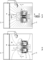
- the useful components of the two vibration measurement signals s1, s2 or their amplitudes due to the operating principle of the two electrodynamic vibration sensors, depend on the temporal change in the respective magnetic flux within the vibration sensor, in the case of a moving coil as a vibration sensor, namely the linking or .Induction flux within the respective air coil, depending;
- the causes of such an external magnetic field H1 can be, for example, an electric field generated in the vicinity of the respective measuring system, for example due to electric motors, transformers, inverters or high electrical (System components carrying direct currents, such as busbars, and/or can - as in Fig. 4b indicated - a magnet positioned outside the respective measuring system or in its vicinity, for example an electromagnet or a permanent magnet.
- Such an undesirable influence on the first and/or second useful component s1 N , s2 N or impairment of the functionality of the measurement sensor by an external magnetic field H1 can also consist, for example, in the fact that - as in Fig. 3 indicated - at least one of the useful components contains an additional interference component of the same frequency (S1 N,Err , S2 N,Err ), such that the aforementioned phase angle of the same useful component, and therefore also the aforementioned phase difference ⁇ 12 ( ⁇ 12 -> ⁇ 12 Err ), then produces a phase error, namely has a portion dependent on the external magnetic field H1 or its influence on the magnetic flux ultimately established in the respective vibration sensor; this, for example, in such a way that the integrity of at least one of the vibration measurement signals or the mass flow measurement values is unacceptably reduced or that the same phase error leads to a measurement accuracy with which the measuring system electronics 20 then determines the mass flow measurement values from a tolerance range specified for the measuring system .
- the magnetic field detector 61 is positioned in particular outside the sensor housing 100; This is particularly the case in such a way that the magnetic field detector 61 is also positioned outside the aforementioned electronics housing 200.
- the magnetic field detector 61 can, for example, be attached to the outside of the sensor housing 100, in particular also be fixed directly on the sensor housing. According to a further embodiment of the invention, it is further provided that the magnetic field detector 61 is positioned in the vicinity of the vibration sensor 51, for example less than 5 cm away from it.
- the magnetic field detector 61 is in particular set up to convert changes in the magnetic field H0 + H1 at a third measuring point formed by the magnetic field detector 61 and distant from both the aforementioned first measuring point and the aforementioned second measuring point into a, for example, electrical, first magnetic field signal ⁇ 1, which is a has an amplitude U3 which is dependent on a third magnetic flux ⁇ 3 - established here both outside the vibration sensor 51 and outside the vibration sensor 52, namely a magnetic flux through the magnetic field detector 61 and/or on a surface density B3 of the same magnetic flux ⁇ 3; this in particular in such a way that the magnetic field signal ⁇ 1 follows at least one change in the magnetic flux ⁇ 3 and/or its surface density B3 with a change in the amplitude U3.
- the magnetic field detector 61 can be formed, for example, by means of at least one Hall sensor and/or by means of at least one reed switch.
- the magnetic field detector is also electrically connected to the measuring system electronics 20 via connecting lines that run along the outside of the sensor housing.
- the same connecting lines can also be provided, for example, by means of a connecting cable and / or laid at least in sections within a protective tube or protective tube attached to the outside of the sensor and / or electronics housing.
- the measuring system electronics 20 is also set up to use the magnetic field signal ⁇ 1 to at least qualitatively determine whether the aforementioned external magnetic field H1 is also established within the measuring sensor - in addition to the aforementioned internal magnetic field H0 - for example to determine, whether there is a fault in the sensor due to the same external magnetic field H1, in particular reducing the functionality of the measuring sensor and/or causing a malfunction of the measuring sensor as a whole and/or reducing the integrity of at least one of the first and second vibration measurement signals or the mass flow measured values.
- the magnetic field signal ⁇ 1 can, for example, be a signal that only evaluates the aforementioned magnetic field H0 + H1 or its changes qualitatively or only assumes discrete values to a limited extent, for example a signal that nominally only has two Binary switching signal having states.
- the magnetic field signal ⁇ 1 can, for example, also be an analog signal that continuously quantifies the magnetic field H0 + H1 or its changes in value and time, for example an analog electrical signal with an electrical voltage that is dependent on the magnetic flux ⁇ 3 and/or its surface density B3.
- the measuring system electronics 20 is also set up, according to a further embodiment of the invention, to at least occasionally use the at least one magnetic field signal to determine one or more key figure values for at least one - for example, to calculate an influence on the measuring sensor by the external magnetic field and/or an influence on at least one of the magnetic fluxes ⁇ 1, ⁇ 2 - magnetic field index MK1, such that the same magnetic field index MK1; this in particular in such a way that the same magnetic field characteristic MK1 is dependent on a deviation of the magnetic flux ⁇ 1 from the magnetic flux ⁇ 2 and/or the same deviation is evaluated and/or quantified; alternatively the same
- the magnetic field characteristic MK1 can be determined repeatedly during operation of the Coriolis mass flow measuring device using the measuring system electronics ME, for example using digital amplitude values determined for the amplitude U3 of the magnetic field signal ⁇ 1.
- the measuring system electronics ME can also be set up to store one or more of the aforementioned digital amplitude values for the amplitude U3 in the same data memory EEPROM to store, for example together with a numerical value for a time variable (time stamp) corresponding to a respective point in time when the respective key figure value was determined.
- the measuring system electronics 20 is further set up according to a further embodiment of the invention to evaluate one or more key figure values for the at least one magnetic field key figure MK1, for example namely each with one or more previously determined for the same magnetic field characteristic MK1, for example not in the aforementioned to compare reference values BK1 1 (BK1 1 , BK1 2 ,... BK1 i ...) stored in the volatile electronic data memory EEPROM.
- the measuring system electronics ME is also set up to determine whether one or more key figure values for the magnetic field key figure MK1 are greater than one or more such reference values for the magnetic field key figure MK1, for example namely representing a measuring system that is no longer intact and if necessary, for example, also to issue a (fault) message signaling this, for example to display it on site and / or to transmit it as a status message to the aforementioned electronic data processing system.
- the aforementioned reference values for the magnetic field characteristic MK1 can be, for example, a reduced functionality of the measuring sensor (attributable to an external magnetic field) or a reference value representing a malfunction of the measuring sensor (attributable to an external magnetic field).
- reference values can, for example, be determined in advance, for example by the manufacturer of the measuring system or during a (factory) calibration carried out during the production of the measuring system and/or during commissioning on site, and/or during operation of the measuring system; this, for example, in such a way that the respective magnetic field index MK1 is first determined for the completed, therefore intact measuring system and is converted into the reference value BK1 1 using a tolerance value corresponding to a still tolerable influence and/or by the magnetic field index MK1 using the in The measurement system is determined directly in the vicinity of a magnet that creates a reference magnetic field but is otherwise intact and is stored as a reference value BK1 1 in the data memory EEPROM.
- the determination of the key figure values MK1 or the determination of the presence of an external magnetic field can, for example, be initiated or suspended again automatically, for example in a time-controlled manner and/or depending on changes in other diagnostic values.
- the determination of the key figure values can also be initiated and/or suspended externally to the measuring system, for example starting from the aforementioned electronic data processing system via the aforementioned transmitting and receiving electronics COM and/or starting from operating personnel on site via the aforementioned display. and HMI control element.
- the measuring system electronics 20 is set up to receive and evaluate a start command which initiates at least the determination of the key figure values for at least the magnetic field key figure MK1, possibly also its aforementioned evaluation, namely an input of the start command to detect and then initiate a determination of the key figure values for the first magnetic field key figure MK1 and / or the measuring system electronics is set up to receive and evaluate a stop command that at least temporarily prevents the determination of the key figure values for the magnetic field key figure MK1 , namely to detect an input of the stop command and then at least temporarily stop a determination of the key figure values for the first magnetic field key figure MK1.
- the electronics module ME1 can, for example, be set up to both generate the aforementioned driver signal e1 and to receive and evaluate the vibration measurement signals s1, s2
- the electronic module ME2 can, for example, be set up to receive and evaluate the magnetic field signal ⁇ 1, for example to calculate the aforementioned magnetic field characteristic number MK1 and/or to compare it with the aforementioned reference values BK1 1 and/or to calculate the aforementioned (disturbance) )generate message.
- a signal output of the electronics module ME2 can be electrically connected to a corresponding signal input of the electronics module ME1 and the electronics module ME2 can be set up to transmit the aforementioned (fault) message to the electronics module ME1.
- the electronics module ME2 can be set up to receive measured values determined by the electronics module ME1 and output them accordingly at a signal output, for example in such a way that no measured values, in particular no mass flow measured values, are output in the event of a malfunction is present due to the external magnetic field H1, or that mass flow measurement values are only output as qualified measurement values of the measuring system if there is no such disturbance.
- the measuring system electronics 20 is also set up to monitor the functionality of the magnetic field detector 61 itself, for example by evaluating the magnetic field signal ⁇ 1; this in particular in such a way that the measuring system electronics ME checks based on the magnetic field signal ⁇ 1 and / or based on a measurement of an electrical resistance and / or an electrical impedance of the connecting lines electrically connecting the magnetic field detector 61 and the measuring system electronics ME whether magnetic field detector 61 and Measuring system electronics ME are still electrically connected to each other.
- the measuring system comprises a protective shield made, for example, of stainless steel, approximately 1.4404 (St 316L). 300 for the at least one magnetic field detector.
- protective shield 300 is, as in Fig. 2 shown schematically, positioned outside the pickup housing 100 to form a gap 300* located between the protective shield and the pickup housing 100 and suitable for accommodating at least the magnetic field detector 61, and the magnetic field detector 61 is then positioned within the gap.
- the protective shield 300 can, for example, be attached to the outside of the sensor housing 100, for example connected to it in a materially bonded manner, in particular welded to it.
- the protective shield 300 can also be releasably connected to the sensor housing 100, for example screwed to it and/or strapped onto the sensor housing 100. Alternatively or in addition can the protective shield 300 can also be attached to the aforementioned electronics housing 200.
- the protective shield 300 can also be set up or designed, for example, to shield the measuring sensor or both the measuring sensor MW and the magnetic field detector against the external magnetic field H1.
- the protective shield 300 can also consist at least partially of a ferromagnetic material, for example a ferritic steel.
- the protective shield is releasably connected to the transducer housing 100 and/or the electronics housing 200
- the protective shield 300 is attached to the transducer housing or on the transducer housing by means of at least one seal Electronics housing secured, for example against unauthorized removal.
- a further embodiment of the invention provides that the measuring system for detecting the magnetic field - as in Fig. 2 . or 5a and 5b each indicated or also readily apparent from their synopsis - at least one second magnetic field detector 62, for example also of the same construction as the magnetic field detector 61, which is set up to detect changes in the magnetic field H0 or H0+H1 on one of the aforementioned third
- the fourth measuring point away from the measuring point for example also from the first measuring point and / or from the second measuring point, into a second magnetic field signal ⁇ 2, in particular, which evaluates the same changes in the magnetic field and / or quantifies the changes and / or electrical, the one of a fourth magnetic flux ⁇ 4, namely a magnetic flux through the magnetic field detector 62 and / or an amplitude U4 dependent on a surface density B4 of the same magnetic flux ⁇ 4, such that the magnetic field signal ⁇ 2 is based on at least a
- the measuring system electronics 20 is also set up to receive and evaluate the magnetic field signal ⁇ 2, namely to use the magnetic field signal ⁇ 2 to determine whether the external magnetic field H1 is present.
- the magnetic field signal ⁇ 2 can also be designed as an analog signal, for example with an electrical voltage that depends on the magnetic flux ⁇ 4 and/or its surface density B4.
- the magnetic field detector 62 can be formed by means of a Hall sensor and/or a reed switch. According to a further embodiment of the invention, it is also provided that the magnetic field detector 62 is positioned outside the sensor housing 100, for example, is attached to the outside of the sensor housing 100.
- the magnetic field detector 62 can be positioned, for example, in the vicinity of the vibration sensor 52, in particular less than 5 cm and/or less far away from the vibration sensor 52 than from the vibration sensor 51. Alternatively or in addition, the magnetic field detector 62 can, for example, also be positioned less far away from the vibration sensor 51 than from the vibration sensor 52. For the aforementioned case that the measuring system has a protective shield, the magnetic field detector 62 can, for example, also be positioned next to the magnetic field detector 61 in the gap.
- the measuring system can also have further magnetic field detectors, for example in such a way that magnetic field detectors are located both on the front and back of the transducer housing and/or on both the left and right sides of the transducer housing/or on both the top and bottom of the transducer -Housing are positioned or in such a way that at least one magnetic field detector, for example two or more and / or the same number of magnetic field detectors, are arranged on at least two opposite sides of the measuring sensor or its sensor housing.
Description
Die Erfindung betrifft ein vibronisches Meßsystem, insb. ein Coriolis-Massedurchfluß-Meßgerät, zum Messen eines Massestroms eines fluiden Meßstoff.The invention relates to a vibronic measuring system, in particular a Coriolis mass flow measuring device, for measuring a mass flow of a fluid medium.
In der industriellen Meßtechnik werden - insb. auch im Zusammenhang mit der Regelung und Überwachung von automatisierten verfahrenstechnischen Prozessen - zur hochgenauen Ermittlung einer oder mehrerer Meßgrößen, beispielsweise eines Massestroms und/oder einer Dichte, eines in einer Prozeßleitung, beispielsweise einer Rohrleitung, strömenden Meßstoffs, beispielsweise einer Flüssigkeiten, eines Gases oder einer Dispersion, oftmals jeweils mittels einer - zumeist mittels wenigstens eines Mikroprozessors gebildeten Meßelektronik - sowie einem mit nämlicher Meßsystem-Elektronik elektrisch verbundenen, im Betrieb vom zu messenden Meßstoff durchströmten Meßaufnehmer vom Vibrationstyp gebildeten vibronischen Meßsyteme verwendet. Beispiele für solche, beispielsweise auch als Coriolis-Massedurchfluß-Meßgeräte, Coriolis-Massedurchfluß-Dichte-Meßgeräte und/oder Coriolis-Massedurchfluß-Viskositäts-Meßgeräte, ausgebildeten Meßsysteme sind u.a. in der
Der Meßaufnehmer eines jeden der darin gezeigten Meßsysteme umfaßt wenigstens ein Vibrationselement, das typischerweise als ein zumindest abschnittsweise gerades und/oder zumindest abschnittsweise gekrümmtes, z.B. U-, V-, S-, Z- oder Ω-artig geformtes, Meßrohr mit einem von einer Rohrwand umgebenen Lumen zum Führen des Meßstoffs ausgebildet ist, oder das - wie u.a. auch in der
Es ist zudem bekannt, das wenigstens eine Vibrationselement, beispielsweise zwecks Durchführung wiederkehrender Überprüfungen des Meßaufnehmers während des Betriebs des Meßgeräts, gelegentlich auch zu zeitlich andauernden erzwungenen Schwingungen außer Resonanz anzuregen oder gelegentlich auch freie gedämpfte Schwingungen des wenigstens einen Vibrationselements zu ermöglichen sowie nämliche Schwingungen jeweils auszuwerten, etwa um, wie u.a. auch in der vorgenannten
Bei Meßaufnehmern mit zwei jeweils als Meßrohr ausgebildeten Vibrationselementen sind diese zumeist über ein sich zwischen den Meßrohren und einem einlaßseitigen Anschlußflansch erstreckenden einlaßseitig Verteilerstück sowie über ein sich zwischen den Meßrohren und einem auslaßseitigen Anschlußflansch erstreckenden auslaßseitig Verteilerstück in die jeweilige Prozeßleitung eingebunden. Bei Meßaufnehmern mit einem einzigen Meßrohr als Vibrationselement kommuniziert letzteres zumeist über ein einlaßseitig einmündendes Verbindungsrohr sowie über ein auslaßseitig einmündendes Verbindungsrohr mit der Prozeßleitung. Ferner umfassen Meßaufnehmer mit einem einzigen Meßrohr als Vibrationselement jeweils wenigstens ein weiteres, nämlich als ein, beispielsweise rohr-, kasten- oder plattenförmigen, Gegenschwinger ausgebildetes, gleichwohl nicht vom Meßstoff kontaktiertes Vibrationselement, das unter Bildung einer ersten Kopplungszone einlaßseitig an das Meßrohr gekoppelt ist und der unter Bildung einer zweiten Kopplungszone auslaßseitig an das Meßrohr gekoppelt ist, und das im Betrieb im wesentlichen ruht oder entgegengesetzt zum Meßrohr oszilliert. Das dabei mittels Meßrohr und Gegenschwinger gebildete Innenteil des Meßaufnehmers ist zumeist allein mittels der zwei Verbindungsrohre, über die das Meßrohr im Betrieb mit der Prozeßleitung kommuniziert, in einem schutzgebenden Aufnehmer-Gehäuse gehaltert, insb. in einer Schwingungen des Innenteils relativ zum Aufnehmer-Gehäuse ermöglichenden Weise. Bei den beispielsweise in der
Zum aktiven Anregen bzw. Aufrechterhalten von Schwingungen des wenigstens einen Vibrationselements, nicht zuletzt auch den vorbezeichneten Nutzschwingungen, weisen Meßaufnehmer vom Vibrationstyp des weiteren wenigstens einen im Betrieb auf das wenigstens eine Vibrationselement einwirkenden elektromechanischen, typischerweise ebenfalls elektrodynamischen Schwingungserreger auf. Der mittels eines Paars elektrischer Anschlußleitungen, beispielsweise in Form von Anschlußdrähten und/oder inform von Leiterbahnen einer flexiblen Leiterplatte, mit der vorbezeichneten Meßsystem-Elektronik elektrisch verbundene Schwingungserreger dient im besonderen dazu, angesteuert von einem in der Meßsystem-Elektronik vorgesehenen Antriebselektronik generierten und entsprechend konditionierten, nämlich zumindest an sich verändernde Schwingungseigenschaften des wenigstens einen Vibrationselements angepaßten elektrischen Treibersignal eine mittels nämlichen Treibersignals eingespeiste elektrische Erregerleistung in eine an einem vom Schwingungserreger gebildeten Angriffspunkt auf das wenigstens eine Vibrationselement wirkende Antriebskraft zu wandeln. Die Antriebselektronik ist im besonderen auch dafür eingerichtet, das Treibersignal mittels interner Regelung so einzustellen, daß es eine der anzuregenden, gelegentlich auch zeitlich ändernden Nutzfrequenz entsprechende Signalfrequenz aufweist, ggf. als bei einer durch einen Erregerstrom, nämlich einen elektrischen Strom des Treibersignals vorgegebenen Schwingungsamplitude. Das Treibersignal kann beispielsweise im Betrieb des Meßgeräts gelegentlich auch abgeschaltet werden, beispielsweise zwecks Ermöglichen der vorbezeichneten freien gedämpften Schwingungen des wenigstens einen Vibrationselements oder beispielsweise, wie in der eingangs erwähnten
Schwingungserreger marktgängiger Meßaufnehmer vom Vibrationstyp sind typischerweise nach Art einer nach dem elektrodynamischen Prinzip arbeitenden Schwingspule, nämlich einer Luftspule-Magnet-Anordnung aufgebaut, die mittels einer - bei Meßaufnehmern mit einem Meßrohr und einem daran gekoppelten Gegenschwinger gebildeten Vibrationselementen zumeist an letzterem fixierten - Luftspule, nämlich einer keinen magnetischen Kern, sondern vielmehr Luft einschließenden Spule sowie einen mit der wenigstens einen Luftspule wechselwirkenden als Anker dienenden - beispielsweise entsprechend an vorbezeichnetem Meßrohr fixierten - Permanentmagneten gebildet ist und bei der die jeweilige Luftspule zumindest teilweise in einem einen Magnetischer Fluß führenden Luftspalt des Permanentmagneten positioniert ist. Permanentmagneten und Luftspule sind dabei üblicherweise so ausgerichtet, daß sie zueinander im wesentlichen koaxial verlaufen, und zudem dafür eingerichtet, relativ zueinander bzw. gegengleich bewegt zu werden, derart, daß bei durch die Luftspule fließendem Erregerstrom der Permanentmagnet und die in dessen Luftspalt befindliche Luftspule im wesentlichen translatorisch hin- und her bewegt werden. Zudem ist bei herkömmlichen Meßaufnehmern der Schwingungserreger zumeist so ausgebildet und plaziert, daß er im wesentlichen mittig an das wenigstens eine Meßrohr angreift. Alternativ zu einem eher zentral und direkt auf das wenigstens eine Vibrationselement wirkenden Schwingungserreger können, wie u.a. in der eingangs erwähnten
Aufgrund der Nutzschwingungen des wenigstens einen Vibrationselements, werden - nicht zuletzt auch für den Fall, daß die Nutzschwingungen des wenigstens einen Vibrationselements quer zur Strömungsrichtung auf den strömenden Meßstoff wirkende Biegeschwingungen sind - im Meßstoff bekanntlich auch vom momentanen Massestrom abhängige Corioliskräfte induziert. Diese wiederum können vom Massestrom abhängige, sich den Nutzschwingungen überlagernde Coriolisschwingungen des Vibrationselements, ebenfalls mit Nutzfrequenz, bewirken, derart, daß zwischen einlaßseitigen und auslaßseitigen Schwingungsbewegungen des die Nutzschwingungen ausführenden und zugleich vom Medium durchströmten wenigstens einen Meßrohrs eine auch vom Massestrom abhängige, mithin auch als Maß für die Massestrommessung nutzbare Laufzeit- bzw. Phasendifferenz detektiert werden kann. Bei einem zumindest abschnittsweise gekrümmtem Meßrohr als Vibrationselement, bei dem für die Nutzschwingungen eine Schwingungsform, in der nämliches Meßrohr nach Art eines an einem Ende eingespannten Auslegers pendeln gelassen wird, gewählt ist, entsprechen die resultierenden Coriolisschwingungen beispielsweise jenem - gelegentlich auch als Twist-Mode bezeichneten - Biegeschwingungsmode, in dem das Meßrohr Drehschwingungen um eine senkrecht zur erwähnten gedachten Schwingungsachse ausgerichtete gedachte Drehschwingungsachse ausführt, wohingegen bei einem geraden Meßrohr als Vibrationselement, dessen Nutzschwingungen als Biegeschwingungen in einer einzigen gedachten Schwingungsebene ausgebildet sind, die Coriolisschwingungen beispielsweise als zu den Nutzschwingungen im wesentlichen koplanare Biegeschwingungen sind.Due to the useful vibrations of the at least one vibration element, - not least in the case that the useful vibrations of the at least one vibration element are bending vibrations acting transversely to the direction of flow on the flowing medium to be measured - Coriolis forces are also known to be induced in the medium to be measured and are dependent on the instantaneous mass flow. These in turn can cause Coriolis oscillations of the vibration element, which are dependent on the mass flow and are superimposed on the useful vibrations, also with a useful frequency, in such a way that between the inlet-side and outlet-side oscillatory movements of the at least one measuring tube that carries out the useful vibrations and at the same time has the medium flowing through it, there is also a measurement tube that is also dependent on the mass flow, and therefore also as Measurement of the transit time or phase difference that can be used for mass flow measurement can be detected. In the case of a measuring tube that is curved at least in sections as a vibration element, in which a vibration form is selected for the useful vibrations in which the same measuring tube is allowed to oscillate in the manner of a cantilever clamped at one end, the resulting Coriolis vibrations correspond, for example, to that - sometimes also referred to as twist mode - Bending vibration mode in which the measuring tube carries out torsional vibrations about an imaginary torsional vibration axis aligned perpendicular to the mentioned imaginary vibration axis, whereas in the case of a straight measuring tube as a vibration element, the useful vibrations of which are designed as bending vibrations in a single imaginary vibration plane, the Coriolis vibrations, for example, are essentially coplanar with the useful vibrations Bending vibrations are.
Zum Erfassen sowohl einlaßseitiger als auch auslaßseitiger Schwingungsbewegungen des wenigstens einen Vibrationselements, nicht zuletzt auch den den Nutzschwingungen entsprechenden, und zum Erzeugen wenigstens zweier von der zu messenden Massestrom beeinflußten elektrischen Schwingungsmeßsignalen weisen Meßaufnehmer der in Rede stehenden Art desweiteren zwei oder mehr entlang des wenigstens einen Vibrationselements voneinander beabstandete, beispielsweise jeweils mittels eines eigenen Paars elektrischer Anschlußleitungen mit eine in der vorbezeichneten Meßsystem-Elektronik elektrisch verbundenen, Schwingungssensoren auf. Jeder der Schwingungssensoren ist eingerichtet, die vorbezeichneten Schwingungsbewegungen an einem jeweiligen Meßpunkt zu erfassen und jeweils in ein nämliche Schwingungsbewegungen repräsentierendes elektrisches Schwingungsmeßsignal zu wandeln, das eine Nutzkomponente, nämlich eine (spektrale) Signal- bzw. nämlich eine Wechselspannungskomponente mit einer der Nutzfrequenz entsprechenden (Signal-)Frequenz und einer von der Nutzfrequenz und einem im jeweiligen Schwingungssensor etablierten magnetischer Fluß abhängigen (Signal-)Amplitude enthält, und nämliches Schwingungsmeßsignal jeweils der Meßsystem-Elektronik, beispielsweise nämlich einer mittels wenigstens eines Mikroprozessors gebildeten Meß- und Steuer-Elektronik der Meßsystem-Elektronik, zur weiteren, ggf. auch digitalen Verarbeitung zur Verfügung zu stellen. Zudem sind die wenigstens zwei Schwingungssensoren so ausgestaltet und angeordnet, daß die vorbezeichnete Nutzkomponente der damit generierten Schwingungsmeßsignale zudem jeweils einen vom Massestrom abhängigen Phasenwinkel aufweisen, derart zwischen den Nutzkomponenten beider Schwingungsmeßsignale eine vom Massestrom abhängige Laufzeit- bzw. Phasendifferenz meßbar ist. Basierend auf nämlicher Phasendifferenz ermittelt die Meßsystem-Elektronik wiederkehrend den Massestrom repräsentierende Massedurchfluß-Meßwerte. In Ergänzung zur Messung des Massestroms kann - etwa basierend auf der Nutzfrequenz und/oder auf einer für die Anregung bzw. Aufrechterhaltung der Nutzschwingungen erforderlichen elektrischen Erregerleistung bzw. einer anhand dessen ermittelten Dämpfung der Nutzschwingungen - zusätzlich auch die Dichte und/oder die Viskosität des Mediums gemessen und von der Meßsystem-Elektronik zusammen mit dem gemessenen Massestrom in Form qualifizierter Meßwerte ausgegeben werden. Typischerweise sind die beiden Schwingungssensoren als elektrodynamische Schwingungssensoren ausgebildet, insb. nämlich gleichermaßen wie der wenigstens eine Schwingungserreger jeweils mittels einer - hier als Tauchspule dienlichen - Luftspule-Magnet-Anordnung gebildet, bei der ebenfalls jeweils eine Luftspule zumindest teilweise in einem einen magnetischer Fluß führenden Luftspalt eines zugehörigen Permanentmagneten positioniert ("eingetaucht") ist und bei der zudem Luftspule und Permanentmagnet eingerichtet sind, zwecks Generierens einer Induktionsspannung relativ zueinander bewegt zu werden, derart, daß die Luftspule im Luftspalt im wesentlichen translatorisch hin- und her bewegt wird. Der Permanentmagnet und die Luftspule sind dabei üblicherweise so ausgerichtet, daß sie zueinander im wesentlichen koaxial verlaufen.To detect both inlet-side and outlet-side oscillation movements of the at least one vibration element, not least those corresponding to the useful vibrations, and to generate at least two electrical vibration measurement signals influenced by the mass flow to be measured, measuring sensors of the type in question also have two or more along the at least one vibration element spaced apart, for example each by means of its own pair of electrical connecting lines with a vibration sensor electrically connected in the aforementioned measuring system electronics. Each of the vibration sensors is set up to detect the aforementioned vibration movements at a respective measuring point and to convert them into an electrical vibration measurement signal representing the same vibration movements, which has a useful component, namely a (spectral) signal or namely a AC voltage component with a (signal) frequency corresponding to the useful frequency and a (signal) amplitude dependent on the useful frequency and a magnetic flux established in the respective vibration sensor, and the vibration measurement signal from the measuring system electronics, for example a measurement formed by at least one microprocessor - and control electronics of the measuring system electronics, for further, if necessary digital processing. In addition, the at least two vibration sensors are designed and arranged in such a way that the aforementioned useful component of the vibration measurement signals generated thereby also each have a phase angle that is dependent on the mass flow, so that a transit time or phase difference that is dependent on the mass flow can be measured between the useful components of both vibration measurement signals. Based on the same phase difference, the measuring system electronics repeatedly determine mass flow measurement values that represent the mass flow. In addition to the measurement of the mass flow, the density and/or the viscosity of the medium can also be measured - for example based on the useful frequency and/or on an electrical excitation power required for the excitation or maintenance of the useful vibrations or a damping of the useful vibrations determined based on this measured and output by the measuring system electronics together with the measured mass flow in the form of qualified measured values. Typically, the two vibration sensors are designed as electrodynamic vibration sensors, in particular in the same way as the at least one vibration exciter, each formed by means of an air coil-magnet arrangement - here serving as a moving coil - in which an air coil is also at least partially in an air gap carrying a magnetic flux of an associated permanent magnet is positioned ("immersed") and in which the air coil and permanent magnet are also set up to be moved relative to one another in order to generate an induction voltage, such that the air coil is essentially moved back and forth translationally in the air gap. The permanent magnet and the air coil are usually aligned so that they are essentially coaxial with one another.
Es ist bekannt, daß bei Verwendung von elektrodynamischen Schwingungssensoren die vorbezeichneten Phasenwinkel der Nutzkomponenten jedes der Schwingungsmeßsignale trotz gleichbleibendem Massestroms zeitlich ändern können bzw. daß die zwischen den Nutzkomponenten etablierte Phasendifferenz gelegentlich eine nicht vom Massestrom abhängige Störkomponente aufweisen kann, derart, ein signifikanter Phasenfehler, nämlich eine nicht mehr vernachlässigbare zusätzliche Änderung der Phasendifferenz zu beobachten ist. Weiterführende Untersuchungen an konventionellen vibronischen Meßsystemen, insb. nämlich konventionellen Coriolis-Massedurchfluß-Meßgeräten, haben gezeigt, daß solche Phasenfehler im besonderen für auch den Fall auftreten können, daß das jeweilige Meßsystem, insb. dessen jeweiliger Meßaufnehmer, in der Nähe eines oder mehreren Elektromotoren, Transformatoren, (Elektro-)Magneten, Wechselrichtern oder anderweitigen hohe elektrische Ströme, insb. auch Gleichströme, führenden Anlagenteilen stationiert, mithin einem gelegentlich auch sehr starken externen, nämlich von außerhalb des Meßsystems verursachten, gleichwohl sich auch innerhalb von dessen Meßaufnehmer ausbreitendes zusätzlichen Magnetfeld ausgesetzt ist.It is known that when using electrodynamic vibration sensors, the aforementioned phase angles of the useful components of each of the vibration measurement signals can change over time despite a constant mass current or that the phase difference established between the useful components can occasionally have an interference component that is not dependent on the mass flow, such that a significant phase error, namely a no longer negligible additional change in the phase difference can be observed. Further investigations on conventional vibronic measuring systems, in particular conventional Coriolis mass flow measuring devices, have shown that such phase errors can occur in particular in the case that the respective measuring system, in particular its respective measuring sensor, is in the vicinity of one or more electric motors , transformers, (electric) magnets, inverters or other high electrical currents, especially direct currents, are stationed in leading system parts, and therefore occasionally very strong ones external, namely from outside the measuring system, but is also exposed to an additional magnetic field propagating within its measuring sensor.
Wie u.a. auch in der eingangs erwähnten
Ausgehend vom vorbezeichneten Stand der Technik besteht eine Aufgabe der Erfindung darin, vibronische Meßsystem, nicht zuletzt auch Coriolis-Massedurchfluß-Meßgeräte, dahingehend zu verbessern, daß damit auch die Anwesenheit eines exteren Magnetfelds bzw. dessen Einfluß auf die Meßgenauigkeit zumindest detektiert, beispielsweise auch zeitnah entsprechend vermeldet werden kann.Based on the aforementioned prior art, one object of the invention is to improve vibronic measuring systems, not least Coriolis mass flow measuring devices, in such a way that the presence of an external magnetic field or its influence on the measuring accuracy is at least detected, for example in a timely manner can be reported accordingly.
Zur Lösung der Aufgabe besteht die Erfindung in einem vibronischem Meßsystem, beispielsweise Coriolis-Massedurchfluß-Meßgerät oder Coriolis-Massedurchfluß-/Dichte-Meßgerät, zum Messen eines Massestroms eines fluiden Meßstoffs - beispielsweise eines Gases, einer Flüssigkeit oder einer Dispersion -, welches Meßsystem umfaßt:
- einen Meßaufnehmer, der wenigstens ein, beispielsweise rohrförmiges, Vibrationselement, zum Anregen und Aufrechterhalten von mechanischen Schwingungen des wenigstens einen Vibrationselements wenigstens einen Schwingungserreger sowie zum Erfassen mechanischer Schwingungen des wenigstens einen Vibrationselements, beispielsweise dessen Nutzschwingungen, einen elektrodynamischen ersten Schwingungssensor und wenigstens einen, beispielsweise zum ersten Schwingungssensor baugleichen, elektrodynamischen zweiten Schwingungssensor aufweist und der eingerichtet ist, den Meßstoff zu führen, nämlich zumindest zeitweise vom Meßstoff durchströmt zu werden;
- ein Aufnehmer-Gehäuse für den Meßaufnehmer, beispielsweise mit einer Wandung aus einem Metall;
- zum Erfassen eines innerhalb des Meßsystems etablierten, beispielsweise nämlich durch ein außerhalb des Aufnehmer-Gehäuses erzeugtes elektrisches Feld und/oder einen außerhalb des Aufnehmer-Gehäuses positionierten Magneten verursachten und/oder zeitliches konstanten, Magnetfeldes wenigstens einen, beispielsweise mittels eines Hall-Sensors und/oder eines Reedschalters gebildeten, ersten Magnetfelddetektor;
- sowie eine sowohl mit dem Meßaufnehmer, nämlich mit dessen wenigstens einem Schwingungserreger und mit dessen ersten und zweiten Schwingungssensoren, als auch mit dem ersten Magnetfelddetektor elektrisch gekoppelte, beispielsweise mittels wenigstens eines Mikroprozessors gebildete und/oder modular aufgebaute, Meßsystem-Elektronik;
- wobei der Meßaufnehmer innerhalb des Aufnehmer-Gehäuses und der erste Magnetfelddetektor außerhalb des Aufnehmer-Gehäuses positioniert ist, beispielsweise derart, daß das wenigstens eine Vibrationselement am Aufnehmer-Gehäuse gehalten ist und/oder daß der erste Magnetfelddetektor außen am Aufnehmer-Gehäuse angebracht ist;
- wobei das wenigstens eine Vibrationselement eingerichtet ist, vom strömenden Meßstoff kontaktiert und währenddessen vibrieren gelassen zu werden;
- wobei der wenigstens eine Schwingungserreger eingerichtet ist, dorthin eingespeiste elektrische Leistung in erzwungene mechanische Schwingungen des Vibrationselements bewirkende mechanische Leistung zu wandeln;
- wobei die Meßsystem-Elektronik eingerichtet ist, ein elektrisches Treibersignal zu generieren und damit elektrische Leistung in den wenigstens einen Schwingungserreger einzuspeisen, derart, daß das Vibrationselement zumindest anteilig Nutzschwingungen, nämlich erzwungene mechanische Schwingungen mit wenigstens einer Nutzfrequenz, nämlich einer durch das elektrische Treibersignal vorgegebenen, beispielsweise einer Resonanzfrequenz des Meßaufnehmers entsprechenden, Schwingungsfrequenz ausführt, die geeignet sind, im strömendem Meßstoff vom Massestrom abhängige Corioliskräfte zu bewirken;
- wobei der erste Schwingungssensor eingerichtet ist, Schwingungsbewegungen des wenigstens einen Vibrationselements an einem ersten Meßpunkt in ein elektrisches erstes Schwingungsmeßsignal des Meßaufnehmers zu wandeln, derart, daß nämliches erstes Schwingungsmeßsignal wenigstens eine erste Nutzkomponente, nämlich eine Wechselspannungskomponente mit einer der Nutzfrequenz entsprechenden Frequenz, und mit einer von der Nutzfrequenz und einem ersten magnetischen Fluß, nämlich einem magnetischen Fluß durch den ersten Schwingungssensor abhängigen Amplitude aufweist;
- wobei der zweite Schwingungssensor eingerichtet ist, Schwingungsbewegungen des wenigstens einen Vibrationselements an einem vom ersten Meßpunkt entfernten zweiten Meßpunkt in ein elektrisches zweites Schwingungsmeßsignal des Meßaufnehmers zu wandeln, derart, daß nämliches zweites Schwingungsmeßsignal wenigstens eine zweite Nutzkomponente, nämlich eine Wechselspannungskomponente mit einer der Nutzfrequenz entsprechenden Frequenz,und mit einer von der Nutzfrequenz und einem zweiten magnetischen Fluß, nämlich einem magnetischen Fluß durch den zweiten Schwingungssensor abhängigen Amplitude aufweist;
- wobei der erste Magnetfelddetektor eingerichtet ist, das Magnetfeld an einem außerhalb des Aufnehmer-Gehäuses verorteten dritten Meßpunkt zu erfassen und in ein, beispielsweise nämliches Magnetfeld bewertendes und/oder quantifizierendendes und/oder elektrisches, erstes Magnetfeldsignal zu wandeln, das eine von einem dritten magnetischen Fluß, nämlich einem magnetischen Fluß durch den ersten Magnetfelddetektor und/oder von einer Flächendichte nämlichen magnetischen Flusses abhängige Amplitude aufweist, beispielsweise derart, daß das erste Magnetfeldsignal zumindest einer Änderung des dritten magnetischen Flusses und/oder dessen Flächendichte mit einer Änderung der Amplitude folgt;
- und wobei die Meßsystem-Elektronik eingerichtet ist, sowohl die ersten und zweiten Schwingungsmeßsignale als auch zumindest das erste Magnetfeldsignal zu empfangen und auszuwerten, nämlich anhand der ersten und zweiten Schwingungsmeßsignale den Massestrom repräsentierende, beispielsweise digitale, Massestrom-Meßwerte zu ermitteln, beispielsweise nämlich an einem Signalausgang auszugeben, sowie anhand des ersten Magnetfeldsignals zumindest qualitativ zu ermitteln, ob und/oder inwieweit das Magnetfeld an den ersten und/oder zweiten Meßpunkten etabliert ist bzw. einen Beitrag zu den ersten und/oder zweiten magnetischen Flüssen leistet, und/oder zu ermitteln, ob eine, beispielsweise eine Funktionstüchtigkeit des Meßsystems vermindernde und/oder eine Fehlfunktion des Meßsystems bewirkende und/oder eine Integrität zumindest eines der ersten und zweiten Schwingungsmeßsignale bzw. der daraus gewonnenen Massestrom-Meßwerte herabsetzende, Störung des Meßsystems durch nämliches Magnetfeld vorliegt.
- a measurement sensor, which has at least one, for example tubular, vibration element for stimulating and maintaining mechanical vibrations of the at least one vibration element, at least one vibration exciter and for detecting mechanical vibrations of the at least one vibration element, for example its useful vibrations, an electrodynamic first vibration sensor and at least one, for example for first vibration sensor has an identical, electrodynamic second vibration sensor and which is set up to guide the medium to be measured, namely to be flowed through by the medium to be measured at least at times;
- a sensor housing for the sensor, for example with a wall made of metal;
- for detecting a magnetic field established within the measuring system, for example caused by an electric field generated outside the sensor housing and/or a magnet positioned outside the sensor housing and/or constant over time, at least one magnetic field, for example by means of a Hall sensor and/ or a reed switch formed, first magnetic field detector;
- as well as measuring system electronics which are electrically coupled both to the measuring sensor, namely to its at least one vibration exciter and to its first and second vibration sensors, and to the first magnetic field detector, for example formed and/or modularly constructed by means of at least one microprocessor;
- wherein the measuring sensor is positioned inside the sensor housing and the first magnetic field detector is positioned outside the sensor housing, for example in such a way that the at least one vibration element is held on the sensor housing and / or that the first magnetic field detector is attached to the outside of the sensor housing;
- wherein the at least one vibration element is set up to be contacted by the flowing medium and thereby allowed to vibrate;
- wherein the at least one vibration exciter is set up to convert electrical power fed therein into mechanical power causing forced mechanical oscillations of the vibration element;
- wherein the measuring system electronics is set up to generate an electrical driver signal and thus to feed electrical power into the at least one vibration exciter, such that the vibration element at least partially generates useful vibrations, namely forced mechanical vibrations with at least one useful frequency, namely one predetermined by the electrical driver signal, for example a resonance frequency the oscillation frequency corresponding to the measuring sensor, which is suitable for causing Coriolis forces that are dependent on the mass flow in the flowing medium;
- wherein the first vibration sensor is set up to convert vibration movements of the at least one vibration element at a first measuring point into an electrical first vibration measurement signal of the measurement sensor, such that the first vibration measurement signal has at least a first useful component, namely an alternating voltage component with a frequency corresponding to the useful frequency, and with a has an amplitude dependent on the useful frequency and a first magnetic flux, namely a magnetic flux through the first vibration sensor;
- wherein the second vibration sensor is set up to convert vibration movements of the at least one vibration element at a second measuring point remote from the first measuring point into an electrical second vibration measurement signal of the measuring sensor, such that the second vibration measurement signal has at least one second useful component, namely an alternating voltage component with a frequency corresponding to the useful frequency ,and with an amplitude dependent on the useful frequency and a second magnetic flux, namely a magnetic flux through the second vibration sensor;
- wherein the first magnetic field detector is set up to detect the magnetic field at a third measuring point located outside the sensor housing and to convert it into a first magnetic field signal, for example evaluating and/or quantifying and/or electrical, the same magnetic field, which is one of a third magnetic flux , namely a magnetic flux through the first magnetic field detector and / or an amplitude dependent on a surface density of the same magnetic flux, for example such that the first magnetic field signal follows at least a change in the third magnetic flux and / or its surface density with a change in amplitude;
- and wherein the measuring system electronics is set up to receive and evaluate both the first and second vibration measurement signals and at least the first magnetic field signal, namely to determine, for example digital, mass current measurement values representing the mass flow based on the first and second vibration measurement signals, for example on one Output signal output, and to determine at least qualitatively based on the first magnetic field signal whether and / or to what extent the magnetic field is established at the first and / or second measuring points or makes a contribution to the first and / or second magnetic fluxes, and / or to determine whether there is a disturbance in the measuring system caused by the same magnetic field, for example reducing the functionality of the measuring system and/or causing a malfunction of the measuring system and/or reducing the integrity of at least one of the first and second vibration measurement signals or the mass flow measurement values obtained therefrom.
Nach einer ersten Ausgestaltung der Erfindung ist ferner vorgesehen, daß das erste Magnetfeldsignal ein, beispielsweise werte- und zeitkontinuierliches, Analogsignal ist, beispielsweise mit einer vom dritten magnetischen Fluß und/oder von dessen Flächendichte abhängigen Spannung. Diese Ausgestaltung der Erfindung weiterbildend ist die Meßsystem-Elektronik ferner eingerichtet, anhand des ersten Magnetfeldsignals Kennzahlenwerte für wenigstens eine, beispielsweise eine Beeinflussung des Meßaufnehmers durch das externe Magnetfeld und/oder eine Beeinflussung zumindest eines der ersten und zweiten magnetischen Flüsse charakterisierende, Magnetfeld-Kennzahl zu berechnen, beispielsweise derart, daß nämliche Magnetfeld-Kennzahl von einer Abweichung des ersten magnetischen Flusses vom zweiten magnetischen Fluß abhängig ist und/oder nämliche Abweichung bewertet und/oder quantifiziert oder daß nämliche Magnetfeld-Kennzahl von einer Abweichung des ersten magnetischen Flusses von einem vorab ermittelten Bezugswert abhängig ist und/oder nämliche Abweichung bewertet und/oder quantifiziert.According to a first embodiment of the invention, it is further provided that the first magnetic field signal is an analog signal, for example continuous in value and time, for example with a voltage dependent on the third magnetic flux and/or on its surface density. Further developing this embodiment of the invention, the measuring system electronics are further set up to use the first magnetic field signal to assign key figure values for at least one magnetic field key figure, for example an influence on the measurement sensor by the external magnetic field and/or an influence on at least one of the first and second magnetic fluxes calculate, for example in such a way that the same magnetic field index depends on a deviation of the first magnetic flux from the second magnetic flux and / or evaluates and / or quantifies the same deviation or that the same magnetic field index depends on a deviation of the first magnetic flux from a previously determined one Reference value is dependent and/or the same deviation is evaluated and/or quantified.
Nach einer zweiten Ausgestaltung der Erfindung ist ferner vorgesehen, daß das erste Magnetfeldsignal ein, beispielsweise werte- und zeitkontinuierliches, Analogsignal ist, beispielsweise mit einer vom dritten magnetischen Fluß und/oder von dessen Flächendichte abhängigen Spannung und daß die Meßsystem-Elektronik zudem eingerichtet ist, einen oder mehrere Kennzahlenwerte für die Magnetfeld-Kennzahl jeweils mit einem oder mehreren für die Magnetfeld-Kennzahl, beispielsweise vom Hersteller des Coriolis-Massedurchfluß-Meßgeräts und/oder bei der Herstellung des Coriolis-Massedurchfluß-Meßgerät, ermittelten Bezugswerten, beispielsweise einem oder mehreren eine verminderte Funktionstüchtigkeit des Meßaufnehmers repräsentierenden Bezugswerten und/oder einem oder mehreren eine Fehlfunktion des Meßaufnehmers repräsentierenden Bezugswerten und/oder einem oder mehreren ein nicht mehr intaktes Coriolis-Massedurchfluß-Meßgerät repräsentierenden Bezugswerten, zu vergleichen. Diese Ausgestaltung der Erfindung weiterbildend ist die Meßsystem-Elektronik zudem eingerichtet, zu ermitteln, ob eine oder mehrere Kennzahlenwerte für die Magnetfeld-Kennzahl größer als der wenigstens eine Bezugswert für die Magnetfeld-Kennzahl ist, beispielsweise nämlich falls ein oder mehrere Kennzahlenwerte für die Magnetfeld-Kennzahl größer als ein oder mehrere eine verminderte Funktionstüchtigkeit des Meßaufnehmers repräsentierende Bezugswerte und/oder größer als ein oder mehrere eine Fehlfunktion des Meßaufnehmers repräsentierende Bezugswerte ist und/oder größer als ein oder mehrere ein nicht mehr intaktes Coriolis-Massedurchfluß-Meßgerät repräsentierenden Bezugswerten ist, eine dies signalisierende Meldung auszugeben.According to a second embodiment of the invention, it is further provided that the first magnetic field signal is an analog signal, for example of continuous value and time, for example with a voltage that depends on the third magnetic flux and / or its surface density, and that the measuring system electronics are also set up, one or more key figure values for the magnetic field key figure, each with one or more reference values determined for the magnetic field key figure, for example by the manufacturer of the Coriolis mass flow measuring device and / or during the manufacture of the Coriolis mass flow measuring device, for example one or more one reduced functionality of the measuring sensor and / or one or more reference values representing a malfunction of the measuring sensor and / or one or more reference values representing a Coriolis mass flow measuring device that is no longer intact. This Further developing the invention, the measuring system electronics is also set up to determine whether one or more key figure values for the magnetic field key figure is greater than the at least one reference value for the magnetic field key figure, for example if one or more key figure values for the magnetic field key figure is greater than one or more reference values representing reduced functionality of the measuring sensor and/or is greater than one or more reference values representing a malfunction of the measuring sensor and/or is greater than one or more reference values representing a no longer intact Coriolis mass flow measuring device, one of these to issue a signaling message.
Nach einer dritten Ausgestaltung der Erfindung ist ferner vorgesehen, daß die Meßsystem-Elektronik einen nicht-flüchtigen elektronischen Datenspeicher aufweist, der dafür eingerichtet ist, digitale Daten, insb. auch ohne eine angelegte Betriebsspannung, vorzuhalten, insb. nämlich einen oder mehrere vorab ermittelte Bezugswerte für die Magnetfeld-Kennzahl zu speichern. Diese Ausgestaltung der Erfindung weiterbildend sind im elektronischen Datenspeicher ein oder mehrere, beispielsweise vom Hersteller des Meßsystem und/oder bei der Herstellung des Meßsystem und/oder im Betrieb des Meßsystem vorab ermittelte, Bezugswerte für die Magnetfeld-Kennzahl, beispielsweise nämlich ein oder mehrere eine verminderte Funktionstüchtigkeit des Meßaufnehmers repräsentierende Bezugswerte und/oder nämlich ein oder mehrere eine Fehlfunktion des Meßaufnehmers repräsentierende Bezugswerte, gespeichert. Zudem kann die Meßsystem-Elektronik ggf. auch eingerichtet sein, einen oder mehrere Kennzahlenwerte für die Magnetfeld-Kennzahl jeweils mit einem oder mehreren im Datenspeicher gespeicherten Bezugswerten für die Magnetfeld-Kennzahl zu vergleichen.According to a third embodiment of the invention, it is further provided that the measuring system electronics have a non-volatile electronic data memory which is set up to hold digital data, in particular even without an applied operating voltage, in particular one or more previously determined reference values for the magnetic field key figure. Further developing this embodiment of the invention, the electronic data storage contains one or more reference values for the magnetic field characteristic, for example one or more reduced ones, determined in advance by the manufacturer of the measuring system and/or during the manufacture of the measuring system and/or during operation of the measuring system Reference values representing the functionality of the measuring sensor and/or namely one or more reference values representing a malfunction of the measuring sensor are stored. In addition, the measuring system electronics can, if necessary, also be set up to compare one or more key figure values for the magnetic field key figure with one or more reference values for the magnetic field key figure stored in the data memory.
Nach einer vierten Ausgestaltung der Erfindung ist ferner vorgesehen, daß der erste Magnetfelddetektor mittels wenigstens eines Hall-Sensors gebildet ist.According to a fourth embodiment of the invention it is further provided that the first magnetic field detector is formed by at least one Hall sensor.
Nach einer fünften Ausgestaltung der Erfindung ist ferner vorgesehen, daß der erste Magnetfelddetektor mittels wenigstens eines Reedschalters gebildet ist.According to a fifth embodiment of the invention it is further provided that the first magnetic field detector is formed by means of at least one reed switch.
Nach einer sechsten Ausgestaltung der Erfindung ist ferner vorgesehen, daß der erste Magnetfeldetektor weniger weit entfernt vom ersten Schwingungssensor als vom zweiten Schwingungssensor und/oder weniger als 5 cm vom ersten Schwingungssensor entfernt positioniert ist.According to a sixth embodiment of the invention it is further provided that the first magnetic field detector is positioned less far away from the first vibration sensor than from the second vibration sensor and/or less than 5 cm away from the first vibration sensor.
Nach einer siebenten Ausgestaltung der Erfindung ist ferner vorgesehen, daß die Meß- und Steuerelektronik einen ersten Analog-zu-Digital-Wandler für das erste Schwingungsmeßsignal sowie einen zweiten Analog-zu-Digital-Wandler für das zweite Schwingungsmeßsignal aufweist. Diese Ausgestaltung der Erfindung weiterbildend weist die Meßsystem-Elektronik ferner einen dritten Analog-zu-Digital-Wandler für das erste Magnetfeldsignal auf.According to a seventh embodiment of the invention, it is further provided that the measuring and control electronics have a first analog-to-digital converter for the first vibration measurement signal and a second analog-to-digital converter for the second vibration measurement signal. Further developing this embodiment of the invention, the measuring system electronics also have a third analog-to-digital converter for the first magnetic field signal.
Nach einer achten Ausgestaltung der Erfindung ist ferner vorgesehen, daß der erste Schwingungssensor mittels einer ersten Tauchspule und der zweite Schwingungssensor mittels einer zweiten Tauchspule gebildet ist.According to an eighth embodiment of the invention it is further provided that the first vibration sensor is formed by means of a first moving coil and the second vibration sensor is formed by means of a second moving coil.
Nach einer neunten Ausgestaltung der Erfindung ist ferner vorgesehen, daß der erste Schwingungssensor einen, beispielsweise unter Bildung des ersten Meßpunkts mechanisch mit dem wenigstens einen Vibrationselement verbundenen, ersten Permanentmagneten sowie eine erste Luftspule aufweist, derart, daß der erste Permanentmagnet einen den ersten Magnetischer Fluß führenden ersten Luftspalt bildet und die erste Luftspule zumindest teilweise innerhalb nämlichen ersten Luftspalts positioniert ist, und daß der erste Permanentmagnet und die erste Luftspule eingerichtet sind, durch Schwingungsbewegungen des wenigstens einen Vibrationselements relativ zueinander bewegt zu werden und eine als erstes Schwingungsmeßsignal dienliche erste Induktionsspannung zu generieren. Desweiteren ist vorgesehen, daß der zweite Schwingungssensor einen, beispielsweise unter Bildung des zweiten Meßpunkts mechanisch mit dem wenigstens einen Vibrationselement verbundenen, zweiten Permanentmagneten sowie eine zweite Luftspule aufweist, derart, daß der zweite Permanentmagnet einen den zweiten Magnetischer Fluß führenden zweiten Luftspalt bildet und die zweite Luftspule zumindest teilweise innerhalb nämlichen zweiten Luftspalts positioniert ist, und daß der zweite Permanentmagnet und die zweite Luftspule eingerichtet sind, durch Schwingungsbewegungen des wenigstens einen Vibrationselements relativ zueinander bewegt zu werden und eine als zweites Schwingungsmeßsignal dienliche zweite Induktionsspannung zu generieren.According to a ninth embodiment of the invention it is further provided that the first vibration sensor has a first permanent magnet, for example mechanically connected to the at least one vibration element to form the first measuring point, and a first air coil, such that the first permanent magnet carries the first magnetic flux forms the first air gap and the first air coil is positioned at least partially within the same first air gap, and that the first permanent magnet and the first air coil are set up to be moved relative to one another by oscillatory movements of the at least one vibration element and to generate a first induction voltage serving as the first vibration measurement signal. Furthermore, it is provided that the second vibration sensor has a second permanent magnet, for example mechanically connected to the at least one vibration element to form the second measuring point, and a second air coil, such that the second permanent magnet forms a second air gap that guides the second magnetic flux and the second Air coil is positioned at least partially within the same second air gap, and that the second permanent magnet and the second air coil are set up to be moved relative to one another by oscillatory movements of the at least one vibration element and to generate a second induction voltage that serves as a second vibration measurement signal.
Nach einer zehnten Ausgestaltung der Erfindung ist ferner vorgesehen, daß jede der ersten und zweiten Nutzkomponenten jeweils einen vom Massestrom abhängigen Phasenwinkel aufweist. Diese Ausgestaltung der Erfindung weiterbildend ist die Meßsystem-Elektronik ferner eingerichtet, die Massestrom-Meßwerte anhand einer Phasendifferenz zwischen den ersten und zweiten Nutzkomponenten, nämlich einer Differenz zwischen dem Phasenwinkel der ersten Nutzkomponente und dem Phasenwinkel der zweiten Nutzkomponente zu berechnen.According to a tenth embodiment of the invention, it is further provided that each of the first and second useful components each has a phase angle that is dependent on the mass flow. Further developing this embodiment of the invention, the measuring system electronics are further set up to calculate the mass flow measurement values based on a phase difference between the first and second useful components, namely a difference between the phase angle of the first useful component and the phase angle of the second useful component.
Nach einer elften Ausgestaltung der Erfindung ist ferner vorgesehen, daß das wenigstens eine Vibrationselement mittels wenigstens eines, z.B. zumindest abschnittsweise geraden und/oder zumindest abschnittsweise kreisbogenförmigen, Rohrs mit einem von einer, beispielsweise metallischen, Rohrwand und einem davon umhüllten Lumen gebildet und dafür eingerichtet ist, von Meßstoff durchströmt und währenddessen vibrieren gelassen zu werden.According to an eleventh embodiment of the invention, it is further provided that the at least one vibration element is formed and set up for this purpose by means of at least one, for example at least partially straight and/or at least partially circular tube, with a tube wall, for example metallic, and a lumen encased therein to be flowed through by medium and allowed to vibrate.
Nach einer zwölften Ausgestaltung der Erfindung ist vorgesehen, daß die Meßsystem-Elektronik modular ausgebildet ist, derart daß die Meßsystem-Elektronik ein erstes Elektronik-Modul und ein ein zweites Elektronik-Modul aufweist. Diese Ausgestaltung der Erfindung weiterbildend ist ferner vorgesehen, daß das erste Elektronik-Modul eingerichtet ist, sowohl das Treibersignal zu generieren als auch die ersten und zweiten Schwingungsmeßsignale zu empfangen und auszuwerten und daß das zweite Elektronik-Modul eingerichtet ist das ersten Magnetfeldsignal zu empfangen und auszuwerten. Alternativ oder in Ergänzung können die ersten und zweiten Elektronik-Module der Meßsystem-Elektronik elektrisch miteinander gekoppelt sein, beispielsweise derart, daß das ein Signalausgang des ersten Elektronik-Moduls mit einem Signaleingang des zweiten Elektronik-Moduls elektrisch verbunden ist.According to a twelfth embodiment of the invention, it is provided that the measuring system electronics is designed to be modular, such that the measuring system electronics has a first electronics module and a second electronics module. Further developing this embodiment of the invention, it is further provided that the first electronics module is set up to both generate the driver signal and to receive and evaluate the first and second vibration measurement signals and that the second electronics module is set up to receive and evaluate the first magnetic field signal . Alternatively or in addition, the first and second electronic modules of the measuring system electronics can be electrically coupled to one another, for example in such a way that a signal output of the first electronic module is electrically connected to a signal input of the second electronic module.
Nach einer ersten Weiterbildung der Erfindung ist vorgesehen, daß das Meßsystem weiters wenigstens ein, beispielsweise modular aufgebautes, Elektronik-Gehäuse umfaßt, wobei die Meßsystem-Elektronik zumindest teilweise, beispielsweise vollständig, innerhalb des Elektronik-Gehäuses untergebracht ist und/oder wobei der erste Magnetfelddetektor außerhalb des Elektronik-Gehäuses positioniert ist. Nach einer Ausgestaltung dieser Weiterbildung ist ferner vorgesehen, daß das Aufnehmer-Gehäuse zudem einen Anschlußstutzen für das Elektronik-Gehäuse aufweist, und daß das Elektronik-Gehäuse mit dem Anschlußstutzen, beispielsweise wiederlösbar, mechanisch verbunden ist.According to a first development of the invention, it is provided that the measuring system further comprises at least one, for example modular, electronics housing, the measuring system electronics being at least partially, for example completely, housed within the electronics housing and/or the first magnetic field detector is positioned outside the electronics housing. According to one embodiment of this development, it is further provided that the sensor housing also has a connecting piece for the electronics housing, and that the electronics housing is mechanically connected to the connecting piece, for example in a releasable manner.
Nach einer zweiten Weiterbildung der Erfindung ist vorgesehen, daß das Meßsystem weiters wenigstens ein modular aufgebautes Elektronik-Gehäuse, innerhalb dem die Meßsystem-Elektronik zumindest teilweise, beispielsweise vollständig, untergebracht ist, umfaßt, derart, daß das Elektronik-Gehäuse ein erstes Gehäuse-Modul und ein zweites ein erstes Gehäuse-Modul aufweist. Diese Ausgestaltung der Erfindung weiterbildend ist ferner vorgesehen, daß das erste Gehäuse-Modul außen am Aufnehmer-Gehäuse angebracht ist und/oder daß das zweite Gehäuse-Modul außen am ersten Gehäuse-Modul angebracht ist.According to a second development of the invention, it is provided that the measuring system further comprises at least one modular electronics housing, within which the measuring system electronics are at least partially, for example completely, housed, such that the electronics housing is a first housing module and a second has a first housing module. Further developing this embodiment of the invention, it is further provided that the first housing module is attached to the outside of the sensor housing and/or that the second housing module is attached to the outside of the first housing module.
Nach einer dritten Weiterbildung der Erfindung ist vorgesehen, daß das Meßsystem weiters wenigstens ein modular aufgebautes Elektronik-Gehäuse, innerhalb dem die Meßsystem-Elektronik zumindest teilweise, beispielsweise vollständig, untergebracht ist, umfaßt, derart, daß das Elektronik-Gehäuse ein erstes Gehäuse-Modul und ein zweites ein erstes Gehäuse-Modul aufweist, und daß die Meßsystem-Elektronik modular ausgebildet ist, derart daß die Meßsystem-Elektronik ein erstes Elektronik-Modul und ein ein zweites Elektronik-Modul aufweist. Nach einer Ausgestaltung dieser Weiterbildung ist ferner vorgesehen, daß das erste Gehäuse-Modul des Elektronik-Gehäuses eingerichtet ist, das erste Elektronik-Modul der Meßsystem-Elektronik aufzunehmen, und daß das zweite Gehäuse-Modul des Elektronik-Gehäuses eingerichtet ist, das zweite Elektronik-Modul der Meßsystem-Elektronik aufzunehmen, und ist zudem vorgesehen, daß das Elektronik-Modul innerhalb des ersten Gehäuse-Moduls und das zweite Elektronik-Modul innerhalb des zweiten Gehäuse-Moduls untergebracht ist. Das erste Elektronik-Modul kann beispielsweise eingerichtet, sowohl das Treibersignal zu generieren als auch die ersten und zweiten Schwingungsmeßsignale zu empfangen und auszuwerten und das zweite Elektronik-Modul kann zudem eingerichtet sein, das ersten Magnetfeldsignal zu empfangen und auszuwerten. Alternativ oder in Ergänzung können die ersten und zweiten Elektronik-Module der Meßsystem-Elektronik elektrisch miteinander gekoppelt sein, beispielsweise derart, daß das ein Signalausgang des ersten Elektronik-Moduls mit einem Signaleingang des zweiten Elektronik-Moduls elektrisch verbunden ist.According to a third development of the invention, it is provided that the measuring system further comprises at least one modular electronics housing, within which the measuring system electronics are at least partially, for example completely, housed, such that the electronics housing is a first housing module and a second has a first housing module, and that the measuring system electronics is modular, such that the measuring system electronics has a first electronics module and a second electronics module. According to one embodiment of this development, it is further provided that the first housing module of the electronics housing is set up to accommodate the first electronics module of the measuring system electronics, and that the second housing module of the electronics housing is set up to accommodate the second electronics -Module to accommodate the measuring system electronics, and it is also provided that the electronics module is housed within the first housing module and the second electronics module is housed within the second housing module. The first electronics module can, for example, be set up to both generate the driver signal and to receive and evaluate the first and second vibration measurement signals, and the second electronics module can also be set up to receive and evaluate the first magnetic field signal. Alternatively or in addition, the first and second electronic modules of the measuring system electronics can be electrically coupled to one another, for example in such a way that a signal output of the first electronic module is electrically connected to a signal input of the second electronic module.
Nach einer vierten Weiterbildung der Erfindung ist vorgesehen, daß das Meßsystem weiters einen, beispielsweise metallischen, Schutz-Schild für den wenigstens einen Magnetfelddetektor umfaßt, wobei der Schutz-Schild außerhalb des Aufnehmer-Gehäuses unter Bildung eines zwischen Schutz-Schild und Aufnehmer-Gehäuse verorteten Zwischenraums positioniert, beispielsweise nämlich außen am Aufnehmer-Gehäuse angebracht, ist, und wobei der Magnetfelddetektor innerhalb nämlichen Zwischenraums positioniert ist. Nach einer Ausgestaltung dieser Weiterbildung ist ferner vorgesehen, daß der Schutz-Schild zumindest teilweise aus einem Edelstahl und/oder daß der Schutz-Schild mit dem Aufnehmer-Gehäuse stoffschlüssig verbunden, beispielsweise nämlich damit verschweißt, ist und/oder daß der Schutz-Schild mittels wenigstens einer Plombe am Aufnehmer-Gehäuse gesichert ist.According to a fourth development of the invention, it is provided that the measuring system further comprises a, for example metallic, protective shield for the at least one magnetic field detector, the protective shield being located outside the transducer housing to form a shield between the protective shield and the transducer housing The gap is positioned, for example attached to the outside of the sensor housing, and the magnetic field detector is positioned within the same gap. According to one embodiment of this development, it is further provided that the protective shield is at least partially made of stainless steel and / or that the protective shield is integrally connected to the sensor housing, for example welded to it, and / or that the protective shield is by means of is secured by at least one seal on the transducer housing.
Nach einer fünften Weiterbildung der Erfindung ist vorgesehen, daß das Meßsystem zum Erfassen des Magnetfeldes wenigstens einen, beispielsweisemittels eines Hall-Sensors und/oder eines Reedschalters gebildeten und/oder zum ersten Magnetfelddetektor baugleichen, zweiten Magnetfelddetektor umfaßt, wobei der zweite Magnetfelddetektor eingerichtet ist, das Magnetfeld an einem vom dritten Meßpunkt entfernten, beispielsweise nämlich auch vom ersten Meßpunkt und/oder vom zweiten Meßpunkten entfernten und/oder außerhalb des Aufnehmer-Gehäuses verorteten, vierten Meßpunkt zu erfassen und in ein, beispielsweise das Magnetfeld bewertendes und/oder quantifizierendendes und/oder elektrisches, zweites Magnetfeldsignal zu wandeln, das eine von einem vierten magnetischen Fluß, nämlich einem magnetischen Fluß durch den zweiten Magnetfelddetektor und/oder von einer Flächendichte nämlichen magnetischen Flusses abhängige Amplitude aufweist; dies beispielsweise derart, daß das zweite Magnetfeldsignal auf zumindest eine Änderung des vierten magnetischen Flusses und/oder dessen Flächendichte mit einer Änderung der Amplitude folgt. Darüberhinaus ist die Meßsystem-Elektronik ferner eingerichtet, auch das zweite Magnetfeldsignal zu empfangen und auszuwerten, nämlich anhand auch des zweiten Magnetfeldsignals zu ermitteln, ob das externe Magnetfeld vorliegt. Nach einer Ausgestaltung dieser Weiterbildung der Erfidnung ist ferner vorgesehen, daß der zweite Magnetfeldetektor in der Nähe des zweiten Schwingungssensors, beispielsweise nämlich weniger als 5 cm entfernt, positioniert ist, und/oder daß das zweite Magnetfeldsignal ein Analogsignal ist, beispeilsweise mit einer vom vierten magnetischen Fluß und/oder von dessen Flächendichte abhängigen Spannung, und/oder daß auch der zweite Magnetfelddetektor außerhalb des Aufnehmer-Gehäuses positioniert ist, beispielsweise derart, daß der zweite Magnetfelddetektor außen am Aufnehmer-Gehäuse (100) angebracht ist.According to a fifth development of the invention, it is provided that the measuring system for detecting the magnetic field comprises at least one second magnetic field detector, for example formed by means of a Hall sensor and / or a reed switch and / or identical in construction to the first magnetic field detector, the second magnetic field detector being set up to Magnetic field at a fourth measuring point that is distant from the third measuring point, for example also distant from the first measuring point and / or from the second measuring point and / or located outside the sensor housing, and into a, for example, evaluating and / or quantifying the magnetic field and / or electrical, second magnetic field signal to convert, the one from a fourth magnetic flux, namely a magnetic flux through the second Magnetic field detector and / or amplitude dependent on an area density of the same magnetic flux; this, for example, in such a way that the second magnetic field signal follows at least one change in the fourth magnetic flux and/or its surface density with a change in the amplitude. In addition, the measuring system electronics are also set up to receive and evaluate the second magnetic field signal, namely to use the second magnetic field signal to determine whether the external magnetic field is present. According to one embodiment of this development of the invention, it is further provided that the second magnetic field detector is positioned in the vicinity of the second vibration sensor, for example less than 5 cm away, and / or that the second magnetic field signal is an analog signal, for example with one of the fourth magnetic ones Flux and / or voltage dependent on its surface density, and / or that the second magnetic field detector is also positioned outside the sensor housing, for example in such a way that the second magnetic field detector is attached to the outside of the sensor housing (100).
Ein Grundgedanke der Erfindung besteht darin, durch externe Magnetfelder gelegentlich auftretende Beeinflussung der Schwingungssensoren von, insb. als Coriolis-Massedurchfluß-Meßgeräten ausgebildeten, vibronischen Meßsystemen bzw. von deren Schwingungsmeßsignalen mittels wenigstens eines zusätzlichen, gleichwohl außerhalb des jeweiligen Aufnehmer-Gehäuses positionierten Magnetfelddetektors dezidiert zu erfassen und ggf. entsprechend zu vermelden. Ein Vorteil der Erfindung besteht u.a. darin, daß damit auch bestehende, nicht zuletzt auch bereits installierte Meßsysteme ohne weiteres nachgerüstet werden können.A basic idea of the invention is to deal with the occasional influence of external magnetic fields on the vibration sensors of vibronic measuring systems, in particular designed as Coriolis mass flow measuring devices, or on their vibration measurement signals by means of at least one additional magnetic field detector positioned outside the respective sensor housing recorded and reported accordingly if necessary. One advantage of the invention is, among other things, that existing, not least already installed, measuring systems can be easily retrofitted.
Die Erfindung sowie vorteilhafte Ausgestaltungen davon werden nachfolgend anhand von Ausführungsbeispielen näher erläutert, die in den Figuren der Zeichnung dargestellt sind. Gleiche bzw. gleichwirkende oder gleichartig fungierende Teile sind in allen Figuren mit denselben Bezugszeichen versehen; wenn es die Übersichtlichkeit erfordert oder es anderweitig sinnvoll erscheint, wird auf bereits erwähnte Bezugszeichen in nachfolgenden Figuren verzichtet. Weitere vorteilhafte Ausgestaltungen oder Weiterbildungen, insb. auch Kombinationen zunächst nur einzeln erläuterter Teilaspekte der Erfindung, ergeben sich ferner aus den Figuren der Zeichnung und/oder aus den Ansprüchen an sich.The invention and advantageous embodiments thereof are explained in more detail below using exemplary embodiments which are shown in the figures of the drawing. Parts that are the same or have the same effect or function in the same way are provided with the same reference numbers in all figures; If clarity requires it or it otherwise appears to make sense, the reference symbols already mentioned will be omitted in the following figures. Further advantageous refinements or further developments, in particular combinations of partial aspects of the invention that were initially only explained individually, can also be seen from the figures in the drawing and/or from the claims themselves.
Im einzelnen zeigen:
- Fig. 1
- ein, hier mittels eines Coriolis-Massedurchfluß-Meßgeräts gebildetes, vibronisches Meßsystem;
- Fig. 2
- schematisch nach Art eines Blockschaltbildes eine, insb. auch für ein Meßsystem gemäß den
Fig. 1 geeignete, Meßsystem-Elekronik mit daran angeschlossenem Meßaufnehmer vom Vibrationtyp bzw. ein Coriolis-Massedurchfluß-Meßgerät gemäß denFig. 1 ; - Fig. 3
- ein Phasor-Diagramm (Zeigerdiagramm mit ruhenden Zeigern) für Signalkomponenten von mittels eines Coriolis-Massedurchfluß-Meßgeräts gemäß
Fig. 1 bzw. mittels einer an einen Meßaufnehmer vom Vibrationstyp angeschlossenen Meßsystem-Elekronik gemäßFig. 2 generierte Schwingungsmeßsignale; - Fig. 4a, 4b
- schematisch jeweils einen Schwingungssensor und einen Magnetfeldsensor eines Meßaufnehmer gemäß
Fig. 2 sowie Feldlinien eines den Meßaufnehmer jeweils durchdringenden Magnetfelds; - Fig. 5a, 5b
- schematisch jeweils einen weiteren Schwingungssensor des Meßaufnehmer gemäß
Fig. 4a bzw. 4b sowie Feldlinien des den Meßaufnehmer jeweils durchdringenden Magnetfelds.
- Fig. 1
- a vibronic measuring system, here formed by means of a Coriolis mass flow measuring device;
- Fig. 2
- schematically in the form of a block diagram, especially for a measuring system according to
Fig. 1 suitable measuring system electronics with a vibration-type sensor connected to it or a Coriolis mass flow measuring device according toFig. 1 ; - Fig. 3
- a phasor diagram (phasor diagram with stationary vectors) for signal components of using a Coriolis mass flow measuring device according to
Fig. 1 or by means of measuring system electronics connected to a vibration-type measuring sensorFig. 2 generated vibration measurement signals; - Fig. 4a, 4b
- schematically a vibration sensor and a magnetic field sensor of a measuring sensor according to
Fig. 2 as well as field lines of a magnetic field penetrating the sensor; - Fig. 5a, 5b
- schematically a further vibration sensor of the measuring sensor according to
Fig. 4a or 4b as well as field lines of the magnetic field penetrating the sensor.
In der
Das - beispielsweise als Coriolis-Masse-Durchfluß-Meßgerät oder auch als zusätzlich die Dichte messendes Coriolis-Massedurchfluß-/Dichte-Meßgerät und/oder als zusätzlich die Viskosität messendes Coriolis-Massedurchfluß-/Viskosität-Meßgerät realisierte - Meßsystem umfaßt einen über ein Einlaßende #111 sowie ein Auslaßende #112 an die Prozeßleitung angeschlossenen physikalisch-elektrischen Meßaufnehmer MW, der dafür eingerichtet ist, im Betrieb vom Meßstoff durchströmt zu werden, sowie eine damit elektrisch gekoppelte - insb. mittels wenigstens eines Mikroprozessors gebildete und/oder im Betrieb mittels interner Energiespeicher und/oder von extern via Anschlußkabel mit elektrischer Energie versorgte - elektronische Meßsystem-Elektronik ME. Das elektrische Koppeln bzw. Anschließen des Meßaufnehmers MW an die Meßsystem-Elektronik ME kann mittels entsprechender elektrischer Anschlußleitungen und entsprechender Kabeldurchführungen erfolgen. Die Anschlußleitungen können dabei zumindest anteilig als elektrische, zumindest abschnittsweise in von einer elektrischen Isolierung umhüllte Leitungsdrähte ausgebildet sein, z.B. in Form von "Twisted-pair"-Leitungen, Flachbandkabeln und/oder Koaxialkabeln. Alternativ oder in Ergänzung dazu können die Anschlußleitungen zumindest abschnittsweise auch mittels Leiterbahnen einer, insb. flexiblen, gegebenenfalls lackierten Leiterplatte gebildet sein.The measuring system - realized, for example, as a Coriolis mass flow measuring device or as a Coriolis mass flow/density measuring device that additionally measures the density and/or as a Coriolis mass flow/viscosity measuring device that additionally measures the viscosity - comprises an
In vorteilhafter Weise kann die, beispielsweise auch programmierbare und/oder fernparametrierbare, Meßsystem-Elektronik ME ferner so ausgelegt sein, daß sie im Betrieb des Meßsytems mit einem diesem übergeordneten (hier nicht dargestellten) elektronischen Datenverarbeitungssystem, beispielsweise einer speicherprogrammierbaren Steuerung (SPS), einem Personalcomputer und/oder einer Workstation, via Datenübertragungssystem, beispielsweise einem Feldbussystem und/oder drahtlos per Funk, Meß- und/oder andere Betriebsdaten, beispielsweise auch Statusmeldungen, austauschen kann, wie etwa aktuelle Meßwerte oder der Steuerung des Meßsystems dienende Einstell- und/oder Diagnosewerte. Dementsprechend kann die Meßsystem-Elektronik ME beispielsweise eine solche Sende- und Empfangselektronik COM aufweisen, die im Betrieb von einer im vorbezeichneten Datenverarbeitungssystem vorgesehen, vom Meßsystem entfernten (zentrale) Auswerte- und Versorgungseinheit gespeist wird. Beispielsweise kann die Meßsystem-Elektronik ME (bzw. deren vorbezeichnete Sende- und Empfangselektronik COM) so ausgebildet sein, daß sie über eine, ggf. auch als 4-20 mA-Stromschleife konfigurierte Zweileiter-Verbindung 2L mit dem vorbezeichneten externen elektronischen Datenverarbeitungssystem elektrisch verbindbar ist und darüber sowohl die für den Betrieb des Meßsystems erforderliche elektrische Leistung von der vorbezeichneten Auswerte- und Versorgungseinheit des Datenverarbeitungssystems beziehen als auch Meßwerte zum Datenverarbeitungssystem übermitteln kann, beispielsweise durch (Last-)Modulation eines von der Auswerte- und Versorgungseinheit gespeisten Versorgungsgleichstroms Versorgungsgleichstromes. Zudem kann die Meßsystem-Elektronik ME auch so ausgebildet sein, daß sie nominell mit einer maximalen Leistung von 1 W oder weniger betrieben werden kann und/oder eigensicher ist. Die Meßsystem-Elektronik 20 des erfindungsgemäßen Meßsystems kann zudem beispielsweise auch modular aufgebaut sein, derart, daß diverse Elektronik-Komponenten der Meßsystem-Elektronik ME, wie etwa eine Antriebselektronik Exc zum Ansteuern des Meßaufnehmers, eine Meß- und Steuerelektronik DSV zum Verarbeiten von vom Meßaufnehmer bereitgestellten Meßsignalen und zum Ermitteln von Meßwerten anhand von Meßsignalen des Meßaufnehmers, eine interne Energieversorgungsschaltung VS zum Bereitstellen einer oder mehrerer interner Betriebsspannungen und/oder die vorbezeichnete, der Kommunikation mit einem übergeordneten Meßdatenverarbeitungssystem bzw. einem externen Feldbus dienliche Sende- und Empfangselektronik COM, jeweils auf einer eigenen Leiterplatte angeordnet und/oder jeweils mittels eines eigenen Mikroprozessores gebildet sind. Dementsprechend ist die Meßsystem-Elektronik ME nach einer weiteren Ausgestaltung der Erfindung modular ausgebildet, derart, daß die Meßsystem-Elektronik ME ein erstes Elektronik-Modul ME1 und ein damit elektrisch gekoppeltes, beispielsweise nämlich mittels elektrischen Verbindungsleitungen damit elektrisch verbundenes, zweites Elektronik-Modul ME2 aufweist; dies beispielsweise derart, daß ein Signalausgang des Elektronik-Moduls ME1 mit einem Signaleingang des Elektronik-Moduls ME2 elektrisch verbunden ist. Der vorbezeichnete Signalausgang des Elektronik-Moduls ME1 kann beispielsweise dazu ausgestaltet sein, anhand von Meßsignalen des Meßaufnehmers ermittelte digitale Meßwerte, insb. nämlich die vorbezeichneten Massestrom-, Dichte- bzw. Viskositäts-Meßwerte auszugeben. Zum Visualisieren von Meßsystem intern erzeugten Meßwerten und/oder Meßsystem intern generierten Statusmeldungen, wie etwa eine Fehlermeldung oder einen Alarm, vor Ort kann das Meßsystem desweiteren ein, zumindest zeitweise auch mit der Meßsystem-Elektronik 20, beispielsweise nämlich deren vorbezeichneten Meß- und Steuerelektronik DSV, kommunizierendes Anzeige- und Bedienelement HMI aufweisen, wie etwa ein in vorbezeichnetem Elektronik-Gehäuse 200 hinter einem darin entsprechend vorgesehenen Fenster plaziertes LCD-, OLED- oder TFT-Display sowie eine entsprechende Eingabetastatur und/oder ein Touchscreen.Advantageously, the measuring system electronics ME, which can also be programmed and/or remotely parameterized, can also be designed in such a way that, when the measuring system is in operation, it is connected to a higher-level electronic data processing system (not shown here), for example a programmable logic controller (PLC). Personal computer and / or a workstation, via a data transmission system, for example a fieldbus system and / or wirelessly by radio, can exchange measurement and / or other operating data, for example status messages, such as current measured values or settings and / or used to control the measuring system Diagnostic values. Accordingly, the measuring system electronics ME can, for example, have such transmitting and receiving electronics COM, which is fed during operation by a (central) evaluation and supply unit provided in the aforementioned data processing system and remote from the measuring system. For example, the measuring system electronics ME (or its aforementioned transmitting and receiving electronics COM) can be designed in such a way that it has a, if necessary Two-
Zum Schutz der Meßsystem-Elektronik ME weist das Meßsystem gemäß einer weiteren Ausgestaltung der Erfindung ein, beispielsweise auch modular aufgebautes, Elektronik-Gehäuse 200 auf und ist die Meßsystem-Elektronik ME zumindest teilweise, ggf. auch vollständig innerhalb nämlichen Elektronik-Gehäuses 200 untergebracht. Nach einer weiteren Ausgestaltung der Erfindung ist das Elektronik-Gehäuse 200 modular ausgebildet, derart daß das Elektronik-Gehäuse 200 ein erstes Gehäuse-Modul 200A sowie ein, beispielsweise direkt mit nämlichem Gehäuse-Modul 200A mechanisch verbundenes, zweites Gehäuse-Modul 200B aufweist. Für den vorbezeichneten Fall, daß die Meßsystem-Elektronik ME mittels zweier Elektronik-Module ME1, ME2 gebildet ist, kann das Gehäuse-Modul 200A ferner dafür eingerichtet sein, das Elektronik-Modul ME1 aufzunehmen, und kann das Gehäuse-Modul 200B dementsprechend dafür eingerichtet sein, das Elektronik-Modul ME2 aufzunehmen. Das Elektronik-Gehäuse 200 bzw. ein jeweiliges Gehäuse-Modul davon kann beispielsweise aus einem Metall, etwa Edelstahl oder Aluminium, und/oder mittels eines Gießverfahrens, wie z.B. einem Feinguß- oder einem Druckgußverfahren (HPDC), hergestellt sein; es kann aber beispielsweise auch mittels eines in einem Spritzgießverfahren hergestellten Kunststoffformteils gebildet sein. Darüberhinaus kann das Elektronik-Gehäuse 200 bzw. können die vorbezeichneten Gehäuse-Module auch schlag- bzw. druckfest und/oder gegen Eindringen von Staub in schädigenden Mengen und/oder allseitigem Spritzwasser schützend ausgebildete sein, beispielsweise auch derart, daß es den Anforderungen der Schutzart IP 54 gemäß DIN EN 60529 (VDE 0470-1):2014-09 und/oder den Anforderungen der Zündschutzart "Druckfeste Kapslung (Ex-d)" gemäß EN 60079-1:2007 genügt.To protect the measuring system electronics ME, according to a further embodiment of the invention, the measuring system has an
Bei dem Meßaufnehmer MW handelt es sich, wie bereits angedeutet, um einen Meßaufnehmer vom Vibrationstyp, nämlich einen Meßaufnehmer mit wenigstens einem Vibrationselement 10, mit wenigstens einem elektro-mechanischen Schwingungserreger 41 zum Anregen und Aufrechterhalten von mechanischen Schwingungen des wenigstens einen Vibrationselements 10 sowie mit einem einen elektrodynamischen ersten Schwingungssensor 51 und wenigstens einen, beispielsweise zum Schwingungssensor 51 baugleichen, elektrodynamischen zweiten Schwingungssensor 52 zum Erfassen mechanischer Schwingungen des wenigstens einen Vibrationselements 10, wobei sowohl der Schwingungserreger 41 als auch die Schwingungssensoren 51, 52 jeweils mit der Meßsystem-Elektronik 20 elektrisch gekoppelt sind und wobei das wenigstens eine Vibrationselement 10 eingerichtet ist, von strömendem Meßstoff kontaktiert, beispielsweise nämlich von Meßstoff durchströmt und/oder umströmt, zu werden und währenddessen vibrieren gelassen zu werden, beispielsweise nämlich mit wenigstens einer dem Vibrationselement bzw. dem damit gebildeten Meßaufnehmer innewohnenden Resonanzfrequenz. Bei dem Meßaufnehmer kann es sich dementsprechend beispielsweise auch um einen konventionellen - beispielsweise nämlich auch aus den eingangs erwähnten
Das wenigstens eine Vibrationselement 10 ist - wie auch in
Das Vibrationselement 10 kann zudem - wie bei Meßaufnehmern der in Rede stehenden Art bzw. damit gebildeten vibronischen Meßsystemen üblich - beispielsweise mittels eines oder mehreren, insb. zumindest abschnittsweise geraden und/oder zumindest abschnittsweise kreisbogenförmigen, Rohren mit einem von einer, insb. metallischen, Rohrwand und einem davon umhüllten Lumen gebildet sein, wobei das Rohr bzw. jedes der Rohre zudem jeweils dafür eingerichtet ist, den zumindest zeitweise strömenden fluiden Meßstoff zu führen (bzw. von nämlichem Meßstoff durchströmt zu werden) und währenddessen entsprechend vibrieren gelassen zu werden. Das Vibrationselement kann beispielsweise aber auch mittels eines oder mehreren innerhalb eines Lumens eines vom Meßstoff durchströmten Rohrs des Meßaufnehmers plazierten Verdrängerelementen gebildet sein, wobei das Verdrängerelement bzw. jedes der Verdrängerelemente jeweils dafür eingerichtet ist, von Meßstoff umströmt und währenddessen entsprechend vibrieren gelassen zu werden.The
Der wenigstens eine Schwingungserreger 41 wiederum ist dafür eingerichtet, dorthin eingespeiste elektrische Leistung in erzwungene mechanische Schwingungen des wenigstens einen Vibrationselements 11 bewirkende mechanische Leistung zu wandeln. Nach einer weiteren Ausgestaltung der Erfindung ist der wenigstens eine, beispielsweise als ein elektrodynamischer, elektromagnetischen oder piezoelektrischer ausgebildete, Schwingungserreger 41 - wie auch in
Die Meßsystem-Elektronik ME des erfindungsgemäßen Meßsystems ist zudem u.a. dafür vorgesehen und entsprechend eingerichtet, ein - beispielsweise bipolares und/oder zumindest zeitweise periodisches, ggf. auch harmonisches - elektrisches Treibersignal e1 zu generieren und damit elektrische Leistung in den wenigstens eine Schwingungserreger 41 einzuspeisen, derart, daß das wenigstens eine Vibrationselement 10 zumindest anteilig Nutzschwingungen, nämlich erzwungene mechanische Schwingungen mit einer Nutzfrequenz fN ausführt, die geeignet sind, im strömendem Meßstoff vom Massestrom abhängige, gleichwohl auf das Vibrationselement 10 zurückwirkende Corioliskräfte zu erzeugen, derart, daß den vorbezeichneten Nutzschwingungen Coriolisschwingungen, nämlich durch die Corioliskräfte zusätzlich erzwungene, vom Massestrom m des Meßstoffs abhängige mechanische Schwingungen mit der Nutzfrequenz fN überlagert sind. Bei der Nutzfrequenz fN handelt es sich um eine durch das elektrische Treibersignal e1 vorgegebenen, beispielsweise der vorbezeichneten Resonanzfrequenz fR des Meßaufnehmers entsprechenden, Schwingungsfrequenz der erzwungenen mechanischen Schwingungen des Vibrationselements (fN = fR). Das Treibersignal e1 kann dementsprechend beispielsweise ein die vorbezeichnete, die Nutzfrequenz fN bestimmende Signalkomponente e1N bildendes harmonisches elektrisches Signal oder beispielsweise auch ein sich aus mehreren (spektrale) Signalkomponenten zusammensetzendes, gleichwohl eine die Nutzfrequenz fN bestimmende spektrale Nutzkomponente e1N enthaltendes, mehrfrequentes elektrisches Signal sein. Bei den mittels Schwingungserregers 41 und daran angeschlossener Meßsystem-Elektronik ME angeregten Nutzschwingungen kann es ferner beispielsweise um Biegeschwingungen des wenigstens einen Vibrationselements 10 um ein zugehörige Ruhelage handeln, wobei als Nutzfrequenz fN beispielsweise eine auch von der Dichte und/oder der Viskosität des im Meßaufnehmer geführten bzw. dessen Vibrationselement 10 kontaktierenden Meßstoffs abhängige momentane Resonanzfrequenz eines lediglich einen einzigen Schwingungsbauch aufweisenden Biegeschwingungsgrundmodes des wenigstens einen Vibrationselements 10 und/oder eine niedrigste momentane Resonanzfrequenz des wenigstens einen Vibrationselements 10 ausgewählt, nämlich mittels des Treibersignals e1 eingestellt sein kann. Zum Erzeugen des Treibersignals e1 bzw. zum Einstellen der Nutzfrequenz fN kann die Meßsystem-Elektronik ME beispielsweise eine entsprechende, insb. mittels einer oder mehreren dem Ermitteln und Einstellen der Nutzfrequenz fN dienlichen Phasenregelschleifen (PLL - phase locked loop) gebildete, Antriebselektronik Exc aufweisen. Nach einer weiteren Ausgestaltung der Erfindung weist die Antriebselektronik Exc einen digitalen Frequenzausgang auf. Zudem ist die Antriebselektronik Exc ferner auch dafür eingerichtet, an nämlichem Frequenzausgang eine Frequenzfolge, nämlich eine Folge von die für das Treibersignal e1 eingestellte Signalfrequenz, beispielsweise nämlich die momentan eingestellte Nutzfrequenz (bzw. die Signalfrequenz von dessen Signalkomponente eN1), quantifizierenden digitalen Frequenzwerten auszugeben.The measuring system electronics ME of the measuring system according to the invention is also intended and set up accordingly to generate an - for example bipolar and / or at least temporarily periodic, possibly also harmonic - electrical driver signal e1 and thus to feed electrical power into the at least one
Wie bereits erwähnt, ist der Meßaufnehmer MW ferner auch mit elektrodynamischen Schwingungssensoren 51, 52 ausgestattet, um mechanische Schwingungen des wenigstens einen Vibrationselements 11, nicht zuletzt auch erzwungene mechanische Schwingungen des wenigstens einen Vibrationselements 11, zu erfassen, wobei der Schwingungssensor 51 beispielsweise mittels einer ersten Tauchspule und der Schwingungssensor 52 beispielsweise mittels einer zweiten Tauchspule gebildet sein kann. Im besonderen ist der Schwingungssensor 51 dafür eingerichtet, Schwingungsbewegungen des wenigstens einen Vibrationselements 11 an einem ersten Meßpunkt in ein elektrisches erstes Schwingungsmeßsignal s1 des Meßaufnehmers zu wandeln, derart, daß - wie auch in ![]()
![]()
![]()
![]()
Die Schwingungssensoren 51, 52 sind nach einer weiteren Ausgestaltung der Erfindung zudem so angeordnet, daß im Falle einer Anregung der vorbezeichneten Coriolisschwingungen des wenigstens einen Vibrationselements 11 jede der Nutzkomponenten s1N, s2N der Schwingungsmeßsignale s1 bzw. s2 zudem jeweils auch einen vom Massestrom m des durch den Meßaufnehmer 10 strömenden Meßstoff abhängigen, beispielsweise relativ zum Treibersignal e1 bzw. dessen Nutzkomponente e1N meßbaren, Phasenwinkel aufweist; dies im besonderen in der Weise, daß, wie auch in
Die Meßsystem-Elektronik ME ist, wie bereits erwähnt, außer für die Erzeugung des Treibersignals e1 ferner auch dafür vorgesehen bzw. eingerichtet, die Schwingungsmeßsignale s1, s2 zu empfangen und auszuwerten, nämlich anhand der Schwingungsmeßsignale s1, s2, beispielsweise nämlich anhand der vorbezeichneten Phasendifferenz Δϕ12 zwischen den ersten und zweiten Nutzkomponenten, den Massestrom repräsentierende Massestrom-Meßwerte zu ermitteln, beispielsweise nämlich auch in Form von Analogwerten und/oder in Form von Digitalwerten auszugeben. Nach einer weiteren Ausgestaltung der Erfindung ist die Meßsystem-Elektronik 20 dementsprechend ferner dafür eingerichtet, anhand der Schwingungsmeßsignale s1, s2 zunächst die Phasendifferenz Δϕ12 zu ermitteln. Zudem kann die Meßsystem-Elektronik ME auch eingerichtet sein, von wenigstens einem der anliegenden Schwingungsmeßsignale s1, s2 den jeweiligen vorbezeichnete Phasenwinkel von dessen jeweiliger Nutzkomponente s1N, s2N, beispielsweise relativ zum Treibersignal e1 bzw. dessen vorbezeichneter Nutzkomponente e1N, zu ermitteln und/oder anhand wenigstens eines der Schwingungsmeßsignale s1, s2 die Nutzfrequenz fN zu ermitteln, beispielsweise auch im Betrieb zumindest eine Phasenfolge, nämlich eine Sequenz von den Phasenwinkel einer der ersten und zweiten Nutzkomponenten entsprechend quantifizierenden digitalen Phasenwerten und/oder eine Frequenzfolge, nämlich eine Sequenz von die Nutzfrequenz fN quantifizierenden digitalen Frequenzwerten zu generieren, derart, daß die Phasenfolge einem zeitlichen Verlauf des Phasenwinkel der entsprechenden Nutzkomponente bzw. die Frequenzfolge einem zeitlichen Verlauf der Nutzfrequenz entspricht. Die Ermittlung der Phasenwinkel bzw. die Generierung der vorbezeichneten Phasenfolge kann beispielsweise, wie bei Coriolis-Massedurchfluß-Meßgeräten durchaus üblich, mittels einer in der Meßsystem-Elektronik ME entsprechend durchgeführten Quadraturdemodulation (Q/I-Demodulation) des jeweiligen Schwingungsmeßsignals mit einem die Nutzfrequenz aufweisenden ersten harmonischen Referenzsignal (Q) und einem dazu um 90° phasenverschobenen zweiten harmonischen Referenzsignal (I) realisiert sein. Nicht zuletzt für den erwähnten Fall, daß die mittels Treibersignals e1 bewirkten Nutzschwingungen Resonanzschwingungen des wenigstens einen Vibrationselements 11 sind, kann die Nutzfrequenz fN der Schwingungsmeßsignale s1, s2 als Maß für die Dichte und/oder die Viskosität des Meßstoffs dienen und kann dementsprechend mittels der Meßsystem-Elektronik ME die Dichte und/oder die Viskosität basierend auf der vorbezeichneten Frequenzfolge ermittelt werden. Nicht zuletzt für den vorbezeichneten Fall, daß der Meßaufnehmer einen Temperatursensor 71 und/oder einen Dehnungssensor aufweist, ist die Meßsystem-Elektronik 20 nach einer weiteren Ausgestaltung der Erfindung ferner auch dafür eingerichtet, das vom Temperatursensor generierte Temperaturmeßsignal bzw. das vom Dehnungssensor generierte Dehnungsmeßsignal zu empfangen und zu verarbeiten, insb. nämlich zu digitalisieren und auszuwerten; dies beispielsweise derart, daß die Meßsystem-Elektronik ME anhand des wenigstens einen Temperaturmeßsignals eine Temperatur des Verdrängerelments und/oder ein Temperatur des Meßstoffs ermittelt.As already mentioned, the measuring system electronics ME is, in addition to generating the driver signal e1, also intended or set up to receive and evaluate the vibration measurement signals s1, s2, namely based on the vibration measurement signals s1, s2, for example based on the aforementioned phase difference Δϕ12 between the first and second useful components to determine mass flow measurement values representing the mass flow, for example also to output them in the form of analog values and / or in the form of digital values. After a further refinement According to the invention, the measuring system electronics 20 is also set up to first determine the phase difference Δϕ12 based on the vibration measurement signals s1, s2. In addition, the measuring system electronics ME can also be set up to determine the respective predetermined phase angle of its respective useful component s1 N, s2 N from at least one of the applied vibration measurement signals s1 , s2, for example relative to the driver signal e1 or its pre-determined useful component e1 N , and /or to determine the useful frequency f N based on at least one of the vibration measurement signals s1, s2, for example also during operation at least one phase sequence, namely a sequence of digital phase values corresponding to quantifying the phase angle of one of the first and second useful components and/or a frequency sequence, namely a sequence to generate digital frequency values quantifying the useful frequency f N , such that the phase sequence corresponds to a time profile of the phase angle of the corresponding useful component or the frequency sequence corresponds to a time profile of the useful frequency. The determination of the phase angles or the generation of the aforementioned phase sequence can, for example, as is quite common with Coriolis mass flow measuring devices, by means of a quadrature demodulation (Q/I demodulation) of the respective vibration measurement signal, which is carried out accordingly in the measuring system electronics ME, with a signal having the useful frequency first harmonic reference signal (Q) and a second harmonic reference signal (I) which is 90 ° out of phase with it. Not least for the case mentioned that the useful vibrations caused by means of driver signal e1 are resonance vibrations of the at least one vibration element 11, the useful frequency f N of the vibration measurement signals s1, s2 can serve as a measure for the density and/or the viscosity of the medium to be measured and can accordingly be determined by means of the Measuring system electronics ME the density and / or the viscosity are determined based on the aforementioned frequency sequence. Not least for the aforementioned case that the measuring sensor has a
Nach einer weiteren Ausgestaltung der Erfindung ist die Meßsystem-Elektronik ME ferner eingerichtet, anhand des Schwingungsmeßsignals s1 eine erste Nutzkomponentenfolge, nämlich eine Sequenz von die Amplitude U1N1 der ersten Nutzkomponente s1N quantifizierenden digitalen Amplitudenwerten U1N1[m] (m ∈ N - natürliche Zahlen) zu generieren und ist die Meßsystem-Elektronik zudem eingerichtet, anhand des Schwingungsmeßsignals s2 eine zweite Nutzkomponentenfolge, nämlich eine Sequenz von die Amplitude U2N der zweiten Nutzkomponente s2N quantifizierenden digitalen Amplitudenwerten U2N1[n] (n ∈ N) zu generieren, beispielsweise nämliche derart, daß die Amplitudenwerten U1N1[m] zu äquidistant aufeinanderfolgenden Zeitpunkten tm = m · Ts1, mithin mit einer Aktualisierungsrate fs1 = 1 / (tm+1 - tm) = 1 / Ts1 bzw. die die Amplitudenwerten U2N[n] zu äquidistanten aufeinanderfolgenden Zeitpunkten tn = n · Ts2, mithin mit einer Aktualisierungsrate fs2 = 1 / (tn+1 - tn) = 1 / Ts2 ermitteltet, derart daß die erste Nutzkomponentenfolge einem zeitlichen Verlauf der Amplitude U1N der ersten Nutzkomponente s1N bzw. die zweite Nutzkomponentenfolge einem zeitlichen Verlauf der Amplitude U2N1 der zweiten Nutzkomponente s2N zumindest näherungsweise entsprechen. Die vorbezeichneten Aktualisierungsraten fs1, fs2 können beispielsweise so gewählt sein, daß sie gleich groß sind (fs1 = fs2) und/oder daß ein Amplitudenwert U1N1[m] jeweils im wesentlichen zeitlich zu einem korrespondierenden Amplitudenwert U2N1[n] ermittelt werden (tm = tn).According to a further embodiment of the invention, the measuring system electronics ME is further set up to use the vibration measurement signal s1 to generate a first useful component sequence, namely a sequence of digital amplitude values U1 N1 [m] (m ∈ N - natural) which quantify the amplitude U1 N1 of the first useful component s1 N numbers) and the measuring system electronics is also set up to generate a second useful component sequence, namely a sequence of digital amplitude values U2 N1 [n] (n ∈ N) which quantify the amplitude U2 N of the second useful component s2 N , based on the vibration measurement signal s2, for example, the same in such a way that the amplitude values U1 N1 [m] at equidistantly successive times t m = m · T s1 , therefore with an update rate f s1 = 1 / (t m + 1 - t m ) = 1 / T s1 or the the amplitude values U2 N [n] are determined at equidistant successive times t n = n · T s2 , therefore with an update rate f s2 = 1 / (t n+1 - t n ) = 1 / T s2 , such that the first useful component sequence is The time profile of the amplitude U1 N of the first useful component s1 N or the second useful component sequence at least approximately correspond to a time profile of the amplitude U2 N1 of the second useful component s2 N. The aforementioned update rates f s1 , f s2 can, for example, be chosen so that they are the same size (f s1 = f s2 ) and/or that an amplitude value U1 N1 [m] essentially changes in time with a corresponding amplitude value U2 N1 [n] can be determined (t m = t n ).
Zum Verarbeiten der vom Meßaufnehmer gelieferten Schwingungsmeßsignale s1, s2, ggf. auch des vorbezeichneten Temperatur- und/oder Dehnungsmeßsignals, beispielsweise nämlich auch zum Ermitteln der Massestrom-Meßwerte und ggf. auch zum Ermitteln der Dichte-Meßwerte und/oder der Viskositäts-Meßwerte, kann die Meßsystem-Elektronik ME, wie bereits angedeutet, ferner eine entsprechende Meß- und Steuerelektronik DSV aufweisen, die, wie in
Phasenregelschleife (PLL) bildenden, Phasenkomparators elektrisch verbunden sein und kann zudem nämlicher Phasenkomparator eingerichtet sein, eine anhand der Phasenfolge eine Phasendifferenz zwischen der vorbezeichneter Signalkomponente e1N des Treibersignals e1 und wenigstens einer der Nutzkomponenten s1N, s2N festzustellen und/oder ein Ausmaß nämlicher Phasendifferenz zu ermitteln. Nach einer weiteren Ausgestaltung der Erfindung ist die Meß- und Steuerelektronik DSV ferner auch dafür eingerichtet, die vorbezeichneten ersten und zweiten Nutzkomponentenfolgen zu erzeugen und zumindest eine der Nutzkomponentenfolgen an einem digitalen Amplitudenausgang auszugeben. Der vorbezeichnete Amplitudenausgang der Meß- und Steuerelektronik DSV kann ferner beispielswiese auch mit einem eine Amplitude der Schwingungen des wenigstens einen Vibrationselements 11 erfassenden Amplitudeneingang der Antriebselektronik Exc elektrisch verbunden sein und die Antriebselektronik Exc kann zudem dafür eingerichtet sein, basierend auf der Amplitudenfolge das Treibersignal e1 so zu generieren, daß die Schwingungen des wenigstens einen Vibrationselements bzw. dessen Nutzschwingungen eine dafür vorgegeben Schwingungsamplitude erreichen bzw. nicht dauerhaft über- oder unterschreiten.The phase comparator forming a phase locked loop (PLL) can be electrically connected and the same phase comparator can also be set up to determine a phase difference between the aforementioned signal component e1 N of the driver signal e1 and at least one of the useful components s1 N , s2 N based on the phase sequence and/or an extent thereof Determine phase difference. According to a further embodiment of the invention, the measuring and control electronics DSV is also set up to generate the aforementioned first and second useful component sequences and to output at least one of the useful component sequences to a digital amplitude output. The aforementioned amplitude output of the measuring and control electronics DSV can also be electrically connected, for example, to an amplitude input of the drive electronics Exc which detects an amplitude of the oscillations of the at least one vibration element 11, and the drive electronics Exc can also be set up to generate the driver signal e1 based on the amplitude sequence to generate that the vibrations of the at least one vibration element or its useful vibrations reach a predetermined vibration amplitude or do not permanently exceed or fall below it.
Wie bereits erwähnt, sind die Nutzkomponenten der beiden Schwingungsmeßsignale s1, s2 bzw. deren Amplituden, bedingt durch das Wirkprinzip der beiden elektrodynamischen Schwingungssensoren, von der zeitlichen Änderung des jeweiligen magnetischen Flusses innerhalb des Schwingungssensors, im Falle einer Tauchspule als Schwingungssensor nämlich des Verkettungs- bzw. Induktionsflusses innerhalb der jeweiligen Luftspule, abhängig; dies im besonderen auch in der Weise, daß eine von außerhalb des Meßsystems während dessen Meßbetriebs bewirkte zusätzliche Beeinflussung des bekannten inneren Magnetfeldes H0 bzw. eine damit einhergehende Beeinflussung eines bekannten, nämlich durch die vorbezeichnete Kalibrierung ermittelten Änderungsverhaltens (ΔΦ1/Δt, ΔΦ2/Δt) des magnetischen Flusses innerhalb des ersten und/oder zweiten Schwingungssensors, nicht zuletzt auch ein Änderungsverhalten (ΔΦ1, ΔΦ2) des magnetischen Flusses Φ1 bzw. Φ2 pro Schwingungsperiode der Nutzschwingungen, durch ein externes, nämlich von außerhalb des Meßsystems verursachtes, gleichwohl sich auch innerhalb des Meßsystems ausbreitendes Magnetfeld H1 eine unerwünschte, beispielsweise nämlich zu erhöhten Fehlern bei der Messung des Massestroms führenden, Beeinflussung der ersten und/oder zweiten Nutzkomponente, mithin eine Beeinträchtigung der Funktionstüchtigkeit des Meßaufnehmers bewirken kann. Ursachen für ein solches, ggf. auch über einen längeren Zeitraum konstantes, externes Magnetfeld H1 kann beispielsweise ein in der Nähe des jeweiligen Meßsystems erzeugtes elektrisches Feld sein, etwa auf Grund von in der Nähe des Meßsystems betriebene Elektromotoren, Transformatoren, Wechselrichter oder hohe elektrische (Gleich-)Ströme führende Anlagenteilen, wie z.B. Stromschienen, und/oder kann - wie auch in
Um ein möglichst zeitnahes, gleichwohl präzises Detektieren eines - ggf. die Funktionstüchtigkeit des Meßaufnehmers beeinträchtigenden bzw. einen außerhalb einer Spezifikation des Meßsystems liegenden erhöhten Meßfehlers provozierenden - externen Magnetfeldes H1 zu ermöglichen, weist das erfindungsgemäße Meßsystem - wie auch in
Der Magnetfelddetektor ist desweiteren über, insb. außen am Aufnehmer-Gehäuse entlang geführte, Anschlußleitungen elektrisch mit der Meßsystem-Elektronik 20 elektrisch verbunden. Wie in
Das Magnetfeldsignal φ1 kann beispielsweise ein das vorbezeichnete Magnetfeld H0 + H1 bzw. dessen Veränderungen lediglich qualitativ bewertendes bzw. lediglich in begrenztem Umfang diskrete Werte annehmendes Signal, beispielweise nämlich auch ein nominell lediglich zwei Zustände aufweisendes binäres Schaltsignal, sein. Das Magnetfeldsignal φ1 kann aber beispielsweise auch ein das Magnetfeld H0 + H1 bzw. dessen Änderungen wert- und zeitkontinuierlich quantifizierendendes Analogsignal sein, beispielsweise nämlich eine analoges elektrisches Signal mit einer vom magnetischen Fluß Φ3 und/oder von dessen Flächendichte B3 abhängigen elektrischen Spannung. Nicht zuletzt für den vorbeschriebenen Fall, daß das Magnetfeldsignal φ1 als ein Analogsignal ausgebildet ist, ist die Meßsystem-Elektronik 20 nach einer weiteren Ausgestaltung der Erfindung ferner auch dafür eingerichtet, anhand des wenigstens einen Magnetfeldsignals zumindest gelegentlich auch einen oder mehrere Kennzahlenwerte für wenigstens eine - beispielsweise nämlich eine Beeinflussung des Meßaufnehmers durch das externe Magnetfeld und/oder eine Beeinflussung zumindest eines der magnetischen Flüsse Φ1, Φ2 charakterisierende - Magnetfeld-Kennzahl MK1 zu berechnen, derart, daß nämliche Magnetfeld-Kennzahl MK1; dies insb. derart, daß nämliche Magnetfeld-Kennzahl MK1 von einer Abweichung des magnetischen Flusses Φ1 vom magnetischen Fluß Φ2 abhängig ist und/oder nämliche Abweichung bewertet und/oder quantifiziert; alternativ nämlicheThe magnetic field signal φ1 can, for example, be a signal that only evaluates the aforementioned magnetic field H0 + H1 or its changes qualitatively or only assumes discrete values to a limited extent, for example a signal that nominally only has two Binary switching signal having states. The magnetic field signal φ1 can, for example, also be an analog signal that continuously quantifies the magnetic field H0 + H1 or its changes in value and time, for example an analog electrical signal with an electrical voltage that is dependent on the magnetic flux Φ3 and/or its surface density B3. Not least for the above-described case in which the magnetic field signal φ1 is designed as an analog signal, the measuring system electronics 20 is also set up, according to a further embodiment of the invention, to at least occasionally use the at least one magnetic field signal to determine one or more key figure values for at least one - for example, to calculate an influence on the measuring sensor by the external magnetic field and/or an influence on at least one of the magnetic fluxes Φ1, Φ2 - magnetic field index MK1, such that the same magnetic field index MK1; this in particular in such a way that the same magnetic field characteristic MK1 is dependent on a deviation of the magnetic flux Φ1 from the magnetic flux Φ2 and/or the same deviation is evaluated and/or quantified; alternatively the same
Magnetfeld-Kennzahl MK1 auch so gewählt bzw. können so berechnet werden, daß die Magnetfeld-Kennzahl MK1 von einer Abweichung des magnetischen Flusses Φ3 von einem vorab ermittelten Bezugswert und damit indirekt auch von einer Abweichung zumindest des magnetischen Flusses Φ1 vom Bezugswert abhängig ist und/oder nämliche Abweichung bewertet und/oder quantifiziert, für die Sensoren-Kennzahl MK1 beispielsweise also gilt: ![]()
![]()
Die Magnetfeld-Kennzahl MK1 kann im Betrieb des Coriolis-Massedurchfluß-Meßgeräts wiederkehrend mittels der Meßsystem-Elektronik ME ermittelt werden, beispielsweise anhand von für die Amplitude U3 des Magnetfeldsignals φ1 ermittelte digitale Amplitudenwerte. Für den erwähnten Fall, daß in der Meßsystem-Elektronik ME wenigstens ein nicht flüchtiger elektronischer Datenspeicher EEPROM vorgesehen ist kann die Meßsystem-Elektronik ME zudem dafür eingerichtet sein, eingerichtet sein, einen oder mehrere der vorbezeichneten digitalen Amplitudenwerte für die Amplitude U3 in nämlichem Datenspeicher EEPROM zu speichern, beispielsweise auch jeweils zusammen mit einem Zahlenwert für eine einen jeweiligen Zeitpunkt des Ermittelns des jeweiligen Kennzahlenwerts entsprechenden Zeitvariable (Zeitstempel).The magnetic field characteristic MK1 can be determined repeatedly during operation of the Coriolis mass flow measuring device using the measuring system electronics ME, for example using digital amplitude values determined for the amplitude U3 of the magnetic field signal φ1. In the case mentioned that at least one non-volatile electronic data memory EEPROM is provided in the measuring system electronics ME, the measuring system electronics ME can also be set up to store one or more of the aforementioned digital amplitude values for the amplitude U3 in the same data memory EEPROM to store, for example together with a numerical value for a time variable (time stamp) corresponding to a respective point in time when the respective key figure value was determined.
Zum Detektieren des Vorliegens eines die Funktionstüchtigkeit des Meßaufnehmers, mithin die Meßgenauigkeit des Meßsystems beeinträchtigenden externen Magnetfeldes H1 ist die Meßsystem-Elektronik 20 gemäß einer weiteren Ausgestaltung der Erfindung ferner eingerichtet, einen oder mehrere Kennzahlenwerte für die wenigstens eine Magnetfeld-Kennzahl MK1 auszuwerten, beispielsweise nämlich jeweils mit einem oder mehreren für die nämliche Magnetfeld-Kennzahl MK1 vorab ermittelten, beispielsweise nämlich in vorbezeichnetem nicht flüchtigen elektronischen Datenspeicher EEPROM gespeicherten, Bezugswerten BK11 (BK11, BK12,... BK1i...) zu vergleichen. Dementsprechend ist die Meßsystem-Elektronik ME ferner auch dafür eingerichtet, zu ermitteln, ob ein oder mehrere Kennzahlenwerte für die Magnetfeld-Kennzahl MK1 größer als einer oder mehrere solcher, beispielsweise nämlich ein nicht mehr intaktes Meßsystems repräsentierende, Bezugswerte für die Magnetfeld-Kennzahl MK1 ist und ggf. beispielsweise auch eine dies signalisierende (Störungs-)Meldung auszugeben, beispielsweise nämlich vor Ort anzuzeigen und/oder als Statusmeldung an das vorbezeichnete elektronischen Datenverarbeitungssystem zu übermitteln. Bei den vorbezeichneten Bezugswerten für die Magnetfeld-Kennzahl MK1 kann es sich beispielsweise um eine (auf ein externes Magnetfeld zurückzuführende) verminderte Funktionstüchtigkeit des Meßaufnehmers bzw. eine (auf ein externes Magnetfeld zurückzuführende) Fehlfunktion des Meßaufnehmers repräsentierende Bezugswerte handeln. Nämliche Bezugswerte können beispielsweise vorab, beispielsweise nämlich vom Hersteller des Meßsystems bzw. bei einer während der Herstellung des Meßsystems vollzogenen (Werks-)Kalibrierung und/oder während der Inbetriebnahme vor Ort, und/oder im Betrieb des Meßsystems ermittelt werden; dies beispielsweise, derart, daß zunächst die jeweilige Magnetfeld-Kennzahl MK1 für das fertiggestellte, mithin intakte Meßsystem ermittelt und mit einem einer noch tolerierbaren Beeinflussung entsprechenden Toleranzwert entsprechend in den Bezugswert BK11 umgerechnet wird und/oder indem die Magnetfeld-Kennzahl MK1 mittels des in der Nähe eines ein Referenz-Magnetfeld bewirkenden Magneten positionierten, ansonsten aber intakten Meßsystems direkt ermittelt und als Bezugswert BK11 im Datenspeicher EEPROM abgespeichert wird.In order to detect the presence of an external magnetic field H1 which impairs the functionality of the measuring sensor, and therefore the measuring accuracy of the measuring system, the measuring system electronics 20 is further set up according to a further embodiment of the invention to evaluate one or more key figure values for the at least one magnetic field key figure MK1, for example namely each with one or more previously determined for the same magnetic field characteristic MK1, for example not in the aforementioned to compare reference values BK1 1 (BK1 1 , BK1 2 ,... BK1 i ...) stored in the volatile electronic data memory EEPROM. Accordingly, the measuring system electronics ME is also set up to determine whether one or more key figure values for the magnetic field key figure MK1 are greater than one or more such reference values for the magnetic field key figure MK1, for example namely representing a measuring system that is no longer intact and if necessary, for example, also to issue a (fault) message signaling this, for example to display it on site and / or to transmit it as a status message to the aforementioned electronic data processing system. The aforementioned reference values for the magnetic field characteristic MK1 can be, for example, a reduced functionality of the measuring sensor (attributable to an external magnetic field) or a reference value representing a malfunction of the measuring sensor (attributable to an external magnetic field). Namely reference values can, for example, be determined in advance, for example by the manufacturer of the measuring system or during a (factory) calibration carried out during the production of the measuring system and/or during commissioning on site, and/or during operation of the measuring system; this, for example, in such a way that the respective magnetic field index MK1 is first determined for the completed, therefore intact measuring system and is converted into the reference value BK1 1 using a tolerance value corresponding to a still tolerable influence and/or by the magnetic field index MK1 using the in The measurement system is determined directly in the vicinity of a magnet that creates a reference magnetic field but is otherwise intact and is stored as a reference value BK1 1 in the data memory EEPROM.
Die Ermittlung der Kennzahlenwerte MK1 bzw. das Ermitteln des Vorliegens eines externen Magnetfeldes kann beispielsweise automatisiert, beispielsweise nämlich zeitgesteuert und/oder auch in Abhängigkeit von Änderungen von anderen Diagnosewerten, initiiert bzw. wieder ausgesetzt werden. Alternativ oder in Ergänzung kann die Ermittlung der Kennzahlenwerte aber auch von extern des Meßsystems initiiert und/oder ausgesetzt werden, beispielsweise nämlich ausgehend von vorbezeichnetem elektronischen Datenverarbeitungssystem über die vorbezeichnete Sende- und Empfangselektronik COM und/oder ausgehend von Bedienpersonal vor Ort über die vorbezeichnete Anzeige- und Bedienelement HMI. Dementsprechend ist die Meßsystem-Elektronik 20 nach einer weiteren eingerichtet ist, einen zumindest die Ermittlung der Kennzahlenwerte für zumindest die Magnetfeld-Kennzahl MK1, ggf. nämlich auch deren vorbezeichnete Auswertung initiierenden Start-Befehl zu empfangen und auszuwerten, nämlich einen Eingang des Start-Befehls zu detektieren und daraufhin eine Ermittlung der Kennzahlenwerte für die erste Magnetfeld-Kennzahl MK1 in Gang zu setzen und/oder ist die Meßsystem-Elektronik eingerichtet, einen die Ermittlung der Kennzahlenwerte für die Magnetfeld-Kennzahl MK1 zumindest vorübergehend unterbindenden Stop-Befehl zu empfangen und auszuwerten, nämlich einen Eingang des Stop-Befehls zu detektieren und daraufhin eine Ermittlung der Kennzahlenwerte für die erste Magnetfeld-Kennzahl MK1 zumindest vorübergehend anzuhalten.The determination of the key figure values MK1 or the determination of the presence of an external magnetic field can, for example, be initiated or suspended again automatically, for example in a time-controlled manner and/or depending on changes in other diagnostic values. Alternatively or in addition, the determination of the key figure values can also be initiated and/or suspended externally to the measuring system, for example starting from the aforementioned electronic data processing system via the aforementioned transmitting and receiving electronics COM and/or starting from operating personnel on site via the aforementioned display. and HMI control element. Accordingly, the measuring system electronics 20 is set up to receive and evaluate a start command which initiates at least the determination of the key figure values for at least the magnetic field key figure MK1, possibly also its aforementioned evaluation, namely an input of the start command to detect and then initiate a determination of the key figure values for the first magnetic field key figure MK1 and / or the measuring system electronics is set up to receive and evaluate a stop command that at least temporarily prevents the determination of the key figure values for the magnetic field key figure MK1 , namely to detect an input of the stop command and then at least temporarily stop a determination of the key figure values for the first magnetic field key figure MK1.
Für den vorbezeichneten Fall, daß die Meßsystem-Elektronik ME mittels zweier Elektronik-Module ME1, ME2 gebildet ist, kann das Elektronik-Modul ME1 beispielsweise eingerichtet sein, sowohl das vorbezeichnete Treibersignal e1 zu generieren als auch die Schwingungsmeßsignale s1, s2 zu empfangen und auszuwerten, und kann das Elektronik-Modul ME2 beispielsweise eingerichtet sein, daß Magnetfeldsignal φ1 zu empfangen und auszuwerten, beispielsweise nämlich die vorbezeichnete Magnetfeld-Kennzahl MK1 zu berechnen und/oder mit den vorbezeichneten Bezugswerten BK11 entsprechend zu vergleichen und/oder die vorbezeichnete (Störungs-)Meldung zu generieren. Zudem kann ein Signalausgang des Elektronik-Moduls ME2 mit einem korrespondierenden Signaleingang des Elektronik-Moduls ME1 elektrisch verbunden sein und kann das Elektronik-Modul ME2 eingerichtet sein die vorbezeichnete (Störungs-)Meldung an das Elektronik-Modul ME1 zu übermitteln. Alternativ oder in Ergänzung kann das das Elektronik-Modul ME2 dafür eingerichtet sein, vom Elektronik-Modul ME1 ermittelte Meßwerte zu empfangen und an einem Signalausgang entsprechend auszugeben, beispielsweise derart, keine Meßwerte, insb. keine Massenstrom-Meßwerte, ausgegeben werden, falls eine Störung durch das externe Magnetfeld H1 vorliegt, bzw. daß Massenstrom-Meßwerte allenfalls als qualifizierte Meßwerte des Meßsystems ausgeben werden, falls keine derartige Störung vorliegt. Nach einer weiteren Ausgestaltung ist die Meßsystem-Elektronik 20 ferner dafür eingerichtet, die Funktionstüchtigkeit auch des Magnetfelddetektors 61 selbst zu überwachen, beispielsweise unter Auswertung des Magnetfeldsignal φ1; dies im besonderen in der Weise, daß Meßsystem-Elektronik ME anhand des Magnetfeldsignal φ1 und/oder anhand einer Messung eines elektrischen Widerstandes und/oder einer elektrischen Impedanz der den Magnetfelddetektor 61 und die Meßsystem-Elektronik ME elektrisch verbindenden Anschlußleitungen überprüft, ob Magnetfelddetektor 61 und Meßsystem-Elektronik ME nach wie vor elektrisch miteinander verbunden sind.For the aforementioned case that the measuring system electronics ME is formed by means of two electronic modules ME1, ME2, the electronics module ME1 can, for example, be set up to both generate the aforementioned driver signal e1 and to receive and evaluate the vibration measurement signals s1, s2 , and the electronic module ME2 can, for example, be set up to receive and evaluate the magnetic field signal φ1, for example to calculate the aforementioned magnetic field characteristic number MK1 and/or to compare it with the aforementioned reference values BK1 1 and/or to calculate the aforementioned (disturbance) )generate message. In addition, a signal output of the electronics module ME2 can be electrically connected to a corresponding signal input of the electronics module ME1 and the electronics module ME2 can be set up to transmit the aforementioned (fault) message to the electronics module ME1. Alternatively or in addition, the electronics module ME2 can be set up to receive measured values determined by the electronics module ME1 and output them accordingly at a signal output, for example in such a way that no measured values, in particular no mass flow measured values, are output in the event of a malfunction is present due to the external magnetic field H1, or that mass flow measurement values are only output as qualified measurement values of the measuring system if there is no such disturbance. According to a further embodiment, the measuring system electronics 20 is also set up to monitor the functionality of the
Zum Schutz des wenigstens einen Magnetfelddetektors 61 vor störenden oder schädlichen Umwelteinflüssen bzw. zur Reduzierung oder Vermeidung umweltbedingter Störungen des Magnetfelddetektors 61 umfaßt das Meßsystem nach einer weiteren Ausgestaltung der Erfindung einen, beispielsweise aus einem Edelstahl, etwa 1.4404 (St 316L) bestehenden, Schutz-Schild 300 für den wenigstens einen Magnetfelddetektor. Nämlicher Schutz-Schild 300 ist, wie auch in
Um die Genauigkeit bzw. Verläßlichkeit mit der die Anwesenheit des externe Magnetfeldes festgestellt werden kann weiter zu erhöhen ist nach einer weiteren Ausgestaltung der Erfindung vorgesehen, daß das Meßsystem zum Erfassen des Magnetfeldes - wie auch in
Claims (18)
- A vibronic measuring system, in particular a Coriolis mass flow meter or a Coriolis mass flow/density meter, for measuring a mass flow of a fluid medium - in particular a gas, a liquid or a dispersion - said measuring system comprising:- A sensor (MW)-- which has at least one vibrating element (10), in particular a tubular one, for generating and maintaining mechanical vibrations of the at least one vibrating element (11), at least one vibration generator, and an electrodynamic first vibration sensor (51), and at least one electrodynamic second vibration sensor (52), in particular one with an identical design to that of the first vibration sensor (51), for registering mechanical vibrations of the at least one vibrating element, in particular its useful vibrations, and-- which is configured to conduct the medium, namely to have the medium flow through it at least occasionally;- A sensor housing (100) for the sensor, in particular with a wall made from a metal;- At least a first magnetic field detector (61), in particular one formed by a Hall sensor and/or a Reed switch, for registering a magnetic field (H0+H1) established inside the measuring system, in particular namely caused by an electrical field generated outside the sensor housing and/or a magnet positioned outside the sensor housing and/or a time-constant magnetic field;- And measuring system electronics (ME) which are electrically coupled with the sensor, namely electrically coupled with its at least one vibration generator and its first and second vibration sensors, as well as the first magnetic field detector (61), and which are in particular formed by at least one microprocessor and/or have a modular design;- wherein the sensor is positioned inside the sensor housing (100) and the first magnetic field detector is positioned outside the sensor housing (100), in particular in such a way that the at least one vibrating element (11) is held on the sensor housing (100) and/or that the first magnetic field detector is attached to the outside of the sensor housing (100);- wherein the at least one vibrating element is configured to be contacted by the flowing medium, causing it to vibrate in the process;- wherein the at least one vibration generator is configured to convert the electrical energy fed to it into mechanical power, which causes mechanical vibrations of the vibrating element;- wherein the measuring system electronics are configured to generate an electrical driver signal (e1) and therefore to feed electrical power to the at least one vibration generator in such a way that the vibrating element carries out useful vibrations at least proportionally, namely forced mechanical vibrations at at least one useful frequency, namely at a vibration frequency prespecified by the electrical driver signal, in particular at a resonance frequency of the sensor, which are suitable for effecting Coriolis forces dependent on the mass flow in the flowing medium;- - wherein the first vibration sensor (51) is configured to convert vibrating movements of the at least one vibrating element at a first measuring point into an electrical first vibration measuring signal (s1) of the sensor in such a way that said first vibration measuring signal has at least a first useful component (s1N1), namely an alternating frequency component-- with a frequency corresponding to the useful frequency,-- and with an amplitude (U1N) which depends on the useful frequency and a first magnetic flux (Φ1), namely a magnetic flux through the first vibration sensor (51);- wherein the second vibration sensor (52) is configured to convert vibrating movements of the at least one vibrating element at a second measuring point positioned away from the first measuring point into an electrical second vibration measuring signal of the sensor in such a way that said second vibration measuring signal has at least a second useful component (s2N1), namely an alternating frequency component-- with a frequency corresponding to the useful frequency,-- and with an amplitude which depends on the useful frequency and a second magnetic flux (Φ2), namely a magnetic flux through the second vibration sensor (52);- wherein the first magnetic field detector (61) is configured to register the magnetic field (H1) at a third measuring point located outside the sensor housing (100) and to convert it into a first magnetic field signal (Φ1), in particular a magnetic field signal which evaluates and/or quantifies said magnetic field (H1) and/or which is electrical, said first magnetic field signal having an amplitude (U3) which depends on a third magnetic flux (Φ3), namely a magnetic flux through the first magnetic field detector and/or on a surface density (B3) of said magnetic flux (Φ3), in particular in such a way that the first magnetic field signal follows at least one change to the third magnetic flux (Φ3) and/or its surface density (B3) with a change to the amplitude (U3);- and wherein the measuring system electronics (20) are configured to receive and evaluate both the first and second vibration measuring signals as well as at least the first magnetic field signal (Φ1), namely-- to determine, using the first and second vibration measuring signals, mass flow measured values, in particular digital ones, which represent the mass flow, in particular namely to output these at a signal output-- and to at least qualitatively determine, using the first magnetic field signal, whether and/or to what extent the magnetic field (H1) has been established at the first and/or second measuring points and contributes toward the first and/or second magnetic fluxes (Φ1, Φ2), and/or to determine whether there is a measuring system malfunction due to said magnetic field (H1), in particular one which impairs the functionality of the measuring system and/or causes a measuring system malfunction and/or reduces an integrity of at least one of the first and second vibration measuring signals or the mass flow measured values derived therefrom.
- The vibronic measuring system as claimed in claim 1, further comprising: At least one electronics housing (200), in particular one with a modular design, wherein the measuring system electronics are at least partly, in particular completely, housed inside the electronics housing (200) and/or wherein the first magnetic field detector is positioned outside the electronics housing (200).
- The vibronic measuring system as claimed in the preceding claim, wherein the sensor housing (100) has a connecting piece for the electronics housing (200), and wherein the electronics housing (200) is mechanically connected to the connecting piece, in particular in such a way that it can be separated again.
- The vibronic measuring system as claimed in one of the preceding claims, further comprising: a protective screen, in particular a metallic one, for the at least one magnetic field detector, wherein the protective screen is positioned outside the sensor housing to form a space located between the protective screen and sensor housing, in particular namely attached to the outside of the sensor housing, and wherein the magnetic field detector is positioned inside said space.
- The vibronic measuring system as claimed in the preceding claim,- wherein the protective screen is at least partly made from a stainless steel; and/or- wherein the protective screen is materially bonded to the sensor housing, in particular namely welded to it; and/or- wherein the protective screen is secured to the sensor housing by means of at least one seal.
- The vibronic measuring system as claimed in one of claims 2 to 5, wherein the electronics housing (200) is modularly designed in such a way that the electronics housing (200) has a first housing module (200A) and a second housing module (200B), in particular in such a way that the first housing module (200A) is attached to the outside of the sensor housing (100) and/or that the second housing module (200B) is attached to the outside of the first housing module (200A).
- The vibronic measuring system as claimed in one of the preceding claims, wherein the measuring system electronics are modularly designed in such a way that the measuring system electronics have a first electronic module (ME1) and a second electronic module (ME2).
- The vibronic measuring system as claimed in claims 6 and 7,- wherein the first housing module (200A) of the electronics housing (200) is configured to house the first electronic module (ME1) of the measuring system electronics (ME), and the second housing module (200B) of the electronics housing (200) is configured to house the second electronic module (ME2) of the measuring system electronics (ME);- and wherein the first electronic module (ME1) is housed inside the first housing module (200A) and the second electronic module (ME2) is housed inside the second housing module (200B).
- The vibronic measuring system as claimed in claim 7 or 8,- wherein the first electronic module (ME1) of the measuring system electronics is configured to generate the driver signal as well as to receive and evaluate the first and second vibration measuring signals, and the second electronic module (ME2) of the measuring system electronics is configured to receive and evaluate the first magnetic field signal; and/or- wherein the first and second electronic modules (ME1, ME2) of the measuring system electronics are electrically coupled with each other, in particular in such a way that a signal output of the first electronic module (ME1) is electrically connected to a signal input of the second electronic module (ME2).
- The vibronic measuring system as claimed in one of the preceding claims, wherein the first magnetic field signal (Φ1) is an analog signal, in particular a continuous-value and continuous-time analog signal, in particular one which has a voltage dependent on the third magnet flux (Φ3) and/or its surface density (B3).
- The vibronic measuring system as claimed in the preceding claim, wherein the measuring system electronics are configured to calculate key values for at least one magnetic field figure (MK1) using the first magnetic field signal, in particular a magnetic field figure which characterizes an impact on the sensor due the external magnetic field and/or an impact on at least one of the first and second magnetic fluxes, in particular in such a way that said magnetic field figure is dependent on a deviation of the first magnetic flux from the second magnetic flux and/or evaluates and/or quantifies said deviation, or in such a way that said magnetic field figure is dependent on a deviation of the first magnetic flux from a reference value determined in advance and/or evaluates and/or quantifies said deviation.
- The vibronic measuring system as claimed in one of the preceding claims,- wherein the measuring system electronics have a non-volatile electronic memory (EEPROM) which is configured for storing digital data, in particular also when no operating voltage is present, in particular to store namely one or more reference values for the magnetic field figure which have been determined in advance;- and wherein reference values for the magnetic field figure, in particular reference values which have been determined in advance by the manufacturer of the measuring system and/or during manufacture of the measuring system and/or during operation of the measuring system, are saved in the electronic memory, in particular namely one or more reference values indicative of impaired functionality of the sensor and/or namely one or more reference values indicative of a sensor malfunction.
- The vibronic measuring system as claimed in the preceding claim, wherein the measuring system electronics are configured to compare one or more key values for the magnetic field figure with one or more reference values for the magnetic field figure saved in the memory.
- The vibronic measuring system as claimed in one of the preceding claims, wherein the first magnetic field detector is closer to the first vibration sensor (51) than it is to the second vibration sensor (52) and/or is positioned less than 5 cm away from the first vibration sensor (51).
- The vibronic measuring system as claimed in one of the preceding claims, further comprising: At least a second magnetic field detector (62), in particular one formed by a Hall sensor and/or a Reed switch and/or with an identical design to that of the first magnetic field detector (61), for registering the magnetic field (H1),- wherein the second magnetic field detector (62) is configured to register the magnetic field (H1) at a fourth measuring point located at a distance from the third measuring point, in particular also at a distance from the first measuring point and/or from the second measuring point and/or positioned outside the sensor housing (100), and to convert it into a second magnetic field signal (Φ2), in particular a magnetic field signal which evaluates and/or quantifies the magnetic field (H1) and/or which is electrical, said second magnetic field signal having an amplitude (U4) which depends on a fourth magnetic flux (Φ4), namely a magnetic flux through the second magnetic field detector and/or on a surface density (B4) of said magnetic flux (Φ4), in particular in such a way that the second magnetic field signal (φ2) follows at least one change to the fourth magnetic flux (Φ4) and/or its surface density (B4) with a change to the amplitude (U4);- and wherein the measuring system electronics are configured to also receive and evaluate the second magnetic field signal (Φ2), namely to determine, also using the second magnetic field signal, whether the external magnetic field (H1) is present.
- The vibronic measuring system as claimed in one of the preceding claims,- wherein each of the first and second useful components has a phase angle which depends on the mass flow;- and wherein the measuring system electronics are configured to calculate the mass flow measured values using a phase difference between the first and second useful components, namely a difference between the phase angle of the first useful component and the phase angle of the second useful component.
- The vibronic measuring system as claimed in one of the preceding claims, wherein the at least one vibrating element is formed by at least one pipe, in particular one which has at least some straight sections and/or at least some curved sections, with a pipe wall, in particular a metallic pipe wall, and a lumen enclosed by said wall, and is configured for the medium to flow through it, causing said vibrating element to vibrate.
- A use of a vibronic measuring system as claimed in one of the preceding claims for measuring a mass flow of a fluid medium, in particular one flowing in a pipeline, in particular a gas, a liquid or a dispersion.
Applications Claiming Priority (2)
| Application Number | Priority Date | Filing Date | Title |
|---|---|---|---|
| DE102019133610.4A DE102019133610A1 (en) | 2019-12-09 | 2019-12-09 | Vibronic measuring system for measuring a mass flow of a fluid to be measured |
| PCT/EP2020/082907 WO2021115761A1 (en) | 2019-12-09 | 2020-11-20 | Vibronic measuring system for measuring a mass flow rate of a fluid measurement medium |
Publications (2)
| Publication Number | Publication Date |
|---|---|
| EP4073475A1 EP4073475A1 (en) | 2022-10-19 |
| EP4073475B1 true EP4073475B1 (en) | 2023-11-15 |
Family
ID=73543277
Family Applications (1)
| Application Number | Title | Priority Date | Filing Date |
|---|---|---|---|
| EP20811305.0A Active EP4073475B1 (en) | 2019-12-09 | 2020-11-20 | Vibronic measuring system for measuring a mass flow rate of a fluid measurement medium and use of the vibronic measuring device |
Country Status (5)
| Country | Link |
|---|---|
| US (1) | US20220412785A1 (en) |
| EP (1) | EP4073475B1 (en) |
| CN (1) | CN114761763A (en) |
| DE (1) | DE102019133610A1 (en) |
| WO (1) | WO2021115761A1 (en) |
Families Citing this family (2)
| Publication number | Priority date | Publication date | Assignee | Title |
|---|---|---|---|---|
| DE102020133566A1 (en) | 2020-12-15 | 2022-06-15 | Endress+Hauser Flowtec Ag | Modular Coriolis flow meter |
| WO2023086099A1 (en) * | 2021-11-12 | 2023-05-19 | Micro Motion, Inc. | Coriolis flowmeter external magnetic field quantification apparatus and method |
Family Cites Families (106)
| Publication number | Priority date | Publication date | Assignee | Title |
|---|---|---|---|---|
| US4491009A (en) | 1983-06-10 | 1985-01-01 | Micro Motion, Inc. | Electronic circuit for vibrating tube densimeter |
| EP0185709A4 (en) | 1984-06-04 | 1987-11-02 | Exac Corp | Apparatus for mass flow rate and density measurement. |
| US4756198A (en) | 1986-01-24 | 1988-07-12 | Exac Corporation | Sensor apparatus for mass flow rate measurement system |
| DE8712331U1 (en) | 1986-09-26 | 1988-01-28 | Flowtec Ag, Reinach, Basel, Ch | |
| WO1988002853A1 (en) | 1986-10-09 | 1988-04-21 | Micro Motion, Inc. | Apparatus and methods for measuring the density of an unknown fluid using a coriolis meter |
| US4777833A (en) | 1986-11-12 | 1988-10-18 | Micro Motion, Inc. | Ferromagnetic drive and velocity sensors for a coriolis mass flow rate meter |
| JP2575203B2 (en) | 1987-07-15 | 1997-01-22 | マイクロ・モーション・インコーポレーテッド | Mass flow meter with improved accuracy by compensating for asymmetry and viscous damping |
| US4876898A (en) | 1988-10-13 | 1989-10-31 | Micro Motion, Inc. | High temperature coriolis mass flow rate meter |
| US4996871A (en) | 1989-06-02 | 1991-03-05 | Micro Motion, Inc. | Coriolis densimeter having substantially increased noise immunity |
| US5009109A (en) | 1989-12-06 | 1991-04-23 | Micro Motion, Inc. | Flow tube drive circuit having a bursty output for use in a coriolis meter |
| US5373745A (en) | 1991-02-05 | 1994-12-20 | Direct Measurement Corporation | Single path radial mode Coriolis mass flow rate meter |
| US5497665A (en) | 1991-02-05 | 1996-03-12 | Direct Measurement Corporation | Coriolis mass flow rate meter having adjustable pressure and density sensitivity |
| EP0518124B1 (en) | 1991-06-09 | 1995-09-06 | Krohne AG | Coriolis-mass flow meter |
| US5295084A (en) | 1991-10-08 | 1994-03-15 | Micromotion, Inc. | Vibrating tube densimeter |
| EP0547455B1 (en) | 1991-12-19 | 1996-09-18 | Krohne AG | Mass flow rate meter |
| US5379649A (en) * | 1991-12-23 | 1995-01-10 | Micro Motion, Inc. | Coriolis effect meter using optical fiber sensors |
| DK0564682T3 (en) | 1992-04-09 | 1995-03-06 | Flowtec Ag | Oscillating body device for an apparatus for measuring mass flow rate |
| US5796011A (en) | 1993-07-20 | 1998-08-18 | Endress + Hauser Flowtech Ag | Coriolis-type mass flow sensor |
| DE59408354D1 (en) | 1993-07-21 | 1999-07-08 | Flowtec Ag | CORIOLIS MASS FLOW SENSOR |
| US5349872A (en) | 1993-08-20 | 1994-09-27 | Micro Motion, Inc. | Stationary coils for a coriolis effect mass flowmeter |
| JPH0791999A (en) * | 1993-09-21 | 1995-04-07 | Fuji Electric Co Ltd | Coriolis type mass flowmeter |
| DE4423168C2 (en) | 1994-07-04 | 1998-09-24 | Krohne Ag | Mass flow meter |
| JPH08247816A (en) | 1995-03-09 | 1996-09-27 | Fuji Electric Co Ltd | Mass flowmeter |
| US5831178A (en) | 1995-08-29 | 1998-11-03 | Fuji Electric Co., Ltd. | Vibration type measuring instrument |
| DE59604029D1 (en) | 1995-10-26 | 2000-02-03 | Flowtec Ag | Coriolis mass flowmeter with a single measuring tube |
| DE19652002C2 (en) | 1995-12-15 | 2003-03-27 | Flowtec Ag | Vibration meter |
| US6138517A (en) * | 1996-01-17 | 2000-10-31 | Danfoss A/S | Mass flowmeter with bidirectionally wound oscillation detector |
| US5945609A (en) | 1996-03-08 | 1999-08-31 | Fuji Electric Co., Ltd. | Mass flowmeter for measuring flow rate of a fluid |
| US5926096A (en) | 1996-03-11 | 1999-07-20 | The Foxboro Company | Method and apparatus for correcting for performance degrading factors in a coriolis-type mass flowmeter |
| US5687100A (en) | 1996-07-16 | 1997-11-11 | Micro Motion, Inc. | Vibrating tube densimeter |
| ES2135285T3 (en) | 1996-12-11 | 1999-10-16 | Flowtec Ag | CORIOLIS MASS FLOW / DENSITY DETECTOR WITH A SINGLE STRAIGHT TUBE. |
| US6223605B1 (en) | 1997-04-10 | 2001-05-01 | Endress + Hauser Flowtec Ag | Coriolis-type mass flow sensor with a single measuring tube |
| US6505519B2 (en) | 2000-03-23 | 2003-01-14 | Invensys Systems, Inc. | Correcting for two-phase flow in a digital flowmeter |
| US6311136B1 (en) | 1997-11-26 | 2001-10-30 | Invensys Systems, Inc. | Digital flowmeter |
| US6092429A (en) | 1997-12-04 | 2000-07-25 | Micro Motion, Inc. | Driver for oscillating a vibrating conduit |
| US5979246A (en) | 1998-02-09 | 1999-11-09 | Micro Motion, Inc. | Spring rate balancing of the flow tube and a balance bar in a straight tube Coriolis flowmeter |
| US6327914B1 (en) | 1998-09-30 | 2001-12-11 | Micro Motion, Inc. | Correction of coriolis flowmeter measurements due to multiphase flows |
| KR20060116260A (en) | 1998-12-08 | 2006-11-14 | 에머슨 일렉트릭 컴파니 | Coriolis mass flow controller |
| DE59904728D1 (en) | 1998-12-11 | 2003-04-30 | Flowtec Ag | Coriolis mass flow / DENSITY METER |
| US6327915B1 (en) | 1999-06-30 | 2001-12-11 | Micro Motion, Inc. | Straight tube Coriolis flowmeter |
| US6330832B1 (en) | 1999-06-30 | 2001-12-18 | Micro Motion, Inc. | Coriolis flowmeter having a casing enclosed in a veneer |
| DE19939157B4 (en) | 1999-08-20 | 2005-06-23 | Krohne Ag | A method for driving a vibrator and supply circuit for a vibrator |
| US6318156B1 (en) | 1999-10-28 | 2001-11-20 | Micro Motion, Inc. | Multiphase flow measurement system |
| US6477901B1 (en) | 1999-12-21 | 2002-11-12 | Integrated Sensing Systems, Inc. | Micromachined fluidic apparatus |
| US6651513B2 (en) | 2000-04-27 | 2003-11-25 | Endress + Hauser Flowtec Ag | Vibration meter and method of measuring a viscosity of a fluid |
| US6711958B2 (en) | 2000-05-12 | 2004-03-30 | Endress + Hauser Flowtec Ag | Coriolis mass flow rate/density/viscoy sensor with two bent measuring tubes |
| US6471487B2 (en) | 2001-01-31 | 2002-10-29 | Micro Motion, Inc. | Fluid delivery system |
| EP1253409A1 (en) | 2001-04-26 | 2002-10-30 | Endress + Hauser Flowtec AG | Magnetic circuit arrangement for a measuring transducer |
| US6666098B2 (en) | 2001-05-23 | 2003-12-23 | Endress + Hauser Flowtec Ag | Vibratory transducer |
| US6920798B2 (en) | 2001-09-21 | 2005-07-26 | Endress + Hauser Flowtec Ag | Vibratory transducer |
| CA2484668C (en) | 2002-05-08 | 2010-07-13 | Endress + Hauser Flowtec Ag | Vibratory transducer |
| US7188534B2 (en) | 2003-02-10 | 2007-03-13 | Invensys Systems, Inc. | Multi-phase coriolis flowmeter |
| BRPI0318552B1 (en) | 2003-10-22 | 2016-05-31 | Micro Motion Inc | diagnostic apparatus and methods for a coriolis flowmeter |
| US7284449B2 (en) | 2004-03-19 | 2007-10-23 | Endress + Hauser Flowtec Ag | In-line measuring device |
| US7040181B2 (en) | 2004-03-19 | 2006-05-09 | Endress + Hauser Flowtec Ag | Coriolis mass measuring device |
| US7077014B2 (en) | 2004-06-23 | 2006-07-18 | Endress + Hauser Flowtec Ag | Vibration-type measuring transducer |
| DE102004056235A1 (en) | 2004-10-29 | 2006-05-04 | Krohne Ag | Method for operating a mass flowmeter |
| US7216549B2 (en) | 2004-11-04 | 2007-05-15 | Endress + Hauser Flowtec Ag | Vibration-type measurement transducer |
| US7200503B2 (en) | 2004-12-29 | 2007-04-03 | Endrss + Hauser Flowtec Ag | Field device electronics fed by an external electrical energy supply |
| KR101206381B1 (en) | 2005-03-29 | 2012-11-29 | 마이크로 모우션, 인코포레이티드 | Meter electronics and methods for determining a liquid flow fraction in a gas flow material |
| DE102005039577B3 (en) | 2005-08-19 | 2007-05-10 | Krohne Ag | The mass flow meter |
| AU2005336982B2 (en) | 2005-09-19 | 2011-03-17 | Micro Motion, Inc. | Meter electronics and methods for verification diagnostics for a flow meter |
| CN101278173B (en) | 2005-10-06 | 2011-12-21 | 微动公司 | Magnet apparatus |
| US7475603B2 (en) | 2005-11-15 | 2009-01-13 | Endress + Hauser Flowtec Ag | Measurement transducer of vibration-type |
| US7325462B2 (en) | 2005-12-22 | 2008-02-05 | Endress + Hauser Flowtec Ag | Measuring transducer of vibration-type |
| US7360451B2 (en) | 2005-12-22 | 2008-04-22 | Endress + Hauser Flowtec Ag | Measuring transducer of vibration-type |
| DE102006017676B3 (en) | 2006-04-12 | 2007-09-27 | Krohne Meßtechnik GmbH & Co KG | Coriolis-mass flow rate measuring device operating method, involves utilizing indicator parameter and additional indicator parameter for detection of multiphase flow, where additional parameter is independent of indicator parameter |
| CA2658605C (en) | 2006-07-28 | 2013-12-10 | Micro Motion, Inc. | Three pickoff sensor flow meter |
| DE102006039726B4 (en) | 2006-08-24 | 2009-11-12 | Abb Ag | Method and device for determining the Q-factor in flowmeters |
| US7549319B2 (en) | 2006-11-16 | 2009-06-23 | Halliburton Energy Services, Inc. | High pressure resonant vibrating-tube densitometer |
| DE102006056175A1 (en) | 2006-11-27 | 2008-05-29 | Endress + Hauser Flowtec Ag | Measuring arrangement for detecting chemical and / or physical measured variables and measuring device therefor |
| DE102007061690A1 (en) | 2006-12-21 | 2008-06-26 | Abb Ag | Method of operating a vibration type meter and vibration type meter itself |
| DK2122310T3 (en) | 2006-12-22 | 2016-07-04 | Endress & Hauser Flowtec Ag | TRANSDUCER on the vibration |
| DE102007052041B4 (en) | 2007-10-30 | 2011-02-24 | Krohne Ag | Method for operating a density measuring device and device for density measurement |
| DE102007062397A1 (en) | 2007-12-20 | 2009-06-25 | Endress + Hauser Flowtec Ag | Vibration-type transducers |
| MX2010012586A (en) | 2008-06-05 | 2010-12-21 | Micro Motion Inc | Method and apparatus for maintaining flow meter tube amplitude over a variable temperature range. |
| DE102008046891B4 (en) | 2008-07-08 | 2014-10-30 | Abb Technology Ag | Measuring device of the vibration type |
| DE102008050115A1 (en) | 2008-10-06 | 2010-04-08 | Endress + Hauser Flowtec Ag | In-line measuring device |
| DE102008044186A1 (en) | 2008-11-28 | 2010-06-02 | Endress + Hauser Flowtec Ag | Magnetic device and transducer of the vibration type with such a magnetic device |
| US20100217536A1 (en) | 2009-02-26 | 2010-08-26 | Invensys Systems, Inc. | Bunker fuel transfer |
| EP2417425B1 (en) | 2009-03-11 | 2019-08-14 | Endress+Hauser Flowtec AG | Measuring system for media which flow in a tube conduit |
| DE102009012474A1 (en) | 2009-03-12 | 2010-09-16 | Endress + Hauser Flowtec Ag | Measuring system with a vibration-type transducer |
| RU2538422C2 (en) | 2009-12-21 | 2015-01-10 | Эндресс+Хаузер Флоутек Аг | Initial transducer of vibration type |
| EP2519805B1 (en) | 2009-12-31 | 2018-10-10 | Endress+Hauser Flowtec AG | Measuring system comprising a vibration-type transducer and method for measuring a pressure difference |
| EP2561603B1 (en) | 2010-04-19 | 2019-09-04 | Endress+Hauser Flowtec AG | Driver circuit for a measuring transducer and measuring system designed having same |
| DE102010044179A1 (en) | 2010-11-11 | 2012-05-16 | Endress + Hauser Flowtec Ag | Measuring system with a transducer of vibration type |
| DE102011114569A1 (en) | 2011-08-16 | 2013-02-21 | Krohne Ag | Coriolis mass flowmeter |
| DE102011089808A1 (en) | 2011-12-23 | 2013-06-27 | Endress + Hauser Flowtec Ag | Method or measuring system for determining a density of a fluid |
| NO2948624T3 (en) | 2013-03-15 | 2018-03-31 | ||
| US9989391B2 (en) | 2013-12-20 | 2018-06-05 | Endress + Hauser Flowtec Ag | Coil |
| DE102013021915A1 (en) | 2013-12-27 | 2015-07-02 | Endress + Hauser Flowtec Ag | Transducer of the vibration type |
| US9368264B2 (en) | 2014-09-08 | 2016-06-14 | Micro Motion, Inc. | Magnet keeper assembly and related method |
| DE102015103208A1 (en) | 2014-10-17 | 2016-04-21 | Endress + Hauser Flowtec Ag | Measuring system for measuring at least one measured variable of a fluid and method for operating such a measuring system |
| DE102014118367A1 (en) | 2014-12-10 | 2016-06-16 | Endress+Hauser Flowtec Ag | Measuring transducer of the vibration type and thus formed measuring system |
| WO2016109447A1 (en) | 2014-12-29 | 2016-07-07 | Concentric Meter Corporation | Fluid parameter sensor and meter |
| WO2017069749A1 (en) | 2015-10-21 | 2017-04-27 | Micro Motion, Inc. | In situ transducer calibration |
| KR102042007B1 (en) | 2016-01-13 | 2019-11-08 | 마이크로 모우션, 인코포레이티드 | Multiphase Coriolis Measurement Device and Method |
| DE102016201933B4 (en) | 2016-02-09 | 2019-05-16 | Siemens Aktiengesellschaft | Measuring arrangement for monitoring the bunkering of a large ship |
| CN108700443B (en) | 2016-02-26 | 2021-05-18 | 高准公司 | Limiting drive signals |
| DE102016112600A1 (en) | 2016-07-08 | 2018-01-11 | Endress + Hauser Flowtec Ag | measuring system |
| DE102016112599A1 (en) | 2016-07-08 | 2018-01-11 | Endress + Hauser Flowtec Ag | measuring system |
| DE102016114860A1 (en) | 2016-08-10 | 2018-02-15 | Endress + Hauser Flowtec Ag | Driver circuit and thus formed converter electronics or thus formed measuring system |
| US10393560B2 (en) | 2017-03-03 | 2019-08-27 | General Electric Company | Mass flow meter including a flexible plate |
| JP6844024B2 (en) | 2017-03-20 | 2021-03-17 | マイクロ モーション インコーポレイテッド | Determining the zero offset of the vibrometer in the processing state |
| DE102018102831A1 (en) | 2017-10-05 | 2019-04-11 | Endress+Hauser Flowtec Ag | Transducer for a vibronic measuring system and thus formed vibronic measuring system |
| WO2020126286A1 (en) * | 2018-12-21 | 2020-06-25 | Endress+Hauser Flowtec Ag | Coriolis mass flowmeter with magnetic field detector |
-
2019
- 2019-12-09 DE DE102019133610.4A patent/DE102019133610A1/en active Pending
-
2020
- 2020-11-20 EP EP20811305.0A patent/EP4073475B1/en active Active
- 2020-11-20 WO PCT/EP2020/082907 patent/WO2021115761A1/en unknown
- 2020-11-20 CN CN202080084672.9A patent/CN114761763A/en active Pending
- 2020-11-20 US US17/757,120 patent/US20220412785A1/en active Pending
Also Published As
| Publication number | Publication date |
|---|---|
| US20220412785A1 (en) | 2022-12-29 |
| WO2021115761A1 (en) | 2021-06-17 |
| CN114761763A (en) | 2022-07-15 |
| EP4073475A1 (en) | 2022-10-19 |
| DE102019133610A1 (en) | 2021-06-10 |
Similar Documents
| Publication | Publication Date | Title |
|---|---|---|
| EP3899448B1 (en) | Coriolis mass flowmeter with magnetic field detector | |
| EP3899449B1 (en) | Coriolis mass flow meter | |
| EP2406589B1 (en) | Measuring system for media flowing in a pipeline | |
| EP3117194B1 (en) | Transformer device and measurement system formed therewith | |
| EP3729011B1 (en) | Coriolis mass flow meter | |
| EP2906915B1 (en) | Measuring system for determining a volume flow and/or a volume flow rate of a medium flowing in a pipe line | |
| EP2274582B1 (en) | Measuring apparatus and method for monitoring a measuring apparatus | |
| EP3899447B1 (en) | Coriolis mass flow meter | |
| DE102016112599A1 (en) | measuring system | |
| EP4073475B1 (en) | Vibronic measuring system for measuring a mass flow rate of a fluid measurement medium and use of the vibronic measuring device | |
| DE102019133328A1 (en) | Coriolis mass flow meter | |
| EP4085235B1 (en) | Vibronic measuring system | |
| EP4341651A1 (en) | Vibronic measuring system | |
| DE102020118702A1 (en) | Vibronic measuring system | |
| DE102020127382A1 (en) | Procedure for checking a vibronic measuring system | |
| DE102022112523A1 (en) | Vibronic measuring system | |
| DE102022116111A1 (en) | Vibronic measuring system | |
| WO2016096299A1 (en) | Connection device for an electronic housing and a measuring transducer housing, and measuring transducer or field device comprising such a connection device | |
| DE102020131649A1 (en) | Vibronic measuring system | |
| DE102014119260A1 (en) | Connecting device for an electronics housing and transducer or field device with such a connection device |
Legal Events
| Date | Code | Title | Description |
|---|---|---|---|
| STAA | Information on the status of an ep patent application or granted ep patent |
Free format text: STATUS: UNKNOWN |
|
| STAA | Information on the status of an ep patent application or granted ep patent |
Free format text: STATUS: THE INTERNATIONAL PUBLICATION HAS BEEN MADE |
|
| PUAI | Public reference made under article 153(3) epc to a published international application that has entered the european phase |
Free format text: ORIGINAL CODE: 0009012 |
|
| STAA | Information on the status of an ep patent application or granted ep patent |
Free format text: STATUS: REQUEST FOR EXAMINATION WAS MADE |
|
| 17P | Request for examination filed |
Effective date: 20220518 |
|
| AK | Designated contracting states |
Kind code of ref document: A1 Designated state(s): AL AT BE BG CH CY CZ DE DK EE ES FI FR GB GR HR HU IE IS IT LI LT LU LV MC MK MT NL NO PL PT RO RS SE SI SK SM TR |
|
| DAV | Request for validation of the european patent (deleted) | ||
| DAX | Request for extension of the european patent (deleted) | ||
| GRAP | Despatch of communication of intention to grant a patent |
Free format text: ORIGINAL CODE: EPIDOSNIGR1 |
|
| STAA | Information on the status of an ep patent application or granted ep patent |
Free format text: STATUS: GRANT OF PATENT IS INTENDED |
|
| RIC1 | Information provided on ipc code assigned before grant |
Ipc: G01F 15/00 20060101ALI20230623BHEP Ipc: G01F 25/10 20220101ALI20230623BHEP Ipc: G01F 15/02 20060101ALI20230623BHEP Ipc: G01F 1/84 20060101AFI20230623BHEP |
|
| INTG | Intention to grant announced |
Effective date: 20230714 |
|
| GRAS | Grant fee paid |
Free format text: ORIGINAL CODE: EPIDOSNIGR3 |
|
| GRAA | (expected) grant |
Free format text: ORIGINAL CODE: 0009210 |
|
| STAA | Information on the status of an ep patent application or granted ep patent |
Free format text: STATUS: THE PATENT HAS BEEN GRANTED |
|
| AK | Designated contracting states |
Kind code of ref document: B1 Designated state(s): AL AT BE BG CH CY CZ DE DK EE ES FI FR GB GR HR HU IE IS IT LI LT LU LV MC MK MT NL NO PL PT RO RS SE SI SK SM TR |
|
| REG | Reference to a national code |
Ref country code: CH Ref legal event code: EP Ref country code: GB Ref legal event code: FG4D Free format text: NOT ENGLISH |
|
| REG | Reference to a national code |
Ref country code: DE Ref legal event code: R096 Ref document number: 502020006077 Country of ref document: DE |
|
| REG | Reference to a national code |
Ref country code: IE Ref legal event code: FG4D Free format text: LANGUAGE OF EP DOCUMENT: GERMAN |
|
| PGFP | Annual fee paid to national office [announced via postgrant information from national office to epo] |
Ref country code: NL Payment date: 20231129 Year of fee payment: 4 Ref country code: DE Payment date: 20231129 Year of fee payment: 4 |
|
| REG | Reference to a national code |
Ref country code: NL Ref legal event code: FP |
|
| P01 | Opt-out of the competence of the unified patent court (upc) registered |
Effective date: 20240122 |
|
| REG | Reference to a national code |
Ref country code: LT Ref legal event code: MG9D |
|
| PG25 | Lapsed in a contracting state [announced via postgrant information from national office to epo] |
Ref country code: GR Free format text: LAPSE BECAUSE OF FAILURE TO SUBMIT A TRANSLATION OF THE DESCRIPTION OR TO PAY THE FEE WITHIN THE PRESCRIBED TIME-LIMIT Effective date: 20240216 |
|
| PG25 | Lapsed in a contracting state [announced via postgrant information from national office to epo] |
Ref country code: IS Free format text: LAPSE BECAUSE OF FAILURE TO SUBMIT A TRANSLATION OF THE DESCRIPTION OR TO PAY THE FEE WITHIN THE PRESCRIBED TIME-LIMIT Effective date: 20240315 |