EP4073449B1 - Plate heat exchanger and its use as liquefied natural gas vaporizer - Google Patents
Plate heat exchanger and its use as liquefied natural gas vaporizer Download PDFInfo
- Publication number
- EP4073449B1 EP4073449B1 EP20828028.9A EP20828028A EP4073449B1 EP 4073449 B1 EP4073449 B1 EP 4073449B1 EP 20828028 A EP20828028 A EP 20828028A EP 4073449 B1 EP4073449 B1 EP 4073449B1
- Authority
- EP
- European Patent Office
- Prior art keywords
- plate
- heat exchanger
- heat exchange
- plate pack
- pack
- Prior art date
- Legal status (The legal status is an assumption and is not a legal conclusion. Google has not performed a legal analysis and makes no representation as to the accuracy of the status listed.)
- Active
Links
Images


Classifications
-
- F—MECHANICAL ENGINEERING; LIGHTING; HEATING; WEAPONS; BLASTING
- F28—HEAT EXCHANGE IN GENERAL
- F28D—HEAT-EXCHANGE APPARATUS, NOT PROVIDED FOR IN ANOTHER SUBCLASS, IN WHICH THE HEAT-EXCHANGE MEDIA DO NOT COME INTO DIRECT CONTACT
- F28D9/00—Heat-exchange apparatus having stationary plate-like or laminated conduit assemblies for both heat-exchange media, the media being in contact with different sides of a conduit wall
- F28D9/0031—Heat-exchange apparatus having stationary plate-like or laminated conduit assemblies for both heat-exchange media, the media being in contact with different sides of a conduit wall the conduits for one heat-exchange medium being formed by paired plates touching each other
- F28D9/0043—Heat-exchange apparatus having stationary plate-like or laminated conduit assemblies for both heat-exchange media, the media being in contact with different sides of a conduit wall the conduits for one heat-exchange medium being formed by paired plates touching each other the plates having openings therein for circulation of at least one heat-exchange medium from one conduit to another
-
- F—MECHANICAL ENGINEERING; LIGHTING; HEATING; WEAPONS; BLASTING
- F17—STORING OR DISTRIBUTING GASES OR LIQUIDS
- F17C—VESSELS FOR CONTAINING OR STORING COMPRESSED, LIQUEFIED OR SOLIDIFIED GASES; FIXED-CAPACITY GAS-HOLDERS; FILLING VESSELS WITH, OR DISCHARGING FROM VESSELS, COMPRESSED, LIQUEFIED, OR SOLIDIFIED GASES
- F17C7/00—Methods or apparatus for discharging liquefied, solidified, or compressed gases from pressure vessels, not covered by another subclass
- F17C7/02—Discharging liquefied gases
- F17C7/04—Discharging liquefied gases with change of state, e.g. vaporisation
-
- F—MECHANICAL ENGINEERING; LIGHTING; HEATING; WEAPONS; BLASTING
- F17—STORING OR DISTRIBUTING GASES OR LIQUIDS
- F17C—VESSELS FOR CONTAINING OR STORING COMPRESSED, LIQUEFIED OR SOLIDIFIED GASES; FIXED-CAPACITY GAS-HOLDERS; FILLING VESSELS WITH, OR DISCHARGING FROM VESSELS, COMPRESSED, LIQUEFIED, OR SOLIDIFIED GASES
- F17C9/00—Methods or apparatus for discharging liquefied or solidified gases from vessels not under pressure
- F17C9/02—Methods or apparatus for discharging liquefied or solidified gases from vessels not under pressure with change of state, e.g. vaporisation
-
- F—MECHANICAL ENGINEERING; LIGHTING; HEATING; WEAPONS; BLASTING
- F28—HEAT EXCHANGE IN GENERAL
- F28D—HEAT-EXCHANGE APPARATUS, NOT PROVIDED FOR IN ANOTHER SUBCLASS, IN WHICH THE HEAT-EXCHANGE MEDIA DO NOT COME INTO DIRECT CONTACT
- F28D9/00—Heat-exchange apparatus having stationary plate-like or laminated conduit assemblies for both heat-exchange media, the media being in contact with different sides of a conduit wall
- F28D9/0006—Heat-exchange apparatus having stationary plate-like or laminated conduit assemblies for both heat-exchange media, the media being in contact with different sides of a conduit wall the plate-like or laminated conduits being enclosed within a pressure vessel
-
- F—MECHANICAL ENGINEERING; LIGHTING; HEATING; WEAPONS; BLASTING
- F28—HEAT EXCHANGE IN GENERAL
- F28D—HEAT-EXCHANGE APPARATUS, NOT PROVIDED FOR IN ANOTHER SUBCLASS, IN WHICH THE HEAT-EXCHANGE MEDIA DO NOT COME INTO DIRECT CONTACT
- F28D9/00—Heat-exchange apparatus having stationary plate-like or laminated conduit assemblies for both heat-exchange media, the media being in contact with different sides of a conduit wall
- F28D9/0031—Heat-exchange apparatus having stationary plate-like or laminated conduit assemblies for both heat-exchange media, the media being in contact with different sides of a conduit wall the conduits for one heat-exchange medium being formed by paired plates touching each other
-
- F—MECHANICAL ENGINEERING; LIGHTING; HEATING; WEAPONS; BLASTING
- F28—HEAT EXCHANGE IN GENERAL
- F28F—DETAILS OF HEAT-EXCHANGE AND HEAT-TRANSFER APPARATUS, OF GENERAL APPLICATION
- F28F9/00—Casings; Header boxes; Auxiliary supports for elements; Auxiliary members within casings
- F28F9/02—Header boxes; End plates
- F28F9/0234—Header boxes; End plates having a second heat exchanger disposed there within, e.g. oil cooler
-
- F—MECHANICAL ENGINEERING; LIGHTING; HEATING; WEAPONS; BLASTING
- F28—HEAT EXCHANGE IN GENERAL
- F28F—DETAILS OF HEAT-EXCHANGE AND HEAT-TRANSFER APPARATUS, OF GENERAL APPLICATION
- F28F9/00—Casings; Header boxes; Auxiliary supports for elements; Auxiliary members within casings
- F28F9/02—Header boxes; End plates
- F28F9/0246—Arrangements for connecting header boxes with flow lines
-
- F—MECHANICAL ENGINEERING; LIGHTING; HEATING; WEAPONS; BLASTING
- F17—STORING OR DISTRIBUTING GASES OR LIQUIDS
- F17C—VESSELS FOR CONTAINING OR STORING COMPRESSED, LIQUEFIED OR SOLIDIFIED GASES; FIXED-CAPACITY GAS-HOLDERS; FILLING VESSELS WITH, OR DISCHARGING FROM VESSELS, COMPRESSED, LIQUEFIED, OR SOLIDIFIED GASES
- F17C2265/00—Effects achieved by gas storage or gas handling
- F17C2265/05—Regasification
-
- F—MECHANICAL ENGINEERING; LIGHTING; HEATING; WEAPONS; BLASTING
- F28—HEAT EXCHANGE IN GENERAL
- F28D—HEAT-EXCHANGE APPARATUS, NOT PROVIDED FOR IN ANOTHER SUBCLASS, IN WHICH THE HEAT-EXCHANGE MEDIA DO NOT COME INTO DIRECT CONTACT
- F28D21/00—Heat-exchange apparatus not covered by any of the groups F28D1/00 - F28D20/00
- F28D2021/0019—Other heat exchangers for particular applications; Heat exchange systems not otherwise provided for
- F28D2021/0033—Other heat exchangers for particular applications; Heat exchange systems not otherwise provided for for cryogenic applications
-
- F—MECHANICAL ENGINEERING; LIGHTING; HEATING; WEAPONS; BLASTING
- F28—HEAT EXCHANGE IN GENERAL
- F28F—DETAILS OF HEAT-EXCHANGE AND HEAT-TRANSFER APPARATUS, OF GENERAL APPLICATION
- F28F2255/00—Heat exchanger elements made of materials having special features or resulting from particular manufacturing processes
- F28F2255/02—Flexible elements
-
- F—MECHANICAL ENGINEERING; LIGHTING; HEATING; WEAPONS; BLASTING
- F28—HEAT EXCHANGE IN GENERAL
- F28F—DETAILS OF HEAT-EXCHANGE AND HEAT-TRANSFER APPARATUS, OF GENERAL APPLICATION
- F28F2265/00—Safety or protection arrangements; Arrangements for preventing malfunction
- F28F2265/26—Safety or protection arrangements; Arrangements for preventing malfunction for allowing differential expansion between elements
Definitions
- the present invention relates to a plate heat exchanger and its use as liquefied natural gas vaporizer.
- liquefied natural gas is a way to move natural gas from producing regions to the consumption places. Typically, it is cooled down to liquid form (approximately -162 °C) for ease and safety of non-pressurized storage or transport. In consumption places, liquefied natural gas (LNG) is turned back into gas by warming up to normal temperature to be re-gasified and used as a fuel.
- LNG liquefied natural gas
- Plate and Shell -type heat exchangers are one type of the heat exchangers, which can be used to warm LNG back into gas.
- Plate and Shell heat exchanger is a welded heat exchanger, which comprises a plate pack and an outer casing surrounding the plate pack.
- the outer casing comprises a first end plate and a second end plate and a shell connecting said end plates.
- Inlet and outlet connection tubes for the heat exchange medium flowing inside the plate pack are arranged through an end plate of the outer casing.
- the inlet connection tube of the plate pack and the end plate of the outer casing and the support end plate of the plate pack are attached tightly, e.g.
- the thermal movement is not necessarily possible in every direction without causing stress to the materials.
- said heat exchanger structure is used as LNG vaporizer, huge temperature differences may cause stress on the materials and their joints, and eventually stress may break the structure of the heat exchanger.
- the temperature difference between the fluids at the point of the inlet connection tube for supplying LNG into the vaporizer may be close to 200 degrees.
- the document US2011/259562 discloses a plate and shell type heat exchanger comprising a plurality of compensation plates arranged between the plate pack and the end plate of the outer casing, which compensation plates will improve the resistance to thermal fatigue of the heat exchanger.
- the document JPH 07229687 discloses a method for joining an opening of a heat transfer plate with a fluid inlet or fluid outlet for preventing break down of a connecting part.
- the document US2019/041137 discloses a heat exchanger, which comprises a plurality of the connecting structures between the housing and the outer periphery of core for providing structural rigidity.
- the document US2003/159807 discloses an expansion opening, which is sized and shaped so that it allows the inlet manifold tube to move without contact with the support plate of the end structures of the heat exchanger.
- the document US2002/174978 discloses a heat exchanger, which comprises tubes inside the flow channels of the heat exchanger for increasing the stiffness of the core.
- the object of the present invention is to present plate heat exchanger structure having an improved ability to withstand thermal stresses caused by temperature differences, e.g. huge temperature differences present in heating of liquefied natural gas.
- the object of the present invention is to present novel structure for an end of the Plate and Shell - type heat exchangers which has an improved ability to withstand thermal stresses caused by temperature differences, e.g. when using in heating of liquefied natural gas.
- the plate heat exchanger according to the present invention comprises the features of claim 1.
- a plate heat exchanger according to the present invention is used as liquefied natural gas (LNG) vaporizer.
- LNG liquefied natural gas
- the structure of the plate heat exchanger according to the present invention is based on decreasing the effects of thermal movement which are directed to the structures due to the temperature difference between the first and the second heat exchange medium.
- the heat exchanger structure is improved by arranging an inner tube inside the inlet connection tube for the first heat exchange medium, which elongates at least partly inside the flow passage of the plate pack.
- Plate and Shell -type plate heat exchanger comprises a plate pack formed of heat exchange plates and an outer casing surrounding the plate pack.
- the outer casing comprises a first end plate and a second end plate and a shell connecting said end plates.
- the plate pack is typically fitted inside a cylindrical shell functioning as a pressure vessel.
- Plate and Shell -type heat exchanger are typically completely welded heat exchangers.
- a plate pack is formed of heat exchanger plates arranged on top of each other, wherein the plate pack comprises a first end and a second end in the length direction of the plate pack.
- a length direction of the plate pack refers to the direction of the stack of the superimposed plate heat exchanger plates.
- the plate pack further comprises a first support end plate arranged on the first end of the plate pack and a second support end plate arranged on the second end of the plate pack.
- the welded plate pack consists of circular heat exchange plates.
- the plate pack is made up of several plate pairs of the heat exchange plates.
- Each plate pair is formed of two heat exchange plates that are attached, preferably welded together at least at their outer periphery.
- Each heat exchange plate has at least two openings for the flow of the first heat exchange medium. Adjacent plate pairs are attached together by attaching the openings of two adjacent plate pairs to each other.
- a plate pack is formed of heat exchange plates so that heat exchange plates are attached to each other alternately at the openings of the plates and at the perimeters of the plates.
- the first heat exchange medium can flow from a plate pair to another via the openings inside the plate pack of the heat exchanger, wherein there is flow passages formed of the openings of the heat exchange plates arranged on top of each other.
- the inlet and outlet connection tubes for a first heat exchange medium are arranged in connection with the flow passages of the plate pack, i.e. with the inner parts of the plate pairs.
- the primary circuit of the plate heat exchanger is thus formed between the inlet and outlet connection tubes of the first heat exchange medium.
- the second heat exchange medium is arranged to flow inside the shell in the spaces between the plate pairs.
- the inlet and outlet connection tubes for the second heat exchange medium are arranged through the outer casing and in connection with the inner side of the shell, i.e. with the outer side of the plate pairs of the plate pack.
- the secondary circuit of the plate heat exchanger is formed between the inlet connection tube and outlet connection tube of the second heat exchange medium, inside the shell, in the spaces between the plate pairs.
- the primary and secondary circuits are separate from each other, i.e. the first heat exchange medium flowing in the inner part of the plate pack cannot get mixed with the second heat exchange medium flowing in the shell, i.e. outside the plate pack.
- the first primary side heat exchange medium flows in every other plate space and the second secondary side heat exchange medium flows in every other plate space of the plate heat exchanger.
- a longitudinal direction, i.e. a length direction of the plate pack is substantially same as the longitudinal direction of the shell.
- the plate pack is mainly circular cylinder in shape and a shell is a cylindrical shell, wherein a cylindrical plate pack formed by heat exchange plates arranged on top of each other is arranged inside the functional part of cylindrical shell so that the longitudinal direction of the plate pack is the same as the longitudinal direction of the cylindrical shell.
- a stress caused by thermal movement is prevented and/or eliminated by arranging a flexible structure between the first support end plate of the plate pack and the first end plate of the outer casing.
- the first end plate refers herein to the end plate of the outer casing through which the inlet connection tube of the first heat exchange medium is arranged, and the first support plate of the plate pack is the support plate of the plate pack which is arranged also in connection with the inlet connection tube of the first heat exchange medium.
- a flexible structure can be any suitable reversible flexible structure arranged between the first support end plate of the plate pack and the first end plate of the outer casing, which has ability to compensate thermal movement.
- a flexible structure comprises a spring structure and/or a flexible plate structure, which can be bent and/or move without breaking.
- a flexible structure is arranged between the first support end plate of the plate pack and the first end plate of the outer casing through which the inlet connection tube of the first heat exchange medium is arranged, and its size is substantially same as the size of the first support end plate of the plate pack, i.e. it is arranged on the whole area between the first support end plate of the plate pack and the first end plate of the outer casing.
- the plate heat exchanger structure can be improved against thermal stress by the position of the welds in combination with the presented additional flexible structure.
- the flexible structure is not tightly attached to the inlet connection tube of the first heat exchange medium and/or to the end plate of the outer casing for allowing movement of the flexible structure.
- the heat exchanger is completely welded structure also with the additional flexible structure.
- the surroundings of the inlet tube connection of the first heat exchange medium is heated.
- a heating channel at least partly around the inlet tube and/or between the first support end plate of the plate pack and the first end plate of the outer casing, it can be reduced and/or prevented large temperature differences at the connection point of the inlet connection tube and the plate pack structures.
- the first end plate refers herein to the end plate of the outer casing through which the inlet connection tube of the first heat exchange medium is arranged, and the first support end plate of the plate pack is the support plate of the plate pack which is arranged also in connection with the inlet connection tube of the first heat exchange medium.
- the plate heat exchanger comprises a heating channel formed in the first support end plate and/or in the end plate of the outer casing, through which the inlet connection tube of a first heat exchange medium is arranged.
- a heating channel is machined in the first support end plate of the plate pack and/or in the end plate of the outer casing, wherein a warm fluid can be flowed and heated the surroundings of the inlet connection tube.
- a heating channel can be a groove or corresponding structure which is machined in the first support end plate of the plate pack and/or into the end plate of the outer casing and which provides a route for a heating fluid to flow.
- the structure and the dimensions of the heating channel(s) can vary.
- a heating channel is also formed at least partly around the inlet connection tube of a first heat exchange medium.
- a heating channel is arranged at least partly to circulate the inlet connection tube, wherein a heating fluid can flow inside the heating channel arranged between the first support end plate of the plate pack and the first end plate of the outer casing from other edge of the end plate, circulate the inlet connection tube at least partly, and flow through the heating channel out from the other edge of the end plate.
- a heating channel around the inlet tube can be simply made by machining larger opening in the end plate of the outer casing, at least a part of the length direction of the opening. A height and a width of the heating channel around the inlet connection tube can vary.
- a heating channel is arranged around the inlet connection tube in the whole length of the inlet connection tube.
- a heating channel is arranged to be in connection with the inside of the shell, wherein a heating fluid or medium to be flown in the heating channel is same fluid or medium which flows inside the shell. Hence, guiding a heating fluid or medium inside the heating channel can be simply made. Further, the heating channel can be easily made by machining standard parts of the plate heat exchanger as presented above.
- the heating channel construction provide easy embodiment for preventing damages caused by thermal stress.
- a first heat exchange medium to be heated inside the plate pack is conveyed into the plate pack with an inner tube that distributes the first heat exchange medium flow deeper into the plate pack.
- a plate heat exchanger comprises an inner tube, which is arranged inside the inlet connection tube of the first heat exchange medium and elongates at least partly inside the flow channel of the plate pack.
- the inlet connection tube for a first heat exchange medium is at least partly double walled, which raises the temperature of the original single inlet connection tube since the gas between the structures acts as an insulator, and therefore helps the structure withstand thermal stresses and movement.
- an inlet connection tube for a first heat exchange medium is double walled in substantially the whole length of the inlet connection tube.
- an end of the inner tube is attached to the inlet connection tube of the first heat exchange medium.
- an inner tube is attached to the inlet connection tube of the first heat exchange medium only from one end of the inner tube, which elongates outside from the end plate of the plate heat exchanger.
- the inner tube is attached to the plate pack inside the flow channel of the plate pack by a gasket or an elastic structure arranged around the inner tube, which at same time blocks the flow to inside plate pack and attaches inner tube to the plate pack.
- the inner tube structure according to the present invention is a flexible structure which withstands thermal movement caused by large temperature differences.
- 1 - 5 of the first flow channels inside the plate pack are closed, seen from the direction of the inlet tube for the first heat exchange medium, by a gasket or corresponding structure arranged around the inner tube.
- a gasket or corresponding structure keeps inner tube in its place but also withstand thermal movement. This also inhibits damages caused by the large temperature differences since the first plate pairs are not open for the first heat exchange medium and so they functioning as an insulation layer in direction to the end structures of the plate heat exchanger.
- an inner tube comprises openings which forms flow channels into the flow channels inside the plate pack.
- the inner tube can elongate inside the flow channel and providing a normal operation of the plate pack.
- a plate heat exchanger is used as a liquefied natural gas (LNG) vaporizer or evaporator.
- LNG liquefied natural gas
- a first heat exchange medium comprises LNG to be heated and a second heat exchange medium may comprise water and/or glycol or any other suitable heating fluid.
- Temperature difference between LNG to be conveyed inside the plate pack and the heating fluid inside the outer casing of the plate heat exchanger may be even close to 200 degrees and the solutions of the plate heat exchanger according to the present invention are valuable to reduce thermal stress caused by the huge temperature differences.
- a typical method for vaporizing liquefied natural gas (LNG) in the plate heat exchanger not according to the present invention comprises
- a part of the heating medium flowing inside the shell is arranged to flow into a heating channel formed between the first support end plate of the plate pack and the first end plate of the outer casing and arranged at least partly to circulate the inlet connection tube for LNG.
- the heating channel is arranged in connection with inside the shell.
- a heating medium is guided to the heating channel from a side of the inlet connection for the heating fluid (a second heat exchange medium) and it flows out from the side of the outlet connection for the heating fluid.
Landscapes
- Engineering & Computer Science (AREA)
- Mechanical Engineering (AREA)
- General Engineering & Computer Science (AREA)
- Physics & Mathematics (AREA)
- Thermal Sciences (AREA)
- Heat-Exchange Devices With Radiators And Conduit Assemblies (AREA)
- Filling Or Discharging Of Gas Storage Vessels (AREA)
Description
- The present invention relates to a plate heat exchanger and its use as liquefied natural gas vaporizer.
- The global request of natural gas (NG) is continuously increasing, since it is a clean fuel. Where natural gas pipelines are not feasible or do not exist, liquefied natural gas is a way to move natural gas from producing regions to the consumption places. Typically, it is cooled down to liquid form (approximately -162 °C) for ease and safety of non-pressurized storage or transport. In consumption places, liquefied natural gas (LNG) is turned back into gas by warming up to normal temperature to be re-gasified and used as a fuel.
- Different kind of LNG vaporizers are used to heat LNG to normal temperature. Plate and Shell -type heat exchangers are one type of the heat exchangers, which can be used to warm LNG back into gas. Plate and Shell heat exchanger is a welded heat exchanger, which comprises a plate pack and an outer casing surrounding the plate pack. The outer casing comprises a first end plate and a second end plate and a shell connecting said end plates. Inlet and outlet connection tubes for the heat exchange medium flowing inside the plate pack are arranged through an end plate of the outer casing. Typically, the inlet connection tube of the plate pack and the end plate of the outer casing and the support end plate of the plate pack are attached tightly, e.g. welded, to each other in Plate and Shell -type heat exchangers, and hence the thermal movement is not necessarily possible in every direction without causing stress to the materials. When said heat exchanger structure is used as LNG vaporizer, huge temperature differences may cause stress on the materials and their joints, and eventually stress may break the structure of the heat exchanger. Especially, the temperature difference between the fluids at the point of the inlet connection tube for supplying LNG into the vaporizer may be close to 200 degrees.
- The document
US2011/259562 discloses a plate and shell type heat exchanger comprising a plurality of compensation plates arranged between the plate pack and the end plate of the outer casing, which compensation plates will improve the resistance to thermal fatigue of the heat exchanger. - The document
US2003/000688 , which is considered as the closest prior art, discloses a plate and shell type heat exchanger, in which a spring device compensates for longitudinal thermal expansion of the plate pack. - The document JPH 07229687 discloses a method for joining an opening of a heat transfer plate with a fluid inlet or fluid outlet for preventing break down of a connecting part.
- The document
US2019/041137 discloses a heat exchanger, which comprises a plurality of the connecting structures between the housing and the outer periphery of core for providing structural rigidity. - The document
US2003/159807 discloses an expansion opening, which is sized and shaped so that it allows the inlet manifold tube to move without contact with the support plate of the end structures of the heat exchanger. The documentUS2002/174978 discloses a heat exchanger, which comprises tubes inside the flow channels of the heat exchanger for increasing the stiffness of the core. - It is an object of the present invention to reduce or even eliminate the above-mentioned problems appearing in prior art.
- The object of the present invention is to present plate heat exchanger structure having an improved ability to withstand thermal stresses caused by temperature differences, e.g. huge temperature differences present in heating of liquefied natural gas.
- Especially, the object of the present invention is to present novel structure for an end of the Plate and Shell - type heat exchangers which has an improved ability to withstand thermal stresses caused by temperature differences, e.g. when using in heating of liquefied natural gas.
- The plate heat exchanger according to the present invention comprises the features of
claim 1. - Typically, a plate heat exchanger according to the present invention is used as liquefied natural gas (LNG) vaporizer.
- The structure of the plate heat exchanger according to the present invention is based on decreasing the effects of thermal movement which are directed to the structures due to the temperature difference between the first and the second heat exchange medium. According to the present invention, the heat exchanger structure is improved by arranging an inner tube inside the inlet connection tube for the first heat exchange medium, which elongates at least partly inside the flow passage of the plate pack.
- The invention will be described in more detail with reference to appended drawings, in which
- Fig. 1
- shows an exemplary embodiment of a structure of Plate and
- Fig. 2
- Shell heat exchanger, shows a structure of the end of the plate heat exchanger according to an embodiment not forming part of to the invention comprising a flexible structure between the support end plate of the plate pack and the end plate of the outer casing,
- Fig. 3
- shows a structure of the end of the plate heat exchanger
- invention
- according to an embodiment not forming part of to the comprising a heating channel between the support end plate of the plate pack and the end plate of the outer casing, and
- Fig. 4
- shows a structure of the end of the plate heat exchanger according to an embodiment of the invention comprising an inner tube, which is arranged inside the inlet connection tube for the first heat exchange medium and which elongates at least partly inside the flow passage of the plate pack.
- Plate and Shell -type plate heat exchanger comprises a plate pack formed of heat exchange plates and an outer casing surrounding the plate pack. The outer casing comprises a first end plate and a second end plate and a shell connecting said end plates. The plate pack is typically fitted inside a cylindrical shell functioning as a pressure vessel. Plate and Shell -type heat exchanger are typically completely welded heat exchangers.
- In the Plate and Shell -type heat exchanger according to the present invention a plate pack is formed of heat exchanger plates arranged on top of each other, wherein the plate pack comprises a first end and a second end in the length direction of the plate pack. A length direction of the plate pack refers to the direction of the stack of the superimposed plate heat exchanger plates. In a typical embodiment according to the present invention the plate pack further comprises a first support end plate arranged on the first end of the plate pack and a second support end plate arranged on the second end of the plate pack. For example, the welded plate pack consists of circular heat exchange plates. The plate pack is made up of several plate pairs of the heat exchange plates. Each plate pair is formed of two heat exchange plates that are attached, preferably welded together at least at their outer periphery. Each heat exchange plate has at least two openings for the flow of the first heat exchange medium. Adjacent plate pairs are attached together by attaching the openings of two adjacent plate pairs to each other. Thus, a plate pack is formed of heat exchange plates so that heat exchange plates are attached to each other alternately at the openings of the plates and at the perimeters of the plates. In said plate pack, the first heat exchange medium can flow from a plate pair to another via the openings inside the plate pack of the heat exchanger, wherein there is flow passages formed of the openings of the heat exchange plates arranged on top of each other. The inlet and outlet connection tubes for a first heat exchange medium are arranged in connection with the flow passages of the plate pack, i.e. with the inner parts of the plate pairs. The primary circuit of the plate heat exchanger is thus formed between the inlet and outlet connection tubes of the first heat exchange medium.
- In the Plate and Shell -type heat exchanger according to the present invention, the second heat exchange medium is arranged to flow inside the shell in the spaces between the plate pairs. The inlet and outlet connection tubes for the second heat exchange medium are arranged through the outer casing and in connection with the inner side of the shell, i.e. with the outer side of the plate pairs of the plate pack. In other words, the secondary circuit of the plate heat exchanger is formed between the inlet connection tube and outlet connection tube of the second heat exchange medium, inside the shell, in the spaces between the plate pairs. Typically, the primary and secondary circuits are separate from each other, i.e. the first heat exchange medium flowing in the inner part of the plate pack cannot get mixed with the second heat exchange medium flowing in the shell, i.e. outside the plate pack. Thus, the first primary side heat exchange medium flows in every other plate space and the second secondary side heat exchange medium flows in every other plate space of the plate heat exchanger.
- According to the present invention, a longitudinal direction, i.e. a length direction of the plate pack is substantially same as the longitudinal direction of the shell. According to a preferred embodiment of the present invention, the plate pack is mainly circular cylinder in shape and a shell is a cylindrical shell, wherein a cylindrical plate pack formed by heat exchange plates arranged on top of each other is arranged inside the functional part of cylindrical shell so that the longitudinal direction of the plate pack is the same as the longitudinal direction of the cylindrical shell.
- According to an embodiment a stress caused by thermal movement is prevented and/or eliminated by arranging a flexible structure between the first support end plate of the plate pack and the first end plate of the outer casing. The first end plate refers herein to the end plate of the outer casing through which the inlet connection tube of the first heat exchange medium is arranged, and the first support plate of the plate pack is the support plate of the plate pack which is arranged also in connection with the inlet connection tube of the first heat exchange medium. A flexible structure can be any suitable reversible flexible structure arranged between the first support end plate of the plate pack and the first end plate of the outer casing, which has ability to compensate thermal movement. According to an embodiment a flexible structure comprises a spring structure and/or a flexible plate structure, which can be bent and/or move without breaking. In an embodiment, a flexible structure is arranged between the first support end plate of the plate pack and the first end plate of the outer casing through which the inlet connection tube of the first heat exchange medium is arranged, and its size is substantially same as the size of the first support end plate of the plate pack, i.e. it is arranged on the whole area between the first support end plate of the plate pack and the first end plate of the outer casing.
- Further, the plate heat exchanger structure can be improved against thermal stress by the position of the welds in combination with the presented additional flexible structure. According to an embodiment the flexible structure is not tightly attached to the inlet connection tube of the first heat exchange medium and/or to the end plate of the outer casing for allowing movement of the flexible structure. There can be welded joint between the flexible structure and the inlet connection tube of the first heat exchange medium and/or the end plate of the outer casing, but it is welded only in some points wherein the reversible movement of the flexible structure is still allowed. The heat exchanger is completely welded structure also with the additional flexible structure.
- According to another embodiment for inhibiting and/or eliminating stress caused by thermal movement in the end structures of the plate heat exchanger the surroundings of the inlet tube connection of the first heat exchange medium is heated. By arranging a heating channel at least partly around the inlet tube and/or between the first support end plate of the plate pack and the first end plate of the outer casing, it can be reduced and/or prevented large temperature differences at the connection point of the inlet connection tube and the plate pack structures. The first end plate refers herein to the end plate of the outer casing through which the inlet connection tube of the first heat exchange medium is arranged, and the first support end plate of the plate pack is the support plate of the plate pack which is arranged also in connection with the inlet connection tube of the first heat exchange medium. According to an embodiment, the plate heat exchanger comprises a heating channel formed in the first support end plate and/or in the end plate of the outer casing, through which the inlet connection tube of a first heat exchange medium is arranged. According to an embodiment a heating channel is machined in the first support end plate of the plate pack and/or in the end plate of the outer casing, wherein a warm fluid can be flowed and heated the surroundings of the inlet connection tube. A heating channel can be a groove or corresponding structure which is machined in the first support end plate of the plate pack and/or into the end plate of the outer casing and which provides a route for a heating fluid to flow. The structure and the dimensions of the heating channel(s) can vary.
- In an embodiment, a heating channel is also formed at least partly around the inlet connection tube of a first heat exchange medium. In an embodiment, a heating channel is arranged at least partly to circulate the inlet connection tube, wherein a heating fluid can flow inside the heating channel arranged between the first support end plate of the plate pack and the first end plate of the outer casing from other edge of the end plate, circulate the inlet connection tube at least partly, and flow through the heating channel out from the other edge of the end plate. According to an embodiment, a heating channel around the inlet tube can be simply made by machining larger opening in the end plate of the outer casing, at least a part of the length direction of the opening. A height and a width of the heating channel around the inlet connection tube can vary. According to an embodiment, a heating channel is arranged around the inlet connection tube in the whole length of the inlet connection tube.
- According to an embodiment a heating channel is arranged to be in connection with the inside of the shell, wherein a heating fluid or medium to be flown in the heating channel is same fluid or medium which flows inside the shell. Hence, guiding a heating fluid or medium inside the heating channel can be simply made. Further, the heating channel can be easily made by machining standard parts of the plate heat exchanger as presented above. The heating channel construction provide easy embodiment for preventing damages caused by thermal stress.
- According to the present invention for inhibiting and/or eliminating stress caused by thermal movement in the end structures of the plate heat exchanger, a first heat exchange medium to be heated inside the plate pack is conveyed into the plate pack with an inner tube that distributes the first heat exchange medium flow deeper into the plate pack. A plate heat exchanger according to an embodiment of the present invention comprises an inner tube, which is arranged inside the inlet connection tube of the first heat exchange medium and elongates at least partly inside the flow channel of the plate pack. Thus, the inlet connection tube for a first heat exchange medium is at least partly double walled, which raises the temperature of the original single inlet connection tube since the gas between the structures acts as an insulator, and therefore helps the structure withstand thermal stresses and movement. In a preferred embodiment according to the present invention, an inlet connection tube for a first heat exchange medium is double walled in substantially the whole length of the inlet connection tube.
- According to an embodiment of the present invention, an end of the inner tube is attached to the inlet connection tube of the first heat exchange medium. Typically, an inner tube is attached to the inlet connection tube of the first heat exchange medium only from one end of the inner tube, which elongates outside from the end plate of the plate heat exchanger. According to the present invention, when the inner tube is arranged inside the flow channel of the plate pack, the first plate pairs are plugged wherein the entering of the first heat exchange medium into them is blocked. Therefore, according to the present invention the inner tube is attached to the plate pack inside the flow channel of the plate pack by a gasket or an elastic structure arranged around the inner tube, which at same time blocks the flow to inside plate pack and attaches inner tube to the plate pack. Thus, the inner tube structure according to the present invention is a flexible structure which withstands thermal movement caused by large temperature differences. In the present invention, 1 - 5 of the first flow channels inside the plate pack are closed, seen from the direction of the inlet tube for the first heat exchange medium, by a gasket or corresponding structure arranged around the inner tube. A gasket or corresponding structure keeps inner tube in its place but also withstand thermal movement. This also inhibits damages caused by the large temperature differences since the first plate pairs are not open for the first heat exchange medium and so they functioning as an insulation layer in direction to the end structures of the plate heat exchanger.
- According to the present invention, an inner tube comprises openings which forms flow channels into the flow channels inside the plate pack. Hence, the inner tube can elongate inside the flow channel and providing a normal operation of the plate pack.
- According to a preferred embodiment according to the present invention, a plate heat exchanger is used as a liquefied natural gas (LNG) vaporizer or evaporator. In LNG vaporizer according to the present invention, a first heat exchange medium comprises LNG to be heated and a second heat exchange medium may comprise water and/or glycol or any other suitable heating fluid. Temperature difference between LNG to be conveyed inside the plate pack and the heating fluid inside the outer casing of the plate heat exchanger may be even close to 200 degrees and the solutions of the plate heat exchanger according to the present invention are valuable to reduce thermal stress caused by the huge temperature differences.
- A typical method for vaporizing liquefied natural gas (LNG) in the plate heat exchanger not according to the present invention comprises
- arranging a heating medium to flow inside the shell between the inlet connection tube and the outlet connection tube for a second heat exchange medium,
- conveying liquefied natural gas inside the plate pack through the inlet connection tube for a first heat exchange medium, and
- conveying heated natural gas out from the plate pack through the outlet connection tube for the first heat exchange medium.
- According to an embodiment, a part of the heating medium flowing inside the shell is arranged to flow into a heating channel formed between the first support end plate of the plate pack and the first end plate of the outer casing and arranged at least partly to circulate the inlet connection tube for LNG. The heating channel is arranged in connection with inside the shell. In a typical method, a heating medium is guided to the heating channel from a side of the inlet connection for the heating fluid (a second heat exchange medium) and it flows out from the side of the outlet connection for the heating fluid.
-
-
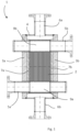
Figure 1 presents an exemplary embodiment of a structure of Plate and Shell heat exchanger, to which the improved end structure according to the present invention can be adapted. Aplate heat exchanger 1 comprises aplate pack 2 and an outer casing surrounding the plate pack, which outer casing comprises afirst end plate 3a and asecond end plate 3b and ashell 4 connecting said first and second end plates. Aplate pack 2 has been formed ofheat exchanger plates Figures 2-4 , the heat exchange plates have at least two openings and arranged on top of each other, wherein the plate pack comprises a first end and a second end in the length/height direction of the plate pack, and the plate pack comprises a firstsupport end plate 7a arranged on the first end of the plate pack and a secondsupport end plate 7b arranged on the second end of the plate pack. Theflow passages plate pack 2 are formed of the openings of the heat exchange plates arranged on top of each other. The plate heat exchanger further comprises aninlet connection tube 5a and anoutlet connection tube 5b for a first heat exchange medium, which are arranged through the end plates of the outer casing and arranged in connection with theflow passages -
Figure 2 presents a structure of the end of the plate heat exchanger according to an embodiment, which comprises a flexible structure 9 between the firstsupport end plate 7a of the plate pack and the first end plate of theouter casing 3a. -
Figure 3 presents a structure of the end of the plate heat exchanger according to an embodiment, which comprises aheating channel 10. Theheating channel 10 is arranged between the firstsupport end plate 7a of the plate pack and thefirst end plate 3a of the outer casing. Theheating channel 10 is also arranged to circulate theinlet connection tube 5a. Theheating channel 10 can be arranged to be in connection with the inside of the shell, wherein a heating fluid or medium to be flown in the heating channel is same fluid or medium which flows inside the shell. -
Figure 4 presents a structure of the end of the plate heat exchanger according to an embodiment of the invention, which comprises aninner tube 11, which is arranged inside theinlet connection tube 5a for the first heat exchange medium. Theinner tube 11 elongates at least partly inside theflow passage 9a of the plate pack. In a typical embodiment according to the present invention, an end of theinner tube 11 is attached to theinlet connection tube 5a. Inside the flow channel of the plate pack, theinner tube 11 is attached to the plate pack by a gasket or anelastic structure 12 arranged around theinner tube 11. A gasket or anelastic structure 12 is typically arranged to the structure around the inner tube so that it also closes the first flow channels between the plate pairs of the plate pack. According to an embodiment presented inFigure 4 , theinner tube 11 comprisesopenings
Claims (4)
- A plate heat exchanger (1), which comprises- a plate pack (2) formed of heat exchanger plates (8, 8', 8") having at least two openings and arranged on top of each other, wherein the plate pack comprises a first end and a second end in the length direction of the plate pack, and which plate pack comprises a first support end plate (7a) arranged on the first end of the plate pack, a second support end plate (7b) arranged on the second end of the plate pack, and flow passages (9a, 9b) for a first heat exchange medium inside the plate pack are formed of the openings of the heat exchange plates (8, 8', 8") arranged on top of each other,- an outer casing surrounding the plate pack, which outer casing comprises a first end plate (3a) and a second end plate (3b) and a shell (4) connecting said first and second end plates,- inlet connection tube (5a) and outlet connection tube (5b) for a first heat exchange medium, arranged through an end plate (3a, 3b) of the outer casing and arranged in connection with the flow passages (9a, 9b) of the plate pack, and- inlet connection tube (6a) and outlet connection tube (6b) for a second heat exchange medium arranged through the outer casing and arranged in connection with the inside of the outer casing, i.e. with the outside of the plate pack,wherein
the inlet connection tube (5a) of the first heat exchange medium is arranged through the first end plate (3a) of the outer casing and in connection with the first support end plate (7a) of the plate pack, and characterized in that the plate heat exchanger further comprises an inner tube (11), which is arranged inside the inlet connection tube (5a) of the first heat exchange medium and which elongates at least partly inside the flow passage (9a) of the plate pack and comprises openings (13, 13', 13") which form flow channels into the flow channels inside the plate pack, and 1 - 5 of the first flow channels inside the plate pack are closed, seen from the direction of the inlet connection tube (5a) of the first heat exchange medium, and the inner tube (11) is attached to the plate pack (2) inside the flow channel (9a) of the plate pack by a gasket or an elastic structure arranged around the inner tube. - The plate heat exchanger according to claim 1, characterized in that an end of the inner tube (11) is attached to the inlet connection tube (5a) of the first heat exchange medium.
- The plate heat exchanger according to claim 1 or 2, characterized in that the plate heat exchanger is liquefied natural gas (LNG) vaporizer.
- Use of the plate heat exchanger according to any of the preceding claims 1-3 as liquefied natural gas (LNG) vaporizer.
Priority Applications (1)
| Application Number | Priority Date | Filing Date | Title |
|---|---|---|---|
| RS20250006A RS66374B1 (en) | 2019-12-12 | 2020-12-11 | PLATE HEAT EXCHANGER AND ITS APPLICATION AS EVAPORATOR FOR LIQUID NATURAL GAS |
Applications Claiming Priority (2)
| Application Number | Priority Date | Filing Date | Title |
|---|---|---|---|
| FI20196074A FI130245B (en) | 2019-12-12 | 2019-12-12 | Plate heat exchanger and its use as liquefied natural gas vaporizer |
| PCT/FI2020/050830 WO2021116534A1 (en) | 2019-12-12 | 2020-12-11 | Plate heat exchanger and its use as liquefied natural gas vaporizer |
Publications (3)
| Publication Number | Publication Date |
|---|---|
| EP4073449A1 EP4073449A1 (en) | 2022-10-19 |
| EP4073449B1 true EP4073449B1 (en) | 2024-10-09 |
| EP4073449C0 EP4073449C0 (en) | 2024-10-09 |
Family
ID=73855499
Family Applications (1)
| Application Number | Title | Priority Date | Filing Date |
|---|---|---|---|
| EP20828028.9A Active EP4073449B1 (en) | 2019-12-12 | 2020-12-11 | Plate heat exchanger and its use as liquefied natural gas vaporizer |
Country Status (9)
| Country | Link |
|---|---|
| US (1) | US12259197B2 (en) |
| EP (1) | EP4073449B1 (en) |
| JP (1) | JP7695937B2 (en) |
| KR (1) | KR20220106756A (en) |
| CN (1) | CN114761751A (en) |
| CA (1) | CA3158590A1 (en) |
| FI (1) | FI130245B (en) |
| RS (1) | RS66374B1 (en) |
| WO (1) | WO2021116534A1 (en) |
Family Cites Families (21)
| Publication number | Priority date | Publication date | Assignee | Title |
|---|---|---|---|---|
| JPS62242791A (en) | 1986-04-16 | 1987-10-23 | Ishikawajima Harima Heavy Ind Co Ltd | Plate fin type heat exchanger |
| US4917181A (en) * | 1988-08-04 | 1990-04-17 | Textron Lycoming | Segmented annular recuperator and method |
| JP2936775B2 (en) * | 1991-04-05 | 1999-08-23 | 株式会社デンソー | Heat exchanger |
| JPH06257983A (en) | 1993-03-09 | 1994-09-16 | Nissan Motor Co Ltd | Stacked heat exchanger |
| US5368095A (en) * | 1993-03-11 | 1994-11-29 | Avco Corporation | Gas turbine recuperator support |
| JP3041753B2 (en) * | 1994-02-16 | 2000-05-15 | 株式会社日立製作所 | Plate heat exchanger |
| JP3936088B2 (en) * | 1998-12-08 | 2007-06-27 | 大阪瓦斯株式会社 | Three-fluid plate heat exchanger and method for manufacturing the same |
| US7017656B2 (en) * | 2001-05-24 | 2006-03-28 | Honeywell International, Inc. | Heat exchanger with manifold tubes for stiffening and load bearing |
| US7004237B2 (en) * | 2001-06-29 | 2006-02-28 | Delaware Capital Formation, Inc. | Shell and plate heat exchanger |
| US20030010483A1 (en) * | 2001-07-13 | 2003-01-16 | Yasuo Ikezaki | Plate type heat exchanger |
| US6892797B2 (en) * | 2001-12-21 | 2005-05-17 | Honeywell International, Inc. | Heat exchanger with biased and expandable core support structure |
| US7036562B2 (en) * | 2002-02-26 | 2006-05-02 | Honeywell International, Inc. | Heat exchanger with core and support structure coupling for reduced thermal stress |
| DE10392905T5 (en) * | 2002-07-11 | 2005-08-25 | Honda Giken Kogyo K.K. | Evaporator |
| US7506683B2 (en) * | 2004-05-21 | 2009-03-24 | Valeo, Inc. | Multi-type fins for multi-exchangers |
| US20080223565A1 (en) * | 2007-03-13 | 2008-09-18 | Kaori Heat Treatment Co., Ltd. | Flow distributor for heat transfer device |
| ATE553349T1 (en) | 2008-12-16 | 2012-04-15 | Alfa Laval Corp Ab | HEAT EXCHANGER |
| FI124230B (en) | 2012-05-28 | 2014-05-15 | Vahterus Oy | PROCEDURES AND ARRANGEMENTS FOR REPAIRING A HEAT EXCHANGE PLATE PACKAGE AND PLATE HEAT EXCHANGER |
| DE102012011936A1 (en) | 2012-06-18 | 2013-12-19 | Api Schmidt-Bretten Gmbh & Co. Kg | Plate heat exchangers |
| DE112014004486B4 (en) | 2013-09-30 | 2022-10-06 | Dana Canada Corporation | Heat exchanger with integrated inlet/outlet coaxial tube |
| US10544902B2 (en) * | 2014-12-02 | 2020-01-28 | Halliburton Energy Services, Inc. | Liquefied natural gas vaporizer for downhole oil or gas applications |
| CA3010728A1 (en) * | 2016-02-01 | 2017-08-10 | Dana Canada Corporation | Structurally integral heat exchanger within a plastic housing |
-
2019
- 2019-12-12 FI FI20196074A patent/FI130245B/en active
-
2020
- 2020-12-11 US US17/784,353 patent/US12259197B2/en active Active
- 2020-12-11 CN CN202080085748.XA patent/CN114761751A/en active Pending
- 2020-12-11 KR KR1020227017394A patent/KR20220106756A/en active Pending
- 2020-12-11 RS RS20250006A patent/RS66374B1/en unknown
- 2020-12-11 CA CA3158590A patent/CA3158590A1/en active Pending
- 2020-12-11 WO PCT/FI2020/050830 patent/WO2021116534A1/en not_active Ceased
- 2020-12-11 EP EP20828028.9A patent/EP4073449B1/en active Active
- 2020-12-11 JP JP2022535789A patent/JP7695937B2/en active Active
Also Published As
| Publication number | Publication date |
|---|---|
| FI130245B (en) | 2023-05-05 |
| CA3158590A1 (en) | 2021-06-17 |
| US12259197B2 (en) | 2025-03-25 |
| FI20196074A1 (en) | 2021-06-13 |
| KR20220106756A (en) | 2022-07-29 |
| EP4073449C0 (en) | 2024-10-09 |
| US20230046534A1 (en) | 2023-02-16 |
| JP2023505893A (en) | 2023-02-13 |
| JP7695937B2 (en) | 2025-06-19 |
| RS66374B1 (en) | 2025-02-28 |
| CN114761751A (en) | 2022-07-15 |
| EP4073449A1 (en) | 2022-10-19 |
| WO2021116534A1 (en) | 2021-06-17 |
Similar Documents
| Publication | Publication Date | Title |
|---|---|---|
| CN105102800B (en) | Gas prints circuit heat exchanger | |
| US9897389B2 (en) | Heat exchanger | |
| EP3220088B1 (en) | Stacked type fluid heater and method of heating fluid with stacked type fluid heater | |
| US5797449A (en) | Heat exchanger | |
| US10060680B2 (en) | Heat exchanger and method of making the same | |
| US10066874B2 (en) | Plate heat exchanger and method for constructing multiple passes in the plate heat exchanger | |
| US11060795B2 (en) | Double tube for heat exchange | |
| US20190137197A1 (en) | Printed circuit-type heat exchanger having integral structure | |
| US20140305620A1 (en) | Plate heat exchanger and method for manufacturing of a plate heat exchanger | |
| JP2001116483A (en) | Plate heat-exchanger | |
| KR20200088611A (en) | Plate type Heat Exchanger for Cryogenic Liquefied Gas | |
| EP2225524A2 (en) | Water vaporizer with intermediate steam superheating pass | |
| EP3587990B1 (en) | Header box for heat exchanger with thermal decoupling | |
| US20210262697A1 (en) | Heat exchanger and water heating device including the same | |
| EP2199723B1 (en) | Heat exchanger | |
| EP4073449B1 (en) | Plate heat exchanger and its use as liquefied natural gas vaporizer | |
| EP2438381B1 (en) | A plate heat exchanger | |
| US20070000652A1 (en) | Heat exchanger with dimpled tube surfaces | |
| JP4933125B2 (en) | Shell and tube heat exchanger | |
| WO2020013319A1 (en) | Vaporizer | |
| US20170122667A1 (en) | Block-in-shell heat exchanger | |
| KR200431393Y1 (en) | Tube Multistage Assembly Heat Exchanger | |
| JP6548927B2 (en) | Heat exchanger and liquefied gas evaporator | |
| KR20230106860A (en) | Heat exchange direct water purifier with double pipe | |
| JP2010085007A (en) | Heat exchanger |
Legal Events
| Date | Code | Title | Description |
|---|---|---|---|
| STAA | Information on the status of an ep patent application or granted ep patent |
Free format text: STATUS: UNKNOWN |
|
| STAA | Information on the status of an ep patent application or granted ep patent |
Free format text: STATUS: THE INTERNATIONAL PUBLICATION HAS BEEN MADE |
|
| PUAI | Public reference made under article 153(3) epc to a published international application that has entered the european phase |
Free format text: ORIGINAL CODE: 0009012 |
|
| STAA | Information on the status of an ep patent application or granted ep patent |
Free format text: STATUS: REQUEST FOR EXAMINATION WAS MADE |
|
| 17P | Request for examination filed |
Effective date: 20220620 |
|
| AK | Designated contracting states |
Kind code of ref document: A1 Designated state(s): AL AT BE BG CH CY CZ DE DK EE ES FI FR GB GR HR HU IE IS IT LI LT LU LV MC MK MT NL NO PL PT RO RS SE SI SK SM TR |
|
| DAV | Request for validation of the european patent (deleted) | ||
| DAX | Request for extension of the european patent (deleted) | ||
| STAA | Information on the status of an ep patent application or granted ep patent |
Free format text: STATUS: EXAMINATION IS IN PROGRESS |
|
| 17Q | First examination report despatched |
Effective date: 20231122 |
|
| GRAP | Despatch of communication of intention to grant a patent |
Free format text: ORIGINAL CODE: EPIDOSNIGR1 |
|
| STAA | Information on the status of an ep patent application or granted ep patent |
Free format text: STATUS: GRANT OF PATENT IS INTENDED |
|
| INTG | Intention to grant announced |
Effective date: 20240618 |
|
| GRAS | Grant fee paid |
Free format text: ORIGINAL CODE: EPIDOSNIGR3 |
|
| GRAA | (expected) grant |
Free format text: ORIGINAL CODE: 0009210 |
|
| STAA | Information on the status of an ep patent application or granted ep patent |
Free format text: STATUS: THE PATENT HAS BEEN GRANTED |
|
| AK | Designated contracting states |
Kind code of ref document: B1 Designated state(s): AL AT BE BG CH CY CZ DE DK EE ES FI FR GB GR HR HU IE IS IT LI LT LU LV MC MK MT NL NO PL PT RO RS SE SI SK SM TR |
|
| REG | Reference to a national code |
Ref country code: CH Ref legal event code: EP |
|
| REG | Reference to a national code |
Ref country code: DE Ref legal event code: R096 Ref document number: 602020039242 Country of ref document: DE |
|
| REG | Reference to a national code |
Ref country code: IE Ref legal event code: FG4D |
|
| U01 | Request for unitary effect filed |
Effective date: 20241028 |
|
| U07 | Unitary effect registered |
Designated state(s): AT BE BG DE DK EE FI FR IT LT LU LV MT NL PT RO SE SI Effective date: 20241107 |
|
| U20 | Renewal fee for the european patent with unitary effect paid |
Year of fee payment: 5 Effective date: 20250115 |
|
| PG25 | Lapsed in a contracting state [announced via postgrant information from national office to epo] |
Ref country code: IS Free format text: LAPSE BECAUSE OF FAILURE TO SUBMIT A TRANSLATION OF THE DESCRIPTION OR TO PAY THE FEE WITHIN THE PRESCRIBED TIME-LIMIT Effective date: 20250209 Ref country code: HR Free format text: LAPSE BECAUSE OF FAILURE TO SUBMIT A TRANSLATION OF THE DESCRIPTION OR TO PAY THE FEE WITHIN THE PRESCRIBED TIME-LIMIT Effective date: 20241009 |
|
| PG25 | Lapsed in a contracting state [announced via postgrant information from national office to epo] |
Ref country code: ES Free format text: LAPSE BECAUSE OF FAILURE TO SUBMIT A TRANSLATION OF THE DESCRIPTION OR TO PAY THE FEE WITHIN THE PRESCRIBED TIME-LIMIT Effective date: 20241009 |
|
| PG25 | Lapsed in a contracting state [announced via postgrant information from national office to epo] |
Ref country code: NO Free format text: LAPSE BECAUSE OF FAILURE TO SUBMIT A TRANSLATION OF THE DESCRIPTION OR TO PAY THE FEE WITHIN THE PRESCRIBED TIME-LIMIT Effective date: 20250109 |
|
| PG25 | Lapsed in a contracting state [announced via postgrant information from national office to epo] |
Ref country code: GR Free format text: LAPSE BECAUSE OF FAILURE TO SUBMIT A TRANSLATION OF THE DESCRIPTION OR TO PAY THE FEE WITHIN THE PRESCRIBED TIME-LIMIT Effective date: 20250110 |
|
| PG25 | Lapsed in a contracting state [announced via postgrant information from national office to epo] |
Ref country code: PL Free format text: LAPSE BECAUSE OF FAILURE TO SUBMIT A TRANSLATION OF THE DESCRIPTION OR TO PAY THE FEE WITHIN THE PRESCRIBED TIME-LIMIT Effective date: 20241009 |
|
| PG25 | Lapsed in a contracting state [announced via postgrant information from national office to epo] |
Ref country code: SM Free format text: LAPSE BECAUSE OF FAILURE TO SUBMIT A TRANSLATION OF THE DESCRIPTION OR TO PAY THE FEE WITHIN THE PRESCRIBED TIME-LIMIT Effective date: 20241009 |
|
| PG25 | Lapsed in a contracting state [announced via postgrant information from national office to epo] |
Ref country code: MC Free format text: LAPSE BECAUSE OF FAILURE TO SUBMIT A TRANSLATION OF THE DESCRIPTION OR TO PAY THE FEE WITHIN THE PRESCRIBED TIME-LIMIT Effective date: 20241009 |
|
| PG25 | Lapsed in a contracting state [announced via postgrant information from national office to epo] |
Ref country code: SK Free format text: LAPSE BECAUSE OF FAILURE TO SUBMIT A TRANSLATION OF THE DESCRIPTION OR TO PAY THE FEE WITHIN THE PRESCRIBED TIME-LIMIT Effective date: 20241009 |
|
| PG25 | Lapsed in a contracting state [announced via postgrant information from national office to epo] |
Ref country code: CZ Free format text: LAPSE BECAUSE OF FAILURE TO SUBMIT A TRANSLATION OF THE DESCRIPTION OR TO PAY THE FEE WITHIN THE PRESCRIBED TIME-LIMIT Effective date: 20241009 |
|
| REG | Reference to a national code |
Ref country code: CH Ref legal event code: PL |
|
| PLBE | No opposition filed within time limit |
Free format text: ORIGINAL CODE: 0009261 |
|
| STAA | Information on the status of an ep patent application or granted ep patent |
Free format text: STATUS: NO OPPOSITION FILED WITHIN TIME LIMIT |
|
| 26N | No opposition filed |
Effective date: 20250710 |
|
| GBPC | Gb: european patent ceased through non-payment of renewal fee |
Effective date: 20250109 |
|
| PG25 | Lapsed in a contracting state [announced via postgrant information from national office to epo] |
Ref country code: GB Free format text: LAPSE BECAUSE OF NON-PAYMENT OF DUE FEES Effective date: 20250109 |
|
| PG25 | Lapsed in a contracting state [announced via postgrant information from national office to epo] |
Ref country code: CH Free format text: LAPSE BECAUSE OF NON-PAYMENT OF DUE FEES Effective date: 20241231 |
|
| PG25 | Lapsed in a contracting state [announced via postgrant information from national office to epo] |
Ref country code: IE Free format text: LAPSE BECAUSE OF NON-PAYMENT OF DUE FEES Effective date: 20241211 |
|
| U20 | Renewal fee for the european patent with unitary effect paid |
Year of fee payment: 6 Effective date: 20251216 |
|
| PGFP | Annual fee paid to national office [announced via postgrant information from national office to epo] |
Ref country code: RS Payment date: 20251113 Year of fee payment: 6 |