EP4073375B1 - Blade pitch controller for a wind turbine - Google Patents
Blade pitch controller for a wind turbine Download PDFInfo
- Publication number
- EP4073375B1 EP4073375B1 EP20899949.0A EP20899949A EP4073375B1 EP 4073375 B1 EP4073375 B1 EP 4073375B1 EP 20899949 A EP20899949 A EP 20899949A EP 4073375 B1 EP4073375 B1 EP 4073375B1
- Authority
- EP
- European Patent Office
- Prior art keywords
- wind turbine
- blade pitch
- controller
- filtering system
- estimates
- Prior art date
- Legal status (The legal status is an assumption and is not a legal conclusion. Google has not performed a legal analysis and makes no representation as to the accuracy of the status listed.)
- Active
Links
Images




Classifications
-
- F—MECHANICAL ENGINEERING; LIGHTING; HEATING; WEAPONS; BLASTING
- F03—MACHINES OR ENGINES FOR LIQUIDS; WIND, SPRING, OR WEIGHT MOTORS; PRODUCING MECHANICAL POWER OR A REACTIVE PROPULSIVE THRUST, NOT OTHERWISE PROVIDED FOR
- F03D—WIND MOTORS
- F03D13/00—Assembly, mounting or commissioning of wind motors; Arrangements specially adapted for transporting wind motor components
- F03D13/20—Arrangements for mounting or supporting wind motors; Masts or towers for wind motors
- F03D13/25—Arrangements for mounting or supporting wind motors; Masts or towers for wind motors specially adapted for offshore installation
-
- F—MECHANICAL ENGINEERING; LIGHTING; HEATING; WEAPONS; BLASTING
- F03—MACHINES OR ENGINES FOR LIQUIDS; WIND, SPRING, OR WEIGHT MOTORS; PRODUCING MECHANICAL POWER OR A REACTIVE PROPULSIVE THRUST, NOT OTHERWISE PROVIDED FOR
- F03D—WIND MOTORS
- F03D7/00—Controlling wind motors
- F03D7/02—Controlling wind motors the wind motors having rotation axis substantially parallel to the air flow entering the rotor
- F03D7/022—Adjusting aerodynamic properties of the blades
- F03D7/0224—Adjusting blade pitch
-
- F—MECHANICAL ENGINEERING; LIGHTING; HEATING; WEAPONS; BLASTING
- F03—MACHINES OR ENGINES FOR LIQUIDS; WIND, SPRING, OR WEIGHT MOTORS; PRODUCING MECHANICAL POWER OR A REACTIVE PROPULSIVE THRUST, NOT OTHERWISE PROVIDED FOR
- F03D—WIND MOTORS
- F03D7/00—Controlling wind motors
- F03D7/02—Controlling wind motors the wind motors having rotation axis substantially parallel to the air flow entering the rotor
- F03D7/0296—Controlling wind motors the wind motors having rotation axis substantially parallel to the air flow entering the rotor to prevent, counteract or reduce noise emissions
-
- F—MECHANICAL ENGINEERING; LIGHTING; HEATING; WEAPONS; BLASTING
- F03—MACHINES OR ENGINES FOR LIQUIDS; WIND, SPRING, OR WEIGHT MOTORS; PRODUCING MECHANICAL POWER OR A REACTIVE PROPULSIVE THRUST, NOT OTHERWISE PROVIDED FOR
- F03D—WIND MOTORS
- F03D7/00—Controlling wind motors
- F03D7/02—Controlling wind motors the wind motors having rotation axis substantially parallel to the air flow entering the rotor
- F03D7/0298—Controlling wind motors the wind motors having rotation axis substantially parallel to the air flow entering the rotor to prevent, counteract or reduce vibrations
- F03D7/0302—Controlling wind motors the wind motors having rotation axis substantially parallel to the air flow entering the rotor to prevent, counteract or reduce vibrations of the tower
-
- F—MECHANICAL ENGINEERING; LIGHTING; HEATING; WEAPONS; BLASTING
- F03—MACHINES OR ENGINES FOR LIQUIDS; WIND, SPRING, OR WEIGHT MOTORS; PRODUCING MECHANICAL POWER OR A REACTIVE PROPULSIVE THRUST, NOT OTHERWISE PROVIDED FOR
- F03D—WIND MOTORS
- F03D7/00—Controlling wind motors
- F03D7/02—Controlling wind motors the wind motors having rotation axis substantially parallel to the air flow entering the rotor
- F03D7/04—Automatic control; Regulation
- F03D7/042—Automatic control; Regulation by means of an electrical or electronic controller
- F03D7/043—Automatic control; Regulation by means of an electrical or electronic controller characterised by the type of control logic
- F03D7/046—Automatic control; Regulation by means of an electrical or electronic controller characterised by the type of control logic with learning or adaptive control, e.g. self-tuning, fuzzy logic or neural network
-
- F—MECHANICAL ENGINEERING; LIGHTING; HEATING; WEAPONS; BLASTING
- F05—INDEXING SCHEMES RELATING TO ENGINES OR PUMPS IN VARIOUS SUBCLASSES OF CLASSES F01-F04
- F05B—INDEXING SCHEME RELATING TO WIND, SPRING, WEIGHT, INERTIA OR LIKE MOTORS, TO MACHINES OR ENGINES FOR LIQUIDS COVERED BY SUBCLASSES F03B, F03D AND F03G
- F05B2240/00—Components
- F05B2240/90—Mounting on supporting structures or systems
- F05B2240/95—Mounting on supporting structures or systems offshore
-
- F—MECHANICAL ENGINEERING; LIGHTING; HEATING; WEAPONS; BLASTING
- F05—INDEXING SCHEMES RELATING TO ENGINES OR PUMPS IN VARIOUS SUBCLASSES OF CLASSES F01-F04
- F05B—INDEXING SCHEME RELATING TO WIND, SPRING, WEIGHT, INERTIA OR LIKE MOTORS, TO MACHINES OR ENGINES FOR LIQUIDS COVERED BY SUBCLASSES F03B, F03D AND F03G
- F05B2270/00—Control
- F05B2270/30—Control parameters, e.g. input parameters
- F05B2270/328—Blade pitch angle
-
- F—MECHANICAL ENGINEERING; LIGHTING; HEATING; WEAPONS; BLASTING
- F05—INDEXING SCHEMES RELATING TO ENGINES OR PUMPS IN VARIOUS SUBCLASSES OF CLASSES F01-F04
- F05B—INDEXING SCHEME RELATING TO WIND, SPRING, WEIGHT, INERTIA OR LIKE MOTORS, TO MACHINES OR ENGINES FOR LIQUIDS COVERED BY SUBCLASSES F03B, F03D AND F03G
- F05B2270/00—Control
- F05B2270/30—Control parameters, e.g. input parameters
- F05B2270/342—Wave conditions, e.g. amplitude, frequency or direction
-
- Y—GENERAL TAGGING OF NEW TECHNOLOGICAL DEVELOPMENTS; GENERAL TAGGING OF CROSS-SECTIONAL TECHNOLOGIES SPANNING OVER SEVERAL SECTIONS OF THE IPC; TECHNICAL SUBJECTS COVERED BY FORMER USPC CROSS-REFERENCE ART COLLECTIONS [XRACs] AND DIGESTS
- Y02—TECHNOLOGIES OR APPLICATIONS FOR MITIGATION OR ADAPTATION AGAINST CLIMATE CHANGE
- Y02E—REDUCTION OF GREENHOUSE GAS [GHG] EMISSIONS, RELATED TO ENERGY GENERATION, TRANSMISSION OR DISTRIBUTION
- Y02E10/00—Energy generation through renewable energy sources
- Y02E10/70—Wind energy
- Y02E10/72—Wind turbines with rotation axis in wind direction
-
- Y—GENERAL TAGGING OF NEW TECHNOLOGICAL DEVELOPMENTS; GENERAL TAGGING OF CROSS-SECTIONAL TECHNOLOGIES SPANNING OVER SEVERAL SECTIONS OF THE IPC; TECHNICAL SUBJECTS COVERED BY FORMER USPC CROSS-REFERENCE ART COLLECTIONS [XRACs] AND DIGESTS
- Y02—TECHNOLOGIES OR APPLICATIONS FOR MITIGATION OR ADAPTATION AGAINST CLIMATE CHANGE
- Y02E—REDUCTION OF GREENHOUSE GAS [GHG] EMISSIONS, RELATED TO ENERGY GENERATION, TRANSMISSION OR DISTRIBUTION
- Y02E10/00—Energy generation through renewable energy sources
- Y02E10/70—Wind energy
- Y02E10/727—Offshore wind turbines
Definitions
- the present invention relates to the field of rotor blade pitch control for fixed foundation offshore wind turbines.
- FIG. 1 A schematic diagram showing an example of a typical fixed foundation offshore wind turbine is shown in Fig. 1 .
- a fixed foundation offshore wind turbine 1 typically comprises an elongate tower 5, with a nacelle 4 and a rotor 2 attached to the upper end of the tower 5.
- the generator and its associated electronics are usually located in the nacelle 4.
- the rotor 2 comprises a plurality of (e.g. two or three) blades 3.
- the wind turbine 1 is fixed, via a foundation 6 which is connected to the lower end of the tower 5, to the seabed 7 in an offshore location.
- offshore simply means that the foundation of the wind turbine is surrounded by water. This could be, and typically is, sea water, for example.
- This method is based on a blade pitch controller comprising a tower feedback loop consisting of a state estimator and a reference model, which both use low fidelity models of the wind turbine system, with the purpose of dividing or separating the wind and wave induced motions, and providing stiffness based on the wave induced part of the motion, and providing damping based on the overall velocity of the tower.
- the main advantages of the increased stiffness are that the first bending frequency is moved further away from the wave excitation frequencies, and that it achieves a wider frequency range of effectiveness than from providing only increased damping. This is believed to be of greater importance for large offshore wind turbines (6-10 MW and beyond, for example) where wave loads often dominate in terms of fatigue utilisation. The largest improvement compared to controllers providing increased damping only was found at high sea states.
- WO 2018/210390 A1 discloses control of a wind turbine where nacelle vibration is reduced by use of blade pitching or generator torque modulation.
- the invention provides a blade pitch controller which adjusts the blade pitch so as to provide effective stiffness to the wind turbine in response to motion of the wind turbine above a filter frequency of the filtering system.
- Using a filtering system allows the effective stiffness of the wind turbine to be increased only in response to motion of the wind turbine which is above a filter frequency of the filtering system, in a relatively simple way. In other words, this mechanism of providing increased stiffness can be applied selectively only in response to wind turbine motion which is above a certain frequency.
- the filter frequency is less than 0.2Hz.
- the filter frequency is preferably below the wave frequency range, which is usually around 0.2 - 0.05 Hz.
- the tower feedback loop may operate to provide additional effective stiffness to all measured dynamic motion of the tower above a filter frequency of the filtering system and beneath the bandwidth of the blade pitch mechanism, this may exclude any influence due to, for example, a wind turbine tower bending due to a steady wind or gentle changes in the wind (zero or low frequency) but may act on motion caused by the relatively high frequency of waves hitting the tower.
- the filtering system comprises a high-pass filter. This is used to filter out wind turbine motion which is below the filter frequency of the high-pass filter.
- the filter frequency of the filtering system referred to above corresponds to the filter frequency of the high-pass filter.
- the tower feedback loop is preferably arranged to control wind turbine blade pitch so as to provide additional effective stiffness and damping to the wind turbine in response to motion of the wind turbine which is within a bandwidth of a blade pitch actuator.
- a time constant for the blade pitch actuator may vary with turbine model and size. However, a typical range could be around 0.2 - 2 seconds.
- the position and/or velocity measurements or estimates may be provided from direct measurements or they could be calculated based on position, velocity and/or acceleration measurements.
- the position and/or velocity measurements or estimates may be provided from one or more (motion) sensors located on the wind turbine, and preferably located on a tower, platform deck or foundation of the wind turbine. Preferably, the one or more sensors are located at or near a water line on the wind turbine.
- the filtering system outputs filtered position and/or velocity measurements or estimates of the wind turbine. Such measurements are then used (in the tower feedback loop) to determine a blade pitch adjustment.
- the filtering system is arranged to filter the position and velocity measurements of the wind turbine differently, for example with different filters.
- the filtering system is preferably arranged to filter out static and/or quasi-static (e.g. very slow) motion. This may be caused by constant and/or slow changes in wind, for example, resulting in low-frequency wind-induced motion.
- the filtering system is arranged to filter out motion at a blade passing frequency.
- the filtering system may be arranged to filter out motion at the 3P frequency.
- the filtering system may be arranged to filter out motion at the 2P frequency.
- the 3P frequency could be in the range of 0.2 - 0.6 Hz, and/or the 2P frequency could be in the range 0.15-0.5 Hz, for example.
- the filtering system may be arranged to filter out noise such as high frequency noise or responses. This could be performed with a low-pass filter, for example (preferably with a sufficiently high filter frequency such as 0.5 Hz).
- the low-pass filter could be a second order Butterworth low-pass filter.
- the method comprises using a blade pitch controller as described above (with any of its optional or preferred features).
- the method may comprise controlling wind turbine blade pitch so as to provide additional effective stiffness to the wind turbine in response to motion of the wind turbine within a bandwidth of a blade pitch actuator.
- the wind turbine preferably comprises one or more motion sensors as described above.
- a tower feedback controller for a blade pitch controller for a wind turbine wherein the tower feedback controller comprises a filtering system.
- the filtering system comprises a high-pass filter with a filter frequency of less than 0.2Hz.
- the filtering system is arranged to receive at least one position or velocity measurements or estimates of the wind turbine as input and to output at least one filtered position or velocity measurements or estimates of the wind turbine.
- the feedback controller is arranged to receive the output at least one filtered position or velocity measurements or estimates of the wind turbine from the filtering system and to output a blade pitch reference signal determined from the filtered at least one position or velocity measurements or estimates of the wind turbine to a nominal control system arranged to control a blade pitch of the wind turbine in order to optimise power production, wherein the blade pitch reference signal is an adjustment which is added to a nominal blade pitch reference signal provided from a basic controller in the nominal control system, such that tower feedback controller is arranged to control wind turbine blade pitch so as to provide additional effective stiffness to the wind turbine in response to motion of the wind turbine above the filter frequency of the high-pass filter of the filtering system.
- the tower feedback controller and preferably also its filtering system, is preferably as described above.
- the blade pitch controller 10 which is described in more detail in Smilden, 2018, consists of two parts: a nominal control system 11 and a tower feedback loop 12.
- the nominal control system 11 comprises a basic controller 13 which receives signals from and sends signals to an offshore wind turbine 14.
- the basic controller 13 of the nominal control system 11 adjusts the blade pitch of the wind turbine in order to optimise power production.
- the nominal control system 11 is combined with a tower feedback loop 12, which adjusts the blade pitch of the wind turbine to reduce or minimise tower motions.
- the tower feedback loop 12 receives measurements (signals) directly from the offshore wind turbine 14.
- the main objective of the tower feedback loop 12 is to reduce wave-induced fatigue loads in the tower 5.
- Proportional-derivative collective pitch control is employed to provide the tower 5 with additional damping and stiffness in the fore-aft direction.
- Proportional action on the tower displacement with a zero reference input would introduce a steady-state rotor speed error. Therefore, a reference model 16 is employed to produce a non-zero reference trajectory representing the wind-induced tower displacement.
- the tower feedback loop 12 only provides stiffness against wave-induced tower displacements in a frequency range about the frequencies of significant turbulent wind variations. Typically, information about the tower displacements is not available with standard wind turbine measurements.
- the reference model requires information about the rotor wide effective wind speed, which cannot be measured directly.
- a state estimator 15 is required in the tower feedback look 12 to determine (or estimate) these variables.
- a discrete-time extended Kalman filter is formulated to calculate the required state estimates.
- a feedback controller 17 receives the outputs from the state estimator 15 and reference model 16, and feeds this back to the wind turbine 14 in combination with the output from the basic controller 13.
- the tower feedback loop 12 operates in such a way that stiffness is only increased in response to wave induced motion (as opposed to wind-induced motion). This is because there will normally be a degree of wind-induced tower displacement - i.e. the tower will bend in the wind (and stay bent to some degree as long as the wind does not change).
- the state estimator 15 serves to estimate the tower motions and the reference model 16 provides a tower displacement value (which is not or cannot be directly measured) which can be subtracted so that the normal wind-induced displacement does not cause an error.
- the tower feedback loop 12 determines what the wind turbine movements are relative to an actual bent position (caused by the wind) rather than relative to an upright position (which the tower may not necessarily be in).
- the blade pitch controller 20 of the present invention provides a simplified and improved blade pitch controller compared with that illustrated in Fig. 2 .
- the nominal control system 11 is unchanged from that of Fig. 2 .
- a new tower feedback loop 22 is provided, instead of the tower feedback loop 12 of the controller 10.
- the tower feedback loop 22 contains a filtering system 25 instead of the state estimator 15 and reference model 16.
- the filtering system 25 comprises a high-pass filter and operates to provide additional effective stiffness to the wind turbine in response to all measured dynamic motion of the tower above the filter frequency of the high pass filter that is within the bandwidth of the blade pitch actuator, i.e. in response to both wave- and wind-induced motion.
- the tower feedback loop 12 provides stiffness only to the wave-induced part of the dynamic motions of the tower 5.
- the filtering system 25 operates to allow provision of additional effective stiffness to all measured dynamic motion of the tower above the filter frequency of the high pass filter that is within the bandwidth of the blade pitch actuator, this will exclude any influence due to the tower 5 bending due to a steady wind or gentle changes in the wind (zero or low frequency) but will act on motion caused by the relatively high frequency of waves hitting the tower 5.
- the tower feedback loop 22 contains a feedback controller 17'.
- the structure of this feedback controller 17' is the same as that of the feedback controller 17 of Fig. 2 .
- Their parameters could also be the same. However, typically, their parameters are not the same as (when) for the feedback controller 17' the motion sensors are located closer to the waterline than for the feedback controller 17.
- the feedback controller 17' outputs a signal ⁇ TFC , which is an additional blade pitch reference signal that is added to the nominal blade pitch reference signal u B from the basic controller 13.
- the output ⁇ TFC from the feedback controller 17 can be expressed as: where K P ⁇ is the proportional gain, and K D ⁇ is the derivative gain.
- F A ⁇ ⁇ ⁇ is implemented as an estimate of the derivative from pitch angle to aerodynamic thrust force: where ⁇ is the rotor speed and ⁇ is the blade pitch angle.
- the x direction with respect to the wind turbine is as indicated in Fig. 1 .
- Filtering is provided by the filtering system 25. Different filtering could be used on the position and velocity measurements and filtering may not be required at all on the ⁇ f 2 ⁇ measurement.
- the filtering applied to the measurements ⁇ and ⁇ could typically be:
- Motion sensors are provided on the wind turbine 1 to measure the position ⁇ and the velocity ⁇ . These sensors are advantageously located near or at the water line 8 (e.g. as opposed to being closer to/at the nacelle 4) in order to better capture wave-induced motion and less wind-induced noise such as the blade passing frequency effect.
- the platform deck (not shown) of an offshore wind turbine 1 could be a practical and advantageous location for such motion sensors.
- the blade pitch controller 20 has a significantly simpler implementation compared to the prior art controller 10 of Fig. 2 , whilst providing very similar results.
- the table below presents a lifetime comparison of a "Basic” controller (i.e. the nominal control system 11) with the blade pitch controller 10 of Fig. 2 (labelled as “Advanced” in the table) and the blade pitch controller 20 of the present invention and shown in Fig. 3 (labelled as “Simplified” in the table). Eleven different controller performance comparison parameters are compared.
- controller performance comparison parameters that are assessed are defined as follows:
- Fig. 5 presents a lifetime comparison of the accumulation of fatigue damage in the wind turbine foundation with the blade pitch controller 20 of the present invention (labelled as “Proposed simplified controller) compared with the prior art blade pitch controller 10 of Fig. 2 (labelled as “Advanced controller”) and the nominal control system 11 (labelled as “Basic control w/o [without] load reduction”).
- the blade pitch controller 20 of the present invention provides similar performance in terms of fatigue reduction as the prior art blade pitch controller 10 of Fig. 2 .
- Figs. 6a-d The results of a simulation illustrating the effectiveness of the blade pitch controller 20 of the present invention compared to conventional damping control are presented in Figs. 6a-d .
- the black line represents the blade pitch controller 20 of the present invention (labelled as “Proposed damping + stiffness controller)
- the blue line represents a prior art conventional damping controller (labelled as “Conventional damping controller”
- the red line represents using just the nominal control system 11 (labelled as "Basic controller w/o [without] load reduction”).
- Fig. 6(b) is a plot of power density measured in deg 2 /Hz as a function of frequency, showing power spectral density of the blades' pitch angle.
- the blade pitch controller 20 of the present invention could also provide additional stiffness for excitation mechanisms other than waves, if their excitation frequency is above the selected high pass filter frequency and within the bandwidth of the blade pitch actuator (and outside the notch filter frequency area if this is applied).
Landscapes
- Engineering & Computer Science (AREA)
- Mechanical Engineering (AREA)
- Sustainable Development (AREA)
- Sustainable Energy (AREA)
- Chemical & Material Sciences (AREA)
- Life Sciences & Earth Sciences (AREA)
- Combustion & Propulsion (AREA)
- General Engineering & Computer Science (AREA)
- Physics & Mathematics (AREA)
- Fluid Mechanics (AREA)
- Artificial Intelligence (AREA)
- Evolutionary Computation (AREA)
- Fuzzy Systems (AREA)
- Mathematical Physics (AREA)
- Software Systems (AREA)
- Wind Motors (AREA)
- Feedback Control In General (AREA)
Description
- The present invention relates to the field of rotor blade pitch control for fixed foundation offshore wind turbines.
- A schematic diagram showing an example of a typical fixed foundation offshore wind turbine is shown in
Fig. 1 . As shown in this figure, a fixed foundationoffshore wind turbine 1 typically comprises anelongate tower 5, with anacelle 4 and arotor 2 attached to the upper end of thetower 5. The generator and its associated electronics are usually located in thenacelle 4. Therotor 2 comprises a plurality of (e.g. two or three)blades 3. Thewind turbine 1 is fixed, via afoundation 6 which is connected to the lower end of thetower 5, to theseabed 7 in an offshore location. - In this context, it should be understood that "offshore" simply means that the foundation of the wind turbine is surrounded by water. This could be, and typically is, sea water, for example.
- It is known to control the pitch of the rotor blades in order to improve performance in wind turbines. For example, blade pitch may be controlled to optimise power output. However, blade pitch may also be controlled for other reasons, such as to reduce vibrations.
- Methods of using collective blade pitch control (i.e. controlling all the rotor blades together by the same amount) to increase the aerodynamic damping of the fore-aft bending modes of fixed foundation offshore wind turbines are well known in the wind energy industry. Increased aerodynamic damping results in reduced fatigue damage in both the tower and the foundation(s) for fixed foundation offshore wind turbines. Such control methods are discussed in Van der Hooft, 2003 and Bossanyi, 2003 (see list of references below). However, these methods are only efficient in a narrow frequency range around the first fore-aft modal frequency.
- More recently, it is also known to use collective blade pitch control to increase the stiffness, as well as the aerodynamic damping, of the fore-aft vibration modes of fixed foundation offshore wind turbines. Such a method is discussed in Smilden, 2018.
- This method is based on a blade pitch controller comprising a tower feedback loop consisting of a state estimator and a reference model, which both use low fidelity models of the wind turbine system, with the purpose of dividing or separating the wind and wave induced motions, and providing stiffness based on the wave induced part of the motion, and providing damping based on the overall velocity of the tower.
- The main advantages of the increased stiffness are that the first bending frequency is moved further away from the wave excitation frequencies, and that it achieves a wider frequency range of effectiveness than from providing only increased damping. This is believed to be of greater importance for large offshore wind turbines (6-10 MW and beyond, for example) where wave loads often dominate in terms of fatigue utilisation. The largest improvement compared to controllers providing increased damping only was found at high sea states.
- The control method disclosed in Smilden, 2018 shows excellent performance with respect to fatigue. However, it is a relatively complex control system, with several low fidelity models implemented in a state estimator and a reference model. This method is also dependent on a mean wind speed measurement, which may be challenging to achieve sufficiently accurately.
- Thus, there is a need for an improved blade pitch control method for fixed foundation offshore wind turbines.
-
WO 2018/210390 A1 discloses control of a wind turbine where nacelle vibration is reduced by use of blade pitching or generator torque modulation. -
EP 2469083 A2 discloses a method for operating a wind turbine erected in a body of water, comprising: measuring a frequency spectrum of vibrations of the wind turbine during operation; identifying at least one periodic component of said measured frequency spectrum, wherein said periodic component is associated with interaction of said body of water and said wind turbine; and, operating at least one controller of said wind turbine so that water-induced vibrations are reduced. - According to a first aspect of the invention, there is provided a blade pitch controller for a fixed foundation offshore wind turbine, the blade pitch controller comprising a nominal control system and a tower feedback loop, wherein the tower feedback loop comprises a filtering system and a feedback controller. The nominal control system is arranged to control a blade pitch of the wind turbine in order to optimise power production. The filtering system comprises a high-pass filter with a filter frequency of less than 0.2 Hz, the filtering system being arranged to receive at least one of position or velocity measurements or estimates of the wind turbine as input and to output at least one filtered position or velocity measurements or estimates of the wind turbine. The feedback controller is arranged to receive at least one of the output filtered position or velocity measurements or estimates of the wind turbine from the filtering system and to output a blade pitch reference signal determined from at least one of the filtered position or velocity measurements or estimates of the wind turbine to the nominal control system, wherein the blade pitch reference signal is an adjustment which is added to a nominal blade pitch reference signal provided from a basic controller in the nominal control system, such that the tower feedback loop is arranged to control wind turbine blade pitch so as to provide additional effective stiffness to the wind turbine in response to motion of the wind turbine above the filter frequency of the high-pass filter of the filtering system.
- Thus, the invention provides a blade pitch controller which adjusts the blade pitch so as to provide effective stiffness to the wind turbine in response to motion of the wind turbine above a filter frequency of the filtering system. Providing additional effective stiffness to the wind turbine in response to, e.g. all measured dynamic, motion of the tower above a filter frequency, means that such damping may be applied in response to both wave- and wind-induced motion.
- The term "effective stiffness" refers to the fact that the mechanical stiffness of the wind turbine tower is of course unaltered but by adjusting the blade pitch, the dynamic stiffness properties of the wind turbine are altered such that the wind turbine effectively acts as if it is stiffer.
- A wind turbine will oscillate according to the following equation for damped harmonic motion:
mass x acceleration + damping constant x velocity + stiffness constant x displacement = 0 - Adjusting the blade pitch may adjust the damping constant and/or the stiffness constant in this equation.
- Using a filtering system allows the effective stiffness of the wind turbine to be increased only in response to motion of the wind turbine which is above a filter frequency of the filtering system, in a relatively simple way. In other words, this mechanism of providing increased stiffness can be applied selectively only in response to wind turbine motion which is above a certain frequency. The filter frequency is less than 0.2Hz. The filter frequency is preferably below the wave frequency range, which is usually around 0.2 - 0.05 Hz.
- An object of at least the preferred embodiments of the invention is to provide a simplified collective blade pitch control scheme to increase damping and stiffness of the fore-aft bending modes, e.g. for fixed foundation offshore wind turbines.
- The present invention provides a great simplification over the system presented in Smilden, 2018. The inventors achieved this by realising that providing additional effective stiffness to a wind turbine can be achieved with simple filtering of available position and/or velocity measurements/estimates (as described in more detail below), instead of with the state estimator (and its associated complex modelling), reference model, and measurement of mean wind speed as required in the Smilden, 2018 system. Thus, unlike the Smilden, 2018 system, the present invention does not (necessarily) require the use or presence of a state estimator, reference model and measurement of mean wind.
- Use of a simple filtering system, as in the present invention, may ensure that there is no steady state error on the rotor speed control loop (as achieved by use of state estimator and reference models in the Smilden, 2018 system). Furthermore, the present invention may provide effective stiffness to all dynamic motion of the wind turbine above the filter frequency of the filtering system and preferably also within the bandwidth of a blade pitch actuator. In contrast to this, the Smilden, 2018 system provided stiffness only to the wave-induced part of the dynamic motions.
- As the tower feedback loop may operate to provide additional effective stiffness to all measured dynamic motion of the tower above a filter frequency of the filtering system and beneath the bandwidth of the blade pitch mechanism, this may exclude any influence due to, for example, a wind turbine tower bending due to a steady wind or gentle changes in the wind (zero or low frequency) but may act on motion caused by the relatively high frequency of waves hitting the tower.
- The tower feedback loop is preferably arranged to control wind turbine blade pitch so as to provide additional effective stiffness and damping to the wind turbine in response to both wave- and wind-induced motion of the wind turbine.
- Thus, this controller may be particularly useful where there is both wave and wind-induced motion of the wind turbine as in an offshore wind turbine.
- The wind turbine is a fixed foundation wind turbine.
- The tower feedback loop is preferably arranged to control the blade pitch of the wind turbine to reduce or minimise tower oscillations.
- In contrast to this, the nominal control system is arranged to control the blade pitch of the wind turbine in order to optimise power production.
- The filtering system comprises one or more filters, for example as described below. In some cases, the filtering system may comprise two or three filters. The one or more filters comprises a high-pass filter and may comprise one or more of a low-pass filter and a notch filter. These are described in more detail below.
- The filtering system comprises a high-pass filter. This is used to filter out wind turbine motion which is below the filter frequency of the high-pass filter. The filter frequency of the filtering system referred to above corresponds to the filter frequency of the high-pass filter.
- The tower feedback loop is preferably arranged to control wind turbine blade pitch so as to provide additional effective stiffness and damping to the wind turbine in response to motion of the wind turbine which is within a bandwidth of a blade pitch actuator. A time constant for the blade pitch actuator may vary with turbine model and size. However, a typical range could be around 0.2 - 2 seconds.
- Position and/or velocity measurements or estimates of the wind turbine are provided as input to the filtering system. In some cases, both position and velocity measurements or estimates may be provided as input. In other cases, only one kind, for example position measurements or estimates, may be provided as input. For example, it may not be required or desirable to filter velocity measurements or estimates. This is because the damping effect associated with the velocity measurement could in principle react to all motions within the bandwidth of the blade pitch actuator as it does not contain a static value. Since there is typically no (or an insignificant) steady-state component in the velocity signal, a high-pass filter may not be required. It is preferable, but not necessary, to use a low-pass filter for filtering out high frequency noise.
- The position and/or velocity measurements or estimates may be provided from direct measurements or they could be calculated based on position, velocity and/or acceleration measurements.
- The position and/or velocity measurements or estimates may be provided from one or more (motion) sensors located on the wind turbine, and preferably located on a tower, platform deck or foundation of the wind turbine. Preferably, the one or more sensors are located at or near a water line on the wind turbine.
- It can be advantageous to locate such motion sensors near or at the water line (e.g. as opposed to being closer to/at the nacelle). This is because the sensors may then better capture wave-induced motion and capture less wind-induced noise such as the blade passing frequency effect. The platform deck of an offshore wind turbine may be a practical and advantageous location for such motion sensors. Such selection of sensor location may then advantageously avoid the need to provide filtering of the blade passing frequency (which is described more below).
- The filtering system outputs filtered position and/or velocity measurements or estimates of the wind turbine. Such measurements are then used (in the tower feedback loop) to determine a blade pitch adjustment.
- In some cases, where both filtered position and velocity measurements are output from the filtering system, the filtering system is arranged to filter the position and velocity measurements of the wind turbine differently, for example with different filters.
- The filtering system is preferably arranged to filter out static and/or quasi-static (e.g. very slow) motion. This may be caused by constant and/or slow changes in wind, for example, resulting in low-frequency wind-induced motion.
- Filtering out such static and/or quasi-static motion may be performed with a high-pass filter such as a second order Butterworth high-pass filter. This could use a Laplace transform such as

- In some embodiments, the filtering system is arranged to filter out motion at a blade passing frequency. For example, for a three-bladed wind turbine, the filtering system may be arranged to filter out motion at the 3P frequency. Similarly, for a two-bladed wind turbine, the filtering system may be arranged to filter out motion at the 2P frequency. The 3P frequency could be in the range of 0.2 - 0.6 Hz, and/or the 2P frequency could be in the range 0.15-0.5 Hz, for example.
- As described above, the filtering system may comprise a notch filter. For example, the notch filter may be used to filter out motion at a blade passing frequency. As such, the notch filter may have a notch filter frequency corresponding to the blade passing frequency. The blade passing frequency could potentially change with rotor speed. However, in practice, the wind turbine controller functionality of this invention will typically be activated only above the wind turbine's rated wind speed where the rotor speed (and hence blade passing frequency) is (nearly) constant.
- The filtering system may be arranged to filter out noise such as high frequency noise or responses. This could be performed with a low-pass filter, for example (preferably with a sufficiently high filter frequency such as 0.5 Hz). The low-pass filter could be a second order Butterworth low-pass filter.
- The tower feedback loop further comprises a feedback controller. The feedback controller is arranged to receive an output from the filtering system and to output a signal to the nominal control system. For example, the feedback controller is arranged to determine and output a blade pitch reference signal (blade pitch adjustment) from the output (i.e. filtered position and/or velocity measurements of the wind turbine) from the filtering system. The blade pitch reference signal is an adjustment (e.g. an angular adjustment) which is added to a nominal blade pitch reference signal provided from a basic controller in the nominal control system.
- The blade pitch reference signal βTFC output from the feedback controller may be expressed as:




- χ f1 is the filtered position measurement/estimate χ and

Fig. 1 . - According to a further aspect of the invention, there is provided a method of controlling blade pitch of a fixed foundation offshore wind turbine, the method comprising using a blade pitch controller as described above in relation to the first aspect to control the blade pitch so as to provide the additional effective stiffness to the wind turbine in response to motion of the wind turbine above the filter frequency of the filtering system.
- The method comprises using a blade pitch controller as described above (with any of its optional or preferred features).
- The method may comprise controlling wind turbine blade pitch so as to provide additional effective stiffness to the wind turbine in response to both wave- and wind-induced motion of the wind turbine.
- The method may comprise controlling wind turbine blade pitch so as to provide additional effective stiffness to the wind turbine in response to motion of the wind turbine within a bandwidth of a blade pitch actuator.
- The method comprises using the filtering system to filter position and/or velocity measurements and/or estimates of the wind turbine.
- The method may comprise: filtering position and velocity measurements and/or estimates of the wind turbine differently; filtering out static and/or quasi-static motion; and/or filtering out motion at a blade passing frequency.
- The method comprises determining a blade pitch reference signal from filtered position and/or velocity measurements and/or estimates of the wind turbine.
- According to a further aspect of the invention, there is provided a fixed foundation offshore wind turbine comprising a blade pitch controller as described above.
- The wind turbine preferably comprises one or more motion sensors as described above.
- According to a further aspect of the invention, there is provided a tower feedback controller for a blade pitch controller for a wind turbine, wherein the tower feedback controller comprises a filtering system. The filtering system comprises a high-pass filter with a filter frequency of less than 0.2Hz. The filtering system is arranged to receive at least one position or velocity measurements or estimates of the wind turbine as input and to output at least one filtered position or velocity measurements or estimates of the wind turbine. The feedback controller is arranged to receive the output at least one filtered position or velocity measurements or estimates of the wind turbine from the filtering system and to output a blade pitch reference signal determined from the filtered at least one position or velocity measurements or estimates of the wind turbine to a nominal control system arranged to control a blade pitch of the wind turbine in order to optimise power production, wherein the blade pitch reference signal is an adjustment which is added to a nominal blade pitch reference signal provided from a basic controller in the nominal control system, such that tower feedback controller is arranged to control wind turbine blade pitch so as to provide additional effective stiffness to the wind turbine in response to motion of the wind turbine above the filter frequency of the high-pass filter of the filtering system. The tower feedback controller, and preferably also its filtering system, is preferably as described above.
- Preferred embodiments of the invention will now be described by way of example only and with reference to the accompanying drawings, in which:
-
Fig. 1 is a schematic diagram of a typical fixed foundation offshore wind turbine; -
Fig. 2 is a schematic diagram of a known blade pitch control system; -
Fig. 3 is a schematic diagram of an embodiment of a blade pitch control system according to the invention; -
Fig. 4 is a graph comparing unfiltered signals and filtered signals according to an embodiment of the invention; -
Fig. 5 is a lifetime comparison plot of the accumulation of fatigue damage in the wind turbine foundation; and -
Figs. 6a-d are plots showing the results of a simulation illustrating the effectiveness of a blade pitch controller according to the invention compared with conventional damping control. - The present invention relates to a
blade pitch controller 20 for a fixed foundationoffshore wind turbine 1, as illustrated schematically inFigs. 3 and1 , respectively. - In order to better understand the
blade pitch controller 20 of the present invention, it is helpful to first consider a prior artblade pitch controller 10, as illustrated schematically inFig. 2 . - The
blade pitch controller 10, which is described in more detail in Smilden, 2018, consists of two parts: anominal control system 11 and atower feedback loop 12. - The
nominal control system 11 comprises abasic controller 13 which receives signals from and sends signals to anoffshore wind turbine 14. Thebasic controller 13 of thenominal control system 11 adjusts the blade pitch of the wind turbine in order to optimise power production. - The
nominal control system 11 is combined with atower feedback loop 12, which adjusts the blade pitch of the wind turbine to reduce or minimise tower motions. - The
tower feedback loop 12 receives measurements (signals) directly from theoffshore wind turbine 14. The main objective of thetower feedback loop 12 is to reduce wave-induced fatigue loads in thetower 5. Proportional-derivative collective pitch control is employed to provide thetower 5 with additional damping and stiffness in the fore-aft direction. Proportional action on the tower displacement with a zero reference input would introduce a steady-state rotor speed error. Therefore, areference model 16 is employed to produce a non-zero reference trajectory representing the wind-induced tower displacement. In effect, thetower feedback loop 12 only provides stiffness against wave-induced tower displacements in a frequency range about the frequencies of significant turbulent wind variations. Typically, information about the tower displacements is not available with standard wind turbine measurements. In addition, the reference model requires information about the rotor wide effective wind speed, which cannot be measured directly. As such, astate estimator 15 is required in the tower feedback look 12 to determine (or estimate) these variables. A discrete-time extended Kalman filter is formulated to calculate the required state estimates. - A
feedback controller 17 receives the outputs from thestate estimator 15 andreference model 16, and feeds this back to thewind turbine 14 in combination with the output from thebasic controller 13. - Thus, the
tower feedback loop 12 operates in such a way that stiffness is only increased in response to wave induced motion (as opposed to wind-induced motion). This is because there will normally be a degree of wind-induced tower displacement - i.e. the tower will bend in the wind (and stay bent to some degree as long as the wind does not change). Thestate estimator 15 serves to estimate the tower motions and thereference model 16 provides a tower displacement value (which is not or cannot be directly measured) which can be subtracted so that the normal wind-induced displacement does not cause an error. Put simply, thetower feedback loop 12 determines what the wind turbine movements are relative to an actual bent position (caused by the wind) rather than relative to an upright position (which the tower may not necessarily be in). - However, this
controller 10 is relatively complex and has various disadvantages as mentioned above. - The
blade pitch controller 20 of the present invention, as illustrated inFig. 3 , provides a simplified and improved blade pitch controller compared with that illustrated inFig. 2 . - In the
blade pitch controller 20, thenominal control system 11 is unchanged from that ofFig. 2 . However, a newtower feedback loop 22 is provided, instead of thetower feedback loop 12 of thecontroller 10. - The
tower feedback loop 22 contains afiltering system 25 instead of thestate estimator 15 andreference model 16. Thefiltering system 25 comprises a high-pass filter and operates to provide additional effective stiffness to the wind turbine in response to all measured dynamic motion of the tower above the filter frequency of the high pass filter that is within the bandwidth of the blade pitch actuator, i.e. in response to both wave- and wind-induced motion. In contrast to this, thetower feedback loop 12 provides stiffness only to the wave-induced part of the dynamic motions of thetower 5. - As the
filtering system 25 operates to allow provision of additional effective stiffness to all measured dynamic motion of the tower above the filter frequency of the high pass filter that is within the bandwidth of the blade pitch actuator, this will exclude any influence due to thetower 5 bending due to a steady wind or gentle changes in the wind (zero or low frequency) but will act on motion caused by the relatively high frequency of waves hitting thetower 5. - The
tower feedback loop 22 contains a feedback controller 17'. The structure of this feedback controller 17' is the same as that of thefeedback controller 17 ofFig. 2 . Their parameters could also be the same. However, typically, their parameters are not the same as (when) for the feedback controller 17' the motion sensors are located closer to the waterline than for thefeedback controller 17. - The feedback controller 17' outputs a signal βTFC, which is an additional blade pitch reference signal that is added to the nominal blade pitch reference signal uB from the
basic controller 13. - The output βTFC from the
feedback controller 17 can be expressed as:


- Furthermore:
- χ f1 is the filtered position measurement/estimate χ, which could relate either to a translation (surge) or angular motion (pitch) in the nacelle direction. It could be measured directly or it could be calculated based on position, velocity and/or acceleration measurements.
-

- The x direction with respect to the wind turbine is as indicated in
Fig. 1 . - Filtering is provided by the
filtering system 25. Different filtering could be used on the position and velocity measurements and filtering may not be required at all on the
- The filtering applied to the measurements χ and χ̇ could typically be:
- Filtering the static and quasi-static motion (which will typically be low frequency wind-induced motion). This could be achieved with a second order Butterworth high-pass filter with Laplace transform:

- Filtering of the 3P frequency corresponding to the blade passing frequency of a three-bladed wind turbine (2P frequency for a two-bladed wind turbine). This could be achieved with a second order notch filter of the form:

ωfb is the notch filter frequency in rad/s and ζn and ζd are the relative damping in the nominator and denominator, respectively. - Conventional low-pass filtering (with a sufficiently high filter frequency) of possible high frequency noise/response could be required, for example by using a second order Butterworth low-pass filter.
- Motion sensors (not shown) are provided on the
wind turbine 1 to measure the position χ and the velocity χ̇. These sensors are advantageously located near or at the water line 8 (e.g. as opposed to being closer to/at the nacelle 4) in order to better capture wave-induced motion and less wind-induced noise such as the blade passing frequency effect. The platform deck (not shown) of anoffshore wind turbine 1 could be a practical and advantageous location for such motion sensors. - Such selection of sensor location may then advantageously not require filtering of the 3P (or 2P) frequency, and one possible controlled configuration from equation (1) could be:


-
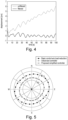
Fig. 4 is a graph of simulated data showing tower displacement plotted against time for an unfiltered signal χ (blue, upper line) and a filtered signal χ f1 (red, lower line). The unfiltered signal contains wave frequency excitation as well as static and quasi-static wind frequency excitation. The filtered signal is based on equation (5) above with
- As can be seen, the filtered signal shows an average displacement centred around zero whereas the unfiltered signal shows a displacement increasing with time.
- The
blade pitch controller 20 has a significantly simpler implementation compared to theprior art controller 10 ofFig. 2 , whilst providing very similar results. - The table below presents a lifetime comparison of a "Basic" controller (i.e. the nominal control system 11) with the
blade pitch controller 10 ofFig. 2 (labelled as "Advanced" in the table) and theblade pitch controller 20 of the present invention and shown inFig. 3 (labelled as "Simplified" in the table). Eleven different controller performance comparison parameters are compared.
- All performance comparison parameters show that the simplified controller (
blade pitch controller 20 of the present invention) yields similar performance as the advanced controller (prior artblade pitch controller 10 ofFig. 2 ). The results shaded in blue (the first five results columns) are desirable effects of tower feedback control. The results shaded in red (the sixth, seventh, and ninth result columns) are undesirable effects of tower feedback control. - The controller performance comparison parameters that are assessed are defined as follows:

-
Fig. 5 presents a lifetime comparison of the accumulation of fatigue damage in the wind turbine foundation with theblade pitch controller 20 of the present invention (labelled as "Proposed simplified controller) compared with the prior artblade pitch controller 10 ofFig. 2 (labelled as "Advanced controller") and the nominal control system 11 (labelled as "Basic control w/o [without] load reduction"). As can been seen, theblade pitch controller 20 of the present invention provides similar performance in terms of fatigue reduction as the prior artblade pitch controller 10 ofFig. 2 . - The results of a simulation illustrating the effectiveness of the
blade pitch controller 20 of the present invention compared to conventional damping control are presented inFigs. 6a-d . In these graphs, the black line represents theblade pitch controller 20 of the present invention (labelled as "Proposed damping + stiffness controller), the blue line represents a prior art conventional damping controller (labelled as "Conventional damping controller"), and the red line represents using just the nominal control system 11 (labelled as "Basic controller w/o [without] load reduction"). -
Fig. 6(a) is a plot of power density measured in m2/Hz as a function of frequency, showing power spectral density of the tower top displacement. -
Fig. 6(b) is a plot of power density measured in deg2/Hz as a function of frequency, showing power spectral density of the blades' pitch angle. -
Fig. 6(c) is a plot of tower top displacement as a function of time. -
Fig. 6(d) is a plot of the blades' collective pitch angle as a function of time. - From these plots, it can be seen that both tower motion and the blades' pitch activity are significantly increased in a frequency range around 0.1 Hz with the prior art conventional damping controller. However, the
blade pitch controller 20 of the present invention (proposed damping+stiffness controller) eliminates this undesirable behaviour. - The
blade pitch controller 20 of the present invention (proposed damping+stiffness controller) could also provide additional stiffness for excitation mechanisms other than waves, if their excitation frequency is above the selected high pass filter frequency and within the bandwidth of the blade pitch actuator (and outside the notch filter frequency area if this is applied). -
- 1. Van der Hooft E, Schaak P, Van Engelen T. Wind turbine control algorithms. DOWEC project-DOWEC-F1W1-EH-03-094/0, Task-3 report 2003. (Van der Hooft, 2003)
- 2. Bossanyi E. Wind turbine control for load reduction. Wind Energy 2003; 6(3):229-244. (Bossanyi, 2003)
- 3. Smilden E, Bachynski E E, Sørensen A J, Amdahl J. Wave disturbance rejection for monopile offshore wind turbines. Wind Energy 2018. https://doi.org/10.1002/we.2273 . (Smilden, 2018).
Claims (14)
- A blade pitch controller (20) for a fixed foundation offshore wind turbine (1), the blade pitch controller (20) comprising a nominal control system (11) and a tower feedback loop (22),wherein the tower feedback loop (22) comprises a filtering system (25) and a feedback controller (17');the nominal control system (11) is arranged to control a blade pitch of the wind turbine in order to optimise power production;the filtering system (25) comprises a high-pass filter with a filter frequency of less than 0.2 Hz, the filtering system (25) being arranged to receive at least one of position or velocity measurements or estimates of the wind turbine (1) as input and to output at least one filtered position or velocity measurements or estimates of the wind turbine (1); andthe feedback controller (17') is arranged to receive at least one of the output filtered position or velocity measurements or estimates of the wind turbine (1) from the filtering system (25) and to output a blade pitch reference signal determined from at least one of the filtered position or velocity measurements or estimates of the wind turbine (1) to the nominal control system (11), wherein the blade pitch reference signal is an adjustment which is added to a nominal blade pitch reference signal provided from a basic controller in the nominal control system (11), such that the tower feedback loop (22) is arranged to control wind turbine blade pitch so as to provide additional effective stiffness to the wind turbine (1) in response to motion of the wind turbine (1) above the filter frequency of the high-pass filter of the filtering system (25).
- A blade pitch controller (20) as claimed in claim 1, wherein the filtering system (25) comprises one or more of a low-pass filter and a notch filter.
- A blade pitch controller (20) as claimed in claim 1 or 2, wherein the tower feedback loop (22) is arranged to control wind turbine blade pitch so as to provide additional effective stiffness to the wind turbine (1) in response to:both wave- and wind-induced motion of the wind turbine (1); and/ormotion of the wind turbine (1) within a bandwidth of a blade pitch actuator.
- A blade pitch controller (20) as claimed in any preceding claim, wherein the position or velocity measurements or estimates provided as input to the filtering system (25) are provided from one or more sensors located on a tower (5) or foundation (6) of the wind turbine (1).
- A blade pitch controller (20) as claimed in claim 4, wherein the one or more sensors are located at or near a water line on the wind turbine (1).
- A blade pitch controller (20) as claimed in any preceding claim, wherein the filtering system (25) is arranged to filter position and velocity measurements and/or estimates of the wind turbine (1) differently.
- A blade pitch controller (20) as claimed in any preceding claim, wherein the filtering system (25) is arranged to filter out: static and/or quasi-static motion; and/or motion at a blade passing frequency.
- A method of controlling blade pitch of a fixed foundation offshore wind turbine (1), the method comprising using a blade pitch controller (20) as claimed in any preceding claim to control the blade pitch so as to provide additional the effective stiffness to the wind turbine (1) in response to motion of the wind turbine (1) above the filter frequency of the high-pass filter of the filtering system (25).
- A method as claimed in claim 8, the method comprising controlling wind turbine blade pitch so as to provide additional effective stiffness to the wind turbine (1) in response to both wave- and wind-induced motion of the wind turbine (1).
- A method as claimed in claim 8 or 9, the method comprising controlling wind turbine blade pitch so as to provide additional effective stiffness to the wind turbine (1) in response to motion of the wind turbine (1) within a bandwidth of a blade pitch actuator.
- A method as claimed in claim 8, 9 or 10, the method comprising:using the filtering system (25) to filter position and/or velocity measurements and/or estimates of the wind turbine (1); and/ordetermining a blade pitch reference signal from filtered position and/or velocity measurements and/or estimates of the wind turbine (1).
- A method as claimed in any of claims 8 to 11, the method comprising:filtering position and velocity measurements and/or estimates of the wind turbine (1) differently;filtering out static and/or quasi-static motion; and/orfiltering out motion at a blade passing frequency.
- A fixed foundation offshore wind turbine (1) comprising a blade pitch controller (20) as claimed in any of claims 1 to 7.
- A tower feedback controller (17') for a blade pitch controller (20) for a fixed foundation offshore wind turbine (1), wherein the tower feedback controller (17') comprises a filtering system (25) and the filtering system (25) comprises a high-pass filter with a filter frequency of less than 0.2Hz, the filtering system (25) being arranged to receive at least one position or velocity measurements or estimates of the wind turbine (1) as input and to output at least one filtered position or velocity measurements or estimates of the wind turbine (1), and the feedback controller (17') is arranged to receive the output at least one filtered position or velocity measurements or estimates of the wind turbine (1) from the filtering system (25) and to output a blade pitch reference signal determined from the filtered at least one position or velocity measurements or estimates of the wind turbine (1) to a nominal control system (11) arranged to control a blade pitch of the wind turbine (1) in order to optimise power production, wherein the blade pitch reference signal is an adjustment which is added to a nominal blade pitch reference signal provided from a basic controller in the nominal control system (11), such that the tower feedback controller is arranged to control wind turbine blade pitch so as to provide additional effective stiffness to the wind turbine (1) in response to motion of the wind turbine (1) above the filter frequency of the high-pass filter of the filtering system (25).
Priority Applications (1)
| Application Number | Priority Date | Filing Date | Title |
|---|---|---|---|
| EP25180028.0A EP4596872A3 (en) | 2019-12-13 | 2020-11-18 | Blade pitch controller for a wind turbine |
Applications Claiming Priority (2)
| Application Number | Priority Date | Filing Date | Title |
|---|---|---|---|
| GB1918423.3A GB2590388B (en) | 2019-12-13 | 2019-12-13 | Blade pitch controller for a wind turbine |
| PCT/NO2020/050284 WO2021118361A1 (en) | 2019-12-13 | 2020-11-18 | Blade pitch controller for a wind turbine |
Related Child Applications (2)
| Application Number | Title | Priority Date | Filing Date |
|---|---|---|---|
| EP25180028.0A Division EP4596872A3 (en) | 2019-12-13 | 2020-11-18 | Blade pitch controller for a wind turbine |
| EP25180028.0A Division-Into EP4596872A3 (en) | 2019-12-13 | 2020-11-18 | Blade pitch controller for a wind turbine |
Publications (4)
| Publication Number | Publication Date |
|---|---|
| EP4073375A1 EP4073375A1 (en) | 2022-10-19 |
| EP4073375A4 EP4073375A4 (en) | 2023-12-27 |
| EP4073375B1 true EP4073375B1 (en) | 2025-07-09 |
| EP4073375C0 EP4073375C0 (en) | 2025-07-09 |
Family
ID=69186806
Family Applications (2)
| Application Number | Title | Priority Date | Filing Date |
|---|---|---|---|
| EP20899949.0A Active EP4073375B1 (en) | 2019-12-13 | 2020-11-18 | Blade pitch controller for a wind turbine |
| EP25180028.0A Pending EP4596872A3 (en) | 2019-12-13 | 2020-11-18 | Blade pitch controller for a wind turbine |
Family Applications After (1)
| Application Number | Title | Priority Date | Filing Date |
|---|---|---|---|
| EP25180028.0A Pending EP4596872A3 (en) | 2019-12-13 | 2020-11-18 | Blade pitch controller for a wind turbine |
Country Status (9)
| Country | Link |
|---|---|
| US (1) | US11754045B2 (en) |
| EP (2) | EP4073375B1 (en) |
| JP (1) | JP7507241B2 (en) |
| KR (1) | KR102515403B1 (en) |
| AU (1) | AU2020402378B2 (en) |
| CA (1) | CA3164658C (en) |
| GB (1) | GB2590388B (en) |
| PL (1) | PL4073375T3 (en) |
| WO (1) | WO2021118361A1 (en) |
Families Citing this family (5)
| Publication number | Priority date | Publication date | Assignee | Title |
|---|---|---|---|---|
| US11306700B2 (en) * | 2019-10-25 | 2022-04-19 | Siemens Gamesa Renewable Energy A/S | Floating wind turbine blade pitch adjustment for wave activity |
| GB2590388B (en) | 2019-12-13 | 2022-02-16 | Equinor Energy As | Blade pitch controller for a wind turbine |
| EP4179197B1 (en) * | 2020-07-10 | 2025-05-14 | Vestas Wind Systems A/S | De-rating wind turbine tower lateral oscillation control |
| EP4001636A1 (en) * | 2020-11-19 | 2022-05-25 | Siemens Gamesa Renewable Energy A/S | Controlling an offshore wind turbine using active add-ons |
| JP2024077833A (en) * | 2022-11-29 | 2024-06-10 | 三菱重工業株式会社 | Anomaly diagnosis system and method for wind power generation equipment |
Family Cites Families (16)
| Publication number | Priority date | Publication date | Assignee | Title |
|---|---|---|---|---|
| JP2010514978A (en) * | 2006-12-28 | 2010-05-06 | クリッパー・ウィンドパワー・テクノロジー・インコーポレーテッド | Damping tower resonant motion and symmetric blade motion using estimation methods in wind turbines |
| GB2466649B (en) * | 2008-12-30 | 2014-01-29 | Hywind As | Blade pitch control in a wind turbine installation |
| US8169098B2 (en) * | 2010-12-22 | 2012-05-01 | General Electric Company | Wind turbine and operating same |
| JP5443629B1 (en) * | 2012-08-28 | 2014-03-19 | 三井造船株式会社 | Offshore wind turbine generator and wind turbine controller |
| ES2920684T3 (en) * | 2013-12-09 | 2022-08-08 | Gen Electric | System and method to reduce the oscillation loads of a wind turbine |
| US10415548B2 (en) * | 2014-07-09 | 2019-09-17 | Vestas Wind Systems A/S | Active promotion of wind turbine tower oscillations |
| JP6506664B2 (en) * | 2015-09-10 | 2019-04-24 | 株式会社日立製作所 | Wind power generation system or control method of wind power generation system |
| EP3478960B1 (en) * | 2016-06-30 | 2022-08-03 | Vestas Wind Systems A/S | Diagnostic system, wind turbine system, method for use in a wind turbine and computer program product |
| DE102016212362A1 (en) * | 2016-07-06 | 2018-01-11 | Universität Stuttgart | Lidar-based multivariable feedforward control of wind turbines |
| EP3500751B1 (en) * | 2016-08-17 | 2021-03-24 | Vestas Wind Systems A/S | Dynamic controlled wind turbine shutdown |
| KR20240025054A (en) * | 2016-11-29 | 2024-02-26 | 하이윈드 에이에스 | Control system for a floating wind turbine structure |
| EP3580452B1 (en) * | 2017-02-10 | 2023-07-19 | Vestas Wind Systems A/S | Position based vibration reduction of nacelle movement |
| DK201770358A1 (en) * | 2017-05-19 | 2018-11-23 | Vestas Wind Systems A/S | Position based vibration reduction of nacelle movement |
| JP2019094886A (en) * | 2017-11-28 | 2019-06-20 | 株式会社日立製作所 | Floating type offshore wind power generation device |
| ES2953633T3 (en) * | 2018-05-09 | 2023-11-14 | Vestas Wind Sys As | Rotor control system to reduce structural vibrations of a wind turbine |
| GB2590388B (en) | 2019-12-13 | 2022-02-16 | Equinor Energy As | Blade pitch controller for a wind turbine |
-
2019
- 2019-12-13 GB GB1918423.3A patent/GB2590388B/en active Active
-
2020
- 2020-11-18 CA CA3164658A patent/CA3164658C/en active Active
- 2020-11-18 US US17/756,973 patent/US11754045B2/en active Active
- 2020-11-18 JP JP2022535522A patent/JP7507241B2/en active Active
- 2020-11-18 WO PCT/NO2020/050284 patent/WO2021118361A1/en not_active Ceased
- 2020-11-18 AU AU2020402378A patent/AU2020402378B2/en active Active
- 2020-11-18 KR KR1020227021901A patent/KR102515403B1/en active Active
- 2020-11-18 EP EP20899949.0A patent/EP4073375B1/en active Active
- 2020-11-18 PL PL20899949.0T patent/PL4073375T3/en unknown
- 2020-11-18 EP EP25180028.0A patent/EP4596872A3/en active Pending
Also Published As
| Publication number | Publication date |
|---|---|
| GB201918423D0 (en) | 2020-01-29 |
| US20230025543A1 (en) | 2023-01-26 |
| CA3164658A1 (en) | 2021-06-17 |
| BR112022011501A2 (en) | 2022-08-23 |
| EP4073375A4 (en) | 2023-12-27 |
| JP7507241B2 (en) | 2024-06-27 |
| GB2590388B (en) | 2022-02-16 |
| KR102515403B1 (en) | 2023-03-29 |
| PL4073375T3 (en) | 2025-11-12 |
| EP4596872A3 (en) | 2025-10-22 |
| JP2023502540A (en) | 2023-01-24 |
| GB2590388A (en) | 2021-06-30 |
| AU2020402378B2 (en) | 2022-09-22 |
| KR20220127813A (en) | 2022-09-20 |
| WO2021118361A1 (en) | 2021-06-17 |
| AU2020402378A1 (en) | 2022-07-07 |
| CA3164658C (en) | 2024-10-22 |
| EP4073375A1 (en) | 2022-10-19 |
| EP4073375C0 (en) | 2025-07-09 |
| US11754045B2 (en) | 2023-09-12 |
| EP4596872A2 (en) | 2025-08-06 |
Similar Documents
| Publication | Publication Date | Title |
|---|---|---|
| US11754045B2 (en) | Blade pitch controller for a wind turbine | |
| KR101660553B1 (en) | Blade pitch control in a wind turbine installation | |
| CN110446853B (en) | System and method for managing torsional oscillations of a wind turbine tower | |
| US8026623B2 (en) | Wind turbine generator, active damping method thereof, and windmill tower | |
| CN114258459B (en) | Using blade load signals to reduce edgewise vibration | |
| EP3080444B1 (en) | System and method for reducing oscillation loads of wind turbine | |
| US8803351B2 (en) | Control method for a wind turbine | |
| EP2489872A1 (en) | Blade load reduction for wind turbine | |
| CN111512043B (en) | Method and system for controlling wind turbines to manage edge blade vibration | |
| JP7440636B2 (en) | wind turbine control | |
| CN118765348A (en) | Torque limiter based on current torque value | |
| BR112022011501B1 (en) | BLADE PITCH CONTROLLER FOR A WIND TURBINE |
Legal Events
| Date | Code | Title | Description |
|---|---|---|---|
| STAA | Information on the status of an ep patent application or granted ep patent |
Free format text: STATUS: THE INTERNATIONAL PUBLICATION HAS BEEN MADE |
|
| PUAI | Public reference made under article 153(3) epc to a published international application that has entered the european phase |
Free format text: ORIGINAL CODE: 0009012 |
|
| STAA | Information on the status of an ep patent application or granted ep patent |
Free format text: STATUS: REQUEST FOR EXAMINATION WAS MADE |
|
| 17P | Request for examination filed |
Effective date: 20220713 |
|
| AK | Designated contracting states |
Kind code of ref document: A1 Designated state(s): AL AT BE BG CH CY CZ DE DK EE ES FI FR GB GR HR HU IE IS IT LI LT LU LV MC MK MT NL NO PL PT RO RS SE SI SK SM TR |
|
| DAV | Request for validation of the european patent (deleted) | ||
| DAX | Request for extension of the european patent (deleted) | ||
| A4 | Supplementary search report drawn up and despatched |
Effective date: 20231127 |
|
| RIC1 | Information provided on ipc code assigned before grant |
Ipc: F03D 9/25 20160101ALI20231121BHEP Ipc: F03D 7/02 20060101ALI20231121BHEP Ipc: F03D 7/04 20060101AFI20231121BHEP |
|
| STAA | Information on the status of an ep patent application or granted ep patent |
Free format text: STATUS: EXAMINATION IS IN PROGRESS |
|
| 17Q | First examination report despatched |
Effective date: 20240829 |
|
| GRAP | Despatch of communication of intention to grant a patent |
Free format text: ORIGINAL CODE: EPIDOSNIGR1 |
|
| STAA | Information on the status of an ep patent application or granted ep patent |
Free format text: STATUS: GRANT OF PATENT IS INTENDED |
|
| INTG | Intention to grant announced |
Effective date: 20250304 |
|
| GRAS | Grant fee paid |
Free format text: ORIGINAL CODE: EPIDOSNIGR3 |
|
| GRAA | (expected) grant |
Free format text: ORIGINAL CODE: 0009210 |
|
| STAA | Information on the status of an ep patent application or granted ep patent |
Free format text: STATUS: THE PATENT HAS BEEN GRANTED |
|
| AK | Designated contracting states |
Kind code of ref document: B1 Designated state(s): AL AT BE BG CH CY CZ DE DK EE ES FI FR GB GR HR HU IE IS IT LI LT LU LV MC MK MT NL NO PL PT RO RS SE SI SK SM TR |
|
| REG | Reference to a national code |
Ref country code: GB Ref legal event code: FG4D |
|
| REG | Reference to a national code |
Ref country code: CH Ref legal event code: EP |
|
| REG | Reference to a national code |
Ref country code: IE Ref legal event code: FG4D |
|
| REG | Reference to a national code |
Ref country code: DE Ref legal event code: R096 Ref document number: 602020054390 Country of ref document: DE |
|
| U01 | Request for unitary effect filed |
Effective date: 20250808 |
|
| U07 | Unitary effect registered |
Designated state(s): AT BE BG DE DK EE FI FR IT LT LU LV MT NL PT RO SE SI Effective date: 20250916 |
|
| PG25 | Lapsed in a contracting state [announced via postgrant information from national office to epo] |
Ref country code: IS Free format text: LAPSE BECAUSE OF FAILURE TO SUBMIT A TRANSLATION OF THE DESCRIPTION OR TO PAY THE FEE WITHIN THE PRESCRIBED TIME-LIMIT Effective date: 20251109 |
|
| PGFP | Annual fee paid to national office [announced via postgrant information from national office to epo] |
Ref country code: NO Payment date: 20251120 Year of fee payment: 6 |
|
| PG25 | Lapsed in a contracting state [announced via postgrant information from national office to epo] |
Ref country code: HR Free format text: LAPSE BECAUSE OF FAILURE TO SUBMIT A TRANSLATION OF THE DESCRIPTION OR TO PAY THE FEE WITHIN THE PRESCRIBED TIME-LIMIT Effective date: 20250709 |
|
| PG25 | Lapsed in a contracting state [announced via postgrant information from national office to epo] |
Ref country code: GR Free format text: LAPSE BECAUSE OF FAILURE TO SUBMIT A TRANSLATION OF THE DESCRIPTION OR TO PAY THE FEE WITHIN THE PRESCRIBED TIME-LIMIT Effective date: 20251010 |
|
| U20 | Renewal fee for the european patent with unitary effect paid |
Year of fee payment: 6 Effective date: 20251212 |
|
| PG25 | Lapsed in a contracting state [announced via postgrant information from national office to epo] |
Ref country code: RS Free format text: LAPSE BECAUSE OF FAILURE TO SUBMIT A TRANSLATION OF THE DESCRIPTION OR TO PAY THE FEE WITHIN THE PRESCRIBED TIME-LIMIT Effective date: 20251009 |
|
| PG25 | Lapsed in a contracting state [announced via postgrant information from national office to epo] |
Ref country code: ES Free format text: LAPSE BECAUSE OF FAILURE TO SUBMIT A TRANSLATION OF THE DESCRIPTION OR TO PAY THE FEE WITHIN THE PRESCRIBED TIME-LIMIT Effective date: 20250709 |
|
| PG25 | Lapsed in a contracting state [announced via postgrant information from national office to epo] |
Ref country code: SM Free format text: LAPSE BECAUSE OF FAILURE TO SUBMIT A TRANSLATION OF THE DESCRIPTION OR TO PAY THE FEE WITHIN THE PRESCRIBED TIME-LIMIT Effective date: 20250709 |
|
| PG25 | Lapsed in a contracting state [announced via postgrant information from national office to epo] |
Ref country code: CZ Free format text: LAPSE BECAUSE OF FAILURE TO SUBMIT A TRANSLATION OF THE DESCRIPTION OR TO PAY THE FEE WITHIN THE PRESCRIBED TIME-LIMIT Effective date: 20250709 |
|
| PGFP | Annual fee paid to national office [announced via postgrant information from national office to epo] |
Ref country code: PL Payment date: 20251110 Year of fee payment: 6 |
|
| PG25 | Lapsed in a contracting state [announced via postgrant information from national office to epo] |
Ref country code: SK Free format text: LAPSE BECAUSE OF FAILURE TO SUBMIT A TRANSLATION OF THE DESCRIPTION OR TO PAY THE FEE WITHIN THE PRESCRIBED TIME-LIMIT Effective date: 20250709 |
|
| PLBE | No opposition filed within time limit |
Free format text: ORIGINAL CODE: 0009261 |
|
| STAA | Information on the status of an ep patent application or granted ep patent |
Free format text: STATUS: NO OPPOSITION FILED WITHIN TIME LIMIT |