EP3500751B1 - Dynamic controlled wind turbine shutdown - Google Patents
Dynamic controlled wind turbine shutdown Download PDFInfo
- Publication number
- EP3500751B1 EP3500751B1 EP17754254.5A EP17754254A EP3500751B1 EP 3500751 B1 EP3500751 B1 EP 3500751B1 EP 17754254 A EP17754254 A EP 17754254A EP 3500751 B1 EP3500751 B1 EP 3500751B1
- Authority
- EP
- European Patent Office
- Prior art keywords
- wind turbine
- rotor
- rotor speed
- pitch
- controller
- Prior art date
- Legal status (The legal status is an assumption and is not a legal conclusion. Google has not performed a legal analysis and makes no representation as to the accuracy of the status listed.)
- Active
Links
- 238000000034 method Methods 0.000 claims description 60
- 230000001133 acceleration Effects 0.000 claims description 42
- 230000008859 change Effects 0.000 claims description 29
- 230000009467 reduction Effects 0.000 claims description 25
- 230000000750 progressive effect Effects 0.000 claims description 12
- 230000004044 response Effects 0.000 claims description 3
- 238000004590 computer program Methods 0.000 claims description 2
- 230000004048 modification Effects 0.000 description 8
- 238000012986 modification Methods 0.000 description 8
- 238000013461 design Methods 0.000 description 7
- 230000008569 process Effects 0.000 description 5
- 230000010355 oscillation Effects 0.000 description 4
- 230000010354 integration Effects 0.000 description 2
- 238000005259 measurement Methods 0.000 description 2
- 230000003068 static effect Effects 0.000 description 2
- 235000009413 Ratibida columnifera Nutrition 0.000 description 1
- 241000510442 Ratibida peduncularis Species 0.000 description 1
- 230000009471 action Effects 0.000 description 1
- 230000006978 adaptation Effects 0.000 description 1
- 230000003044 adaptive effect Effects 0.000 description 1
- 230000002411 adverse Effects 0.000 description 1
- 238000013459 approach Methods 0.000 description 1
- 238000005452 bending Methods 0.000 description 1
- 230000009286 beneficial effect Effects 0.000 description 1
- 238000004891 communication Methods 0.000 description 1
- 238000011217 control strategy Methods 0.000 description 1
- 238000013016 damping Methods 0.000 description 1
- 230000003247 decreasing effect Effects 0.000 description 1
- 230000001419 dependent effect Effects 0.000 description 1
- 230000004069 differentiation Effects 0.000 description 1
- 230000007613 environmental effect Effects 0.000 description 1
- 238000011156 evaluation Methods 0.000 description 1
- 230000002349 favourable effect Effects 0.000 description 1
- 238000007667 floating Methods 0.000 description 1
- 238000012545 processing Methods 0.000 description 1
- 230000002459 sustained effect Effects 0.000 description 1
- 230000007704 transition Effects 0.000 description 1
Images


Classifications
-
- F—MECHANICAL ENGINEERING; LIGHTING; HEATING; WEAPONS; BLASTING
- F03—MACHINES OR ENGINES FOR LIQUIDS; WIND, SPRING, OR WEIGHT MOTORS; PRODUCING MECHANICAL POWER OR A REACTIVE PROPULSIVE THRUST, NOT OTHERWISE PROVIDED FOR
- F03D—WIND MOTORS
- F03D7/00—Controlling wind motors
- F03D7/02—Controlling wind motors the wind motors having rotation axis substantially parallel to the air flow entering the rotor
- F03D7/0264—Controlling wind motors the wind motors having rotation axis substantially parallel to the air flow entering the rotor for stopping; controlling in emergency situations
-
- F—MECHANICAL ENGINEERING; LIGHTING; HEATING; WEAPONS; BLASTING
- F03—MACHINES OR ENGINES FOR LIQUIDS; WIND, SPRING, OR WEIGHT MOTORS; PRODUCING MECHANICAL POWER OR A REACTIVE PROPULSIVE THRUST, NOT OTHERWISE PROVIDED FOR
- F03D—WIND MOTORS
- F03D7/00—Controlling wind motors
- F03D7/02—Controlling wind motors the wind motors having rotation axis substantially parallel to the air flow entering the rotor
- F03D7/022—Adjusting aerodynamic properties of the blades
- F03D7/0224—Adjusting blade pitch
-
- F—MECHANICAL ENGINEERING; LIGHTING; HEATING; WEAPONS; BLASTING
- F03—MACHINES OR ENGINES FOR LIQUIDS; WIND, SPRING, OR WEIGHT MOTORS; PRODUCING MECHANICAL POWER OR A REACTIVE PROPULSIVE THRUST, NOT OTHERWISE PROVIDED FOR
- F03D—WIND MOTORS
- F03D7/00—Controlling wind motors
- F03D7/02—Controlling wind motors the wind motors having rotation axis substantially parallel to the air flow entering the rotor
- F03D7/0276—Controlling wind motors the wind motors having rotation axis substantially parallel to the air flow entering the rotor controlling rotor speed, e.g. variable speed
-
- F—MECHANICAL ENGINEERING; LIGHTING; HEATING; WEAPONS; BLASTING
- F03—MACHINES OR ENGINES FOR LIQUIDS; WIND, SPRING, OR WEIGHT MOTORS; PRODUCING MECHANICAL POWER OR A REACTIVE PROPULSIVE THRUST, NOT OTHERWISE PROVIDED FOR
- F03D—WIND MOTORS
- F03D7/00—Controlling wind motors
- F03D7/02—Controlling wind motors the wind motors having rotation axis substantially parallel to the air flow entering the rotor
- F03D7/0296—Controlling wind motors the wind motors having rotation axis substantially parallel to the air flow entering the rotor to prevent, counteract or reduce noise emissions
-
- F—MECHANICAL ENGINEERING; LIGHTING; HEATING; WEAPONS; BLASTING
- F03—MACHINES OR ENGINES FOR LIQUIDS; WIND, SPRING, OR WEIGHT MOTORS; PRODUCING MECHANICAL POWER OR A REACTIVE PROPULSIVE THRUST, NOT OTHERWISE PROVIDED FOR
- F03D—WIND MOTORS
- F03D7/00—Controlling wind motors
- F03D7/02—Controlling wind motors the wind motors having rotation axis substantially parallel to the air flow entering the rotor
- F03D7/04—Automatic control; Regulation
- F03D7/042—Automatic control; Regulation by means of an electrical or electronic controller
- F03D7/043—Automatic control; Regulation by means of an electrical or electronic controller characterised by the type of control logic
-
- F—MECHANICAL ENGINEERING; LIGHTING; HEATING; WEAPONS; BLASTING
- F05—INDEXING SCHEMES RELATING TO ENGINES OR PUMPS IN VARIOUS SUBCLASSES OF CLASSES F01-F04
- F05B—INDEXING SCHEME RELATING TO WIND, SPRING, WEIGHT, INERTIA OR LIKE MOTORS, TO MACHINES OR ENGINES FOR LIQUIDS COVERED BY SUBCLASSES F03B, F03D AND F03G
- F05B2270/00—Control
- F05B2270/30—Control parameters, e.g. input parameters
- F05B2270/309—Rate of change of parameters
-
- F—MECHANICAL ENGINEERING; LIGHTING; HEATING; WEAPONS; BLASTING
- F05—INDEXING SCHEMES RELATING TO ENGINES OR PUMPS IN VARIOUS SUBCLASSES OF CLASSES F01-F04
- F05B—INDEXING SCHEME RELATING TO WIND, SPRING, WEIGHT, INERTIA OR LIKE MOTORS, TO MACHINES OR ENGINES FOR LIQUIDS COVERED BY SUBCLASSES F03B, F03D AND F03G
- F05B2270/00—Control
- F05B2270/30—Control parameters, e.g. input parameters
- F05B2270/327—Rotor or generator speeds
-
- F—MECHANICAL ENGINEERING; LIGHTING; HEATING; WEAPONS; BLASTING
- F05—INDEXING SCHEMES RELATING TO ENGINES OR PUMPS IN VARIOUS SUBCLASSES OF CLASSES F01-F04
- F05B—INDEXING SCHEME RELATING TO WIND, SPRING, WEIGHT, INERTIA OR LIKE MOTORS, TO MACHINES OR ENGINES FOR LIQUIDS COVERED BY SUBCLASSES F03B, F03D AND F03G
- F05B2270/00—Control
- F05B2270/30—Control parameters, e.g. input parameters
- F05B2270/334—Vibration measurements
-
- Y—GENERAL TAGGING OF NEW TECHNOLOGICAL DEVELOPMENTS; GENERAL TAGGING OF CROSS-SECTIONAL TECHNOLOGIES SPANNING OVER SEVERAL SECTIONS OF THE IPC; TECHNICAL SUBJECTS COVERED BY FORMER USPC CROSS-REFERENCE ART COLLECTIONS [XRACs] AND DIGESTS
- Y02—TECHNOLOGIES OR APPLICATIONS FOR MITIGATION OR ADAPTATION AGAINST CLIMATE CHANGE
- Y02E—REDUCTION OF GREENHOUSE GAS [GHG] EMISSIONS, RELATED TO ENERGY GENERATION, TRANSMISSION OR DISTRIBUTION
- Y02E10/00—Energy generation through renewable energy sources
- Y02E10/70—Wind energy
- Y02E10/72—Wind turbines with rotation axis in wind direction
Definitions
- Embodiments of the present invention relate to methods and control systems for controlling the shutdown of a wind turbine, in particular to controlling the wind turbine shutdown in a dynamic and adaptive manner.
- Figure 1 illustrates a large wind turbine 1, comprising a tower 10, a wind turbine nacelle 20 positioned on top of the tower 10 and a rotor.
- the illustrated wind turbine rotor comprises three wind turbine blades 32 and a hub 34.
- the hub 34 is located at a height H above the base of the tower and each of the three wind turbine blades 32 are mounted to the hub. Whilst the wind turbine rotor is shown as having three wind turbine blades, the wind turbine rotor could comprise a different number of blades 32.
- the blades 32 each have a length L.
- the hub 34 is typically connected to the nacelle 20 through a low speed shaft (not shown) extending from the front of the nacelle 20.
- the low speed shaft drives a gearbox (also not shown) which steps up the rotational speed and, in turn, drives an electrical generator within the nacelle 20 for converting the energy extracted from the wind by the rotating blades 32 into electrical power output.
- the wind turbine rotor may be directly coupled to the electrical generator, i.e. direct-drive turbines.
- the wind turbine blades 32 define a swept area A, which is the area of a circle delineated by the rotating blades 32.
- the swept area dictates how much of a given air mass is intercepted by the wind turbine 1 and, thus, influences the power output of the wind turbine 1 and the forces and bending moments experienced by the components of the turbine 1 during operation.
- the turbine may stand onshore, as illustrated, or offshore. In the latter case the tower will be connected to a monopile, tripod, lattice or other foundation structure, and the foundation could be either fixed or floating.
- Each wind turbine has a wind turbine controller that processes inputs from sensors and other control systems and generates output signals for actuators such as blade pitch actuators, generator torque controller, generator contactors, and yaw motors etc.
- actuators such as blade pitch actuators, generator torque controller, generator contactors, and yaw motors etc.
- the output signals generated by the wind turbine controller regulate the operation of the wind turbine 1.
- the wind turbine controller may generate output signals that cause the speed of the wind turbine rotor to decrease to zero. For example, the wind turbine controller may cause the blade pitch angle to be increased (towards 90 degrees) using the blade pitch actuators. This is commonly known as pitching the blade out, which causes the power output to be reduced since the pitched blade acts as an aerodynamic brake.
- a shutdown procedure may be initiated to change the wind turbine 1 from an operational state to a static state, where the wind turbine rotor is stationary.
- the shutdown procedure may be initiated in order to avoid excessive loads on the components of the wind turbine 1, for example during extreme wind conditions and/or if the electric generator of the wind turbine 1 has been disconnected from the power grid.
- the combination of these two events is typically the worst case scenario for the loading of a wind turbine during a shutdown procedure.
- US2015/377215 discloses a method and a system for managing loads on a wind turbine.
- the method includes receiving a signal relative to a yaw misalignment of the wind turbine, generating a yaw error signal based on the yaw misalignment, and comparing the yaw error signal to a first predetermined yaw error threshold value.
- the method further includes shutting down the wind turbine if the yaw error signal remains greater than the second predetermined yaw error threshold value beyond the predetermined period of time.
- Embodiments of the invention relate generally to methods for controlling the operating parameters of a wind turbine during shutdown, controllers for implementing such methods and wind turbines including one or more of these controllers.
- certain loads experienced during the shutdown of a wind turbine can be reduced by providing improved control of the pitching of the blades of a wind turbine. This may reduce the required strength of the turbine elements or components, or alternatively may increase the expected lifetime of the relevant components.
- a method of controlling shutdown of a wind turbine having a rotor, the rotor comprising one or more wind turbine blades comprising: dynamically determining a rotor speed reference; obtaining a measure of the rotor speed of the rotor; obtaining a measure of a fore-aft movement of the wind turbine tower; determining an error between the rotor speed reference and the rotor speed of the rotor; and controlling a pitch of one or more of the wind turbine blades based on the determined error and the measured fore-aft movement of the wind turbine tower.
- rotor loading can be reduced quickly and efficiently in view of the current conditions that the wind turbine is subject to; in an embodiment this may be obtained by closed feedback loop control. This in turn reduces the extreme loading that the wind turbine would be expected to experience during the controlled shutdown, which may be taken into account when considering the design loads at the design stage of producing the wind turbine, and improve the safety of the wind turbine, in particular with reference to the stresses on the drivetrain and gearbox components.
- the method comprises obtaining a measure of a fore-aft movement of the wind turbine tower, and controlling the pitch of one or more of the wind turbine blades in further dependence on the measured fore-aft movement of the wind turbine tower.
- the turbine is prone to fore-aft movement, and by taking this movement into account during the shutdown the loading that the wind turbine tower experiences due to the fore-aft movement is directly taken into account, and thereby ensuring quickly and efficiently shutdown and at the same time keeping the loads of the tower structure and/or tower foundation down.
- the method further comprises determining whether the rotor speed of the rotor is increasing, wherein the dynamic determination of the rotor speed reference comprises maintaining a constant rotor speed reference value when the rotor speed of the rotor is determined to be increasing. This improves the control of the pitch actuation when the error between the rotor speed reference and the measured rotor speed of the rotor is large by controlling the rotor speed reference to reduce the time taken for the method to regain control of the speed of the rotor. In this manner, the rotor speed reference may be dynamically determined because it is determined at least in part based on an evaluation of the rotor speed of the rotor.
- the dynamic determination of the rotor speed reference may comprise setting the rotor speed reference value to be equal to the rotor speed of the rotor when the rotor speed of the rotor is determined to be less than the rotor speed reference. This acts to stop the method from attempting to increase the rotor speed of the rotor where the wind turbine blades are naturally slowing down more quickly than the dynamically determined reduction of the rotor speed reference value.
- the dynamic determination of the rotor speed reference may comprise progressively ramping the rotor speed reference down to zero when the rotor speed of the rotor is determined to be both higher than the rotor speed reference and to not be increasing. This advantageously reduces the speed of the rotor to zero when the error between the rotor speed reference and the measured rotor speed is not too large and thus when the method has control of the speed of the rotor.
- a rate of change of the wind turbine blade pitch may be reduced whilst the wind turbine tower is determined to be moving into the wind due to the fore-aft movement and/or wherein the rate of change of the wind turbine blade pitch is increased whilst the wind turbine tower is determined to be moving in the direction of the wind due to the fore-aft movement.
- the wind loading on the wind turbine blades may be maintained whilst the tower is moving forwards by either not pitching the wind turbine blade out any further, or by reducing the speed at which the wind turbine blade is pitched out.
- This change in the pitching out of the wind turbine blade will provide a comparatively large wind loading and wind resistance on the wind turbine blades that will act to counter the motion of the wind turbine into the wind.
- the wind loading on the wind turbine blades may be reduced whilst the tower is moving backwards, i.e. in the wind direction, by increasing the speed at which the wind turbine blades are pitched out and moved towards the feathered position. This will reduce the wind loading that would otherwise contribute to the speed of the aft movement of the wind turbine tower and thus would increase or sustain the tower oscillations in the plane parallel to the wind direction.
- the dynamic determining of the rotor speed reference may further comprise modifying the rotor speed reference based on the measured fore-aft movement of the wind turbine tower.
- the contribution to the control of the wind turbine blade pitching in view of the fore-aft movement of the wind turbine tower may be included in the control method by simply modifying the dynamically determined rotor speed reference.
- the method may further comprise determining an acceleration of the rotor based on the rotor speed of the rotor; wherein a rate of change of the wind turbine blade pitch is increased proportional to the acceleration when the acceleration is above a given threshold. Accordingly, the level of wear and fatigue experienced by the drivetrain and gearbox components during shutdown of the wind turbine may be limited.
- a gain reduction may be applied to a rate of change of the wind turbine blade pitch as a function of the pitch of the one or more wind turbine blades.
- an operating point may be defined by one or more measured quantities, for example the average wind speed, rotor speed, pitch angle or electrical power of the wind turbine.
- the gain reduction may be a progressive gain reduction and a rate of the progressive gain reduction may be based on one or more threshold angles of the pitch of one or more of the wind turbine blades so that the rate of pitch change may be altered as the blade moves towards the feathered position.
- the method may apply no gain reduction if the pitch is below a first threshold angle, a first rate of progressive gain reduction may be applied if the pitch is between the first threshold angle and a second threshold angle and a second rate of progressive gain reduction may be applied if the pitch is above the second threshold angle; wherein the first rate of progressive gain reduction is higher than the second rate of progressive gain reduction.
- the rate of the blade pitch change may be reduced as the blade moves towards the feathered position, with the loads on the system being minimised throughout the shutdown process.
- the pitch of each of the one or more wind turbine blades may be controlled individually. This enables rotor blade loads to be compensated for where there may be uneven loading on the rotor, for example the tilt and yaw moments at the main bearing of the wind turbine nacelle. This active control during wind turbine shutdown acts to prevent structural failure of the main components due to extreme loads and would also enable shutdown of the wind turbine when the blades are pitched at different positions.
- a controller will enable the blade pitch to be controlled based on a closed feedback loop control with a reference rotor speed that is dynamically determined so that rotor loading can be reduced quickly and efficiently in view of the current conditions that the wind turbine is subject to.
- This controller will act to reduce the extreme loading that the wind turbine may be expected to experience during the controlled shutdown. This can then be taken into account when considering the design loads at the design stage of producing the wind turbine and can improve the safety of the wind turbine.
- the controller may be configured to cause any of the above methods to be implemented in response to the controller receiving an emergency shutdown request.
- the emergency shutdown request may indicate, for example, that a failure has been detected in the controller and accordingly the shutdown methods may be tuned for the loads that would be expected to be experienced during such an emergency shutdown operation.
- a wind turbine comprising a rotor and one or more controllers according to the second aspect of the invention, wherein the rotor comprises one or more wind turbine blades.
- the controller may be included in a wind turbine. Where a single wind turbine comprises a plurality of controllers, the controllers may provide redundancy in the operation and control of the wind turbine during shutdown, for example in the event that one of the controllers fails.
- a wind turbine according to the third aspect of the invention may comprise one or more controllers each configured to control the pitch of a respective wind turbine blade of the one or more of the wind turbine blades.
- each controller may provide pitch control for a different blade so that the pitching of the wind turbine blades may be controlled individually and independently. This enables rotor blade fatigue loads to be compensated for where there may be uneven loading on the rotor, for example the tilt and yaw moments at the main bearing of the wind turbine nacelle.
- a corresponding computer program that when executed on a wind turbine controller causes the wind turbine controller to carry out any of the methods described herein.
- the process of shutting down a wind turbine 1 will not always take place in steady wind conditions and accordingly the method of the control system is preferably able to safely shut the wind turbine down in less favourable conditions, and even extreme conditions.
- the method of controlling the shutdown of the wind turbine 1 be able to quickly and safely stop the rotation of the wind turbine rotor, even in gusty conditions.
- gusty conditions is commonly known as a Mexican hat wind gust for its similarity to the cross-section of a sombrero.
- the steady wind speed drops briefly to a low, then quickly accelerates to a peak level before dropping again to a low and then recovering to the steady wind speed.
- the electric generator of the wind turbine 1 may be disconnected from the power grid if there is an electrical failure or simply a lack of demand; however, this disconnection removes the counter torque of the electric generator from the wind turbine rotor. This reduces the resistance to the rotation of the rotor and thus allows the speed of the rotor to increase further.
- FIG. 2 illustrates a control system that may be implemented in a wind turbine controller for controlling the shutdown of a wind turbine according to a general embodiment of the invention.
- the wind turbine controller 40 comprises a rotor speed reference unit 42, an error value controller 44 and a speed controller 46.
- the wind turbine controller 40 is preferably local to the wind turbine 1, for example in the tower 10 or in the nacelle 20, this reduces the possibility of communication issues preventing the controller from being able to cause the wind turbine 1 to perform a controlled shutdown. However, it will be appreciated that the wind turbine controller 40 may be located elsewhere.
- the rotor speed reference unit 42 When the controller 40 receives a signal instructing the controller to initiate a shutdown procedure, the rotor speed reference unit 42 will generate an initial rotor speed reference value.
- the rotor speed reference unit 42 receives a measure of the rotor speed of the wind turbine rotor and uses this measure as an input for dynamically determining a rotor speed reference value. It will be appreciated that the measure of the rotor speed may be obtained by integration of the output of a sensor that measures the acceleration of the rotor.
- the initial rotor speed reference value may be set to be equal to the measured rotor speed of the wind turbine rotor, to a filtered version of the measured rotor speed of the wind turbine rotor, or alternatively it may be set to the value of a target rotor speed that was in operation immediately prior to the controller 40 receiving a shutdown instruction.
- This rotor speed reference value is then communicated to the error value controller 44, which also receives the measure of the rotor speed of the wind turbine rotor.
- the error value controller 44 compares these two inputs to calculate an error between the rotor speed reference and the rotor speed of the wind turbine rotor.
- the error value controller 44 is preferably a proportional integral derivative (PID) controller, whereby the proportional term accounts for the current error value, the integral term accounts for the previous error values and the derivative term looks forward to possible future values.
- PID proportional integral derivative
- parameters of the PID controller may optionally be set such that the one or two of the proportional, integral or derivative terms are set to zero.
- the determined error is then communicated to the speed controller 46, which produces a pitch control signal for controlling the pitch of the wind turbine blades 32 based on the determined error. If the initial rotor speed reference value is set to be equal to the measured rotor speed of the wind turbine rotor at the first instance then there will initially be no determined error and accordingly the speed controller 46 will not initially cause the pitch of the wind turbine blades 32 to change.
- the rotor speed reference unit 42 will then continuously generate new rotor speed reference values for use in the controller 40 to produce pitch control signals that quickly and safely transition the wind turbine 1 from an operational state to a shutdown state where the wind turbine rotor is static and the pitch angle of the wind turbine blades 32 has been increased to an angle of roughly 90 degrees, i.e. the feathered position.
- the rotor speed reference value is dynamically determined in the sense that it is determined based on measured parameters of the wind turbine (for example rotor speed) and/or measured parameters of the external conditions (for example wind speed). This enables the controller 40 to modify the wind turbine shutdown procedure in order to maintain control of the rotor speed and minimise the loads experienced by the wind turbine 1.
- the rotor speed reference unit 42 monitors the rotor speed input to determine if the speed of the rotor is increasing or not. If it is determined that the rotor speed is increasing, then the rotor speed reference unit 42 adapts the existing continuous generation of new rotor speed reference values to hold the rotor speed reference constant.
- the rotor speed reference value may be reduced by the continuous generation of new rotor speed reference values, for example the rotor speed reference may be progressively ramped from the previous value to zero in a linear or non-linear manner.
- dynamically determining the rotor speed reference value comprises causing the rotor speed reference unit 42 to set the rotor speed reference value to be equal to the measured rotor speed of the wind turbine rotor 32 when it is determined that the measured rotor speed of the rotor is determined to be less than the rotor speed reference value.
- the controller 40 acts to prevent the determined error from causing the speed controller 46 to pitch the blades back into the wind and attempting to speed the rotor 32 up. The controller 40 will then continue to continuously generate new rotor speed reference values in the previous manner.
- Each of the above control strategies contribute to reduce the maximum rotor speed during shutdown, which in turn reduces the stress on drivetrain and gearbox components. This increases the safety of the wind turbine design and reduces the required design loads for designing the tower 10 and foundation of the wind turbine 1.
- the invention has been described using a single wind turbine controller 40 to control the collective pitch of each of the wind turbine blades 32 of the wind turbine 1.
- the wind turbine 1 is provided with a respective controller 40 for each of the wind turbine blades.
- the pitching of the three wind turbine blades 32 of a wind turbine may be individually controlled thus allowing rotor blade fatigue loads to be compensated for where there may be uneven loading on the rotor, for example the load due to the tilt and yaw moments at the main bearing of the wind turbine nacelle.
- the multiple controllers 40 may be used to provide redundancy in the control system, for example so that the remaining controllers 40 may take over in the event that one of the controllers is damaged by a lightning strike or another fault.
- FIG. 3 illustrates further elements of a control system that may be implemented in a wind turbine controller for controlling the shutdown of a wind turbine according to an embodiment of the invention.
- the wind turbine controller 50 explicitly illustrates a fore-aft tower damper 54, and also comprises a rotor speed reference unit 42, an error value controller 44 and a speed controller 46, with like reference numbers being used for like components with respect to the wind turbine controller 40. Accordingly, whilst the above description of wind turbine controller 40 will not be repeated herein, it applies equally to the corresponding components of wind turbine controller 50.
- Wind turbine controller 50 further comprises a low pass filter unit 52, a fore-aft tower damper 54, a time derivative unit 56, an acceleration limiter 58, and a gain scheduler 60. It will be appreciated from the below that each of these units may be used individually, and accordingly the wind turbine controller 40 may be modified to include one or more of these additional components without including the remaining components. For example, wind turbine controller 40 may be modified to include a fore-aft tower damper 54 without the acceleration limiter 58 or the gain scheduler 60. Other combinations of these units are of course possible as will be appreciated by the person skilled in the art.
- the measure of the rotor speed is received at a low pass filter 52 prior to being communicated to the error value controller 44.
- This acts to reduce the high frequency fluctuations in the signal communicating the measured rotor speed and thus smooths the value of the rotor speed signal.
- this advantageously tempers the volatility of the determined error signal generated by the error value controller 44 and the pitch control signal generated by the speed controller 46 and thus reduces the strain and fatigue induced in the pitch control actuators during the shutdown procedure.
- the measure of the rotor speed that is received by the rotor speed reference unit 42 is shown as being received prior to the low pass filter 52; however, it will be appreciated that this input could instead be provided from the output of the low pass filter 52.
- the fore-aft tower damper 54 receives a measure of the movement of the wind turbine tower 10 and causes the wind turbine controller 50 to adapt the pitch control signal accordingly.
- the measure of tower movement may be derived from a position sensor, a velocity sensor or an acceleration sensor as will be appreciated by the person skilled in the art.
- the adaptation to the pitch control by the fore-aft tower damper 54 is preferably proportional to the lateral (down-wind) velocity at the top of the wind turbine tower 10; however, this may of course be determined from position or acceleration measurements, using differentiation or integration respectively, or a combination of position, velocity and acceleration measurements.
- an accelerometer may be placed on the wind turbine tower, for example at the top of the wind turbine tower, and configured to obtain a measure of the acceleration in the fore-aft (forwards and backwards) plane. This acceleration may then be converted into a velocity using a velocity estimator, such as a low pass filter that is appropriately tuned so that the resonant frequency of the tower is the region around which the low pass filter acts like a leaky integrator.
- a velocity estimator such as a low pass filter that is appropriately tuned so that the resonant frequency of the tower is the region around which the low pass filter acts like a leaky integrator.
- integrators or other sensor types may be used as described above.
- the fore-aft tower damper 54 may modify the pitch control signal to reduce the rate of change of the wind turbine blade pitch in the event that the movement of the wind turbine tower 10 is determined to be into the wind, i.e. in the fore direction against the wind direction.
- the pitch angle will be comparatively low with respect to the situation if the fore-aft tower damper 54 had not modified the pitch.
- This lower pitch angle means that the wind turbine blades 32 will experience a greater degree of wind loading, which acts to counter the movement of the wind turbine tower 10 into the wind and therefore dampens the oscillation of the tower in the fore-aft plane.
- the reduced wind turbine tower loads provide a trade-off that may be beneficial in the design of the wind turbine 1 as a whole.
- the fore-aft tower damper 54 may modify the pitch control signal to increase the rate of change of the wind turbine blade pitch in the event that the movement of the wind turbine tower 10 is determined to be in the same direction as the wind direction, i.e. in the aft direction.
- the pitch angle will be comparatively high with respect to the situation if the fore-aft tower damper 54 had not modified the pitch.
- This higher pitch angle means that the wind turbine blades 32 will experience a lower degree of wind loading, which acts to minimise any acceleration of the wind turbine tower 10 in the wind direction due to the wind loading. Therefore, this further acts to dampen the oscillation of the wind turbine tower 10 in the fore-aft plane.
- the fore-aft tower damper 54 is shown as feeding into an adder that modifies the pitch control signal of the speed controller 46.
- the output of the fore-aft tower damper 54 may instead be fed into the rotor speed reference unit 42 and used to modify the rotor speed reference value in order to modify the resultant pitch control signal.
- the example of Figure 3 is further provided with an acceleration limiter 58 that receives the measure of the wind turbine rotor speed via a time derivative unit 56.
- the time derivative unit 56 will convert the measure of the wind turbine rotor speed into a measure of the acceleration of the wind turbine rotor.
- the time derivative unit 56 may act as a one-step derivative or use any other corresponding approach, for example lead networks or specific filters.
- the acceleration limiter 58 is provided to curb extreme accelerations that may arise in the wind turbine rotor by causing the pitch control signal to be modified. As shown in Figure 3 , the acceleration limiter 58 may communicate this modification to the speed controller 46. Alternatively the modification may operate on the output of the speed controller 46, i.e. at a downstream point between the speed controller 46 and the wind turbine blade pitch actuators, in this case the output arrow from the acceleration limiter 58 in Figure 3 would be directed to the summation point to the right of the speed controller 46 rather than to the speed controller itself. This may be by the acceleration limiter 58 providing an additional offset to the pitch control signal or by applying a given level of gain to the pitch control signal.
- the acceleration limiter 58 has a dead zone between an acceleration of zero and a given threshold acceleration whereby no gain modification is applied for accelerations below the given threshold.
- a proportional gain modification may be applied such that the pitch control signal, and therefore the rate of change in pitch of the wind turbine blades 32, is increased in proportion to the amount that the acceleration is above the given threshold.
- This proportional gain modification may be linear or non-linear.
- the acceleration limiter 58 operates the dead zone such that a zero pitch control signal offset is output to be summed with the output of the speed controller 46 when the level of acceleration is determined to be below a given threshold acceleration and wherein the pitch control signal offset that it output to be summed with the output of the speed controller 46 is proportional to the amount that the acceleration is over the given threshold when the acceleration is above the given threshold.
- the acceleration limiter may preferably act to override the pitching control scheme of the rotor speed reference unit 42 and the speed controller 46 in situations where there is a large acceleration that requires a large reaction in terms of pitch control.
- the acceleration limiter 58 may include a filter to smooth the value of the gain modification that is output by the acceleration limiter 58.
- the filter acts to prevent a sudden change in the gain modification in the event that the acceleration rapidly drops back into the dead zone where no gain modification is applied.
- a wind turbine controller may also be provided with a gain scheduler 60.
- the gain scheduler 60 receives a measure of the current pitch angle of the wind turbine blades 32 as an input and outputs a gain control signal to scale the action of the speed controller 46 to match the various possible operating points of the wind turbine 1.
- the measure of the current pitch angle may be received from a pitch position sensor located on one or more of the wind turbine blades 32, with the pitch value ranging from 0 degrees to 90 degrees and the blade being fully pitched out at a pitch angle of 90 degrees.
- the gain scheduler 60 may provide a degree of gain reduction to scale down the pitch control signal and/or the rate of change of the wind turbine blade pitch based on the measure of the current pitch of the wind turbine blade 32. This gain reduction may be applied as a linear gain reduction with the rate of gain reduction changing at a number of thresholds of the current pitch angle.
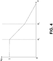
- FIG. 4 An example of such a gain reduction regime is illustrated in Figure 4 , with current wind turbine blade pitch ⁇ being shown on the x axes and the applied gain K p being shown on the y axes.
- a gain of 1 is applied, i.e. no gain reduction.
- the value of ⁇ will increase and eventually cross the first threshold value ⁇ 1 .
- the amount of gain applied will fall below 1 and accordingly the gain is reduced at a first rate of change.
- the applied gain is then reduced at a second rate of change when the pitch value is greater than ⁇ 2 .
- ⁇ 1 may be set to approximately 10 degrees and ⁇ 2 may be set to be approximately 30 degrees.
- the shutdown procedures may be initiated by the controller in response to the controller receiving a shutdown request.
- the controller may receive a request for an emergency shutdown.
- the described shutdown procedures are particularly appropriate for emergency shutdown scenarios as the wind turbine 1 is likely to be experiencing adverse environmental conditions, such as extreme wind gusts, and the wind turbine may also have been recently disconnected from the power grid leading to a removal of the generator braking toque as set out above.
- the wind turbine controller 40, 50 may initiate an emergency shutdown procedure without receiving an external request for emergency shutdown in the event that the controller detects an internal failure or other condition necessitating an emergency shutdown.
- the controllers, functions and logic elements described herein may be implemented as hardware components or as software executing on one or more processors located at the wind turbines or remotely.
- the one or more processors may comprise one or more special purpose processing devices such as an application specific integrated circuit (ASIC), a field programmable gate array (FPGA), a digital signal processor (DSP), network processor, or other similar devices.
- ASIC application specific integrated circuit
- FPGA field programmable gate array
- DSP digital signal processor
- the one or more processors are configured to perform the operations and methods described above, which may be carried out by a single processor or, alternatively, may be carried out by a number of processors connected together.
Description
- Embodiments of the present invention relate to methods and control systems for controlling the shutdown of a wind turbine, in particular to controlling the wind turbine shutdown in a dynamic and adaptive manner.
-
Figure 1 illustrates alarge wind turbine 1, comprising atower 10, awind turbine nacelle 20 positioned on top of thetower 10 and a rotor. The illustrated wind turbine rotor comprises threewind turbine blades 32 and ahub 34. Thehub 34 is located at a height H above the base of the tower and each of the threewind turbine blades 32 are mounted to the hub. Whilst the wind turbine rotor is shown as having three wind turbine blades, the wind turbine rotor could comprise a different number ofblades 32. Theblades 32 each have a length L. - The
hub 34 is typically connected to thenacelle 20 through a low speed shaft (not shown) extending from the front of thenacelle 20. The low speed shaft drives a gearbox (also not shown) which steps up the rotational speed and, in turn, drives an electrical generator within thenacelle 20 for converting the energy extracted from the wind by the rotatingblades 32 into electrical power output. In some embodiments, the wind turbine rotor may be directly coupled to the electrical generator, i.e. direct-drive turbines. - The
wind turbine blades 32 define a swept area A, which is the area of a circle delineated by the rotatingblades 32. The swept area dictates how much of a given air mass is intercepted by thewind turbine 1 and, thus, influences the power output of thewind turbine 1 and the forces and bending moments experienced by the components of theturbine 1 during operation. The turbine may stand onshore, as illustrated, or offshore. In the latter case the tower will be connected to a monopile, tripod, lattice or other foundation structure, and the foundation could be either fixed or floating. - Each wind turbine has a wind turbine controller that processes inputs from sensors and other control systems and generates output signals for actuators such as blade pitch actuators, generator torque controller, generator contactors, and yaw motors etc. The output signals generated by the wind turbine controller regulate the operation of the
wind turbine 1. - If the wind turbine controller receives an instruction or a request for the wind turbine to be shut down, then the wind turbine controller may generate output signals that cause the speed of the wind turbine rotor to decrease to zero. For example, the wind turbine controller may cause the blade pitch angle to be increased (towards 90 degrees) using the blade pitch actuators. This is commonly known as pitching the blade out, which causes the power output to be reduced since the pitched blade acts as an aerodynamic brake.
- A shutdown procedure may be initiated to change the
wind turbine 1 from an operational state to a static state, where the wind turbine rotor is stationary. The shutdown procedure may be initiated in order to avoid excessive loads on the components of thewind turbine 1, for example during extreme wind conditions and/or if the electric generator of thewind turbine 1 has been disconnected from the power grid. The combination of these two events is typically the worst case scenario for the loading of a wind turbine during a shutdown procedure. - Existing control techniques tend to implement wind turbine shutdown in a process whereby the wind turbine blades are pitched out towards a feathered position at a predetermined blade pitch change speed until the wind turbine blade is fully turned out of the wind to reduce power output, this may also take into account specific pitch angles of the individual blades. It has been appreciated that it would be desirable to provide an improved method and system for controlling the shutdown of a wind turbine that reduces the stresses induced by excessive loads on the wind turbine components.
-
US2015/377215 discloses a method and a system for managing loads on a wind turbine. The method includes receiving a signal relative to a yaw misalignment of the wind turbine, generating a yaw error signal based on the yaw misalignment, and comparing the yaw error signal to a first predetermined yaw error threshold value. The method further includes shutting down the wind turbine if the yaw error signal remains greater than the second predetermined yaw error threshold value beyond the predetermined period of time. - The invention is defined in the independent claims to which reference is now directed. Different embodiments are defined in the dependent claims.
- Embodiments of the invention relate generally to methods for controlling the operating parameters of a wind turbine during shutdown, controllers for implementing such methods and wind turbines including one or more of these controllers. In particular, it has been appreciated that certain loads experienced during the shutdown of a wind turbine can be reduced by providing improved control of the pitching of the blades of a wind turbine. This may reduce the required strength of the turbine elements or components, or alternatively may increase the expected lifetime of the relevant components.
- According to a first aspect of the invention, there is provided a method of controlling shutdown of a wind turbine having a rotor, the rotor comprising one or more wind turbine blades, the method comprising: dynamically determining a rotor speed reference; obtaining a measure of the rotor speed of the rotor; obtaining a measure of a fore-aft movement of the wind turbine tower; determining an error between the rotor speed reference and the rotor speed of the rotor; and controlling a pitch of one or more of the wind turbine blades based on the determined error and the measured fore-aft movement of the wind turbine tower.
- By controlling the blade pitch using a reference rotor speed that is dynamically determined, rotor loading can be reduced quickly and efficiently in view of the current conditions that the wind turbine is subject to; in an embodiment this may be obtained by closed feedback loop control. This in turn reduces the extreme loading that the wind turbine would be expected to experience during the controlled shutdown, which may be taken into account when considering the design loads at the design stage of producing the wind turbine, and improve the safety of the wind turbine, in particular with reference to the stresses on the drivetrain and gearbox components.
- Moreover, the method comprises obtaining a measure of a fore-aft movement of the wind turbine tower, and controlling the pitch of one or more of the wind turbine blades in further dependence on the measured fore-aft movement of the wind turbine tower. During shutdown the turbine is prone to fore-aft movement, and by taking this movement into account during the shutdown the loading that the wind turbine tower experiences due to the fore-aft movement is directly taken into account, and thereby ensuring quickly and efficiently shutdown and at the same time keeping the loads of the tower structure and/or tower foundation down.
- The method further comprises determining whether the rotor speed of the rotor is increasing, wherein the dynamic determination of the rotor speed reference comprises maintaining a constant rotor speed reference value when the rotor speed of the rotor is determined to be increasing. This improves the control of the pitch actuation when the error between the rotor speed reference and the measured rotor speed of the rotor is large by controlling the rotor speed reference to reduce the time taken for the method to regain control of the speed of the rotor. In this manner, the rotor speed reference may be dynamically determined because it is determined at least in part based on an evaluation of the rotor speed of the rotor.
- Optionally, the dynamic determination of the rotor speed reference may comprise setting the rotor speed reference value to be equal to the rotor speed of the rotor when the rotor speed of the rotor is determined to be less than the rotor speed reference. This acts to stop the method from attempting to increase the rotor speed of the rotor where the wind turbine blades are naturally slowing down more quickly than the dynamically determined reduction of the rotor speed reference value.
- Optionally, the dynamic determination of the rotor speed reference may comprise progressively ramping the rotor speed reference down to zero when the rotor speed of the rotor is determined to be both higher than the rotor speed reference and to not be increasing. This advantageously reduces the speed of the rotor to zero when the error between the rotor speed reference and the measured rotor speed is not too large and thus when the method has control of the speed of the rotor.
- Optionally, a rate of change of the wind turbine blade pitch may be reduced whilst the wind turbine tower is determined to be moving into the wind due to the fore-aft movement and/or wherein the rate of change of the wind turbine blade pitch is increased whilst the wind turbine tower is determined to be moving in the direction of the wind due to the fore-aft movement.
- In this manner, the wind loading on the wind turbine blades may be maintained whilst the tower is moving forwards by either not pitching the wind turbine blade out any further, or by reducing the speed at which the wind turbine blade is pitched out. This change in the pitching out of the wind turbine blade will provide a comparatively large wind loading and wind resistance on the wind turbine blades that will act to counter the motion of the wind turbine into the wind. Conversely, the wind loading on the wind turbine blades may be reduced whilst the tower is moving backwards, i.e. in the wind direction, by increasing the speed at which the wind turbine blades are pitched out and moved towards the feathered position. This will reduce the wind loading that would otherwise contribute to the speed of the aft movement of the wind turbine tower and thus would increase or sustain the tower oscillations in the plane parallel to the wind direction.
- Optionally, the dynamic determining of the rotor speed reference may further comprise modifying the rotor speed reference based on the measured fore-aft movement of the wind turbine tower. In such a method, the contribution to the control of the wind turbine blade pitching in view of the fore-aft movement of the wind turbine tower may be included in the control method by simply modifying the dynamically determined rotor speed reference.
- Optionally, the method may further comprise determining an acceleration of the rotor based on the rotor speed of the rotor; wherein a rate of change of the wind turbine blade pitch is increased proportional to the acceleration when the acceleration is above a given threshold. Accordingly, the level of wear and fatigue experienced by the drivetrain and gearbox components during shutdown of the wind turbine may be limited.
- Optionally, a gain reduction may be applied to a rate of change of the wind turbine blade pitch as a function of the pitch of the one or more wind turbine blades. This enables the use of a single nominal tuning that can then be automatically scaled to fit the various possible operating points of the turbine. In this context, an operating point may be defined by one or more measured quantities, for example the average wind speed, rotor speed, pitch angle or electrical power of the wind turbine.
- Optionally, the gain reduction may be a progressive gain reduction and a rate of the progressive gain reduction may be based on one or more threshold angles of the pitch of one or more of the wind turbine blades so that the rate of pitch change may be altered as the blade moves towards the feathered position.
- Optionally, the method may apply no gain reduction if the pitch is below a first threshold angle, a first rate of progressive gain reduction may be applied if the pitch is between the first threshold angle and a second threshold angle and a second rate of progressive gain reduction may be applied if the pitch is above the second threshold angle; wherein the first rate of progressive gain reduction is higher than the second rate of progressive gain reduction. In this manner, the rate of the blade pitch change may be reduced as the blade moves towards the feathered position, with the loads on the system being minimised throughout the shutdown process.
- Optionally, the pitch of each of the one or more wind turbine blades may be controlled individually. This enables rotor blade loads to be compensated for where there may be uneven loading on the rotor, for example the tilt and yaw moments at the main bearing of the wind turbine nacelle. This active control during wind turbine shutdown acts to prevent structural failure of the main components due to extreme loads and would also enable shutdown of the wind turbine when the blades are pitched at different positions.
- According to a second aspect of the invention, there may also be provided a controller for a wind turbine having a rotor, the rotor comprising one or more wind turbine blades, wherein the controller is configured to implement any of the above methods for controlling wind turbine shutdown. Such a controller will enable the blade pitch to be controlled based on a closed feedback loop control with a reference rotor speed that is dynamically determined so that rotor loading can be reduced quickly and efficiently in view of the current conditions that the wind turbine is subject to. This controller will act to reduce the extreme loading that the wind turbine may be expected to experience during the controlled shutdown. This can then be taken into account when considering the design loads at the design stage of producing the wind turbine and can improve the safety of the wind turbine.
- Optionally, the controller may be configured to cause any of the above methods to be implemented in response to the controller receiving an emergency shutdown request. The emergency shutdown request may indicate, for example, that a failure has been detected in the controller and accordingly the shutdown methods may be tuned for the loads that would be expected to be experienced during such an emergency shutdown operation.
- According to a third aspect of the invention, there may be provided a wind turbine comprising a rotor and one or more controllers according to the second aspect of the invention, wherein the rotor comprises one or more wind turbine blades. The controller may be included in a wind turbine. Where a single wind turbine comprises a plurality of controllers, the controllers may provide redundancy in the operation and control of the wind turbine during shutdown, for example in the event that one of the controllers fails.
- Optionally, a wind turbine according to the third aspect of the invention may comprise one or more controllers each configured to control the pitch of a respective wind turbine blade of the one or more of the wind turbine blades. In this manner each controller may provide pitch control for a different blade so that the pitching of the wind turbine blades may be controlled individually and independently. This enables rotor blade fatigue loads to be compensated for where there may be uneven loading on the rotor, for example the tilt and yaw moments at the main bearing of the wind turbine nacelle.
- According to a fourth aspect of the invention, there may also be provided a corresponding computer program that when executed on a wind turbine controller causes the wind turbine controller to carry out any of the methods described herein.
- The invention will now be further described by way of example only and with reference to the accompanying figures in which:
-
Figure 1 is a schematic view of a wind turbine; -
Figure 2 is an example of a controller according to a first example of the invention; -
Figure 3 is an example of a controller according to a second example of the invention; and -
Figure 4 is a graph illustrating a gain control regime according to the second example of the invention. - The process of shutting down a
wind turbine 1 will not always take place in steady wind conditions and accordingly the method of the control system is preferably able to safely shut the wind turbine down in less favourable conditions, and even extreme conditions. For example, it is desirable that the method of controlling the shutdown of thewind turbine 1 be able to quickly and safely stop the rotation of the wind turbine rotor, even in gusty conditions. - One example of such gusty conditions is commonly known as a Mexican hat wind gust for its similarity to the cross-section of a sombrero. In this type of wind gust, the steady wind speed drops briefly to a low, then quickly accelerates to a peak level before dropping again to a low and then recovering to the steady wind speed. The electric generator of the
wind turbine 1 may be disconnected from the power grid if there is an electrical failure or simply a lack of demand; however, this disconnection removes the counter torque of the electric generator from the wind turbine rotor. This reduces the resistance to the rotation of the rotor and thus allows the speed of the rotor to increase further. - If an existing wind turbine shutdown procedure, of the type described in the above background, were to be initiated whilst the speed of the rotor was increasing in this manner, then the pitching of the
wind turbine blades 32 would not be in control of the wind turbine rotor speed. This would mean that the shutdown of the wind turbine could not be adapted to minimise the loads experienced by thewind turbine 1. Furthermore, whilst simply pitching the wind turbine blades out as fast as possible may quickly reduce the rotation of the wind turbine rotor, the sudden change in pitch will also unbalance the wind turbine with respect to the wind loading on the wind turbine, which may cause the wind turbine to move forwards (i.e. into and against the wind direction) and backwards (i.e. out of and with the wind direction). This fore-aft oscillation of the wind turbine will cause undesirable stresses in thewind turbine tower 10. - In the present invention, the wind turbine shutdown procedure is advantageously completed under a closed loop feedback control system.
Figure 2 illustrates a control system that may be implemented in a wind turbine controller for controlling the shutdown of a wind turbine according to a general embodiment of the invention. Thewind turbine controller 40 comprises a rotorspeed reference unit 42, an error value controller 44 and aspeed controller 46. Thewind turbine controller 40 is preferably local to thewind turbine 1, for example in thetower 10 or in thenacelle 20, this reduces the possibility of communication issues preventing the controller from being able to cause thewind turbine 1 to perform a controlled shutdown. However, it will be appreciated that thewind turbine controller 40 may be located elsewhere. - When the
controller 40 receives a signal instructing the controller to initiate a shutdown procedure, the rotorspeed reference unit 42 will generate an initial rotor speed reference value. The rotorspeed reference unit 42 receives a measure of the rotor speed of the wind turbine rotor and uses this measure as an input for dynamically determining a rotor speed reference value. It will be appreciated that the measure of the rotor speed may be obtained by integration of the output of a sensor that measures the acceleration of the rotor. - The initial rotor speed reference value may be set to be equal to the measured rotor speed of the wind turbine rotor, to a filtered version of the measured rotor speed of the wind turbine rotor, or alternatively it may be set to the value of a target rotor speed that was in operation immediately prior to the
controller 40 receiving a shutdown instruction. This rotor speed reference value is then communicated to the error value controller 44, which also receives the measure of the rotor speed of the wind turbine rotor. The error value controller 44 compares these two inputs to calculate an error between the rotor speed reference and the rotor speed of the wind turbine rotor. - The error value controller 44 is preferably a proportional integral derivative (PID) controller, whereby the proportional term accounts for the current error value, the integral term accounts for the previous error values and the derivative term looks forward to possible future values.
- However, the parameters of the PID controller may optionally be set such that the one or two of the proportional, integral or derivative terms are set to zero.
- The determined error is then communicated to the
speed controller 46, which produces a pitch control signal for controlling the pitch of thewind turbine blades 32 based on the determined error. If the initial rotor speed reference value is set to be equal to the measured rotor speed of the wind turbine rotor at the first instance then there will initially be no determined error and accordingly thespeed controller 46 will not initially cause the pitch of thewind turbine blades 32 to change. The rotorspeed reference unit 42 will then continuously generate new rotor speed reference values for use in thecontroller 40 to produce pitch control signals that quickly and safely transition thewind turbine 1 from an operational state to a shutdown state where the wind turbine rotor is static and the pitch angle of thewind turbine blades 32 has been increased to an angle of roughly 90 degrees, i.e. the feathered position. - The rotor speed reference value is dynamically determined in the sense that it is determined based on measured parameters of the wind turbine (for example rotor speed) and/or measured parameters of the external conditions (for example wind speed). This enables the
controller 40 to modify the wind turbine shutdown procedure in order to maintain control of the rotor speed and minimise the loads experienced by thewind turbine 1. - In connection with dynamically determining the rotor speed reference value, the rotor
speed reference unit 42 monitors the rotor speed input to determine if the speed of the rotor is increasing or not. If it is determined that the rotor speed is increasing, then the rotorspeed reference unit 42 adapts the existing continuous generation of new rotor speed reference values to hold the rotor speed reference constant. - Whilst it may seem counterintuitive to prevent the rotor speed reference value from decreasing while the controller is attempting to reduce the speed of the rotor to zero, continuing to reduce the rotor speed reference in this scenario would cause the determined error to become comparatively large. This in turn would cause the
speed controller 46 to attempt to change the pitch of thewind turbine blades 32 by a large amount and/or quickly, which is undesirable since it may cause undue stresses on the pitch actuation system and/or cause thewind turbine tower 10 to oscillate due to the rapid change in the wind loading of thewind turbine blades 32. As such, there is a trade-off between the stresses induced in the rotor and the stresses induced in the tower during the shutdown procedure. - Moreover, a large error value such as this would indicate that the control system is not actually performing the shutdown in a controlled manner. Accordingly, by holding the rotor speed reference value constant, the error is prevented from becoming too large and control of the shutdown process is sustained. The
controller 40 maintains this constant rotor speed reference until it is determined that the rotor speed of the rotor is no longer increasing. However, it is important to note that thespeed controller 46 will continue to pitch thewind turbine blades 32 out whilst the rotor speed reference value is held constant since the measured rotor speed will still be higher and increasing. - When it is determined that the rotor speed of the rotor is no longer increasing, the rotor speed reference value may be reduced by the continuous generation of new rotor speed reference values, for example the rotor speed reference may be progressively ramped from the previous value to zero in a linear or non-linear manner.
- Additionally a further example of dynamically determining the rotor speed reference value comprises causing the rotor
speed reference unit 42 to set the rotor speed reference value to be equal to the measured rotor speed of thewind turbine rotor 32 when it is determined that the measured rotor speed of the rotor is determined to be less than the rotor speed reference value. In this way, thecontroller 40 acts to prevent the determined error from causing thespeed controller 46 to pitch the blades back into the wind and attempting to speed therotor 32 up. Thecontroller 40 will then continue to continuously generate new rotor speed reference values in the previous manner. - Each of the above control strategies contribute to reduce the maximum rotor speed during shutdown, which in turn reduces the stress on drivetrain and gearbox components. This increases the safety of the wind turbine design and reduces the required design loads for designing the
tower 10 and foundation of thewind turbine 1. - In the examples above, the invention has been described using a single
wind turbine controller 40 to control the collective pitch of each of thewind turbine blades 32 of thewind turbine 1. In one embodiment, thewind turbine 1 is provided with arespective controller 40 for each of the wind turbine blades. In this way, the pitching of the threewind turbine blades 32 of a wind turbine may be individually controlled thus allowing rotor blade fatigue loads to be compensated for where there may be uneven loading on the rotor, for example the load due to the tilt and yaw moments at the main bearing of the wind turbine nacelle. Alternatively or additionally, themultiple controllers 40 may be used to provide redundancy in the control system, for example so that the remainingcontrollers 40 may take over in the event that one of the controllers is damaged by a lightning strike or another fault. -
Figure 3 illustrates further elements of a control system that may be implemented in a wind turbine controller for controlling the shutdown of a wind turbine according to an embodiment of the invention. Thewind turbine controller 50 explicitly illustrates a fore-aft tower damper 54, and also comprises a rotorspeed reference unit 42, an error value controller 44 and aspeed controller 46, with like reference numbers being used for like components with respect to thewind turbine controller 40. Accordingly, whilst the above description ofwind turbine controller 40 will not be repeated herein, it applies equally to the corresponding components ofwind turbine controller 50. -
Wind turbine controller 50 further comprises a lowpass filter unit 52, a fore-aft tower damper 54, a timederivative unit 56, anacceleration limiter 58, and again scheduler 60. It will be appreciated from the below that each of these units may be used individually, and accordingly thewind turbine controller 40 may be modified to include one or more of these additional components without including the remaining components. For example,wind turbine controller 40 may be modified to include a fore-aft tower damper 54 without theacceleration limiter 58 or thegain scheduler 60. Other combinations of these units are of course possible as will be appreciated by the person skilled in the art. - In the example of
Figure 3 , the measure of the rotor speed is received at alow pass filter 52 prior to being communicated to the error value controller 44. This acts to reduce the high frequency fluctuations in the signal communicating the measured rotor speed and thus smooths the value of the rotor speed signal. In turn, this advantageously tempers the volatility of the determined error signal generated by the error value controller 44 and the pitch control signal generated by thespeed controller 46 and thus reduces the strain and fatigue induced in the pitch control actuators during the shutdown procedure. The measure of the rotor speed that is received by the rotorspeed reference unit 42 is shown as being received prior to thelow pass filter 52; however, it will be appreciated that this input could instead be provided from the output of thelow pass filter 52. - The fore-
aft tower damper 54 receives a measure of the movement of thewind turbine tower 10 and causes thewind turbine controller 50 to adapt the pitch control signal accordingly. The measure of tower movement may be derived from a position sensor, a velocity sensor or an acceleration sensor as will be appreciated by the person skilled in the art. - While the fore-aft damper is illustrated in connection with the embodiment of
Figure 3 , it should be understood that the disclosure of the fore-aft damper is equally relevant for the general embodiment ofFigure 2 . - The adaptation to the pitch control by the fore-
aft tower damper 54 is preferably proportional to the lateral (down-wind) velocity at the top of thewind turbine tower 10; however, this may of course be determined from position or acceleration measurements, using differentiation or integration respectively, or a combination of position, velocity and acceleration measurements. In one example, the pitch angle may be altered in more general terms in line with the following equation, where Ka, Kv and Kp are typically real non-zero numbers corresponding to the respective acceleration, velocity and position gains used to tune the control scope of the damping of the tower movement:
- In one implementation, an accelerometer may be placed on the wind turbine tower, for example at the top of the wind turbine tower, and configured to obtain a measure of the acceleration in the fore-aft (forwards and backwards) plane. This acceleration may then be converted into a velocity using a velocity estimator, such as a low pass filter that is appropriately tuned so that the resonant frequency of the tower is the region around which the low pass filter acts like a leaky integrator. However, other integrators or other sensor types may be used as described above.
- In one example, the fore-
aft tower damper 54 may modify the pitch control signal to reduce the rate of change of the wind turbine blade pitch in the event that the movement of thewind turbine tower 10 is determined to be into the wind, i.e. in the fore direction against the wind direction. By reducing the rate of change of pitch in this manner, the pitch angle will be comparatively low with respect to the situation if the fore-aft tower damper 54 had not modified the pitch. This lower pitch angle means that thewind turbine blades 32 will experience a greater degree of wind loading, which acts to counter the movement of thewind turbine tower 10 into the wind and therefore dampens the oscillation of the tower in the fore-aft plane. Although this may increase the speed of the rotor by comparison, the reduced wind turbine tower loads provide a trade-off that may be beneficial in the design of thewind turbine 1 as a whole. - Additionally or alternatively, the fore-
aft tower damper 54 may modify the pitch control signal to increase the rate of change of the wind turbine blade pitch in the event that the movement of thewind turbine tower 10 is determined to be in the same direction as the wind direction, i.e. in the aft direction. By increasing the rate of change of pitch in this manner, the pitch angle will be comparatively high with respect to the situation if the fore-aft tower damper 54 had not modified the pitch. This higher pitch angle means that thewind turbine blades 32 will experience a lower degree of wind loading, which acts to minimise any acceleration of thewind turbine tower 10 in the wind direction due to the wind loading. Therefore, this further acts to dampen the oscillation of thewind turbine tower 10 in the fore-aft plane. - In
Figure 3 , the fore-aft tower damper 54 is shown as feeding into an adder that modifies the pitch control signal of thespeed controller 46. In an alternative example, the output of the fore-aft tower damper 54 may instead be fed into the rotorspeed reference unit 42 and used to modify the rotor speed reference value in order to modify the resultant pitch control signal. - The example of
Figure 3 is further provided with anacceleration limiter 58 that receives the measure of the wind turbine rotor speed via a timederivative unit 56. The timederivative unit 56 will convert the measure of the wind turbine rotor speed into a measure of the acceleration of the wind turbine rotor. The timederivative unit 56 may act as a one-step derivative or use any other corresponding approach, for example lead networks or specific filters. - The
acceleration limiter 58 is provided to curb extreme accelerations that may arise in the wind turbine rotor by causing the pitch control signal to be modified. As shown inFigure 3 , theacceleration limiter 58 may communicate this modification to thespeed controller 46. Alternatively the modification may operate on the output of thespeed controller 46, i.e. at a downstream point between thespeed controller 46 and the wind turbine blade pitch actuators, in this case the output arrow from theacceleration limiter 58 inFigure 3 would be directed to the summation point to the right of thespeed controller 46 rather than to the speed controller itself. This may be by theacceleration limiter 58 providing an additional offset to the pitch control signal or by applying a given level of gain to the pitch control signal. - In one example, the
acceleration limiter 58 has a dead zone between an acceleration of zero and a given threshold acceleration whereby no gain modification is applied for accelerations below the given threshold. When the acceleration is determined to be above the threshold, a proportional gain modification may be applied such that the pitch control signal, and therefore the rate of change in pitch of thewind turbine blades 32, is increased in proportion to the amount that the acceleration is above the given threshold. This proportional gain modification may be linear or non-linear. - In another example, the
acceleration limiter 58 operates the dead zone such that a zero pitch control signal offset is output to be summed with the output of thespeed controller 46 when the level of acceleration is determined to be below a given threshold acceleration and wherein the pitch control signal offset that it output to be summed with the output of thespeed controller 46 is proportional to the amount that the acceleration is over the given threshold when the acceleration is above the given threshold. - By increasing the rate at which the
wind turbine blades 32 are pitched out using the examples described above, the maximum acceleration of the wind turbine rotor is controlled during the shutdown procedure of the invention to keep the acceleration levels within acceptable boundaries. Accordingly, the acceleration limiter may preferably act to override the pitching control scheme of the rotorspeed reference unit 42 and thespeed controller 46 in situations where there is a large acceleration that requires a large reaction in terms of pitch control. - The
acceleration limiter 58 may include a filter to smooth the value of the gain modification that is output by theacceleration limiter 58. The filter acts to prevent a sudden change in the gain modification in the event that the acceleration rapidly drops back into the dead zone where no gain modification is applied. - As shown in
Figure 3 , a wind turbine controller according to the invention may also be provided with again scheduler 60. Thegain scheduler 60 receives a measure of the current pitch angle of thewind turbine blades 32 as an input and outputs a gain control signal to scale the action of thespeed controller 46 to match the various possible operating points of thewind turbine 1. The measure of the current pitch angle may be received from a pitch position sensor located on one or more of thewind turbine blades 32, with the pitch value ranging from 0 degrees to 90 degrees and the blade being fully pitched out at a pitch angle of 90 degrees. - In one implementation, the
gain scheduler 60 may provide a degree of gain reduction to scale down the pitch control signal and/or the rate of change of the wind turbine blade pitch based on the measure of the current pitch of thewind turbine blade 32. This gain reduction may be applied as a linear gain reduction with the rate of gain reduction changing at a number of thresholds of the current pitch angle. - An example of such a gain reduction regime is illustrated in
Figure 4 , with current wind turbine blade pitch Θ being shown on the x axes and the applied gain Kp being shown on the y axes. In the first region, where the current pitch is determined to be less than a first threshold of Θ1, a gain of 1 is applied, i.e. no gain reduction. As the wind turbine blade is pitched out during the shutdown procedure, the value of Θ will increase and eventually cross the first threshold value Θ1. At this point, the amount of gain applied will fall below 1 and accordingly the gain is reduced at a first rate of change. The applied gain is then reduced at a second rate of change when the pitch value is greater than Θ2. - As can be seen from
Figure 4 , in this example the first rate of change is higher than the second rate of change. This means that the aggressiveness of the pitch control regime is reduced as the pitching of thewind turbine blades 32 nears the feathered position. In one example, Θ1 may be set to approximately 10 degrees and Θ2 may be set to be approximately 30 degrees. - As described above, the shutdown procedures may be initiated by the controller in response to the controller receiving a shutdown request. In particular, the controller may receive a request for an emergency shutdown. The described shutdown procedures are particularly appropriate for emergency shutdown scenarios as the
wind turbine 1 is likely to be experiencing adverse environmental conditions, such as extreme wind gusts, and the wind turbine may also have been recently disconnected from the power grid leading to a removal of the generator braking toque as set out above. - In these situations, it is especially important that the
wind turbine 1 is shut down safely whilst also attempting to minimise the instantaneous loads that the components of thewind turbine 1 experience during the shutdown. As will be appreciated, thewind turbine controller - The controllers, functions and logic elements described herein may be implemented as hardware components or as software executing on one or more processors located at the wind turbines or remotely. The one or more processors may comprise one or more special purpose processing devices such as an application specific integrated circuit (ASIC), a field programmable gate array (FPGA), a digital signal processor (DSP), network processor, or other similar devices. The one or more processors are configured to perform the operations and methods described above, which may be carried out by a single processor or, alternatively, may be carried out by a number of processors connected together.
Claims (15)
- A method of controlling shutdown of a wind turbine (1) having a rotor, the rotor comprising one or more wind turbine blades (32), the method comprising:dynamically determining a rotor speed reference;obtaining a measure of the rotor speed of the rotor;obtaining a measure of a fore-aft movement of the wind turbine tower;determining an error between the rotor speed reference and the rotor speed of the rotor; andcontrolling a pitch of one or more of the wind turbine blades based on the determined error and the measured fore-aft movement of the wind turbine tower; characterized in that the method further comprising determining whether the rotor speed of the rotor is increasing, wherein the dynamic determination of the rotor speed reference comprises maintaining a constant rotor speed reference value when the rotor speed of the rotor is determined to be increasing.
- A method according to claim 1, wherein the dynamic determination of the rotor speed reference comprises setting the rotor speed reference value to be equal to the rotor speed of the rotor when the rotor speed of the rotor is determined to be less than the rotor speed reference value.
- A method according to any of claims 1 to 2, wherein the dynamic determination of the rotor speed reference comprises progressively ramping the rotor speed reference down to zero when the rotor speed of the rotor is determined to be both higher than the rotor speed reference value and to not be increasing.
- A method according to any of the preceding claims, wherein a rate of change of the wind turbine blade pitch is reduced whilst the wind turbine tower is determined to be moving into the wind due to the fore-aft movement and/or wherein the rate of change of the wind turbine blade pitch is increased whilst the wind turbine tower is determined to be moving in the direction of the wind due to the fore-aft movement.
- A method according to any of the preceding claims, wherein the dynamic determining of the rotor speed reference further comprises modifying the rotor speed reference based on the measured fore-aft movement of the wind turbine tower.
- A method according to any preceding claim, further comprising determining an acceleration of the rotor based on the rotor speed of the rotor; wherein a rate of change of the wind turbine blade pitch is increased proportional to the acceleration when the acceleration is above a given threshold.
- A method according to any preceding claim, wherein a gain reduction is applied to a rate of change of the wind turbine blade pitch as a function of the pitch of the one or more wind turbine blades.
- A method according to claim 7, wherein the gain reduction is a progressive gain reduction and a rate of the progressive gain reduction is based on one or more threshold angles of the pitch of one or more of the wind turbine blades.
- A method according to claim 7 or 8, whereby no gain reduction is applied if the pitch is below a first threshold angle, a first rate of progressive gain reduction is applied if the pitch is between the first threshold angle and a second threshold angle and a second rate of progressive gain reduction is applied if the pitch is above the second threshold angle; wherein the first rate of progressive gain reduction is higher than the second rate of progressive gain reduction.
- A method according to any preceding claim, wherein the pitch of each of the one or more wind turbine blades is controlled individually.
- A controller (40, 50) for a wind turbine (1) having a rotor, the rotor comprising one or more wind turbine blades (32), wherein the controller is configured to cause the method of any of claims 1 to 10 to be implemented during shutdown of the wind turbine.
- A controller according to claim 11, wherein the controller is configured to cause the method of any of claims 1 to 10 to be implemented in response to the controller receiving an emergency shutdown request.
- A wind turbine (1) comprising a rotor and one or more controllers (40, 50) according to claim 11 or 12, wherein the rotor comprises one or more wind turbine blades (32).
- A wind turbine according to claim 13, wherein the one or more controllers are each configured to control the pitch of a respective wind turbine blade of the one or more of the wind turbine blades.
- A computer program that, when executed on a wind turbine controller, causes the wind turbine controller to carry out the method of any of claims 1 to 10.
Applications Claiming Priority (2)
| Application Number | Priority Date | Filing Date | Title |
|---|---|---|---|
| DKPA201670629 | 2016-08-17 | ||
| PCT/DK2017/050262 WO2018033190A1 (en) | 2016-08-17 | 2017-08-14 | Dynamic controlled wind turbine shutdown |
Publications (2)
| Publication Number | Publication Date |
|---|---|
| EP3500751A1 EP3500751A1 (en) | 2019-06-26 |
| EP3500751B1 true EP3500751B1 (en) | 2021-03-24 |
Family
ID=61196386
Family Applications (1)
| Application Number | Title | Priority Date | Filing Date |
|---|---|---|---|
| EP17754254.5A Active EP3500751B1 (en) | 2016-08-17 | 2017-08-14 | Dynamic controlled wind turbine shutdown |
Country Status (5)
| Country | Link |
|---|---|
| US (1) | US10890159B2 (en) |
| EP (1) | EP3500751B1 (en) |
| CN (1) | CN109891091B (en) |
| ES (1) | ES2863671T3 (en) |
| WO (1) | WO2018033190A1 (en) |
Families Citing this family (12)
| Publication number | Priority date | Publication date | Assignee | Title |
|---|---|---|---|---|
| CN109891091B (en) | 2016-08-17 | 2020-09-15 | 维斯塔斯风力系统集团公司 | Dynamically controlled wind turbine shutdown |
| US10927812B2 (en) * | 2019-02-19 | 2021-02-23 | General Electric Company | Method of dynamically adjusting a rate of change of a rotor speed set point during wind turbine shutdown |
| EP3976959A1 (en) * | 2019-05-28 | 2022-04-06 | Vestas Wind Systems A/S | Reduction of edgewise vibrations using blade load signal |
| CN112412697B (en) * | 2019-08-23 | 2023-04-07 | 新疆金风科技股份有限公司 | Variable pitch demand rate correction method and device and wind generating set |
| ES2812374B2 (en) * | 2019-09-16 | 2022-02-17 | Esteyco S A | CONTROL PROCEDURE OF A FLOATING TYPE OFFSHORE WIND TURBINE, AS WELL AS THE SYSTEM AND THE WIND TURBINE THAT INCORPORATES THIS PROCEDURE |
| CN110761946B (en) * | 2019-10-22 | 2021-08-03 | 许昌许继风电科技有限公司 | Fan tower vibration control method and device |
| GB2590388B (en) * | 2019-12-13 | 2022-02-16 | Equinor Energy As | Blade pitch controller for a wind turbine |
| CN113090452B (en) * | 2019-12-23 | 2022-07-05 | 新疆金风科技股份有限公司 | Wind generating set and blade feathering control method and device thereof |
| CN114945746A (en) | 2020-01-16 | 2022-08-26 | 维斯塔斯风力系统集团公司 | Pitch control of wind turbine blades in standby mode |
| CN112253386A (en) * | 2020-10-15 | 2021-01-22 | 华能酒泉风电有限责任公司 | Wind power generation equipment and blade self-variable pitch control method, system and device thereof |
| CN112855434B (en) * | 2021-01-29 | 2022-04-01 | 三一重能股份有限公司 | Control method and device for wind turbine generator blade, electronic equipment and storage medium |
| CN114000974B (en) * | 2021-10-31 | 2023-11-07 | 重庆科凯前卫风电设备有限责任公司 | Redundancy control method based on variable pitch variable speed wind generating set |
Family Cites Families (16)
| Publication number | Priority date | Publication date | Assignee | Title |
|---|---|---|---|---|
| US4189648A (en) | 1978-06-15 | 1980-02-19 | United Technologies Corporation | Wind turbine generator acceleration control |
| US4193005A (en) * | 1978-08-17 | 1980-03-11 | United Technologies Corporation | Multi-mode control system for wind turbines |
| FR2869122B1 (en) | 2004-04-16 | 2006-06-02 | Renault V I Sa | METHOD FOR CONTROLLING THE TRACK OF A VEHICLE |
| ES2301400B1 (en) | 2006-11-17 | 2009-05-01 | GAMESA INNOVATION & TECHNOLOGY S.L. | METHOD OF REDUCTION OF LOADS IN AN AEROGENERATOR. |
| DE102008012957A1 (en) | 2008-03-06 | 2009-09-10 | Repower Systems Ag | Method for operating a wind turbine and wind turbine |
| DK2107236T3 (en) * | 2008-04-02 | 2015-02-02 | Siemens Ag | Method for attenuating tower vibration of a wind turbine and wind turbine control system |
| DK201070274A (en) | 2009-10-08 | 2011-04-09 | Vestas Wind Sys As | Control method for a wind turbine |
| ES2633816T3 (en) * | 2010-08-23 | 2017-09-25 | Vestas Wind Systems A/S | Method of operation of a wind turbine and wind turbine |
| DE102010044433A1 (en) * | 2010-09-06 | 2012-03-08 | Nordex Energy Gmbh | Method for controlling the speed of a wind turbine |
| US9810199B2 (en) * | 2011-11-21 | 2017-11-07 | Vestas Wind Systems A/S | Shutdown controller for a wind turbine and a method of shutting down a wind turbine |
| CA2871278C (en) * | 2012-05-02 | 2018-06-12 | General Electric Company | System and method for stopping the operation of a wind turbine |
| US9644608B2 (en) | 2012-12-24 | 2017-05-09 | General Electric Company | Method and system for shutting down a wind turbine |
| EP2784303B1 (en) * | 2013-03-27 | 2016-11-02 | Alstom Renovables España, S.L. | Method of operating a wind turbine |
| ES2683210T3 (en) | 2013-04-22 | 2018-09-25 | Vestas Wind Systems A/S | Method to control a wind turbine during shutdown |
| US9745958B2 (en) * | 2014-06-30 | 2017-08-29 | General Electric Company | Method and system for managing loads on a wind turbine |
| CN109891091B (en) | 2016-08-17 | 2020-09-15 | 维斯塔斯风力系统集团公司 | Dynamically controlled wind turbine shutdown |
-
2017
- 2017-08-14 CN CN201780064119.7A patent/CN109891091B/en active Active
- 2017-08-14 EP EP17754254.5A patent/EP3500751B1/en active Active
- 2017-08-14 WO PCT/DK2017/050262 patent/WO2018033190A1/en unknown
- 2017-08-14 ES ES17754254T patent/ES2863671T3/en active Active
- 2017-08-14 US US16/326,301 patent/US10890159B2/en active Active
Non-Patent Citations (1)
| Title |
|---|
| None * |
Also Published As
| Publication number | Publication date |
|---|---|
| US20190203692A1 (en) | 2019-07-04 |
| EP3500751A1 (en) | 2019-06-26 |
| CN109891091A (en) | 2019-06-14 |
| ES2863671T3 (en) | 2021-10-11 |
| US10890159B2 (en) | 2021-01-12 |
| CN109891091B (en) | 2020-09-15 |
| WO2018033190A1 (en) | 2018-02-22 |
Similar Documents
| Publication | Publication Date | Title |
|---|---|---|
| EP3500751B1 (en) | Dynamic controlled wind turbine shutdown | |
| CN110446853B (en) | System and method for managing torsional oscillations of a wind turbine tower | |
| US9970413B2 (en) | Wind turbine with a load controller | |
| US9528495B2 (en) | Smart power management during voltage dip in wind turbines | |
| US8803351B2 (en) | Control method for a wind turbine | |
| US8487462B2 (en) | Methods for controlling a wind turbine connected to the utility grid, wind turbine and wind park | |
| EP3728832B1 (en) | Thrust balance control of a multirotor wind turbine based on constraints | |
| US20120139240A1 (en) | Method for reducing loads in a wind turbine | |
| US20110156393A1 (en) | Wind turbine generator, active damping method thereof, and windmill tower | |
| EP3545189B1 (en) | Improvements relating to wind turbines having blades equipped with boundary layer control system | |
| US20130177418A1 (en) | Method for adjusting the rotational speed of a wind turbine and wind turbine | |
| WO2015048972A1 (en) | Safe mode operation at high yaw error | |
| WO2013132635A1 (en) | Output control device and output control method for windmill | |
| JP5455890B2 (en) | Wind turbine generator control device, wind turbine generator system, and wind turbine generator control method | |
| KR101141090B1 (en) | Control device for wind power generator, wind farm, and control method of wind power generator | |
| CN116154804A (en) | Fan-water turbine primary frequency modulation control method considering standby flexibility | |
| EP3987172A1 (en) | Method of shutting down a wind turbine | |
| US11598310B2 (en) | Method for controlling a wind turbine, wind turbine, and wind park | |
| DK202170577A1 (en) | Controller for a wind turbine | |
| CN115370529A (en) | Method for controlling a wind energy installation, wind energy installation and wind park |
Legal Events
| Date | Code | Title | Description |
|---|---|---|---|
| STAA | Information on the status of an ep patent application or granted ep patent |
Free format text: STATUS: UNKNOWN |
|
| STAA | Information on the status of an ep patent application or granted ep patent |
Free format text: STATUS: THE INTERNATIONAL PUBLICATION HAS BEEN MADE |
|
| PUAI | Public reference made under article 153(3) epc to a published international application that has entered the european phase |
Free format text: ORIGINAL CODE: 0009012 |
|
| STAA | Information on the status of an ep patent application or granted ep patent |
Free format text: STATUS: REQUEST FOR EXAMINATION WAS MADE |
|
| 17P | Request for examination filed |
Effective date: 20190312 |
|
| AK | Designated contracting states |
Kind code of ref document: A1 Designated state(s): AL AT BE BG CH CY CZ DE DK EE ES FI FR GB GR HR HU IE IS IT LI LT LU LV MC MK MT NL NO PL PT RO RS SE SI SK SM TR |
|
| AX | Request for extension of the european patent |
Extension state: BA ME |
|
| DAV | Request for validation of the european patent (deleted) | ||
| DAX | Request for extension of the european patent (deleted) | ||
| GRAP | Despatch of communication of intention to grant a patent |
Free format text: ORIGINAL CODE: EPIDOSNIGR1 |
|
| STAA | Information on the status of an ep patent application or granted ep patent |
Free format text: STATUS: GRANT OF PATENT IS INTENDED |
|
| INTG | Intention to grant announced |
Effective date: 20201028 |
|
| GRAS | Grant fee paid |
Free format text: ORIGINAL CODE: EPIDOSNIGR3 |
|
| GRAA | (expected) grant |
Free format text: ORIGINAL CODE: 0009210 |
|
| STAA | Information on the status of an ep patent application or granted ep patent |
Free format text: STATUS: THE PATENT HAS BEEN GRANTED |
|
| AK | Designated contracting states |
Kind code of ref document: B1 Designated state(s): AL AT BE BG CH CY CZ DE DK EE ES FI FR GB GR HR HU IE IS IT LI LT LU LV MC MK MT NL NO PL PT RO RS SE SI SK SM TR |
|
| REG | Reference to a national code |
Ref country code: GB Ref legal event code: FG4D |
|
| REG | Reference to a national code |
Ref country code: CH Ref legal event code: EP |
|
| REG | Reference to a national code |
Ref country code: IE Ref legal event code: FG4D |
|
| REG | Reference to a national code |
Ref country code: AT Ref legal event code: REF Ref document number: 1374740 Country of ref document: AT Kind code of ref document: T Effective date: 20210415 Ref country code: DE Ref legal event code: R096 Ref document number: 602017035258 Country of ref document: DE |
|
| REG | Reference to a national code |
Ref country code: LT Ref legal event code: MG9D |
|
| PG25 | Lapsed in a contracting state [announced via postgrant information from national office to epo] |
Ref country code: GR Free format text: LAPSE BECAUSE OF FAILURE TO SUBMIT A TRANSLATION OF THE DESCRIPTION OR TO PAY THE FEE WITHIN THE PRESCRIBED TIME-LIMIT Effective date: 20210625 Ref country code: FI Free format text: LAPSE BECAUSE OF FAILURE TO SUBMIT A TRANSLATION OF THE DESCRIPTION OR TO PAY THE FEE WITHIN THE PRESCRIBED TIME-LIMIT Effective date: 20210324 Ref country code: HR Free format text: LAPSE BECAUSE OF FAILURE TO SUBMIT A TRANSLATION OF THE DESCRIPTION OR TO PAY THE FEE WITHIN THE PRESCRIBED TIME-LIMIT Effective date: 20210324 Ref country code: NO Free format text: LAPSE BECAUSE OF FAILURE TO SUBMIT A TRANSLATION OF THE DESCRIPTION OR TO PAY THE FEE WITHIN THE PRESCRIBED TIME-LIMIT Effective date: 20210624 Ref country code: BG Free format text: LAPSE BECAUSE OF FAILURE TO SUBMIT A TRANSLATION OF THE DESCRIPTION OR TO PAY THE FEE WITHIN THE PRESCRIBED TIME-LIMIT Effective date: 20210624 |
|
| PG25 | Lapsed in a contracting state [announced via postgrant information from national office to epo] |
Ref country code: SE Free format text: LAPSE BECAUSE OF FAILURE TO SUBMIT A TRANSLATION OF THE DESCRIPTION OR TO PAY THE FEE WITHIN THE PRESCRIBED TIME-LIMIT Effective date: 20210324 Ref country code: LV Free format text: LAPSE BECAUSE OF FAILURE TO SUBMIT A TRANSLATION OF THE DESCRIPTION OR TO PAY THE FEE WITHIN THE PRESCRIBED TIME-LIMIT Effective date: 20210324 Ref country code: RS Free format text: LAPSE BECAUSE OF FAILURE TO SUBMIT A TRANSLATION OF THE DESCRIPTION OR TO PAY THE FEE WITHIN THE PRESCRIBED TIME-LIMIT Effective date: 20210324 |
|
| REG | Reference to a national code |
Ref country code: NL Ref legal event code: MP Effective date: 20210324 |
|
| REG | Reference to a national code |
Ref country code: AT Ref legal event code: MK05 Ref document number: 1374740 Country of ref document: AT Kind code of ref document: T Effective date: 20210324 |
|
| PG25 | Lapsed in a contracting state [announced via postgrant information from national office to epo] |
Ref country code: NL Free format text: LAPSE BECAUSE OF FAILURE TO SUBMIT A TRANSLATION OF THE DESCRIPTION OR TO PAY THE FEE WITHIN THE PRESCRIBED TIME-LIMIT Effective date: 20210324 |
|
| REG | Reference to a national code |
Ref country code: ES Ref legal event code: FG2A Ref document number: 2863671 Country of ref document: ES Kind code of ref document: T3 Effective date: 20211011 |
|
| PG25 | Lapsed in a contracting state [announced via postgrant information from national office to epo] |
Ref country code: CZ Free format text: LAPSE BECAUSE OF FAILURE TO SUBMIT A TRANSLATION OF THE DESCRIPTION OR TO PAY THE FEE WITHIN THE PRESCRIBED TIME-LIMIT Effective date: 20210324 Ref country code: EE Free format text: LAPSE BECAUSE OF FAILURE TO SUBMIT A TRANSLATION OF THE DESCRIPTION OR TO PAY THE FEE WITHIN THE PRESCRIBED TIME-LIMIT Effective date: 20210324 Ref country code: LT Free format text: LAPSE BECAUSE OF FAILURE TO SUBMIT A TRANSLATION OF THE DESCRIPTION OR TO PAY THE FEE WITHIN THE PRESCRIBED TIME-LIMIT Effective date: 20210324 Ref country code: AT Free format text: LAPSE BECAUSE OF FAILURE TO SUBMIT A TRANSLATION OF THE DESCRIPTION OR TO PAY THE FEE WITHIN THE PRESCRIBED TIME-LIMIT Effective date: 20210324 Ref country code: SM Free format text: LAPSE BECAUSE OF FAILURE TO SUBMIT A TRANSLATION OF THE DESCRIPTION OR TO PAY THE FEE WITHIN THE PRESCRIBED TIME-LIMIT Effective date: 20210324 |
|
| PG25 | Lapsed in a contracting state [announced via postgrant information from national office to epo] |
Ref country code: RO Free format text: LAPSE BECAUSE OF FAILURE TO SUBMIT A TRANSLATION OF THE DESCRIPTION OR TO PAY THE FEE WITHIN THE PRESCRIBED TIME-LIMIT Effective date: 20210324 Ref country code: SK Free format text: LAPSE BECAUSE OF FAILURE TO SUBMIT A TRANSLATION OF THE DESCRIPTION OR TO PAY THE FEE WITHIN THE PRESCRIBED TIME-LIMIT Effective date: 20210324 Ref country code: PT Free format text: LAPSE BECAUSE OF FAILURE TO SUBMIT A TRANSLATION OF THE DESCRIPTION OR TO PAY THE FEE WITHIN THE PRESCRIBED TIME-LIMIT Effective date: 20210726 Ref country code: PL Free format text: LAPSE BECAUSE OF FAILURE TO SUBMIT A TRANSLATION OF THE DESCRIPTION OR TO PAY THE FEE WITHIN THE PRESCRIBED TIME-LIMIT Effective date: 20210324 Ref country code: IS Free format text: LAPSE BECAUSE OF FAILURE TO SUBMIT A TRANSLATION OF THE DESCRIPTION OR TO PAY THE FEE WITHIN THE PRESCRIBED TIME-LIMIT Effective date: 20210724 |
|
| REG | Reference to a national code |
Ref country code: DE Ref legal event code: R097 Ref document number: 602017035258 Country of ref document: DE |
|
| PG25 | Lapsed in a contracting state [announced via postgrant information from national office to epo] |
Ref country code: DK Free format text: LAPSE BECAUSE OF FAILURE TO SUBMIT A TRANSLATION OF THE DESCRIPTION OR TO PAY THE FEE WITHIN THE PRESCRIBED TIME-LIMIT Effective date: 20210324 Ref country code: AL Free format text: LAPSE BECAUSE OF FAILURE TO SUBMIT A TRANSLATION OF THE DESCRIPTION OR TO PAY THE FEE WITHIN THE PRESCRIBED TIME-LIMIT Effective date: 20210324 |
|
| PLBE | No opposition filed within time limit |
Free format text: ORIGINAL CODE: 0009261 |
|
| STAA | Information on the status of an ep patent application or granted ep patent |
Free format text: STATUS: NO OPPOSITION FILED WITHIN TIME LIMIT |
|
| PG25 | Lapsed in a contracting state [announced via postgrant information from national office to epo] |
Ref country code: SI Free format text: LAPSE BECAUSE OF FAILURE TO SUBMIT A TRANSLATION OF THE DESCRIPTION OR TO PAY THE FEE WITHIN THE PRESCRIBED TIME-LIMIT Effective date: 20210324 |
|
| 26N | No opposition filed |
Effective date: 20220104 |
|
| REG | Reference to a national code |
Ref country code: CH Ref legal event code: PL |
|
| PG25 | Lapsed in a contracting state [announced via postgrant information from national office to epo] |
Ref country code: MC Free format text: LAPSE BECAUSE OF FAILURE TO SUBMIT A TRANSLATION OF THE DESCRIPTION OR TO PAY THE FEE WITHIN THE PRESCRIBED TIME-LIMIT Effective date: 20210324 |
|
| REG | Reference to a national code |
Ref country code: BE Ref legal event code: MM Effective date: 20210831 |
|
| PG25 | Lapsed in a contracting state [announced via postgrant information from national office to epo] |
Ref country code: LI Free format text: LAPSE BECAUSE OF NON-PAYMENT OF DUE FEES Effective date: 20210831 Ref country code: CH Free format text: LAPSE BECAUSE OF NON-PAYMENT OF DUE FEES Effective date: 20210831 |
|
| PG25 | Lapsed in a contracting state [announced via postgrant information from national office to epo] |
Ref country code: IS Free format text: LAPSE BECAUSE OF FAILURE TO SUBMIT A TRANSLATION OF THE DESCRIPTION OR TO PAY THE FEE WITHIN THE PRESCRIBED TIME-LIMIT Effective date: 20210724 Ref country code: LU Free format text: LAPSE BECAUSE OF NON-PAYMENT OF DUE FEES Effective date: 20210814 |
|
| PG25 | Lapsed in a contracting state [announced via postgrant information from national office to epo] |
Ref country code: IE Free format text: LAPSE BECAUSE OF NON-PAYMENT OF DUE FEES Effective date: 20210814 Ref country code: BE Free format text: LAPSE BECAUSE OF NON-PAYMENT OF DUE FEES Effective date: 20210831 |
|
| PG25 | Lapsed in a contracting state [announced via postgrant information from national office to epo] |
Ref country code: IT Free format text: LAPSE BECAUSE OF FAILURE TO SUBMIT A TRANSLATION OF THE DESCRIPTION OR TO PAY THE FEE WITHIN THE PRESCRIBED TIME-LIMIT Effective date: 20210324 |
|
| P01 | Opt-out of the competence of the unified patent court (upc) registered |
Effective date: 20230521 |
|
| PG25 | Lapsed in a contracting state [announced via postgrant information from national office to epo] |
Ref country code: CY Free format text: LAPSE BECAUSE OF FAILURE TO SUBMIT A TRANSLATION OF THE DESCRIPTION OR TO PAY THE FEE WITHIN THE PRESCRIBED TIME-LIMIT Effective date: 20210324 |
|
| PG25 | Lapsed in a contracting state [announced via postgrant information from national office to epo] |
Ref country code: HU Free format text: LAPSE BECAUSE OF FAILURE TO SUBMIT A TRANSLATION OF THE DESCRIPTION OR TO PAY THE FEE WITHIN THE PRESCRIBED TIME-LIMIT; INVALID AB INITIO Effective date: 20170814 |
|
| PGFP | Annual fee paid to national office [announced via postgrant information from national office to epo] |
Ref country code: GB Payment date: 20230822 Year of fee payment: 7 Ref country code: ES Payment date: 20230914 Year of fee payment: 7 |
|
| PGFP | Annual fee paid to national office [announced via postgrant information from national office to epo] |
Ref country code: FR Payment date: 20230824 Year of fee payment: 7 Ref country code: DE Payment date: 20230828 Year of fee payment: 7 |