EP4072092A1 - Co-localisation d'antenne et hypothèses de récepteur - Google Patents
Co-localisation d'antenne et hypothèses de récepteur Download PDFInfo
- Publication number
- EP4072092A1 EP4072092A1 EP22176456.6A EP22176456A EP4072092A1 EP 4072092 A1 EP4072092 A1 EP 4072092A1 EP 22176456 A EP22176456 A EP 22176456A EP 4072092 A1 EP4072092 A1 EP 4072092A1
- Authority
- EP
- European Patent Office
- Prior art keywords
- indication
- location
- reference symbols
- location rules
- rules
- Prior art date
- Legal status (The legal status is an assumption and is not a legal conclusion. Google has not performed a legal analysis and makes no representation as to the accuracy of the status listed.)
- Pending
Links
Images


Classifications
-
- H—ELECTRICITY
- H04—ELECTRIC COMMUNICATION TECHNIQUE
- H04B—TRANSMISSION
- H04B7/00—Radio transmission systems, i.e. using radiation field
- H04B7/02—Diversity systems; Multi-antenna system, i.e. transmission or reception using multiple antennas
- H04B7/04—Diversity systems; Multi-antenna system, i.e. transmission or reception using multiple antennas using two or more spaced independent antennas
- H04B7/08—Diversity systems; Multi-antenna system, i.e. transmission or reception using multiple antennas using two or more spaced independent antennas at the receiving station
- H04B7/0868—Hybrid systems, i.e. switching and combining
- H04B7/088—Hybrid systems, i.e. switching and combining using beam selection
-
- H—ELECTRICITY
- H04—ELECTRIC COMMUNICATION TECHNIQUE
- H04B—TRANSMISSION
- H04B7/00—Radio transmission systems, i.e. using radiation field
- H04B7/02—Diversity systems; Multi-antenna system, i.e. transmission or reception using multiple antennas
- H04B7/022—Site diversity; Macro-diversity
- H04B7/024—Co-operative use of antennas of several sites, e.g. in co-ordinated multipoint or co-operative multiple-input multiple-output [MIMO] systems
-
- H—ELECTRICITY
- H04—ELECTRIC COMMUNICATION TECHNIQUE
- H04B—TRANSMISSION
- H04B7/00—Radio transmission systems, i.e. using radiation field
- H04B7/02—Diversity systems; Multi-antenna system, i.e. transmission or reception using multiple antennas
- H04B7/04—Diversity systems; Multi-antenna system, i.e. transmission or reception using multiple antennas using two or more spaced independent antennas
- H04B7/0408—Diversity systems; Multi-antenna system, i.e. transmission or reception using multiple antennas using two or more spaced independent antennas using two or more beams, i.e. beam diversity
-
- H—ELECTRICITY
- H04—ELECTRIC COMMUNICATION TECHNIQUE
- H04B—TRANSMISSION
- H04B7/00—Radio transmission systems, i.e. using radiation field
- H04B7/02—Diversity systems; Multi-antenna system, i.e. transmission or reception using multiple antennas
- H04B7/04—Diversity systems; Multi-antenna system, i.e. transmission or reception using multiple antennas using two or more spaced independent antennas
- H04B7/0413—MIMO systems
-
- H—ELECTRICITY
- H04—ELECTRIC COMMUNICATION TECHNIQUE
- H04B—TRANSMISSION
- H04B7/00—Radio transmission systems, i.e. using radiation field
- H04B7/02—Diversity systems; Multi-antenna system, i.e. transmission or reception using multiple antennas
- H04B7/04—Diversity systems; Multi-antenna system, i.e. transmission or reception using multiple antennas using two or more spaced independent antennas
- H04B7/06—Diversity systems; Multi-antenna system, i.e. transmission or reception using multiple antennas using two or more spaced independent antennas at the transmitting station
- H04B7/0613—Diversity systems; Multi-antenna system, i.e. transmission or reception using multiple antennas using two or more spaced independent antennas at the transmitting station using simultaneous transmission
- H04B7/0615—Diversity systems; Multi-antenna system, i.e. transmission or reception using multiple antennas using two or more spaced independent antennas at the transmitting station using simultaneous transmission of weighted versions of same signal
- H04B7/0617—Diversity systems; Multi-antenna system, i.e. transmission or reception using multiple antennas using two or more spaced independent antennas at the transmitting station using simultaneous transmission of weighted versions of same signal for beam forming
-
- H—ELECTRICITY
- H04—ELECTRIC COMMUNICATION TECHNIQUE
- H04B—TRANSMISSION
- H04B7/00—Radio transmission systems, i.e. using radiation field
- H04B7/02—Diversity systems; Multi-antenna system, i.e. transmission or reception using multiple antennas
- H04B7/04—Diversity systems; Multi-antenna system, i.e. transmission or reception using multiple antennas using two or more spaced independent antennas
- H04B7/06—Diversity systems; Multi-antenna system, i.e. transmission or reception using multiple antennas using two or more spaced independent antennas at the transmitting station
- H04B7/0686—Hybrid systems, i.e. switching and simultaneous transmission
- H04B7/0695—Hybrid systems, i.e. switching and simultaneous transmission using beam selection
-
- H—ELECTRICITY
- H04—ELECTRIC COMMUNICATION TECHNIQUE
- H04L—TRANSMISSION OF DIGITAL INFORMATION, e.g. TELEGRAPHIC COMMUNICATION
- H04L5/00—Arrangements affording multiple use of the transmission path
- H04L5/0001—Arrangements for dividing the transmission path
- H04L5/0014—Three-dimensional division
- H04L5/0023—Time-frequency-space
- H04L5/0025—Spatial division following the spatial signature of the channel
-
- H—ELECTRICITY
- H04—ELECTRIC COMMUNICATION TECHNIQUE
- H04L—TRANSMISSION OF DIGITAL INFORMATION, e.g. TELEGRAPHIC COMMUNICATION
- H04L5/00—Arrangements affording multiple use of the transmission path
- H04L5/003—Arrangements for allocating sub-channels of the transmission path
- H04L5/0048—Allocation of pilot signals, i.e. of signals known to the receiver
- H04L5/005—Allocation of pilot signals, i.e. of signals known to the receiver of common pilots, i.e. pilots destined for multiple users or terminals
-
- H—ELECTRICITY
- H04—ELECTRIC COMMUNICATION TECHNIQUE
- H04L—TRANSMISSION OF DIGITAL INFORMATION, e.g. TELEGRAPHIC COMMUNICATION
- H04L5/00—Arrangements affording multiple use of the transmission path
- H04L5/0091—Signaling for the administration of the divided path
-
- H—ELECTRICITY
- H04—ELECTRIC COMMUNICATION TECHNIQUE
- H04W—WIRELESS COMMUNICATION NETWORKS
- H04W16/00—Network planning, e.g. coverage or traffic planning tools; Network deployment, e.g. resource partitioning or cells structures
- H04W16/24—Cell structures
- H04W16/28—Cell structures using beam steering
Definitions
- the 5G new radio standardization of the third generation partnership project (3GPP) may involve, at least as a future demonstration, a new radio system operating at a carrier frequency of 28 GHz with a system bandwidth of 800 MHz, namely 8 ⁇ 100 MHz.
- the main backbone of the system may be a hybrid multi antenna deployment at the base station (BS).
- the UE may need to perform analog beamforming.
- the architecture of the system may be a hybrid architecture similar to the one used in frequency division (FD) multiple input multiple output (MIMO) in long term evolution (LTE).
- the architecture may differ in that the control plane may be beamformed. In order to do this, a so-called sweeping subframe has been introduced.
- Figure 2 illustrates base station (BS) and UE sweeping for Tx and Rx beam matching.
- Figure 2 shows BS beams that are matched with UEs having different Rx beam resolutions.
- UE1 operates with 4 Rx beams and matches Rx beam #2 with BS beam #2.
- UE2 is an omnidirectional UE for whom the best DL beam is #3.
- UE3 is operating only 2 Rx beams and matches beam#1 with the BS beam #4.
- Figure 4 illustrates multi-BS transmission to a UE. More particularly, Figure 4 illustrates a case of multi-BS operation where rank 1 transmissions are coming from 2 transmitters. Alternatively, dynamic transmission can happen only from one of the transmitters, similar to dynamic point selection in LTE coordinated multipoint (CoMP).
- CoMP LTE coordinated multipoint
- the UE may need to follow some specific rules with respect to assumptions regarding the co-location of the reference symbols, which may be in the same analog beam or in different analog beams coming from the same or different base stations.
- the UE may utilize some Rx beamforming which needs to be applied correctly with respect to the downlink transmission.
- LTE has introduced so-called quasi-colocation signaling.
- This signaling indicates to the UE the assumption regarding the location in the same or different transmission points for DL RS, as described at 3GPP TS 36.213 section 7.1.9.
- the following parameters are considered in different parameter sets: crs-PortsCount-r11; crs-FreqShift-r11; mbsfn-SubframeConfigList-r11; csi-RS-ConfigZPId-r11; pdsch-Start-r11; qcl-CSI-RS-ConfigNZPId-r11; and zeroTxPowerCSI-RS2-r12.
- parameter set 1 is configured by higher layers; when the field value is 01, parameter set 2 is configured by higher layers; when the field value is 10, parameter set 3 is configured by higher layers; and when the field value is 11, parameter set 4 is configured by higher layers.
- the UE has essentially two assumptions for quasi-colocation of DL signals, according to 36.213 section 7.1.10. These can be classified as type A assumptions and type B assumptions. In type A, the UE may assume the LTE antenna ports 0 - 3, 7 - 30 of a serving cell are quasi co-located with respect to delay spread, Doppler spread, Doppler shift, and average delay.
- the UE may assume the LTE antenna ports 15 - 30 corresponding to the CSI-RS resource configuration identified by the higher layer parameter qcl-CSI-RS-ConfigNZPId-r11 (defined in subclause 7.1.9) and the antenna ports 7 - 14 associated with the PDSCH are quasi co-located with respect to Doppler shift, Doppler spread, average delay, and delay spread.
- the higher layer parameter qcl-CSI-RS-ConfigNZPId-r11 defined in subclause 7.1.9
- the same section also states: "The eNB designates one of the active link IDs as the scheduling link ID.
- the scheduling link ID will be indicated to the UE in subframe n and the UE will appropriately configure the UE Rx beams associated with the scheduling link ID in subframe n+k.
- the UE may assume that the transmit beams corresponding to the antenna ports associated with xPDCCH and xPDSCH are spatially correlated with the transmit beam associated with the scheduling link from subframe n+k"
- the BRS and BRRS ports configured in same link are collocated.
- the DMRS for control and data demodulation configured for one link are collocated.
- a "scheduling ahead with k subframe" function is introduced as "The scheduling link ID will be indicated to the UE in subframe n and the UE will appropriately configure the UE Rx beams associated with the scheduling link ID in subframe n+k.
- the exemplary embodiments of this invention provide a method that comprises receiving by a user equipment an indication of a set of co-location rules to apply from at least three sets of co-location rules; and applying the indicated set of co-location rules.
- the exemplary embodiments of this invention provide an apparatus that comprises at least one data processor and at least one memory that includes computer program code.
- the at least one memory and computer program code are configured, with the at least one data processor, to cause the apparatus, at least to receive an indication of a set of co-location rules to apply from at least three sets of co-location rules; and apply the indicated set of co-location rules.
- the exemplary embodiments of this invention provide an apparatus that comprises means for receiving by a user equipment an indication of a set of co-location rules to apply from at least three sets of co-location rules; and means for applying the indicated set of co-location rules.
- the exemplary embodiments of this invention provide an apparatus that comprises means for determining a set of co-location rules to apply from at least three sets of co-location rules; and means for sending an indication of the determined set of co-location rules to a user equipment.
- Certain embodiments provide a set of three co-location types, optionally including sub-types or further variations.
- Various designations may be applied to these categories, such as Category A, B, C, B1, B2, and so on, but it should be understood that the designations can be changed to other designations such as I, II, III, or 1, 2, 3, and so on, without changing the principles thereof.
- the indication can be implicit indication or an explicit indication.
- the indication can be a three-bit indication indicating the particular set to be applied, such as Category A, Category B, or Category C. Additional bits can be used to indicate further variations within the categories, such as a sub-category B1, B2, or B3, or whether the UE receiver should use isotropic or non-isotropic operation.
- the indication can indicate information regarding user equipment beam forming in reception.
- the indication can also indicate which symbols or signals are co-located with one another.
- the UE may be configured to group the DL transmitted signals according to the UE beamforming filter/receiver (BF). Such grouping of DL signals with respect to Rx BF weights can be known to the transmitter.
- BF UE beamforming filter/receiver
- BRS, BRRS, CSI-RS, DMRS(CTRL) used for demodulation of control data, DMRS(Data) used for demodulation of data channel and RS for AGC are collocated with respect to delay spread, Doppler spread, Doppler shift, and average delay. This can imply same beam operation.
- BRS, BRRS, RS for AGC and DMRS for control demodulation are collocated with respect to delay spread, Doppler spread, Doppler shift, and average delay and there is isotropic Rx antenna use at the UE.
- This rule set can decouple the DMRS for data demodulation from the rest of the reference symbols.
- This rule set can also indicate to the UE the use of isotropic antenna configuration, hence no UE beamforming should be utilized by the terminal.
- Antenna co-location (ACL) can be indicated in DCI.
- BRS, BRRS, RS for AGC and DMRS for control are collocated with respect to delay spread, Doppler spread, Doppler shift, and average delay and there is UE beamforming Rx antenna use at the UE.
- This co-location type indicates that one Rx beamforming assumption may be used for BRS, BRRS, RS for AGC and DMRS for control demodulation and a different UE beamforming Rx antenna assumption may be used for DMRS for data demodulation. This may imply that downlink control comes from a different analog beam with respect to the data channel. Hence, this rule set can decouple the DMRS for data from the rest of reference symbols.
- the UE may use one Rx beamformer for the collocated signals of BRS, BRRS, RS for AGC, DMRS for control demodulation and a different Rx beamforming filter for DMRS for data.
- BRS, BRRS, RS for AGC and DMRS for control demodulation are collocated with respect to delay spread, Doppler spread, Doppler shift, and average delay and there is UE beamforming Rx antenna use at the UE, where the same Rx beamforming assumption may be used for BRS, BRRS, RS for AGC, DMRS for control demodulation, and DMRS for data demodulation.
- This can imply that downlink control comes from a different analog beam with respect to DMRS for data demodulation.
- this rule set can decouple the DMRS for data demodulation from the rest of the reference symbols.
- the UE may use the same Rx beamformer for the collocated signals of BRS, BRRS, DMRS for control demodulation, and also for DMRS for data demodulation.
- a set of BRS and BRRS ports and RS for AGC and one or more DMRS for control demodulation ports and one or more DMRS for data demodulation ports are collocated with respect to delay spread, Doppler spread, Doppler shift, and average delay; while another set of BRS and BRRS ports and RS for AGC and one or more DMRS for control demodulation ports and one or more DMRS for data demodulation ports are collocated with respect to delay spread, Doppler spread, Doppler shift, and average delay.
- all the reference symbols (RSs) are using same UE beamforming processing. This may allow different ranks to come from different transmission points or different BRS beams in same transmission point.
- a set of BRS and BRRS ports and RS for AGC and one or more DMRS for control demodulation ports and one or more DMRS for data demodulation ports are collocated with respect to delay spread, Doppler spread, Doppler shift, and average delay.
- the same Rx beamforming assumption is used, hence the BS indicates that transmitted signals are from the same Rx group reported by the UE; while another set of BRS and BRRS ports and RS for AGC and one or more DMRS for control demodulation ports and one or more DMRS for data demodulation ports are collocated with respect to delay spread, Doppler spread, Doppler shift, and average delay and the same Rx beamforming assumption is used.
- This rule set may allow different ranks to be received from different transmission points or different BRS beams in the same transmission point and also allow the UE to use different Rx beamformers for the received ranks.
- the colocation can be the same for the reference symbols but the receiver assumptions might be different.
- the colocation may be different but the receiver assumptions may be the same.
- Certain embodiments may thus variously permit the BS to make flexible use of the beams at the same site or to operate multi-site schemes such as CoMP.
- FIG. 7 illustrates a second co-location type, according to certain embodiments.
- co-location type B1 can link the BRS, BRRS and DMRS for control demodulation to the same transmission point and same analog beam.
- the BS may want to ensure possible beam switching.
- it may be indicated that the UE is to utilize an isotropic assumption in the receiver, and thus there can be an indication that UE beamforming should not be used. For example, it may be that data may come from a different beam/transmission point.
- FIG 8 illustrates a third co-location type, according to certain embodiments.
- co-location type B2 can link BRS, BRRS, and DMRS for control demodulation and can indicate that all these signals are grouped using the same UE beamforming Rx1.
- the co-location type can also indicate that the DMRS for data demodulation comes with a different assumption on the UE beamforming Rx2 and hence from a different beam.
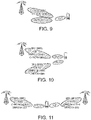
- FIG. 9 illustrates a fourth co-location type, according to certain embodiments.
- co-location Type B3 can indicate that BRS, BRRS, DMRS for control demodulation, and DMRS for data demodulation are grouped according to same UE beamforming Rx1.
- the DMRS for data demodulation may not be using the same co-location assumptions for delay spread, Doppler spread, Doppler shift, and average delay.
- FIG 10 illustrates a fifth co-location type, according to certain embodiments.
- co-location Type C1 can permit different BRS beams or different transmission points, while groups of transmitted signals can use the same UE beamforming processing.
- FIG 11 illustrates a sixth co-location type, according to certain embodiments.
- co-location Type C2 can permit different BRS or different point transmission, indicating that groups of transmitted signals are using the same UE beamforming processing.
- co-location types can be created with isotropic assumption in the UE receiver and also with non-isotropic assumption as mentioned below, three or more bits being used for this configuration.
- Types A through C can be defined as set forth below and indicated with two bits, with isotropic UE receiver and isotropic UE receiver being a further option indicated in a third bit.
- type A BRS in type A BRS, BRRS, DMRS for control demodulation, and DMRS for data demodulation are collocated with respect to delay spread, Doppler spread, Doppler shift, and average delay.
- type B BRS, BRRS, and DMRS for control demodulation are collocated with respect to delay spread, Doppler spread, Doppler shift, and average delay.
- Figure 12 illustrates a system according to certain embodiments of the invention. It should be understood that each block of the flowchart of Figure 5 may be implemented by various means or their combinations, such as hardware, software, firmware, one or more processors and/or circuitry.
- a system may include several devices, such as, for example, network element 1210 and user equipment (UE) or user device 1220.
- the system may include more than one UE 1220 and more than one network element 1210, although only one of each is shown for the purposes of illustration.
- a network element can be an access point, a base station, an eNode B (eNB), or any other network element.
- eNB eNode B
- Transceivers 1216 and 1226 may each, independently, be a transmitter, a receiver, or both a transmitter and a receiver, or a unit or device that may be configured both for transmission and reception.
- the transmitter and/or receiver (as far as radio parts are concerned) may also be implemented as a remote radio head which is not located in the device itself, but in a mast, for example.
- the operations and functionalities may be performed in different entities, such as nodes, hosts or servers, in a flexible manner. In other words, division of labor may vary case by case.
- One possible use is to make a network element to deliver local content.
- One or more functionalities may also be implemented as a virtual application that is provided as software that can run on a server.
- a user device or user equipment 1220 may be a mobile station (MS) such as a mobile phone or smart phone or multimedia device, a computer, such as a tablet, provided with wireless communication capabilities, a vehicle, personal data or digital assistant (PDA) provided with wireless communication capabilities, portable media player, digital camera, pocket video camera, navigation unit provided with wireless communication capabilities or any combinations thereof.
- MS mobile station
- PDA personal data or digital assistant
- the user device or user equipment 1220 may be a sensor or smart meter, or other device that may usually be configured for a single location.
- an apparatus such as a node or user device, may include means for carrying out embodiments described above in relation to Figure 5 .
- Processors 1214 and 1224 may be embodied by any computational or data processing device, such as a central processing unit (CPU), digital signal processor (DSP), application specific integrated circuit (ASIC), programmable logic devices (PLDs), field programmable gate arrays (FPGAs), digitally enhanced circuits, or comparable device or a combination thereof.
- the processors may be implemented as a single controller, or a plurality of controllers or processors. Additionally, the processors may be implemented as a pool of processors in a local configuration, in a cloud configuration, or in a combination thereof.
- the implementation may include modules or units of at least one chip set (e.g., procedures, functions, and so on).
- Memories 1215 and 1225 may independently be any suitable storage device, such as a non-transitory computer-readable medium.
- a hard disk drive (HDD), random access memory (RAM), flash memory, or other suitable memory may be used.
- the memories may be combined on a single integrated circuit as the processor, or may be separate therefrom.
- the computer program instructions may be stored in the memory and which may be processed by the processors can be any suitable form of computer program code, for example, a compiled or interpreted computer program written in any suitable programming language.
- the memory or data storage entity is typically internal but may also be external or a combination thereof, such as in the case when additional memory capacity is obtained from a service provider.
- the memory may be fixed or removable.
- a non-transitory computer-readable medium may be encoded with computer instructions or one or more computer program (such as added or updated software routine, applet or macro) that, when executed in hardware, may perform a process such as one of the processes described herein.
- Computer programs may be coded by a programming language, which may be a high-level programming language, such as objective-C, C, C++, C#, Java, etc., or a low-level programming language, such as a machine language, or assembler. Alternatively, certain embodiments of the invention may be performed entirely in hardware.
- Figure 12 illustrates a system including a network element 1210 and a UE 1220
- embodiments of the invention may be applicable to other configurations, and configurations involving additional elements, as illustrated and discussed herein.
- multiple user equipment devices and multiple network elements may be present, or other nodes providing similar functionality, such as nodes that combine the functionality of a user equipment and an access point, such as a relay node.
- a method can include receiving an indication of a set of co-location rules to apply from sets of co-location rules (for example, from at least three sets in certain embodiments). The method can also include applying the indicated set of co-location rules.
- the indication can comprise an implicit indication.
- the indication can comprise an explicit indication.
- the explicit indication can comprise a two-bit indication or a three-bit indication.
- the indication can comprise information regarding whether a receiver of the user equipment is isotropic or non-isotropic.
- the indication can comprise information regarding user equipment beam forming configuration in reception.
- the indication can comprise information regarding which symbols or signals are co-located with one another.
- the indication can be configured to indicate colocation of a plurality of BRS, BRRS, DMRS for control demodulation, DMRS for data demodulation, and RS for automatic gain control.
- a method can include determining a set of co-location rules to apply. The method can also include sending an indication of the determined set of co-location rules to a user equipment.
- an apparatus can include means for performing the method according to the first and second embodiments respectively, in any of their variants.
- an apparatus can include at least one processor and at least one memory and computer program code.
- the at least one memory and the computer program code can be configured to, with the at least one processor, cause the apparatus at least to perform the method according to the first and second embodiments respectively, in any of their variants.
- a system may include at least one apparatus according to the third or fifth embodiments in communication with at least one apparatus according to the fourth or sixth embodiments, respectively in any of their variants.
Landscapes
- Engineering & Computer Science (AREA)
- Signal Processing (AREA)
- Computer Networks & Wireless Communication (AREA)
- Mobile Radio Communication Systems (AREA)
Applications Claiming Priority (3)
| Application Number | Priority Date | Filing Date | Title |
|---|---|---|---|
| US201662334197P | 2016-05-10 | 2016-05-10 | |
| EP17795702.4A EP3456017B1 (fr) | 2016-05-10 | 2017-05-05 | Hypothèses de colocalisation d'antennes et de récepteurs |
| PCT/IB2017/052640 WO2017195082A1 (fr) | 2016-05-10 | 2017-05-05 | Hypothèses de colocalisation d'antennes et de récepteurs |
Related Parent Applications (1)
| Application Number | Title | Priority Date | Filing Date |
|---|---|---|---|
| EP17795702.4A Division EP3456017B1 (fr) | 2016-05-10 | 2017-05-05 | Hypothèses de colocalisation d'antennes et de récepteurs |
Publications (1)
| Publication Number | Publication Date |
|---|---|
| EP4072092A1 true EP4072092A1 (fr) | 2022-10-12 |
Family
ID=60267555
Family Applications (2)
| Application Number | Title | Priority Date | Filing Date |
|---|---|---|---|
| EP22176456.6A Pending EP4072092A1 (fr) | 2016-05-10 | 2017-05-05 | Co-localisation d'antenne et hypothèses de récepteur |
| EP17795702.4A Active EP3456017B1 (fr) | 2016-05-10 | 2017-05-05 | Hypothèses de colocalisation d'antennes et de récepteurs |
Family Applications After (1)
| Application Number | Title | Priority Date | Filing Date |
|---|---|---|---|
| EP17795702.4A Active EP3456017B1 (fr) | 2016-05-10 | 2017-05-05 | Hypothèses de colocalisation d'antennes et de récepteurs |
Country Status (5)
| Country | Link |
|---|---|
| US (1) | US10574331B2 (fr) |
| EP (2) | EP4072092A1 (fr) |
| KR (1) | KR102175418B1 (fr) |
| CN (2) | CN113746521A (fr) |
| WO (1) | WO2017195082A1 (fr) |
Families Citing this family (9)
| Publication number | Priority date | Publication date | Assignee | Title |
|---|---|---|---|---|
| US10797771B2 (en) * | 2015-10-26 | 2020-10-06 | Apple Inc. | Reference signal for receive beam refinement in cellular systems |
| US11038557B2 (en) * | 2016-03-31 | 2021-06-15 | Samsung Electronics Co., Ltd. | Method and apparatus for transmitting and receiving reference signals in wireless communication |
| US10834716B2 (en) * | 2016-07-28 | 2020-11-10 | Lg Electronics Inc. | Method for receiving reference signal in wireless communication system and device therefor |
| AU2017304162A1 (en) * | 2016-07-28 | 2019-02-07 | Lg Electronics Inc. | Method for receiving reference signal in wireless communication system and device therefor |
| EP3520242A4 (fr) * | 2016-09-30 | 2020-05-06 | Nokia Technologies Oy | Détermination, par un noeud d'accès, d'une association entre un indice de faisceau d'affinement (bl) et un bl logique |
| US10686506B2 (en) | 2017-08-04 | 2020-06-16 | Qualcomm Incorporated | Subset based spatial quasi-colocation parameter indication using multiple beams |
| US11057917B2 (en) * | 2018-11-12 | 2021-07-06 | Qualcomm Incorporated | Quasi co-location relation configuration for periodic channel state information reference signals |
| CN111435883B (zh) * | 2019-01-11 | 2021-10-26 | 华为技术有限公司 | 准共址指示方法及装置 |
| WO2020186440A1 (fr) * | 2019-03-19 | 2020-09-24 | Qualcomm Incorporated | Commande de gain automatique de récepteur |
Family Cites Families (77)
| Publication number | Priority date | Publication date | Assignee | Title |
|---|---|---|---|---|
| US6349208B1 (en) * | 1999-04-28 | 2002-02-19 | Nokia Corporation | Apparatus and associated method for selectively permitting initiation or cell reselection in a radio communication system |
| FI20002867A (fi) * | 2000-12-28 | 2002-06-29 | Nokia Corp | Toimialueen valitseminen sijaintipalvelupyynnön välittämiseksi |
| US6785259B2 (en) * | 2001-11-16 | 2004-08-31 | Nokia Corporation | Enhanced transmission of critical data |
| US20030147539A1 (en) * | 2002-01-11 | 2003-08-07 | Mh Acoustics, Llc, A Delaware Corporation | Audio system based on at least second-order eigenbeams |
| US20040255302A1 (en) * | 2003-06-10 | 2004-12-16 | Nokia Corporation | Systems and methods for content and service registration, query and subscription, and notification across local service discovery domains |
| US20050071510A1 (en) * | 2003-09-29 | 2005-03-31 | Nokia Corporation | Transport layer communication |
| US8443108B2 (en) * | 2004-06-23 | 2013-05-14 | Nokia Corportion | Centrally controlled backup functionality |
| US7821875B2 (en) * | 2004-07-01 | 2010-10-26 | Nokia Corporation | Daylight saving time support for mobile devices |
| US20060212836A1 (en) * | 2005-03-15 | 2006-09-21 | Nokia Corporation | Personalized user interfaces for presentation-oriented web services |
| US20060246881A1 (en) * | 2005-04-28 | 2006-11-02 | Nokia Corporation | Call control system and method for targeting calls |
| US7765184B2 (en) * | 2005-09-22 | 2010-07-27 | Nokia Corporation | Metadata triggered notification for content searching |
| US7599714B2 (en) * | 2005-09-30 | 2009-10-06 | Alcatel-Lucent Usa Inc. | Increasing the range of access point cells for a given throughput in a downlink of a wireless local area network |
| US20070260780A1 (en) * | 2006-04-11 | 2007-11-08 | Nokia Corporation | Media subsystem, method and computer program product for adaptive media buffering |
| US20100330940A1 (en) * | 2006-10-31 | 2010-12-30 | Qualcomm Incorporated | Sensor-aided wireless combining |
| US8428583B2 (en) * | 2006-12-21 | 2013-04-23 | Nokia Corporation | Managing subscriber information |
| US20100153568A1 (en) * | 2008-12-16 | 2010-06-17 | Nokia Corporation | Methods, apparatuses, and computer program products for providing a local proxy for accessing web services |
| US9264111B2 (en) * | 2009-10-05 | 2016-02-16 | Simon Fraser University | Reassignment of data among subcarriers in wireless data communication |
| US8995931B2 (en) * | 2010-01-27 | 2015-03-31 | Broadcom Corporation | Creating a system on the fly and applications thereof |
| US8544103B2 (en) * | 2010-05-04 | 2013-09-24 | Intertrust Technologies Corporation | Policy determined accuracy of transmitted information |
| US8995465B2 (en) * | 2010-05-04 | 2015-03-31 | Qualcomm Incorporated | Reference signal patterns |
| WO2012017132A1 (fr) * | 2010-08-06 | 2012-02-09 | Nokia Corporation | Alarmes lancées par le réseau pour des dispositifs utilisant une connexion locale |
| US20140050113A1 (en) * | 2011-04-29 | 2014-02-20 | Nokia Siemens Networks Oy | Method and Apparatus for Deactivating One of a Primary and Secondary Cells of a User Equipment |
| US9642161B2 (en) * | 2011-05-11 | 2017-05-02 | Nokia Solutions And Networks Oy | Cross-scheduling for random access response |
| US9509377B2 (en) * | 2011-11-07 | 2016-11-29 | Google Technology Holdings LLC | Method and apparatus for rank adaptation in an orthogonal frequency division multiplexing communication system |
| ES2669571T3 (es) * | 2011-12-27 | 2018-05-28 | Intel Corporation | Método y sistema para la coexistencia de múltiples radios coubicadas |
| US8964632B2 (en) * | 2012-02-03 | 2015-02-24 | Telefonaktiebolaget L M Ericsson (Publ) | Methods and arrangements for channel estimation |
| CN104106223A (zh) * | 2012-02-11 | 2014-10-15 | Lg电子株式会社 | 报告信道状态信息的方法、其支持方法及所述方法的设备 |
| US9294924B2 (en) * | 2012-04-13 | 2016-03-22 | Nokia Solutions And Networks Oy | Monitoring suspicious events in a cellular network |
| CA2865770C (fr) * | 2012-04-19 | 2020-12-01 | Samsung Electronics Co., Ltd. | Procede et appareil pour l'identification de ports de symboles de reference presque colocalises dans les systemes de communication multipoint coordonnee |
| US10146956B2 (en) * | 2012-05-07 | 2018-12-04 | Nokia Technologies Oy | Method and apparatus for providing location privacy |
| US8982693B2 (en) * | 2012-05-14 | 2015-03-17 | Google Technology Holdings LLC | Radio link monitoring in a wireless communication device |
| US9198070B2 (en) * | 2012-05-14 | 2015-11-24 | Google Technology Holdings LLC | Radio link monitoring in a wireless communication device |
| US20130332279A1 (en) * | 2012-06-07 | 2013-12-12 | Nokia Corporation | Method and apparatus for location-based advertisements for dynamic points of interest |
| WO2014009603A1 (fr) * | 2012-07-02 | 2014-01-16 | Nokia Corporation | Procédé et appareil de codage vidéo |
| US20140045510A1 (en) * | 2012-07-25 | 2014-02-13 | Nec Laboratories America, Inc. | Coordinated Multipoint Transmission and Reception (CoMP) |
| US9306640B2 (en) * | 2012-09-07 | 2016-04-05 | Qualcomm Incorporated | Selecting a modulation and coding scheme for beamformed communication |
| CN104641582B (zh) * | 2012-09-16 | 2018-03-16 | Lg 电子株式会社 | 在无线通信系统中考虑天线端口关系发送/接收下行链路信号的方法和装置 |
| KR102148651B1 (ko) * | 2012-09-21 | 2020-08-27 | 엘지전자 주식회사 | 무선 통신 시스템에서 하향링크 신호를 송수신하는 방법 및 이를 위한 장치 |
| US9769807B2 (en) * | 2012-09-28 | 2017-09-19 | Telefonaktiebolaget Lm Ericsson (Publ) | User equipment, radio network node and methods therein |
| EP2912832A1 (fr) * | 2012-10-29 | 2015-09-02 | Nokia Solutions and Networks Oy | Localisation d'utilisateur lors de l'accès à un réseau 3gpp par l'intermédiaire d'un réseau fixe |
| US9521664B2 (en) * | 2012-11-02 | 2016-12-13 | Qualcomm Incorporated | EPDCCH resource and quasi-co-location management in LTE |
| US20150278298A1 (en) * | 2012-11-06 | 2015-10-01 | Nokia Corporation | Apparatus and method for displaying image-based representations of geographical locations in an electronic text |
| GB2512268B (en) * | 2012-12-03 | 2015-02-18 | Broadcom Corp | Interference cancellation |
| US9160064B2 (en) * | 2012-12-28 | 2015-10-13 | Kopin Corporation | Spatially diverse antennas for a headset computer |
| CN105144612B (zh) * | 2013-02-21 | 2018-03-23 | Lg 电子株式会社 | 在无线通信系统中对于大规模mimo在天线端口之间配置qcl的方法和设备 |
| US9197962B2 (en) * | 2013-03-15 | 2015-11-24 | Mh Acoustics Llc | Polyhedral audio system based on at least second-order eigenbeams |
| GB2512599B (en) * | 2013-04-02 | 2015-10-14 | Broadcom Corp | Joint scheduling in a coordinated multipoint system |
| GB2512653B (en) * | 2013-04-05 | 2018-04-11 | Broadcom Corp | Interference mitigation |
| US9930363B2 (en) * | 2013-04-12 | 2018-03-27 | Nokia Technologies Oy | Harmonized inter-view and view synthesis prediction for 3D video coding |
| US20140324527A1 (en) * | 2013-04-25 | 2014-10-30 | Readme Systems, Inc. | Proximity detection using sensors based on a programmable multi-array structures |
| US20140348273A1 (en) * | 2013-05-22 | 2014-11-27 | Nokia Siemens Networks Oy | Offset estimation using channel state information reference symbols and demodulation reference symbols |
| PT3462798T (pt) * | 2014-03-25 | 2021-11-25 | Ericsson Telefon Ab L M | Sistema e método para acesso aleatório físico baseado em feixe |
| US10666338B2 (en) * | 2014-05-30 | 2020-05-26 | Lg Electronics Inc. | Channel quality measurement method in multiple antenna wireless communication system and device for same |
| US20150365178A1 (en) * | 2014-06-12 | 2015-12-17 | Broadcom Corporation | System, method, and apparatus for signaling intefering cell information |
| WO2016043839A1 (fr) * | 2014-09-15 | 2016-03-24 | Nokia Solutions And Networks Oy | Distribution d'analyses de réseau cellulaire à des dispositifs d'abonnés au moyen d'un ssid par l'intermédiaire d'un bloc d'informations de système cellulaire |
| EP3057373B1 (fr) * | 2015-02-12 | 2021-12-01 | Nokia Technologies Oy | Transmission point à multipoint à cellule unique |
| CN108141884B (zh) * | 2015-07-16 | 2021-07-20 | Zte维创通讯公司 | 基于测量的随机接入配置 |
| WO2017026794A1 (fr) * | 2015-08-13 | 2017-02-16 | 엘지전자(주) | Procédé de fonctionnement de terminal en association avec un signal csi-rs dans un système de communication sans fil, et appareil de prise en charge associé |
| US10797771B2 (en) * | 2015-10-26 | 2020-10-06 | Apple Inc. | Reference signal for receive beam refinement in cellular systems |
| US11096169B2 (en) * | 2015-11-18 | 2021-08-17 | Nokia Solutions And Networks Oy | Use of mapping options for logical channels and transport channels for wireless networks |
| US10720973B2 (en) * | 2016-02-04 | 2020-07-21 | Kt Corporation | Method for ultra-high frequency mobile communication system transreceiving reference signal and feedback and apparatus for same |
| US11038557B2 (en) * | 2016-03-31 | 2021-06-15 | Samsung Electronics Co., Ltd. | Method and apparatus for transmitting and receiving reference signals in wireless communication |
| US10141986B2 (en) * | 2016-04-14 | 2018-11-27 | Samsung Electronics Co., Ltd. | Method and apparatus for transmitting and receiving signal through beamforming in communication system |
| GB2551476A (en) * | 2016-05-11 | 2017-12-27 | Nokia Solutions & Networks Oy | Method, system and apparatus |
| US10367677B2 (en) * | 2016-05-13 | 2019-07-30 | Telefonaktiebolaget Lm Ericsson (Publ) | Network architecture, methods, and devices for a wireless communications network |
| US10630410B2 (en) * | 2016-05-13 | 2020-04-21 | Telefonaktiebolaget Lm Ericsson (Publ) | Network architecture, methods, and devices for a wireless communications network |
| US10892815B2 (en) * | 2016-08-22 | 2021-01-12 | Telefonaktiebolaget Lm Ericsson (Publ) | EVM requirements for wireless communication |
| EP3345312A1 (fr) * | 2016-09-30 | 2018-07-11 | Telefonaktiebolaget LM Ericsson (PUBL) | Quasi colocalisation pour formation de faisceau |
| US10582504B2 (en) * | 2017-02-23 | 2020-03-03 | Qualcomm Incorporated | Usage of synchronization signal block index in new radio |
| US10779259B2 (en) * | 2017-04-03 | 2020-09-15 | Qualcomm Incorporated | Quasi co-location of antenna ports used to transmit paging message and synchronization signals |
| US10979186B2 (en) * | 2017-05-01 | 2021-04-13 | Lg Electronics Inc. | Method of sounding a terminal in a wireless communication system and apparatus therefor |
| RU2762242C2 (ru) * | 2017-05-04 | 2021-12-16 | ЭлДжи ЭЛЕКТРОНИКС ИНК. | Способ и устройство для передачи и приема восходящей линии связи в системе беспроводной связи |
| US10666400B2 (en) * | 2017-09-11 | 2020-05-26 | Nokia Technologies Oy | Enhancing monitoring of multiple physical downlink control channels in beam based system |
| US10880761B2 (en) * | 2017-09-11 | 2020-12-29 | Qualcomm Incorporated | System and method for selecting resources to transmit a beam failure recovery request |
| US10701671B2 (en) * | 2017-10-31 | 2020-06-30 | Qualcomm Incorporated | Overhead reduction in millimeter wave systems |
| US10419162B2 (en) * | 2017-11-27 | 2019-09-17 | Nokia Technologies Oy | Dynamic scheduling based QCL association for tracking reference signal |
| CN110945822B (zh) * | 2017-12-01 | 2022-08-02 | Lg 电子株式会社 | 在无线通信系统中的上行链路发送和接收方法及其装置 |
-
2017
- 2017-05-05 US US16/300,508 patent/US10574331B2/en active Active
- 2017-05-05 CN CN202111010128.2A patent/CN113746521A/zh active Pending
- 2017-05-05 EP EP22176456.6A patent/EP4072092A1/fr active Pending
- 2017-05-05 KR KR1020187035523A patent/KR102175418B1/ko active IP Right Grant
- 2017-05-05 CN CN201780042384.5A patent/CN109479042B/zh active Active
- 2017-05-05 WO PCT/IB2017/052640 patent/WO2017195082A1/fr unknown
- 2017-05-05 EP EP17795702.4A patent/EP3456017B1/fr active Active
Non-Patent Citations (4)
| Title |
|---|
| 3GPP DOCUMENT RL-162895 |
| 3GPP TS 36.213 |
| HUAWEI ET AL: "Discussion on impact of geographically separated antenna deployment for non-TM10 UE", vol. RAN WG4, no. St Julian; 20130128 - 20130201, 21 January 2013 (2013-01-21), XP050674920, Retrieved from the Internet <URL:http://www.3gpp.org/ftp/tsg_ran/WG4_Radio/TSGR4_66/Docs/> [retrieved on 20130121] * |
| ZTE: "Quasi Co-Location of Antenna Ports for FD-MIMO", vol. RAN WG1, no. Anaheim, USA; 20151115 - 20151122, 15 November 2015 (2015-11-15), XP051003184, Retrieved from the Internet <URL:http://www.3gpp.org/ftp/Meetings_3GPP_SYNC/RAN1/Docs/> [retrieved on 20151115] * |
Also Published As
| Publication number | Publication date |
|---|---|
| KR102175418B1 (ko) | 2020-11-09 |
| WO2017195082A1 (fr) | 2017-11-16 |
| US10574331B2 (en) | 2020-02-25 |
| EP3456017A4 (fr) | 2020-01-15 |
| CN113746521A (zh) | 2021-12-03 |
| US20190238211A1 (en) | 2019-08-01 |
| EP3456017B1 (fr) | 2022-06-01 |
| EP3456017A1 (fr) | 2019-03-20 |
| CN109479042A (zh) | 2019-03-15 |
| KR20190005947A (ko) | 2019-01-16 |
| CN109479042B (zh) | 2021-10-08 |
Similar Documents
| Publication | Publication Date | Title |
|---|---|---|
| EP3456017B1 (fr) | Hypothèses de colocalisation d'antennes et de récepteurs | |
| EP3455948B1 (fr) | Procédé, système et appareil de sélection de faisceau | |
| CN111213417B (zh) | 增强的探测参考信号传输 | |
| CN108702277B (zh) | 上行链路控制信息的通信 | |
| CN109644025B (zh) | 具有波束赋形训练和信道估计的参考信号 | |
| KR20190101449A (ko) | 다중 입력 다중 출력 무선 시스템을 위한 사운딩 기준 신호 전력 제어 | |
| CN108702276B (zh) | 上行链路控制信息的通信 | |
| JP2013524646A (ja) | ノンサービングセルに対するセル固有参照シンボルローケーションでの物理的ダウンリンク共用チャネルミュート | |
| CN109565855A (zh) | 上行传输的方法、终端设备和网络设备 | |
| CN110224796B (zh) | 上行控制信息的发送、接收方法和装置 | |
| US11152996B2 (en) | Refinement beam index beam identifier association | |
| CN112333125B (zh) | 信号处理的方法和装置 | |
| CN112543443A (zh) | 通信方法和通信装置 | |
| CN110351058B (zh) | 一种信号传输方法及通信设备 | |
| CN111446995A (zh) | 一种用于多天线传输的用户设备、基站中的方法和装置 | |
| CN110620642B (zh) | 分配时频资源的方法和装置 | |
| US11184127B2 (en) | Reference signal patterns | |
| CN110493881B (zh) | 一种ue、基站中的用于多天线传输方法和装置 | |
| CN118102463A (zh) | 信息传输方法、装置及系统 | |
| CN117413596A (zh) | 动态切换指示的方法 | |
| CN117955596A (zh) | 信道状态信息的发送、接收方法、装置及存储介质 | |
| WO2017163276A1 (fr) | Station de base radio, système de radiocommunication, et procédé de planification de radiocommunication |
Legal Events
| Date | Code | Title | Description |
|---|---|---|---|
| PUAI | Public reference made under article 153(3) epc to a published international application that has entered the european phase |
Free format text: ORIGINAL CODE: 0009012 |
|
| STAA | Information on the status of an ep patent application or granted ep patent |
Free format text: STATUS: THE APPLICATION HAS BEEN PUBLISHED |
|
| AC | Divisional application: reference to earlier application |
Ref document number: 3456017 Country of ref document: EP Kind code of ref document: P |
|
| AK | Designated contracting states |
Kind code of ref document: A1 Designated state(s): AL AT BE BG CH CY CZ DE DK EE ES FI FR GB GR HR HU IE IS IT LI LT LU LV MC MK MT NL NO PL PT RO RS SE SI SK SM TR |
|
| STAA | Information on the status of an ep patent application or granted ep patent |
Free format text: STATUS: REQUEST FOR EXAMINATION WAS MADE |
|
| 17P | Request for examination filed |
Effective date: 20230412 |
|
| RBV | Designated contracting states (corrected) |
Designated state(s): AL AT BE BG CH CY CZ DE DK EE ES FI FR GB GR HR HU IE IS IT LI LT LU LV MC MK MT NL NO PL PT RO RS SE SI SK SM TR |