EP4072054B1 - Uplink channel transmission method, terminal, and base station - Google Patents
Uplink channel transmission method, terminal, and base station Download PDFInfo
- Publication number
- EP4072054B1 EP4072054B1 EP20897577.1A EP20897577A EP4072054B1 EP 4072054 B1 EP4072054 B1 EP 4072054B1 EP 20897577 A EP20897577 A EP 20897577A EP 4072054 B1 EP4072054 B1 EP 4072054B1
- Authority
- EP
- European Patent Office
- Prior art keywords
- symbol
- uplink channels
- transmission
- channel
- channels
- Prior art date
- Legal status (The legal status is an assumption and is not a legal conclusion. Google has not performed a legal analysis and makes no representation as to the accuracy of the status listed.)
- Active
Links
Images


Classifications
-
- H—ELECTRICITY
- H04—ELECTRIC COMMUNICATION TECHNIQUE
- H04L—TRANSMISSION OF DIGITAL INFORMATION, e.g. TELEGRAPHIC COMMUNICATION
- H04L5/00—Arrangements affording multiple use of the transmission path
- H04L5/0001—Arrangements for dividing the transmission path
- H04L5/0003—Two-dimensional division
- H04L5/0005—Time-frequency
- H04L5/0007—Time-frequency the frequencies being orthogonal, e.g. OFDM(A) or DMT
- H04L5/0008—Wavelet-division
-
- H—ELECTRICITY
- H04—ELECTRIC COMMUNICATION TECHNIQUE
- H04W—WIRELESS COMMUNICATION NETWORKS
- H04W72/00—Local resource management
- H04W72/12—Wireless traffic scheduling
- H04W72/1263—Mapping of traffic onto schedule, e.g. scheduled allocation or multiplexing of flows
- H04W72/1268—Mapping of traffic onto schedule, e.g. scheduled allocation or multiplexing of flows of uplink data flows
-
- H—ELECTRICITY
- H04—ELECTRIC COMMUNICATION TECHNIQUE
- H04L—TRANSMISSION OF DIGITAL INFORMATION, e.g. TELEGRAPHIC COMMUNICATION
- H04L5/00—Arrangements affording multiple use of the transmission path
- H04L5/003—Arrangements for allocating sub-channels of the transmission path
- H04L5/0044—Allocation of payload; Allocation of data channels, e.g. PDSCH or PUSCH
-
- H—ELECTRICITY
- H04—ELECTRIC COMMUNICATION TECHNIQUE
- H04L—TRANSMISSION OF DIGITAL INFORMATION, e.g. TELEGRAPHIC COMMUNICATION
- H04L5/00—Arrangements affording multiple use of the transmission path
- H04L5/003—Arrangements for allocating sub-channels of the transmission path
- H04L5/0053—Allocation of signalling, i.e. of overhead other than pilot signals
- H04L5/0055—Physical resource allocation for ACK/NACK
-
- H—ELECTRICITY
- H04—ELECTRIC COMMUNICATION TECHNIQUE
- H04L—TRANSMISSION OF DIGITAL INFORMATION, e.g. TELEGRAPHIC COMMUNICATION
- H04L5/00—Arrangements affording multiple use of the transmission path
- H04L5/0091—Signalling for the administration of the divided path, e.g. signalling of configuration information
- H04L5/0094—Indication of how sub-channels of the path are allocated
-
- H—ELECTRICITY
- H04—ELECTRIC COMMUNICATION TECHNIQUE
- H04W—WIRELESS COMMUNICATION NETWORKS
- H04W72/00—Local resource management
- H04W72/20—Control channels or signalling for resource management
-
- H—ELECTRICITY
- H04—ELECTRIC COMMUNICATION TECHNIQUE
- H04L—TRANSMISSION OF DIGITAL INFORMATION, e.g. TELEGRAPHIC COMMUNICATION
- H04L5/00—Arrangements affording multiple use of the transmission path
- H04L5/0001—Arrangements for dividing the transmission path
- H04L5/0003—Two-dimensional division
- H04L5/0005—Time-frequency
-
- H—ELECTRICITY
- H04—ELECTRIC COMMUNICATION TECHNIQUE
- H04W—WIRELESS COMMUNICATION NETWORKS
- H04W28/00—Network traffic management; Network resource management
- H04W28/02—Traffic management, e.g. flow control or congestion control
- H04W28/0252—Traffic management, e.g. flow control or congestion control per individual bearer or channel
-
- H—ELECTRICITY
- H04—ELECTRIC COMMUNICATION TECHNIQUE
- H04W—WIRELESS COMMUNICATION NETWORKS
- H04W72/00—Local resource management
- H04W72/20—Control channels or signalling for resource management
- H04W72/23—Control channels or signalling for resource management in the downlink direction of a wireless link, i.e. towards a terminal
Definitions
- the present application relates to the technical field of communication, and in particular, to a method for uplink channel transmission, a terminal, and a base station.
- PUCCH Physical Uplink Control Channel
- PUSCH Physical Uplink Shared Channel
- UCI uplink control information
- HARQ-ACK hybrid automatic repeat request-acknowledge character
- CSI channel state information
- SR scheduling request
- a PUSCH may be selected from the multiple PUSCHs according to a predetermined rule, for example, the PUSCH carrying aperiodic channel state information (A-CSI) (if any) is preferentially selected.
- A-CSI aperiodic channel state information
- a PUSCH with a corresponding physical downlink control channel is preferentially selected.
- PUSCHs of the same type for example, PUSCHs with corresponding PDCCHs, or PUSCHs without corresponding PDCCHs if there is no PUSCH with a corresponding PDCCH
- the PUSCH on a carrier having the smallest carrier number is selected, and the PUSCH earliest in time is selected when there are multiple overlapped PUSCHs and PUCCHs on the selected carrier.
- the PUCCHs carrying the UCI overlap in time domain, it is also required to determine whether the first symbol of the earliest initial channel in the overlapped PUCCHs satisfies the predefined timeline.
- the predefined timeline is satisfied, the UCIs on a plurality of PUCCHs can be transmitted in combination in a PUCCH channel, thereby avoiding parallel transmissions of the plurality of PUCCHs. It is defined in R15 that there is no case where the timeline is not satisfied, that is, the case where the timeline is not satisfied is an incorrect scheduling and no cation is performed.
- scheduling and configurations are performed in the respective base stations, it is required to ensure that the overlapped channels always satisfy the timeline.
- US2017135090A1 discloses a user equipment (UE) for reporting uplink control information (UCI) when one or more Licensed-Assisted Access (LAA) serving cells are configured.
- the UE includes a processor and memory in electronic communication with the processor. Instructions stored in the memory are executable to determine if physical uplink shared channel (PUSCH) transmissions are scheduled on LAA serving cells and licensed cells. The instructions are also executable to determine a type of UCI to be reported. The instructions are further executable to determine a channel and cells to carry different UCI. The instructions are additionally executable to transmit the channel on the cells determined to carry UCI. The instructions are also executable to determine whether a LAA PUSCH is transmitted and UCI is multiplexed. The instructions are further executable to drop LAA PUSCH or transmit LAA PUSCH subject to listen-before-talk (LBT).
- LBT listen-before-talk
- KR20170112633A discloses a method and apparatus for multiplexing transmission of an uplink control channel and transmission of a sounding reference signal in an unlicensed spectrum of a wireless communication system.
- EP2660992A1 discloses a method and a device for transmitting data.
- the method includes: a UE determining, according to a preset rule, whether to transmit PUCCH data and/or PUSCH data and/or an SRS or not on a last symbol of a current subframe; the UE determining the PUCCH data and/or the PUSCH data to be transmitted on the current subframe according to availability of the last symbol of the current subframe for transmitting the PUCCH data and/or the PUSCH data; and the UE transmitting the PUCCH data and/or the PUSCH data on the current subframe and/or transmitting the SRS on the last symbol of the current subframe.
- US20190261391A1 discloses an apparatus of a user equipment (UE) to operate in a New Radio (NR) system, which comprises one or more baseband processors to determine if two or more uplink signals partially overlap, determine a multiplexing rule, a dropping rule, or a priority rule for the two or more uplink signals, and to multiplex, drop, or prioritize the two or more uplink signals for transmission according to the multiplexing rule, dropping rule, or priority rule, and a memory to store two or more uplink signals.
- NR New Radio
- Embodiments of the present application provide a method for uplink channel transmission, a terminal, and a base station, for ensuring normal transmission of a system when the uplink channels overlap and improving transmission performance of the system.
- the invention is limited by the appended set of independent claims. Further embodiments are defined by the dependent claims.
- the PUCCH carrying HARQ-ACK uses PUCCH format 0, and the PUCCH carrying SR can use either format 0 or format 1, the SR and HARQ-ACK are multiplexed and transmitted on the PUCCH resource of HARQ-ACK. That is, the HARQ-ACK is transmitted on the PUCCH resource of the HARQ-ACK by selecting a cyclic shift (CS) corresponding to the HARQ-ACK depend on whether a positive SR or a negative SR exists, which is implicitly indicated as positive or negative.
- CS cyclic shift
- the PUCCH carrying SR uses format 1 and the PUCCH carrying HARQ-ACK uses format 1, HARQ-ACK is transmitted on the PUCCH resource of SR when SR is a positive, such that the simultaneous transmission of SR is implicitly indicated by transmitting HARQ-ACK using the PUCCH resource corresponding to SR, otherwise (i.e., negative SR), the HARQ-ACK is transmitted on the PUCCH resource of the HARQ-ACK.
- a set of PUCCH resources is determined according to the total number of bits of the SR and HARQ-ACK.
- DCI Downlink Control Information
- a PUCCH resource is determined from the determined set of PUCCH resources for simultaneously transmitting the SR and HARQ -ACK, wherein SR is X bits, indicating SR status of X SRs overlapping with the HARQ-ACK (which one is positive, or both are negative). That is, whether SR is positive or negative, X-bit SR is always transmitted, so as to avoid change of the number of bits of UCI transmitted on the PUCCH resource of the HARQ-ACK due to the SR state.
- DCI Downlink Control Information
- SPS semi-persistent scheduling
- PDCCH carrying HARQ-ACK with a corresponding PDCCH that is, when the HARQ-ACK is feedback information of PDSCH, the PDCCH that schedules the PDSCH corresponds to the HARQ-ACK, and when the HARQ-ACK is feedback information of the PDCCH indicating release of downlink SPS resources, the PDCCH corresponds to the HARQ-ACK
- a set of PUCCH resources is selected from a plurality of sets of PUCCH resources according to the total number of bits of the SR and HARQ-ACK; and a PUCCH resource is determined from the selected set of PUCCH resources for simultaneously carrying the HARQ-ACK and CSI, according to a PUCCH resource indication field in DCI corresponding to the HARQ-ACK.
- the re-determined PUCCH resource may be the same as or different from the original PUCCH resource carrying the HARQ-ACK (if different, it is a new PUCCH resource). It is not expected that the terminal is configured to support simultaneous transmission of the HARQ-ACK and CSI when only one set of PUCCH resources is configured.
- the PUCCHs in a time slot constitute a set Q
- an uplink channel in the set Q which starts earliest is determined as channel A
- a set X of channels that overlap with channel A is determined.
- Above-mentioned multiplexing transmission rules are applied to UCI on channel A and channel X to obtain a channel resource for multiplexing transmission, and channel A in the set Q and channel X are replaced with the channel resource for multiplexing transmission.
- the above steps are repeated to determine channel A and channel X in a new set Q and so on, until a plurality of PUCCHs that do not overlap in time domain are obtained.
- the HARQ-ACK carried on the PUCCH is a HARQ-ACK of the PDSCH scheduled by DCI or is an DCI indicating release of a downlink SPS resource
- the DCI scheduling PDSCH or the DCI indicating the release of downlink SPS resource is the DCI corresponding to the PUCCH
- the DCI scheduling the PUSCH is the DCI corresponding to the PUSCH
- the first symbol of the channel among the overlapped channels that starts earliest needs to meet the following timelines.
- Timeline1 the first symbol is not earlier than a symbol including a cyclic prefix (CP) starting later T1 time after the last symbol of any PDSCH or SPS PDSCH release that requires HARQ-ACK feedback on PUCCH, that is, a time interval between the first symbol and the last symbol of any of the above PDSCH or SPS PDSCH release is not less than T1 time.
- T1 is related to a processing delay of PDSCH or SPS PDSCH release and can be calculated according to the formula and related parameters.
- the timeline is intended to ensure that the acquisition and preparation of the HARQ-ACK can be completed before the transmission of the finally determined channel for transmitting the HARQ-ACK starts.
- Timeline2 the first symbol is not earlier than a symbol including a CP starting later T2 time after the last symbol of any PDCCH (including the PDCCH indicating SPS PDSCH release) scheduling PDSCH (if any) and PUSCH (if any), that is, a time interval between the first symbol and the last symbol of any of above PDCCHs is not less than T2 time.
- T2 is related to the processing delay of PUSCH and can be calculated according to the formula and related parameters.
- the timeline is intended to ensure that when there are a plurality of UCI multiplexing transmissions, the acquisition and multiplexing processing of the various UCIs can be completed before the transmission of the target channel for transmitting the UCI starts.
- FIGS. 1-1 to 1-4 that is, FIG. 1-1, FIG. 1-2, FIG. 1-3 , and FIG. 1-4
- a PDCCH scheduling PDSCH DL DCI in the figures
- a PDCCH scheduling PUSCH UL DCI in the figures.
- the HARQ-ACK carried on the PUCCH has no corresponding DCI (that is, the HARQ-ACK is the HARQ-ACK of the SPS PDSCH), in which case there is no DL DCI in the FIGS. 1-1 and 1-2 , and if the PUSCH also has no corresponding DCI, in which case there is no DL DCI in the FIGS. 1-1 and 1-2 , only T1 needs to be checked and T2 does not need to be checked. If the PUCCH overlaps with the PUSCH and the PUCCH carries CSI and/or SR, T1 does not need to be checked, and further, if the PUSCH has no corresponding DCI, T2 does not need to be checked.
- CSI may include aperiodic CSI (A-CSI), semi-persistent CSI (SP-CSI), periodic CSI (P-CSI), which have the priorities of A-CSI, SP-CSI CSI, P-CSI from high to low.
- A-CSI aperiodic CSI
- SP-CSI semi-persistent CSI
- P-CSI periodic CSI
- the terminal side may perform uplink channel transmission through any one of the following two processing modes.
- Mode 1 includes the following steps: step 201: firstly processing the plurality of uplink channels based on a multiplexing rule to determine one or more first target uplink channels to be transmitted, and then determining whether to transmit the one or more first target uplink channels.
- an order of processes for processing the plurality of uplink channels based on the multiplexing rule and for determining whether to transmit the uplink channels is clearly defined, such that the terminal can directly determine the transmission status of the uplink channels according to the order, thereby ensuring the normal transmission of a system.
- Mode 2 includes the following steps: step 301: firstly determining, from the plurality of uplink channels, candidate uplink channels which could be transmitted, and then processing the candidate uplink channels based on a multiplexing rule to determine one or more second target uplink channels to be transmitted.
- this mode specifically, by firstly determining, from the plurality of uplink channels, candidate uplink channels which could be transmitted and then processing the candidate uplink channels based on a multiplexing rule to determine the one or more second target uplink channels to be transmitted, an order of processes for determining whether to transmit the uplink channel and for processing the plurality of uplink channels based on the multiplexing rules is clearly determined, such that a terminal can directly determine the transmission status of the uplink channels according to the order, thereby ensuring the normal transmission of a system.
- the terminal can clearly determine a transmission status of the uplink channels based on the determined order of the processes for determining whether to transmit the uplink channel and for processing the plurality of uplink channels based on the multiplexing rule, thereby ensuring the normal transmission of a system and improving the transmission performance
- Mode 1 when determining whether to transmit the first target uplink channels, it may be checked whether the symbol set in which transmission of the one or more first target uplink channels is located includes a first unavailable symbol. When the symbol set in which the one or more first target uplink channels is located does not include the first unavailable symbol, it is determined to transmit the one or more first target uplink channels.
- the symbol set in which the one or more first target uplink channels is located includes a first unavailable symbol, it is determined not to transmit the one or more first target uplink channels.
- the first unavailable symbol may include at least one of the following symbols: a downlink (DL) symbol configured by a higher layer signaling, a flexible (FL) symbol configured by a higher layer signaling, a symbol scheduled by DCI for downlink transmission, a symbol indicated as DL or FL by indication information in DCI for indicating a structure of a time unit, a symbol for a guard period (referred to as GP), a symbol for a synchronization signal block (referred to as SSB) transmission, an unavailable symbol preconfigured by signaling or a symbol within bandwidth part (referred to as BWP) switching time.
- DL downlink
- FL flexible
- a symbol scheduled by DCI for downlink transmission a symbol indicated as DL or FL by indication information in DCI for indicating a structure of a time unit
- GP symbol for a guard period
- SSB synchronization signal block
- BWP bandwidth part
- the DCI for indicating the structure of the time unit is specifically a DCI for carrying indication information indicating the uplink and downlink structures, for example, DCI format 2-0 scrambled using a slot format indicator-radio network temporary identity (simply referred to as SFI-RNTI).
- the action of DCI scheduling for downlink transmission may include action of instructing the terminal to receive PDSCH or channel state information reference signal (CSI-RS for short) by DCI format 1_0, DCI format 1_1 or DCI format 0_1.
- CSI-RS channel state information reference signal
- the uplink channel when determining, from the plurality of uplink channels, candidate uplink channels which could be transmitted, for each uplink channel of the plurality of uplink channels, it may also be possible to detect whether the symbol set in which the uplink channel is located includes a second unavailable symbol. When the symbol set in which the uplink channel is located does not include the second unavailable symbol, the uplink channel may be determined as a candidate uplink channel. When the symbol set in which the uplink channel is located includes the second unavailable symbol, the uplink channel cannot be determined as a candidate uplink channel.
- the second unavailable symbol may similarly include at least one of the following symbols: a DL symbol configured by a higher layer signaling, a FL symbol configured by a higher layer signaling, a symbol scheduled by DCI for downlink transmission, a symbol indicated as DL or FL by indication information in DCI for indicating a structure of a time unit, a symbol for a GP, a symbol for a SSB transmission, an unavailable symbol preconfigured by signaling or a symbol within BWP switching time.
- the symbol set in which the one or more second target uplink channels is located includes a third unavailable symbol.
- the symbol set in which the second target uplink channel is located does not include a third unavailable symbol, it is determined to transmit the one or more second target uplink channels.
- the symbol set in which the one or more second target uplink channels is located includes the third unavailable symbol, it is determined not to transmit the one or more second target uplink channels.
- the third unavailable symbol may include at least one of the following symbols: a DL symbol configured by a higher layer signaling, a FL symbol configured by a higher layer signaling, a symbol scheduled by DCI for downlink transmission, a symbol indicated as DL or FL by indication information in DCI for indicating a structure of a time unit, a symbol for a GP, a symbol for a SSB transmission, an unavailable symbol preconfigured by signaling or a symbol within BWP switching time.
- first unavailable symbol and the second unavailable symbol may be the same or different from each other, which are not specifically limited here.
- second unavailable symbol and the third unavailable symbol may be the same or different from each other, which is also not specifically limited here.
- the first unavailable symbol may include at least a DL symbol configured by a higher layer signaling, a symbol scheduled by DCI for downlink transmission, a symbol indicated as DL or FL by indication information in DCI for indicating a structure of a time unit, and a symbol for a SSB transmission
- the second unavailable symbol may be the same as the first unavailable symbol or may include at least a DL symbol configured by a higher layer signaling and a symbol for a SSB transmission.
- the third unavailable symbol may include at least a DL symbol configured by a higher layer signaling, a symbol scheduled by DCI for downlink transmission, a symbol indicated as DL or FL by indication information in DCI for indicating a structure of a time unit and a symbol for a SSB transmission.
- the plurality of uplink channels in the present embodiment include at least one channel configured by a higher layer signaling for transmission, that is, a semi-static channel.
- each of the one or more first target uplink channels is a channel configured by a higher layer signaling for transmission, and when each of the first target uplink channels is a channel configured by the higher layer signaling for transmission, it is determined to transmit the one or more first target uplink channels.
- the candidate uplink channels which could be transmitted may be determined from the channels configured by the higher layer signaling for transmission.
- the channel configured by a higher layer signaling for transmission may include at least one of the following channels: a PUSCH without a corresponding PDCCH, a PUCCH transmission using a PUCCH resource corresponding to SPS, a PUCCH transmission using a PUCCH resource corresponding to CSI, or a PUCCH transmission using a PUCCH resource corresponding to a SR.
- the PUSCH not corresponding to the PDCCH may include a cell group PUSCH (referred to as CG PUSCH) and a PUSCH carrying semi-persistent channel state information (referred to as SP-CSI).
- the PUCCH transmitted using the PUCCH resource corresponding to SPS includes a PUCCH carrying HARQ-ACK of the SPS PDSCH.
- the terminal can clearly define a transmission status of the uplink channels, thereby ensuring the normal transmission of the system and improve the transmission performance of the system.
- Mode 1 includes the following step: step 401: firstly processing the plurality of uplink channels based on a multiplexing rule to determining one or more first target uplink channels to be received, and then determining whether to receive the one or more first target uplink channels.
- this mode specifically, by firstly processing a plurality of uplink channels based on the multiplexing rule to determine the one or more first target uplink channels to be received and then determining whether to receive the one or more first target uplink channels, an order between processes for processing the plurality of uplink channels based on the multiplexing rule and for determining whether to receive the uplink channels is clearly determined, such that the base station can directly determine a reception status of the uplink channels according to the order and avoid the case that the terminal and the base station have non-consistent knowledge on the transmission situation due to unclear order of processing and determining processes, thereby ensuring the normal transmission of the system.
- the terminal also uses this mode to determine the order of the above two processes, that is, correspondingly, the terminal firstly processes the plurality of uplink channels based on the multiplexing rule to determines the one or more first target uplink channels to be transmitted and then determines whether to transmit the one or more first target uplink channels, so that the terminal and the base station can have consistent knowledge on the transmission status, thereby ensuring the normal transmission of the system.
- Mode 2 includes the following step: step 501: firstly determining, from the plurality of uplink channels, candidate uplink channels which could be received, and then processing the candidate uplink channels based on a multiplexing rule to determine one or more second target uplink channels to be received.
- this mode specifically, by first determining, from the plurality of uplink channels, candidate uplink channels which could be received, and then processing the candidate uplink channels based on a multiplexing rule to determine the one or more second target uplink channels to be received, an order of processes for determining whether to receive the uplink channel and for processing the plurality of uplink channels based on the multiplexing rule is clearly determined, such that the terminal can directly determine the reception status of the uplink channels according to the order and avoid the case that the terminal and the base station have non-consistent knowledge on the transmission situation due to an unclear order of processing and determining processes, thereby ensuring the normal transmission of the system.
- the base station also uses this mode to determine the order of the above two processes, that is, correspondingly, the terminal firstly determines, from the plurality of uplink channels, candidate uplink channels which could be transmitted, and then processes the candidate uplink channels based on a multiplexing rule to determine the one or more second target uplink channels to be transmitted, so that the terminal and the base station can have consistent knowledge on the transmission status, thereby ensuring the normal transmission of the system.
- Mode 1 when determining whether to receive the one or more first target uplink channels, it can be detected whether the symbol set in which the one or more first target uplink channels is located includes a first unavailable symbol, and when the symbol set in which the first target uplink channels is located does not include a first unavailable symbol, it is determined to receive the one or more first target uplink channels.
- the first unavailable symbol may include at least one of the following symbols: a downlink (DL) symbol configured by a higher layer signaling, a flexible (FL) symbol configured by a higher layer signaling, a symbol scheduled by DCI for downlink transmission, a symbol indicated as DL or FL by indication information in DCI for indicating a structure of a time unit, a symbol for a guard period (referred to as GP), a symbol for a synchronization signal block (referred to as SSB) transmission, an unavailable symbol preconfigured by signaling or a symbol within bandwidth part (referred to as BWP) switching time.
- DL downlink
- FL flexible
- a symbol scheduled by DCI for downlink transmission a symbol indicated as DL or FL by indication information in DCI for indicating a structure of a time unit
- GP symbol for a guard period
- SSB synchronization signal block
- BWP bandwidth part
- Mode 2 when determining, from the plurality of uplink channels, candidate uplink channels which could be received, for each uplink channel of the plurality of uplink channels, it may be possible to detect whether a symbol set in which the uplink channel is located includes a second unavailable symbol. When the symbol set in which the uplink channel is located does not include the second unavailable symbol, the uplink channel may be determined as a candidate uplink channel.
- the second unavailable symbol may include at least one of the following symbols: a DL symbol configured by a higher layer signaling, a FL symbol configured by a higher layer signaling, a symbol scheduled by DCI for downlink transmission, a symbol indicated as DL or FL by indication information in DCI for indicating a structure of a time unit, a symbol for a GP, a symbol for a SSB transmission, an unavailable symbol preconfigured by signaling or a symbol within BWP switching time.
- Mode 2 after determining the one or more second target uplink channels to be received, it needs also to be determined whether to receive the one or more second target uplink channels.
- the symbol set in which the one or more second target uplink channels is located includes a third unavailable symbol
- the symbol set in which the one or more second target uplink channels is located does not include a third unavailable symbol
- the third unavailable symbol includes at least one of the following symbols: a DL symbol configured by a higher layer signaling, a FL symbol configured by a higher layer signaling, a symbol scheduled by DCI for downlink transmission, a symbol indicated as DL or FL by indication information in DCI for indicating a structure of a time unit, a symbol for a GP, a symbol for a SSB transmission, an unavailable symbol preconfigured by signaling or a symbol within BWP switching time.
- first unavailable symbol and the second unavailable symbol may be the same or different from each other, which are not specifically limited here.
- second unavailable symbol and the third unavailable symbol may be the same or different from each other, which is also not specifically limited here.
- examples of the first, second and third unavailable symbols may refer to those illustrated for the terminal side, which will not be repeated here.
- the plurality of uplink channels in the present embodiment include at least one channel configured by the higher layer signaling for transmission, that is, a semi-static channel.
- each of the one or more first target uplink channels when determining whether to receive the one or more first target uplink channels, it may be detected whether each of the one or more first target uplink channels is a channel configured by a higher layer signaling for transmission, and when each of the first target uplink channels is a channel configured by the higher layer signaling for transmission, it is determined to receive the one or more first target uplink channels.
- the candidate uplink channels which could be received may be determined from the channels configured by the higher layer signaling for reception.
- each of the one or more second target uplink channels it may be detected whether each of the one or more second target uplink channels is a channel configured by a higher layer signaling for transmission, and when each of the one or more second target uplink channels is a channel configured by the higher layer signaling for transmission, it is determined to receive the one or more second target uplink channels.
- the channel configured by the higher layer signaling for transmission may include at least one of the following channels: a PUSCH without a corresponding PDCCH, a PUCCH transmission using a PUCCH resource corresponding to SPS, a PUCCH transmission using a PUCCH resource corresponding to CSI, or a PUCCH transmission using a PUCCH resource corresponding to a SR.
- the base station when the plurality of uplink channels overlap in time domain, by setting the order of processes for determining whether to receive the uplink channel and for processing the plurality of uplink channels based on the multiplexing rule, the base station can clearly define a transmission status of the uplink channels, so as to avoid the case that the terminal and the base station have non-consistent knowledge on the transmission situation due to unclear order of processing and determining processes when the uplink channels overlap, thereby ensuring the normal transmission of the system and improving the transmission performance of the system.
- the processes mentioned above will be described below by way of specific embodiments.
- the PUCCH carries HARQ-ACK of a SPS PDSCH (referred to as SPS HARQ-ACK), and PUSCH has no corresponding PDCCH (i.e., CG PUSCH): If the terminal and the base station agree to use Mode 1 described above, assuming that a DL symbol configured by a higher layer signaling, a symbol scheduled by DCI for downlink transmission, a symbol indicated as DL or FL by indication information in DCI for indicating a structure of a time unit, and a symbol for a SSB transmission are all unavailable: at the terminal side, based on the multiplexing transmission rule for the overlapped PUCCH and PUSCH, firstly determining to transfer HARQ-ACK on the PUCCH to the PUSCH for transmission, thereby not transmitting the PUCCH, that is, obtaining the finally transmitted channel PUSCH
- the PUSCH is transmitted specifically as shown in FIG. 6-1 .
- the terminal in the consistent mode with that at the terminal side, determining that the terminal transfers the HARQ-ACK to the PUSCH for transmission, such that the PUSCH is received on CC2 and the HARQ-ACK therein is obtained, while the PUCCH is not received on CC1.
- the PUSCH is a full-filled with UL symbols and does not contain any unavailable symbol, so that there is no overlap between the PUCCH and PUSCH and the PUSCH may be directly transmitted on CC2, as shown specifically in FIG. 6-2 .
- the base station may retransmit the downlink transmission corresponding to the dropped HARQ-ACK.
- the description is made by only taking the PUCCH including an unavailable symbol as an example. If the PUSCH includes an unavailable symbol, but the PUCCH does not include any unavailable symbol, the method described above is also applicable, with the final result that the PUCCH instead of PUSCH is transmitted.
- the selection order is A-CSI PUSCH > PUSCH corresponding to a PDCCH > CG PUSCH, when PUSCHs with the same type are located on a plurality of CCs, the PUSCH on the CC with the smallest CC number is selected; while if there are multiple PUSCHs of the same type that are time division multiplexed (TDM for short) on one CC, the PUSCH with the earlier time is selected), the PUSCH on CC2 is selected to carry HARQ-ACK. That is, the finally transmitted channels are the PUSCH carrying HARQ-ACK on CC2 and the PUSCH on CC3.
- the PUSCHs on CC2 and CC3 contain an unavailable symbol.
- the PUSCH carrying HARQ-ACK on CC2 since it contains a DL symbol, it is determined that the PUSCH on CC2 contains an unavailable symbol, such that the PUSCH on CC2 is not transmitted and the corresponding HARQ-ACK transferred to the PUSCH on CC2 is dropped.
- the PUSCH on CC3 if the FL symbol included in its transmission is an unavailable symbol (for example, for this FL symbol, there is a downlink transmission scheduled by DCI on this FL symbol, and/or, that it is indicated as a DL or FL by the DCI format 2_0), it is determined that the PUSCH on CC3 is not transmitted.
- the PUSCH is transmitted on CC3, as shown specifically in FIG. 6-3 .
- the transmission actions of the terminal are determined in a manner consistent with that at the terminal side, so as to receive the corresponding CC.
- unavailable symbol definition 1 is that a DL symbol configured by a higher layer signaling and a symbol for a SSB transmission are unavailable symbols and are used to determine whether each channel contains an unavailable symbol
- unavailable symbol definition 2 is the same as the mode 1 and used to determine whether the finally transmitted channel contains an unavailable symbol.
- the unavailable symbol definition 1 it is firstly determined whether each overlapped semi-static channel contains an unavailable symbol.
- PUSCH on CC3 and PUCCH do not include DL symbols or SSB symbols, that is, they do not include unavailable symbols, and PUSCH on CC2 contains DL symbols, that is, it contains unavailable symbols, it is thus determined that the PUSCH on CC2 cannot be transmitted, and the channels that can be transmitted are PUSCH on CC3 and PUCCH.
- a multiplexing transmission rule is applied to PUSCH on CC3 and PUCCH, that is, the HARQ-ACK on PUCCH is transferred to the PUSCH on CC3 for transmission.
- the determination depends on whether the FL symbol is available. If the FL symbol is unavailable (e. g, for this FL symbol, there is a downlink transmission scheduled by DCI on this FL symbol, and/or, it is indicated as DL or FL by DCI format 2_0), it is determined that this PUSCH on CC3 contains an unavailable symbol, so this PUSCH is not transmitted, and the corresponding HARQ-ACK transferred to this PUSCH is dropped, as shown specifically in FIG. 6-4 . If the FL symbol is available, the PUSCH carrying HARQ-ACK is then transmitted on CC3, as shown specifically in FIG. 6-5 . At the base station side, the transmission actions of the terminal are determined in a manner consistent with that at the terminal side, so as to receive the corresponding CC.
- the FL symbol is unavailable (e. g, for this FL symbol, there is a downlink transmission scheduled by DCI on this FL symbol, and/or, it is indicated as DL or FL by DCI format 2_0)
- the PUSCH carrying HARQ-ACK
- the unavailable symbol is not distinguished for each channel or the finally transmitted channel (target channel) and is defined as the same unavailable symbol as that in Mode 1.
- target channel the finally transmitted channel
- the PUSCH on CC3 contains an unavailable symbol and it is determined that the PUSCH on CC2 and CC3 cannot be transmitted, and only the PUCCH can be transmitted, and thus there is no overlap between uplink channels and the terminal can transmit the PUCCH on CC1, as shown specifically in FIG. 6-6 .
- the transmission actions of the terminal are determined in a manner consistent with that at the terminal side, so as to receive the corresponding CC.
- PUCCH and PUSCH on different carriers are only examples, when PUCCH and PUSCH are on the same carrier, the above method is also applicable;
- PUCCH carrying SPS HARQ-ACK is only an example, when PUCCH carries other UCI or UCI combination (such as CSI, CSI+SR, SPS HARQ-ACK+CSI, SPS HARQ-ACK+SR, SPS HARQ-ACK+CSI+SR, replace SPS HARQ-ACK with the corresponding PDCCH HARQ-ACK), the above method is also applicable; when semi-static UCI (such as SPS HARQ-ACK, CSI, SR) is replaced with HARQ-ACK with corresponding PDCCH, it is not necessary to determine whether the PUCCH contains unavailable symbols, and it is directly considered that the PUCCH can always be transmitted.
- semi-static UCI such as SPS HARQ-ACK, CSI, SR
- HARQ-ACK is feedback information of the PDSCH with the corresponding PDCCH: If the terminal and the base station agree to use the above mode 1: assuming that an DL symbols configured by the higher layer signaling, a symbol for downlink transmission scheduled by the DCI, a symbol indicated as DL or FL by indication information in DCI for indicating a structure of a time unit, and a symbol for a SSB transmission are all unavailable symbols.
- a PUCCH resource is firstly determined for simultaneous transmission of HARQ-ACK and CSI according to the multiplexing transmission rule of the overlapped PUCCHs.
- one of the pre-configured PUCCH resource sets is selected, and a PUCCH resource is determined according to a PUCCH resource indication field in the PDCCH corresponding to the HARQ-ACK in the selected PUCCH resource set.
- This PUCCH resource may be same as or different from an initial PUCCH resource carrying HARQ-ACK, and the HARQ-ACK and CSI are simultaneously transmitted on this resource, as shown specifically in FIGS. 6-7 . Since the resource here is indicated by the PDCCH, it can be considered that the base station can avoid indicating a symbol that contains unavailable symbols. Therefore, it is not necessary to determine whether this resource contains an unavailable symbol, or it is considered that it always does not include an unavailable symbol.
- the finally transmitted resource is obtained in a manner consistent with that at the terminal side, so that HARQ-ACK and CSI are simultaneously received on a newly determined resource.
- the terminal and the base station agree to use the above mode 2, assuming that when it is determined that whether each channel contains an unavailable symbol, the DL symbol configured by the higher layer signaling and a symbol for a SSB transmission are unavailable symbols, and when it is determined whether the finally transmitted channel contains an unavailable symbol, the unavailable symbol is defined in the same manner as that of the mode 1.
- whether each channel contains an unavailable symbol is firstly determined.
- the PUCCH carrying HARQ-ACK is not considered to contain an unavailable symbol since it has a corresponding PDCCH, the PUCCH of CSI contains an unavailable symbol since it contains a DL symbol, and thus it is determined that the PUCCH carrying CSI cannot be transmitted, which means that the CSI carried on the PUCCH is dropped.
- the HARQ-ACK is directly transmitted as shown specifically in FIGS. 6-8 .
- the terminal At the base station side, it is determined that the terminal only transmits the PUSCH carrying HARQ-ACK in a manner consistent with that at the terminal side, so that the HARQ-ACK is received on the PUCCH resource corresponding to the HARQ-ACK.
- the method in the case that the HARQ-ACK corresponding to the PDCCH is replaced with one of SPS HARQ-ACK and SR, the method is also applicable, and in the case that the CSI is replaced with one of SPS HARQ-ACK and SR, the method is also applicable, but it needs to replace the multiplexing transmission rule for the corresponding overlapped PUCCH.
- the method is also applicable.
- the PUCCH has a higher priority than PUSCH: if Mode 1 is adopted, multiplexing is performed firstly, and then PUSCH is dropped and it is considered that only PUCCH is transmitted, and then it is determined whether the PUCCH contains an unavailable symbol, and when it is determined that the PUCCH contains an unavailable symbol, PUCCH is dropped, then both channels are not transmitted in the end.
- Mode 2 it is firstly determined that the PUCCH contains an unavailable symbol and cannot be transmitted, then only PUSCH remains, although the PUSCH has a lower priority than PUCCH, the PUSCH can still be transmitted.
- the performance processes are the same in other embodiments, and will not be repeated.
- the two PUCCHs in the third embodiment is replaced with two PUSCHs. If the two PUSCHs have different priorities, the multiplexing rule is to select the PUSCH having a higher priority and drop the PUSCH having a lower priority. In the case of PUSCH, the performance processes are the same and will not be repeated here.
- the overlapping situation is only an example, and the above-mentioned method is also applicable to other overlapping situations with the same or different transmission lengths and/or starting points.
- the CG PUSCH in the above-mentioned embodiments is replaced with the PUSCH scheduled by the corresponding PDCCH, it is not necessary to determine whether the PUSCH contains an unavailable symbol, and it is directly considered that the PUSCH can always be transmitted, for the PUSCH based on the scheduling, the base station always knows which symbols are unavailable. In principle, the base station should not schedule the transmission of the PUSCH in the symbol set containing unavailable symbols.
- An embodiment of the present application further provides a device for uplink channel transmission, which is performed by a terminal.
- the device for uplink channel transmission includes:
- An embodiment of the present application further provides a device for uplink channel transmission, which is performed by a base station.
- the device for uplink channel transmission includes:
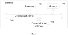
- the terminal may include a processor 710, a communication interface 720, a memory 730, and a communication bus 740.
- the processor 710, the communication interface 720, and the memory 730 communicate with each other through the communication bus 740.
- the processor 710 may invoke computer programs stored on the memory 730 and executable on the processor 710 to perform the following steps:
- the processor when executing the programs, further implements the following step: determining whether to transmit the one or more second target uplink channels.
- determining whether to transmit the one or more first target uplink channels includes: when a symbol set in which the one or more first target uplink channels is located does not include a first unavailable symbol, determining to transmit the one or more first target uplink channels; and
- determining whether to transmit the one or more second target uplink channels includes: when the symbol set in which the one or more second target uplink channels is located does not include a third unavailable symbol, determining to transmit the one or more second target uplink channels.
- the third unavailable symbol includes at least one of the following symbols: a DL symbol configured by a higher layer signaling, a FL symbol configured by a higher layer signaling, a symbol scheduled by DCI for downlink transmission, a symbol indicated as DL or FL by indication information in DCI for indicating a structure of a time unit, a symbol for a GP, a symbol for a SSB transmission, an unavailable symbol preconfigured by signaling or a symbol within BWP switching time.
- the plurality of uplink channels include at least one channel configured by the higher layer signaling for transmission.
- determining whether to transmit the one or more first target uplink channels includes: when each of the one or more first target uplink channels is a channel configured by the higher layer signaling for transmission, determining to transmit the first target uplink channels; and determining, from the plurality of uplink channels, the candidate uplink channels which could be transmitted includes: determining the candidate uplink channels which could be transmitted from the channels configured by the higher layer signaling for transmission.
- determining whether to transmit the one or more second target uplink channel includes: when each of the one or more second target uplink channels is a channel configured by the higher layer signaling for transmission, determining to transmit the one or more second target uplink channels.
- the channel configured by the higher layer signaling for transmission includes at least one of the following channels: a physical uplink shared channel (PUSCH) without a corresponding physical downlink control channel (PDCCH), and a PUCCH transmission using a physical uplink control channel (PUCCH) resource corresponding to the semi-persistent scheduling (SPS), a PUCCH transmission using a PUCCH resource corresponding to channel state information (CSI) or a PUCCH transmission using a PUCCH resource corresponding to a scheduling request (SR).
- PUSCH physical uplink shared channel
- PUCCH physical uplink control channel
- SPS semi-persistent scheduling
- CSI channel state information
- SR scheduling request
- the above terminal can implement all steps of the method on the terminal side and achieve the same beneficial effects, and the same steps of the method and the same beneficial effects in the terminal as the terminal side method embodiments will not be repeated here.
- the logic instructions in the memory 730 described above may be implemented in the form of a software functional unit and may be stored in a computer readable storage medium while being sold or used as a separate product. Therefore, the embodiments of the present application provide a software product, which is stored in a storage medium and includes several instructions to cause a computer device (for example, a personal computer, server, or network device, etc.) to perform all or part of steps of the method described in various embodiments.
- the storage medium described above includes various media that can store program codes, such as U disk, mobile hard disk, read-only memory (ROM), random access memory (RAM), magnetic disk, or optical disk.
- the base station may include a processor 810, a communication interface 820, a memory 830, and a communication bus 840.
- the processor 810, the communication interface 820, and the memory 830 communicate with each other through the communication bus 840.
- the processor 810 may invoke computer programs stored on the memory 830 and executable on the processor 810 to perform the following steps:
- the processor when executing the program, further implements the following step: determining whether to receive the one or more second target uplink channels.
- the logic instructions in the memory 830 described above may be implemented in the form of a software functional unit and may be stored in a computer readable storage medium while being sold or used as a separate product. Therefore, the embodiments of the present application provide a software product, which is stored in a storage medium including several instructions to cause a computer device (for example, a personal computer, server, or network device, etc.) to perform all or part of steps of the method described in various embodiments.
- the storage medium described above includes various media that can store program codes such as U disk, mobile hard disk, read-only memory (ROM), random access memory (RAM), magnetic disk, or optical disk.
- the present application provides a non-transitory computer-readable storage medium having computer programs stored thereon.
- the computer programs when executed by the processor, cause the processor to perform the steps of the method mentioned above according to the embodiments.
- non-transitory computer-readable storage medium can implement all steps of the method of various embodiments and achieve the same beneficial effects, and the same steps of the method and the same beneficial effects in the on-transient computer-readable storage medium as the method embodiments will not be repeated here.
- the device embodiments described above are merely illustrative, wherein the units described as separate components may or may not be physically separated, and the components displayed as units may or may not be physical units, that is, may be located at the same place, or they can be distributed to multiple network units. Some or all of the modules may be selected according to actual needs to achieve the purpose of the solution of the present embodiment. Those of ordinary skill in the art can understand and implement the embodiments described above without paying creative labors.
- the various embodiments can be implemented by means of software and a necessary general hardware platform, and of course, by hardware. Therefore, the embodiments of the present application provide a software product, which is stored in a storage medium such as ROM/RAM, magnetic Discs, optical discs, etc., including several instructions to cause a computer device (for example, a personal computer, server, or network device, etc.) to perform various embodiments or a part of the methods described in various embodiments.
- a computer device for example, a personal computer, server, or network device, etc.
Landscapes
- Engineering & Computer Science (AREA)
- Signal Processing (AREA)
- Computer Networks & Wireless Communication (AREA)
- Mobile Radio Communication Systems (AREA)
Description
- The present application relates to the technical field of communication, and in particular, to a method for uplink channel transmission, a terminal, and a base station.
- In 5G New Radio (NR), neither simultaneous transmission (resources overlapping in time domain) of Physical Uplink Control Channel (PUCCH) and Physical Uplink Shared Channel (PUSCH) nor simultaneous transmission of multiple overlapped PUCCHs on the same carrier is supported. PUCCH is used to carry uplink control information (UCI), which may include one or more combinations of a hybrid automatic repeat request-acknowledge character (HARQ-ACK), channel state information (CSI) and a scheduling request (SR).
- When all or part of symbols of PUCCH and PUSCH overlap, it is required to determine whether the first symbol of the earliest channel in the PUCCH and PUSCH satisfies a predefined timeline. When the predefined timeline is satisfied, the UCI carried on the PUCCH is transferred to the PUSCH for transmission, such that the PUCCH is no longer transmitted, thereby avoiding simultaneous transmission of the PUCCH and PUSCH. If there are multiple overlapped PUSCHs and PUCCHs simultaneously, a PUSCH may be selected from the multiple PUSCHs according to a predetermined rule, for example, the PUSCH carrying aperiodic channel state information (A-CSI) (if any) is preferentially selected. If there is no PUSCH carrying A-CSI, a PUSCH with a corresponding physical downlink control channel (PDCCH) is preferentially selected. When there are PUSCHs of the same type (for example, PUSCHs with corresponding PDCCHs, or PUSCHs without corresponding PDCCHs if there is no PUSCH with a corresponding PDCCH) on multiple carriers at the same time, the PUSCH on a carrier having the smallest carrier number is selected, and the PUSCH earliest in time is selected when there are multiple overlapped PUSCHs and PUCCHs on the selected carrier.
- When the PUCCHs carrying the UCI overlap in time domain, it is also required to determine whether the first symbol of the earliest initial channel in the overlapped PUCCHs satisfies the predefined timeline. When the predefined timeline is satisfied, the UCIs on a plurality of PUCCHs can be transmitted in combination in a PUCCH channel, thereby avoiding parallel transmissions of the plurality of PUCCHs. It is defined in R15 that there is no case where the timeline is not satisfied, that is, the case where the timeline is not satisfied is an incorrect scheduling and no cation is performed. When scheduling and configurations are performed in the respective base stations, it is required to ensure that the overlapped channels always satisfy the timeline.
- However, when there are overlaps of uplink channels, some of the overlapped uplink channels may not be used for transmission since there is no available symbol in a set of symbols for these channels. There is no clear scheme about how to perform uplink channel transmission in such case.
-
US2017135090A1 discloses a user equipment (UE) for reporting uplink control information (UCI) when one or more Licensed-Assisted Access (LAA) serving cells are configured. The UE includes a processor and memory in electronic communication with the processor. Instructions stored in the memory are executable to determine if physical uplink shared channel (PUSCH) transmissions are scheduled on LAA serving cells and licensed cells. The instructions are also executable to determine a type of UCI to be reported. The instructions are further executable to determine a channel and cells to carry different UCI. The instructions are additionally executable to transmit the channel on the cells determined to carry UCI. The instructions are also executable to determine whether a LAA PUSCH is transmitted and UCI is multiplexed. The instructions are further executable to drop LAA PUSCH or transmit LAA PUSCH subject to listen-before-talk (LBT). -
KR20170112633A -
EP2660992A1 discloses a method and a device for transmitting data. The method includes: a UE determining, according to a preset rule, whether to transmit PUCCH data and/or PUSCH data and/or an SRS or not on a last symbol of a current subframe; the UE determining the PUCCH data and/or the PUSCH data to be transmitted on the current subframe according to availability of the last symbol of the current subframe for transmitting the PUCCH data and/or the PUSCH data; and the UE transmitting the PUCCH data and/or the PUSCH data on the current subframe and/or transmitting the SRS on the last symbol of the current subframe. -
US20190261391A1 discloses an apparatus of a user equipment (UE) to operate in a New Radio (NR) system, which comprises one or more baseband processors to determine if two or more uplink signals partially overlap, determine a multiplexing rule, a dropping rule, or a priority rule for the two or more uplink signals, and to multiplex, drop, or prioritize the two or more uplink signals for transmission according to the multiplexing rule, dropping rule, or priority rule, and a memory to store two or more uplink signals. - Embodiments of the present application provide a method for uplink channel transmission, a terminal, and a base station, for ensuring normal transmission of a system when the uplink channels overlap and improving transmission performance of the system. The invention is limited by the appended set of independent claims. Further embodiments are defined by the dependent claims.
- In order to more clearly illustrate technical solutions disclosed in the embodiments of the present application or the prior art, the drawings used in the descriptions of the embodiments or the prior art will be briefly described below. The drawings in the following description are only illustrated as certain embodiments of the present application, and other drawings can be obtained according to the illustrated drawings without any creative work for those skilled in the art.
-
FIG. 1-1 is a first schematic diagram showing use of timeline in a multiplexing transmission process; -
FIG. 1-2 is a second schematic diagram showing use of timeline in a multiplexing transmission process; -
FIG. 1-3 is a third schematic diagram showing use of timeline in a multiplexing transmission process; -
FIG. 1-4 is a fourth schematic diagram showing use of timeline in a multiplexing transmission process; -
FIG. 2 is a flowchart showing steps ofmode 1 in a method for uplink channel transmission performed by a terminal according to an embodiment of the present application; -
FIG. 3 is a flowchart showing steps ofmode 2 in a method for uplink channel transmission performed by a terminal according to an embodiment of the present application; -
FIG. 4 is a flowchart showing steps ofmode 1 in a method for uplink channel transmission performed by a base station according to an embodiment of the present application; -
FIG. 5 is a flowchart showing steps ofmode 2 in a method for uplink channel transmission performed by a base station according to an embodiment of the present application; -
FIG. 6-1 is a schematic diagram of transmission whenMode 1 is specified to be used in a first embodiment of the present application; -
FIG. 6-2 is a schematic diagram of transmission whenMode 2 is specified to be used in a first embodiment of the present application; -
FIG. 6-3 is a schematic diagram of transmission whenMode 1 is specified to be used in a second embodiment of the present application; -
FIG. 6-4 is a first schematic diagram of transmission whenMode 2 is specified to be used in a second embodiment of the present application; -
FIG. 6-5 is a second schematic diagram of transmission whenMode 2 is specified to be used in a second embodiment of the present application; -
FIG. 6-6 is a third schematic diagram of transmission whenMode 2 is specified to be used in a second embodiment of the present application; -
FIG. 6-7 is a schematic diagram of transmission whenMode 1 is specified to be used in a third embodiment of the present application; -
FIG. 6-8 is a schematic diagram of transmission whenMode 2 is specified to be used in a third embodiment of the present application; -
FIG. 7 is a schematic diagram of structure of a terminal according to an embodiment of the present application; and -
FIG. 8 is a schematic diagram of structure of a base station according to an embodiment of the present application. - In order to make the object, technical solutions and advantages of the embodiments of the present application much clearer, the technical solutions in the embodiments of the present application are clearly and completely described in the following with reference to the accompanying drawings in the embodiments of the present application. These embodiments are a part of embodiments of the present application, and not all of the embodiments. All other embodiments obtained by a person of ordinary skill in the art based on the embodiments of the present application without any creative work belong to the scope of the present application.
- In 5G NR, neither simultaneous transmission of PUCCH and PUSCH (resource overlapping in time domain) nor simultaneous transmission of multiple overlapped PUCCHs on the same carrier is supported. In this case, when two PUCCHs overlap with each other, a multiplexing transmission rules can be defined as follows.
- When a PUCCH carrying SR overlaps with a PUCCH carrying HARQ-ACK, the PUCCH carrying HARQ-ACK uses PUCCH format 0, and the PUCCH carrying SR can use either format 0 or
format 1, the SR and HARQ-ACK are multiplexed and transmitted on the PUCCH resource of HARQ-ACK. That is, the HARQ-ACK is transmitted on the PUCCH resource of the HARQ-ACK by selecting a cyclic shift (CS) corresponding to the HARQ-ACK depend on whether a positive SR or a negative SR exists, which is implicitly indicated as positive or negative. - When PUCCH carrying SR overlaps with PUCCH carrying HARQ-ACK, the PUCCH carrying SR uses format 0 and the PUCCH carrying HARQ-ACK uses
format 1, SR is dropped. That is, multiplexing transmission is not performed in such case. - When PUCCH carrying SR overlaps with PUCCH carrying HARQ-ACK, the PUCCH carrying SR uses
format 1 and the PUCCH carrying HARQ-ACK usesformat 1, HARQ-ACK is transmitted on the PUCCH resource of SR when SR is a positive, such that the simultaneous transmission of SR is implicitly indicated by transmitting HARQ-ACK using the PUCCH resource corresponding to SR, otherwise (i.e., negative SR), the HARQ-ACK is transmitted on the PUCCH resource of the HARQ-ACK. - When PUCCH carrying SR overlaps with PUCCH carrying HARQ-ACK, the PUCCH carrying HARQ-ACK uses
format format 1, a set of PUCCH resources is determined according to the total number of bits of the SR and HARQ-ACK. According to a PUCCH resource indication field in a Downlink Control Information (DCI) corresponding to the HARQ-ACK, a PUCCH resource is determined from the determined set of PUCCH resources for simultaneously transmitting the SR and HARQ -ACK, wherein SR is X bits, indicating SR status of X SRs overlapping with the HARQ-ACK (which one is positive, or both are negative). That is, whether SR is positive or negative, X-bit SR is always transmitted, so as to avoid change of the number of bits of UCI transmitted on the PUCCH resource of the HARQ-ACK due to the SR state. - When PDSCH carrying semi-persistent scheduling (SPS) HARQ-ACK (that is, HARQ-ACK corresponding to SPS, that is, HARQ-ACK without corresponding PDCCH) and/or SR overlaps with PUCCH carrying CSI, the SPS HARQ-ACK and/or SR are transferred to a PUCCH resource corresponding to the CSI and multiplexed and transmitted with the CSI.
- When PDCCH carrying HARQ-ACK with a corresponding PDCCH (that is, when the HARQ-ACK is feedback information of PDSCH, the PDCCH that schedules the PDSCH corresponds to the HARQ-ACK, and when the HARQ-ACK is feedback information of the PDCCH indicating release of downlink SPS resources, the PDCCH corresponds to the HARQ-ACK) overlaps with PUCCH carrying CSI, a set of PUCCH resources is selected from a plurality of sets of PUCCH resources according to the total number of bits of the SR and HARQ-ACK; and a PUCCH resource is determined from the selected set of PUCCH resources for simultaneously carrying the HARQ-ACK and CSI, according to a PUCCH resource indication field in DCI corresponding to the HARQ-ACK. In this case, the re-determined PUCCH resource may be the same as or different from the original PUCCH resource carrying the HARQ-ACK (if different, it is a new PUCCH resource). It is not expected that the terminal is configured to support simultaneous transmission of the HARQ-ACK and CSI when only one set of PUCCH resources is configured.
- When there is an overlap among more than 2 PUCCHs, it is assumed that the PUCCHs in a time slot constitute a set Q, an uplink channel in the set Q which starts earliest is determined as channel A, and a set X of channels that overlap with channel A is determined. Above-mentioned multiplexing transmission rules are applied to UCI on channel A and channel X to obtain a channel resource for multiplexing transmission, and channel A in the set Q and channel X are replaced with the channel resource for multiplexing transmission. The above steps are repeated to determine channel A and channel X in a new set Q and so on, until a plurality of PUCCHs that do not overlap in time domain are obtained.
- In the above-mentioned overlapped multiple PUCCHs or overlapped PUCCHs and PUSCHs, when one of the PUCCHs or PUSCHs has corresponding DCI (for example, the HARQ-ACK carried on the PUCCH is a HARQ-ACK of the PDSCH scheduled by DCI or is an DCI indicating release of a downlink SPS resource, the DCI scheduling PDSCH or the DCI indicating the release of downlink SPS resource is the DCI corresponding to the PUCCH, for example, the DCI scheduling the PUSCH is the DCI corresponding to the PUSCH), the first symbol of the channel among the overlapped channels that starts earliest (if there are multiple channel having the same starting time, any one of them is selected) needs to meet the following timelines.
- Timeline1: the first symbol is not earlier than a symbol including a cyclic prefix (CP) starting later T1 time after the last symbol of any PDSCH or SPS PDSCH release that requires HARQ-ACK feedback on PUCCH, that is, a time interval between the first symbol and the last symbol of any of the above PDSCH or SPS PDSCH release is not less than T1 time. T1 is related to a processing delay of PDSCH or SPS PDSCH release and can be calculated according to the formula and related parameters. The timeline is intended to ensure that the acquisition and preparation of the HARQ-ACK can be completed before the transmission of the finally determined channel for transmitting the HARQ-ACK starts.
- Timeline2: the first symbol is not earlier than a symbol including a CP starting later T2 time after the last symbol of any PDCCH (including the PDCCH indicating SPS PDSCH release) scheduling PDSCH (if any) and PUSCH (if any), that is, a time interval between the first symbol and the last symbol of any of above PDCCHs is not less than T2 time. T2 is related to the processing delay of PUSCH and can be calculated according to the formula and related parameters. The timeline is intended to ensure that when there are a plurality of UCI multiplexing transmissions, the acquisition and multiplexing processing of the various UCIs can be completed before the transmission of the target channel for transmitting the UCI starts.
- For example, as shown in
FIGS. 1-1 to 1-4 (that is,FIG. 1-1, FIG. 1-2, FIG. 1-3 , andFIG. 1-4 ), if there are a PDCCH scheduling PDSCH (DL DCI in the figures) and a PDCCH scheduling PUSCH (UL DCI in the figures.) at the same time, it is required to satisfy a T2 interval between the first symbol and the last symbols of all PDCCHs, that is, it is actually required to satisfy the T2 interval between the first symbol and the last PDCCH. However, if there are a plurality of PDSCHs at the same time, it is required to satisfy a T1 interval between the first symbol and the last symbols of all PDSCHs, that is, it is actually required to satisfy the T1 interval between the first symbol and the last PDSCH. The use of the above timeline is certainly not limited to the scenarios shown inFIGS. 1-1 to 1-4 . ForFIGS. 1-3 and1-4 , when the HARQ-ACK carried on the PUCCH has no corresponding DCI (that is, the HARQ-ACK is the HARQ-ACK of the SPS PDSCH), in which case there is no DL DCI in theFIGS. 1-3 and1-4 , only T1 needs to be checked and T2 does not need to be checked. ForFIGS. 1-1 and 1-2 , if the HARQ-ACK carried on the PUCCH has no corresponding DCI (that is, the HARQ-ACK is the HARQ-ACK of the SPS PDSCH), in which case there is no DL DCI in theFIGS. 1-1 and 1-2 , and if the PUSCH also has no corresponding DCI, in which case there is no DL DCI in theFIGS. 1-1 and 1-2 , only T1 needs to be checked and T2 does not need to be checked. If the PUCCH overlaps with the PUSCH and the PUCCH carries CSI and/or SR, T1 does not need to be checked, and further, if the PUSCH has no corresponding DCI, T2 does not need to be checked. - In addition, if PUSCHs carrying CSI overlap on the same carrier and in time domain, a selection is made according to priorities of the carried CSI, so as to a PUSCH carrying CSI with a higher priority is selected for transmission, and a PUSCH carrying CSI with a lower priority is dropped. In an embodiment, CSI may include aperiodic CSI (A-CSI), semi-persistent CSI (SP-CSI), periodic CSI (P-CSI), which have the priorities of A-CSI, SP-CSI CSI, P-CSI from high to low.
- Although the above-mentioned multiplexing transmission rules can be used to implement non-simultaneous transmission between overlapped uplink channels, some of the overlapped uplink channels may be unable to transmit since there is an unavailable symbol in a set of symbols for the overlapped uplink channels. There is no clear scheme about how to deal with overlapped uplink channels and to solve the problem of overlapped transmission.
- In view of this, the present application provides specific implementation. The embodiments of the present application are specifically described below.
- When a plurality of uplink channels overlap in time domain, the terminal side may perform uplink channel transmission through any one of the following two processing modes.
-
Mode 1, referring toFIG. 2 ,Mode 1 includes the following steps:
step 201: firstly processing the plurality of uplink channels based on a multiplexing rule to determine one or more first target uplink channels to be transmitted, and then determining whether to transmit the one or more first target uplink channels. - In this mode, specifically, by firstly processing a plurality of uplink channels based on the multiplexing rule to determine the one or more first target uplink channels to be transmitted and then determining whether to transmit the one or more first target uplink channels, an order of processes for processing the plurality of uplink channels based on the multiplexing rule and for determining whether to transmit the uplink channels is clearly defined, such that the terminal can directly determine the transmission status of the uplink channels according to the order, thereby ensuring the normal transmission of a system.
- In addition, specifically, it should be noted here that, for the process for processing the plurality of uplink channels based on the multiplexing rule, reference may be made to the above described process for the multiplexing transmission rule, which will not be repeated here.
-
Mode 2, referring toFIG. 3 ,Mode 2 includes the following steps:
step 301: firstly determining, from the plurality of uplink channels, candidate uplink channels which could be transmitted, and then processing the candidate uplink channels based on a multiplexing rule to determine one or more second target uplink channels to be transmitted. - In this mode, specifically, by firstly determining, from the plurality of uplink channels, candidate uplink channels which could be transmitted and then processing the candidate uplink channels based on a multiplexing rule to determine the one or more second target uplink channels to be transmitted, an order of processes for determining whether to transmit the uplink channel and for processing the plurality of uplink channels based on the multiplexing rules is clearly determined, such that a terminal can directly determine the transmission status of the uplink channels according to the order, thereby ensuring the normal transmission of a system.
- Specifically, it should be noted here that, for the process for processing the candidate uplink channels based on the multiplexing rule, reference may be made to the above described process for the multiplexing transmission rule, which will not be repeated here. According to the embodiments of the present application, when a plurality of uplink channels overlap in time domain, by setting set an order of the steps of processing the plurality of uplink channels based on a multiplexing rule to determine to determine one or more first target uplink channels to be transmitted and determining whether to transmit the one or more first target uplink channels or an order of determining, from the plurality of uplink channels, candidate uplink channels which could be transmitted and processing the candidate uplink channels based on a multiplexing rule to determine one or more second target uplink channels to be transmitted, the terminal can clearly determine a transmission status of the uplink channels based on the determined order of the processes for determining whether to transmit the uplink channel and for processing the plurality of uplink channels based on the multiplexing rule, thereby ensuring the normal transmission of a system and improving the transmission performance of the system.
- In addition, the process for determining whether to transmit the uplink channel is described below.
- According to an embodiment, in
Mode 1, when determining whether to transmit the first target uplink channels, it may be checked whether the symbol set in which transmission of the one or more first target uplink channels is located includes a first unavailable symbol. When the symbol set in which the one or more first target uplink channels is located does not include the first unavailable symbol, it is determined to transmit the one or more first target uplink channels. - When the symbol set in which the one or more first target uplink channels is located includes a first unavailable symbol, it is determined not to transmit the one or more first target uplink channels.
- In an embodiment, the first unavailable symbol may include at least one of the following symbols:
a downlink (DL) symbol configured by a higher layer signaling, a flexible (FL) symbol configured by a higher layer signaling, a symbol scheduled by DCI for downlink transmission, a symbol indicated as DL or FL by indication information in DCI for indicating a structure of a time unit, a symbol for a guard period (referred to as GP), a symbol for a synchronization signal block (referred to as SSB) transmission, an unavailable symbol preconfigured by signaling or a symbol within bandwidth part (referred to as BWP) switching time. - In an embodiment, the DCI for indicating the structure of the time unit is specifically a DCI for carrying indication information indicating the uplink and downlink structures, for example, DCI format 2-0 scrambled using a slot format indicator-radio network temporary identity (simply referred to as SFI-RNTI).
- In an embodiment, the action of DCI scheduling for downlink transmission may include action of instructing the terminal to receive PDSCH or channel state information reference signal (CSI-RS for short) by DCI format 1_0, DCI format 1_1 or DCI format 0_1.
- In addition, in above-mentioned
mode 2, when determining, from the plurality of uplink channels, candidate uplink channels which could be transmitted, for each uplink channel of the plurality of uplink channels, it may also be possible to detect whether the symbol set in which the uplink channel is located includes a second unavailable symbol. When the symbol set in which the uplink channel is located does not include the second unavailable symbol, the uplink channel may be determined as a candidate uplink channel. When the symbol set in which the uplink channel is located includes the second unavailable symbol, the uplink channel cannot be determined as a candidate uplink channel. - In an embodiment, the second unavailable symbol may similarly include at least one of the following symbols:
a DL symbol configured by a higher layer signaling, a FL symbol configured by a higher layer signaling, a symbol scheduled by DCI for downlink transmission, a symbol indicated as DL or FL by indication information in DCI for indicating a structure of a time unit, a symbol for a GP, a symbol for a SSB transmission, an unavailable symbol preconfigured by signaling or a symbol within BWP switching time. - It should be noted here that, for downlink transmission performed by DCI and DCI scheduling, reference may be made to the description of downlink transmission performed by DCI and DCI scheduling in the first unavailable symbol, and details are not repeated here.
- Further, in
mode 2, after the one or more second target uplink channels to be transmitted are determined, it can further be determined whether to transmit the one or more second target uplink channels. - According to an embodiment, when determining whether to transmit the one or more second target uplink channels, it can be detected whether the symbol set in which the one or more second target uplink channels is located includes a third unavailable symbol. When the symbol set in which the second target uplink channel is located does not include a third unavailable symbol, it is determined to transmit the one or more second target uplink channels.
- When the symbol set in which the one or more second target uplink channels is located includes the third unavailable symbol, it is determined not to transmit the one or more second target uplink channels.
- In an embodiment, the third unavailable symbol may include at least one of the following symbols:
a DL symbol configured by a higher layer signaling, a FL symbol configured by a higher layer signaling, a symbol scheduled by DCI for downlink transmission, a symbol indicated as DL or FL by indication information in DCI for indicating a structure of a time unit, a symbol for a GP, a symbol for a SSB transmission, an unavailable symbol preconfigured by signaling or a symbol within BWP switching time. - It should be noted here that, for downlink transmission performed by DCI and DCI scheduling, reference may be made to the description of downlink transmission performed by DCI and DCI scheduling in the first unavailable symbol, and details are not repeated here.
- It should also be noted that the first unavailable symbol and the second unavailable symbol may be the same or different from each other, which are not specifically limited here. In addition, the second unavailable symbol and the third unavailable symbol may be the same or different from each other, which is also not specifically limited here.
- For example, the first unavailable symbol may include at least a DL symbol configured by a higher layer signaling, a symbol scheduled by DCI for downlink transmission, a symbol indicated as DL or FL by indication information in DCI for indicating a structure of a time unit, and a symbol for a SSB transmission, while the second unavailable symbol may be the same as the first unavailable symbol or may include at least a DL symbol configured by a higher layer signaling and a symbol for a SSB transmission. The third unavailable symbol may include at least a DL symbol configured by a higher layer signaling, a symbol scheduled by DCI for downlink transmission, a symbol indicated as DL or FL by indication information in DCI for indicating a structure of a time unit and a symbol for a SSB transmission.
- In addition, it should be further noted that the plurality of uplink channels in the present embodiment include at least one channel configured by a higher layer signaling for transmission, that is, a semi-static channel.
- In this case, in above-mentioned
mode 1, when determining whether to transmit the one or more first target uplink channels, it may be detected whether each of the one or more first target uplink channels is a channel configured by a higher layer signaling for transmission, and when each of the first target uplink channels is a channel configured by the higher layer signaling for transmission, it is determined to transmit the one or more first target uplink channels. - In addition, in above-mentioned
mode 2, when determining, from the plurality of uplink channels, candidate uplink channels which could be transmitted, the candidate uplink channels which could be transmitted may be determined from the channels configured by the higher layer signaling for transmission. - Specifically, when determining whether to transmit the one or more second target uplink channels, it may be detected whether each of the second target uplink channels is a channel configured by a higher layer signaling for transmission, and when each of the second target uplink channels is a channel configured by the higher layer signaling for transmission, it is determined to transmit the one or more second target uplink channels. Specifically, the channel configured by a higher layer signaling for transmission may include at least one of the following channels: a PUSCH without a corresponding PDCCH, a PUCCH transmission using a PUCCH resource corresponding to SPS, a PUCCH transmission using a PUCCH resource corresponding to CSI, or a PUCCH transmission using a PUCCH resource corresponding to a SR.
- Specifically, the PUSCH not corresponding to the PDCCH may include a cell group PUSCH (referred to as CG PUSCH) and a PUSCH carrying semi-persistent channel state information (referred to as SP-CSI). In addition, the PUCCH transmitted using the PUCCH resource corresponding to SPS includes a PUCCH carrying HARQ-ACK of the SPS PDSCH.
- In this way, when the plurality of uplink channels overlap in time domain, by setting the order of processes for determining whether to transmit the uplink channel and for processing the plurality of uplink channels based on the multiplexing rule, the terminal can clearly define a transmission status of the uplink channels, thereby ensuring the normal transmission of the system and improve the transmission performance of the system.
- In addition, when a plurality of uplink channels overlap in time domain, the base station side can perform the uplink channel transmission through any one of the following two processing modes:
Mode 1, referring toFIG. 4 ,Mode 1 includes the following step:
step 401: firstly processing the plurality of uplink channels based on a multiplexing rule to determining one or more first target uplink channels to be received, and then determining whether to receive the one or more first target uplink channels. - In this mode, specifically, by firstly processing a plurality of uplink channels based on the multiplexing rule to determine the one or more first target uplink channels to be received and then determining whether to receive the one or more first target uplink channels, an order between processes for processing the plurality of uplink channels based on the multiplexing rule and for determining whether to receive the uplink channels is clearly determined, such that the base station can directly determine a reception status of the uplink channels according to the order and avoid the case that the terminal and the base station have non-consistent knowledge on the transmission situation due to unclear order of processing and determining processes, thereby ensuring the normal transmission of the system.
- It should be noted here that, in the present mode, the terminal also uses this mode to determine the order of the above two processes, that is, correspondingly, the terminal firstly processes the plurality of uplink channels based on the multiplexing rule to determines the one or more first target uplink channels to be transmitted and then determines whether to transmit the one or more first target uplink channels, so that the terminal and the base station can have consistent knowledge on the transmission status, thereby ensuring the normal transmission of the system.
- It should be noted here that, for the process of processing the plurality of uplink channels based on the multiplexing rule, reference may be made to the above described process for the multiplexing transmission rule, which will not be repeated here.
-
Mode 2, referring toFIG. 5 ,Mode 2 includes the following step:
step 501: firstly determining, from the plurality of uplink channels, candidate uplink channels which could be received, and then processing the candidate uplink channels based on a multiplexing rule to determine one or more second target uplink channels to be received. - In this mode, specifically, by first determining, from the plurality of uplink channels, candidate uplink channels which could be received, and then processing the candidate uplink channels based on a multiplexing rule to determine the one or more second target uplink channels to be received, an order of processes for determining whether to receive the uplink channel and for processing the plurality of uplink channels based on the multiplexing rule is clearly determined, such that the terminal can directly determine the reception status of the uplink channels according to the order and avoid the case that the terminal and the base station have non-consistent knowledge on the transmission situation due to an unclear order of processing and determining processes, thereby ensuring the normal transmission of the system.
- It should be noted here that, in the present mode, the base station also uses this mode to determine the order of the above two processes, that is, correspondingly, the terminal firstly determines, from the plurality of uplink channels, candidate uplink channels which could be transmitted, and then processes the candidate uplink channels based on a multiplexing rule to determine the one or more second target uplink channels to be transmitted, so that the terminal and the base station can have consistent knowledge on the transmission status, thereby ensuring the normal transmission of the system.
- It should be noted here that, for the process for processing the candidate uplink channel based on the multiplexing rule, reference may be made to the above described process for the multiplexing transmission rule, which will not be repeated here.
- In addition, the process for determining whether to receive the uplink channel is further described below.
- In
Mode 1, when determining whether to receive the one or more first target uplink channels, it can be detected whether the symbol set in which the one or more first target uplink channels is located includes a first unavailable symbol, and when the symbol set in which the first target uplink channels is located does not include a first unavailable symbol, it is determined to receive the one or more first target uplink channels. - In an embodiment, the first unavailable symbol may include at least one of the following symbols:
a downlink (DL) symbol configured by a higher layer signaling, a flexible (FL) symbol configured by a higher layer signaling, a symbol scheduled by DCI for downlink transmission, a symbol indicated as DL or FL by indication information in DCI for indicating a structure of a time unit, a symbol for a guard period (referred to as GP), a symbol for a synchronization signal block (referred to as SSB) transmission, an unavailable symbol preconfigured by signaling or a symbol within bandwidth part (referred to as BWP) switching time. - It should be noted here that, for downlink transmission performed by DCI and DCI scheduling, reference may be made to the description of downlink transmission performed by DCI and DCI scheduling in the first unavailable symbol at a terminal side, and details are not repeated here.
- In
Mode 2, when determining, from the plurality of uplink channels, candidate uplink channels which could be received, for each uplink channel of the plurality of uplink channels, it may be possible to detect whether a symbol set in which the uplink channel is located includes a second unavailable symbol. When the symbol set in which the uplink channel is located does not include the second unavailable symbol, the uplink channel may be determined as a candidate uplink channel. - In an embodiment, the second unavailable symbol may include at least one of the following symbols:
a DL symbol configured by a higher layer signaling, a FL symbol configured by a higher layer signaling, a symbol scheduled by DCI for downlink transmission, a symbol indicated as DL or FL by indication information in DCI for indicating a structure of a time unit, a symbol for a GP, a symbol for a SSB transmission, an unavailable symbol preconfigured by signaling or a symbol within BWP switching time. - It should be noted here that, for downlink transmission performed by DCI and DCI scheduling, reference may be made to the description of downlink transmission performed by DCI and DCI scheduling in the first unavailable symbol at a terminal side, and details are not repeated here.
- Further, in
Mode 2, after determining the one or more second target uplink channels to be received, it needs also to be determined whether to receive the one or more second target uplink channels. - According to an embodiment, when determining whether to receive the one or more second target uplink channels, it can be detected whether the symbol set in which the one or more second target uplink channels is located includes a third unavailable symbol, and when the symbol set in which the one or more second target uplink channels is located does not include a third unavailable symbol, it is determined to receive the one or more second target uplink channels.
- In an embodiment, the third unavailable symbol includes at least one of the following symbols:
a DL symbol configured by a higher layer signaling, a FL symbol configured by a higher layer signaling, a symbol scheduled by DCI for downlink transmission, a symbol indicated as DL or FL by indication information in DCI for indicating a structure of a time unit, a symbol for a GP, a symbol for a SSB transmission, an unavailable symbol preconfigured by signaling or a symbol within BWP switching time. - It should also be noted that the first unavailable symbol and the second unavailable symbol may be the same or different from each other, which are not specifically limited here. In addition, the second unavailable symbol and the third unavailable symbol may be the same or different from each other, which is also not specifically limited here. Also, examples of the first, second and third unavailable symbols may refer to those illustrated for the terminal side, which will not be repeated here.
- In addition, it should be further noted that the plurality of uplink channels in the present embodiment include at least one channel configured by the higher layer signaling for transmission, that is, a semi-static channel.
- In this case, in above-mentioned
Mode 1, when determining whether to receive the one or more first target uplink channels, it may be detected whether each of the one or more first target uplink channels is a channel configured by a higher layer signaling for transmission, and when each of the first target uplink channels is a channel configured by the higher layer signaling for transmission, it is determined to receive the one or more first target uplink channels. - In addition, in above-mentioned
Mode 2, when determining, from the plurality of uplink channels, candidate uplink channels which could be received, the candidate uplink channels which could be received may be determined from the channels configured by the higher layer signaling for reception. - Also, when determining whether to receive the one or more second target uplink channels, it may be detected whether each of the one or more second target uplink channels is a channel configured by a higher layer signaling for transmission, and when each of the one or more second target uplink channels is a channel configured by the higher layer signaling for transmission, it is determined to receive the one or more second target uplink channels.
- Specifically, the channel configured by the higher layer signaling for transmission may include at least one of the following channels: a PUSCH without a corresponding PDCCH, a PUCCH transmission using a PUCCH resource corresponding to SPS, a PUCCH transmission using a PUCCH resource corresponding to CSI, or a PUCCH transmission using a PUCCH resource corresponding to a SR.
- Specifically, for the description of the PUSCH and the PUCCH transmitted using the PUCCH resource corresponding to the SPS, reference may be made to the terminal side, and details are not repeated here.
- In this way, according to this embodiment, when the plurality of uplink channels overlap in time domain, by setting the order of processes for determining whether to receive the uplink channel and for processing the plurality of uplink channels based on the multiplexing rule, the base station can clearly define a transmission status of the uplink channels, so as to avoid the case that the terminal and the base station have non-consistent knowledge on the transmission situation due to unclear order of processing and determining processes when the uplink channels overlap, thereby ensuring the normal transmission of the system and improving the transmission performance of the system. The processes mentioned above will be described below by way of specific embodiments.
- There is a PUCCH transmission and a PUSCH transmission on component carrier 1 (CC1) and CC2, respectively, and the PUCCH and PUSCH overlap in time domain. The PUCCH carries HARQ-ACK of a SPS PDSCH (referred to as SPS HARQ-ACK), and PUSCH has no corresponding PDCCH (i.e., CG PUSCH):
If the terminal and the base station agree to useMode 1 described above, assuming that a DL symbol configured by a higher layer signaling, a symbol scheduled by DCI for downlink transmission, a symbol indicated as DL or FL by indication information in DCI for indicating a structure of a time unit, and a symbol for a SSB transmission are all unavailable: at the terminal side, based on the multiplexing transmission rule for the overlapped PUCCH and PUSCH, firstly determining to transfer HARQ-ACK on the PUCCH to the PUSCH for transmission, thereby not transmitting the PUCCH, that is, obtaining the finally transmitted channel PUSCH; and then determining whether the PUSCH includes an unavailable symbol. Since the PUSCH is full-filled with UL symbols and does not include any unavailable symbol, the PUSCH is transmitted specifically as shown inFIG. 6-1 . At the base station side, in the consistent mode with that at the terminal side, determining that the terminal transfers the HARQ-ACK to the PUSCH for transmission, such that the PUSCH is received on CC2 and the HARQ-ACK therein is obtained, while the PUCCH is not received on CC1. - If the terminal and the base station agree to use
Mode 2 described above, assuming that when it is determined that whether each channel contains an unavailable symbol, a DL symbol configured by a higher layer signaling and a symbol for a SSB transmission are unavailable, and when it is determined whether the finally transmitted channel contains an unavailable symbol, the unavailable symbol is defined in the same manner as that inMode 1. At the terminal side, it is firstly determined whether each channel contains an unavailable symbol. Since PUCCH contains a DL symbol, i.e., an unavailable symbol, it is determined that the PUCCH cannot be transmitted, which means the HARQ-ACK carried on the PUCCH is dropped. Since the PUSCH is a full-filled with UL symbols and does not contain any unavailable symbol, so that there is no overlap between the PUCCH and PUSCH and the PUSCH may be directly transmitted on CC2, as shown specifically inFIG. 6-2 . At the base station side, with the mode consistent with that at the terminal side, it is determined that the terminal only transmits the PUSCH and the PUSCH is received on CC2, rather than CC1. Further, the base station may retransmit the downlink transmission corresponding to the dropped HARQ-ACK. - It should be noted here that in the present embodiment, the description is made by only taking the PUCCH including an unavailable symbol as an example. If the PUSCH includes an unavailable symbol, but the PUCCH does not include any unavailable symbol, the method described above is also applicable, with the final result that the PUCCH instead of PUSCH is transmitted.
- There is a PUCCH transmission and two PUSCH transmission on CC1, CC2 and CC3, respectively, and the PUCCH is overlapped with two PUSCHs in time domain, wherein the PUCCH carries SPS HARQ-ACK, and the two PUSCHs are both CG PUSCHs.
- If the terminal and the base station agree to use
Mode 1 described above, assuming that a DL symbol configured by a higher layer signaling, a symbol scheduled by DCI for downlink transmission, a symbol indicated as DL or FL by DCI format 2-0, and a symbols for a SSB transmission are all unavailable symbols. At the terminal side, according to the multiplexing transmission rule of the overlapped PUCCH and PUSCH, it is determined to transfer the HARQ-ACK on the PUCCH to a PUSCH for transmission, so that the PUCCH is not transmitted. Since there are two PUSCHs overlapping with thePUCCH, it is necessary to select a PUSCH. According to the selection rules in the existing technology (the selection order, from the first to the last, is A-CSI PUSCH > PUSCH corresponding to a PDCCH > CG PUSCH, when PUSCHs with the same type are located on a plurality of CCs, the PUSCH on the CC with the smallest CC number is selected; while if there are multiple PUSCHs of the same type that are time division multiplexed (TDM for short) on one CC, the PUSCH with the earlier time is selected), the PUSCH on CC2 is selected to carry HARQ-ACK. That is, the finally transmitted channels are the PUSCH carrying HARQ-ACK on CC2 and the PUSCH on CC3. Then, it is determined whether the PUSCHs on CC2 and CC3 contain an unavailable symbol. For the PUSCH carrying HARQ-ACK on CC2, since it contains a DL symbol, it is determined that the PUSCH on CC2 contains an unavailable symbol, such that the PUSCH on CC2 is not transmitted and the corresponding HARQ-ACK transferred to the PUSCH on CC2 is dropped. For the PUSCH on CC3, if the FL symbol included in its transmission is an unavailable symbol (for example, for this FL symbol, there is a downlink transmission scheduled by DCI on this FL symbol, and/or, that it is indicated as a DL or FL by the DCI format 2_0), it is determined that the PUSCH on CC3 is not transmitted. If the FL symbol included in its transmission is not unavailable, the PUSCH is transmitted on CC3, as shown specifically inFIG. 6-3 . At the base station side, the transmission actions of the terminal are determined in a manner consistent with that at the terminal side, so as to receive the corresponding CC. - If the terminal and the base station agree to use
Mode 2 described above:
In the first case, assuming thatunavailable symbol definition 1 is that a DL symbol configured by a higher layer signaling and a symbol for a SSB transmission are unavailable symbols and are used to determine whether each channel contains an unavailable symbol, and thatunavailable symbol definition 2 is the same as themode 1 and used to determine whether the finally transmitted channel contains an unavailable symbol. At the terminal side, according to theunavailable symbol definition 1, it is firstly determined whether each overlapped semi-static channel contains an unavailable symbol. Since PUSCH on CC3 and PUCCH do not include DL symbols or SSB symbols, that is, they do not include unavailable symbols, and PUSCH on CC2 contains DL symbols, that is, it contains unavailable symbols, it is thus determined that the PUSCH on CC2 cannot be transmitted, and the channels that can be transmitted are PUSCH on CC3 and PUCCH. A multiplexing transmission rule is applied to PUSCH on CC3 and PUCCH, that is, the HARQ-ACK on PUCCH is transferred to the PUSCH on CC3 for transmission. For the finally transmitted PUSCH on CC3, it is determined, based onunavailable symbol definition 2, whether it contains an unavailable symbol. Since the PUSCH on CC3 contains a FL symbol, the determination depends on whether the FL symbol is available. If the FL symbol is unavailable (e. g, for this FL symbol, there is a downlink transmission scheduled by DCI on this FL symbol, and/or, it is indicated as DL or FL by DCI format 2_0), it is determined that this PUSCH on CC3 contains an unavailable symbol, so this PUSCH is not transmitted, and the corresponding HARQ-ACK transferred to this PUSCH is dropped, as shown specifically inFIG. 6-4 . If the FL symbol is available, the PUSCH carrying HARQ-ACK is then transmitted on CC3, as shown specifically inFIG. 6-5 . At the base station side, the transmission actions of the terminal are determined in a manner consistent with that at the terminal side, so as to receive the corresponding CC. - In another case, assuming that the unavailable symbol is not distinguished for each channel or the finally transmitted channel (target channel) and is defined as the same unavailable symbol as that in
Mode 1. At the terminal side, it is firstly determined whether each overlapped semi-static channel contains an unavailable symbol. Since PUCCH is full UL and does not contain an unavailable symbol while PUSCH on CC2 contains a DL symbol and thus contains an unavailable symbol, PUSCH on CC3 contains a FL symbol, the determination depends on whether the FL symbol is available. If the FL symbol is not available (e. g, for this FL symbol, there is a downlink transmission scheduled by DCI this FL symbol, and/or, it is indicated as DL or FL by the DCI format 2_0), the PUSCH on CC3 contains an unavailable symbol and it is determined that the PUSCH on CC2 and CC3 cannot be transmitted, and only the PUCCH can be transmitted, and thus there is no overlap between uplink channels and the terminal can transmit the PUCCH on CC1, as shown specifically inFIG. 6-6 . If it is determined that the PUCCH does not contain a DL symbol or a SSB symbol, that is, it does not include any unavailable symbols, multiplex transmission is performed on PUSCH on CC3 and PUCCH, that is, HARQ-ACK is transferred to PUSCH on CC3, so that PUCCH is not transmitted, as shown specifically inFIG. 6-4 . At the base station side, the transmission actions of the terminal are determined in a manner consistent with that at the terminal side, so as to receive the corresponding CC. - It should be noted that in the above-mentioned
embodiments 1 and 2: PUCCH and PUSCH on different carriers are only examples, when PUCCH and PUSCH are on the same carrier, the above method is also applicable; PUCCH carrying SPS HARQ-ACK is only an example, when PUCCH carries other UCI or UCI combination (such as CSI, CSI+SR, SPS HARQ-ACK+CSI, SPS HARQ-ACK+SR, SPS HARQ-ACK+CSI+SR, replace SPS HARQ-ACK with the corresponding PDCCH HARQ-ACK), the above method is also applicable; when semi-static UCI (such as SPS HARQ-ACK, CSI, SR) is replaced with HARQ-ACK with corresponding PDCCH, it is not necessary to determine whether the PUCCH contains unavailable symbols, and it is directly considered that the PUCCH can always be transmitted. - Assuming that there is a PUCCH carrying HARQ-ACK and a PUCCH carrying CSI on CC1, these two PUCCHs overlap, and HARQ-ACK is feedback information of the PDSCH with the corresponding PDCCH:
If the terminal and the base station agree to use the above mode 1: assuming that an DL symbols configured by the higher layer signaling, a symbol for downlink transmission scheduled by the DCI, a symbol indicated as DL or FL by indication information in DCI for indicating a structure of a time unit, and a symbol for a SSB transmission are all unavailable symbols. At the terminal side, a PUCCH resource is firstly determined for simultaneous transmission of HARQ-ACK and CSI according to the multiplexing transmission rule of the overlapped PUCCHs. Specifically, according to the total number of bits of HARQ-ACK and CSI, one of the pre-configured PUCCH resource sets is selected, and a PUCCH resource is determined according to a PUCCH resource indication field in the PDCCH corresponding to the HARQ-ACK in the selected PUCCH resource set. This PUCCH resource may be same as or different from an initial PUCCH resource carrying HARQ-ACK, and the HARQ-ACK and CSI are simultaneously transmitted on this resource, as shown specifically inFIGS. 6-7 . Since the resource here is indicated by the PDCCH, it can be considered that the base station can avoid indicating a symbol that contains unavailable symbols. Therefore, it is not necessary to determine whether this resource contains an unavailable symbol, or it is considered that it always does not include an unavailable symbol. At the base station side, the finally transmitted resource is obtained in a manner consistent with that at the terminal side, so that HARQ-ACK and CSI are simultaneously received on a newly determined resource. - If the terminal and the base station agree to use the
above mode 2, assuming that when it is determined that whether each channel contains an unavailable symbol, the DL symbol configured by the higher layer signaling and a symbol for a SSB transmission are unavailable symbols, and when it is determined whether the finally transmitted channel contains an unavailable symbol, the unavailable symbol is defined in the same manner as that of themode 1. At the terminal side, whether each channel contains an unavailable symbol is firstly determined. The PUCCH carrying HARQ-ACK is not considered to contain an unavailable symbol since it has a corresponding PDCCH, the PUCCH of CSI contains an unavailable symbol since it contains a DL symbol, and thus it is determined that the PUCCH carrying CSI cannot be transmitted, which means that the CSI carried on the PUCCH is dropped. Since there is no overlap between CSI and HARQ-ACK, the HARQ-ACK is directly transmitted as shown specifically inFIGS. 6-8 . At the base station side, it is determined that the terminal only transmits the PUSCH carrying HARQ-ACK in a manner consistent with that at the terminal side, so that the HARQ-ACK is received on the PUCCH resource corresponding to the HARQ-ACK. - It should be noted that in the above-mentioned
embodiment 3, in the case that the HARQ-ACK corresponding to the PDCCH is replaced with one of SPS HARQ-ACK and SR, the method is also applicable, and in the case that the CSI is replaced with one of SPS HARQ-ACK and SR, the method is also applicable, but it needs to replace the multiplexing transmission rule for the corresponding overlapped PUCCH. - In addition, in the above-mentioned
embodiments 1 to 3, if the overlapped channels have different priorities, and the multiplexing transmission rule is to select and transmit the channel having a higher priority according to the priorities, and drop the channel having a lower priority, the method is also applicable. For example, for the case inembodiment 1, when the PUCCH has a higher priority than PUSCH: ifMode 1 is adopted, multiplexing is performed firstly, and then PUSCH is dropped and it is considered that only PUCCH is transmitted, and then it is determined whether the PUCCH contains an unavailable symbol, and when it is determined that the PUCCH contains an unavailable symbol, PUCCH is dropped, then both channels are not transmitted in the end. IfMode 2 is adopted, it is firstly determined that the PUCCH contains an unavailable symbol and cannot be transmitted, then only PUSCH remains, although the PUSCH has a lower priority than PUCCH, the PUSCH can still be transmitted. The performance processes are the same in other embodiments, and will not be repeated. As another example, the two PUCCHs in the third embodiment is replaced with two PUSCHs. If the two PUSCHs have different priorities, the multiplexing rule is to select the PUSCH having a higher priority and drop the PUSCH having a lower priority. In the case of PUSCH, the performance processes are the same and will not be repeated here. - It should also be noted that, in the above-mentioned
embodiments 1 to 3, the overlapping situation is only an example, and the above-mentioned method is also applicable to other overlapping situations with the same or different transmission lengths and/or starting points. the CG PUSCH in the above-mentioned embodiments is replaced with the PUSCH scheduled by the corresponding PDCCH, it is not necessary to determine whether the PUSCH contains an unavailable symbol, and it is directly considered that the PUSCH can always be transmitted, for the PUSCH based on the scheduling, the base station always knows which symbols are unavailable. In principle, the base station should not schedule the transmission of the PUSCH in the symbol set containing unavailable symbols. - An embodiment of the present application further provides a device for uplink channel transmission, which is performed by a terminal. The device for uplink channel transmission includes:
- a first processing module configured to, when a plurality of uplink channels overlap in time domain, firstly process the plurality of uplink channels based on a multiplexing rule to determine one or more first target uplink channels to be transmitted, and then determine whether to transmit the one or more first target uplink channels; or
- a second processing module configured to, when a plurality of uplink channels overlap in time domain, firstly determine candidate uplink channels which could be transmitted from the plurality of uplink channels, and then then process the candidate uplink channel based on a multiplexing rule to determine one or more second target uplink channels to be transmitted.
- It should be noted here that the above device can implement all steps of the method on the terminal side and achieve the same beneficial effects, and the same steps of the method and the same beneficial effects in the device and the terminal side method embodiments will not be repeated here.
- An embodiment of the present application further provides a device for uplink channel transmission, which is performed by a base station. The device for uplink channel transmission includes:
- a first processing module configured to, when a plurality of uplink channels overlap in time domain, firstly process the plurality of uplink channels based on a multiplexing rule to determine one or more first target uplink channels to be received, and then determine whether to receive the one or more first target uplink channels; or
- a second processing module configured to, when a plurality of uplink channels overlap in time domain, firstly determine candidate uplink channel which could be received from the plurality of uplink channels, and then process the candidate uplink channel based on a multiplexing rule to determine one or more second target uplink channels to be received.
- It should be noted here that the above device can implement all steps of the method on the base station side and achieve the same beneficial effects, and the same steps of the method and the same beneficial effects in the apparatus and the base station side method embodiments will not be repeated here.
- In addition, as shown in
FIG. 7 showing a schematic diagram of structure of a terminal according to an embodiment of the present application, the terminal may include aprocessor 710, acommunication interface 720, amemory 730, and acommunication bus 740. Theprocessor 710, thecommunication interface 720, and thememory 730 communicate with each other through thecommunication bus 740. When a plurality of uplink channels overlap in time domain, theprocessor 710 may invoke computer programs stored on thememory 730 and executable on theprocessor 710 to perform the following steps: - firstly processing the plurality of uplink channels based on a multiplexing rule to determine one or more first target uplink channels to be transmitted, and then determining whether to transmit the one or more first target uplink channels; or
- firstly determining, from the plurality of uplink channels, candidate uplink channel which could be transmitted, and then processing the candidate uplink channel based on a multiplexing rule to determine one or more second target uplink channels to be transmitted.
- Optionally, after the candidate uplink channels are processed based on the multiplexing rule to determine the one or more second target uplink channels to be transmitted, the processor, when executing the programs, further implements the following step: determining whether to transmit the one or more second target uplink channels. Optionally, determining whether to transmit the one or more first target uplink channels includes: when a symbol set in which the one or more first target uplink channels is located does not include a first unavailable symbol, determining to transmit the one or more first target uplink channels; and
- determining, from the plurality of uplink channels, the candidate uplink channels which could be transmitted includes: for each of the plurality of uplink channels, determining the uplink channel as a candidate uplink channel when a symbol set in which the uplink channel is located does not include a second unavailable symbol;
- wherein each of the first unavailable symbol and the second unavailable symbol include at least one of the following symbols: a downlink (DL) symbol configured by a higher layer signaling, a flexible (FL) symbol configured by a higher layer signaling, a symbol scheduled by DCI for downlink transmission, a symbol indicated as DL or FL by indication information in DCI for indicating a structure of a time unit, a symbol for a guard period (referred to as GP), a symbol for a synchronization signal block (referred to as SSB) transmission, an unavailable symbol preconfigured by signaling or a symbol within bandwidth part (referred to as BWP) switching time.
- Optionally, determining whether to transmit the one or more second target uplink channels includes: when the symbol set in which the one or more second target uplink channels is located does not include a third unavailable symbol, determining to transmit the one or more second target uplink channels. The third unavailable symbol includes at least one of the following symbols: a DL symbol configured by a higher layer signaling, a FL symbol configured by a higher layer signaling, a symbol scheduled by DCI for downlink transmission, a symbol indicated as DL or FL by indication information in DCI for indicating a structure of a time unit, a symbol for a GP, a symbol for a SSB transmission, an unavailable symbol preconfigured by signaling or a symbol within BWP switching time.
- Optionally, the plurality of uplink channels include at least one channel configured by the higher layer signaling for transmission.
- Optionally, determining whether to transmit the one or more first target uplink channels includes: when each of the one or more first target uplink channels is a channel configured by the higher layer signaling for transmission, determining to transmit the first target uplink channels; and
determining, from the plurality of uplink channels, the candidate uplink channels which could be transmitted includes: determining the candidate uplink channels which could be transmitted from the channels configured by the higher layer signaling for transmission. - Optionally, determining whether to transmit the one or more second target uplink channel includes: when each of the one or more second target uplink channels is a channel configured by the higher layer signaling for transmission, determining to transmit the one or more second target uplink channels.
- Optionally, the channel configured by the higher layer signaling for transmission includes at least one of the following channels: a physical uplink shared channel (PUSCH) without a corresponding physical downlink control channel (PDCCH), and a PUCCH transmission using a physical uplink control channel (PUCCH) resource corresponding to the semi-persistent scheduling (SPS), a PUCCH transmission using a PUCCH resource corresponding to channel state information (CSI) or a PUCCH transmission using a PUCCH resource corresponding to a scheduling request (SR).
- It should be noted here that the above terminal can implement all steps of the method on the terminal side and achieve the same beneficial effects, and the same steps of the method and the same beneficial effects in the terminal as the terminal side method embodiments will not be repeated here.
- In addition, the logic instructions in the
memory 730 described above may be implemented in the form of a software functional unit and may be stored in a computer readable storage medium while being sold or used as a separate product. Therefore, the embodiments of the present application provide a software product, which is stored in a storage medium and includes several instructions to cause a computer device (for example, a personal computer, server, or network device, etc.) to perform all or part of steps of the method described in various embodiments. The storage medium described above includes various media that can store program codes, such as U disk, mobile hard disk, read-only memory (ROM), random access memory (RAM), magnetic disk, or optical disk. - In addition, as shown in
FIG. 8 showing a schematic diagram of structure of a base station according to an embodiment of the present application, the base station may include aprocessor 810, acommunication interface 820, amemory 830, and acommunication bus 840. Theprocessor 810, thecommunication interface 820, and thememory 830 communicate with each other through thecommunication bus 840. When a plurality of uplink channels overlap in time domain, theprocessor 810 may invoke computer programs stored on thememory 830 and executable on theprocessor 810 to perform the following steps: - firstly processing the plurality of uplink channels based on a multiplexing rule to determining one or more first target uplink channels to be received, and then determining whether to receive the one or more first target uplink channels; or
- firstly determining, from the plurality of uplink channels, candidate uplink channel which could be received, and then processing the candidate uplink channel based on a multiplexing rule to determine one or more second target uplink channels to be received.
- Optionally, after the candidate uplink channel is processed based on the multiplexing rule to determine the one or more second target uplink channels to be received, the processor, when executing the program, further implements the following step: determining whether to receive the one or more second target uplink channels.
- It should be noted here that the above base station can implement all steps of the method on the base station side and achieve the same beneficial effects, and the same steps of the method and the same beneficial effects in the base station as the base station side method embodiments will not be repeated here.
- In addition, the logic instructions in the
memory 830 described above may be implemented in the form of a software functional unit and may be stored in a computer readable storage medium while being sold or used as a separate product. Therefore, the embodiments of the present application provide a software product, which is stored in a storage medium including several instructions to cause a computer device (for example, a personal computer, server, or network device, etc.) to perform all or part of steps of the method described in various embodiments. The storage medium described above includes various media that can store program codes such as U disk, mobile hard disk, read-only memory (ROM), random access memory (RAM), magnetic disk, or optical disk. - The present application provides a non-transitory computer-readable storage medium having computer programs stored thereon. The computer programs, when executed by the processor, cause the processor to perform the steps of the method mentioned above according to the embodiments.
- It should be noted here that the above non-transitory computer-readable storage medium can implement all steps of the method of various embodiments and achieve the same beneficial effects, and the same steps of the method and the same beneficial effects in the on-transient computer-readable storage medium as the method embodiments will not be repeated here.
- The device embodiments described above are merely illustrative, wherein the units described as separate components may or may not be physically separated, and the components displayed as units may or may not be physical units, that is, may be located at the same place, or they can be distributed to multiple network units. Some or all of the modules may be selected according to actual needs to achieve the purpose of the solution of the present embodiment. Those of ordinary skill in the art can understand and implement the embodiments described above without paying creative labors.
- Through the description of the embodiments above, those skilled in the art can clearly understand that the various embodiments can be implemented by means of software and a necessary general hardware platform, and of course, by hardware. Therefore, the embodiments of the present application provide a software product, which is stored in a storage medium such as ROM/RAM, magnetic Discs, optical discs, etc., including several instructions to cause a computer device (for example, a personal computer, server, or network device, etc.) to perform various embodiments or a part of the methods described in various embodiments.
Claims (15)
- A method for uplink channel transmission, performed by a terminal, the method for uplink channel transmission comprising:
when a plurality of uplink channels overlap in time domain,firstly processing (201) the plurality of uplink channels based on a multiplexing rule to determine one or more first target uplink channels to be transmitted, and then determining whether to transmit the one or more first target uplink channels; orfirstly determining (301), from the plurality of uplink channels, candidate uplink channels which could be transmitted, and then processing the candidate uplink channels based on a multiplexing rule to determine one or more second target uplink channels to be transmitted;wherein the determining whether to transmit the one or more first target uplink channels comprises: when a symbol set in which the one or more first target uplink channels is located does not include a first unavailable symbol, determining to transmit the one or more first target uplink channels;wherein the determining, from the plurality of uplink channels, the candidate uplink channels which could be transmitted comprises: for each of the plurality of uplink channels, determining the uplink channel as a candidate uplink channel when a symbol set in which the uplink channel is located does not include a second unavailable symbol;wherein each of the first unavailable symbol and the second unavailable symbol comprises at least one of the following symbols: a downlink, DL, symbol configured by a higher layer signaling, a flexible, FL, symbol configured by a higher layer signaling, a symbol scheduled by downlink control information, DCI, for downlink transmission, a symbol indicated as DL or FL by indication information in DCI for indicating a structure of a time unit, a symbol for a guard period, GP, a symbol for a synchronization signal block, SSB, transmission, an unavailable symbol preconfigured by signaling or a symbol within bandwidth part, BWP, switching time. - The method of claim 1, wherein after processing the candidate uplink channels based on the multiplexing rule to determine the one or more second target uplink channels to be transmitted, the method for uplink channel transmission further comprising:determining whether to transmit the one or more second target uplink channels, orwhen each of the one or more second target uplink channels is a channel configured by a higher layer signaling for transmission, determining to transmit the one or more second target uplink channels,the channel configured by the higher layer signaling for transmission comprises at least one of the following channels: a physical uplink shared channel, PUSCH, without a corresponding physical downlink control channel, PDCCH, a physical uplink control channel, PUCCH, transmission using a PUCCH resource corresponding to semi-persistent scheduling, SPS, a PUCCH transmission using a PUCCH resource corresponding to channel state information, CSI, or a PUCCH transmission using a PUCCH resource corresponding to a scheduling request, SR.
- The method of claim 1, whereinthe determining whether to transmit the one or more first target uplink channels further comprises: when each of the one or more first target uplink channels is a channel configured by a higher layer signaling for transmission, determining to transmit the one or more first target uplink channels,the channel configured by the higher layer signaling for transmission comprises at least one of the following channels: a physical uplink shared channel, PUSCH, without a corresponding physical downlink control channel, PDCCH, a physical uplink control channel, PUCCH, transmission using a PUCCH resource corresponding to semi-persistent scheduling, SPS, a PUCCH transmission using a PUCCH resource corresponding to channel state information, CSI, or a PUCCH transmission using a PUCCH resource corresponding to a scheduling request, SR;or whereinthe determining, from the plurality of uplink channels, the candidate uplink channels which could be transmitted further comprises: determining, from channels configured by the higher layer signaling for transmission, the candidate uplink channels which could be transmitted.
- The method of claim 2, wherein determining whether to transmit the one or more second target uplink channels comprises:when a symbol set in which the one or more second target uplink channels is located does not include a third unavailable symbol, determining to transmit the one or more second target uplink channels;the third unavailable symbol comprises at least one of the following symbols:
a DL symbol configured by a higher layer signaling, a FL symbol configured by a higher layer signaling, a symbol scheduled by DCI for downlink transmission, a symbol indicated as DL or FL by indication information in DCI for indicating a structure of a time unit, a symbol for a GP, a symbol for a SSB transmission, an unavailable symbol preconfigured by signaling or a symbol within BWP switching time. - A method for uplink channel transmission, performed by a base station, the method for uplink channel transmission comprising:
when a plurality of uplink channels overlap in time domain,firstly processing (401) the plurality of uplink channels based on a multiplexing rule to determine one or more first target uplink channels to be received, and then determining whether to receive the one or more first target uplink channels; orfirstly determining (501), from the plurality of uplink channels, candidate uplink channels which could be received, and then processing the candidate uplink channels based on a multiplexing rule to determine one or more second target uplink channels to be received;wherein the determining whether to receive the one or more first target uplink channels comprises: when a symbol set in which the first target uplink channels is located does not include a first unavailable symbol, determine to receive the one or more first target uplink channels;wherein the determining, from the plurality of uplink channels, the candidate uplink channels which could be received comprises: for each of the plurality of uplink channels, determining the uplink channel as a candidate uplink channel when a symbol set in which the uplink channel is located does not include a second unavailable symbol;wherein each of the first unavailable symbol and the second unavailable symbol comprises at least one of the following symbols: a downlink, DL, symbol configured by a higher layer signaling, a flexible, FL, symbol configured by a higher layer signaling, a symbol scheduled by downlink control information, DCI, for downlink transmission, a symbol indicated as DL or FL by indication information in DCI for indicating a structure of a time unit, a symbol for a guard period, GP, a symbol for a synchronization signal block, SSB, transmission, an unavailable symbol preconfigured by signaling or a symbol within bandwidth part, BWP, switching time. - The method of claim 5, wherein after processing the candidate uplink channels based on the multiplexing rule to determine the one or more second target uplink channels to be received, the method for uplink channel transmission further comprising:determining whether to receive the one or more second target uplink channels, orwhen each of the one or more second target uplink channels is a channel configured by a higher layer signaling for transmission, determining to receive the one or more second target uplink channels,the channel configured by the higher layer signaling for transmission comprises at least one of the following channels: a physical uplink shared channel, PUSCH, without a corresponding physical downlink control channel, PDCCH, a physical uplink control channel, PUCCH, transmission using a PUCCH resource corresponding to semi-persistent scheduling, SPS, a PUCCH transmission using a PUCCH resource corresponding to channel state information, CSI, or a PUCCH transmission using a PUCCH resource corresponding to a scheduling request, SR.
- The method of claim 5, whereinthe determining whether to receive the one or more first target uplink channels further comprises: when each of the one or more first target uplink channels is a channel configured by a higher layer signaling for transmission, determining to receive the one or more first target uplink channels,the channel configured by the higher layer signaling for transmission comprises at least one of the following channels: a physical uplink shared channel, PUSCH, without a corresponding physical downlink control channel, PDCCH, a physical uplink control channel, PUCCH, transmission using a PUCCH resource corresponding to semi-persistent scheduling, SPS, a PUCCH transmission using a PUCCH resource corresponding to channel state information, CSI, or a PUCCH transmission using a PUCCH resource corresponding to a scheduling request, SR;or wherein,
the determining, from the plurality of uplink channels, the candidate uplink channels which could be received further comprises: determining, from channels configured by the higher layer signaling for transmission, the candidate uplink channels which could be received. - The method of claim 6, wherein determining whether to receive the one or more second target uplink channels comprises:when a symbol set in which the one or more second target uplink channels is located does not include a third unavailable symbol, determining to receive the one or more second target uplink channels;the third unavailable symbol comprises at least one of the following symbols:
a DL symbol configured by a higher layer signaling, a FL symbol configured by a higher layer signaling, a symbol scheduled by DCI for downlink transmission, a symbol indicated as DL or FL by indication information in DCI for indicating a structure of a time unit, a symbol for a GP, a symbol for a SSB transmission, an unavailable symbol preconfigured by signaling or a symbol within BWP switching time. - A terminal, comprising:a processor (710), anda memory (730) storing a program executable by the processor (710), the program, when executed by the processor (710), causes the processor (710) to perform the following steps:
when a plurality of uplink channels overlap in time domain,firstly processing the plurality of uplink channels based on a multiplexing rule to determine one or more first target uplink channels to be transmitted, and then determining whether to transmit the one or more first target uplink channels; orfirstly determining, from the plurality of uplink channels, candidate uplink channels which could be transmitted, and then processing the candidate uplink channels based on a multiplexing rule to determine one or more second target uplink channels to be transmitted;wherein the determining whether to transmit the first target uplink channels comprises: when a symbol set in which the one or more first target uplink channels is located does not include a first unavailable symbol, determining to transmit the first target uplink channels;wherein the determining, from the plurality of uplink channels, the candidate uplink channels which could be transmitted comprises: for each of the plurality of uplink channels, determining the uplink channel as a candidate uplink channel when a symbol set in which the uplink channel transmission is located does not include a second unavailable symbol;wherein each of the first unavailable symbol and the second unavailable symbol comprises at least one of the following symbols: a downlink, DL, symbol configured by a higher layer signaling, a flexible, FL, symbol configured by a higher layer signaling, a symbol scheduled by downlink control information, DCI, for downlink transmission, a symbol indicated as DL or FL by indication information in DCI for indicating a structure of a time unit, a symbol for a guard period, GP, a symbol for a synchronization signal block, SSB, transmission, an unavailable symbol preconfigured by signaling or a symbol within bandwidth part, BWP, switching time. - The terminal of claim 9, wherein after processing the candidate uplink channels based on the multiplexing rule to determine the one or more second target uplink channels to be transmitted, the programs, when executed by the processor, further cause the processor to perform the following step:determining whether to transmit the one or more second target uplink channels, orwhen each of the one or more second target uplink channels is a channel configured by a higher layer signaling for transmission, determining to transmit the one or more second target uplink channels,the channel configured by the higher layer signaling for transmission comprises at least one of the following channels: a physical uplink shared channel, PUSCH, without a corresponding physical downlink control channel, PDCCH, a physical uplink control channel, PUCCH, transmission using a PUCCH resource corresponding to semi-persistent scheduling, SPS, a PUCCH transmission using a PUCCH resource corresponding to channel state information, CSI, or a PUCCH transmission using a PUCCH resource corresponding to a scheduling request, SR.
- The terminal of claim 9, whereinthe determining whether to transmit the first target uplink channels further comprises:
when each of the one or more first target uplink channels is a channel configured by a higher layer signaling for transmission, determining to transmit the one or more first target uplink channels,the channel configured by the higher layer signaling for transmission comprises at least one of the following channels: a physical uplink shared channel, PUSCH, without a corresponding physical downlink control channel, PDCCH, a physical uplink control channel, PUCCH, transmission using a PUCCH resource corresponding to semi-persistent scheduling, SPS, a PUCCH transmission using a PUCCH resource corresponding to channel state information, CSI, or a PUCCH transmission using a PUCCH resource corresponding to a scheduling request, SR;or wherein,the determining, from the plurality of uplink channels, the candidate uplink channels which could be transmitted further comprises: determining, from channels configured by the higher layer signaling for transmission, the candidate uplink channels which could be transmitted. - The terminal of claim 10, wherein determining whether to transmit the one or more second target uplink channels comprises:
when a symbol set in which the one or more second target uplink channels is located does not include a third unavailable symbol, determining to transmit the one or more second target uplink channels;
the third unavailable symbol comprises at least one of the following symbols:
a DL symbol configured by a higher layer signaling, a FL symbol configured by a higher layer signaling, a symbol scheduled by DCI for downlink transmission, a symbol indicated as DL or FL by indication information in DCI for indicating a structure of a time unit, a symbol for a GP, a symbol for a SSB transmission, an unavailable symbol preconfigured by signaling or a symbol within BWP switching time. - A base station, comprising:a processor (810), anda memory (830) storing a program executable by the processor (810), the program, when executed by the processor (810), causes the processor (810) to perform the following steps:when a plurality
of uplink channels overlap in time domain,firstly processing the plurality of uplink channels based on a multiplexing rule to determine one or more first target uplink channels to be received, and then determining whether to receive the one or more first target uplink channels; orfirstly determining, from the plurality of uplink channels, candidate uplink channels which could be received, and then processing the candidate uplink channels based on a multiplexing rule to determine one or more second target uplink channels to be received;wherein the determining whether to receive the one or more first target uplink channels comprises: when a symbol set in which the one or more first target uplink channels is located does not include a first unavailable symbol, determining to receive the one or more first target uplink channels;
wherein the determining, from the plurality of uplink channels, the candidate uplink channels which could be received comprises: for each of the plurality of uplink channels, determining the uplink channel as a candidate uplink channel when a symbol set in which the uplink channel is located does not include a second unavailable symbol;wherein each of the first unavailable symbol and the second unavailable symbol comprises at least one of the following symbols: a downlink, DL, symbol configured by a higher layer signaling, a flexible, FL, symbol configured by a higher layer signaling, a symbol scheduled by downlink control information, DCI, for downlink transmission, a symbol indicated as DL or FL by indication information in DCI for indicating a structure of a time unit, a symbol for a guard period, GP, a symbol for a synchronization signal block, SSB, transmission, an unavailable symbol preconfigured by signaling or a symbol within bandwidth part, BWP, switching time. - The base station of claim 13, wherein after processing the candidate uplink channels based on the multiplexing rule to determine the one or more second target uplink channels to be received, the programs, when executed by the processor, further cause the processor to perform the following step:determining whether to receive the one or more second target uplink channels, the determining whether to receive the one or more second target uplink channels comprises:
when a symbol set in which the one or more second target uplink channels is located does not include a third unavailable symbol, determining to receive the one or more second target uplink channels;the third unavailable symbol comprises at least one of the following symbols:a DL symbol configured by a higher layer signaling, a FL symbol configured by a higher layer signaling, a symbol scheduled by DCI for downlink transmission, a symbol indicated as DL or FL by indication information in DCI for indicating a structure of a time unit, a symbol for a GP, a symbol for a SSB transmission, an unavailable symbol preconfigured by signaling or a symbol within BWP switching time; orwhen each of the one or more second target uplink channels is a channel configured by a higher layer signaling for transmission, determining to receive the one or more second target uplink channels,the channel configured by the higher layer signaling for transmission comprises at least one of the following channels: a physical uplink shared channel, PUSCH, without a corresponding physical downlink control channel, PDCCH, a physical uplink control channel, PUCCH, transmission using a PUCCH resource corresponding to semi-persistent scheduling, SPS, a PUCCH transmission using a PUCCH resource corresponding to channel state information, CSI, or a PUCCH transmission using a PUCCH resource corresponding to a scheduling request, SR. - The base station of claim 13, whereinthe determining whether to receive the one or more first target uplink channels further comprises: when each of the one or more first target uplink channels is a channel configured by a higher layer signaling for transmission, determining to receive the one or more first target uplink channels,the channel configured by the higher layer signaling for transmission comprises at least one of the following channels: a physical uplink shared channel, PUSCH, without a corresponding physical downlink control channel, PDCCH, a physical uplink control channel, PUCCH, transmission using a PUCCH resource corresponding to semi-persistent scheduling, SPS, a PUCCH transmission using a PUCCH resource corresponding to channel state information, CSI, or a PUCCH transmission using a PUCCH resource corresponding to a scheduling request, SR;or wherein,the determining, from the plurality of uplink channels, the candidate uplink channels which could be received further comprises: determining, from channels configured by the higher layer signaling for transmission, the candidate uplink channels which could be received.
Priority Applications (1)
| Application Number | Priority Date | Filing Date | Title |
|---|---|---|---|
| EP25154273.4A EP4539574A3 (en) | 2019-12-06 | 2020-09-15 | Uplink channel transmission method, terminal, and base station |
Applications Claiming Priority (2)
| Application Number | Priority Date | Filing Date | Title |
|---|---|---|---|
| CN201911243473.3A CN112929137B (en) | 2019-12-06 | 2019-12-06 | A kind of uplink channel transmission method, terminal and base station |
| PCT/CN2020/113416 WO2021109653A1 (en) | 2019-12-06 | 2020-09-15 | Uplink channel transmission method, terminal, and base station |
Related Child Applications (1)
| Application Number | Title | Priority Date | Filing Date |
|---|---|---|---|
| EP25154273.4A Division EP4539574A3 (en) | 2019-12-06 | 2020-09-15 | Uplink channel transmission method, terminal, and base station |
Publications (3)
| Publication Number | Publication Date |
|---|---|
| EP4072054A1 EP4072054A1 (en) | 2022-10-12 |
| EP4072054A4 EP4072054A4 (en) | 2023-01-11 |
| EP4072054B1 true EP4072054B1 (en) | 2025-01-29 |
Family
ID=76161695
Family Applications (2)
| Application Number | Title | Priority Date | Filing Date |
|---|---|---|---|
| EP25154273.4A Pending EP4539574A3 (en) | 2019-12-06 | 2020-09-15 | Uplink channel transmission method, terminal, and base station |
| EP20897577.1A Active EP4072054B1 (en) | 2019-12-06 | 2020-09-15 | Uplink channel transmission method, terminal, and base station |
Family Applications Before (1)
| Application Number | Title | Priority Date | Filing Date |
|---|---|---|---|
| EP25154273.4A Pending EP4539574A3 (en) | 2019-12-06 | 2020-09-15 | Uplink channel transmission method, terminal, and base station |
Country Status (5)
| Country | Link |
|---|---|
| US (1) | US12348453B2 (en) |
| EP (2) | EP4539574A3 (en) |
| CN (2) | CN112929137B (en) |
| ES (1) | ES3021558T3 (en) |
| WO (1) | WO2021109653A1 (en) |
Families Citing this family (6)
| Publication number | Priority date | Publication date | Assignee | Title |
|---|---|---|---|---|
| EP4124142B1 (en) * | 2020-04-27 | 2025-02-19 | LG Electronics, Inc. | Method, user equipment, processing device, storage medium, and computer program for receiving downlink channel, and method and base station for transmitting downlink channel |
| CN116325580A (en) * | 2020-10-20 | 2023-06-23 | 索尼集团公司 | Communication devices, infrastructure devices and methods |
| US11765765B2 (en) * | 2021-04-30 | 2023-09-19 | Qualcomm Incorporated | Multiplexing techniques for multiple uplink component carriers |
| CN115701189A (en) * | 2021-07-30 | 2023-02-07 | 维沃移动通信有限公司 | Uplink transmission method, device and terminal |
| CN117956590A (en) * | 2023-11-13 | 2024-04-30 | 中兴通讯股份有限公司 | Signal transmission method, device and storage medium |
| CN120786682A (en) * | 2024-07-23 | 2025-10-14 | 中兴通讯股份有限公司 | Channel transmission method, device, storage medium and program product |
Citations (1)
| Publication number | Priority date | Publication date | Assignee | Title |
|---|---|---|---|---|
| US20190261391A1 (en) * | 2018-01-22 | 2019-08-22 | Intel Corporation | Handling overlapping of pucch and pusch for new radio systems |
Family Cites Families (34)
| Publication number | Priority date | Publication date | Assignee | Title |
|---|---|---|---|---|
| CN102098086B (en) * | 2010-12-30 | 2016-03-02 | 中兴通讯股份有限公司 | Data transmission method for uplink and device |
| US10057893B2 (en) * | 2012-05-10 | 2018-08-21 | Qualcomm Incorporated | Interaction of sounding reference signals with uplink channels for coordinated multi-point operations |
| US9730250B2 (en) * | 2013-04-11 | 2017-08-08 | Lg Electronics Inc. | Method and user equipment for transmitting uplink signal |
| US9844072B2 (en) * | 2014-09-26 | 2017-12-12 | Qualcomm Incorporated | Ultra-low latency LTE uplink frame structure |
| US20170135090A1 (en) * | 2015-11-11 | 2017-05-11 | Sharp Laboratories Of America, Inc. | Systems and methods for uplink control information reporting with license-assisted access (laa) uplink transmissions |
| CN114499807B (en) * | 2016-03-25 | 2024-08-06 | 韦勒斯标准与技术协会公司 | Method and device for accessing uplink channel of unlicensed band in wireless communication system |
| KR20170112633A (en) * | 2016-04-01 | 2017-10-12 | 남정길 | Method and apparatus for multiplexing uplink control channel transmission and sounding reference signal transmission in unlicensed spectrum |
| US10333670B2 (en) | 2016-05-06 | 2019-06-25 | Qualcomm Incorporated | Sounding reference signals with collisions in asymmetric carrier aggregation |
| EP4608032A3 (en) | 2017-09-08 | 2025-09-17 | Wilus Institute of Standards and Technology Inc. | Data transmission method and reception method for wireless communication system and device using same |
| CN116567816B (en) * | 2017-09-11 | 2025-09-16 | 韦勒斯标准与技术协会公司 | Method, apparatus and system for uplink transmission and downlink reception in a wireless communication system |
| CN109600844B (en) * | 2017-09-30 | 2021-08-24 | 中兴通讯股份有限公司 | Method and device for determining time-frequency resources |
| CN111316734B (en) * | 2017-11-15 | 2024-05-24 | 瑞典爱立信有限公司 | Corresponding configuration for simultaneous physical uplink control channel PUCCH and physical uplink shared channel PUSCH transmission |
| CN109905207B (en) * | 2017-12-08 | 2021-07-27 | 大唐移动通信设备有限公司 | Transmission method, receiving method, terminal and base station of physical uplink shared channel |
| CN110035550B (en) * | 2018-01-12 | 2021-08-13 | 华为技术有限公司 | Uplink control information transmission method and communication device |
| US10708866B2 (en) * | 2018-04-05 | 2020-07-07 | Samsung Electronics Co., Ltd. | Signaling of control information in a communication system |
| CN110392432B (en) * | 2018-04-20 | 2023-04-25 | 展讯通信(上海)有限公司 | Uplink data transmission method and device |
| CN116961864A (en) * | 2018-05-18 | 2023-10-27 | 中兴通讯股份有限公司 | Channel configuration method and terminal, storage medium, electronic device |
| US11019682B2 (en) * | 2018-06-18 | 2021-05-25 | Apple Inc. | Methods to multiplex control information in accordance with multi-slot transmissions in new radio (NR) systems |
| US11064514B2 (en) * | 2018-08-10 | 2021-07-13 | Qualcomm Incorporated | Uplink collision handling for wireless communications |
| US11234252B2 (en) * | 2018-08-28 | 2022-01-25 | Qualcomm Incorporated | Uplink channel multiplexing and piggybacking |
| CN110932820B (en) * | 2018-09-19 | 2022-01-14 | 华为技术有限公司 | Method for transmitting and receiving uplink control information and communication device |
| US12309768B2 (en) * | 2018-09-27 | 2025-05-20 | Lg Electronics Inc. | Method and communication apparatus for transmitting scheduling request information |
| CN114340008A (en) * | 2019-01-11 | 2022-04-12 | 华为技术有限公司 | Method and device for multiplexing uplink control information |
| WO2020204528A1 (en) * | 2019-03-29 | 2020-10-08 | 엘지전자 주식회사 | Method, user equipment, device, and storage medium for performing uplink transmission, and method and base station for performing uplink reception |
| US11324024B2 (en) * | 2019-05-02 | 2022-05-03 | Qualcomm Incorporated | Uplink channel transmission for multiple transmit receive points (TRPs) |
| US12114322B2 (en) * | 2019-05-02 | 2024-10-08 | Apple Inc. | Multiplexing configured grant (CG) transmissions in new radio (NR) systems operating on unlicensed spectrum |
| EP3963780B1 (en) * | 2019-05-03 | 2024-08-28 | Telefonaktiebolaget LM Ericsson (publ) | Uplink control information handling for sub-slots |
| KR102861571B1 (en) * | 2019-05-24 | 2025-09-18 | 삼성전자 주식회사 | Method and apparatus for control informattion transmission in wireless communication system |
| EP4035477A4 (en) * | 2019-09-25 | 2023-10-11 | Sharp Kabushiki Kaisha | USER DEVICES, BASE STATIONS AND METHODS FOR PRIORITIZING UPLINK TRANSMISSION(S) |
| WO2021062711A1 (en) * | 2019-09-30 | 2021-04-08 | 华为技术有限公司 | Method and apparatus for transmitting uplink control information |
| KR102865242B1 (en) * | 2019-10-04 | 2025-09-25 | 삼성전자주식회사 | Method and apparatus for transmitting and receiving signal in a wirelss communication system |
| WO2021096960A1 (en) * | 2019-11-15 | 2021-05-20 | Qualcomm Incorporated | Determining priorities for overlapping channels |
| US11832254B2 (en) * | 2020-09-28 | 2023-11-28 | Samsung Electronics Co., Ltd. | Power headroom report types and triggering conditions |
| EP4211971A4 (en) * | 2020-10-14 | 2024-03-13 | Samsung Electronics Co., Ltd. | Terminal, base station and method performed by the same in wireless communication system |
-
2019
- 2019-12-06 CN CN201911243473.3A patent/CN112929137B/en active Active
- 2019-12-06 CN CN202211426331.2A patent/CN115802506A/en active Pending
-
2020
- 2020-09-15 US US17/780,022 patent/US12348453B2/en active Active
- 2020-09-15 WO PCT/CN2020/113416 patent/WO2021109653A1/en not_active Ceased
- 2020-09-15 EP EP25154273.4A patent/EP4539574A3/en active Pending
- 2020-09-15 ES ES20897577T patent/ES3021558T3/en active Active
- 2020-09-15 EP EP20897577.1A patent/EP4072054B1/en active Active
Patent Citations (1)
| Publication number | Priority date | Publication date | Assignee | Title |
|---|---|---|---|---|
| US20190261391A1 (en) * | 2018-01-22 | 2019-08-22 | Intel Corporation | Handling overlapping of pucch and pusch for new radio systems |
Also Published As
| Publication number | Publication date |
|---|---|
| WO2021109653A1 (en) | 2021-06-10 |
| CN112929137B (en) | 2022-12-02 |
| ES3021558T3 (en) | 2025-05-27 |
| EP4072054A1 (en) | 2022-10-12 |
| EP4072054A4 (en) | 2023-01-11 |
| US20220407657A1 (en) | 2022-12-22 |
| US12348453B2 (en) | 2025-07-01 |
| CN115802506A (en) | 2023-03-14 |
| CN112929137A (en) | 2021-06-08 |
| EP4539574A2 (en) | 2025-04-16 |
| EP4539574A3 (en) | 2025-06-18 |
Similar Documents
| Publication | Publication Date | Title |
|---|---|---|
| EP4072054B1 (en) | Uplink channel transmission method, terminal, and base station | |
| US11057872B2 (en) | Method and device for transmitting uplink control information | |
| EP4057554A1 (en) | Method and apparatus for processing harq of sps pdsch, and electronic device | |
| CN113170453A (en) | Reporting beam faults | |
| EP4664815A2 (en) | Separate configuration of numerology-associated resources | |
| EP4013167B1 (en) | Uplink control information transmission method and device, terminal and base station | |
| KR20200133256A (en) | Uplink transmission, communication method, apparatus and base station, terminal, storage medium | |
| EP4016902B1 (en) | Uplink control information (uci) processing method, terminal and base station | |
| US12501422B2 (en) | UCI transmission method, device, terminal and base station | |
| RU2706857C1 (en) | Radio communication method, a base station and a terminal | |
| JP7685673B2 (en) | Method, device, terminal and storage medium for determining transmission setting instructions | |
| EP3907916A1 (en) | Information transmission method, apparatus and device | |
| KR102161007B1 (en) | Uplink channel transmission method and apparatus | |
| CN111884770A (en) | HARQ-ACK codebook generating method | |
| CN111953458B (en) | PUCCH resource determination method and communication equipment | |
| CN108605314B (en) | A kind of uplink data transmission method and related equipment | |
| CN112584498B (en) | UCI transmission method, UCI transmission device, UCI transmission terminal and UCI transmission base station | |
| US12267818B2 (en) | Information sending method and apparatus, and information receiving apparatus | |
| US12507214B2 (en) | UCI combined transmission method, terminal, and network device | |
| US11937233B2 (en) | Uplink transmission method, device, terminal and network device | |
| EP4319396A1 (en) | Method transmitting uci on pusch, terminal, and device | |
| CN112825595B (en) | Uplink channel transmission and reception method, terminal and network equipment | |
| CN114337950B (en) | Transmission processing method, device, terminal and readable storage medium | |
| US20240179713A1 (en) | Uplink control information transmission method and apparatus, and related device | |
| WO2025260754A1 (en) | Uplink control channel resource configuration and determination methods, communication device and storage medium |
Legal Events
| Date | Code | Title | Description |
|---|---|---|---|
| STAA | Information on the status of an ep patent application or granted ep patent |
Free format text: STATUS: THE INTERNATIONAL PUBLICATION HAS BEEN MADE |
|
| PUAI | Public reference made under article 153(3) epc to a published international application that has entered the european phase |
Free format text: ORIGINAL CODE: 0009012 |
|
| STAA | Information on the status of an ep patent application or granted ep patent |
Free format text: STATUS: REQUEST FOR EXAMINATION WAS MADE |
|
| 17P | Request for examination filed |
Effective date: 20220621 |
|
| AK | Designated contracting states |
Kind code of ref document: A1 Designated state(s): AL AT BE BG CH CY CZ DE DK EE ES FI FR GB GR HR HU IE IS IT LI LT LU LV MC MK MT NL NO PL PT RO RS SE SI SK SM TR |
|
| A4 | Supplementary search report drawn up and despatched |
Effective date: 20221212 |
|
| RIC1 | Information provided on ipc code assigned before grant |
Ipc: H04W 72/12 20090101ALI20221206BHEP Ipc: H04L 5/00 20060101AFI20221206BHEP |
|
| DAV | Request for validation of the european patent (deleted) | ||
| DAX | Request for extension of the european patent (deleted) | ||
| STAA | Information on the status of an ep patent application or granted ep patent |
Free format text: STATUS: EXAMINATION IS IN PROGRESS |
|
| 17Q | First examination report despatched |
Effective date: 20230814 |
|
| GRAP | Despatch of communication of intention to grant a patent |
Free format text: ORIGINAL CODE: EPIDOSNIGR1 |
|
| STAA | Information on the status of an ep patent application or granted ep patent |
Free format text: STATUS: GRANT OF PATENT IS INTENDED |
|
| INTG | Intention to grant announced |
Effective date: 20240722 |
|
| GRAJ | Information related to disapproval of communication of intention to grant by the applicant or resumption of examination proceedings by the epo deleted |
Free format text: ORIGINAL CODE: EPIDOSDIGR1 |
|
| STAA | Information on the status of an ep patent application or granted ep patent |
Free format text: STATUS: EXAMINATION IS IN PROGRESS |
|
| GRAP | Despatch of communication of intention to grant a patent |
Free format text: ORIGINAL CODE: EPIDOSNIGR1 |
|
| STAA | Information on the status of an ep patent application or granted ep patent |
Free format text: STATUS: GRANT OF PATENT IS INTENDED |
|
| GRAS | Grant fee paid |
Free format text: ORIGINAL CODE: EPIDOSNIGR3 |
|
| INTC | Intention to grant announced (deleted) | ||
| GRAA | (expected) grant |
Free format text: ORIGINAL CODE: 0009210 |
|
| STAA | Information on the status of an ep patent application or granted ep patent |
Free format text: STATUS: THE PATENT HAS BEEN GRANTED |
|
| INTG | Intention to grant announced |
Effective date: 20241127 |
|
| AK | Designated contracting states |
Kind code of ref document: B1 Designated state(s): AL AT BE BG CH CY CZ DE DK EE ES FI FR GB GR HR HU IE IS IT LI LT LU LV MC MK MT NL NO PL PT RO RS SE SI SK SM TR |
|
| REG | Reference to a national code |
Ref country code: GB Ref legal event code: FG4D |
|
| REG | Reference to a national code |
Ref country code: CH Ref legal event code: EP |
|
| REG | Reference to a national code |
Ref country code: DE Ref legal event code: R096 Ref document number: 602020045653 Country of ref document: DE |
|
| REG | Reference to a national code |
Ref country code: IE Ref legal event code: FG4D |
|
| REG | Reference to a national code |
Ref country code: ES Ref legal event code: FG2A Ref document number: 3021558 Country of ref document: ES Kind code of ref document: T3 Effective date: 20250527 |
|
| REG | Reference to a national code |
Ref country code: NL Ref legal event code: MP Effective date: 20250129 |
|
| PG25 | Lapsed in a contracting state [announced via postgrant information from national office to epo] |
Ref country code: NL Free format text: LAPSE BECAUSE OF FAILURE TO SUBMIT A TRANSLATION OF THE DESCRIPTION OR TO PAY THE FEE WITHIN THE PRESCRIBED TIME-LIMIT Effective date: 20250129 |
|
| PG25 | Lapsed in a contracting state [announced via postgrant information from national office to epo] |
Ref country code: RS Free format text: LAPSE BECAUSE OF FAILURE TO SUBMIT A TRANSLATION OF THE DESCRIPTION OR TO PAY THE FEE WITHIN THE PRESCRIBED TIME-LIMIT Effective date: 20250429 |
|
| PG25 | Lapsed in a contracting state [announced via postgrant information from national office to epo] |
Ref country code: FI Free format text: LAPSE BECAUSE OF FAILURE TO SUBMIT A TRANSLATION OF THE DESCRIPTION OR TO PAY THE FEE WITHIN THE PRESCRIBED TIME-LIMIT Effective date: 20250129 |
|
| PG25 | Lapsed in a contracting state [announced via postgrant information from national office to epo] |
Ref country code: PL Free format text: LAPSE BECAUSE OF FAILURE TO SUBMIT A TRANSLATION OF THE DESCRIPTION OR TO PAY THE FEE WITHIN THE PRESCRIBED TIME-LIMIT Effective date: 20250129 |
|
| REG | Reference to a national code |
Ref country code: LT Ref legal event code: MG9D |
|
| PG25 | Lapsed in a contracting state [announced via postgrant information from national office to epo] |
Ref country code: NO Free format text: LAPSE BECAUSE OF FAILURE TO SUBMIT A TRANSLATION OF THE DESCRIPTION OR TO PAY THE FEE WITHIN THE PRESCRIBED TIME-LIMIT Effective date: 20250429 Ref country code: IS Free format text: LAPSE BECAUSE OF FAILURE TO SUBMIT A TRANSLATION OF THE DESCRIPTION OR TO PAY THE FEE WITHIN THE PRESCRIBED TIME-LIMIT Effective date: 20250529 |
|
| REG | Reference to a national code |
Ref country code: AT Ref legal event code: MK05 Ref document number: 1764512 Country of ref document: AT Kind code of ref document: T Effective date: 20250129 |
|
| PG25 | Lapsed in a contracting state [announced via postgrant information from national office to epo] |
Ref country code: HR Free format text: LAPSE BECAUSE OF FAILURE TO SUBMIT A TRANSLATION OF THE DESCRIPTION OR TO PAY THE FEE WITHIN THE PRESCRIBED TIME-LIMIT Effective date: 20250129 |
|
| PG25 | Lapsed in a contracting state [announced via postgrant information from national office to epo] |
Ref country code: LV Free format text: LAPSE BECAUSE OF FAILURE TO SUBMIT A TRANSLATION OF THE DESCRIPTION OR TO PAY THE FEE WITHIN THE PRESCRIBED TIME-LIMIT Effective date: 20250129 Ref country code: PT Free format text: LAPSE BECAUSE OF FAILURE TO SUBMIT A TRANSLATION OF THE DESCRIPTION OR TO PAY THE FEE WITHIN THE PRESCRIBED TIME-LIMIT Effective date: 20250529 |
|
| PG25 | Lapsed in a contracting state [announced via postgrant information from national office to epo] |
Ref country code: GR Free format text: LAPSE BECAUSE OF FAILURE TO SUBMIT A TRANSLATION OF THE DESCRIPTION OR TO PAY THE FEE WITHIN THE PRESCRIBED TIME-LIMIT Effective date: 20250430 Ref country code: BG Free format text: LAPSE BECAUSE OF FAILURE TO SUBMIT A TRANSLATION OF THE DESCRIPTION OR TO PAY THE FEE WITHIN THE PRESCRIBED TIME-LIMIT Effective date: 20250129 |
|
| PG25 | Lapsed in a contracting state [announced via postgrant information from national office to epo] |
Ref country code: AT Free format text: LAPSE BECAUSE OF FAILURE TO SUBMIT A TRANSLATION OF THE DESCRIPTION OR TO PAY THE FEE WITHIN THE PRESCRIBED TIME-LIMIT Effective date: 20250129 |
|
| PG25 | Lapsed in a contracting state [announced via postgrant information from national office to epo] |
Ref country code: SE Free format text: LAPSE BECAUSE OF FAILURE TO SUBMIT A TRANSLATION OF THE DESCRIPTION OR TO PAY THE FEE WITHIN THE PRESCRIBED TIME-LIMIT Effective date: 20250129 |
|
| PG25 | Lapsed in a contracting state [announced via postgrant information from national office to epo] |
Ref country code: SM Free format text: LAPSE BECAUSE OF FAILURE TO SUBMIT A TRANSLATION OF THE DESCRIPTION OR TO PAY THE FEE WITHIN THE PRESCRIBED TIME-LIMIT Effective date: 20250129 |
|
| PG25 | Lapsed in a contracting state [announced via postgrant information from national office to epo] |
Ref country code: DK Free format text: LAPSE BECAUSE OF FAILURE TO SUBMIT A TRANSLATION OF THE DESCRIPTION OR TO PAY THE FEE WITHIN THE PRESCRIBED TIME-LIMIT Effective date: 20250129 |
|
| PGFP | Annual fee paid to national office [announced via postgrant information from national office to epo] |
Ref country code: DE Payment date: 20250919 Year of fee payment: 6 |
|
| PGFP | Annual fee paid to national office [announced via postgrant information from national office to epo] |
Ref country code: IT Payment date: 20250923 Year of fee payment: 6 |
|
| PGFP | Annual fee paid to national office [announced via postgrant information from national office to epo] |
Ref country code: GB Payment date: 20250919 Year of fee payment: 6 |
|
| PGFP | Annual fee paid to national office [announced via postgrant information from national office to epo] |
Ref country code: FR Payment date: 20250922 Year of fee payment: 6 |
|
| PG25 | Lapsed in a contracting state [announced via postgrant information from national office to epo] |
Ref country code: EE Free format text: LAPSE BECAUSE OF FAILURE TO SUBMIT A TRANSLATION OF THE DESCRIPTION OR TO PAY THE FEE WITHIN THE PRESCRIBED TIME-LIMIT Effective date: 20250129 Ref country code: CZ Free format text: LAPSE BECAUSE OF FAILURE TO SUBMIT A TRANSLATION OF THE DESCRIPTION OR TO PAY THE FEE WITHIN THE PRESCRIBED TIME-LIMIT Effective date: 20250129 |
|
| PG25 | Lapsed in a contracting state [announced via postgrant information from national office to epo] |
Ref country code: RO Free format text: LAPSE BECAUSE OF FAILURE TO SUBMIT A TRANSLATION OF THE DESCRIPTION OR TO PAY THE FEE WITHIN THE PRESCRIBED TIME-LIMIT Effective date: 20250129 |
|
| PG25 | Lapsed in a contracting state [announced via postgrant information from national office to epo] |
Ref country code: SK Free format text: LAPSE BECAUSE OF FAILURE TO SUBMIT A TRANSLATION OF THE DESCRIPTION OR TO PAY THE FEE WITHIN THE PRESCRIBED TIME-LIMIT Effective date: 20250129 |
|
| REG | Reference to a national code |
Ref country code: DE Ref legal event code: R097 Ref document number: 602020045653 Country of ref document: DE |
|
| PLBE | No opposition filed within time limit |
Free format text: ORIGINAL CODE: 0009261 |
|
| STAA | Information on the status of an ep patent application or granted ep patent |
Free format text: STATUS: NO OPPOSITION FILED WITHIN TIME LIMIT |
|
| 26N | No opposition filed |
Effective date: 20251030 |
|
| PGFP | Annual fee paid to national office [announced via postgrant information from national office to epo] |
Ref country code: ES Payment date: 20251030 Year of fee payment: 6 |