EP4072005A1 - Power conversion device - Google Patents
Power conversion device Download PDFInfo
- Publication number
- EP4072005A1 EP4072005A1 EP20897399.0A EP20897399A EP4072005A1 EP 4072005 A1 EP4072005 A1 EP 4072005A1 EP 20897399 A EP20897399 A EP 20897399A EP 4072005 A1 EP4072005 A1 EP 4072005A1
- Authority
- EP
- European Patent Office
- Prior art keywords
- axis
- value
- magnetic flux
- power
- power information
- Prior art date
- Legal status (The legal status is an assumption and is not a legal conclusion. Google has not performed a legal analysis and makes no representation as to the accuracy of the status listed.)
- Pending
Links
Images




Classifications
-
- H—ELECTRICITY
- H02—GENERATION; CONVERSION OR DISTRIBUTION OF ELECTRIC POWER
- H02P—CONTROL OR REGULATION OF ELECTRIC MOTORS, ELECTRIC GENERATORS OR DYNAMO-ELECTRIC CONVERTERS; CONTROLLING TRANSFORMERS, REACTORS OR CHOKE COILS
- H02P21/00—Arrangements or methods for the control of electric machines by vector control, e.g. by control of field orientation
- H02P21/14—Estimation or adaptation of machine parameters, e.g. flux, current or voltage
- H02P21/141—Flux estimation
-
- H—ELECTRICITY
- H02—GENERATION; CONVERSION OR DISTRIBUTION OF ELECTRIC POWER
- H02P—CONTROL OR REGULATION OF ELECTRIC MOTORS, ELECTRIC GENERATORS OR DYNAMO-ELECTRIC CONVERTERS; CONTROLLING TRANSFORMERS, REACTORS OR CHOKE COILS
- H02P21/00—Arrangements or methods for the control of electric machines by vector control, e.g. by control of field orientation
- H02P21/0003—Control strategies in general, e.g. linear type, e.g. P, PI, PID, using robust control
- H02P21/0017—Model reference adaptation, e.g. MRAS or MRAC, useful for control or parameter estimation
-
- H—ELECTRICITY
- H02—GENERATION; CONVERSION OR DISTRIBUTION OF ELECTRIC POWER
- H02P—CONTROL OR REGULATION OF ELECTRIC MOTORS, ELECTRIC GENERATORS OR DYNAMO-ELECTRIC CONVERTERS; CONTROLLING TRANSFORMERS, REACTORS OR CHOKE COILS
- H02P21/00—Arrangements or methods for the control of electric machines by vector control, e.g. by control of field orientation
- H02P21/0085—Arrangements or methods for the control of electric machines by vector control, e.g. by control of field orientation specially adapted for high speeds, e.g. above nominal speed
-
- H—ELECTRICITY
- H02—GENERATION; CONVERSION OR DISTRIBUTION OF ELECTRIC POWER
- H02P—CONTROL OR REGULATION OF ELECTRIC MOTORS, ELECTRIC GENERATORS OR DYNAMO-ELECTRIC CONVERTERS; CONTROLLING TRANSFORMERS, REACTORS OR CHOKE COILS
- H02P21/00—Arrangements or methods for the control of electric machines by vector control, e.g. by control of field orientation
- H02P21/14—Estimation or adaptation of machine parameters, e.g. flux, current or voltage
- H02P21/18—Estimation of position or speed
Definitions
- the present invention relates to a power conversion device that drives an induction motor.
- Patent Document 1 As a highly accurate control method for an induction motor, as described in Patent Document 1, there is a description of a technology for estimating a stator magnetic flux vector of an induction motor based on a difference between an output voltage from a power conversion unit to an induction motor and the amount of voltage drop caused by a winding resistance of an electric motor.
- Patent Document 1 JP 2016-32364 A
- the magnetic flux vector is estimated using a rest coordinate system ⁇ and ⁇ . At each axis component of ⁇ , the magnetic flux vector changes into a sine wave shape. Therefore, in a high-speed range, a value of the amplitude of the sine wave cannot be accurately detected unless a sampling period for detecting the change in the sine wave is sufficiently short. However, since there is a limit to the sampling period, it is difficult to improve the accuracy of magnetic flux estimation in a high-speed range exceeding the limit.
- Patent Document 1 it is considered that a speed command value and an actual rotation speed of the induction motor deviate from each other due to insufficient accuracy of magnetic flux estimation, resulting in a poor speed characteristic. Further, when the magnetic flux is estimated in a high-speed range, there is a problem that the speed characteristic deteriorates due to an error of an electric circuit constant.
- An object of the invention is to provide a power conversion device that prevents deterioration of a speed characteristic in a high-speed range.
- a preferred example of the invention is a power conversion device including
- Fig. 1 is a configuration diagram of a power conversion device in a first embodiment.
- An induction motor 1 generates torque by magnetic flux generated by a current of a magnetic flux axis (d-axis) component and a current of a torque axis (q-axis) component orthogonal to a magnetic flux axis.
- the power converter 2 includes a semiconductor element as a switching element.
- the power converter 2 inputs three-phase AC voltage command values v u *, v v *, and v w *, and outputs voltage values proportional to the three-phase AC voltage command values v u *, v v *, and v w *.
- An output voltage value and an output frequency value of the induction motor 1 are changed based on an output of the power converter 2.
- An IGBT may be used as the switching element.
- a DC power supply 3 supplies a DC voltage and a DC current to the power converter 2.
- the control unit includes a coordinate transformation unit 5, a speed control computation unit 6, a d-axis secondary magnetic flux estimation computation unit 7, a vector control computation unit 8, a frequency/phase estimation computation unit 9, and a coordinate transformation unit 10 described below. Then, the control unit controls the power converter 2.
- the control unit includes semiconductor integrated circuits (arithmetic control means) such as a microcomputer and a DSP (Digital Signal Processor).
- a part or whole of control unit can be configured by hardware such as an ASIC (Application Specific Integrated Circuit) or an FPGA (Field Programmable Gate Array).
- the coordinate transformation unit 5 outputs a d-axis current detection value i dc and a q-axis current detection value i qc from the AC current detection values i uc , i vc , and i wc of the three-phase alternating currents i u , i v , and i w and a phase computation value ⁇ dc .
- the speed control computation unit 6 outputs a q-axis current command value i q * computed based on a frequency command value ⁇ r * and a frequency estimated value ⁇ r ⁇ .
- the d-axis secondary magnetic flux estimation computation unit 7 outputs a d-axis magnetic flux estimated value ⁇ 2d ** computed based on d-axis and q-axis voltage command values v dc ** and v qc **, current detection values i dc and i qc , current command values i d * and i q *, and an output frequency command value ⁇ 1 *.
- the vector control computation unit 8 outputs the d-axis and q-axis voltage command values v dc ** and v qc ** computed based on the d-axis secondary magnetic flux estimated value ⁇ 2d **, the d-axis and q-axis current command values i d * and i q *, the current detection values i dc and i qc , and the output frequency command value ⁇ 1 *.
- the frequency/phase estimation computation unit 9 outputs the frequency estimated value ⁇ r ⁇ , the output frequency command value ⁇ 1 *, and the phase computation value ⁇ dc computed based on the q-axis voltage command value v qc **, the d-axis current command value i d *, the q-axis current command value i q *, the current detection value i qc , and the d-axis secondary magnetic flux estimated value ⁇ 2d **.
- the coordinate transformation unit 10 outputs three-phase AC voltage command values v u *, v v *, and v w * from the d-axis voltage command value v dc **, the q-axis voltage command value v qc **, and the phase computation value ⁇ dc .
- the speed control computation unit 6 computes a q-axis current command value i q *, which is a torque current command, according to (Equation 1) by proportional control and integral control so that the frequency estimated value ⁇ r ⁇ follows the frequency command value ⁇ r *.
- K sp denotes proportional gain of speed control
- K si denotes integral gain of speed control
- the vector control computation unit 8 outputs d-axis and q-axis voltage command values v ds * and v qc * according to (Equation 2) using the d-axis secondary magnetic flux estimated value ⁇ 2d **, the d-axis and q-axis current command values i d * and i q *, and the output frequency command value ⁇ 1 *.
- T acr denotes a time constant corresponding to a current control delay
- R 1 denotes a primary resistance value
- L ⁇ denotes a leakage inductance value
- M denotes a mutual inductance value
- L 2 denotes a secondary side inductance value.
- d-axis and q-axis voltage correction values ⁇ v dc and ⁇ v qc are computed according to (Equation 3) by proportional control and integral control so that the current detection values i dc and i qc of each component follow the d-axis and q-axis current command values i d * and i q *.
- K pd denotes proportional gain of d-axis current control
- K id denotes integral gain of d-axis current control
- K pq denotes proportional gain of q-axis current control
- K iq denotes integral gain of q-axis current control
- the frequency/phase estimation computation unit 9 computes the frequency estimated value ⁇ r ⁇ according to (Equation 5), computes the output frequency command value ⁇ 1 * according to (Equation 6), and computes the phase computation value ⁇ dc according to (Equation 7), respectively.
- R* denotes a set value obtained by adding primary resistance and secondary resistance
- T obs denotes a time constant for speed estimation.
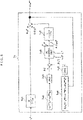
- Fig. 2 illustrates a block of the d-axis secondary magnetic flux estimation computation unit 7, which is a feature of the present embodiment.
- LPF Low Pass Filter
- gain is mutual inductance M and a time constant is a secondary time constant T 2
- a time constant is a secondary time constant T 2
- the d-axis current command value i d * is input to the LPF 71
- the LPF 71 computes a d-axis secondary magnetic flux command value ⁇ 2d *.
- a first active power computation unit 72 computes first active power P c according to (Equation 8) using the d-axis and q-axis voltage command values v dc ** and v qc ** and the current detection values i dc and i qc .
- P c v dc ⁇ ⁇ i dc + v qc ⁇ ⁇ i qc
- an output of the first active power computation unit 72 is passed through an absolute value computation unit 73 to compute the absolute value
- a second active power computation unit 74 computes second active power P c ⁇ according to (Equation 9) using the d-axis and q-axis current command values i d * and i q *, the output frequency command value ⁇ 1 *, R1, M, and L 2 which are electric circuit constants of the induction motor 1, and the d-axis secondary magnetic flux estimated value ⁇ 2d **.
- P c ⁇ R 1 ⁇ i d ⁇ 2 + i q ⁇ 2 + ⁇ 1 ⁇ M ⁇ / L 2 ⁇ ⁇ 2 d ⁇ ⁇ i d ⁇
- an output of the second active power computation unit 74 is passed through an absolute value computation unit 75 to compute the absolute value
- a PI control unit 76 performs P (proportional) control and I (integral) control so that the absolute value
- a LPF 77 has gain with a time constant of T, the secondary magnetic flux command correction value ⁇ 2d0 * is input to the LPF 77, and the LPF 77 outputs a d-axis secondary magnetic flux command correction value ⁇ 2d *.
- This figure is a simulation result when there is an error of +20% in a set value L ⁇ * of the leakage inductance included in a computation formula of the d-axis and q-axis voltage command values v dc ** and v dc ** shown in (Equation 2) and a computation formula of the frequency estimated value (speed estimated value) ⁇ r ⁇ shown in (Equation 5).
- a vertical axis in an upper part indicates the load torque T L (N ⁇ m)
- a vertical axis in a middle part indicates the frequency estimated value ⁇ r ⁇ (Hz) and the frequency ⁇ r (Hz) of the induction motor
- a vertical axis in a lower part indicates the d-axis secondary magnetic flux ⁇ 2d (p.u) and a command value ⁇ 2d * (p.u) thereof
- a horizontal axis indicates time (seconds).
- the ramp-shaped load torque T L starts from point A in the figure and becomes twice the rated torque (100%) torque at point B in the figure, and a state of applying 200% torque is kept from the right side of point B. It can be seen that the frequency ⁇ r of the induction motor is faster than the frequency command value ⁇ r * of 30 Hz.
- the frequency estimated value ⁇ r ⁇ is about 30Hz
- the output frequency command value ⁇ 1 * is calculated by (Equation 6).
- a slip error ⁇ s of the induction motor becomes ( ⁇ s - ⁇ s ⁇ ). Due to this slip error ⁇ s , the d-axis secondary magnetic flux ⁇ 2d increases.
- the control characteristic characteristic of the velocity ⁇
- the first active power P c not including information of the leakage inductance L ⁇ which is an electric circuit constant, is computed from (Equation 8) using the d-axis voltage command value v dc ** and the q-axis voltage command value v qc ** as the voltage information of the induction motor, and the d-axis current detection value i dc and the q-axis current detection value i qc as the current information of the induction motor.
- the second active power P c ⁇ not including information of the leakage inductance L ⁇ is computed by (Equation 9) using the d-axis current command value i d *, the q-axis current command value i q *, the output frequency command value ⁇ 1 *, the electric circuit constants R 1 , M, and L 2 of the induction motor, and the d-axis secondary magnetic flux estimated value ⁇ 2d **.
- the control characteristic can be improved by estimating ⁇ 2d ** so that the absolute value
- the control characteristic in the first embodiment is illustrated in Fig. 4 .
- a horizontal axis and a vertical axis are the same as those of Fig. 3 .
- the d-axis secondary magnetic flux estimation computation unit 7 is operated to apply the same load torque T L as that of Fig. 3 . Since the d-axis secondary magnetic flux ⁇ 2d is estimated with high accuracy ( ⁇ 2d ⁇ ⁇ 2d **), it can be seen that the frequency estimated value ⁇ r ⁇ almost matches the frequency ⁇ r of the induction motor, and the effect of the present embodiment is clear.
- the gains (K p and K i ) of the proportional control and the integral control are set to fixed values.
- the gains may be changed according to the output frequency command value ⁇ 1 * or the q-axis current command value iq*.
- Reference symbol 7a of Fig. 5 corresponds to the d-axis secondary magnetic flux estimation computation unit 7.
- Reference symbols 7a1, 7a2, 7a3, 7a4, 7a5, and 7a7 of Fig. 5 are the same as the LPF 71, the first active power computation unit 72, the absolute value computation unit 73, the second active power computation unit 74, the absolute value computation unit 75, and LPF 77 of Fig. 2 , respectively.
- a PI control unit 7a6 of Fig. 5 by changing the gains (K p and K i ) of the proportional control and the integral control in approximately proportion to the magnitude of the output frequency command value ⁇ 1 * or the q-axis current command value i q *, the absolute value
- a voltage detector 21 and a current detector 22 are attached to a power conversion device 20 that drives the induction motor 1, and an encoder 23 is attached to a shaft of the induction motor 1.
- Three-phase AC voltage detection values (v uc , v vc , and v wc ), which are outputs of the voltage detector 21, three-phase AC current detection values (i uc , i vc , and i wc ), and a position ⁇ , which is an output of the encoder, are input to a vector voltage/current component computation unit 24 to compute vector voltage components v dc and v qc , vector current components i dc and i qc , and a detection value ⁇ r , which is a derivative of the position ⁇ .
- the d-axis secondary magnetic flux estimated value ⁇ 2d ⁇ is computed using (Equation 11).
- the frequency estimated value ⁇ r ⁇ is computed.
- the frequency ⁇ r may be detected by attaching the encoder to the induction motor. Since the d-axis secondary magnetic flux can be estimated with high accuracy, a highly accurate control characteristic can be realized by correcting the slip command value.
- Fig. 7 is a configuration diagram of a d-axis secondary magnetic flux estimation computation unit in the second embodiment.
- the configuration other than the d-axis secondary magnetic flux estimation computation unit is the same as that in the first embodiment.
- the first active power P c is computed from the d-axis and q-axis voltage command values v dc ** and v qc ** and the current detection values i dc and i qc .
- the active power P c is computed using an amplitude value V 1 * of a voltage command of a three-phase AC as voltage information of the induction motor, an amplitude value ii of current detection as current information of the induction motor, and a cosine signal of a phase ⁇ vi .
- Reference symbol 7b of Fig. 7 corresponds to the d-axis secondary magnetic flux estimation computation unit 7 of Fig. 2 .
- reference symbols 7bl, 7b3, 7b4, 7b5, 7b6, and 7b7 of Fig. 7 are the same as the LPF 71, the absolute value computation unit 73, the second active power computation unit 74, the absolute value computation unit 75, the PI control unit 76, and LPF 77 of Fig. 2 , respectively.
- a first active power computation unit 7b2 in a first active power computation unit 7b2, the amplitude value V 1 * of the voltage command of the three-phase AC is obtained from (Equation 12), the amplitude value i 1 of the current detection value is obtained from (Equation 13), the phase ⁇ vi is obtained from (Equation 14), and the active power P c is computed using (Equation 15).
- a highly accurate control characteristic can be realized as in the first embodiment even when the present embodiment is used.
- the gains (K p and K i ) of the proportional control and the integral control can be changed in approximately proportion to the magnitude of the output frequency command value ⁇ 1 * or the q-axis current command value i q *. In this way, it is possible to realize a highly accurate control characteristic in a shorter time even from a low speed range to a high speed range and from a light load to a heavy load.
- Fig. 8 is a configuration diagram of a d-axis secondary magnetic flux estimation computation unit in a third embodiment.
- the configuration other than the d-axis secondary magnetic flux estimation computation unit is the same as that in the first embodiment.
- the first active power P c is computed from the d-axis and q-axis voltage command values v dc ** and v qc ** and the current detection values i dc and i qc .
- the active power P c is computed using a DC voltage value E DC of the DC power supply 3 that supplies a DC voltage to the power converter 2 as voltage information of the induction motor and a DC current value I DC supplied from the DC power supply 3 as current information of the induction motor.
- Reference symbol 7c of Fig. 8 corresponds to the d-axis secondary magnetic flux estimation computation unit 7 of Fig. 2 .
- reference symbols 7c1, 7c3, 7c4, 7c5, 7c6, and 7c7 of Fig. 7 are the same as the LPF 71, the absolute value computation unit 73, the second active power computation unit 74, the absolute value computation unit 75, the PI control unit 76, and LPF 77 of Fig. 2 , respectively.
- the gains (K p and K i ) of the proportional control and the integral control can be changed in approximately proportion to the magnitude of the output frequency command value ⁇ 1 * or the q-axis current command value i q *.
- Fig. 9 is a configuration diagram of a d-axis secondary magnetic flux estimation computation unit in a fourth embodiment.
- the configuration other than the d-axis secondary magnetic flux estimation computation unit is the same as that in the first embodiment.
- two pieces of active power information are used.
- two pieces of reactive power information are used.
- Reference symbol 7d of Fig. 9 corresponds to the d-axis secondary magnetic flux estimation computation unit 7 of Fig. 2 .
- reference symbols 7dl, 7d3, 7d5, 7d6, and 7d7 of Fig. 7 are the same as the LPF 71, the absolute value computation unit 73, the absolute value computation unit 75, the PI control unit 76, and LPF 77 of Fig. 2 , respectively.
- a first reactive power computation unit 7d2 computes first reactive power Q c according to (Equation 17) using the d-axis voltage command value v dc ** and q-axis voltage command value v qc ** as voltage information of the induction motor and the current detection values i dc and i qc as current information of the induction motor.
- Q c v d c **i qc ⁇ v qc **i dc
- an output of the first reactive power computation unit 7d2 is passed through an absolute value computation unit 7d3 to compute the absolute value
- a second reactive power computation unit 7d4 computes second reactive power Q c ⁇ according to (Equation 18) using the d-axis and q-axis current command values i d * and i q *, the output frequency command value ⁇ 1 *, R1, M, and L 2 which are electric circuit constants of the induction motor 1, and the d-axis magnetic flux estimated value ⁇ 2d **.
- Q c ⁇ ⁇ ⁇ 1 * L ⁇ * i d ⁇ 2 + i q ⁇ 2 ⁇ ⁇ 1 * M* / L 2 * ⁇ 2 d **i d *
- an output of the second reactive power computation unit 7d4 is passed through an absolute value computation unit 7d5 to compute the absolute value
- a PI control unit 7d6 performs P (proportional) + I (integral) control so that the absolute value
- a LPF 7d7 has gain with a time constant of T, the d-axis secondary magnetic flux command correction value ⁇ 2d0 * is input to the LPF 7d7, and the LPF 7d7 computes a d-axis secondary magnetic flux command correction value ⁇ 2d *.
- the d-axis secondary magnetic flux estimated value ⁇ 2d ** is computed according to (Equation 10).
- the gains (K p and K i ) of the proportional control and the integral control can be changed in approximately proportion to the magnitude of the output frequency command value ⁇ 1 * or the q-axis current command value i q *. In this way, it is possible to realize a highly accurate control characteristic in a shorter time even from a low speed range to a high speed range and from a light load to a heavy load.
- Fig. 10 is a configuration diagram of a d-axis secondary magnetic flux estimation computation unit in a fifth embodiment.
- the configuration other than the d-axis secondary magnetic flux estimation computation unit is the same as that in the first embodiment.
- first reactive power Q c is computed from the d-axis and q-axis voltage command values v dc ** and v qc ** and the current detection values i dc and i qc .
- the reactive power Q c is computed using an amplitude value V 1 * of a voltage command of a three-phase AC as voltage information of the induction motor, an amplitude value ii of current detection as current information of the induction motor, and a phase ⁇ vi .
- Reference symbol 7e of Fig. 10 corresponds to the d-axis secondary magnetic flux estimation computation unit 7d of Fig. 9 .
- reference symbols 7e1, 7e3, 7e4, 7e5, 7e6, and 7e7 of Fig. 10 are the same as the LPF 7dl, the absolute value computation unit 7d3, the second reactive power computation unit 7d4, the absolute value computation unit 7d5, the PI control unit 7d6, and LPF 7d7 of Fig. 9 , respectively.
- the gains (K p and K i ) of the proportional control and the integral control can be changed in approximately proportion to the magnitude of the output frequency command value ⁇ 1 * or the q-axis current command value i q *. In this way, it is possible to realize a highly accurate control characteristic in a shorter time even from a low speed range to a high speed range and from a light load to a heavy load.
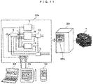
- Fig. 11 is a configuration diagram of a system including a power conversion device and an induction motor according to a sixth embodiment.
- the present embodiment is an application of the present embodiment to an induction motor drive system.
- an induction motor 1 a coordinate transformation unit 5, a speed control computation unit 6, a d-axis secondary magnetic flux estimation computation unit 7, a vector control computation unit 8, and a frequency/phase estimation computation unit 9 have the same configuration as that of Fig. 1 .
- the induction motor 1, which is a component of Fig. 1 is driven by a power conversion device 20.
- the power conversion device 20 is divided into software 20a and hardware.
- the coordinate transformation unit 5, the speed control computation unit 6, the d-axis secondary magnetic flux estimation computation unit 7, the vector control computation unit 8, the frequency/phase estimation computation unit 9, and the coordinate transformation unit 10 of Fig. 1 are the software 20a.
- the same parts of the software 20a of Fig. 11 as those of Fig. 1 are partially omitted.
- the power converter 2, the DC power supply 3, and the current detector 4 of Fig. 1 are mounted as hardware. Further, it is possible to set predetermined proportional gain 31 and predetermined integral gain 32 of the software 20a in a recording unit of the control unit or change recorded gain by a higher-level device such as a digital operator 20b, a personal computer 28, a tablet PC 29, or a smartphone 30 performing operation or display of the power conversion device 20.
- a higher-level device such as a digital operator 20b, a personal computer 28, a tablet PC 29, or a smartphone 30 performing operation or display of the power conversion device 20.
- proportional gain Kp1 or integral gain Ki1 of the PI control unit 76 in the d-axis secondary magnetic flux estimation computation unit 7 can be set externally or the gain can be changed.
- the predetermined proportional gain 31 and the predetermined integral gain 32 may be set on a fieldbus of a programmable logic controller, a local area network connected to a computer, or a control device.
- any one of the second to fifth embodiments may be used.
- the voltage correction values ⁇ v dc and ⁇ v qc are created from the current command values i d * and i q * and the current detection values i dc and i qc , and computation shown in (Equation 3) of adding the voltage correction values and a voltage reference value of vector control is performed.
- K pd1 denotes proportional gain of d-axis current control
- K id1 denotes integral gain of d-axis current control
- K pq1 denotes proportional gain of q-axis current control
- K iql denotes integral gain of q-axis current control
- T d denotes d-axis electrical time constant (L ⁇ /R)
- T q denotes q-axis electrical time constant (L ⁇ /R).
- a voltage correction value ⁇ v d_p * of a d-axis proportional computation component, a voltage correction value ⁇ v d_i * of a d-axis integral computation component, a voltage correction value ⁇ v q_p * of a q-axis proportional computation component, and a voltage correction value ⁇ v q_i * of a q-axis integral computation component used for vector control computation may be computed by (Equation 22) from the current command values i d ** and i q * and the current detection values i dc and i qc , and vector control computation shown in (Equation 23) may be performed using the output frequency command value ⁇ 1 * and the electric circuit constants of the induction motor 1.
- K pd2 denotes proportional gain of d-axis current control
- K id2 denotes integral gain of d-axis current control
- K pq2 denotes proportional gain of q-axis current control
- K iq2 denotes integral gain of q-axis current control
- an output frequency command value ⁇ 1 ** shown in (Equation 24) and vector control computation shown in (Equation 25) may be performed using the d-axis current command value i d *, a primary delay signal i qctd of the q-axis current detection value i qc , the frequency command value ⁇ r *, and the electric circuit constants of the induction motor 1.
- i qctd is a signal obtained by passing i qc through a primary delay filter.
- K pq3 is proportional gain of current control
- K iq3 is integral gain of current control
- the frequency estimated value is computed according to (Equation 5) or (Equation 26).
- equation 5 the frequency estimated value is computed according to (Equation 5) or (Equation 26).
- a switching element included in the power converter 2 it is possible to use a Si (silicon) semiconductor element, or a wide bandgap semiconductor element of SiC (Silicon Carbide), GaN (Gallium Nitride), etc.
Landscapes
- Engineering & Computer Science (AREA)
- Power Engineering (AREA)
- Control Of Ac Motors In General (AREA)
Abstract
Description
- The present invention relates to a power conversion device that drives an induction motor.
- As a highly accurate control method for an induction motor, as described in
Patent Document 1, there is a description of a technology for estimating a stator magnetic flux vector of an induction motor based on a difference between an output voltage from a power conversion unit to an induction motor and the amount of voltage drop caused by a winding resistance of an electric motor. - Patent Document 1:
JP 2016-32364 A - In the technology described in
Patent Document 1, the magnetic flux vector is estimated using a rest coordinate system α and β. At each axis component of αβ, the magnetic flux vector changes into a sine wave shape. Therefore, in a high-speed range, a value of the amplitude of the sine wave cannot be accurately detected unless a sampling period for detecting the change in the sine wave is sufficiently short. However, since there is a limit to the sampling period, it is difficult to improve the accuracy of magnetic flux estimation in a high-speed range exceeding the limit. - In
Patent Document 1, it is considered that a speed command value and an actual rotation speed of the induction motor deviate from each other due to insufficient accuracy of magnetic flux estimation, resulting in a poor speed characteristic. Further, when the magnetic flux is estimated in a high-speed range, there is a problem that the speed characteristic deteriorates due to an error of an electric circuit constant. - An object of the invention is to provide a power conversion device that prevents deterioration of a speed characteristic in a high-speed range.
- A preferred example of the invention is a power conversion device including
- a power converter including a switching element, and
- a control unit for controlling the power converter from voltage information and current information of an induction motor,
- in which the control unit
- computes first power information computed from voltage information and current information of the induction motor,
- computes second power information from an electric circuit constant, a current command value, an output frequency command value, and a magnetic flux estimated value of the induction motor, and
- computes the magnetic flux estimated value so that the second power information follows the first power information.
- According to the invention, it is possible to prevent deterioration of a speed characteristic in a high-speed range.
-
-
Fig. 1 is a configuration diagram of a power conversion device in a first embodiment. -
Fig. 2 is a configuration diagram of a d-axis secondary magnetic flux estimation computation unit in the first embodiment. -
Fig. 3 is a diagram illustrating a control characteristic when a comparative example is used. -
Fig. 4 is a diagram illustrating a control characteristic when the first embodiment is used. -
Fig. 5 is a configuration diagram of a d-axis secondary magnetic flux estimation computation unit as a modification of the first embodiment. -
Fig. 6 is a configuration diagram for confirming manifestation in the first embodiment. -
Fig. 7 is a configuration diagram of a d-axis secondary magnetic flux estimation computation unit in a second embodiment. -
Fig. 8 is a configuration diagram of a d-axis secondary magnetic flux estimation computation unit in a third embodiment. -
Fig. 9 is a configuration diagram of a d-axis secondary magnetic flux estimation computation unit in a fourth embodiment. -
Fig. 10 is a configuration diagram of a d-axis secondary magnetic flux estimation computation unit in a fifth embodiment. -
Fig. 11 is a configuration diagram including a power conversion device and an induction motor in a sixth embodiment. - Hereinafter, embodiments will be described in detail with reference to the drawings.
-
Fig. 1 is a configuration diagram of a power conversion device in a first embodiment. Aninduction motor 1 generates torque by magnetic flux generated by a current of a magnetic flux axis (d-axis) component and a current of a torque axis (q-axis) component orthogonal to a magnetic flux axis. - The
power converter 2 includes a semiconductor element as a switching element. The power converter 2 inputs three-phase AC voltage command values vu*, vv*, and vw*, and outputs voltage values proportional to the three-phase AC voltage command values vu*, vv*, and vw*. An output voltage value and an output frequency value of theinduction motor 1 are changed based on an output of thepower converter 2. An IGBT may be used as the switching element. - A DC power supply 3 supplies a DC voltage and a DC current to the
power converter 2. - A current detector 4 outputs iuc, ivc, and iwc, which are detection value of three-phase alternating currents iu, iv, and iw of the
induction motor 1. Further, current detector 4 may detect AC currents of two of the three phases of theinduction motor 1, for example, the u-phase and the w-phase, and the v-phase AC current may be obtained as iv = -(iu + iw) from an AC condition (iu + iv + iw = 0). In the present embodiment, the current detector 4 is provided inside the power conversion device. However, the current detector 4 may be provided outside the power conversion device. - The control unit includes a
coordinate transformation unit 5, a speedcontrol computation unit 6, a d-axis secondary magnetic fluxestimation computation unit 7, a vectorcontrol computation unit 8, a frequency/phaseestimation computation unit 9, and acoordinate transformation unit 10 described below. Then, the control unit controls thepower converter 2. - The control unit includes semiconductor integrated circuits (arithmetic control means) such as a microcomputer and a DSP (Digital Signal Processor). A part or whole of control unit can be configured by hardware such as an ASIC (Application Specific Integrated Circuit) or an FPGA (Field Programmable Gate Array).
- Next, each component of the control unit that controls the
power converter 2 will be described. - The
coordinate transformation unit 5 outputs a d-axis current detection value idc and a q-axis current detection value iqc from the AC current detection values iuc, ivc, and iwc of the three-phase alternating currents iu, iv, and iw and a phase computation value θdc. - The speed
control computation unit 6 outputs a q-axis current command value iq* computed based on a frequency command value ωr* and a frequency estimated value ωr^. - The d-axis secondary magnetic flux
estimation computation unit 7 outputs a d-axis magnetic flux estimated value φ2d** computed based on d-axis and q-axis voltage command values vdc** and vqc**, current detection values idc and iqc, current command values id* and iq*, and an output frequency command value ω1*. - The vector
control computation unit 8 outputs the d-axis and q-axis voltage command values vdc** and vqc** computed based on the d-axis secondary magnetic flux estimated value φ2d**, the d-axis and q-axis current command values id* and iq*, the current detection values idc and iqc, and the output frequency command value ω1*. - The frequency/phase
estimation computation unit 9 outputs the frequency estimated value ωr^, the output frequency command value ω1*, and the phase computation value θdc computed based on the q-axis voltage command value vqc**, the d-axis current command value id*, the q-axis current command value iq*, the current detection value iqc, and the d-axis secondary magnetic flux estimated value φ2d**. - The
coordinate transformation unit 10 outputs three-phase AC voltage command values vu*, vv*, and vw* from the d-axis voltage command value vdc**, the q-axis voltage command value vqc**, and the phase computation value θdc. - First, a basic operation of sensorless vector control when the d-axis secondary magnetic flux
estimation computation unit 7 is used will be described. - The speed
control computation unit 6 computes a q-axis current command value iq*, which is a torque current command, according to (Equation 1) by proportional control and integral control so that the frequency estimated value ωr^ follows the frequency command value ωr*.
[Equation 1]
- Here, Ksp denotes proportional gain of speed control, and Ksi denotes integral gain of speed control.
- First, the vector
control computation unit 8 outputs d-axis and q-axis voltage command values vds* and vqc* according to (Equation 2) using the d-axis secondary magnetic flux estimated value φ2d**, the d-axis and q-axis current command values id* and iq*, and the output frequency command value ω1*.
[Equation 2]
- Here, Tacr denotes a time constant corresponding to a current control delay, R1 denotes a primary resistance value, Lσ denotes a leakage inductance value, M denotes a mutual inductance value, and L2 denotes a secondary side inductance value.
- Second, d-axis and q-axis voltage correction values Δvdc and Δvqc are computed according to (Equation 3) by proportional control and integral control so that the current detection values idc and iqc of each component follow the d-axis and q-axis current command values id* and iq*.
[Equation 3]
- Here, Kpd denotes proportional gain of d-axis current control, Kid denotes integral gain of d-axis current control, Kpq denotes proportional gain of q-axis current control, and Kiq denotes integral gain of q-axis current control.
- Further, according to (Equation 4), the d-axis and q-axis voltage command values vdc** and vdc** are computed.
[Equation 4]
- Based on the q-axis voltage command value vqc**, the d-axis current command value id*, the q-axis current command value iq*, the current detection value iqc, and the d-axis secondary magnetic flux estimated value φ2d**, the frequency/phase
estimation computation unit 9 computes the frequency estimated value ωr^ according to (Equation 5), computes the output frequency command value ω1* according to (Equation 6), and computes the phase computation value θdc according to (Equation 7), respectively.
[Equation 5]
- Here, R* denotes a set value obtained by adding primary resistance and secondary resistance, and Tobs denotes a time constant for speed estimation.
[Equation 6]
[Equation 7]
-
Fig. 2 illustrates a block of the d-axis secondary magnetic fluxestimation computation unit 7, which is a feature of the present embodiment. - In an LPF (Low Pass Filter) 71, gain is mutual inductance M and a time constant is a secondary time constant T2, the d-axis current command value id* is input to the
LPF 71, and theLPF 71 computes a d-axis secondary magnetic flux command value φ2d*. - A first active
power computation unit 72 computes first active power Pc according to (Equation 8) using the d-axis and q-axis voltage command values vdc** and vqc** and the current detection values idc and iqc.
[Equation 8]
- To support both power running/regenerative operation modes, an output of the first active
power computation unit 72 is passed through an absolutevalue computation unit 73 to compute the absolute value |Pc| of first active power Pc. - A second active
power computation unit 74 computes second active power Pc^ according to (Equation 9) using the d-axis and q-axis current command values id* and iq*, the output frequency command value ω1*, R1, M, and L2 which are electric circuit constants of theinduction motor 1, and the d-axis secondary magnetic flux estimated value φ2d**.
[Equation 9]
- To support both power running/regenerative operation modes, an output of the second active
power computation unit 74 is passed through an absolutevalue computation unit 75 to compute the absolute value |Pc^| of second active power Pc^. - A
PI control unit 76 performs P (proportional) control and I (integral) control so that the absolute value |Pc^| of the second active power Pc^ follows the absolute value |Pc| of the first active power Pc, and computes a d-axis secondary magnetic flux command correction value Δφ2d0*. - A
LPF 77 has gain with a time constant of T, the secondary magnetic flux command correction value Δφ2d0* is input to theLPF 77, and theLPF 77 outputs a d-axis secondary magnetic flux command correction value Δφ2d*. Using Δφ2d* and the d-axis secondary magnetic flux command value φ2d*, the d-axis secondary magnetic flux estimated value φ2d** is computed according to (Equation 10).
[Equation 10]
- Next, a principle that the present embodiment has a high-precision control characteristic will be described.
-
Fig. 3 illustrates a control characteristic as a comparative example not using the d-axis secondary magnetic flux estimation computation unit 7 (Δφ2d* = 0). This figure is a simulation result when there is an error of +20% in a set value Lσ* of the leakage inductance included in a computation formula of the d-axis and q-axis voltage command values vdc** and vdc** shown in (Equation 2) and a computation formula of the frequency estimated value (speed estimated value) ωr^ shown in (Equation 5). - A vertical axis in an upper part indicates the load torque TL (N·m), a vertical axis in a middle part indicates the frequency estimated value ωr^ (Hz) and the frequency ωr (Hz) of the induction motor, a vertical axis in a lower part indicates the d-axis secondary magnetic flux φ2d (p.u) and a command value φ2d* (p.u) thereof, and a horizontal axis indicates time (seconds).
- The ramp-shaped load torque TL starts from point A in the figure and becomes twice the rated torque (100%) torque at point B in the figure, and a state of applying 200% torque is kept from the right side of point B. It can be seen that the frequency ωr of the induction motor is faster than the frequency command value ωr* of 30 Hz.
- Meanwhile, the frequency estimated value ωr^ is about 30Hz, and the output frequency command value ω1* is calculated by (Equation 6). Thus, an estimated error of the frequency is Δω = (ωr - ωr^), and a slip error Δωs of the induction motor becomes (ωs - ωs^). Due to this slip error Δωs, the d-axis secondary magnetic flux φ2d increases. Then, the control characteristic (characteristic of the velocity ω) deteriorates depending on the set value Lσ* of the leakage inductance. That is, there is a problem that the rotation speed of the induction motor deviates from the speed command value, resulting in deterioration of the speed characteristic.
- In the present embodiment, the first active power Pc not including information of the leakage inductance Lσ, which is an electric circuit constant, is computed from (Equation 8) using the d-axis voltage command value vdc** and the q-axis voltage command value vqc** as the voltage information of the induction motor, and the d-axis current detection value idc and the q-axis current detection value iqc as the current information of the induction motor.
- In addition, the second active power Pc^ not including information of the leakage inductance Lσ is computed by (Equation 9) using the d-axis current command value id*, the q-axis current command value iq*, the output frequency command value ω1*, the electric circuit constants R1, M, and L2 of the induction motor, and the d-axis secondary magnetic flux estimated value φ2d**.
- The control characteristic can be improved by estimating φ2d** so that the absolute value |Pc^| of Pc^ follows the absolute value |Pc| of Pc and using an estimated value φ2d^ for the vector
control computation unit 8 and the frequency/phaseestimation computation unit 9. - The control characteristic in the first embodiment is illustrated in
Fig. 4 . InFig. 4 , a horizontal axis and a vertical axis are the same as those ofFig. 3 . The d-axis secondary magnetic fluxestimation computation unit 7 is operated to apply the same load torque TL as that ofFig. 3 . Since the d-axis secondary magnetic flux φ2d is estimated with high accuracy (φ2d ≈ φ2d**), it can be seen that the frequency estimated value ωr^ almost matches the frequency ωr of the induction motor, and the effect of the present embodiment is clear. - In addition, in the above embodiment, in the d-axis secondary magnetic flux
estimation computation unit 7, the gains (Kp and Ki) of the proportional control and the integral control are set to fixed values. However, as illustrated inFig. 5 , the gains may be changed according to the output frequency command value ω1* or the q-axis current command value iq*. -
Reference symbol 7a ofFig. 5 corresponds to the d-axis secondary magnetic fluxestimation computation unit 7. Reference symbols 7a1, 7a2, 7a3, 7a4, 7a5, and 7a7 ofFig. 5 are the same as theLPF 71, the first activepower computation unit 72, the absolutevalue computation unit 73, the second activepower computation unit 74, the absolutevalue computation unit 75, andLPF 77 ofFig. 2 , respectively. - In a PI control unit 7a6 of
Fig. 5 , by changing the gains (Kp and Ki) of the proportional control and the integral control in approximately proportion to the magnitude of the output frequency command value ω1* or the q-axis current command value iq*, the absolute value |Pc| of the first active power Pc changes to the absolute value |Pc^| of the second active power Pc^ according to the frequency or the current value. That is, it is possible to realize a highly accurate control characteristic in a shorter time even from a low speed range to a high speed range and from a light load to a heavy load. - Here, a verification method when the present embodiment is adopted will be described with reference to
Fig. 6 . Avoltage detector 21 and acurrent detector 22 are attached to apower conversion device 20 that drives theinduction motor 1, and anencoder 23 is attached to a shaft of theinduction motor 1. - Three-phase AC voltage detection values (vuc, vvc, and vwc), which are outputs of the
voltage detector 21, three-phase AC current detection values (iuc, ivc, and iwc), and a position θ, which is an output of the encoder, are input to a vector voltage/currentcomponent computation unit 24 to compute vector voltage components vdc and vqc, vector current components idc and iqc, and a detection value ωr, which is a derivative of the position θ. - In an
observation unit 25 of a waveform of each part, the d-axis secondary magnetic flux estimated value φ2d^ is computed using (Equation 11).
[Equation 11]
- It becomes clear that when the magnitude of the leakage inductance Lσ* set in the
power converter 2 is changed, the magnitude of φ2d^ is changed, and when the detection value ωr almost matches the command value, the present embodiment is adopted. - Note that in the present embodiment, the frequency estimated value ωr^ is computed. However, the frequency ωr may be detected by attaching the encoder to the induction motor. Since the d-axis secondary magnetic flux can be estimated with high accuracy, a highly accurate control characteristic can be realized by correcting the slip command value.
-
Fig. 7 is a configuration diagram of a d-axis secondary magnetic flux estimation computation unit in the second embodiment. In the present embodiment, the configuration other than the d-axis secondary magnetic flux estimation computation unit is the same as that in the first embodiment. In the first embodiment, the first active power Pc is computed from the d-axis and q-axis voltage command values vdc** and vqc** and the current detection values idc and iqc. - In the second embodiment, the active power Pc is computed using an amplitude value V1* of a voltage command of a three-phase AC as voltage information of the induction motor, an amplitude value ii of current detection as current information of the induction motor, and a cosine signal of a phase θvi.
-
Reference symbol 7b ofFig. 7 corresponds to the d-axis secondary magnetic fluxestimation computation unit 7 ofFig. 2 . In addition, reference symbols 7bl, 7b3, 7b4, 7b5, 7b6, and 7b7 ofFig. 7 are the same as theLPF 71, the absolutevalue computation unit 73, the second activepower computation unit 74, the absolutevalue computation unit 75, thePI control unit 76, andLPF 77 ofFig. 2 , respectively. - In
Fig. 7 , in a first active power computation unit 7b2, the amplitude value V1* of the voltage command of the three-phase AC is obtained from (Equation 12), the amplitude value i1 of the current detection value is obtained from (Equation 13), the phase θvi is obtained from (Equation 14), and the active power Pc is computed using (Equation 15).
[Equation 12]
[Equation 13]
[Equation 14]
[Equation 15]
- A highly accurate control characteristic can be realized as in the first embodiment even when the present embodiment is used.
- In addition, in the second embodiment, as in
Fig. 5 , in the PI control unit 7a6, the gains (Kp and Ki) of the proportional control and the integral control can be changed in approximately proportion to the magnitude of the output frequency command value ω1* or the q-axis current command value iq*. In this way, it is possible to realize a highly accurate control characteristic in a shorter time even from a low speed range to a high speed range and from a light load to a heavy load. -
Fig. 8 is a configuration diagram of a d-axis secondary magnetic flux estimation computation unit in a third embodiment. In the present embodiment, the configuration other than the d-axis secondary magnetic flux estimation computation unit is the same as that in the first embodiment. In the first embodiment, the first active power Pc is computed from the d-axis and q-axis voltage command values vdc** and vqc** and the current detection values idc and iqc. - In the third embodiment, the active power Pc is computed using a DC voltage value EDC of the DC power supply 3 that supplies a DC voltage to the
power converter 2 as voltage information of the induction motor and a DC current value IDC supplied from the DC power supply 3 as current information of the induction motor. - Reference symbol 7c of
Fig. 8 corresponds to the d-axis secondary magnetic fluxestimation computation unit 7 ofFig. 2 . In addition, reference symbols 7c1, 7c3, 7c4, 7c5, 7c6, and 7c7 ofFig. 7 are the same as theLPF 71, the absolutevalue computation unit 73, the second activepower computation unit 74, the absolutevalue computation unit 75, thePI control unit 76, andLPF 77 ofFig. 2 , respectively. - In
Fig. 7 , in 7c2, using a DC voltage detection value EDC and a DC current detection value IDC of the power converter, the active power Pc is computed using (Equation 16).
[Equation 16]
- Even when the present embodiment is used, a highly accurate control characteristic can be realized as in the first embodiment.
- In addition, in the third embodiment, as in
Fig. 5 , in the PI control unit 7c6, the gains (Kp and Ki) of the proportional control and the integral control can be changed in approximately proportion to the magnitude of the output frequency command value ω1* or the q-axis current command value iq*. -
Fig. 9 is a configuration diagram of a d-axis secondary magnetic flux estimation computation unit in a fourth embodiment. In the present embodiment, the configuration other than the d-axis secondary magnetic flux estimation computation unit is the same as that in the first embodiment. In the first embodiment, two pieces of active power information are used. However, from the present embodiment, two pieces of reactive power information are used. -
Reference symbol 7d ofFig. 9 corresponds to the d-axis secondary magnetic fluxestimation computation unit 7 ofFig. 2 . In addition, reference symbols 7dl, 7d3, 7d5, 7d6, and 7d7 ofFig. 7 are the same as theLPF 71, the absolutevalue computation unit 73, the absolutevalue computation unit 75, thePI control unit 76, andLPF 77 ofFig. 2 , respectively. - A first reactive power computation unit 7d2 computes first reactive power Qc according to (Equation 17) using the d-axis voltage command value vdc** and q-axis voltage command value vqc** as voltage information of the induction motor and the current detection values idc and iqc as current information of the induction motor.
[Equation 17]
- To support both power running/regenerative operation modes, an output of the first reactive power computation unit 7d2 is passed through an absolute value computation unit 7d3 to compute the absolute value |Qc| of first reactive power Qc.
- A second reactive power computation unit 7d4 computes second reactive power Qc^ according to (Equation 18) using the d-axis and q-axis current command values id* and iq*, the output frequency command value ω1*, R1, M, and L2 which are electric circuit constants of the
induction motor 1, and the d-axis magnetic flux estimated value φ2d**.
[Equation 18]
- To support both power running/regenerative operation modes, an output of the second reactive power computation unit 7d4 is passed through an absolute value computation unit 7d5 to compute the absolute value |Qc^| of second reactive power Qc^.
- A PI control unit 7d6 performs P (proportional) + I (integral) control so that the absolute value |Qc^| of the second reactive power Qc^ follows the absolute value |Qc| of the first reactive power Qc, and computes a d-axis secondary magnetic flux command correction value Δφ2d0*.
- A LPF 7d7 has gain with a time constant of T, the d-axis secondary magnetic flux command correction value Δφ2d0* is input to the LPF 7d7, and the LPF 7d7 computes a d-axis secondary magnetic flux command correction value Δφ2d*. Using Δφ2d* and the d-axis secondary magnetic flux command value φ2d*, the d-axis secondary magnetic flux estimated value φ2d** is computed according to (Equation 10).
- In the present embodiment, by correcting the d-axis secondary magnetic flux command value φ2d* so that the absolute value |Qc^| of the second reactive power Qc^ follows the absolute value |Qc| of the first reactive power Qc, it is possible to realize a highly accurate control characteristic regardless of the power running/regenerative operation mode even when there is an error in a set value R1* of the resistance, which is an electric circuit constant.
- In the fourth embodiment, as in
Fig. 5 , in the PI control unit 7a6, the gains (Kp and Ki) of the proportional control and the integral control can be changed in approximately proportion to the magnitude of the output frequency command value ω1* or the q-axis current command value iq*. In this way, it is possible to realize a highly accurate control characteristic in a shorter time even from a low speed range to a high speed range and from a light load to a heavy load. -
Fig. 10 is a configuration diagram of a d-axis secondary magnetic flux estimation computation unit in a fifth embodiment. In the present embodiment, the configuration other than the d-axis secondary magnetic flux estimation computation unit is the same as that in the first embodiment. In the fourth embodiment, first reactive power Qc is computed from the d-axis and q-axis voltage command values vdc** and vqc** and the current detection values idc and iqc. - In the fifth embodiment, the reactive power Qc is computed using an amplitude value V1* of a voltage command of a three-phase AC as voltage information of the induction motor, an amplitude value ii of current detection as current information of the induction motor, and a phase θvi.
-
Reference symbol 7e ofFig. 10 corresponds to the d-axis secondary magnetic fluxestimation computation unit 7d ofFig. 9 . In addition, reference symbols 7e1, 7e3, 7e4, 7e5, 7e6, and 7e7 ofFig. 10 are the same as the LPF 7dl, the absolute value computation unit 7d3, the second reactive power computation unit 7d4, the absolute value computation unit 7d5, the PI control unit 7d6, and LPF 7d7 ofFig. 9 , respectively. - In
Fig. 10 , in 7e2, the amplitude value V1* of the voltage command of the three-phase AC is computed using (Equation 12), the amplitude value ii of the current detection value is computed using (Equation 13), and the reactive power Qc is computed using a sine signal of a phase θvi by (Equation 19) .
[Equation 19]
- Even when the present embodiment is used, similarly to the fourth embodiment, it is possible to realize a highly accurate control characteristic regardless of both power running/regenerative torque modes even when there is an error in a set value R1* of the resistance.
- In the fifth embodiment, as in
Fig. 5 , in the PI control unit 7e6, the gains (Kp and Ki) of the proportional control and the integral control can be changed in approximately proportion to the magnitude of the output frequency command value ω1* or the q-axis current command value iq*. In this way, it is possible to realize a highly accurate control characteristic in a shorter time even from a low speed range to a high speed range and from a light load to a heavy load. -
Fig. 11 is a configuration diagram of a system including a power conversion device and an induction motor according to a sixth embodiment. The present embodiment is an application of the present embodiment to an induction motor drive system. InFig. 11 , aninduction motor 1, a coordinatetransformation unit 5, a speedcontrol computation unit 6, a d-axis secondary magnetic fluxestimation computation unit 7, a vectorcontrol computation unit 8, and a frequency/phaseestimation computation unit 9 have the same configuration as that ofFig. 1 . - The
induction motor 1, which is a component ofFig. 1 , is driven by apower conversion device 20. Thepower conversion device 20 is divided intosoftware 20a and hardware. The coordinatetransformation unit 5, the speedcontrol computation unit 6, the d-axis secondary magnetic fluxestimation computation unit 7, the vectorcontrol computation unit 8, the frequency/phaseestimation computation unit 9, and the coordinatetransformation unit 10 ofFig. 1 are thesoftware 20a. The same parts of thesoftware 20a ofFig. 11 as those ofFig. 1 are partially omitted. - The
power converter 2, the DC power supply 3, and the current detector 4 ofFig. 1 are mounted as hardware. Further, it is possible to set predeterminedproportional gain 31 and predeterminedintegral gain 32 of thesoftware 20a in a recording unit of the control unit or change recorded gain by a higher-level device such as adigital operator 20b, apersonal computer 28, atablet PC 29, or asmartphone 30 performing operation or display of thepower conversion device 20. - For example, proportional gain Kp1 or integral gain Ki1 of the
PI control unit 76 in the d-axis secondary magnetic fluxestimation computation unit 7 can be set externally or the gain can be changed. - When the present embodiment is applied to the induction motor drive system, a highly accurate control characteristic can be realized in speed sensorless vector control. Further, the predetermined
proportional gain 31 and the predeterminedintegral gain 32 may be set on a fieldbus of a programmable logic controller, a local area network connected to a computer, or a control device. - Further, even though the sixth embodiment is disclosed using the first embodiment, any one of the second to fifth embodiments may be used.
- In the first to fifth embodiments, the voltage correction values Δvdc and Δvqc are created from the current command values id* and iq* and the current detection values idc and iqc, and computation shown in (Equation 3) of adding the voltage correction values and a voltage reference value of vector control is performed.
- It is possible to create intermediate current command values id** and iq** shown in (Equation 20) used for vector control computation from the current command values id* and iq* and the current detection values idc and iqc, and perform vector control computation shown in (Equation 21) using the output frequency command value ω1* and the electric circuit constant of the
induction motor 1.
[Equation 20]
- Here, Kpd1 denotes proportional gain of d-axis current control, Kid1 denotes integral gain of d-axis current control, Kpq1 denotes proportional gain of q-axis current control, Kiql denotes integral gain of q-axis current control, Td denotes d-axis electrical time constant (Lσ/R), and Tq denotes q-axis electrical time constant (Lσ/R).
[Equation 21]
- A voltage correction value Δvd_p* of a d-axis proportional computation component, a voltage correction value Δvd_i* of a d-axis integral computation component, a voltage correction value Δvq_p* of a q-axis proportional computation component, and a voltage correction value Δvq_i* of a q-axis integral computation component used for vector control computation may be computed by (Equation 22) from the current command values id** and iq* and the current detection values idc and iqc, and vector control computation shown in (Equation 23) may be performed using the output frequency command value ω1* and the electric circuit constants of the
induction motor 1.
[Equation 22]
- Here, Kpd2 denotes proportional gain of d-axis current control, Kid2 denotes integral gain of d-axis current control, Kpq2 denotes proportional gain of q-axis current control, and Kiq2 denotes integral gain of q-axis current control.
[Equation 23]
- Further, an output frequency command value ω1** shown in (Equation 24) and vector control computation shown in (Equation 25) may be performed using the d-axis current command value id*, a primary delay signal iqctd of the q-axis current detection value iqc, the frequency command value ωr*, and the electric circuit constants of the
induction motor 1.
[Equation 24]
[Equation 25]
- Here, iqctd is a signal obtained by passing iqc through a primary delay filter.
- In the first to fifth embodiments, the frequency/phase
estimation computation unit 9 computes a frequency estimated value according to (Equation 5). Current control and speed estimation may be used together in q-axis current control. A frequency estimated value ωr^^ is computed as shown in (Equation 26).
[Equation 26]
- Here, Kpq3 is proportional gain of current control, and Kiq3 is integral gain of current control.
- Further, in the frequency/phase
estimation computation unit 9, the frequency estimated value is computed according to (Equation 5) or (Equation 26). However, it is possible to attach an encoder to theinduction motor 1 and compute a frequency detection value from an encoder signal. - Note that in the first to sixth embodiments, as a switching element included in the
power converter 2, it is possible to use a Si (silicon) semiconductor element, or a wide bandgap semiconductor element of SiC (Silicon Carbide), GaN (Gallium Nitride), etc. -
- 1
- Induction motor
- 2
- Power converter
- 3
- DC power supply
- 4
- Current detector
- 5
- Coordinate transformation unit
- 6
- Speed control computation unit
- 7
- d-axis secondary magnetic flux estimation computation unit
- 8
- Vector control computation unit
- 9
- Frequency/phase estimation computation unit
- 10
- Coordinate transformation unit
Claims (12)
- A power conversion device comprising:a power converter including a switching element; anda control unit for controlling the power converter from voltage information and current information of an induction motor,wherein the control unitcomputes first power information computed from voltage information and current information of the induction motor,computes second power information from an electric circuit constant, a current command value, an output frequency command value, and a magnetic flux estimated value of the induction motor, andcomputes the magnetic flux estimated value so that the second power information follows the first power information.
- The power conversion device according to claim 1, wherein the first power information and the second power information are active power.
- The power conversion device according to claim 2,wherein the control unitcomputes the first power information from d-axis and q-axis voltage command values and d-axis and q-axis detection currents,computes the second power information from the electric circuit constant, d-axis and q-axis current command values, the output frequency command value, and a d-axis magnetic flux estimated value of the induction motor, andcomputes the d-axis magnetic flux estimated value so that the second power information follows the first power information.
- The power conversion device according to claim 2,wherein the control unitcomputes the first power information from a voltage command value of a three-phase AC and an amplitude value of a current detection value,computes the second power information from the electric circuit constant, d-axis and q-axis current command values, the output frequency command value, and a d-axis magnetic flux estimated value of the induction motor, andcomputes the d-axis magnetic flux estimated value so that the second power information follows the first power information.
- The power conversion device according to claim 2,wherein the control unitcomputes the first power information from a DC voltage value and a DC current value of the power converter,computes the second power information from the electric circuit constant, d-axis and q-axis current command values, the output frequency command value, and a d-axis magnetic flux estimated value of the induction motor, andcomputes the d-axis magnetic flux estimated value so that the second power information follows the first power information.
- The power conversion device according to claim 1, wherein the first power information and the second power information are reactive power.
- The power conversion device according to claim 6,wherein the control unitcomputes the first power information from d-axis and q-axis voltage command values and d-axis and q-axis detection currents,computes the second power information from the electric circuit constant, d-axis and q-axis current command values, the output frequency command value, and a d-axis magnetic flux estimated value of the induction motor, andcomputes the d-axis magnetic flux estimated value so that the second power information follows the first power information.
- The power conversion device according to claim 6,wherein the control unitcomputes the first power information from a voltage command value of a three-phase AC and an amplitude value of a current detection value,computes the second power information from the electric circuit constant, d-axis and q-axis current command values, the output frequency command value, and a d-axis magnetic flux estimated value of the induction motor, andcomputes the d-axis magnetic flux estimated value so that the second power information follows the first power information.
- The power conversion device according to claim 1, wherein the control unit computes the magnetic flux estimated value by proportional control and integral control so that a deviation between the first power information and the second power information becomes zero.
- The power conversion device according to claim 9, wherein control gains of the proportional control and the integral control are corrected based on at least one of the output frequency command value or a q-axis current command value of the induction motor.
- The power conversion device according to claim 1, wherein control gain set in proportional control or integral control is set in a recording unit from a digital operator, a personal computer, a tablet PC, or a smartphone device, or set control gain is changed.
- The power conversion device according to claim 1, further comprising:a vector control computation unit for outputting a voltage command value based on the magnetic flux estimated value; anda frequency/phase estimation computation unit for outputting the output frequency command value and a frequency estimated value based on the magnetic flux estimated value.
Applications Claiming Priority (2)
| Application Number | Priority Date | Filing Date | Title |
|---|---|---|---|
| JP2019220626A JP7287885B2 (en) | 2019-12-05 | 2019-12-05 | power converter |
| PCT/JP2020/034294 WO2021111695A1 (en) | 2019-12-05 | 2020-09-10 | Power conversion device |
Publications (2)
| Publication Number | Publication Date |
|---|---|
| EP4072005A1 true EP4072005A1 (en) | 2022-10-12 |
| EP4072005A4 EP4072005A4 (en) | 2023-12-06 |
Family
ID=76220761
Family Applications (1)
| Application Number | Title | Priority Date | Filing Date |
|---|---|---|---|
| EP20897399.0A Pending EP4072005A4 (en) | 2019-12-05 | 2020-09-10 | ELECTRICITY CONVERSION DEVICE |
Country Status (4)
| Country | Link |
|---|---|
| EP (1) | EP4072005A4 (en) |
| JP (1) | JP7287885B2 (en) |
| CN (1) | CN114008912B (en) |
| WO (1) | WO2021111695A1 (en) |
Families Citing this family (4)
| Publication number | Priority date | Publication date | Assignee | Title |
|---|---|---|---|---|
| JP7449204B2 (en) * | 2020-09-09 | 2024-03-13 | 株式会社日立産機システム | power converter |
| KR102804043B1 (en) * | 2021-07-16 | 2025-05-07 | 미쓰비시덴키 가부시키가이샤 | Motor control device and motor control method, electric circuit constant measuring device and electric circuit constant measuring method |
| JP7627204B2 (en) * | 2021-11-18 | 2025-02-05 | 株式会社日立産機システム | Power Conversion Equipment |
| JP7628071B2 (en) | 2021-12-01 | 2025-02-07 | 株式会社日立産機システム | Power Conversion Equipment |
Family Cites Families (9)
| Publication number | Priority date | Publication date | Assignee | Title |
|---|---|---|---|---|
| JPH09163782A (en) * | 1995-12-11 | 1997-06-20 | Toyo Electric Mfg Co Ltd | Speed sensorless control inverter |
| JP3454409B2 (en) * | 1997-11-14 | 2003-10-06 | 東洋電機製造株式会社 | Induction motor control device |
| FI112414B (en) * | 2001-03-19 | 2003-11-28 | Abb Industry Oy | Procedure in conjunction with an inverter |
| JP6261396B2 (en) | 2014-03-13 | 2018-01-17 | 日本特殊陶業株式会社 | Permanent magnet type synchronous motor vector control device and magnet magnetic flux estimation device |
| JP6375757B2 (en) | 2014-07-29 | 2018-08-22 | 株式会社安川電機 | Electric motor control device, electric motor magnetic flux estimation device, and electric motor magnetic flux estimation method |
| JP6447183B2 (en) * | 2015-01-30 | 2019-01-09 | 富士電機株式会社 | Induction motor control device |
| JP6419669B2 (en) * | 2015-09-30 | 2018-11-07 | 株式会社日立産機システム | Power converter and auto-tuning method thereof |
| JP2017153273A (en) * | 2016-02-25 | 2017-08-31 | 富士電機株式会社 | Control device for induction motor |
| JP6641445B2 (en) * | 2018-10-26 | 2020-02-05 | 株式会社日立産機システム | Power converter control method and power converter |
-
2019
- 2019-12-05 JP JP2019220626A patent/JP7287885B2/en active Active
-
2020
- 2020-09-10 WO PCT/JP2020/034294 patent/WO2021111695A1/en not_active Ceased
- 2020-09-10 CN CN202080045421.XA patent/CN114008912B/en active Active
- 2020-09-10 EP EP20897399.0A patent/EP4072005A4/en active Pending
Also Published As
| Publication number | Publication date |
|---|---|
| JP7287885B2 (en) | 2023-06-06 |
| CN114008912B (en) | 2023-10-24 |
| JP2021090313A (en) | 2021-06-10 |
| EP4072005A4 (en) | 2023-12-06 |
| CN114008912A (en) | 2022-02-01 |
| WO2021111695A1 (en) | 2021-06-10 |
Similar Documents
| Publication | Publication Date | Title |
|---|---|---|
| EP4072005A1 (en) | Power conversion device | |
| US8283881B2 (en) | Methods, systems and apparatus for synchronous current regulation of a five-phase machine | |
| JP5130031B2 (en) | Position sensorless control device for permanent magnet motor | |
| CN102751936B (en) | Electrical power conversion device and electric motor control system | |
| CN104584419B (en) | Control device of electric motor | |
| US20170264227A1 (en) | Inverter control device and motor drive system | |
| JP5223109B2 (en) | Control device for permanent magnet type synchronous motor | |
| CN101647186A (en) | Power conversion system | |
| JPWO2017187599A1 (en) | Failure determination device and failure determination method for rotating machine control device | |
| KR102409792B1 (en) | Control device of permanent magnet synchronization electric motor, microcomputer, electric motor system, and driving method of permanent magnet synchronization electric motor | |
| US9602035B2 (en) | Driving apparatus for electric motor | |
| JP2014225993A (en) | Synchronous machine controller | |
| WO2015093128A1 (en) | Electric vehicle and device for controlling power converter | |
| US8975842B2 (en) | Permanent magnet motor control | |
| EP3614559B1 (en) | Induction motor speed estimation method and power conversion device using same | |
| US20210273591A1 (en) | Power Conversion Device | |
| EP3993251B1 (en) | Power conversion device | |
| JP2008206330A (en) | Device and method for estimating magnetic pole position of synchronous electric motor | |
| JP6591794B2 (en) | Induction machine power converter, second-order time constant measuring method and speed control method | |
| EP4075665B1 (en) | Power converter | |
| US20240079982A1 (en) | Power Converter Apparatus | |
| EP4625808A1 (en) | Power conversion device | |
| JP5456873B1 (en) | Synchronous machine controller | |
| EP4704330A1 (en) | Power conversion device | |
| JP5502044B2 (en) | Control device and control method for rotating electrical machine |
Legal Events
| Date | Code | Title | Description |
|---|---|---|---|
| STAA | Information on the status of an ep patent application or granted ep patent |
Free format text: STATUS: THE INTERNATIONAL PUBLICATION HAS BEEN MADE |
|
| PUAI | Public reference made under article 153(3) epc to a published international application that has entered the european phase |
Free format text: ORIGINAL CODE: 0009012 |
|
| STAA | Information on the status of an ep patent application or granted ep patent |
Free format text: STATUS: REQUEST FOR EXAMINATION WAS MADE |
|
| 17P | Request for examination filed |
Effective date: 20220329 |
|
| AK | Designated contracting states |
Kind code of ref document: A1 Designated state(s): AL AT BE BG CH CY CZ DE DK EE ES FI FR GB GR HR HU IE IS IT LI LT LU LV MC MK MT NL NO PL PT RO RS SE SI SK SM TR |
|
| DAV | Request for validation of the european patent (deleted) | ||
| DAX | Request for extension of the european patent (deleted) | ||
| REG | Reference to a national code |
Ref country code: DE Ref legal event code: R079 Free format text: PREVIOUS MAIN CLASS: H02P0021260000 Ipc: H02P0021000000 |
|
| A4 | Supplementary search report drawn up and despatched |
Effective date: 20231108 |
|
| RIC1 | Information provided on ipc code assigned before grant |
Ipc: H02P 21/18 20160101ALI20231102BHEP Ipc: H02P 21/14 20160101ALI20231102BHEP Ipc: H02P 21/26 20160101ALI20231102BHEP Ipc: H02P 21/00 20160101AFI20231102BHEP |
|
| STAA | Information on the status of an ep patent application or granted ep patent |
Free format text: STATUS: EXAMINATION IS IN PROGRESS |
|
| 17Q | First examination report despatched |
Effective date: 20241203 |