EP4072003A1 - Axle generator - Google Patents
Axle generator Download PDFInfo
- Publication number
- EP4072003A1 EP4072003A1 EP21167687.9A EP21167687A EP4072003A1 EP 4072003 A1 EP4072003 A1 EP 4072003A1 EP 21167687 A EP21167687 A EP 21167687A EP 4072003 A1 EP4072003 A1 EP 4072003A1
- Authority
- EP
- European Patent Office
- Prior art keywords
- generator
- axle
- processor
- rotor
- clutch
- Prior art date
- Legal status (The legal status is an assumption and is not a legal conclusion. Google has not performed a legal analysis and makes no representation as to the accuracy of the status listed.)
- Pending
Links
- 238000000034 method Methods 0.000 claims abstract description 19
- 238000005057 refrigeration Methods 0.000 claims description 34
- 238000004891 communication Methods 0.000 claims description 13
- 238000012544 monitoring process Methods 0.000 claims description 8
- 238000005259 measurement Methods 0.000 description 6
- 238000006243 chemical reaction Methods 0.000 description 5
- 238000013461 design Methods 0.000 description 3
- 230000008602 contraction Effects 0.000 description 1
- 238000001816 cooling Methods 0.000 description 1
- 230000003247 decreasing effect Effects 0.000 description 1
- 239000003814 drug Substances 0.000 description 1
- 230000005611 electricity Effects 0.000 description 1
- 230000007257 malfunction Effects 0.000 description 1
- 238000009987 spinning Methods 0.000 description 1
Images

Classifications
-
- H—ELECTRICITY
- H02—GENERATION; CONVERSION OR DISTRIBUTION OF ELECTRIC POWER
- H02P—CONTROL OR REGULATION OF ELECTRIC MOTORS, ELECTRIC GENERATORS OR DYNAMO-ELECTRIC CONVERTERS; CONTROLLING TRANSFORMERS, REACTORS OR CHOKE COILS
- H02P9/00—Arrangements for controlling electric generators for the purpose of obtaining a desired output
- H02P9/06—Control effected upon clutch or other mechanical power transmission means and dependent upon electric output value of the generator
-
- H—ELECTRICITY
- H02—GENERATION; CONVERSION OR DISTRIBUTION OF ELECTRIC POWER
- H02P—CONTROL OR REGULATION OF ELECTRIC MOTORS, ELECTRIC GENERATORS OR DYNAMO-ELECTRIC CONVERTERS; CONTROLLING TRANSFORMERS, REACTORS OR CHOKE COILS
- H02P9/00—Arrangements for controlling electric generators for the purpose of obtaining a desired output
-
- B—PERFORMING OPERATIONS; TRANSPORTING
- B60—VEHICLES IN GENERAL
- B60L—PROPULSION OF ELECTRICALLY-PROPELLED VEHICLES; SUPPLYING ELECTRIC POWER FOR AUXILIARY EQUIPMENT OF ELECTRICALLY-PROPELLED VEHICLES; ELECTRODYNAMIC BRAKE SYSTEMS FOR VEHICLES IN GENERAL; MAGNETIC SUSPENSION OR LEVITATION FOR VEHICLES; MONITORING OPERATING VARIABLES OF ELECTRICALLY-PROPELLED VEHICLES; ELECTRIC SAFETY DEVICES FOR ELECTRICALLY-PROPELLED VEHICLES
- B60L1/00—Supplying electric power to auxiliary equipment of vehicles
- B60L1/14—Supplying electric power to auxiliary equipment of vehicles to electric lighting circuits
-
- B—PERFORMING OPERATIONS; TRANSPORTING
- B60—VEHICLES IN GENERAL
- B60L—PROPULSION OF ELECTRICALLY-PROPELLED VEHICLES; SUPPLYING ELECTRIC POWER FOR AUXILIARY EQUIPMENT OF ELECTRICALLY-PROPELLED VEHICLES; ELECTRODYNAMIC BRAKE SYSTEMS FOR VEHICLES IN GENERAL; MAGNETIC SUSPENSION OR LEVITATION FOR VEHICLES; MONITORING OPERATING VARIABLES OF ELECTRICALLY-PROPELLED VEHICLES; ELECTRIC SAFETY DEVICES FOR ELECTRICALLY-PROPELLED VEHICLES
- B60L1/00—Supplying electric power to auxiliary equipment of vehicles
- B60L1/20—Energy regeneration from auxiliary equipment
-
- B—PERFORMING OPERATIONS; TRANSPORTING
- B60—VEHICLES IN GENERAL
- B60R—VEHICLES, VEHICLE FITTINGS, OR VEHICLE PARTS, NOT OTHERWISE PROVIDED FOR
- B60R16/00—Electric or fluid circuits specially adapted for vehicles and not otherwise provided for; Arrangement of elements of electric or fluid circuits specially adapted for vehicles and not otherwise provided for
- B60R16/02—Electric or fluid circuits specially adapted for vehicles and not otherwise provided for; Arrangement of elements of electric or fluid circuits specially adapted for vehicles and not otherwise provided for electric constitutive elements
- B60R16/03—Electric or fluid circuits specially adapted for vehicles and not otherwise provided for; Arrangement of elements of electric or fluid circuits specially adapted for vehicles and not otherwise provided for electric constitutive elements for supply of electrical power to vehicle subsystems or for
- B60R16/033—Electric or fluid circuits specially adapted for vehicles and not otherwise provided for; Arrangement of elements of electric or fluid circuits specially adapted for vehicles and not otherwise provided for electric constitutive elements for supply of electrical power to vehicle subsystems or for characterised by the use of electrical cells or batteries
-
- F—MECHANICAL ENGINEERING; LIGHTING; HEATING; WEAPONS; BLASTING
- F16—ENGINEERING ELEMENTS AND UNITS; GENERAL MEASURES FOR PRODUCING AND MAINTAINING EFFECTIVE FUNCTIONING OF MACHINES OR INSTALLATIONS; THERMAL INSULATION IN GENERAL
- F16D—COUPLINGS FOR TRANSMITTING ROTATION; CLUTCHES; BRAKES
- F16D48/00—External control of clutches
- F16D48/06—Control by electric or electronic means, e.g. of fluid pressure
-
- H—ELECTRICITY
- H02—GENERATION; CONVERSION OR DISTRIBUTION OF ELECTRIC POWER
- H02K—DYNAMO-ELECTRIC MACHINES
- H02K7/00—Arrangements for handling mechanical energy structurally associated with dynamo-electric machines, e.g. structural association with mechanical driving motors or auxiliary dynamo-electric machines
- H02K7/10—Structural association with clutches, brakes, gears, pulleys or mechanical starters
- H02K7/108—Structural association with clutches, brakes, gears, pulleys or mechanical starters with friction clutches
-
- H—ELECTRICITY
- H02—GENERATION; CONVERSION OR DISTRIBUTION OF ELECTRIC POWER
- H02K—DYNAMO-ELECTRIC MACHINES
- H02K7/00—Arrangements for handling mechanical energy structurally associated with dynamo-electric machines, e.g. structural association with mechanical driving motors or auxiliary dynamo-electric machines
- H02K7/18—Structural association of electric generators with mechanical driving motors, e.g. with turbines
- H02K7/1807—Rotary generators
- H02K7/1861—Rotary generators driven by animals or vehicles
-
- B—PERFORMING OPERATIONS; TRANSPORTING
- B60—VEHICLES IN GENERAL
- B60P—VEHICLES ADAPTED FOR LOAD TRANSPORTATION OR TO TRANSPORT, TO CARRY, OR TO COMPRISE SPECIAL LOADS OR OBJECTS
- B60P3/00—Vehicles adapted to transport, to carry or to comprise special loads or objects
- B60P3/20—Refrigerated goods vehicles
-
- F—MECHANICAL ENGINEERING; LIGHTING; HEATING; WEAPONS; BLASTING
- F16—ENGINEERING ELEMENTS AND UNITS; GENERAL MEASURES FOR PRODUCING AND MAINTAINING EFFECTIVE FUNCTIONING OF MACHINES OR INSTALLATIONS; THERMAL INSULATION IN GENERAL
- F16D—COUPLINGS FOR TRANSMITTING ROTATION; CLUTCHES; BRAKES
- F16D2500/00—External control of clutches by electric or electronic means
- F16D2500/10—System to be controlled
- F16D2500/102—Actuator
- F16D2500/1021—Electrical type
-
- F—MECHANICAL ENGINEERING; LIGHTING; HEATING; WEAPONS; BLASTING
- F16—ENGINEERING ELEMENTS AND UNITS; GENERAL MEASURES FOR PRODUCING AND MAINTAINING EFFECTIVE FUNCTIONING OF MACHINES OR INSTALLATIONS; THERMAL INSULATION IN GENERAL
- F16D—COUPLINGS FOR TRANSMITTING ROTATION; CLUTCHES; BRAKES
- F16D2500/00—External control of clutches by electric or electronic means
- F16D2500/30—Signal inputs
- F16D2500/304—Signal inputs from the clutch
- F16D2500/3041—Signal inputs from the clutch from the input shaft
- F16D2500/30415—Speed of the input shaft
-
- H—ELECTRICITY
- H02—GENERATION; CONVERSION OR DISTRIBUTION OF ELECTRIC POWER
- H02P—CONTROL OR REGULATION OF ELECTRIC MOTORS, ELECTRIC GENERATORS OR DYNAMO-ELECTRIC CONVERTERS; CONTROLLING TRANSFORMERS, REACTORS OR CHOKE COILS
- H02P2101/00—Special adaptation of control arrangements for generators
- H02P2101/45—Special adaptation of control arrangements for generators for motor vehicles, e.g. car alternators
Definitions
- the present disclosure relates to a generator system for connection to a vehicle axle, and to a method of controlling a generator system.
- Trailers are a type of wheeled road vehicle that are pulled by another vehicle such as a tractor, as trailers do not have an engine for powering their own wheels for rotation.
- Trailers are common in the transportation industry, where the trailer is used to contain cargo, and a trailer may be connected to and disconnected from different tractors (also called trucks, lorry cars, or truck cars). The driver sits in the tractor and the tractor engine provides the motive power to pull the trailer to its destination.
- Some trailers contain powered components, such as lights and/or refrigeration systems.
- the refrigeration system may be for cooling the cargo hold of the trailer, e.g. to preserve perishable goods such as foodstuffs or medicine.
- the trailer receives all necessary electrical power from the tractor. That is, when the trailer is mounted to a given tractor, an electrical connection is also provided to provide power from the tractor battery or a generator in the tractor, to the trailer.
- the generator generates electrical power for use by the trailer.
- a generator system for connection to a vehicle axle.
- the generator system comprises: an electrically-actuated clutch having an engaged position and a disengaged position; a generator comprising: a rotor configured to be selectively connected, via the clutch, to the vehicle axle; and a stator; wherein, in the engaged position, the rotor is connected to the vehicle axle via the clutch such that torque from rotation of the vehicle axle is transmitted to the rotor, and wherein, in the disengaged position, torque from rotation of the vehicle axle is not transmitted to the rotor.
- a processor is provided and is configured to control the clutch to actuate between the engaged and disengaged positions; wherein the processor is configured to monitor an electrical output of the generator, wherein the processor is configured to command the clutch to move to the disengaged position if the electrical output moves outside a predetermined range.
- the electrical output may be one or more of electrical voltage, electrical current, or electrical frequency.
- the predetermined range may be an electrical frequency range of from 0 Hz to 500 Hz; and/or the predetermined range may be an electrical voltage range of from 0 volts to 600 volts; and/or the predetermined range may be an electrical current range of from 0 amps to 32 amps.
- 500 Hz output may correspond to a maximum safe operational speed for the rotor, and so disconnecting the rotor if the output exceeds 500 Hz may protect the generator. This may also protect any connected electronic components that are frequency sensitive.
- 600 V may be a maximum rated output of the generator, and so disconnecting the rotor if the output exceeds 600 V may protect the generator and/or any connected electronic components.
- 32 amps may be a maximum rated output of the generator, and so disconnecting the rotor if the output exceeds 32 amps may protect the generator and/or any connected electronic components.
- Different generators may have a different maximum frequency output and/or different voltage output, and so the aforesaid maximum values of 500 Hz and/or 600 V and/or 32 A may be reduced by configuring the processor as appropriate (e.g. the desired values for when the processor commands the clutch to disconnect may be set by software running on the processor).
- the minimum of the predetermined range may be 10 Hz or 10 V or 1 A.
- the processor may command the clutch to the disengaged position when the power output is non-zero but is insufficient for the necessary purposes. Necessary purposes may include powering a refrigeration system and/or charging a battery.
- a different minimum voltage or frequency or current may be set e.g. by software.
- the generator system may further comprise a sensor for detecting a rotational speed or frequency of the vehicle axle; wherein the sensor is connected to the processor, and wherein the processor is configured to: convert the detected rotational speed or frequency of the axle into an expected electrical output generated by the generator; determine a locked-state of the rotor if the monitored electrical output differs from the expected electrical output by more than a predetermined amount; and to control the clutch to move to the disengaged position in response to determining a locked-state of the rotor.
- the expected electrical output may be an expected electrical frequency, or an expected electrical voltage, or an expected electrical current, as desired.
- the predetermined amount allows for measurement errors in one or both of the sensed rotational speed and the detected electrical output of the generator. This helps avoid disconnecting the generator unnecessarily when everything is operating normally but a measurement error indicates a small discrepancy between the expected frequency and the detected frequency.
- the processor may be further configured to: determine an overspeed state if the detected rotational speed or frequency of the axle is above a predetermined speed or frequency; and control the clutch to move to the disengaged position in response to determining an overspeed state.
- the generator system may further comprise a battery, wherein the battery is configured to supply electrical power to the electrically-actuated clutch and to the processor; and wherein the generator is configured to selectively provide power to the battery to charge the battery.
- the battery may provide the power to engage/disengage the clutch to allow the generator system to be self-starting, i.e. in the case where the clutch is disengaged, the generator system has its own power to engage the clutch and thereby generate power from the generator.
- the processor may be configured to detect a battery charge level and to control the clutch to move to the disengaged position in response to determining that the battery charge level is above a predetermined level.
- a trailer comprising: a wheel; an axle connected to the wheel; and the generator system of the first aspect.
- the rotor is selectively connected to the axle via the clutch; and wherein the axle is arranged to be driven in rotation by relative motion between the trailer and a surface the trailer is on.
- the generator system may be used to provide electrical power to the trailer, e.g. to power lights or power a refrigeration system of the trailer. This can reduce or eliminate the need for electrical power to be provided to the trailer by a tractor pulling the trailer.
- the clutch may be disengaged to prevent the rotor unnecessarily spinning in the generator, thus reducing unnecessary wear on the generator components.
- being able to disconnect the generator from axle can improve the lifetime of the generator for this reason too.
- the trailer may not have an engine for driving the axle. That is, the trailer may rely entirely upon a tractor to move the trailer from place to place.
- the generator system is connected to an axle that is freewheeling, i.e. not directly driven in rotation by a motor. Rather, the only cause of rotation of the wheel, and therefore of the generator, comes from the trailer being pulled over a road.
- the trailer may further comprise a refrigeration system, wherein the generator system is connected to the refrigeration system and is arranged to selectively provide electrical power to the refrigeration system, under command of the processor.
- the refrigeration system may therefore be powered by the generator, and this may reduce or eliminate the need for electrical power provided by the tractor.
- the refrigeration system may be powered by the battery and/or by a grid power supply.
- the trailer may further comprise a communication link connected to the processor, wherein the processor is configured to provide information via the communication link regarding at least one of: the connection state of the electrically actuated clutch and the electrical output of the generator.
- the communication link may provide information to a tractor computer or other screen.
- the communication link may provide information concerning one or more of: the electrical output of the generator, whether the generator is in a locked state, whether an overspeed state is occurring, whether a refrigeration system is powered on, etc.
- a method of controlling a generator system wherein a rotor of a generator of the generator system is arranged to be selectively connected to a vehicle axle via an electrically-actuated clutch such that, when the rotor is connected to the axle via the clutch, rotation of the vehicle axle drives the rotor to rotate within the generator.
- the method comprises: monitoring, using a processor, an electrical output of the generator; and disconnecting the rotor from the axle when the electrical output is outside a predetermined range.
- This method may protect the generator, e.g. from excessive wear when it is not required to generate power.
- the predetermined range may be an electrical frequency range of from 0 Hz to 500 Hz; and/or the predetermined range may be an electrical voltage range of from 0 volts to 600 volts; and/or the predetermined range may be an electrical current range of from 0 amps to 32 amps.
- the minimum of each respective predetermined range may be 10 Hz or 10 V or 1 A.
- the method may comprise: monitoring, using a sensor, a rotational speed of the vehicle axle; converting, using the processor, the rotational speed of the axle into an expected electrical ouput generated by the generator; determining, by the processor, a locked-state of the rotor when the monitored electrical output differs from the expected electrical ouput by more than a predetermined amount; and using the clutch, disconnecting the rotor from the axle in response to determining a locked-state of the rotor.
- the predetermined amount allows for measurement errors in one or both of the sensed rotational speed and the detected electrical output of the generator. This helps avoid disconnecting the generator unnecessarily when everything is operating normally but a measurement error indicates a small discrepancy between the expected frequency and the detected frequency.
- the method may comprise disconnecting the rotor from the axle if the rotational speed of the axle is above a predetermined rotational speed.
- the method may comprise monitoring, using the processor, a charge level of a battery that is selectively electrically connected to the electrical output of the generator, and charging the battery using the electrical output of the generator, when the electrical output is above a predetermined threshold and when the charge level is below a predetermined threshold.
- the battery may be (re)charged when its charge gets too low, but can avoid overcharging the battery which can reduce battery lifetime or its ability to hold charge.
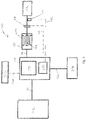
- FIG. 1 shows a generator system 100 for generating electrical power from the rotation of a vehicle axle 102.
- the generator system 100 comprises at least a generator 106, an electrically-actuated clutch 104, and a processor 108 configured to monitor an electrical output of the generator 106.
- the generator 106 is selectively connected to the axle 102 via the electrically-actuated clutch 104.
- the generator 106 comprises a rotor 106a and a stator 106b.
- the clutch 104 has an engaged position in which rotation of the axle 102 is transmitted to the rotor 106a, to turn the rotor 106a relative to the stator 106b.
- the clutch 104 also has a disengaged position in which rotation of the axle 102 is not transmitted to the rotor 106a.
- the generator 106 is electrically connected via an electrical line 118 to a control unit 126.
- the control unit 126 houses the processor 108 and a battery 110.
- the control unit 126 is electrically and communicatively connected to a refrigeration unit 112 and is configured to selectively provide electrical power to the refrigeration unit 112.
- the connection between the refrigeration unit 112 and the control unit 126 may be via one or more electrical lines 120.
- the control unit 126 may also selectively connect to a grid power supply 114 via an electrical line 124.
- the battery 110 may be charged from the grid power supply 114 when the control unit 126 is connected to the grid power supply 114.
- the battery 110 may be charged by electrical power from the generator 106, e.g. when a battery charge level is below a predetermined level.
- the battery 110 provides electrical power to the processor 108. This allows the processor 108 to function even when the generator 106 is not producing electrical power.
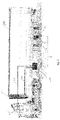
- the vehicle axle 102 may be an axle of a trailer 200.
- Trailers 200 are commonly used to transport goods and are pulled by a tractor 300 (also sometimes referred to as a truck).
- a given trailer 200 may be readily connected to and disconnected from different tractors 300.
- the tractor 300 provides the motive power to pull the trailer 200, and the trailer 200 typically has no engine or other means for turning its wheels. Instead, the trailer 200 relies entirely on tractors (e.g. tractor 300) to move the trailer 200 from place to place.
- the trailer 200 in Figure 2 is a refrigerated trailer and has the refrigeration system 112.
- the refrigeration system 112 is arranged to provide temperature control to the interior of the trailer, in order to keep goods stored therein at a predetermined temperature or within a predetermined temperature range. Operation of the refrigeration system 112 may be controlled, at least in part, by the processor 108 of the control unit 126.
- the control unit 126 is mounted to the trailer 200 and the generator 106 is mounted to or adjacent to the axle 102.
- a communication link 128 is provided to communicatively connect the control unit 126 with a computer 310 on the tractor 300.
- the computer 310 may provide information to a driver in the tractor 300, e.g. to provide information on any of: the operation and/or performance of the refrigeration system 112, the operation and/or performance of the generator 106, the charge level of the battery 110, and the position of the clutch 104 (i.e. engaged position vs disengaged position).
- the communication link may 128 be a wired link or a wireless link.
- the wheels 101 of the trailer 200 are turned by friction with the road surface.
- One pair of the wheels 101 is connected to the axle 102 to which the generator 106 is selectively connected, via the clutch 104.
- the axle 102 rotates. This rotational motion may be transmitted to the generator 106, via the clutch 104, to generate electrical power from the rotational motion.
- the trailer 200 does not have its own engine. As such, neither the axle 102 nor the generator 106 are directly driven by an engine of the tractor 300. Rather, the axle 102 is a free-wheeling axle that is turned by friction with a surface (e.g. road) over which the trailer 200 is being pulled by the tractor 300. This axle 102 is therefore distinct from a driven axle of a vehicle that is mechanically connected to an engine such that rotation of an output shaft of the engine directly results in rotation of the wheels (i.e. regardless of any contact with a road).
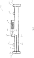
- Figure 3 shows a schematic view of an exemplary axle 102 having the generator 106 mounted thereto.
- the axle 102 has rotational end parts 150a,150b each for connecting to a wheel (e.g. wheel 101 shown in Fig 2 ) via connectors 152a,152b, respectively.
- the rotational end parts 150a,b are rotatable relative to a main axle shaft 154 that is connected to the trailer 200 via connection points 156a,156b.
- the main axle shaft 154 has a hollow interior and does not rotate relative to the trailer 200 when the trailer is in motion.
- a torque shaft 158 is connected at a first end to one of the rotational end parts 150a and extends within the hollow interior.
- the torque shaft 158 rotates along with rotation of the rotational end part 150a.
- a first gear 160a is attached to the torque shaft at or near a second end of the torque shaft 158.
- the first gear 160a connects to a second gear 160b and the second gear 160b connects to a first side of the electrically-actuated clutch 104.
- a generator shaft 162 extends from a second side of the electrically actuated clutch 104 and connects to the rotor 106a of the generator 106.
- the first and second gears 106a,b may be selected to provide a fixed gear ratio as desired.
- One or more bearings may be provided to support some or all of the torque shaft 158, generator shaft 162 and/or gears 160a,b within the main axle shaft 154.
- the generator 106 is fixed to the main axle shaft 154. However, other arrangements are envisaged, such as connecting the generator to the trailer 200 rather than to the main axle shaft 154.
- the sensor 130 may be located at any point from the wheel 101 up to the first side of the clutch 104.
- the processor 108 monitors an electrical output of the generator 106.
- the term "electrical output” encompasses any one or more of electrical voltage, electrical frequency, and electrical current. That is, the processor 108 monitors: an output voltage from the generator, an output current from the generator, and/or an output electrical frequency from the generator.
- the processor 108 also controls the electrically-actuated clutch 104 and may command the clutch 104 to actuate between the engaged and disengaged positions.
- the processor 108 is connected to the electrically-actuated clutch via a communication line 116. This actuation of the clutch 104 may be accomplished using power from the battery 110. As such, the clutch 104 may be moved between the engaged and disengaged positions even if the generator 106 is not currently producing electrical power or is producing an insufficient amount of electrical power. Alternatively, actuation of the clutch 104 may be performed using power from a grid power source 114.
- the processor 108 is configured to command the clutch 104 to move to the disengaged position if the electrical output moves outside a predetermined range. Examples of suitable predetermined ranges are disclosed below. Also discussed are specific situations that may lead to the electrical output moving outside the predetermined range.
- the predetermined range may in some cases be multiple predetermined ranges, each predetermined range for a different electrical characteristic.
- the processor 108 may monitor both electrical frequency and electrical voltage from the generator 106, and may be configured to command the clutch 104 to move to the disengaged position if either the electrical voltage moves outside the predetermined range for voltage or if the electrical frequency moves outside the predetermined range for frequency.
- a suitable predetermined range for electrical frequency may be, for example, 0 Hz to 500 Hz, and optionally 10 Hz to 500 Hz.
- a suitable predetermined range for electrical voltage may be, for example, 0 V to 600 V, and optionally may be 0 V to 450 V, and optionally 10 V to 450 V.
- a suitable predetermined range for electrical current may be, for example, from 0 A to 32 A, and optionally may be 5 A to 32A.
- the refrigeration system 112 is not required.
- the trailer 200 may be being used to transport goods that do not require a temperature controlled environment, and thus the refrigeration system 112 may be turned off.
- the processor 108 may command the clutch 104 to move to the disengaged position so that the rotor 106a is not turned within the generator 106. This may reduce wear on the generator 106 and extend its service life.
- the refrigeration system 112 may require specific characteristics of received electrical power in order to function correctly, e.g. it may require specific voltage, electrical frequency, and/or electrical current.
- the battery 110 may require specific characteristics of received power in order to recharge properly.
- the electrical output of the generator 106 may not be suitable for recharging the battery 110 and/or powering the refrigeration system 112.
- the generator 106 could produce electricity but this may have too low a frequency to meet the requirements of the refrigeration system 112 and/or battery 108.
- the processor 108 may command the clutch 104 to move to the disengaged position so that the rotor 106a is not turned within the generator 106.
- the control unit 126 may contain power conversion electronics to convert the output from the generator 106 to electrical power having different characteristics.
- the control unit may have power control electronics suitable for increasing or decreasing the voltage received from the generator, and/or for converting an A.C. output from the generator to D.C. power etc.
- the power control electronics may nonetheless require the power received from the generator 106 to have certain minimum or maximum characteristics (e.g. a minimum voltage, a maximum voltage, a minimum frequency, a maximum frequency, a minimum current, and/or a maximum current) in order to successfully produce output power that had the characteristics required by the refrigeration system 112 and/or battery 110. If the electrical output is outside this range, i.e.
- the processor 108 may command the clutch 104 to move to the disengaged position so that the rotor 106a is not turned within the generator 106. This may occur, for example, if the trailer 200 is moving too slowly such that insufficient power is generated by the generator 106.
- the battery 110 may be used to power the refrigeration system 112 instead, if required.
- the processor 108 may command the clutch 104 to move to the engaged position so that the rotor 106a turns within the generator 106 and the generator 106 generates electrical power, e.g.
- a similar situation may prevail if the trailer 200 is moving too fast, such that e.g. an electrical frequency of the power generated by the generator 106 is too high, i.e. above the predetermined range.
- the predetermined range for the electrical output of the generator 106 may be one of: a minimum and maximum voltage, a minimum and maximum frequency, and a minimum and maximum current. Specific values for these minima and maxima will depend upon the specific requirements of the refrigeration system 106, and/or battery 108, and/or power conversion electronics.
- Rotor locking may be caused, for example, by debris, failure of bearings in the generator 106, or thermal expansion/contraction of parts of the generator 106.
- the generator 106 if the generator 106 is connected to the axle 102, the generator 106 will act as a brake on the axle 102.
- This unintentional braking of the axle 102 can be a safety risk, as it could cause the trailer 200 to slip on the road, or lead to loss of control of the trailer 200 and tractor 300, which may lead to an accident.
- a sensor 130 may be arranged to sense a rotational speed and/or rotational frequency of the axle 102, e.g. as shown in Figure 1 .
- Data from the sensor 130 is communicated, via a communication link 132, to the processor 108.
- the processor 108 may convert the rotational speed or frequency of the axle 102 into an expected electrical output of the generator 106.
- the conversion of the rotational speed of the axle 102 to an expected electrical output will depend upon several factors, including: the arrangement of the generator, particularly the number of poles in the generator 106, as well as any gears (e.g. gears 160a,b) between the wheel 101 and the rotor 106a.
- the predetermined amount is to allow for measurement error in either or both of: the electrical output of the generator 106 and the rotational speed measured by the sensor 130.
- the predetermined amount may be, for example, +/- 5Hz.
- an expected voltage output or an expected current output may be calculated.
- the expected voltage output or expected current output may be compared to the electrical output of the generator 106 monitored by the processor and, if the monitored output deviates from the expected output by more than a predetermined amount, this may indicate the rotor 106a is stuck within the generator 106.
- the predetermined amount may be, for example, +/- 5V or +/- 1A, as appropriate.
- the processor 108 may determine a locked-state of the rotor 106a and command the clutch 104 to move to the disengaged position so that the generator 106 does not brake the axle 102.
- the processor 108 would calculate an expected electrical output frequency of 30 Hz. If the processor detects an electrical output frequency of 28 Hz, then it may determine that the generator 106 is operating normally, within measurement error. However, if the processor detects an electrical output frequency of 20 Hz, this may indicate that the rotor 106a is partially sticking within the generator 106 and this sticking will be providing a unintended braking force on the axle 102. In this case, the processor 108 may command the clutch 104 to move to the disengaged position so that the generator 106 does not brake the axle 102.
- the processor may determine an overspeed state. That is, the trailer 200 may be moving faster along a road than may be safely accommodated by the generator 106. In this case, the processor 108 may command the clutch 104 to move to the disengaged position so that the generator 106 is not run faster than its design parameters.
- the predetermined maximum speed may alternatively be set based on requirements of the refrigerating system 112, battery 108, and/or power conversion electronics.
- the processor may detect this low charge and command the clutch 104 to move to the engaged position so that the generator 106 provides power and this power is used to charge the battery 110. This may occur, for example, even if the generator 106 is not otherwise required at present, e.g. not required to power the refrigeration system 112.
- the processor may also be configured to control the clutch 104 to move to the disengaged position in response to determining that the battery charge level is above a predetermined level.
- Figure 4 discloses a method 400 of controlling the generator system 100.
- Method step 402 involves monitoring an electrical output of the generator 106, using the processor 108.
- Method step 404 involves disconnecting the rotor 106a from the axle 102 when the electrical output is outside a predetermined range.
Abstract
Description
- The present disclosure relates to a generator system for connection to a vehicle axle, and to a method of controlling a generator system.
- Trailers are a type of wheeled road vehicle that are pulled by another vehicle such as a tractor, as trailers do not have an engine for powering their own wheels for rotation. Trailers are common in the transportation industry, where the trailer is used to contain cargo, and a trailer may be connected to and disconnected from different tractors (also called trucks, lorry cars, or truck cars). The driver sits in the tractor and the tractor engine provides the motive power to pull the trailer to its destination.
- Some trailers contain powered components, such as lights and/or refrigeration systems. The refrigeration system may be for cooling the cargo hold of the trailer, e.g. to preserve perishable goods such as foodstuffs or medicine. In some examples, the trailer receives all necessary electrical power from the tractor. That is, when the trailer is mounted to a given tractor, an electrical connection is also provided to provide power from the tractor battery or a generator in the tractor, to the trailer.
- It is also known to provide a generator having a rotor connected to an axle of the trailer, such that, when the trailer is pulled by a tractor, the trailer wheels are driven to rotate and this rotation is passed, via the axle, to the rotor of a generator mounted on the trailer. The generator generates electrical power for use by the trailer.
- Such conventional generators have generally been considered satisfactory for their intended purpose but there is room for improvement.
- According to a first aspect, there is provided a generator system for connection to a vehicle axle. The generator system comprises: an electrically-actuated clutch having an engaged position and a disengaged position; a generator comprising: a rotor configured to be selectively connected, via the clutch, to the vehicle axle; and a stator; wherein, in the engaged position, the rotor is connected to the vehicle axle via the clutch such that torque from rotation of the vehicle axle is transmitted to the rotor, and wherein, in the disengaged position, torque from rotation of the vehicle axle is not transmitted to the rotor. A processor is provided and is configured to control the clutch to actuate between the engaged and disengaged positions; wherein the processor is configured to monitor an electrical output of the generator, wherein the processor is configured to command the clutch to move to the disengaged position if the electrical output moves outside a predetermined range.
- The electrical output may be one or more of electrical voltage, electrical current, or electrical frequency.
- The predetermined range may be an electrical frequency range of from 0 Hz to 500 Hz; and/or the predetermined range may be an electrical voltage range of from 0 volts to 600 volts; and/or the predetermined range may be an electrical current range of from 0 amps to 32 amps.
- 500 Hz output may correspond to a maximum safe operational speed for the rotor, and so disconnecting the rotor if the output exceeds 500 Hz may protect the generator. This may also protect any connected electronic components that are frequency sensitive.
- 600 V may be a maximum rated output of the generator, and so disconnecting the rotor if the output exceeds 600 V may protect the generator and/or any connected electronic components.
- 32 amps may be a maximum rated output of the generator, and so disconnecting the rotor if the output exceeds 32 amps may protect the generator and/or any connected electronic components.
- Different generators may have a different maximum frequency output and/or different voltage output, and so the aforesaid maximum values of 500 Hz and/or 600 V and/or 32 A may be reduced by configuring the processor as appropriate (e.g. the desired values for when the processor commands the clutch to disconnect may be set by software running on the processor).
- Optionally, the minimum of the predetermined range may be 10 Hz or 10 V or 1 A. In these cases, the processor may command the clutch to the disengaged position when the power output is non-zero but is insufficient for the necessary purposes. Necessary purposes may include powering a refrigeration system and/or charging a battery.
- Similarly, a different minimum voltage or frequency or current may be set e.g. by software.
- The generator system may further comprise a sensor for detecting a rotational speed or frequency of the vehicle axle; wherein the sensor is connected to the processor, and wherein the processor is configured to: convert the detected rotational speed or frequency of the axle into an expected electrical output generated by the generator; determine a locked-state of the rotor if the monitored electrical output differs from the expected electrical output by more than a predetermined amount; and to control the clutch to move to the disengaged position in response to determining a locked-state of the rotor.
- The expected electrical output may be an expected electrical frequency, or an expected electrical voltage, or an expected electrical current, as desired.
- This may help protect a vehicle against unintended braking of the wheel(s) when the rotor is jammed (locked) within the generator. The predetermined amount allows for measurement errors in one or both of the sensed rotational speed and the detected electrical output of the generator. This helps avoid disconnecting the generator unnecessarily when everything is operating normally but a measurement error indicates a small discrepancy between the expected frequency and the detected frequency.
- The processor may be further configured to: determine an overspeed state if the detected rotational speed or frequency of the axle is above a predetermined speed or frequency; and control the clutch to move to the disengaged position in response to determining an overspeed state.
- This may protect the generator from being driven too fast, beyond its design parameters. This may also avoid letting the generator output too much power which could damage electronic components that are powered using the generator.
- The generator system may further comprise a battery, wherein the battery is configured to supply electrical power to the electrically-actuated clutch and to the processor; and wherein the generator is configured to selectively provide power to the battery to charge the battery.
- The battery may provide the power to engage/disengage the clutch to allow the generator system to be self-starting, i.e. in the case where the clutch is disengaged, the generator system has its own power to engage the clutch and thereby generate power from the generator.
- The processor may be configured to detect a battery charge level and to control the clutch to move to the disengaged position in response to determining that the battery charge level is above a predetermined level.
- In the case where the battery has low charge, it may be desirable to charge the battery using the generator, even if there is no other need for the generator power (e.g. if a refrigeration system is off etc.)
- According to a second aspect, a trailer is provided, the trailer comprising: a wheel; an axle connected to the wheel; and the generator system of the first aspect. The rotor is selectively connected to the axle via the clutch; and wherein the axle is arranged to be driven in rotation by relative motion between the trailer and a surface the trailer is on.
- The generator system may be used to provide electrical power to the trailer, e.g. to power lights or power a refrigeration system of the trailer. This can reduce or eliminate the need for electrical power to be provided to the trailer by a tractor pulling the trailer.
- It is known that rotors may jam within a generator, for example due to friction between components of the generator. In known systems where the generator is permanently connected to the axle, this provides a braking force on the axle and thus on the trailer wheel(s). This can cause a safety risk from the wheels slipping against the road surface. Further, applying heavy torque from the wheels to a jammed rotor may damage the generator. Thus, being able to disconnect the generator from axle can improve safety for the trailer and improve the lifetime of the generator.
- Additionally or alternatively, if the trailer is in motion but no electrical power is currently required from the generator, then the clutch may be disengaged to prevent the rotor unnecessarily spinning in the generator, thus reducing unnecessary wear on the generator components. Thus, being able to disconnect the generator from axle can improve the lifetime of the generator for this reason too.
- The trailer may not have an engine for driving the axle. That is, the trailer may rely entirely upon a tractor to move the trailer from place to place. In this case, the generator system is connected to an axle that is freewheeling, i.e. not directly driven in rotation by a motor. Rather, the only cause of rotation of the wheel, and therefore of the generator, comes from the trailer being pulled over a road.
- The trailer may further comprise a refrigeration system, wherein the generator system is connected to the refrigeration system and is arranged to selectively provide electrical power to the refrigeration system, under command of the processor.
- The refrigeration system may therefore be powered by the generator, and this may reduce or eliminate the need for electrical power provided by the tractor. Alternatively or additionally, the refrigeration system may be powered by the battery and/or by a grid power supply.
- The trailer may further comprise a communication link connected to the processor, wherein the processor is configured to provide information via the communication link regarding at least one of: the connection state of the electrically actuated clutch and the electrical output of the generator.
- The communication link may provide information to a tractor computer or other screen. The communication link may provide information concerning one or more of: the electrical output of the generator, whether the generator is in a locked state, whether an overspeed state is occurring, whether a refrigeration system is powered on, etc.
- According to a further aspect, there is provided a method of controlling a generator system, wherein a rotor of a generator of the generator system is arranged to be selectively connected to a vehicle axle via an electrically-actuated clutch such that, when the rotor is connected to the axle via the clutch, rotation of the vehicle axle drives the rotor to rotate within the generator. The method comprises: monitoring, using a processor, an electrical output of the generator; and disconnecting the rotor from the axle when the electrical output is outside a predetermined range.
- This method may protect the generator, e.g. from excessive wear when it is not required to generate power.
- The predetermined range may be an electrical frequency range of from 0 Hz to 500 Hz; and/or the predetermined range may be an electrical voltage range of from 0 volts to 600 volts; and/or the predetermined range may be an electrical current range of from 0 amps to 32 amps. Alternatively, the minimum of each respective predetermined range may be 10 Hz or 10 V or 1 A.
- The method may comprise: monitoring, using a sensor, a rotational speed of the vehicle axle; converting, using the processor, the rotational speed of the axle into an expected electrical ouput generated by the generator; determining, by the processor, a locked-state of the rotor when the monitored electrical output differs from the expected electrical ouput by more than a predetermined amount; and using the clutch, disconnecting the rotor from the axle in response to determining a locked-state of the rotor.
- This may help protect a vehicle against unintended braking of the wheel(s) when the rotor is jammed (locked) within the generator. The predetermined amount allows for measurement errors in one or both of the sensed rotational speed and the detected electrical output of the generator. This helps avoid disconnecting the generator unnecessarily when everything is operating normally but a measurement error indicates a small discrepancy between the expected frequency and the detected frequency.
- The method may comprise disconnecting the rotor from the axle if the rotational speed of the axle is above a predetermined rotational speed.
- This may protect the generator from being driven too fast, beyond its design parameters. This may also avoid letting the generator output too much power which could damage electronic components that are powered using the generator.
- The method may comprise monitoring, using the processor, a charge level of a battery that is selectively electrically connected to the electrical output of the generator, and charging the battery using the electrical output of the generator, when the electrical output is above a predetermined threshold and when the charge level is below a predetermined threshold.
- In this manner, the battery may be (re)charged when its charge gets too low, but can avoid overcharging the battery which can reduce battery lifetime or its ability to hold charge.
- Certain embodiments of the present disclosure will now be described in greater detail by way of example only and with reference to the accompanying drawings in which:
-
Figure 1 shows a schematic drawing of system having an axle generator selectively connected for rotation to a vehicle axle; -
Figure 2 shows a trailer and tractor incorporating the axle generator; -
Figure 3 shows a vehicle axle having the axle generator mounted thereon; and -
Figure 4 shows a method of monitoring a generator system. -
Figure 1 shows agenerator system 100 for generating electrical power from the rotation of avehicle axle 102. Thegenerator system 100 comprises at least agenerator 106, an electrically-actuatedclutch 104, and aprocessor 108 configured to monitor an electrical output of thegenerator 106. - The
generator 106 is selectively connected to theaxle 102 via the electrically-actuatedclutch 104. Thegenerator 106 comprises arotor 106a and astator 106b. The clutch 104 has an engaged position in which rotation of theaxle 102 is transmitted to therotor 106a, to turn therotor 106a relative to thestator 106b. The clutch 104 also has a disengaged position in which rotation of theaxle 102 is not transmitted to therotor 106a. - The
generator 106 is electrically connected via anelectrical line 118 to acontrol unit 126. Thecontrol unit 126 houses theprocessor 108 and abattery 110. Thecontrol unit 126 is electrically and communicatively connected to arefrigeration unit 112 and is configured to selectively provide electrical power to therefrigeration unit 112. The connection between therefrigeration unit 112 and thecontrol unit 126 may be via one or moreelectrical lines 120. - The
control unit 126 may also selectively connect to agrid power supply 114 via anelectrical line 124. Thebattery 110 may be charged from thegrid power supply 114 when thecontrol unit 126 is connected to thegrid power supply 114. - The
battery 110 may be charged by electrical power from thegenerator 106, e.g. when a battery charge level is below a predetermined level. Thebattery 110 provides electrical power to theprocessor 108. This allows theprocessor 108 to function even when thegenerator 106 is not producing electrical power. - As shown in
Figure 2 , thevehicle axle 102 may be an axle of atrailer 200. -
Trailers 200 are commonly used to transport goods and are pulled by a tractor 300 (also sometimes referred to as a truck). A giventrailer 200 may be readily connected to and disconnected fromdifferent tractors 300. Thetractor 300 provides the motive power to pull thetrailer 200, and thetrailer 200 typically has no engine or other means for turning its wheels. Instead, thetrailer 200 relies entirely on tractors (e.g. tractor 300) to move thetrailer 200 from place to place. - The
trailer 200 inFigure 2 is a refrigerated trailer and has therefrigeration system 112. Therefrigeration system 112 is arranged to provide temperature control to the interior of the trailer, in order to keep goods stored therein at a predetermined temperature or within a predetermined temperature range. Operation of therefrigeration system 112 may be controlled, at least in part, by theprocessor 108 of thecontrol unit 126. - The
control unit 126 is mounted to thetrailer 200 and thegenerator 106 is mounted to or adjacent to theaxle 102. Acommunication link 128 is provided to communicatively connect thecontrol unit 126 with acomputer 310 on thetractor 300. Thecomputer 310 may provide information to a driver in thetractor 300, e.g. to provide information on any of: the operation and/or performance of therefrigeration system 112, the operation and/or performance of thegenerator 106, the charge level of thebattery 110, and the position of the clutch 104 (i.e. engaged position vs disengaged position). - The communication link may 128 be a wired link or a wireless link.
- When the
trailer 200 is in motion on a road, e.g. due to being pulled by thetractor 300, thewheels 101 of thetrailer 200 are turned by friction with the road surface. One pair of thewheels 101 is connected to theaxle 102 to which thegenerator 106 is selectively connected, via the clutch 104. Thus, when thetrailer 200 is in motion, theaxle 102 rotates. This rotational motion may be transmitted to thegenerator 106, via the clutch 104, to generate electrical power from the rotational motion. - As mentioned above, the
trailer 200 does not have its own engine. As such, neither theaxle 102 nor thegenerator 106 are directly driven by an engine of thetractor 300. Rather, theaxle 102 is a free-wheeling axle that is turned by friction with a surface (e.g. road) over which thetrailer 200 is being pulled by thetractor 300. Thisaxle 102 is therefore distinct from a driven axle of a vehicle that is mechanically connected to an engine such that rotation of an output shaft of the engine directly results in rotation of the wheels (i.e. regardless of any contact with a road). -
Figure 3 shows a schematic view of anexemplary axle 102 having thegenerator 106 mounted thereto. - The
axle 102 hasrotational end parts 150a,150b each for connecting to a wheel (e.g. wheel 101 shown inFig 2 ) viaconnectors 152a,152b, respectively. Therotational end parts 150a,b are rotatable relative to amain axle shaft 154 that is connected to thetrailer 200 viaconnection points 156a,156b. Themain axle shaft 154 has a hollow interior and does not rotate relative to thetrailer 200 when the trailer is in motion. Atorque shaft 158 is connected at a first end to one of therotational end parts 150a and extends within the hollow interior. Thetorque shaft 158 rotates along with rotation of therotational end part 150a. Afirst gear 160a is attached to the torque shaft at or near a second end of thetorque shaft 158. Thefirst gear 160a connects to a second gear 160b and the second gear 160b connects to a first side of the electrically-actuatedclutch 104. Agenerator shaft 162 extends from a second side of the electrically actuated clutch 104 and connects to therotor 106a of thegenerator 106. The first andsecond gears 106a,b may be selected to provide a fixed gear ratio as desired. - One or more bearings (not shown) may be provided to support some or all of the
torque shaft 158,generator shaft 162 and/orgears 160a,b within themain axle shaft 154. - The
generator 106 is fixed to themain axle shaft 154. However, other arrangements are envisaged, such as connecting the generator to thetrailer 200 rather than to themain axle shaft 154. - With this arrangement, when the
trailer 200 is pulled along a road by atractor 300, friction between the road and thewheel 101 causes thewheel 101 of thetrailer 200 to rotate. With reference toFigures 2 and3 , rotation of thewheel 101 causes rotation of therotational end part 150a of the axle, which in turn causes rotation of thetorque shaft 158 and thegears 160a,b. If the clutch 104 is in the engaged position, rotation of the second gear 160b causes rotation of thegenerator shaft 162, which turns therotor 106a within thegenerator 106. If the clutch 104 is in the disengaged position, thesecond gear 106b spins freely and rotation of this gear is not passed to thegenerator 106. - The
sensor 130, if present, may be located at any point from thewheel 101 up to the first side of the clutch 104. - Returning now to
Figure 1 , theprocessor 108 monitors an electrical output of thegenerator 106. The term "electrical output" encompasses any one or more of electrical voltage, electrical frequency, and electrical current. That is, theprocessor 108 monitors: an output voltage from the generator, an output current from the generator, and/or an output electrical frequency from the generator. - The
processor 108 also controls the electrically-actuatedclutch 104 and may command the clutch 104 to actuate between the engaged and disengaged positions. Theprocessor 108 is connected to the electrically-actuated clutch via acommunication line 116. This actuation of the clutch 104 may be accomplished using power from thebattery 110. As such, the clutch 104 may be moved between the engaged and disengaged positions even if thegenerator 106 is not currently producing electrical power or is producing an insufficient amount of electrical power. Alternatively, actuation of the clutch 104 may be performed using power from agrid power source 114. - The
processor 108 is configured to command the clutch 104 to move to the disengaged position if the electrical output moves outside a predetermined range. Examples of suitable predetermined ranges are disclosed below. Also discussed are specific situations that may lead to the electrical output moving outside the predetermined range. - The predetermined range may in some cases be multiple predetermined ranges, each predetermined range for a different electrical characteristic. For example, the
processor 108 may monitor both electrical frequency and electrical voltage from thegenerator 106, and may be configured to command the clutch 104 to move to the disengaged position if either the electrical voltage moves outside the predetermined range for voltage or if the electrical frequency moves outside the predetermined range for frequency. - A suitable predetermined range for electrical frequency may be, for example, 0 Hz to 500 Hz, and optionally 10 Hz to 500 Hz.
- A suitable predetermined range for electrical voltage may be, for example, 0 V to 600 V, and optionally may be 0 V to 450 V, and optionally 10 V to 450 V.
- A suitable predetermined range for electrical current may be, for example, from 0 A to 32 A, and optionally may be 5 A to 32A.
- In some situations, the
refrigeration system 112 is not required. For example, thetrailer 200 may be being used to transport goods that do not require a temperature controlled environment, and thus therefrigeration system 112 may be turned off. In this case, theprocessor 108 may command the clutch 104 to move to the disengaged position so that therotor 106a is not turned within thegenerator 106. This may reduce wear on thegenerator 106 and extend its service life. - The
refrigeration system 112 may require specific characteristics of received electrical power in order to function correctly, e.g. it may require specific voltage, electrical frequency, and/or electrical current. Similarly, thebattery 110 may require specific characteristics of received power in order to recharge properly. - In some situations, the electrical output of the
generator 106 may not be suitable for recharging thebattery 110 and/or powering therefrigeration system 112. For example, atlow trailer 200 speeds, thegenerator 106 could produce electricity but this may have too low a frequency to meet the requirements of therefrigeration system 112 and/orbattery 108. In this case, theprocessor 108 may command the clutch 104 to move to the disengaged position so that therotor 106a is not turned within thegenerator 106. - The
control unit 126 may contain power conversion electronics to convert the output from thegenerator 106 to electrical power having different characteristics. For example, the control unit may have power control electronics suitable for increasing or decreasing the voltage received from the generator, and/or for converting an A.C. output from the generator to D.C. power etc. However, the power control electronics may nonetheless require the power received from thegenerator 106 to have certain minimum or maximum characteristics (e.g. a minimum voltage, a maximum voltage, a minimum frequency, a maximum frequency, a minimum current, and/or a maximum current) in order to successfully produce output power that had the characteristics required by therefrigeration system 112 and/orbattery 110. If the electrical output is outside this range, i.e. such that the power conversion electronics cannot convert the electrical output to a suitable electrical supply for therefrigeration system 112 and/orbattery 110, then theprocessor 108 may command the clutch 104 to move to the disengaged position so that therotor 106a is not turned within thegenerator 106. This may occur, for example, if thetrailer 200 is moving too slowly such that insufficient power is generated by thegenerator 106. Thebattery 110 may be used to power therefrigeration system 112 instead, if required. Once the electrical output is within the predetermined range (e.g. if thetrailer 200 speeds up), theprocessor 108 may command the clutch 104 to move to the engaged position so that therotor 106a turns within thegenerator 106 and thegenerator 106 generates electrical power, e.g. for provision to therefrigeration system 112 and/or to recharge thebattery 110. A similar situation may prevail if thetrailer 200 is moving too fast, such that e.g. an electrical frequency of the power generated by thegenerator 106 is too high, i.e. above the predetermined range. - In this situation, the predetermined range for the electrical output of the
generator 106 may be one of: a minimum and maximum voltage, a minimum and maximum frequency, and a minimum and maximum current. Specific values for these minima and maxima will depend upon the specific requirements of therefrigeration system 106, and/orbattery 108, and/or power conversion electronics. - One known type of malfunction of a generator (e.g. generator 106) is the rotor locking within the
generator 106. Rotor locking may be caused, for example, by debris, failure of bearings in thegenerator 106, or thermal expansion/contraction of parts of thegenerator 106. In this situation, if thegenerator 106 is connected to theaxle 102, thegenerator 106 will act as a brake on theaxle 102. This unintentional braking of theaxle 102 can be a safety risk, as it could cause thetrailer 200 to slip on the road, or lead to loss of control of thetrailer 200 andtractor 300, which may lead to an accident. - A
sensor 130 may be arranged to sense a rotational speed and/or rotational frequency of theaxle 102, e.g. as shown inFigure 1 . Data from thesensor 130 is communicated, via acommunication link 132, to theprocessor 108. Theprocessor 108 may convert the rotational speed or frequency of theaxle 102 into an expected electrical output of thegenerator 106. The conversion of the rotational speed of theaxle 102 to an expected electrical output will depend upon several factors, including: the arrangement of the generator, particularly the number of poles in thegenerator 106, as well as any gears (e.g. gears 160a,b) between thewheel 101 and therotor 106a. - If the electrical frequency output by the
generator 106 deviates from the expected electrical output by more than a predetermined amount, this may indicate that therotor 106a is stuck within thegenerator 106. The predetermined amount is to allow for measurement error in either or both of: the electrical output of thegenerator 106 and the rotational speed measured by thesensor 130. The predetermined amount may be, for example, +/- 5Hz. - In a similar manner, an expected voltage output or an expected current output may be calculated. The expected voltage output or expected current output may be compared to the electrical output of the
generator 106 monitored by the processor and, if the monitored output deviates from the expected output by more than a predetermined amount, this may indicate therotor 106a is stuck within thegenerator 106. The predetermined amount may be, for example, +/- 5V or +/- 1A, as appropriate. - In this scenario, the
processor 108 may determine a locked-state of therotor 106a and command the clutch 104 to move to the disengaged position so that thegenerator 106 does not brake theaxle 102. - By way of example only, if the
sensor 130 detects theaxle 102 is rotating at 10 Hz (600 rpm - which might typically correspond to a vehicle speed of 60 km per hour), and the generator is a three pole generator then theprocessor 108 would calculate an expected electrical output frequency of 30 Hz. If the processor detects an electrical output frequency of 28 Hz, then it may determine that thegenerator 106 is operating normally, within measurement error. However, if the processor detects an electrical output frequency of 20 Hz, this may indicate that therotor 106a is partially sticking within thegenerator 106 and this sticking will be providing a unintended braking force on theaxle 102. In this case, theprocessor 108 may command the clutch 104 to move to the disengaged position so that thegenerator 106 does not brake theaxle 102. - If the rotational speed measured by the
sensor 130 exceeds a predetermined maximum speed, the processor may determine an overspeed state. That is, thetrailer 200 may be moving faster along a road than may be safely accommodated by thegenerator 106. In this case, theprocessor 108 may command the clutch 104 to move to the disengaged position so that thegenerator 106 is not run faster than its design parameters. The predetermined maximum speed may alternatively be set based on requirements of therefrigerating system 112,battery 108, and/or power conversion electronics. - In a situation where the
battery 110 charge is low, the processor may detect this low charge and command the clutch 104 to move to the engaged position so that thegenerator 106 provides power and this power is used to charge thebattery 110. This may occur, for example, even if thegenerator 106 is not otherwise required at present, e.g. not required to power therefrigeration system 112. - In this situation, the processor may also be configured to control the clutch 104 to move to the disengaged position in response to determining that the battery charge level is above a predetermined level.
-
Figure 4 discloses amethod 400 of controlling thegenerator system 100.Method step 402 involves monitoring an electrical output of thegenerator 106, using theprocessor 108.Method step 404 involves disconnecting therotor 106a from theaxle 102 when the electrical output is outside a predetermined range. -
- 100
- generator system
- 102
- axle
- 104
- (electrically-actuated) clutch
- 106
- generator
- 106a
- rotor (of generator)
- 106b
- stator (of generator)
- 108
- processor
- 110
- battery
- 112
- refrigeration system
- 114
- grid power supply
- 116
- communication line (from processor to clutch)
- 118
- electrical line (connecting generator to control unit)
- 120
- electrical line(s) (connecting control unit to refrigeration system)
- 124
- electrical line (from grid power supply to control unit)
- 126
- control unit
- 128
- communication link (to tractor)
- 130
- sensor
- 132
- communication link (from sensor to processor)
- 150a,b
- rotational end parts of axle
- 152a,b
- connectors
- 154
- main axle shaft
- 156a,b
- connection points
- 158
- torque shaft
- 160a,b
- first and second gears
- 162
- generator shaft
- 200
- trailer
- 300
- tractor
- 310
- computer (of tractor)
- 400-404
- method steps
Claims (15)
- A generator system (100) for connection to a vehicle axle (102); the generator system comprising:an electrically-actuated clutch (104) having an engaged position and a disengaged position;a generator (106) comprising:a rotor (106a) configured to be selectively connected, via the clutch, to the vehicle axle; anda stator (106b);wherein, in the engaged position, the rotor is connected to the vehicle axle via the clutch such that torque from rotation of the vehicle axle is transmitted to the rotor, andwherein, in the disengaged position, torque from rotation of the vehicle axle is not transmitted to the rotor; anda processor (108) configured to control the clutch to actuate between the engaged and disengaged positions;wherein the processor is configured to monitor an electrical output of the generator, wherein the processor is configured to command the clutch to move to the disengaged position if the electrical output moves outside a predetermined range.
- The generator system of claim 1 or 2, wherein the predetermined range is an electrical frequency range of from 0 Hz to 500 Hz; and/or wherein the predetermined range is an electrical voltage range of from 0 volts to 600 volts; and/or wherein the predetermined range is an electrical current range of from 0 amps to 32 amps.
- The generator system of any preceding claim, further comprising a sensor (130) for detecting a rotational speed or frequency of the vehicle axle; wherein the sensor is connected to the processor (108), and wherein the processor is configured to:convert the detected rotational speed or frequency of the axle into an expected electrical output generated by the generator;determine a locked-state of the rotor if the monitored electrical output differs from the expected electrical output by more than a predetermined amount; and tocontrol the clutch (104) to move to the disengaged position in response to determining a locked-state of the rotor.
- The generator system of claim 3, wherein the processor (108) is further configured to:determine an overspeed state if the detected rotational speed or frequency of the axle is above a predetermined speed or frequency; andcontrol the clutch to move to the disengaged position in response to determining an overspeed state.
- The generator system of any preceding claim, further comprising a battery (110), wherein the battery is configured to supply electrical power to the electrically-actuated clutch (104) and to the processor (108); and wherein the generator (106) is configured to selectively provide power to the battery (110) to charge the battery.
- The generator system of claim 5, wherein the processor (108) is configured to detect a battery charge level and to control the clutch (104) to move to the disengaged position in response to determining that the battery charge level is above a predetermined level.
- A trailer (200) comprising:a wheel (101);an axle (102) connected to the wheel (101); andthe generator system of any preceding claim;wherein the rotor (106a) is selectively connected to the axle (102) via the clutch (104); andwherein the axle (102) is arranged to be driven in rotation by relative motion between the trailer and a surface the trailer is on.
- The trailer of claim 7, wherein the trailer (200) does not have an engine arranged to drive the axle (102).
- The trailer of claim 7 or 8, further comprising a refrigeration system (112), wherein the generator system is connected to the refrigeration system and is arranged to selectively provide electrical power to the refrigeration system, under command of the processor (108).
- The trailer of claim 7, 8, or 9, further comprising a communication link (128) connected to the processor, wherein the processor is configured to provide information via the communication link regarding at least one of: the connection state of the electrically actuated clutch and the electrical output of the generator.
- A method (400) of controlling a generator system (100), wherein a rotor (106a) of a generator (106) of the generator system is arranged to be selectively connected to a vehicle axle (102) via an electrically-actuated clutch (104) such that, when the rotor is connected to the axle via the clutch, rotation of the vehicle axle drives the rotor to rotate within the generator, the method comprising:monitoring (402), using a processor (108), an electrical output of the generator; anddisconnecting (404) the rotor from the axle when the electrical output is outside a predetermined range.
- The method according to claim 11, the predetermined range is an electrical frequency range of from 0Hz to 500Hz; and/or wherein the predetermined range is an electrical voltage range of from 0 volts to 600 volts; and/or wherein the predetermined range is an electrical current range of from 0 amps to 32 amps.
- The method according to claim 11 or 12, comprisingmonitoring, using a sensor (130), a rotational speed of the vehicle axle;converting, using the processor (108), the rotational speed of the axle into an expected electrical output generated by the generator;determining, by the processor (108), a locked-state of the rotor when the monitored electrical output differs from the expected electrical output by more than a predetermined amount; andusing the clutch (104), disconnecting the rotor (106a) from the axle (102) in response to determining a locked-state of the rotor.
- The method according to claim 13, comprising
disconnecting the rotor from the axle if the rotational speed of the axle is above a predetermined rotational speed. - The method according to any of claims 11 to 14, comprisingmonitoring, using the processor (108), a charge level of a battery (108) that is selectively electrically connected to the electrical output of the generator (106), andcharging the battery using the electrical output of the generator, when the electrical output is above a predetermined threshold and when the charge level is below a predetermined threshold.
Priority Applications (3)
| Application Number | Priority Date | Filing Date | Title |
|---|---|---|---|
| EP21167687.9A EP4072003A1 (en) | 2021-04-09 | 2021-04-09 | Axle generator |
| CN202210365924.6A CN115195474A (en) | 2021-04-09 | 2022-04-08 | Axle generator |
| US17/716,044 US20220329183A1 (en) | 2021-04-09 | 2022-04-08 | Axle generator |
Applications Claiming Priority (1)
| Application Number | Priority Date | Filing Date | Title |
|---|---|---|---|
| EP21167687.9A EP4072003A1 (en) | 2021-04-09 | 2021-04-09 | Axle generator |
Publications (1)
| Publication Number | Publication Date |
|---|---|
| EP4072003A1 true EP4072003A1 (en) | 2022-10-12 |
Family
ID=75441825
Family Applications (1)
| Application Number | Title | Priority Date | Filing Date |
|---|---|---|---|
| EP21167687.9A Pending EP4072003A1 (en) | 2021-04-09 | 2021-04-09 | Axle generator |
Country Status (3)
| Country | Link |
|---|---|
| US (1) | US20220329183A1 (en) |
| EP (1) | EP4072003A1 (en) |
| CN (1) | CN115195474A (en) |
Citations (3)
| Publication number | Priority date | Publication date | Assignee | Title |
|---|---|---|---|---|
| US20070187957A1 (en) * | 2006-02-10 | 2007-08-16 | Roger Harrison | Power Generating Unit on Semi-Trailer for Energy Recovery and Storage |
| JP2009214587A (en) * | 2008-03-07 | 2009-09-24 | Nissan Motor Co Ltd | Vehicular driving controller, and control method for vehicular driving controller |
| WO2012045056A2 (en) * | 2010-10-01 | 2012-04-05 | Arnold Brian R | Refrigeration system |
Family Cites Families (6)
| Publication number | Priority date | Publication date | Assignee | Title |
|---|---|---|---|---|
| US5265435A (en) * | 1992-12-31 | 1993-11-30 | Phyllis M. Morefield | Vehicle refrigeration system |
| US20080174174A1 (en) * | 2007-01-22 | 2008-07-24 | James S. Burns | Passive Truck Trailer Braking Regeneration and Propulsion System and Method |
| US8723344B1 (en) * | 2010-06-24 | 2014-05-13 | James Dierickx | Energy harvesting system |
| NL2015587B1 (en) * | 2015-09-28 | 2017-04-21 | Trs Transp B V | A vehicle comprising a wheel driven generator for charging a battery. |
| EP4071981B1 (en) * | 2021-04-06 | 2023-05-31 | Carrier Fire & Security EMEA BV | Power management system for a transport refrigeration unit |
| EP4147898A1 (en) * | 2021-09-10 | 2023-03-15 | Carrier Corporation | Transport power generator system |
-
2021
- 2021-04-09 EP EP21167687.9A patent/EP4072003A1/en active Pending
-
2022
- 2022-04-08 US US17/716,044 patent/US20220329183A1/en active Pending
- 2022-04-08 CN CN202210365924.6A patent/CN115195474A/en active Pending
Patent Citations (3)
| Publication number | Priority date | Publication date | Assignee | Title |
|---|---|---|---|---|
| US20070187957A1 (en) * | 2006-02-10 | 2007-08-16 | Roger Harrison | Power Generating Unit on Semi-Trailer for Energy Recovery and Storage |
| JP2009214587A (en) * | 2008-03-07 | 2009-09-24 | Nissan Motor Co Ltd | Vehicular driving controller, and control method for vehicular driving controller |
| WO2012045056A2 (en) * | 2010-10-01 | 2012-04-05 | Arnold Brian R | Refrigeration system |
Also Published As
| Publication number | Publication date |
|---|---|
| CN115195474A (en) | 2022-10-18 |
| US20220329183A1 (en) | 2022-10-13 |
Similar Documents
| Publication | Publication Date | Title |
|---|---|---|
| JP4889279B2 (en) | AC drive system for electric vehicles | |
| US7071642B2 (en) | Method and apparatus for adaptive control of traction drive units in a hybrid vehicle | |
| JP3698411B2 (en) | VEHICLE POWER GENERATION DEVICE AND ITS CONTROL METHOD | |
| US6722456B2 (en) | Hybrid vehicle | |
| US6232729B1 (en) | Motor control device for an electric vehicle capable of preventing a battery of the vehicle from being overcharged | |
| US11897521B2 (en) | Vehicle electric supply system | |
| CA2525269C (en) | Ac drive system for electrically operated vehicle | |
| WO2009139305A1 (en) | Vehicle control device | |
| US7650216B2 (en) | Vehicle driving system with adaptive skid control | |
| KR20060132980A (en) | System and method for starting a combustion engine of a hybrid vehicle | |
| US9180765B2 (en) | Hybrid powertrain with centrifugally-actuated motor disconnect clutch and method of control | |
| CN112248825B (en) | Pre-torque control system and control method for electric transmission mining dump truck | |
| CN112498302A (en) | Electric drive module with independent drive units having friction brakes selectively engaged with each other | |
| EP4072003A1 (en) | Axle generator | |
| US20200254900A1 (en) | Vehicle electric supply system | |
| JPH11262101A (en) | Permanent magnet wheel-in motor | |
| US11548360B2 (en) | Electric axle assembly | |
| CN110831799A (en) | Method for starting a hybrid vehicle with increased battery power | |
| KR20210121364A (en) | System and method for preventing acceleration of electric vehicle | |
| WO2024062747A1 (en) | Malfunction determination device for transaxle oil temperature sensor | |
| WO2024080898A1 (en) | Method and system for controlling a traction speed of a mining vehicle during downhill driving | |
| CN117465185A (en) | Power system for transport refrigeration unit | |
| JP2003220841A (en) | Four-wheel drive controller | |
| SE1150685A1 (en) | Parallel hybrid system and method of a parallel hybrid system | |
| JPH08294201A (en) | Neutral device for electric car |
Legal Events
| Date | Code | Title | Description |
|---|---|---|---|
| PUAI | Public reference made under article 153(3) epc to a published international application that has entered the european phase |
Free format text: ORIGINAL CODE: 0009012 |
|
| STAA | Information on the status of an ep patent application or granted ep patent |
Free format text: STATUS: THE APPLICATION HAS BEEN PUBLISHED |
|
| AK | Designated contracting states |
Kind code of ref document: A1 Designated state(s): AL AT BE BG CH CY CZ DE DK EE ES FI FR GB GR HR HU IE IS IT LI LT LU LV MC MK MT NL NO PL PT RO RS SE SI SK SM TR |
|
| STAA | Information on the status of an ep patent application or granted ep patent |
Free format text: STATUS: REQUEST FOR EXAMINATION WAS MADE |
|
| 17P | Request for examination filed |
Effective date: 20221128 |
|
| RBV | Designated contracting states (corrected) |
Designated state(s): AL AT BE BG CH CY CZ DE DK EE ES FI FR GB GR HR HU IE IS IT LI LT LU LV MC MK MT NL NO PL PT RO RS SE SI SK SM TR |