EP4071588A1 - System for detecting a touch gesture of a user, device comprising the system, and method - Google Patents
System for detecting a touch gesture of a user, device comprising the system, and method Download PDFInfo
- Publication number
- EP4071588A1 EP4071588A1 EP22167231.4A EP22167231A EP4071588A1 EP 4071588 A1 EP4071588 A1 EP 4071588A1 EP 22167231 A EP22167231 A EP 22167231A EP 4071588 A1 EP4071588 A1 EP 4071588A1
- Authority
- EP
- European Patent Office
- Prior art keywords
- signal
- acc
- detecting
- peak
- filt
- Prior art date
- Legal status (The legal status is an assumption and is not a legal conclusion. Google has not performed a legal analysis and makes no representation as to the accuracy of the status listed.)
- Granted
Links
Images



Classifications
-
- G—PHYSICS
- G06—COMPUTING OR CALCULATING; COUNTING
- G06F—ELECTRIC DIGITAL DATA PROCESSING
- G06F3/00—Input arrangements for transferring data to be processed into a form capable of being handled by the computer; Output arrangements for transferring data from processing unit to output unit, e.g. interface arrangements
- G06F3/01—Input arrangements or combined input and output arrangements for interaction between user and computer
- G06F3/03—Arrangements for converting the position or the displacement of a member into a coded form
- G06F3/033—Pointing devices displaced or positioned by the user, e.g. mice, trackballs, pens or joysticks; Accessories therefor
- G06F3/0346—Pointing devices displaced or positioned by the user, e.g. mice, trackballs, pens or joysticks; Accessories therefor with detection of the device orientation or free movement in a three-dimensional [3D] space, e.g. 3D mice, 6-DOF [six degrees of freedom] pointers using gyroscopes, accelerometers or tilt-sensors
-
- G—PHYSICS
- G06—COMPUTING OR CALCULATING; COUNTING
- G06F—ELECTRIC DIGITAL DATA PROCESSING
- G06F3/00—Input arrangements for transferring data to be processed into a form capable of being handled by the computer; Output arrangements for transferring data from processing unit to output unit, e.g. interface arrangements
- G06F3/01—Input arrangements or combined input and output arrangements for interaction between user and computer
- G06F3/03—Arrangements for converting the position or the displacement of a member into a coded form
- G06F3/041—Digitisers, e.g. for touch screens or touch pads, characterised by the transducing means
- G06F3/0416—Control or interface arrangements specially adapted for digitisers
- G06F3/0418—Control or interface arrangements specially adapted for digitisers for error correction or compensation, e.g. based on parallax, calibration or alignment
-
- G—PHYSICS
- G06—COMPUTING OR CALCULATING; COUNTING
- G06F—ELECTRIC DIGITAL DATA PROCESSING
- G06F1/00—Details not covered by groups G06F3/00 - G06F13/00 and G06F21/00
- G06F1/16—Constructional details or arrangements
- G06F1/1613—Constructional details or arrangements for portable computers
- G06F1/1633—Constructional details or arrangements of portable computers not specific to the type of enclosures covered by groups G06F1/1615 - G06F1/1626
- G06F1/1684—Constructional details or arrangements related to integrated I/O peripherals not covered by groups G06F1/1635 - G06F1/1675
-
- G—PHYSICS
- G06—COMPUTING OR CALCULATING; COUNTING
- G06F—ELECTRIC DIGITAL DATA PROCESSING
- G06F1/00—Details not covered by groups G06F3/00 - G06F13/00 and G06F21/00
- G06F1/16—Constructional details or arrangements
- G06F1/1613—Constructional details or arrangements for portable computers
- G06F1/1633—Constructional details or arrangements of portable computers not specific to the type of enclosures covered by groups G06F1/1615 - G06F1/1626
- G06F1/1684—Constructional details or arrangements related to integrated I/O peripherals not covered by groups G06F1/1635 - G06F1/1675
- G06F1/1694—Constructional details or arrangements related to integrated I/O peripherals not covered by groups G06F1/1635 - G06F1/1675 the I/O peripheral being a single or a set of motion sensors for pointer control or gesture input obtained by sensing movements of the portable computer
-
- G—PHYSICS
- G06—COMPUTING OR CALCULATING; COUNTING
- G06F—ELECTRIC DIGITAL DATA PROCESSING
- G06F3/00—Input arrangements for transferring data to be processed into a form capable of being handled by the computer; Output arrangements for transferring data from processing unit to output unit, e.g. interface arrangements
- G06F3/01—Input arrangements or combined input and output arrangements for interaction between user and computer
- G06F3/017—Gesture based interaction, e.g. based on a set of recognized hand gestures
-
- G—PHYSICS
- G06—COMPUTING OR CALCULATING; COUNTING
- G06F—ELECTRIC DIGITAL DATA PROCESSING
- G06F3/00—Input arrangements for transferring data to be processed into a form capable of being handled by the computer; Output arrangements for transferring data from processing unit to output unit, e.g. interface arrangements
- G06F3/01—Input arrangements or combined input and output arrangements for interaction between user and computer
- G06F3/03—Arrangements for converting the position or the displacement of a member into a coded form
- G06F3/041—Digitisers, e.g. for touch screens or touch pads, characterised by the transducing means
- G06F3/0416—Control or interface arrangements specially adapted for digitisers
- G06F3/04166—Details of scanning methods, e.g. sampling time, grouping of sub areas or time sharing with display driving
-
- G—PHYSICS
- G06—COMPUTING OR CALCULATING; COUNTING
- G06F—ELECTRIC DIGITAL DATA PROCESSING
- G06F3/00—Input arrangements for transferring data to be processed into a form capable of being handled by the computer; Output arrangements for transferring data from processing unit to output unit, e.g. interface arrangements
- G06F3/01—Input arrangements or combined input and output arrangements for interaction between user and computer
- G06F3/03—Arrangements for converting the position or the displacement of a member into a coded form
- G06F3/041—Digitisers, e.g. for touch screens or touch pads, characterised by the transducing means
- G06F3/043—Digitisers, e.g. for touch screens or touch pads, characterised by the transducing means using propagating acoustic waves
-
- G—PHYSICS
- G06—COMPUTING OR CALCULATING; COUNTING
- G06F—ELECTRIC DIGITAL DATA PROCESSING
- G06F3/00—Input arrangements for transferring data to be processed into a form capable of being handled by the computer; Output arrangements for transferring data from processing unit to output unit, e.g. interface arrangements
- G06F3/01—Input arrangements or combined input and output arrangements for interaction between user and computer
- G06F3/048—Interaction techniques based on graphical user interfaces [GUI]
- G06F3/0487—Interaction techniques based on graphical user interfaces [GUI] using specific features provided by the input device, e.g. functions controlled by the rotation of a mouse with dual sensing arrangements, or of the nature of the input device, e.g. tap gestures based on pressure sensed by a digitiser
- G06F3/0488—Interaction techniques based on graphical user interfaces [GUI] using specific features provided by the input device, e.g. functions controlled by the rotation of a mouse with dual sensing arrangements, or of the nature of the input device, e.g. tap gestures based on pressure sensed by a digitiser using a touch-screen or digitiser, e.g. input of commands through traced gestures
-
- G—PHYSICS
- G06—COMPUTING OR CALCULATING; COUNTING
- G06F—ELECTRIC DIGITAL DATA PROCESSING
- G06F3/00—Input arrangements for transferring data to be processed into a form capable of being handled by the computer; Output arrangements for transferring data from processing unit to output unit, e.g. interface arrangements
- G06F3/01—Input arrangements or combined input and output arrangements for interaction between user and computer
- G06F3/048—Interaction techniques based on graphical user interfaces [GUI]
- G06F3/0487—Interaction techniques based on graphical user interfaces [GUI] using specific features provided by the input device, e.g. functions controlled by the rotation of a mouse with dual sensing arrangements, or of the nature of the input device, e.g. tap gestures based on pressure sensed by a digitiser
- G06F3/0488—Interaction techniques based on graphical user interfaces [GUI] using specific features provided by the input device, e.g. functions controlled by the rotation of a mouse with dual sensing arrangements, or of the nature of the input device, e.g. tap gestures based on pressure sensed by a digitiser using a touch-screen or digitiser, e.g. input of commands through traced gestures
- G06F3/04883—Interaction techniques based on graphical user interfaces [GUI] using specific features provided by the input device, e.g. functions controlled by the rotation of a mouse with dual sensing arrangements, or of the nature of the input device, e.g. tap gestures based on pressure sensed by a digitiser using a touch-screen or digitiser, e.g. input of commands through traced gestures for inputting data by handwriting, e.g. gesture or text
-
- H—ELECTRICITY
- H03—ELECTRONIC CIRCUITRY
- H03K—PULSE TECHNIQUE
- H03K17/00—Electronic switching or gating, i.e. not by contact-making and –breaking
- H03K17/94—Electronic switching or gating, i.e. not by contact-making and –breaking characterised by the way in which the control signals are generated
- H03K17/96—Touch switches
-
- G—PHYSICS
- G06—COMPUTING OR CALCULATING; COUNTING
- G06F—ELECTRIC DIGITAL DATA PROCESSING
- G06F2200/00—Indexing scheme relating to G06F1/04 - G06F1/32
- G06F2200/16—Indexing scheme relating to G06F1/16 - G06F1/18
- G06F2200/163—Indexing scheme relating to constructional details of the computer
- G06F2200/1636—Sensing arrangement for detection of a tap gesture on the housing
-
- G—PHYSICS
- G06—COMPUTING OR CALCULATING; COUNTING
- G06F—ELECTRIC DIGITAL DATA PROCESSING
- G06F2203/00—Indexing scheme relating to G06F3/00 - G06F3/048
- G06F2203/041—Indexing scheme relating to G06F3/041 - G06F3/045
- G06F2203/04106—Multi-sensing digitiser, i.e. digitiser using at least two different sensing technologies simultaneously or alternatively, e.g. for detecting pen and finger, for saving power or for improving position detection
-
- G—PHYSICS
- G06—COMPUTING OR CALCULATING; COUNTING
- G06F—ELECTRIC DIGITAL DATA PROCESSING
- G06F3/00—Input arrangements for transferring data to be processed into a form capable of being handled by the computer; Output arrangements for transferring data from processing unit to output unit, e.g. interface arrangements
- G06F3/01—Input arrangements or combined input and output arrangements for interaction between user and computer
- G06F3/03—Arrangements for converting the position or the displacement of a member into a coded form
- G06F3/041—Digitisers, e.g. for touch screens or touch pads, characterised by the transducing means
- G06F3/044—Digitisers, e.g. for touch screens or touch pads, characterised by the transducing means by capacitive means
Definitions
- the present invention relates to a system for detecting a touch gesture of a user, a device comprising the detection system, and a method for detecting a touch gesture of a user.
- buttons which are subject to breakage due to structural weakness, use of fragile flexible PCBs, problems of water resistance, etc.
- buttons based on capacitive sensors particularly suitable for implementation on full-screen devices; however they are not always reliable as they are subject to disturbances resulting from the presence of environmental electrical charge.
- MEMS accelerometers are used to implement electronic buttons, as they are suitable for detecting movements resulted from the touch, or "tap", (or double tap) of the user, exploiting suitable algorithms that detect and process the acceleration data provided by these MEMS accelerometers. Even this solution, however, is subject to environmental or use conditions that may cause a false touch detection (for example due to accelerations resulting from movements of the user's body which are similar to a touch even if they are not such).
- the touch gesture is identified by processing and monitoring an acceleration signal or vibratory signal, provided by an accelerometer following a touch gesture, filtered through a high-pass filter.
- the high-pass filter is, in particular, configured to filter the low frequency signal components (e.g., acceleration due to gravity, movements attributable to human activity) and leave the high frequency signal components, including the signal components attributable to touch, unaltered.
- the high frequency components of interest for the present invention are higher than 50 Hz.
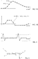
- the filtering is, in particular, obtained through a digital "Slope" filter. Therefore, with reference to Figures 1A and 1B , the raw signal provided by the accelerometer (in Figure 1A , the signal S acc_raw ) is sampled (i.e., converted into digital); again in Figure 1A , the n-th sample at time t n is identified as acc(t n ) and the sample immediately preceding time t n-1 is identified as acc(t n-1 ).
- Figure 1B illustrates the signal of Figure 1A filtered through the Slope filter (filtered signal S acc_filt ).
- the threshold may be of a fixed type (preset and/or configurable) or of adaptive type.
- Figure 2 shows, by way of example, a further accelerometric signal, filtered with the Slope filter according to what has been described with reference to Figure 1B.
- Figure 2 also shows two thresholds (one positive +Th and one negative -Th).
- the exceedance of the threshold +Th occurs by two samples acc_filt(ti) and acc_filt(t 11 ) in two respective time instants t 1 and t 11 and causes the generation of an interrupt event that identifies the occurred touch at the times t 2 and t 12 since the signal returns within the range defined by the thresholds -Th and +Th by a predefined time.
- This technical solution has the advantage of requiring low energy consumption and low cost; furthermore, it allows to obtain high accuracy in the identification of any touch event, but at the same time generates a significant number of false positives, for example in cases wherein the accelerometer detects vibrations resulting from an unwanted touch in proximity to the device (for example on the strap of a smartwatch, and in other similar situations).
- touch sensor technology is not applicable to any device (for example to earphones) due to the size and/or current consumption required for implementing a touch sensor.
- Patent document US2010/060604 discloses an advanced technique of user interaction with compact, portable, handheld devices, larger electronic devices and other surfaces and objects.
- the particular component arrays, configuration modes and analytic methodologies disclosed are directed toward logical interpretation of device motions resulting from vector impulses as user data inputs and commands.
- Patent document US2010/256947 relates in general to a system and method in which a directional tap detection algorithm and a tri-axis accelerometer extend the number of unique buttonless inputs available for small mobile devices like cell phones and MP3 players.
- the algorithm analyzes acceleration data from the single accelerometer to detect the direction (X+, X-, Y+, Y-, Z+, Z-) and number (single or double) of taps, yielding 12 unique inputs.
- Patent document WO2010/045498 relates generally to motion sensing devices, and more specifically to recognizing motion gestures based on motion sensors of a motion sensing device.
- Patent document EP3402074 concerns a processor for processing the output of a proximity sensor, and a smart proximity sensor that is combined with a processor that is arranged to output a signal that discriminates between the proximity to a human body and the proximity to an inanimate object.
- Patent document WO2020/201341 relates to on-head detection of hearing devices, such as headsets or headphones.
- Patent document US2021/232227 published after the filing date of the present application, relates to a system for detection of a touch gesture of a user on a detection surface.
- a system for detecting a touch gesture of a user a device comprising the detection system, and a method for detecting a touch gesture of a user are provided, as defined in the attached claims.
- the system for detecting a touch gesture of a user on a detection surface comprises:
- the operation of detecting said signal characteristic comprises: calculating a filtered vibration signal by filtering, through a high-pass filter, the vibration signal; detecting a first peak of the filtered vibration signal exceeding a first threshold; and detecting a second peak of the filtered vibration signal exceeding a second threshold, wherein the first threshold is one of a positive threshold and a negative threshold, and the second threshold is the other of said positive threshold and said negative threshold.
- the processing unit is further configured to sample the vibration signal, and the operation of calculating the filtered vibration signal is carried out using a digital filter, said operation of detecting the first peak comprising: detecting a first sample of the filtered vibration signal which exceeds the first threshold; detecting a second sample of the filtered vibration signal immediately preceding the first sample and having a value, in modulus, which is lower than the value, in modulus, of the first sample; and detecting a third sample of the filtered vibration signal immediately following the first sample and having a value, in modulus, which is lower than the value, in modulus, of the first sample, said first peak corresponding to the first sample.
- said operation of detecting the second peak comprises: detecting a fourth sample of the filtered vibration signal which exceeds the second threshold; detecting a fifth sample of the filtered vibration signal immediately preceding the fourth sample and having a value, in modulus, which is lower than the value, in modulus, of the fourth sample; and detecting a sixth sample of the filtered vibration signal immediately following the fourth sample and having a value, in modulus, which is lower than the value, in modulus, of the fourth sample, said second peak corresponding to the fourth sample.
- the operation of detecting said signal characteristic further comprises verifying that the first peak and the second peak are at a mutual distance, in terms of number of samples comprised between the first peak and the second peak, which is lower than a maximum value of number of samples.
- the operation of detecting, in the vibration signal, a stationarity condition preceding said signal characteristic comprises: after detecting the first peak, verifying that the values of a first plurality of samples of the filtered vibration signal preceding the first peak are comprised in a first range of reference values.
- the operation of detecting, in the vibration signal, a stationarity condition following said signal characteristic comprises: after detecting the second peak, verifying that the values of a second plurality of samples of the filtered vibration signal following the second peak are comprised in a second range of reference values.
- the operation of detecting, in the vibration signal, a stationarity condition following said signal characteristic further comprises discarding a third plurality of samples of the filtered vibration signal immediately following the second peak and comprised between the second peak and said second plurality of samples of the filtered vibration signal.
- system further comprises an electrostatic charge variation sensor, operatively coupled to the processing unit, configured to detect an electrostatic charge variation at said detection surface and, as a result, generate a charge variation signal.
- an electrostatic charge variation sensor operatively coupled to the processing unit, configured to detect an electrostatic charge variation at said detection surface and, as a result, generate a charge variation signal.
- the processing unit is further configured to generate a variance signal by calculating the variance of the charge variation signal.
- the processing unit is further configured to detect a maximum point of the variance signal when said signal characteristic which can be correlated to said touch gesture of the user is detected in the vibration signal.
- the processing unit is further configured to: verify whether the maximum point of the variance signal is in a predefined relationship with a third threshold, and in the event that both the signal characteristic and the stationarity condition preceding and/or following said signal characteristic have been detected, validate said touch gesture only if the maximum point of the variance signal meets said predefined relationship with the third threshold.
- the processing unit is further configured to: in the event that both the signal characteristic and the stationarity condition preceding and/or following said signal characteristic have been detected, and if the maximum point of the variance signal meets said predefined relationship with the third threshold, verify whether the variance signal is in a stationarity condition and validate said touch gesture only if the variance signal meets said stationarity condition.
- the stationarity condition of the variance signal is met if at least one current sample of the variance signal has a value comprised within a range of stationarity reference values.
- one embodiment provides the step of detecting a touch event that persists over time if the variance signal remains above a fourth threshold for a time which is longer than a predefined touch time.
- the present invention also relates to a method for detecting a touch gesture of a user on a detection surface, using a system which comprises: a processing unit; and an accelerometer, operatively coupled to the processing unit, configured to detect a vibration at said detection surface and generate a corresponding vibration signal, the method comprising the steps, carried out by the processing unit, of: acquiring the vibration signal, detecting, in the vibration signal, a signal characteristic which can be correlated to said touch gesture of the user, detecting, in the vibration signal, a stationarity condition preceding and/or following said detected signal characteristic, and validating said touch gesture by the user in the event that both the signal characteristic and the stationarity condition preceding and/or following said signal characteristic have been detected.
- the step of detecting said signal characteristic comprises: calculating a filtered vibration signal by filtering, through a high-pass filter, the vibration signal; detecting a first peak of the filtered vibration signal exceeding a first threshold; and detecting a second peak of the filtered vibration signal exceeding a second threshold, wherein the first threshold is one of a positive threshold and a negative threshold, and the second threshold is the other of said positive threshold and said negative threshold.
- the method comprises the step of sampling the vibration signal, and wherein the step of calculating the filtered vibration signal is carried out using a digital filter, said step of detecting the first peak comprising: detecting a first sample of the filtered vibration signal that exceeds the first threshold; detecting a second sample of the filtered vibration signal immediately preceding the first sample and having a value, in modulus, which is lower than the value, in modulus, of the first sample; and detecting a third sample of the filtered vibration signal immediately following the first sample and having a value, in modulus, which is lower than the value, in modulus, of the first sample, said first peak being chosen corresponding to the first sample.
- the step of detecting the second peak comprises: detecting a fourth sample of the filtered vibration signal that exceeds the second threshold; detecting a fifth sample of the filtered vibration signal immediately preceding the fourth sample and having a value, in modulus, which is lower than the value, in modulus, of the fourth sample; and detecting a sixth sample of the filtered vibration signal immediately following the fourth sample and having a value, in modulus, which is lower than the value, in modulus, of the fourth sample, said second peak being chosen corresponding to the fourth sample.
- the step of detecting said signal characteristic further comprises verifying that the first peak and the second peak are at a mutual distance, in terms of number of samples comprised between the first peak and the second peak, which is lower than a maximum value of number of samples.
- the step of detecting, in the vibration signal, a stationarity condition preceding said signal characteristic comprises: after detecting the first peak, verifying that the values of a first plurality of samples of the filtered vibration signal preceding the first peak are comprised in a first range of reference values.
- the step of detecting, in the vibration signal, a stationarity condition following said signal characteristic comprises: after detecting the second peak, verifying that the values of a second plurality of samples of the filtered vibration signal following the second peak (p2) are comprised in a second range of reference values.
- the step of detecting, in the vibration signal, a stationarity condition following said signal characteristic further comprises discarding a third plurality of samples of the filtered vibration signal immediately following the second peak and comprised between the second peak and said second plurality of samples of the filtered vibration signal.
- said system further comprises an electrostatic charge variation sensor, operatively coupled to the processing unit, the method further comprising the steps of detecting, through the electrostatic charge variation sensor, an electrostatic charge variation at said detection surface and generating as a result, through the electrostatic charge variation sensor, a charge variation signal.
- the method further comprises the step of generating a variance signal by calculating the variance of the charge variation signal.
- the method further comprises the step of detecting a maximum point of the variance signal when said signal characteristic which can be correlated to said touch gesture of the user is detected in the vibration signal.
- the method further comprises: verifying whether the maximum point of the signal of (S Q_var ) is in a predefined relationship with a third threshold, and in the event that both the signal characteristic and the stationarity condition preceding and/or following said signal characteristic have been detected, validating said touch gesture only if the maximum point of the variance signal meets said predefined relationship with the third threshold.
- the method further comprises: in the event that both the signal characteristic and the stationarity condition preceding and/or following said signal characteristic have been detected, and if the maximum point of the variance signal meets said predefined relationship with the third threshold, verifying whether the variance signal is in a stationarity condition and validating said touch gesture only if the variance signal meets said stationarity condition.
- the stationarity condition of the variance signal is met if at least one current sample of the variance signal has a value comprised within a range of stationarity reference values.
- the method further comprises the step of detecting a touch event that persists over time if the variance signal remains above a fourth threshold for a time which is longer than a predefined touch time.
- FIG. 3 illustrates, schematically and with the reference number 1, an electronic or electromechanical system or chip or package, according to an aspect of the present invention.
- this system or chip or package 1 will be referred to as “electronic system” without thereby losing generality.
- the electronic system 1 comprises (e.g., integrates or accommodates in a case) a processing unit 2 and an accelerometer 4 which is operatively coupled to the processing unit 2.
- the accelerometer 4 is configured to detect at least one acceleration component along an acceleration axis orthogonal to a detection surface (see for example, in Figure 14 , the surface 102).
- the detection surface is a surface at which a user causes a vibration by touching this surface with, for example, his/her finger (touch event or touch).
- the accelerometer 4 is of triaxial type, configured to detect acceleration components along three axes X, Y, Z orthogonal to each other; for detecting the touch, it is possible to choose the Z axis as the only detection axis, or otherwise choose any combination of two or more axes, possibly attributing a greater weight to one of them.
- the electronic system 1 (and therefore the accelerometer 4) may be installed or used with any orientation with respect to the Earth's gravitational axis, and therefore the accelerometer 4 may be oriented in such a way as not to have the vertical detection axis (Z axis) necessarily in the direction of the force of gravity. Therefore, the detection axis of the force impressed by the touch may be chosen orthogonal to the sensor itself or along the assumed direction of the touch (on the basis of the modes in which the electronic system 1 is installed or operates or is expected to operate); this also allows any unwanted impulses, which would come from other directions, to be filtered out.
- the processing unit 2 receives an acceleration signal, or vibration signal, S acc_raw (raw signal) from the accelerometer 4 and generates, according to the acceleration signal S acc_raw , a touch detection signal I S (e.g., an interrupt signal) by a user.
- S acc_raw raw signal
- I S e.g., an interrupt signal
- the accelerometer 4 is for example an integrated sensor of semiconductor material, made using MEMS technology, of a per se known type and thereby not described in detail.
- the processing unit 2 is for example a microcontroller or an MLC (Machine Learning Core) residing in the ASIC (Application Specific Integrated Circuit) integrated in the MEMS, or a microprocessor of other type.
- MLC Machine Learning Core
- ASIC Application Specific Integrated Circuit
- the electronic system 1 may be a stand-alone system or alternatively be part, for example, of a printed circuit, or even be part of a more complex device or system.
- a device or system that integrates a combo of sensors, and therefore in addition to the three axes X, Y, Z of the accelerometer 4, there may also exist dedicated channels for other detections (e.g., gyroscope, temperature sensor, etc.).
- Figure 4 illustrates, through a flow chart, steps of a method for detecting the touch implemented by the electronic system 1, in particular by the processing unit 2, according to an aspect of the present invention.
- the processing unit 2 receives and acquires, from the accelerometer 4, the raw signal S acc_raw generated by the accelerometer 4, for example the signal S acc_raw of Figure 1A . Then, step 42, the processing unit 2 carries out an operation of filtering the raw signal S acc_raw through a high-pass filter; in particular, the filtering operation is carried out through the Slope filter described with reference to Figure 1B , obtaining the filtered signal S acc_filt .
- the filtered signal S acc_filt is for example the signal of Figure 1B, or Figure 2 , or Figure 5 (or Figure 6, or Figure 7 wherein filtered signals resulting from events other than the touch event are illustrated).
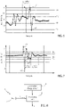
- step 44 a detection of a first peak p1 (positive or negative) is carried out in the filtered signal and, subsequently, a detection of a second peak p2 which is an inverted peak (negative or positive, respectively) is carried out.
- the peak p1 corresponds to a sample of the filtered signal S acc_filt that exceeds the negative threshold -Th (and therefore is hereinafter referred to as the negative peak)
- the peak p2, following p1 corresponds to a sample of the filtered signal S acc_filt that exceeds the positive threshold +Th (and therefore is hereinafter referred to as the positive peak) .
- the negative peak p1 is identified as a sample that exceeds the threshold -Th and which is immediately preceded and followed by respective samples p1' and p1" which have a value, in modulus, which is lower than the value, in modulus, of the negative peak p1.
- the positive peak p2 is identified as a sample that exceeds the threshold +Th and which is immediately preceded and followed by respective samples p2' and p2" which have a value, in modulus, which is lower than the value, in modulus, of the positive peak p2. It is noted that, in this example, the samples p1" and p2' coincide.
- the number of samples between the negative peak p1 and the positive peak p2 (in the example of Figure 5 , there is only one sample p1"/p2') is lower than a predefined maximum number, to better discriminate a "touch" event from an event of other type.
- this number of samples is equal to 2 (sampling the raw signal S acc_raw at 400Hz) or to multiples of 2 (sampling the raw signal S acc_raw at multiples of 400Hz) .
- Other values may be chosen as needed.
- Step 46 is described herein with graphic reference to Figure 6 , for improved clarity.
- Figure 6 the same notation of Figure 5 is used to identify the first peak (p1) and the inverted peak (p2) that exceed the preset thresholds ⁇ Th.
- a history buffer is used wherein a plurality of samples p_pre (temporally) preceding the first peak p1 are stored.
- this plurality of samples is a number equal to or greater than 8 (for example, 16 or 32), and includes the sample p1' and the other samples immediately preceding the sample p1'.
- the history buffer is analyzed, according to step 46, to verify a stationarity condition of the samples stored therein.
- the stationarity condition is verified if all the samples stored in the history buffer, or a subset thereof, are comprised between a positive threshold +Th' and a negative threshold -Th' (with
- the value in modulus of the thresholds ⁇ Th' is comprised between 0.0625 g and 2 g.
- the stationarity condition is assessed on the samples present in the history buffer except for a subset of samples immediately preceding the first peak p1 (for example the 2 samples immediately preceding the first peak p1).
- the Applicant has in fact verified that the signal relating to the touch includes the samples immediately preceding the peak.
- a plurality of samples following the second peak p2 are analyzed.
- this plurality of samples is a number equal to or greater than 8 (for example, 16 or 32), and includes the sample p2" and other samples immediately following the sample p2".
- the stationarity condition is verified if all the samples immediately following the second peak p2, or a subset thereof, are comprised between a positive threshold +Th" and a negative threshold -Th" (with
- the value in modulus of the thresholds ⁇ Th" is comprised between 0.0625 g and 2 g.
- the stationarity condition is assessed on a plurality of samples p_post following the second peak p2 except for a subset of samples p_excl immediately following the second peak p2 (e.g. excluding the 6-8 samples immediately following the second peak p2).
- a subset of samples p_excl immediately following the second peak p2 e.g. excluding the 6-8 samples immediately following the second peak p2.
- the Applicant has verified that in some practical conditions, in the event of a signal resulting from a "touch" (therefore the event to be detected), after the second peak p2 a step is observed wherein the oscillation of the signal of the accelerometer 4 persists for a limited time (similarly to a "rebound” effect). In this manner, the stationarity condition is assessed by excluding this settling step following the second peak p2.
- the first peak may indifferently be a negative or positive peak and, as a result, the second peak (inverted peak) is a positive or negative peak respectively.
- the stationarity verifications of steps 46 and 50 may be carried out both or one as an alternative to the other. For example, it is possible to provide for carrying out only the stationarity verification of step 46 and not the stationarity verification of step 50, or vice versa.
- the method of Figure 4 may also be used to identify a multiple touch event (e.g., double or triple touch), verifying the presence of a plurality of consecutive touch events in a predefined (and possibly configurable) period of time.
- a timer or counter usable to, after the occurrence of a touch event, count the number of samples that are present before the following touch event. If this number of samples is comprised in a predefined range (or lower than a maximum value) then the second touch event is correlated with the first touch event to validate the multiple touch event.
- the electronic system 1 comprises (e.g., integrates or accommodates in the case), in addition to the elements illustrated in Figure 1 and previously described, also an electrostatic charge variation sensor 6 operatively coupled to the processing unit 2.
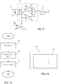
- FIG. 9 illustrates, by way of non-limiting example, an embodiment of the electrostatic charge variation sensor 6.
- the electrostatic charge variation sensor 6 comprises an input electrode 8, coupeable to a body portion of a user.
- the electrostatic charge variation sensor 6 of Figure 9 is configured to be placed in electrical or electrostatic contact with a body portion of a user, for detecting the touch.
- the user uses his/her finger, and in particular his/her fingertip, to perform the touch.
- the input electrode 8 forms part of a differential input 9 of an instrumentation amplifier 12.
- An input capacitor C I biased through a direct current (DC) generator G I and an input resistor R I connected in parallel with each other and with the input capacitor C I are at the ends of the differential input 9.
- DC direct current
- the voltage Vd across the input capacitor C I remains constant until the user touches the electrode 8; in this case, the voltage across the input capacitor C I varies due to the electric charge/discharge process through the user's body.
- the voltage Vd returns to its steady state value.
- the instrumentation amplifier 12 is essentially formed by two operational amplifiers OP1 and OP2.
- a biasing stage (buffer) OP3 is used to bias the instrumentation amplifier 12 to a common mode voltage V CM .
- the components of the amplifier 12 are chosen in such a way that the amplifier 12 has high impedance (of the order of 10 9 Ohm) in its passband (chosen between DC and 500 Hz).
- the voltage Vd across the input capacitor C I is detected by the amplifier 12.
- the differential output Vd' is therefore proportional to the potential Vd at input, and is provided at input to an analog-to-digital converter 14, which provides the charge variation signal S Q for the processing unit 2 at output.
- the charge variation signal S Q is, for example, a high-resolution digital stream (16 bits or 24 bits).
- the analog-to-digital converter 14 is optional, since the processing unit 2 may be configured to work directly on the analog signal, or may itself comprise an analog-to-digital converter for converting the signal Vd'.
- the amplifier stage 12 may be omitted, by feeding the signal directly to the input of the analog-to-digital converter.
- ADC analog-to-digital converter
- Figure 10 illustrates, through a flow chart, the operations carried out by the processing unit 2 to process the signal provided by the electrostatic charge variation sensor 6.
- the processing unit 2 receives, from the electrostatic charge variation sensor 6, the charge variation signal S Q .
- the signal S Q is, in the described embodiment, a digital signal.
- Figure 11 exemplarily illustrates the signal S Q generated following an event of contact between the input electrode 8 and the fingertip of a user (touch event).
- the values of the potential Vd, induced by the physical contact of the user with the input electrode 8, are represented on the ordinate axis of the charge variation signal S Q .
- This value is here expressed in LSB ("Least Significant Bit"), that is the minimum digital value output from the analog-to-digital converter, which is proportional to the voltage detected at the input electrode 8.
- LSB corresponds to a value comprised between a few ⁇ V and a few tens of ⁇ V.
- the constant of proportionality depends on the gain of the amplifier, on the resolution of the analog-to-digital converter and on any digital processing (e.g., oversampling, decimation, etc.) .
- the LSB representation is common in the art and disregards a quantification in physical units, as the aim is typically to detect relative variations, with respect to a steady or base state.
- the progressive numbers of the acquired sample are represented on the abscissa axis of the charge variation signal S Q .
- step 62 the processing unit 2 performs an operation of calculating or estimating the variance of the signal S Q , obtaining the variance signal S Q _ var .
- the calculation or estimation of the variance is carried out in a per se known manner, for example as described by Tony Finch in "Incremental calculation of weighted mean and variance", University of Cambridge Computing Service, February 2009 .
- Other methods may be used, such as for example, approaches based on IIR filters, or yet others.
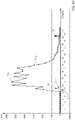
- Figure 12 illustrates the variance signal S Q_var , and the filtered accelerometer signal S acc_filt , superimposed to each other. It is noted that Figure 12 shows the square root of the signals S acc_filt and S Q _ var .
- the operation of calculating the square root of the variance value has the function of compressing the dynamics of the output signal, as well as of bringing it back to the initial physical dimension. In other words, the variance squares, the square root restores the physical dimensions. For example, if the physical dimension x of the input signal is [x] 2 ; after the variance it is [(x 2 )] 2 ; after the square root operation it returns to [x] 2 .
- step 64 a step of searching for a maximum point of the signal S Q is carried out.
- the maximum point corresponds, in this example wherein digital signals (samples) are used, to the sample whose value (on the ordinate axis) is the greatest with respect to a plurality of comparison samples.
- each sample is compared with the maximum value detected up to that instant and, if it is greater than the maximum value, the maximum value is updated to the value of the current sample. This operation is initiated (e.g., the maximum is reset to the current value) after the detection of a "shock" event by the accelerometer 4.
- the shock event considered is any event that causes the generation of a signal of the accelerometer 4 which, after having been filtered as previously described (e.g., high-pass filter or Slope filter), exceeds the threshold +Th (positive exceedance) or -Th (negative exceedance) .
- the exceedance of the threshold ⁇ Th is confirmed if at least one sample of the signal S acc_filt exceeds the threshold ⁇ Th.
- step 66 the confirmation of the occurred touch is awaited on the basis of the signal of the accelerometer 4 (e.g., the interrupt signal I S previously mentioned).
- this signal is generated at sample #90.
- the search for the maximum value of the signal S Q_var discussed in step 64 is thus interrupted.
- the final decision of the occurred touch is taken, as well as a function of the signal of the accelerometer 4, also as a function of the signal acquired by the electrostatic charge variation sensor 6 and processed as previously discussed.
- a current sample of the signal S Q_var is acquired (for the purposes of the present invention, this current sample is exemplarily the one at which the interrupt was received). The value of the current sample is compared to a threshold Th_Q.
- the touch event is confirmed and one or more functionalities correlated to this touch event (not object of the present invention) are activated.
- the threshold Th_Q is preset to a value chosen during the design step and in any case changeable (e.g., comprised between 8000 and 12000 LSB); this value is chosen on the basis of the sensor and electrode used, through laboratory tests.
- the value of the sample p MAX of the signal S Q_var is in said predefined relationship with this threshold (in particular, it exceeds the threshold Th_Q)
- a further comparison of the value of the current sample of the signal S Q_var with a second threshold Th_Q' chosen as a fraction of the maximum value of the previously identified signal S Q_var is carried out.
- the second threshold Th_Q' is equal to 1/4 of the maximum value of the signal S Q _ var .
- the aforementioned operations are carried out on the variance signal under square root (as previously said). Other embodiments are however possible.
- both comparisons with the thresholds Th_Q and Th_Q' comply with a respective predefined condition (in particular, the value of the sample p MAX of the signal S Q_var exceeds the threshold Th_Q and the current value of the signal S Q_var is lower than the threshold Th_Q'), then the touch event is confirmed and one or more functionalities correlated to this touch event (not object of the present invention) are activated.
- the use of the signal resulting from the electrostatic charge sensor 6 may also be used to detect a touch condition that persists over time, for example when the user performs the touch while holding the pressure for a continuous time of a few tenths of a second (e.g. 0.6 seconds).
- This event herein identified as a "long touch” may be used to activate further or different functionalities with respect to those that may be activated with a traditional, typically rapid, touch event.
- the long touch event is identified if the signal S Q_var remains above the threshold Th_Q for a time which is longer than a minimum time, predefined during the design step and in any case configurable as needed. It is apparent that the comparison threshold for the long touch may be a further threshold different from the thresholds Th_Q, for example chosen equal to 10000 LSB.
- Figure 13 illustrates an example of signal S Q_var that identifies a long touch.
- the method of Figure 10 may also be used to identify a multiple-touch event (e.g., double or triple touch), verifying the presence of a plurality of consecutive touch events in a predefined (and possibly configurable) period of time, similarly to what has been described hereinabove with reference to the method of Figure 4 .
- a multiple-touch event e.g., double or triple touch
- verifying the presence of a plurality of consecutive touch events in a predefined (and possibly configurable) period of time similarly to what has been described hereinabove with reference to the method of Figure 4 .
- FIG. 14 schematically illustrates an electronic device 100 which includes the previously described electronic system 1, according to any of the embodiments of the present invention.
- the electronic device 100 comprises a touch-sensitive surface 102 (detection surface), which is the surface at which the user performs the physical touch gesture.
- This surface is, for example, of plastic material, with a thickness of approximately 1 mm.
- the electronic system 1 is placed below the surface 102, for example accommodated in an own package.
- the relative arrangement between the surface 102 and the electronic system 1 meets one or more of the following parameters:
- the invention may be effectively implemented in all those devices wherein a mechanical contact cannot be present, or for impermeability, immunity to dust or mechanical strength requirements.
- Some examples smartphones, smartwatches, True Wireless Stereos (TWS), headsets, appliances, industrial equipment, etc.
- TWS True Wireless Stereos
- an accelerometer and, in the respective embodiment, of an electrostatic charge sensor allow the consumptions to be significantly reduced with respect to solutions that provide a sensor with a panel of "touch-screen” type.
- the solution described with reference to Figure 4 (detection of the stationarity before and/or after the detection of the first and second peaks) allows false positives to be significantly reduced.
- the solution that provides the use of the electrostatic charge sensor further improves the performances of rejections of false positives with respect to the solution with accelerometer only.
- the use of the electrostatic charge sensor expands the range of gestures that the user may use to give commands to the system 100 (e.g., the long touch).
- respective operations of filtering for example using low-pass or high-pass filters
- the filtering has the function of removing noise or non-significant frequency disturbing components, or low frequency components (e.g. gravity acceleration component or movements attributable to human activity for Sacc), from the signals S acc and S Q .
- low frequency components e.g. gravity acceleration component or movements attributable to human activity for Sacc
- processing of the signals of the accelerometer 4 and of the electrostatic charge sensor 6 may be implemented entirely in hardware, entirely in software or in mixed hardware/software form, as needed.
Landscapes
- Engineering & Computer Science (AREA)
- Theoretical Computer Science (AREA)
- General Engineering & Computer Science (AREA)
- Physics & Mathematics (AREA)
- Human Computer Interaction (AREA)
- General Physics & Mathematics (AREA)
- Computer Hardware Design (AREA)
- Acoustics & Sound (AREA)
- User Interface Of Digital Computer (AREA)
- Electronic Switches (AREA)
Abstract
Description
- The present invention relates to a system for detecting a touch gesture of a user, a device comprising the detection system, and a method for detecting a touch gesture of a user.
- Nowadays, one of the most important causes of malfunction of mobile devices, in particular cell phones, relates to mechanical buttons, which are subject to breakage due to structural weakness, use of fragile flexible PCBs, problems of water resistance, etc.
- The solutions, known to the Applicant, to mechanical buttons provide buttons based on capacitive sensors, particularly suitable for implementation on full-screen devices; however they are not always reliable as they are subject to disturbances resulting from the presence of environmental electrical charge.
- MEMS accelerometers are used to implement electronic buttons, as they are suitable for detecting movements resulted from the touch, or "tap", (or double tap) of the user, exploiting suitable algorithms that detect and process the acceleration data provided by these MEMS accelerometers. Even this solution, however, is subject to environmental or use conditions that may cause a false touch detection (for example due to accelerations resulting from movements of the user's body which are similar to a touch even if they are not such).
- In some devices that do not suffer from battery consumption in stand-by (for example because they have a large battery), it is possible to use the touch-screen technology to detect the touch gesture. This type of solution ensures high accuracy, but the implementation cost is high and, as said, requires a non-negligible energy consumption.
- In one embodiment known to the Applicant, the touch gesture is identified by processing and monitoring an acceleration signal or vibratory signal, provided by an accelerometer following a touch gesture, filtered through a high-pass filter. The high-pass filter is, in particular, configured to filter the low frequency signal components (e.g., acceleration due to gravity, movements attributable to human activity) and leave the high frequency signal components, including the signal components attributable to touch, unaltered. By way of non-limiting example, the high frequency components of interest for the present invention are higher than 50 Hz.
- The filtering is, in particular, obtained through a digital "Slope" filter. Therefore, with reference to
Figures 1A and 1B , the raw signal provided by the accelerometer (inFigure 1A , the signal Sacc_raw) is sampled (i.e., converted into digital); again inFigure 1A , the n-th sample at time tn is identified as acc(tn) and the sample immediately preceding time tn-1 is identified as acc(tn-1). -
Figure 1B illustrates the signal ofFigure 1A filtered through the Slope filter (filtered signal Sacc_filt). The n-th filtered sample is obtained according to the following formula:
- By setting a suitable threshold on the filtered signal, it is possible to identify possible touch events at the local exceedance of this threshold, by at least one sample of the filtered signal. The threshold may be of a fixed type (preset and/or configurable) or of adaptive type.
-
Figure 2 shows, by way of example, a further accelerometric signal, filtered with the Slope filter according to what has been described with reference toFigure 1B. Figure 2 also shows two thresholds (one positive +Th and one negative -Th). InFigure 2 , the exceedance of the threshold +Th occurs by two samples acc_filt(ti) and acc_filt(t11) in two respective time instants t1 and t11 and causes the generation of an interrupt event that identifies the occurred touch at the times t2 and t12 since the signal returns within the range defined by the thresholds -Th and +Th by a predefined time. - This technical solution has the advantage of requiring low energy consumption and low cost; furthermore, it allows to obtain high accuracy in the identification of any touch event, but at the same time generates a significant number of false positives, for example in cases wherein the accelerometer detects vibrations resulting from an unwanted touch in proximity to the device (for example on the strap of a smartwatch, and in other similar situations).
- The problems mentioned hereinabove are overcome by the solutions that provide the use of a touch sensor, which however, as said, has a high cost and significant energy consumption. Furthermore, the touch sensor technology is not applicable to any device (for example to earphones) due to the size and/or current consumption required for implementing a touch sensor.
- Patent document
US2010/060604 discloses an advanced technique of user interaction with compact, portable, handheld devices, larger electronic devices and other surfaces and objects. The particular component arrays, configuration modes and analytic methodologies disclosed are directed toward logical interpretation of device motions resulting from vector impulses as user data inputs and commands. - Patent document
US2010/256947 relates in general to a system and method in which a directional tap detection algorithm and a tri-axis accelerometer extend the number of unique buttonless inputs available for small mobile devices like cell phones and MP3 players. The algorithm analyzes acceleration data from the single accelerometer to detect the direction (X+, X-, Y+, Y-, Z+, Z-) and number (single or double) of taps, yielding 12 unique inputs. - Patent document
WO2010/045498 relates generally to motion sensing devices, and more specifically to recognizing motion gestures based on motion sensors of a motion sensing device. - Scientific publication by N. P. Kharaje, K. Fakir and S. Kodagali, "Digital pen for paralyzed patient," 2016 International Conference on Communication and Signal Processing (ICCSP), 2016, pp. 1908-1911, presents digital pen for handwritten digit and gesture trajectory recognition for paralyzed patient.
- Patent document
EP3402074 concerns a processor for processing the output of a proximity sensor, and a smart proximity sensor that is combined with a processor that is arranged to output a signal that discriminates between the proximity to a human body and the proximity to an inanimate object. - Patent document
WO2020/201341 relates to on-head detection of hearing devices, such as headsets or headphones. - Patent document
US2021/232227 , published after the filing date of the present application, relates to a system for detection of a touch gesture of a user on a detection surface. - However, the above-mentioned issues are not solved.
- The need is therefore felt to overcome the drawbacks of the prior art by providing a system for detecting a touch gesture of a user, a device comprising the detection system, and a method for detecting a touch gesture of a user which are enhanced.
- According to the present invention, a system for detecting a touch gesture of a user, a device comprising the detection system, and a method for detecting a touch gesture of a user are provided, as defined in the attached claims.
- In one embodiment, the system for detecting a touch gesture of a user on a detection surface comprises:
- a processing unit;
- an accelerometer, operatively coupled to the processing unit, configured to detect a vibration at said detection surface and generate a corresponding vibration signal, wherein the processing unit is configured to: acquire the vibration signal, detect, in the vibration signal, a signal characteristic which can be correlated to said touch gesture of the user, detect, in the vibration signal, a stationarity condition preceding and/or following said detected signal characteristic, and validate said touch gesture by the user in the event that both the signal characteristic and the stationarity condition preceding and/or following said signal characteristic have been detected.
- Furthermore, in one embodiment, the operation of detecting said signal characteristic comprises: calculating a filtered vibration signal by filtering, through a high-pass filter, the vibration signal; detecting a first peak of the filtered vibration signal exceeding a first threshold; and detecting a second peak of the filtered vibration signal exceeding a second threshold, wherein the first threshold is one of a positive threshold and a negative threshold, and the second threshold is the other of said positive threshold and said negative threshold.
- Furthermore, in one embodiment, the processing unit is further configured to sample the vibration signal, and the operation of calculating the filtered vibration signal is carried out using a digital filter, said operation of detecting the first peak comprising: detecting a first sample of the filtered vibration signal which exceeds the first threshold; detecting a second sample of the filtered vibration signal immediately preceding the first sample and having a value, in modulus, which is lower than the value, in modulus, of the first sample; and detecting a third sample of the filtered vibration signal immediately following the first sample and having a value, in modulus, which is lower than the value, in modulus, of the first sample, said first peak corresponding to the first sample.
- Furthermore, in one embodiment, said operation of detecting the second peak comprises: detecting a fourth sample of the filtered vibration signal which exceeds the second threshold; detecting a fifth sample of the filtered vibration signal immediately preceding the fourth sample and having a value, in modulus, which is lower than the value, in modulus, of the fourth sample; and detecting a sixth sample of the filtered vibration signal immediately following the fourth sample and having a value, in modulus, which is lower than the value, in modulus, of the fourth sample, said second peak corresponding to the fourth sample.
- Furthermore, in one embodiment, the operation of detecting said signal characteristic further comprises verifying that the first peak and the second peak are at a mutual distance, in terms of number of samples comprised between the first peak and the second peak, which is lower than a maximum value of number of samples.
- Furthermore, in one embodiment, the operation of detecting, in the vibration signal, a stationarity condition preceding said signal characteristic comprises: after detecting the first peak, verifying that the values of a first plurality of samples of the filtered vibration signal preceding the first peak are comprised in a first range of reference values.
- Furthermore, in one embodiment, the operation of detecting, in the vibration signal, a stationarity condition following said signal characteristic comprises: after detecting the second peak, verifying that the values of a second plurality of samples of the filtered vibration signal following the second peak are comprised in a second range of reference values.
- Furthermore, in one embodiment, the operation of detecting, in the vibration signal, a stationarity condition following said signal characteristic further comprises discarding a third plurality of samples of the filtered vibration signal immediately following the second peak and comprised between the second peak and said second plurality of samples of the filtered vibration signal.
- Furthermore, in one embodiment, the system further comprises an electrostatic charge variation sensor, operatively coupled to the processing unit, configured to detect an electrostatic charge variation at said detection surface and, as a result, generate a charge variation signal.
- Furthermore, in one embodiment, the processing unit is further configured to generate a variance signal by calculating the variance of the charge variation signal.
- Furthermore, in one embodiment, the processing unit is further configured to detect a maximum point of the variance signal when said signal characteristic which can be correlated to said touch gesture of the user is detected in the vibration signal.
- Furthermore, in one embodiment, the processing unit is further configured to: verify whether the maximum point of the variance signal is in a predefined relationship with a third threshold, and in the event that both the signal characteristic and the stationarity condition preceding and/or following said signal characteristic have been detected, validate said touch gesture only if the maximum point of the variance signal meets said predefined relationship with the third threshold.
- Furthermore, in one embodiment, the processing unit is further configured to: in the event that both the signal characteristic and the stationarity condition preceding and/or following said signal characteristic have been detected, and if the maximum point of the variance signal meets said predefined relationship with the third threshold, verify whether the variance signal is in a stationarity condition and validate said touch gesture only if the variance signal meets said stationarity condition.
- Furthermore, in one embodiment, the stationarity condition of the variance signal is met if at least one current sample of the variance signal has a value comprised within a range of stationarity reference values.
- Furthermore, one embodiment provides the step of detecting a touch event that persists over time if the variance signal remains above a fourth threshold for a time which is longer than a predefined touch time.
- The present invention also relates to a method for detecting a touch gesture of a user on a detection surface, using a system which comprises: a processing unit; and an accelerometer, operatively coupled to the processing unit, configured to detect a vibration at said detection surface and generate a corresponding vibration signal, the method comprising the steps, carried out by the processing unit, of: acquiring the vibration signal, detecting, in the vibration signal, a signal characteristic which can be correlated to said touch gesture of the user, detecting, in the vibration signal, a stationarity condition preceding and/or following said detected signal characteristic, and validating said touch gesture by the user in the event that both the signal characteristic and the stationarity condition preceding and/or following said signal characteristic have been detected.
- Furthermore, in one embodiment, the step of detecting said signal characteristic comprises: calculating a filtered vibration signal by filtering, through a high-pass filter, the vibration signal; detecting a first peak of the filtered vibration signal exceeding a first threshold; and detecting a second peak of the filtered vibration signal exceeding a second threshold, wherein the first threshold is one of a positive threshold and a negative threshold, and the second threshold is the other of said positive threshold and said negative threshold.
- Furthermore, in one embodiment, the method comprises the step of sampling the vibration signal, and wherein the step of calculating the filtered vibration signal is carried out using a digital filter, said step of detecting the first peak comprising: detecting a first sample of the filtered vibration signal that exceeds the first threshold; detecting a second sample of the filtered vibration signal immediately preceding the first sample and having a value, in modulus, which is lower than the value, in modulus, of the first sample; and detecting a third sample of the filtered vibration signal immediately following the first sample and having a value, in modulus, which is lower than the value, in modulus, of the first sample, said first peak being chosen corresponding to the first sample.
- Furthermore, in one embodiment, the step of detecting the second peak comprises: detecting a fourth sample of the filtered vibration signal that exceeds the second threshold; detecting a fifth sample of the filtered vibration signal immediately preceding the fourth sample and having a value, in modulus, which is lower than the value, in modulus, of the fourth sample; and detecting a sixth sample of the filtered vibration signal immediately following the fourth sample and having a value, in modulus, which is lower than the value, in modulus, of the fourth sample, said second peak being chosen corresponding to the fourth sample.
- Furthermore, in one embodiment, the step of detecting said signal characteristic further comprises verifying that the first peak and the second peak are at a mutual distance, in terms of number of samples comprised between the first peak and the second peak, which is lower than a maximum value of number of samples.
- Furthermore, in one embodiment, the step of detecting, in the vibration signal, a stationarity condition preceding said signal characteristic comprises: after detecting the first peak, verifying that the values of a first plurality of samples of the filtered vibration signal preceding the first peak are comprised in a first range of reference values.
- Furthermore, in one embodiment, the step of detecting, in the vibration signal, a stationarity condition following said signal characteristic comprises: after detecting the second peak, verifying that the values of a second plurality of samples of the filtered vibration signal following the second peak (p2) are comprised in a second range of reference values.
- Furthermore, in one embodiment, the step of detecting, in the vibration signal, a stationarity condition following said signal characteristic further comprises discarding a third plurality of samples of the filtered vibration signal immediately following the second peak and comprised between the second peak and said second plurality of samples of the filtered vibration signal.
- Furthermore, in one embodiment, wherein said system further comprises an electrostatic charge variation sensor, operatively coupled to the processing unit, the method further comprising the steps of detecting, through the electrostatic charge variation sensor, an electrostatic charge variation at said detection surface and generating as a result, through the electrostatic charge variation sensor, a charge variation signal.
- Furthermore, in one embodiment, the method further comprises the step of generating a variance signal by calculating the variance of the charge variation signal.
- Furthermore, in one embodiment, the method further comprises the step of detecting a maximum point of the variance signal when said signal characteristic which can be correlated to said touch gesture of the user is detected in the vibration signal.
- Furthermore, in one embodiment, the method further comprises: verifying whether the maximum point of the signal of (SQ_var) is in a predefined relationship with a third threshold, and in the event that both the signal characteristic and the stationarity condition preceding and/or following said signal characteristic have been detected, validating said touch gesture only if the maximum point of the variance signal meets said predefined relationship with the third threshold.
- Furthermore, in one embodiment, the method further comprises: in the event that both the signal characteristic and the stationarity condition preceding and/or following said signal characteristic have been detected, and if the maximum point of the variance signal meets said predefined relationship with the third threshold, verifying whether the variance signal is in a stationarity condition and validating said touch gesture only if the variance signal meets said stationarity condition.
- Furthermore, in one embodiment, the stationarity condition of the variance signal is met if at least one current sample of the variance signal has a value comprised within a range of stationarity reference values.
- Furthermore, in one embodiment, the method further comprises the step of detecting a touch event that persists over time if the variance signal remains above a fourth threshold for a time which is longer than a predefined touch time.
- For a better understanding of the invention, embodiments thereof are now described, purely by way of non-limiting example and with reference to the attached drawings, wherein:
-
Figure 1A illustrates a vibrational signal generated by an accelerometer following a movement; -
Figure 1B illustrates the signal ofFigure 1a after a filtering step with a high-pass filter, according to the prior art; -
Figure 2 illustrates a further signal generated by an accelerometer, filtered with the filter described with reference toFigure 1B , wherein a touch event by a user is identified on the basis of the exceedance of predefined thresholds, according to the prior art; -
Figure 3 schematically illustrates an electronic or electromechanical system or chip or package, according to an aspect of the present invention; -
Figure 4 illustrates a method for detecting a touch gesture exploiting a vibratory signal of an accelerometer, according to an aspect of the present invention; -
Figures 5-7 graphically illustrate respective steps of the method ofFigure 4 ; -
Figure 8 illustrates the electronic or electromechanical system or chip or package ofFigure 3 further comprising an electrostatic charge sensor, according to a further aspect of the present invention; -
Figure 9 illustrates an embodiment of an electrostatic charge sensor, which can be used in the system ofFigure 8 ; -
Figure 10 illustrates a method for detecting a touch gesture exploiting a vibratory signal of an accelerometer and an electrostatic charge variation signal of the sensor ofFigure 9 , according to an aspect of the present invention; -
Figures 11 and12 graphically illustrate respective steps of the method ofFigure 10 ; -
Figure 13 graphically illustrates an electrostatic charge variation signal generated by a touch prolonged over time of a detection electrode of the electrostatic charge sensor ofFigure 9 ; and -
Figure 14 illustrates an electronic device including the electronic or electromechanical system or chip or package ofFigure 3 orFigure 8 . -
Figure 3 illustrates, schematically and with thereference number 1, an electronic or electromechanical system or chip or package, according to an aspect of the present invention. Hereinafter, this system or chip orpackage 1 will be referred to as "electronic system" without thereby losing generality. Theelectronic system 1 comprises (e.g., integrates or accommodates in a case) aprocessing unit 2 and anaccelerometer 4 which is operatively coupled to theprocessing unit 2. - The
accelerometer 4 is configured to detect at least one acceleration component along an acceleration axis orthogonal to a detection surface (see for example, inFigure 14 , the surface 102). The detection surface is a surface at which a user causes a vibration by touching this surface with, for example, his/her finger (touch event or touch). For example, theaccelerometer 4 is of triaxial type, configured to detect acceleration components along three axes X, Y, Z orthogonal to each other; for detecting the touch, it is possible to choose the Z axis as the only detection axis, or otherwise choose any combination of two or more axes, possibly attributing a greater weight to one of them. - It is noted that the electronic system 1 (and therefore the accelerometer 4) may be installed or used with any orientation with respect to the Earth's gravitational axis, and therefore the
accelerometer 4 may be oriented in such a way as not to have the vertical detection axis (Z axis) necessarily in the direction of the force of gravity. Therefore, the detection axis of the force impressed by the touch may be chosen orthogonal to the sensor itself or along the assumed direction of the touch (on the basis of the modes in which theelectronic system 1 is installed or operates or is expected to operate); this also allows any unwanted impulses, which would come from other directions, to be filtered out. - As an alternative to the above, it is also possible, in a further embodiment, to consider a suitable vector composition of the three detection axes of the
accelerometer 4, to maximize the signal in the direction of the impressed force. - The
processing unit 2 receives an acceleration signal, or vibration signal, Sacc_raw (raw signal) from theaccelerometer 4 and generates, according to the acceleration signal Sacc_raw, a touch detection signal IS (e.g., an interrupt signal) by a user. - The
accelerometer 4 is for example an integrated sensor of semiconductor material, made using MEMS technology, of a per se known type and thereby not described in detail. - The
processing unit 2 is for example a microcontroller or an MLC (Machine Learning Core) residing in the ASIC (Application Specific Integrated Circuit) integrated in the MEMS, or a microprocessor of other type. - The
electronic system 1 may be a stand-alone system or alternatively be part, for example, of a printed circuit, or even be part of a more complex device or system. In fact, it is possible to provide a device or system that integrates a combo of sensors, and therefore in addition to the three axes X, Y, Z of theaccelerometer 4, there may also exist dedicated channels for other detections (e.g., gyroscope, temperature sensor, etc.). -
Figure 4 illustrates, through a flow chart, steps of a method for detecting the touch implemented by theelectronic system 1, in particular by theprocessing unit 2, according to an aspect of the present invention. - With reference to step 40, the
processing unit 2 receives and acquires, from theaccelerometer 4, the raw signal Sacc_raw generated by theaccelerometer 4, for example the signal Sacc_raw ofFigure 1A . Then, step 42, theprocessing unit 2 carries out an operation of filtering the raw signal Sacc_raw through a high-pass filter; in particular, the filtering operation is carried out through the Slope filter described with reference toFigure 1B , obtaining the filtered signal Sacc_filt. The filtered signal Sacc_filt is for example the signal ofFigure 1B, or Figure 2 , orFigure 5 (orFigure 6, or Figure 7 wherein filtered signals resulting from events other than the touch event are illustrated). - Then, step 44, a detection of a first peak p1 (positive or negative) is carried out in the filtered signal and, subsequently, a detection of a second peak p2 which is an inverted peak (negative or positive, respectively) is carried out. In this regard see
Figure 5 , wherein the peak p1 corresponds to a sample of the filtered signal Sacc_filt that exceeds the negative threshold -Th (and therefore is hereinafter referred to as the negative peak), whereas the peak p2, following p1, corresponds to a sample of the filtered signal Sacc_filt that exceeds the positive threshold +Th (and therefore is hereinafter referred to as the positive peak) . - In one embodiment of the present invention, the negative peak p1 is identified as a sample that exceeds the threshold -Th and which is immediately preceded and followed by respective samples p1' and p1" which have a value, in modulus, which is lower than the value, in modulus, of the negative peak p1. Similarly, the positive peak p2 is identified as a sample that exceeds the threshold +Th and which is immediately preceded and followed by respective samples p2' and p2" which have a value, in modulus, which is lower than the value, in modulus, of the positive peak p2. It is noted that, in this example, the samples p1" and p2' coincide.
- It is apparent that the conditions expressed hereinabove may be modified, for example by requiring a plurality of samples that precede and/or follow the positive p2 or negative peak p1 and having respective values which are lower in modulus than the value reached by the peak p1 or p2.
- In one embodiment, the number of samples between the negative peak p1 and the positive peak p2 (in the example of
Figure 5 , there is only one sample p1"/p2') is lower than a predefined maximum number, to better discriminate a "touch" event from an event of other type. For example, this number of samples is equal to 2 (sampling the raw signal Sacc_raw at 400Hz) or to multiples of 2 (sampling the raw signal Sacc_raw at multiples of 400Hz) . Other values may be chosen as needed. - Returning to
Figure 4 , a stationarity condition of the filtered signal Sacc_filt preceding the first peak p1 is detected instep 46. In particular, this step aims to detect whether the first peak detected is caused by an actual touch event or is caused by a more complex "shock" event, such as for example a shaking situation of theelectronic system 1 that accommodates theaccelerometer 4. In fact, in the case of shaking, there is a continuous perturbation of the signal of theaccelerometer 4, which may also result in the generation of one or more peaks that exceed the preset thresholds ±Th, such as for example illustrated inFigure 6 . -
Step 46 is described herein with graphic reference toFigure 6 , for improved clarity. InFigure 6 the same notation ofFigure 5 is used to identify the first peak (p1) and the inverted peak (p2) that exceed the preset thresholds ±Th. To discriminate between touch events and events of other type, such as for example shaking, according to an aspect of the present invention, a history buffer is used wherein a plurality of samples p_pre (temporally) preceding the first peak p1 are stored. In particular, this plurality of samples is a number equal to or greater than 8 (for example, 16 or 32), and includes the sample p1' and the other samples immediately preceding the sample p1'. When the first peak p1 is detected (according to what has been previously discussed), the history buffer is analyzed, according to step 46, to verify a stationarity condition of the samples stored therein. In particular, the stationarity condition is verified if all the samples stored in the history buffer, or a subset thereof, are comprised between a positive threshold +Th' and a negative threshold -Th' (with |+Th'|<|+Th| and |-Th' |<|-Th|). For example, the value in modulus of the thresholds ±Th' is comprised between 0.0625 g and 2 g. - In one embodiment, the stationarity condition is assessed on the samples present in the history buffer except for a subset of samples immediately preceding the first peak p1 (for example the 2 samples immediately preceding the first peak p1). The Applicant has in fact verified that the signal relating to the touch includes the samples immediately preceding the peak.
- In
step 48 the second peak p2 (inverted peak) is sought and, if any, detected, according to what has already been previously discussed. - In step 50 a stationarity condition of the filtered signal Sacc_filt following the second peak p2 is detected. In particular, this step aims to detect whether the second peak p2 detected is caused by an actual touch event or is caused by a more complex "shock" event, such as for example a clapping situation, which persists for a certain period of time, and which causes the generation of an accelerometric signal wherein a series of positive and negative above-threshold peaks (similar to the sequence of the first peak p1 and the second peak p2) are followed by a plurality of further peaks or a high noise signal, as for example illustrated in
Figure 7 (wherein the same notation ofFigure 5 is used to identify the first peak p1 and the inverted peak p2). - Therefore, in order to identify this situation, as said generated for example by clapping hands, according to an aspect of the present invention, a plurality of samples following the second peak p2 are analyzed.
- In particular, this plurality of samples is a number equal to or greater than 8 (for example, 16 or 32), and includes the sample p2" and other samples immediately following the sample p2". In particular, the stationarity condition is verified if all the samples immediately following the second peak p2, or a subset thereof, are comprised between a positive threshold +Th" and a negative threshold -Th" (with |+Th"|<|+Th| and |-Th"|<|-Th|). For example, the value in modulus of the thresholds ±Th" is comprised between 0.0625 g and 2 g.
- In one embodiment, the stationarity condition is assessed on a plurality of samples p_post following the second peak p2 except for a subset of samples p_excl immediately following the second peak p2 (e.g. excluding the 6-8 samples immediately following the second peak p2). In fact, the Applicant has verified that in some practical conditions, in the event of a signal resulting from a "touch" (therefore the event to be detected), after the second peak p2 a step is observed wherein the oscillation of the signal of the
accelerometer 4 persists for a limited time (similarly to a "rebound" effect). In this manner, the stationarity condition is assessed by excluding this settling step following the second peak p2. - The method described with reference to
Figure 4 may be modified as needed. In particular, the first peak may indifferently be a negative or positive peak and, as a result, the second peak (inverted peak) is a positive or negative peak respectively. Furthermore, the stationarity verifications ofsteps step 46 and not the stationarity verification ofstep 50, or vice versa. - Furthermore, the method of
Figure 4 may also be used to identify a multiple touch event (e.g., double or triple touch), verifying the presence of a plurality of consecutive touch events in a predefined (and possibly configurable) period of time. To this end, it is possible to use a timer or counter usable to, after the occurrence of a touch event, count the number of samples that are present before the following touch event. If this number of samples is comprised in a predefined range (or lower than a maximum value) then the second touch event is correlated with the first touch event to validate the multiple touch event. - In a further embodiment of the present invention, illustrated in
Figure 8 , theelectronic system 1 comprises (e.g., integrates or accommodates in the case), in addition to the elements illustrated inFigure 1 and previously described, also an electrostatic charge variation sensor 6 operatively coupled to theprocessing unit 2. -
Figure 9 illustrates, by way of non-limiting example, an embodiment of the electrostatic charge variation sensor 6. The electrostatic charge variation sensor 6 comprises an input electrode 8, coupeable to a body portion of a user. In particular, the electrostatic charge variation sensor 6 ofFigure 9 is configured to be placed in electrical or electrostatic contact with a body portion of a user, for detecting the touch. Typically, the user uses his/her finger, and in particular his/her fingertip, to perform the touch. - The input electrode 8 forms part of a
differential input 9 of aninstrumentation amplifier 12. - An input capacitor CI, biased through a direct current (DC) generator GI and an input resistor RI connected in parallel with each other and with the input capacitor CI are at the ends of the
differential input 9. In use, the voltage Vd across the input capacitor CI remains constant until the user touches the electrode 8; in this case, the voltage across the input capacitor CI varies due to the electric charge/discharge process through the user's body. In presence of a touch event and consequently after a transient (the duration thereof being defined by the constant RC of the parallel between capacitor CI and resistor RI) the voltage Vd returns to its steady state value. - The
instrumentation amplifier 12 is essentially formed by two operational amplifiers OP1 and OP2. A biasing stage (buffer) OP3 is used to bias theinstrumentation amplifier 12 to a common mode voltage VCM. - The inverting terminals of the operational amplifiers OP1 and OP2 are connected to each other through a resistor R2. Since the two inputs of each operational amplifier OP1, OP2 are to be at the same potential, the input voltage Vd is also applied across R2 and causes, through this resistor R2, a current equal to I2=Vd/R2. This current I2 does not come from the input terminals of the operational amplifiers OP1, OP2 and therefore flows through the two resistors R1 connected between the outputs of the operational amplifiers OP1, OP2, in series with the resistor R2; the current I2, thus flowing through the series of the three resistors R1-R2-R1, produces an output voltage Vd' given by Vd'=I2·(2R1+R2)=Vd·(1+2R1/R2). Therefore, the overall gain of the circuit of
Figure 9 is Ad=(1+2R1/R2). The differential gain depends on the value of the resistor R2 and may therefore be modified by acting on the resistor R2. - The components of the
amplifier 12 are chosen in such a way that theamplifier 12 has high impedance (of the order of 109 Ohm) in its passband (chosen between DC and 500 Hz). - The voltage Vd across the input capacitor CI is detected by the
amplifier 12. - The differential output Vd' is therefore proportional to the potential Vd at input, and is provided at input to an analog-to-
digital converter 14, which provides the charge variation signal SQ for theprocessing unit 2 at output. The charge variation signal SQ is, for example, a high-resolution digital stream (16 bits or 24 bits). - According to an embodiment, the analog-to-
digital converter 14 is optional, since theprocessing unit 2 may be configured to work directly on the analog signal, or may itself comprise an analog-to-digital converter for converting the signal Vd'. - According to a different embodiment, having an analog-to-digital converter (ADC) with suitable characteristics (e.g. differential input, high input impedance, high resolution, dynamic range optimized for the quantities to be measured, low noise) the
amplifier stage 12 may be omitted, by feeding the signal directly to the input of the analog-to-digital converter. -
Figure 10 illustrates, through a flow chart, the operations carried out by theprocessing unit 2 to process the signal provided by the electrostatic charge variation sensor 6. - With reference to step 60, the
processing unit 2 receives, from the electrostatic charge variation sensor 6, the charge variation signal SQ. The signal SQ is, in the described embodiment, a digital signal.Figure 11 exemplarily illustrates the signal SQ generated following an event of contact between the input electrode 8 and the fingertip of a user (touch event). The values of the potential Vd, induced by the physical contact of the user with the input electrode 8, are represented on the ordinate axis of the charge variation signal SQ. This value is here expressed in LSB ("Least Significant Bit"), that is the minimum digital value output from the analog-to-digital converter, which is proportional to the voltage detected at the input electrode 8. Typically 1 LSB corresponds to a value comprised between a few µV and a few tens of µV. The constant of proportionality (or sensitivity) depends on the gain of the amplifier, on the resolution of the analog-to-digital converter and on any digital processing (e.g., oversampling, decimation, etc.) . The LSB representation is common in the art and disregards a quantification in physical units, as the aim is typically to detect relative variations, with respect to a steady or base state. The progressive numbers of the acquired sample are represented on the abscissa axis of the charge variation signal SQ. - Then, step 62, the
processing unit 2 performs an operation of calculating or estimating the variance of the signal SQ, obtaining the variance signal SQ_var. The calculation or estimation of the variance is carried out in a per se known manner, for example as described by Tony Finch in "Incremental calculation of weighted mean and variance", University of Cambridge Computing Service, February 2009. Other methods may be used, such as for example, approaches based on IIR filters, or yet others. -
Figure 12 illustrates the variance signal SQ_var, and the filtered accelerometer signal Sacc_filt, superimposed to each other. It is noted thatFigure 12 shows the square root of the signals Sacc_filt and SQ_var. The operation of calculating the square root of the variance value has the function of compressing the dynamics of the output signal, as well as of bringing it back to the initial physical dimension. In other words, the variance squares, the square root restores the physical dimensions. For example, if the physical dimension x of the input signal is [x]2; after the variance it is [(x2)]2; after the square root operation it returns to [x]2. - Then, step 64, a step of searching for a maximum point of the signal SQ is carried out. The maximum point corresponds, in this example wherein digital signals (samples) are used, to the sample whose value (on the ordinate axis) is the greatest with respect to a plurality of comparison samples. In particular, each sample is compared with the maximum value detected up to that instant and, if it is greater than the maximum value, the maximum value is updated to the value of the current sample. This operation is initiated (e.g., the maximum is reset to the current value) after the detection of a "shock" event by the
accelerometer 4. The shock event considered is any event that causes the generation of a signal of theaccelerometer 4 which, after having been filtered as previously described (e.g., high-pass filter or Slope filter), exceeds the threshold +Th (positive exceedance) or -Th (negative exceedance) . The exceedance of the threshold ±Th is confirmed if at least one sample of the signal Sacc_filt exceeds the threshold ±Th. - In
Figure 12 , it is the sample #28 of the signal Sacc_filt that negatively exceeds the threshold -Th (first peak p1). This event triggers the search for the maximum of the signal SQ_var . At sample #28, the maximum value is reset to the current value of the signal SQ_var. Therefore, from the corresponding sample #28 (or alternatively from the subsequent, the sample #29) of the signal SQ_var, it is assessed whether this sample has a value (here, in LSB) which is greater than the maximum value calculated up to that instant. This operation continues until the detection of an actual touch signal, as described hereinafter in the following step 66. The maximum value assumed by the SQ_var is saved in memory. In the example ofFigure 12 , the sample having the maximum value was found at the sample #36 of the signal SQ_var (sample pMAX) . - Then, step 66, the confirmation of the occurred touch is awaited on the basis of the signal of the accelerometer 4 (e.g., the interrupt signal IS previously mentioned). In
Figure 12 , this signal is generated at sample #90. The search for the maximum value of the signal SQ_var discussed instep 64 is thus interrupted. - In this embodiment, the final decision of the occurred touch is taken, as well as a function of the signal of the
accelerometer 4, also as a function of the signal acquired by the electrostatic charge variation sensor 6 and processed as previously discussed. In particular, upon receiving the interrupt signal Is, a current sample of the signal SQ_var is acquired (for the purposes of the present invention, this current sample is exemplarily the one at which the interrupt was received). The value of the current sample is compared to a threshold Th_Q. - In one embodiment, if the value of the sample pmax of the signal SQ_var is in a predefined relationship with this threshold (in particular, it exceeds the threshold Th_Q) the touch event is confirmed and one or more functionalities correlated to this touch event (not object of the present invention) are activated. The threshold Th_Q is preset to a value chosen during the design step and in any case changeable (e.g., comprised between 8000 and 12000 LSB); this value is chosen on the basis of the sensor and electrode used, through laboratory tests.
- In a further embodiment, if the value of the sample pMAX of the signal SQ_var is in said predefined relationship with this threshold (in particular, it exceeds the threshold Th_Q), then a further comparison of the value of the current sample of the signal SQ_var with a second threshold Th_Q' chosen as a fraction of the maximum value of the previously identified signal SQ_var (i.e., in this example, that found at the sample #36) is carried out. For example, the second threshold Th_Q' is equal to 1/4 of the maximum value of the signal SQ_var. In this embodiment, the aforementioned operations are carried out on the variance signal under square root (as previously said). Other embodiments are however possible. If both comparisons with the thresholds Th_Q and Th_Q' comply with a respective predefined condition (in particular, the value of the sample pMAX of the signal SQ_var exceeds the threshold Th_Q and the current value of the signal SQ_var is lower than the threshold Th_Q'), then the touch event is confirmed and one or more functionalities correlated to this touch event (not object of the present invention) are activated.
- In a further embodiment, additional or alternative to those previously described, the use of the signal resulting from the electrostatic charge sensor 6 may also be used to detect a touch condition that persists over time, for example when the user performs the touch while holding the pressure for a continuous time of a few tenths of a second (e.g. 0.6 seconds). This event, herein identified as a "long touch", may be used to activate further or different functionalities with respect to those that may be activated with a traditional, typically rapid, touch event.
- The long touch event is identified if the signal SQ_var remains above the threshold Th_Q for a time which is longer than a minimum time, predefined during the design step and in any case configurable as needed. It is apparent that the comparison threshold for the long touch may be a further threshold different from the thresholds Th_Q, for example chosen equal to 10000 LSB.
Figure 13 illustrates an example of signal SQ_var that identifies a long touch. - Furthermore, the method of
Figure 10 may also be used to identify a multiple-touch event (e.g., double or triple touch), verifying the presence of a plurality of consecutive touch events in a predefined (and possibly configurable) period of time, similarly to what has been described hereinabove with reference to the method ofFigure 4 . -
Figure 14 schematically illustrates anelectronic device 100 which includes the previously describedelectronic system 1, according to any of the embodiments of the present invention. - For example, the
electronic device 100 comprises a touch-sensitive surface 102 (detection surface), which is the surface at which the user performs the physical touch gesture. This surface is, for example, of plastic material, with a thickness of approximately 1 mm. Theelectronic system 1 is placed below thesurface 102, for example accommodated in an own package. - In order to optimize the generation of both signals SQ and Sacc, it is preferable, but not necessary, that the relative arrangement between the
surface 102 and theelectronic system 1 meets one or more of the following parameters: - the sensors for detecting the acceleration and the charge variation are arranged as proximate as possible to the area identified as the touch surface; and
- the sensors for detecting the acceleration and the charge variation are placed proximate to each other, to optimize the correlation of the respective signals.
- The invention may be effectively implemented in all those devices wherein a mechanical contact cannot be present, or for impermeability, immunity to dust or mechanical strength requirements. Some examples: smartphones, smartwatches, True Wireless Stereos (TWS), headsets, appliances, industrial equipment, etc.
- The advantages achieved by the present invention are apparent from the previous description.
- In particular, the use of an accelerometer and, in the respective embodiment, of an electrostatic charge sensor allow the consumptions to be significantly reduced with respect to solutions that provide a sensor with a panel of "touch-screen" type.
- Furthermore, the solution described with reference to
Figure 4 (detection of the stationarity before and/or after the detection of the first and second peaks) allows false positives to be significantly reduced. The solution that provides the use of the electrostatic charge sensor further improves the performances of rejections of false positives with respect to the solution with accelerometer only. - Furthermore, the use of the electrostatic charge sensor expands the range of gestures that the user may use to give commands to the system 100 (e.g., the long touch).
- Variations and modifications may be applied to the present invention, without departing from the scope identified by the claims.
- For example, respective operations of filtering (for example using low-pass or high-pass filters) the signals Sacc and SQ may be provided. In particular, the filtering has the function of removing noise or non-significant frequency disturbing components, or low frequency components (e.g. gravity acceleration component or movements attributable to human activity for Sacc), from the signals Sacc and SQ.
- Furthermore, the processing of the signals of the
accelerometer 4 and of the electrostatic charge sensor 6 may be implemented entirely in hardware, entirely in software or in mixed hardware/software form, as needed.
Claims (23)
- A system (1) for detecting a touch gesture of a user on a detection surface (102), the system comprising:- a processing unit (2);- an accelerometer (4), operatively coupled to the processing unit (2), configured to detect a vibration at said detection surface (102) and generate a corresponding vibration signal (Sacc_raw),wherein the processing unit (2) is configured to:acquire the vibration signal (Sacc_raw),detect, in the vibration signal (Sacc_raw, Sacc_filt) , a signal characteristic (p1, p2) which can be correlated to said touch gesture of the user,detect, in the vibration signal (Sacc_raw, Sacc_filt) , a stationarity condition preceding and/or following said detected signal characteristic, andvalidate said touch gesture by the user in the event that both the signal characteristic and the stationary condition preceding and/or following said signal characteristic have been detected.
- The system according to claim 1, wherein the operation of detecting said signal characteristic (p1, p2) comprises:calculating a filtered vibration signal (Sacc_filt) by filtering, through a high-pass filter, the vibration signal (Sacc_raw) ;detecting a first peak (p1) of the filtered vibration signal (Sacc_filt) exceeding a first threshold (-Th; +Th); anddetecting a second peak (p2) of the filtered vibration signal (Sacc_filt) exceeding a second threshold (+Th; -Th),wherein the first threshold is one of a positive threshold and a negative threshold, and the second threshold is the other of said positive threshold and said negative threshold.
- The system according to claim 2, wherein the processing unit (2) is further configured to sample the vibration signal (Sacc_raw), and the operation of calculating the filtered vibration signal (Sacc_filt) is carried out using a digital filter,said operation of detecting the first peak comprising: detecting a first sample (p1) of the filtered vibration signal (Sacc_filt) which exceeds the first threshold; detecting a second sample (p1') of the filtered vibration signal (Sacc_filt) immediately preceding the first sample (p1) and having a value, in modulus, which is lower than the value, in modulus, of the first sample (p1); and detecting a third sample (p1") of the filtered vibration signal (Sacc_filt) immediately following the first sample (p1) and having a value, in modulus, which is lower than the value, in modulus, of the first sample (p1),said first peak corresponding to the first sample (p1).
- The system according to claim 3, wherein said operation of detecting the second peak (p2) comprises: detecting a fourth sample (p2) of the filtered vibration signal (Sacc_filt) which exceeds the second threshold; detecting a fifth sample (p2') of the filtered vibration signal (Sacc_filt) immediately preceding the fourth sample (p2) and having a value, in modulus, which is lower than the value, in modulus, of the fourth sample (p2); and detecting a sixth sample (p2") of the filtered vibration signal (Sacc_filt) immediately following the fourth sample (p2) and having a value, in modulus, which is lower than the value, in modulus, of the fourth sample (p2),
said second peak corresponding to the fourth sample (p2) . - The system according to anyone of claims 2-4, wherein the operation of detecting said signal characteristic (p1, p2) further comprises verifying that the first peak (p1) and the second peak (p2) are at a mutual distance, in terms of number of samples comprised between the first peak (p1) and the second peak (p2), which is lower than a maximum value of number of samples.
- The system according to anyone of claims 2-5, wherein the operation of detecting, in the vibration signal (Sacc_raw, Sacc_filt), the stationarity condition preceding said signal characteristic (p1, p2) comprises:
after detecting the first peak (p1),verifying that the values of a first plurality of samples (p_pre) of the filtered vibration signal (Sacc_filt) preceding the first peak (p1) are comprised in a first range of reference values (±Th') . - The system according to claim 6, wherein said operation of detecting, in the vibration signal (Sacc_raw, Sacc_filt), a stationarity condition preceding said signal characteristic (p1, p2) further comprises discarding, from the first plurality of samples (p_pre), a first intermediate sample immediately preceding the first peak (p1) and a second intermediate sample immediately preceding the first intermediate sample.
- The system according to anyone of claims 2-7, wherein the operation of detecting, in the vibration signal (Sacc_raw, Sacc_filt), a stationarity condition following said signal characteristic (p1, p2) comprises:
after detecting the second peak (p2), verifying that the values of a second plurality of samples (p_post) of the filtered vibration signal (Sacc_filt) following the second peak (p2) are comprised in a second range of reference values (±Th") . - The system according to claim 8, wherein the operation of detecting, in the vibration signal (Sacc_raw, Sacc_filt), a stationarity condition following said signal characteristic (p1, p2) further comprises discarding a third plurality of samples (p_excl) of the filtered vibration signal (Sacc_filt) immediately following the second peak (p2) and comprised between the second peak (p2) and said second plurality of samples of the filtered vibration signal (Sacc_filt) .
- The system according to anyone of the preceding claims, further comprising an electrostatic charge variation sensor (6), operatively coupled to the processing unit (2), configured to detect an electrostatic charge variation at said detection surface and, as a result, generate a charge variation signal (SQ).
- The system according to claim 10, wherein the processing unit (2) is further configured to generate a variance signal (SQ_var) by calculating the variance of the charge variation signal (SQ).
- The system according to claim 11, wherein the processing unit (2) is further configured to detect a maximum point (pMAX) of the variance signal (SQ_var) when said signal characteristic which can be correlated to said touch gesture of the user is detected in the vibration signal (Sacc_raw, Sacc_filt).
- The system according to claim 12, wherein the processing unit (2) is further configured to:verify whether the maximum point (pMAX) of the variance signal (SQ_var) is in a predefined relationship with a third threshold, andin the event that both the signal characteristic and the stationarity condition preceding and/or following said signal characteristic have been detected, validate said touch gesture only if the maximum point (pMAX) of the variance signal (SQ_var) meets said predefined relationship with the third threshold.
- The system according to claim 12, wherein the processing unit (2) is further configured to:
in the event that both the signal characteristic and the stationarity condition preceding and/or following said signal characteristic have been detected, and if the maximum point (pMAX) of the variance signal (SQ_var) meets said predefined relationship with the third threshold, verify whether the variance signal (SQ_var) is in a stationarity condition and validate said touch gesture only if the variance signal (SQ_var) meets said stationarity condition. - The system according to claim 14, wherein the stationarity condition of the variance signal (SQ_var) is met if at least one current sample of the variance signal (SQ_var) has a value comprised within a range of stationarity reference values.
- The system according to anyone of claims 11-15, further comprising the step of detecting a touch event that persists over time if the variance signal (SQ_var) remains above a fourth threshold for a time which is longer than a predefined touch time.
- An electronic device (100), comprising:- a detection surface (102) of a touch gesture by a user; and- a system (1) for detecting a touch gesture according to anyone of claims 1-16.
- A method for detecting a touch gesture of a user on a detection surface (102), using a system (1) that comprises: a processing unit (2); and an accelerometer (4), operatively coupled to the processing unit (2), configured to detect a vibration at said detection surface (102) and generate a corresponding vibration signal (Sacc_raw),
the method comprising the steps, carried out by the processing unit (2), of:acquiring the vibration signal (Sacc_raw), detecting, in the vibration signal (Sacc_raw, Sacc_filt), a signal characteristic (p1, p2) which can be correlated to said touch gesture of the user,detecting, in the vibration signal (Sacc_raw, Sacc_filt), a stationarity condition preceding and/or following said detected signal characteristic, andvalidate said touch gesture by the user in the event that both the signal characteristic and the stationary condition preceding and/or following said signal characteristic have been detected. - The method according to claim 18, wherein said system (1) further comprises an electrostatic charge variation sensor (6), operatively coupled to the processing unit (2),
the method further comprising the steps of detecting, through the electrostatic charge variation sensor (6), an electrostatic charge variation at said detection surface and generating as a result, through the electrostatic charge variation sensor (6), a charge variation signal (SQ). - The method according to claim 18 or 19, wherein the step of detecting said signal characteristic (p1, p2) comprises:calculating a filtered vibration signal (Sacc_filt) by filtering, through a high-pass filter, the vibration signal (Sacc_raw) ;detecting a first peak (p1) of the filtered vibration signal (Sacc_filt) exceeding a first threshold (-Th; +Th); anddetecting a second peak (p2) of the filtered vibration signal (Sacc_filt) exceeding a second threshold (+Th; -Th),wherein the first threshold is one of a positive threshold and a negative threshold, and the second threshold is the other of said positive threshold and said negative threshold.
- The method according to claim 20, wherein detecting said signal characteristic (p1, p2) further comprises verifying that the first peak (p1) and the second peak (p2) are at a mutual distance, in terms of number of samples comprised between the first peak (p1) and the second peak (p2), which is lower than a maximum value of number of samples.
- The method according to claim 20 or 21, wherein detecting, in the vibration signal (Sacc_raw, Sacc_filt) , the stationarity condition preceding said signal characteristic (p1, p2) comprises:
after detecting the first peak (p1),verifying that the values of a first plurality of samples (p_pre) of the filtered vibration signal (Sacc_filt) preceding the first peak (p1) are comprised in a first range of reference values (±Th') . - The method according to claim 22, wherein detecting, in the vibration signal (Sacc_raw, Sacc_filt), a stationarity condition preceding said signal characteristic (p1, p2) further comprises discarding, from the first plurality of samples (p_pre), a first intermediate sample immediately preceding the first peak (p1) and a second intermediate sample immediately preceding the first intermediate sample.
Priority Applications (1)
| Application Number | Priority Date | Filing Date | Title |
|---|---|---|---|
| EP24176237.6A EP4394552B1 (en) | 2021-04-09 | 2022-04-07 | System for detecting a touch gesture of a user, device comprising the system, and method |
Applications Claiming Priority (1)
| Application Number | Priority Date | Filing Date | Title |
|---|---|---|---|
| IT102021000008897A IT202100008897A1 (en) | 2021-04-09 | 2021-04-09 | SYSTEM FOR DETECTING A USER'S TOUCH GESTURE, DEVICE INCLUDING THE SYSTEM, AND METHOD |
Related Child Applications (2)
| Application Number | Title | Priority Date | Filing Date |
|---|---|---|---|
| EP24176237.6A Division-Into EP4394552B1 (en) | 2021-04-09 | 2022-04-07 | System for detecting a touch gesture of a user, device comprising the system, and method |
| EP24176237.6A Division EP4394552B1 (en) | 2021-04-09 | 2022-04-07 | System for detecting a touch gesture of a user, device comprising the system, and method |
Publications (2)
| Publication Number | Publication Date |
|---|---|
| EP4071588A1 true EP4071588A1 (en) | 2022-10-12 |
| EP4071588B1 EP4071588B1 (en) | 2024-08-28 |
Family
ID=76523395
Family Applications (2)
| Application Number | Title | Priority Date | Filing Date |
|---|---|---|---|
| EP24176237.6A Active EP4394552B1 (en) | 2021-04-09 | 2022-04-07 | System for detecting a touch gesture of a user, device comprising the system, and method |
| EP22167231.4A Active EP4071588B1 (en) | 2021-04-09 | 2022-04-07 | System for detecting a touch gesture of a user, device comprising the system, and method |
Family Applications Before (1)
| Application Number | Title | Priority Date | Filing Date |
|---|---|---|---|
| EP24176237.6A Active EP4394552B1 (en) | 2021-04-09 | 2022-04-07 | System for detecting a touch gesture of a user, device comprising the system, and method |
Country Status (4)
| Country | Link |
|---|---|
| US (2) | US11550427B2 (en) |
| EP (2) | EP4394552B1 (en) |
| CN (1) | CN115202489A (en) |
| IT (1) | IT202100008897A1 (en) |
Families Citing this family (3)
| Publication number | Priority date | Publication date | Assignee | Title |
|---|---|---|---|---|
| IT202100019814A1 (en) * | 2021-07-26 | 2023-01-26 | St Microelectronics Srl | METHOD OF DETECTING A USER OF AN APPLIANCE TO CHECK ONE OR MORE FUNCTIONS OF THE APPLIANCE |
| IT202100019808A1 (en) | 2021-07-26 | 2023-01-26 | St Microelectronics Srl | METHOD OF CONTROLLING A DEVICE FOR THE ACTIVATION OF ONE OR MORE FUNCTIONS OF THE SAME |
| US12143764B2 (en) | 2022-03-03 | 2024-11-12 | Stmicroelectronics S.R.L. | Input detection with electrostatic charge sensors |
Citations (7)
| Publication number | Priority date | Publication date | Assignee | Title |
|---|---|---|---|---|
| US20090085865A1 (en) * | 2007-09-27 | 2009-04-02 | Liquivision Products, Inc. | Device for underwater use and method of controlling same |
| US20100060604A1 (en) | 2007-11-01 | 2010-03-11 | Andrew Jan Zwart | System for impulse input of commands, control arguments and data |
| WO2010045498A1 (en) | 2008-10-15 | 2010-04-22 | Invensense Inc. | Mobile devices with motion gesture recognition |
| US20100256947A1 (en) | 2009-03-30 | 2010-10-07 | Dong Yoon Kim | Directional tap detection algorithm using an accelerometer |
| EP3402074A1 (en) | 2017-05-12 | 2018-11-14 | Semtech Corporation | Proximity sensor with nonlinear filter and method |
| WO2020201341A1 (en) | 2019-04-01 | 2020-10-08 | Gn Audio A/S | A hearing device with capacitive sensor for on-head detection |
| US20210232227A1 (en) | 2020-01-28 | 2021-07-29 | Stmicroelectronics S.R.L. | System and method for touch-gesture recognition |
Family Cites Families (13)
| Publication number | Priority date | Publication date | Assignee | Title |
|---|---|---|---|---|
| US5844415A (en) * | 1994-02-03 | 1998-12-01 | Massachusetts Institute Of Technology | Method for three-dimensional positions, orientation and mass distribution |
| US20070100666A1 (en) | 2002-08-22 | 2007-05-03 | Stivoric John M | Devices and systems for contextual and physiological-based detection, monitoring, reporting, entertainment, and control of other devices |
| US20100177057A1 (en) * | 2009-01-13 | 2010-07-15 | Qsi Corporation | System and method for detecting shocks to a force-based touch panel |
| KR101118984B1 (en) | 2009-12-02 | 2012-03-13 | 최용환 | Door opening -closing Method and Transmitting Apparatus for opening - closing Door using thereof |
| US20130085700A1 (en) * | 2011-09-30 | 2013-04-04 | Apple Inc. | Techniques for improved pedometer readings |
| US20130085711A1 (en) * | 2011-09-30 | 2013-04-04 | Apple Inc. | Techniques for improved pedometer readings |
| ES2534702B1 (en) | 2013-09-24 | 2016-02-09 | Ontech Security, Sl | ELECTROSTATIC FIELD SENSOR AND SECURITY SYSTEM IN INTERIOR SPACES |
| KR102194788B1 (en) * | 2013-12-10 | 2020-12-24 | 삼성전자주식회사 | Method for operating and an electronic device thereof |
| KR20160136013A (en) | 2015-05-19 | 2016-11-29 | 엘지전자 주식회사 | Mobile terminal and method for controlling the same |
| GB2539011A (en) * | 2015-06-03 | 2016-12-07 | Sensor Labs Ltd | A Proximity beacon |
| CN106774815B (en) * | 2015-11-25 | 2019-11-08 | 小米科技有限责任公司 | Touch gestures determine method and device |
| WO2018152635A1 (en) | 2017-02-24 | 2018-08-30 | Holland Bloorview Kids Rehabilitation Hospital | Systems and methods of automatic cough identification |
| IT201900016142A1 (en) * | 2019-09-12 | 2021-03-12 | St Microelectronics Srl | DOUBLE VALIDATION STEP DETECTION SYSTEM AND METHOD |
-
2021
- 2021-04-09 IT IT102021000008897A patent/IT202100008897A1/en unknown
-
2022
- 2022-04-01 US US17/711,853 patent/US11550427B2/en active Active
- 2022-04-07 EP EP24176237.6A patent/EP4394552B1/en active Active
- 2022-04-07 EP EP22167231.4A patent/EP4071588B1/en active Active
- 2022-04-08 CN CN202210369643.8A patent/CN115202489A/en active Pending
- 2022-11-15 US US18/055,758 patent/US11816290B2/en active Active
Patent Citations (8)
| Publication number | Priority date | Publication date | Assignee | Title |
|---|---|---|---|---|
| US20090085865A1 (en) * | 2007-09-27 | 2009-04-02 | Liquivision Products, Inc. | Device for underwater use and method of controlling same |
| US20100060604A1 (en) | 2007-11-01 | 2010-03-11 | Andrew Jan Zwart | System for impulse input of commands, control arguments and data |
| WO2010045498A1 (en) | 2008-10-15 | 2010-04-22 | Invensense Inc. | Mobile devices with motion gesture recognition |
| EP2350782A1 (en) * | 2008-10-15 | 2011-08-03 | Invensense Inc. | Mobile devices with motion gesture recognition |
| US20100256947A1 (en) | 2009-03-30 | 2010-10-07 | Dong Yoon Kim | Directional tap detection algorithm using an accelerometer |
| EP3402074A1 (en) | 2017-05-12 | 2018-11-14 | Semtech Corporation | Proximity sensor with nonlinear filter and method |
| WO2020201341A1 (en) | 2019-04-01 | 2020-10-08 | Gn Audio A/S | A hearing device with capacitive sensor for on-head detection |
| US20210232227A1 (en) | 2020-01-28 | 2021-07-29 | Stmicroelectronics S.R.L. | System and method for touch-gesture recognition |
Non-Patent Citations (3)
| Title |
|---|
| KHARAJE NARAYAN P ET AL: "Digital pen for paralyzed patient", 2016 INTERNATIONAL CONFERENCE ON COMMUNICATION AND SIGNAL PROCESSING (ICCSP), IEEE, 6 April 2016 (2016-04-06), pages 1908 - 1911, XP033003090, DOI: 10.1109/ICCSP.2016.7754503 * |
| N. P. KHARAJEK. FAKIRS. KODAGALI: "Digital pen for paralyzed patient", 2016 INTERNATIONAL CONFERENCE ON COMMUNICATION AND SIGNAL PROCESSING (ICCSP, 2016, pages 1908 - 1911, XP033003090, DOI: 10.1109/ICCSP.2016.7754503 |
| TONY FINCH: "Incremental calculation of weighted mean and variance", February 2009, UNIVERSITY OF CAMBRIDGE COMPUTING SERVICE |
Also Published As
| Publication number | Publication date |
|---|---|
| CN115202489A (en) | 2022-10-18 |
| IT202100008897A1 (en) | 2022-10-09 |
| US11816290B2 (en) | 2023-11-14 |
| US20230070405A1 (en) | 2023-03-09 |
| US11550427B2 (en) | 2023-01-10 |
| EP4071588B1 (en) | 2024-08-28 |
| EP4394552A2 (en) | 2024-07-03 |
| US20220326806A1 (en) | 2022-10-13 |
| EP4394552B1 (en) | 2025-09-10 |
| EP4394552A3 (en) | 2024-10-02 |
Similar Documents
| Publication | Publication Date | Title |
|---|---|---|
| US11816290B2 (en) | System for detecting a touch gesture of a user, device comprising the system, and method | |
| US7216053B2 (en) | Low power motion detector | |
| EP3798645B1 (en) | Capacitance measurement circuit and touch detection apparatus | |
| US10401379B2 (en) | Sensor device provided with a circuit for detection of single or multiple events for generating corresponding interrupt signals | |
| US11669168B2 (en) | System and method for touch-gesture recognition | |
| US8860432B2 (en) | Background noise measurement and frequency selection in touch panel sensor systems | |
| EP3791787B1 (en) | System and method for detecting steps with double validation | |
| EP3879225B1 (en) | User context and activity detection device and method | |
| KR20140053134A (en) | Evaluation method and evaluation device for a capacitive contact sensor | |
| CN109961616B (en) | Electronic device and drop warning method | |
| CN101945166A (en) | Mobile terminal and locking method thereof | |
| CN114225363A (en) | Wearable system and method for sensing and monitoring user swimming activity | |
| CN109425364B (en) | Electronic device for performing step counting with false positive rejection | |
| US11747908B2 (en) | System and method for controlling a functionality of a device based on a user gesture | |
| KR20170101979A (en) | Fingerprint detection circuit and electronic device | |
| EP4140406B1 (en) | Enhanced human activity recognition | |
| TW201928897A (en) | Electronic device and drop warning method |
Legal Events
| Date | Code | Title | Description |
|---|---|---|---|
| PUAI | Public reference made under article 153(3) epc to a published international application that has entered the european phase |
Free format text: ORIGINAL CODE: 0009012 |
|
| STAA | Information on the status of an ep patent application or granted ep patent |
Free format text: STATUS: THE APPLICATION HAS BEEN PUBLISHED |
|
| AK | Designated contracting states |
Kind code of ref document: A1 Designated state(s): AL AT BE BG CH CY CZ DE DK EE ES FI FR GB GR HR HU IE IS IT LI LT LU LV MC MK MT NL NO PL PT RO RS SE SI SK SM TR |
|
| STAA | Information on the status of an ep patent application or granted ep patent |
Free format text: STATUS: REQUEST FOR EXAMINATION WAS MADE |
|
| 17P | Request for examination filed |
Effective date: 20230323 |
|
| RBV | Designated contracting states (corrected) |
Designated state(s): AL AT BE BG CH CY CZ DE DK EE ES FI FR GB GR HR HU IE IS IT LI LT LU LV MC MK MT NL NO PL PT RO RS SE SI SK SM TR |
|
| GRAP | Despatch of communication of intention to grant a patent |
Free format text: ORIGINAL CODE: EPIDOSNIGR1 |
|
| STAA | Information on the status of an ep patent application or granted ep patent |
Free format text: STATUS: GRANT OF PATENT IS INTENDED |
|
| GRAJ | Information related to disapproval of communication of intention to grant by the applicant or resumption of examination proceedings by the epo deleted |
Free format text: ORIGINAL CODE: EPIDOSDIGR1 |
|
| STAA | Information on the status of an ep patent application or granted ep patent |
Free format text: STATUS: REQUEST FOR EXAMINATION WAS MADE |
|
| INTG | Intention to grant announced |
Effective date: 20240212 |
|
| GRAP | Despatch of communication of intention to grant a patent |
Free format text: ORIGINAL CODE: EPIDOSNIGR1 |
|
| STAA | Information on the status of an ep patent application or granted ep patent |
Free format text: STATUS: GRANT OF PATENT IS INTENDED |
|
| INTG | Intention to grant announced |
Effective date: 20240320 |
|
| GRAS | Grant fee paid |
Free format text: ORIGINAL CODE: EPIDOSNIGR3 |
|
| GRAA | (expected) grant |
Free format text: ORIGINAL CODE: 0009210 |
|
| STAA | Information on the status of an ep patent application or granted ep patent |
Free format text: STATUS: THE PATENT HAS BEEN GRANTED |
|
| AK | Designated contracting states |
Kind code of ref document: B1 Designated state(s): AL AT BE BG CH CY CZ DE DK EE ES FI FR GB GR HR HU IE IS IT LI LT LU LV MC MK MT NL NO PL PT RO RS SE SI SK SM TR |
|
| REG | Reference to a national code |
Ref country code: CH Ref legal event code: EP |
|
| REG | Reference to a national code |
Ref country code: DE Ref legal event code: R096 Ref document number: 602022005585 Country of ref document: DE |
|
| REG | Reference to a national code |
Ref country code: IE Ref legal event code: FG4D |
|
| REG | Reference to a national code |
Ref country code: LT Ref legal event code: MG9D |
|
| PG25 | Lapsed in a contracting state [announced via postgrant information from national office to epo] |
Ref country code: NO Free format text: LAPSE BECAUSE OF FAILURE TO SUBMIT A TRANSLATION OF THE DESCRIPTION OR TO PAY THE FEE WITHIN THE PRESCRIBED TIME-LIMIT Effective date: 20241128 |
|
| REG | Reference to a national code |
Ref country code: AT Ref legal event code: MK05 Ref document number: 1718683 Country of ref document: AT Kind code of ref document: T Effective date: 20240828 |
|
| PG25 | Lapsed in a contracting state [announced via postgrant information from national office to epo] |
Ref country code: FI Free format text: LAPSE BECAUSE OF FAILURE TO SUBMIT A TRANSLATION OF THE DESCRIPTION OR TO PAY THE FEE WITHIN THE PRESCRIBED TIME-LIMIT Effective date: 20240828 Ref country code: NL Free format text: LAPSE BECAUSE OF FAILURE TO SUBMIT A TRANSLATION OF THE DESCRIPTION OR TO PAY THE FEE WITHIN THE PRESCRIBED TIME-LIMIT Effective date: 20240828 Ref country code: PT Free format text: LAPSE BECAUSE OF FAILURE TO SUBMIT A TRANSLATION OF THE DESCRIPTION OR TO PAY THE FEE WITHIN THE PRESCRIBED TIME-LIMIT Effective date: 20241230 Ref country code: PL Free format text: LAPSE BECAUSE OF FAILURE TO SUBMIT A TRANSLATION OF THE DESCRIPTION OR TO PAY THE FEE WITHIN THE PRESCRIBED TIME-LIMIT Effective date: 20240828 Ref country code: GR Free format text: LAPSE BECAUSE OF FAILURE TO SUBMIT A TRANSLATION OF THE DESCRIPTION OR TO PAY THE FEE WITHIN THE PRESCRIBED TIME-LIMIT Effective date: 20241129 |
|
| PG25 | Lapsed in a contracting state [announced via postgrant information from national office to epo] |
Ref country code: BG Free format text: LAPSE BECAUSE OF FAILURE TO SUBMIT A TRANSLATION OF THE DESCRIPTION OR TO PAY THE FEE WITHIN THE PRESCRIBED TIME-LIMIT Effective date: 20240828 |
|
| PG25 | Lapsed in a contracting state [announced via postgrant information from national office to epo] |
Ref country code: LV Free format text: LAPSE BECAUSE OF FAILURE TO SUBMIT A TRANSLATION OF THE DESCRIPTION OR TO PAY THE FEE WITHIN THE PRESCRIBED TIME-LIMIT Effective date: 20240828 |
|
| REG | Reference to a national code |
Ref country code: NL Ref legal event code: MP Effective date: 20240828 |
|
| PG25 | Lapsed in a contracting state [announced via postgrant information from national office to epo] |
Ref country code: IS Free format text: LAPSE BECAUSE OF FAILURE TO SUBMIT A TRANSLATION OF THE DESCRIPTION OR TO PAY THE FEE WITHIN THE PRESCRIBED TIME-LIMIT Effective date: 20241228 Ref country code: AT Free format text: LAPSE BECAUSE OF FAILURE TO SUBMIT A TRANSLATION OF THE DESCRIPTION OR TO PAY THE FEE WITHIN THE PRESCRIBED TIME-LIMIT Effective date: 20240828 |
|
| PG25 | Lapsed in a contracting state [announced via postgrant information from national office to epo] |
Ref country code: HR Free format text: LAPSE BECAUSE OF FAILURE TO SUBMIT A TRANSLATION OF THE DESCRIPTION OR TO PAY THE FEE WITHIN THE PRESCRIBED TIME-LIMIT Effective date: 20240828 |
|
| PG25 | Lapsed in a contracting state [announced via postgrant information from national office to epo] |
Ref country code: RS Free format text: LAPSE BECAUSE OF FAILURE TO SUBMIT A TRANSLATION OF THE DESCRIPTION OR TO PAY THE FEE WITHIN THE PRESCRIBED TIME-LIMIT Effective date: 20241128 Ref country code: ES Free format text: LAPSE BECAUSE OF FAILURE TO SUBMIT A TRANSLATION OF THE DESCRIPTION OR TO PAY THE FEE WITHIN THE PRESCRIBED TIME-LIMIT Effective date: 20240828 |
|
| PG25 | Lapsed in a contracting state [announced via postgrant information from national office to epo] |
Ref country code: RS Free format text: LAPSE BECAUSE OF FAILURE TO SUBMIT A TRANSLATION OF THE DESCRIPTION OR TO PAY THE FEE WITHIN THE PRESCRIBED TIME-LIMIT Effective date: 20241128 Ref country code: PT Free format text: LAPSE BECAUSE OF FAILURE TO SUBMIT A TRANSLATION OF THE DESCRIPTION OR TO PAY THE FEE WITHIN THE PRESCRIBED TIME-LIMIT Effective date: 20241230 Ref country code: PL Free format text: LAPSE BECAUSE OF FAILURE TO SUBMIT A TRANSLATION OF THE DESCRIPTION OR TO PAY THE FEE WITHIN THE PRESCRIBED TIME-LIMIT Effective date: 20240828 Ref country code: NO Free format text: LAPSE BECAUSE OF FAILURE TO SUBMIT A TRANSLATION OF THE DESCRIPTION OR TO PAY THE FEE WITHIN THE PRESCRIBED TIME-LIMIT Effective date: 20241128 Ref country code: NL Free format text: LAPSE BECAUSE OF FAILURE TO SUBMIT A TRANSLATION OF THE DESCRIPTION OR TO PAY THE FEE WITHIN THE PRESCRIBED TIME-LIMIT Effective date: 20240828 Ref country code: LV Free format text: LAPSE BECAUSE OF FAILURE TO SUBMIT A TRANSLATION OF THE DESCRIPTION OR TO PAY THE FEE WITHIN THE PRESCRIBED TIME-LIMIT Effective date: 20240828 Ref country code: IS Free format text: LAPSE BECAUSE OF FAILURE TO SUBMIT A TRANSLATION OF THE DESCRIPTION OR TO PAY THE FEE WITHIN THE PRESCRIBED TIME-LIMIT Effective date: 20241228 Ref country code: HR Free format text: LAPSE BECAUSE OF FAILURE TO SUBMIT A TRANSLATION OF THE DESCRIPTION OR TO PAY THE FEE WITHIN THE PRESCRIBED TIME-LIMIT Effective date: 20240828 Ref country code: GR Free format text: LAPSE BECAUSE OF FAILURE TO SUBMIT A TRANSLATION OF THE DESCRIPTION OR TO PAY THE FEE WITHIN THE PRESCRIBED TIME-LIMIT Effective date: 20241129 Ref country code: FI Free format text: LAPSE BECAUSE OF FAILURE TO SUBMIT A TRANSLATION OF THE DESCRIPTION OR TO PAY THE FEE WITHIN THE PRESCRIBED TIME-LIMIT Effective date: 20240828 Ref country code: ES Free format text: LAPSE BECAUSE OF FAILURE TO SUBMIT A TRANSLATION OF THE DESCRIPTION OR TO PAY THE FEE WITHIN THE PRESCRIBED TIME-LIMIT Effective date: 20240828 Ref country code: BG Free format text: LAPSE BECAUSE OF FAILURE TO SUBMIT A TRANSLATION OF THE DESCRIPTION OR TO PAY THE FEE WITHIN THE PRESCRIBED TIME-LIMIT Effective date: 20240828 Ref country code: AT Free format text: LAPSE BECAUSE OF FAILURE TO SUBMIT A TRANSLATION OF THE DESCRIPTION OR TO PAY THE FEE WITHIN THE PRESCRIBED TIME-LIMIT Effective date: 20240828 |
|
| PG25 | Lapsed in a contracting state [announced via postgrant information from national office to epo] |
Ref country code: RO Free format text: LAPSE BECAUSE OF FAILURE TO SUBMIT A TRANSLATION OF THE DESCRIPTION OR TO PAY THE FEE WITHIN THE PRESCRIBED TIME-LIMIT Effective date: 20240828 Ref country code: SM Free format text: LAPSE BECAUSE OF FAILURE TO SUBMIT A TRANSLATION OF THE DESCRIPTION OR TO PAY THE FEE WITHIN THE PRESCRIBED TIME-LIMIT Effective date: 20240828 Ref country code: DK Free format text: LAPSE BECAUSE OF FAILURE TO SUBMIT A TRANSLATION OF THE DESCRIPTION OR TO PAY THE FEE WITHIN THE PRESCRIBED TIME-LIMIT Effective date: 20240828 |
|
| PG25 | Lapsed in a contracting state [announced via postgrant information from national office to epo] |
Ref country code: EE Free format text: LAPSE BECAUSE OF FAILURE TO SUBMIT A TRANSLATION OF THE DESCRIPTION OR TO PAY THE FEE WITHIN THE PRESCRIBED TIME-LIMIT Effective date: 20240828 |
|
| PG25 | Lapsed in a contracting state [announced via postgrant information from national office to epo] |
Ref country code: CZ Free format text: LAPSE BECAUSE OF FAILURE TO SUBMIT A TRANSLATION OF THE DESCRIPTION OR TO PAY THE FEE WITHIN THE PRESCRIBED TIME-LIMIT Effective date: 20240828 |
|
| PG25 | Lapsed in a contracting state [announced via postgrant information from national office to epo] |
Ref country code: IT Free format text: LAPSE BECAUSE OF FAILURE TO SUBMIT A TRANSLATION OF THE DESCRIPTION OR TO PAY THE FEE WITHIN THE PRESCRIBED TIME-LIMIT Effective date: 20240828 Ref country code: SK Free format text: LAPSE BECAUSE OF FAILURE TO SUBMIT A TRANSLATION OF THE DESCRIPTION OR TO PAY THE FEE WITHIN THE PRESCRIBED TIME-LIMIT Effective date: 20240828 |
|
| REG | Reference to a national code |
Ref country code: DE Ref legal event code: R097 Ref document number: 602022005585 Country of ref document: DE |
|
| PLBE | No opposition filed within time limit |
Free format text: ORIGINAL CODE: 0009261 |
|
| STAA | Information on the status of an ep patent application or granted ep patent |
Free format text: STATUS: NO OPPOSITION FILED WITHIN TIME LIMIT |
|
| PGFP | Annual fee paid to national office [announced via postgrant information from national office to epo] |
Ref country code: DE Payment date: 20250319 Year of fee payment: 4 |
|
| 26N | No opposition filed |
Effective date: 20250530 |
|
| PG25 | Lapsed in a contracting state [announced via postgrant information from national office to epo] |
Ref country code: SE Free format text: LAPSE BECAUSE OF FAILURE TO SUBMIT A TRANSLATION OF THE DESCRIPTION OR TO PAY THE FEE WITHIN THE PRESCRIBED TIME-LIMIT Effective date: 20240828 |
|
| REG | Reference to a national code |
Ref country code: CH Ref legal event code: H13 Free format text: ST27 STATUS EVENT CODE: U-0-0-H10-H13 (AS PROVIDED BY THE NATIONAL OFFICE) Effective date: 20251125 |
|
| PG25 | Lapsed in a contracting state [announced via postgrant information from national office to epo] |
Ref country code: LU Free format text: LAPSE BECAUSE OF NON-PAYMENT OF DUE FEES Effective date: 20250407 |
|
| PG25 | Lapsed in a contracting state [announced via postgrant information from national office to epo] |
Ref country code: MC Free format text: LAPSE BECAUSE OF FAILURE TO SUBMIT A TRANSLATION OF THE DESCRIPTION OR TO PAY THE FEE WITHIN THE PRESCRIBED TIME-LIMIT Effective date: 20240828 |
|
| REG | Reference to a national code |
Ref country code: BE Ref legal event code: MM Effective date: 20250430 |
|
| PG25 | Lapsed in a contracting state [announced via postgrant information from national office to epo] |
Ref country code: FR Free format text: LAPSE BECAUSE OF NON-PAYMENT OF DUE FEES Effective date: 20250430 |
|
| PG25 | Lapsed in a contracting state [announced via postgrant information from national office to epo] |
Ref country code: BE Free format text: LAPSE BECAUSE OF NON-PAYMENT OF DUE FEES Effective date: 20250430 |
|
| PG25 | Lapsed in a contracting state [announced via postgrant information from national office to epo] |
Ref country code: CH Free format text: LAPSE BECAUSE OF NON-PAYMENT OF DUE FEES Effective date: 20250430 |
|
| PG25 | Lapsed in a contracting state [announced via postgrant information from national office to epo] |
Ref country code: IE Free format text: LAPSE BECAUSE OF NON-PAYMENT OF DUE FEES Effective date: 20250407 |