EP4071570A1 - Prediction system, information processing device, and information processing program - Google Patents
Prediction system, information processing device, and information processing program Download PDFInfo
- Publication number
- EP4071570A1 EP4071570A1 EP20895579.9A EP20895579A EP4071570A1 EP 4071570 A1 EP4071570 A1 EP 4071570A1 EP 20895579 A EP20895579 A EP 20895579A EP 4071570 A1 EP4071570 A1 EP 4071570A1
- Authority
- EP
- European Patent Office
- Prior art keywords
- prediction
- prediction model
- interval
- model
- explanatory variable
- Prior art date
- Legal status (The legal status is an assumption and is not a legal conclusion. Google has not performed a legal analysis and makes no representation as to the accuracy of the status listed.)
- Granted
Links
Images









Classifications
-
- G—PHYSICS
- G05—CONTROLLING; REGULATING
- G05B—CONTROL OR REGULATING SYSTEMS IN GENERAL; FUNCTIONAL ELEMENTS OF SUCH SYSTEMS; MONITORING OR TESTING ARRANGEMENTS FOR SUCH SYSTEMS OR ELEMENTS
- G05B23/00—Testing or monitoring of control systems or parts thereof
- G05B23/02—Electric testing or monitoring
-
- G—PHYSICS
- G05—CONTROLLING; REGULATING
- G05B—CONTROL OR REGULATING SYSTEMS IN GENERAL; FUNCTIONAL ELEMENTS OF SUCH SYSTEMS; MONITORING OR TESTING ARRANGEMENTS FOR SUCH SYSTEMS OR ELEMENTS
- G05B23/00—Testing or monitoring of control systems or parts thereof
- G05B23/02—Electric testing or monitoring
- G05B23/0205—Electric testing or monitoring by means of a monitoring system capable of detecting and responding to faults
- G05B23/0218—Electric testing or monitoring by means of a monitoring system capable of detecting and responding to faults characterised by the fault detection method dealing with either existing or incipient faults
- G05B23/0224—Process history based detection method, e.g. whereby history implies the availability of large amounts of data
- G05B23/024—Quantitative history assessment, e.g. mathematical relationships between available data; Functions therefor; Principal component analysis [PCA]; Partial least square [PLS]; Statistical classifiers, e.g. Bayesian networks, linear regression or correlation analysis; Neural networks
-
- G—PHYSICS
- G06—COMPUTING OR CALCULATING; COUNTING
- G06Q—INFORMATION AND COMMUNICATION TECHNOLOGY [ICT] SPECIALLY ADAPTED FOR ADMINISTRATIVE, COMMERCIAL, FINANCIAL, MANAGERIAL OR SUPERVISORY PURPOSES; SYSTEMS OR METHODS SPECIALLY ADAPTED FOR ADMINISTRATIVE, COMMERCIAL, FINANCIAL, MANAGERIAL OR SUPERVISORY PURPOSES, NOT OTHERWISE PROVIDED FOR
- G06Q10/00—Administration; Management
- G06Q10/04—Forecasting or optimisation specially adapted for administrative or management purposes, e.g. linear programming or "cutting stock problem"
-
- G—PHYSICS
- G05—CONTROLLING; REGULATING
- G05B—CONTROL OR REGULATING SYSTEMS IN GENERAL; FUNCTIONAL ELEMENTS OF SUCH SYSTEMS; MONITORING OR TESTING ARRANGEMENTS FOR SUCH SYSTEMS OR ELEMENTS
- G05B13/00—Adaptive control systems, i.e. systems automatically adjusting themselves to have a performance which is optimum according to some preassigned criterion
- G05B13/02—Adaptive control systems, i.e. systems automatically adjusting themselves to have a performance which is optimum according to some preassigned criterion electric
- G05B13/04—Adaptive control systems, i.e. systems automatically adjusting themselves to have a performance which is optimum according to some preassigned criterion electric involving the use of models or simulators
- G05B13/048—Adaptive control systems, i.e. systems automatically adjusting themselves to have a performance which is optimum according to some preassigned criterion electric involving the use of models or simulators using a predictor
-
- G—PHYSICS
- G05—CONTROLLING; REGULATING
- G05B—CONTROL OR REGULATING SYSTEMS IN GENERAL; FUNCTIONAL ELEMENTS OF SUCH SYSTEMS; MONITORING OR TESTING ARRANGEMENTS FOR SUCH SYSTEMS OR ELEMENTS
- G05B17/00—Systems involving the use of models or simulators of said systems
- G05B17/02—Systems involving the use of models or simulators of said systems electric
-
- G—PHYSICS
- G05—CONTROLLING; REGULATING
- G05B—CONTROL OR REGULATING SYSTEMS IN GENERAL; FUNCTIONAL ELEMENTS OF SUCH SYSTEMS; MONITORING OR TESTING ARRANGEMENTS FOR SUCH SYSTEMS OR ELEMENTS
- G05B19/00—Program-control systems
- G05B19/02—Program-control systems electric
- G05B19/418—Total factory control, i.e. centrally controlling a plurality of machines, e.g. direct or distributed numerical control [DNC], flexible manufacturing systems [FMS], integrated manufacturing systems [IMS] or computer integrated manufacturing [CIM]
- G05B19/41875—Total factory control, i.e. centrally controlling a plurality of machines, e.g. direct or distributed numerical control [DNC], flexible manufacturing systems [FMS], integrated manufacturing systems [IMS] or computer integrated manufacturing [CIM] characterised by quality surveillance of production
-
- G—PHYSICS
- G06—COMPUTING OR CALCULATING; COUNTING
- G06N—COMPUTING ARRANGEMENTS BASED ON SPECIFIC COMPUTATIONAL MODELS
- G06N3/00—Computing arrangements based on biological models
- G06N3/02—Neural networks
-
- G—PHYSICS
- G05—CONTROLLING; REGULATING
- G05B—CONTROL OR REGULATING SYSTEMS IN GENERAL; FUNCTIONAL ELEMENTS OF SUCH SYSTEMS; MONITORING OR TESTING ARRANGEMENTS FOR SUCH SYSTEMS OR ELEMENTS
- G05B2219/00—Program-control systems
- G05B2219/30—Nc systems
- G05B2219/32—Operator till task planning
- G05B2219/32191—Real time statistical process monitoring
-
- G—PHYSICS
- G05—CONTROLLING; REGULATING
- G05B—CONTROL OR REGULATING SYSTEMS IN GENERAL; FUNCTIONAL ELEMENTS OF SUCH SYSTEMS; MONITORING OR TESTING ARRANGEMENTS FOR SUCH SYSTEMS OR ELEMENTS
- G05B2219/00—Program-control systems
- G05B2219/30—Nc systems
- G05B2219/32—Operator till task planning
- G05B2219/32194—Quality prediction
Definitions
- the present invention relates to a prediction system that predicts change that occurs in an object to be controlled, an information processing apparatus included in the prediction system, and an information processing program for implementing the information processing apparatus.
- Japanese Patent Laying-Open No. 2009-237832 discloses a method of constructing a variable prediction model capable of improving accuracy in prediction of demand for each period and each season.
- the method of constructing the variable prediction model disclosed in PTL 1 adopts processing for selecting an optimal training period and an optimal prediction model highest in prediction accuracy by constructing a prediction model appropriate for each of a plurality of training periods ranging from seven to seventy days using training data obtained by correcting accumulated time-series data and evaluating accuracy of modeling for each training period.
- variable prediction model In the method of constructing the variable prediction model disclosed in PTL 1 described above, however, a prediction model appropriate for each of the plurality of training periods should be constructed and then accuracy in modeling for each training period should be evaluated.
- the method is disadvantageous in large number of man-hours required for selection of an optimal training period and an optimal prediction model.
- the present invention provides an approach to more efficient generation of a prediction model.
- a prediction system includes a control operation unit that performs operation for controlling an object to be controlled, a prediction value obtaining unit that obtains a prediction value by entering an actual value composed of one or more status values among status values that can be referred to by the control operation unit into a prediction model, and a prediction model generator that determines the prediction model in advance.
- the prediction model generator includes means that determines as an explanatory variable, one or more status values among a plurality of status values associated with a training sample to be used for generation of the prediction model, based on importance with respect to the training sample, means that determines an interval to be used for prediction by evaluating accuracy of prediction with the determined explanatory variable, with an interval included in a search interval being successively varied, and means that determines a model parameter for defining the prediction model by evaluating a plurality of indicators for the prediction model defined by each model parameter, with the model parameter defining the prediction model being successively varied, under a condition of the determined explanatory variable and the determined interval.
- the prediction model for which the plurality of indicators have been evaluated can readily been generated.
- the prediction model generator may further include means that selects a sample to be used as the training sample from among a plurality of samples by clustering using one or more feature values calculated from each sample. According to this configuration, a large number of samples similar to one another can be prevented from being selected as training samples.
- the prediction model generator may calculate importance of each status value by applying a decision tree algorithm to the training sample and a plurality of associated status values. According to this configuration, by applying the decision tree algorithm, which status value is suitable for the prediction model can readily be determined.
- the prediction model generator may evaluate performance of prediction models generated in patterns different in at least one of a length and a position of an interval included in the search interval. According to this configuration, a suitable interval included in the search interval can readily be found.
- the prediction model generator may fix a model parameter of the prediction model and then search for an interval to be used for prediction. According to this configuration, by once fixing the model parameter of the prediction model, throughput involved with search can be reduced.
- the prediction model generator may further include means that provides a first user interface that accepts an operation by a user for changing an interval to be used for prediction. According to this configuration, the user can finely adjust the determined interval while checking.
- the plurality of indicators may include at least one of prediction accuracy, a model size, and a processing speed. According to this configuration, an element on which importance is to be placed during operation is included in the indicator, so that the optimal prediction model can be generated in consideration of operation.
- the prediction model generator may further include means that provides a second user interface that shows the plurality of indicators. According to this configuration, a user can know the plurality of determined indicators at a glance.
- an information processing apparatus connected to a control device includes a control operation unit that performs operation for controlling an object to be controlled and a prediction value obtaining unit that obtains a prediction value by entering an actual value composed of one or more status values among status values that can be referred to by the control operation unit into a prediction model.
- the information processing apparatus includes, as a prediction model generator that determines the prediction model in advance, means that determines as an explanatory variable, one or more status values among a plurality of status values associated with a training sample to be used for generation of the prediction model, based on importance with respect to the training sample, means that determines an interval to be used for prediction by evaluating accuracy of prediction with the determined explanatory variable, with an interval included in a search interval being successively varied, and means that determines a model parameter for defining the prediction model by evaluating a plurality of indicators for the prediction model defined by each model parameter, with the model parameter defining the prediction model being successively varied, under a condition of the determined explanatory variable and the determined interval.
- a prediction model generator that determines the prediction model in advance, means that determines as an explanatory variable, one or more status values among a plurality of status values associated with a training sample to be used for generation of the prediction model, based on importance with respect to the training sample, means that determines an interval to be used for prediction by
- an information processing program executed by a computer connected to a control device includes a control operation unit that performs operation for controlling an object to be controlled and a prediction value obtaining unit that obtains a prediction value by entering an actual value composed of one or more status values among status values that can be referred to by the control operation unit into a prediction model.
- the information processing program causes the computer to perform, as processing for determining the prediction model in advance, determining as an explanatory variable, one or more status values among a plurality of status values associated with a training sample to be used for generation of the prediction model, based on importance with respect to the training sample, determining an interval to be used for prediction by evaluating accuracy of prediction with the determined explanatory variable, with an interval included in a search interval being successively varied, and determining a model parameter for defining the prediction model by evaluating a plurality of indicators for the prediction model defined by each model parameter, with the model parameter defining the prediction model being successively varied, under a condition of the determined explanatory variable and the determined interval.
- a prediction model can more efficiently be generated.
- a primary aspect of a control system with a prediction function according to the present embodiment will be described. Since description is given below with a prediction function of the control system being mainly focused on, the entire control system is also referred to as a "prediction system.”
- Fig. 1 is a schematic diagram showing an exemplary overall configuration of a prediction system 1 according to the present embodiment.
- prediction system 1 according to the present embodiment includes, as its main constituent elements, a control device 100 that controls an object to be controlled and a support apparatus 200 connected to control device 100.
- Control device 100 may be implemented by a kind of a computer such as a programmable controller (PLC). Control device 100 is connected to a field apparatus group 10 over a field bus 2 and connected to one or more display apparatuses 400 over a field bus 4. Control device 100 may further be connected to a higher-order server 300 over a higher-order network 6. Higher-order server 300 and display apparatus 400 are optional features and they are not features essential for prediction system 1.
- PLC programmable controller
- Control device 100 includes a control logic (which is also referred to as a "PLC engine” below) that performs various types of operations for controlling facilities or machines.
- control device 100 performs a collection function to collect data (which is also referred to as “input data” below) measured in field apparatus group 10 and transferred to control device 100.
- control device 100 also performs a prediction function to predict change over time in the future based on collected input data.
- a time-series database 130 implemented in control device 100 provides a collection function
- a prediction model 140 implemented in control device 100 provides a monitoring function. Details of TSDB 130 and prediction model 140 will be described later.
- an industrial communication protocol is adopted for field bus 2 and field bus 4.
- EtherCAT ® EtherNet/IP TM , DeviceNet TM , and CompoNet TM have been known as such a communication protocol.
- Field apparatus group 10 includes an apparatus that collects input data from an object to be controlled or a manufacturing apparatus or a production line (which will also collectively be referred to as a "field” below) relating to control.
- An input relay and various sensors are assumed as such an apparatus that collects input data.
- Field apparatus group 10 further includes an apparatus that performs some actions onto a field based on an instruction (which is also referred to as "output data” below) generated by control device 100.
- An output relay, a contactor, a servo driver and a servo motor, and any other actuators are assumed as an apparatus that performs some actions onto such a field.
- Field apparatus group 10 exchanges data including input data and output data with control device 100 over field bus 2.
- field apparatus group 10 includes a remote input/output (I/O) apparatus 12, a relay group 14, an image sensor 18 and a camera 20, and a servo driver 22 and a servo motor 24.
- I/O remote input/output
- relay group 14 an image sensor 18 and a camera 20
- servo driver 22 and a servo motor 24.
- Remote I/O apparatus 12 includes a communication unit that establishes communication over field bus 2 and an input and output unit (which is also referred to as an "I/O unit” below) for collecting input data and providing output data. Input data and output data are exchanged between control device 100 and the field with such an I/O unit being interposed.
- Fig. 1 shows an example in which a digital signal is exchanged as input data and output data with relay group 14 being interposed.
- the I/O unit may directly be connected to the field bus.
- Fig. 1 shows an example in which an I/O unit 16 is directly connected to field bus 2.
- Image sensor 18 performs image measurement processing such as pattern matching onto data of images picked up by camera 20 and transmits a result of processing to control device 100.
- Servo driver 22 drives servo motor 24 in accordance with output data (for example, a position instruction) from control device 100.
- display apparatus 400 connected to control device 100 over field bus 4 transmits a command in accordance with the operation by the user to control device 100 and graphically shows a result of operation in control device 100.
- Higher-order server 300 is connected to control device 100 over higher-order network 6 and exchanges necessary data with control device 100.
- a general-purpose protocol such as Ethernet TM is implemented in higher-order network 6.
- Support apparatus 200 is an information processing apparatus (an exemplary computer) that supports preparation necessary for control device 100 to control an object to be controlled. Specifically, support apparatus 200 provides an environment (a program creation and edition tool, a parser, or a compiler) for developing a user program to be executed in control device 100, a setting environment for setting a parameter (configuration) for control device 100 and various devices connected to control device 100, a function to transmit a generated user program to control device 100, and a function to modify and change on-line, the user program executed on control device 100.
- environment a program creation and edition tool, a parser, or a compiler
- support apparatus 200 performs a function to support generation and optimization of prediction model 140 implemented in control device 100.
- support apparatus 200 includes a prediction model generator that determines prediction model 140 in advance. Details of such a function will be described later.
- control device 100 included in prediction system 1 An exemplary application of control device 100 included in prediction system 1 will now be described.
- Fig. 2 is a schematic diagram showing an exemplary application of prediction system 1 according to the present embodiment.
- Fig. 2 shows an exemplary production facility including a pressing machine 30.
- pressing machine 30 accepts a workpiece 31 and arranges accepted workpiece 31 on a support base 34 provided on a base 33. Then, workpiece 31 is compressed by a pressing plate 35 provided at a tip end of a driveshaft 36 driven by a motor 37 to produce an intermediate product 32.
- a defect can occur in intermediate product 32 due to unexpected factor fluctuation in pressing machine 30. Therefore, whether or not a defect has occurred in intermediate product 32 is determined by inspection with an inspection instrument arranged downstream from pressing machine 30 or visual inspection by an inspector or inspection by sampling. When it is determined that the defect has occurred, a target value or the like is adjusted each time.
- the target value should be adjusted each time. It is difficult, however, to address all factor fluctuations in spite of design in advance from various points of view.
- control by control device 100 can be corrected before the defect actually occurs.
- prediction model 140 By making use of such prediction of occurrence of a defect in advance, the number of man-hours involved with adjustment of the target value or the like each time can be reduced, and occurrence of a defect in intermediate product 32 can be prevented.
- Fig. 3 is a schematic diagram showing exemplary control based on a result of prediction by prediction system 1 according to the present embodiment.
- Fig. 3 (A) shows a planned value (an instruction) of a position of pressing by the pressing machine at a certain time point and an actual position (an actual value) of pressing by pressing machine 30.
- the target value represents an intended thickness of worked intermediate product 32.
- a future position (a prediction value) of pressing by pressing machine 30 may be calculated based on information until that time point (which may include the actual value), and an amount of control for pressing machine 30 may be corrected based on the calculated prediction value.
- pressing machine 30 shown in Figs. 2 and 3 by predicting the position of pressing by pressing machine 30 and correcting the amount of control based on the result of prediction, an operator does not have to adjust the target value each time, for example, depending on variation in hardness of workpiece 31. Consequently, production of a defective product due to unexpected factor fluctuation can be suppressed and quality can be stabilized in spite of some variation in workpiece 31.
- Data (an actual value or an observation value) to be used for prediction and predicted data may be identical to each other in part or in the entirety, or may completely be different from each other.
- Prediction system 1 provides a function to appropriately generate prediction model 140.
- the function to appropriately generate prediction model 140 may typically be implemented in support apparatus 200.
- Fig. 4 is a flowchart showing a processing procedure in processing for generating prediction model 140 with the use of prediction system 1 according to the present embodiment. Each step shown in Fig. 4 is typically performed by execution of a program (an analysis program 226, an OS 228, and the like) by a processor 202 of support apparatus 200.
- a program an analysis program 226, an OS 228, and the like
- support apparatus 200 obtains time-series data of an actual value stored in TSDB 130 (step S1). In succession, support apparatus 200 accepts setting of a prediction target interval from the obtained time-series data of the actual value (step S2).
- Support apparatus 200 selects a training sample to be used for generation of a prediction model for predicting change of the prediction target interval set in step S2 (step S3).
- step S3 which data among a plurality of types of data is to be used for training is selected. More specifically, support apparatus 200 determines a class by clustering of a statistic (a feature value) of each piece of time-series data (waveform sample) and extracts data of interest from the determined class. Processing in step S3 will be described in detail.
- support apparatus 200 determines an explanatory variable and an interval (step S4). Then, support apparatus 200 determines a model parameter to be used (step S5). In step S5, support apparatus 200 generates prediction model 140 in accordance with the explanatory variable and the interval selected in step S4 and searches for an appropriate prediction algorithm by evaluating performance of generated prediction model 140. Support apparatus 200 determines the prediction algorithm high in performance such as prediction accuracy and a prediction speed as the model parameter to be used.
- support apparatus 200 generates prediction model 140 based on the determined model parameter and the like (step S6).
- Prediction model 140 generated through the processing procedure as above is set in control device 100, so that operations as shown in Figs. 2 and 3 can be performed.
- control device 100 includes a processor 102 such as a central processing unit (CPU) or a micro-processing unit (MPU), a chip set 104, a main storage 106, a secondary storage 108, a higher-order network controller 110, a universal serial bus (USB) controller 112, a memory card interface 114, an internal bus controller 122, field bus controllers 118 and 120, and I/O units 124-1, 124-2, ...
- processor 102 such as a central processing unit (CPU) or a micro-processing unit (MPU), a chip set 104, a main storage 106, a secondary storage 108, a higher-order network controller 110, a universal serial bus (USB) controller 112, a memory card interface 114, an internal bus controller 122, field bus controllers 118 and 120, and I/O units 124-1, 124-2, ...
- processor 102 such as a central processing unit (CPU) or a micro-processing unit (MPU)
- Processor 102 reads various programs stored in secondary storage 108, develops the programs on main storage 106, and executes the programs, to thereby implement a PLC engine 150 (see Fig. 7 ) and prediction model 140.
- Chip set 104 controls data transmission or the like between processor 102 and each component.
- a user program executed by using PLC engine 150 is stored in secondary storage 108.
- a program for implementing prediction model 140 is further also stored in secondary storage 108.
- Higher-order network controller 110 controls exchange of data with another apparatus over higher-order network 6.
- USB controller 112 controls exchange of data with support apparatus 200 through USB connection.
- Memory card interface 114 is constructed such that a memory card 116 can be attached thereto and detached therefrom, and allows writing of data into memory card 116 and reading of various types of data (the user program or trace data) from memory card 116.
- Internal bus controller 122 is an interface for exchange of data with I/O units 124-1, 124-2, ... mounted on control device 100.
- Field bus controller 118 controls exchange of data with another apparatus over field bus 2. Similarly, field bus controller 120 controls exchange of data with another apparatus over field bus 4.
- Fig. 5 shows an exemplary configuration in which a necessary function is provided by execution of a program by processor 102
- a part or the entirety of these provided functions may be performed by using dedicated hardware circuitry (for example, an application specific integrated circuit (ASIC) or a field-programmable gate array (FPGA)).
- ASIC application specific integrated circuit
- FPGA field-programmable gate array
- a principal part of control device 100 may be implemented by hardware (for example, an industrial personal computer based on a general-purpose personal computer) in accordance with a general-purpose architecture.
- OSs operating systems
- Support apparatus 200 is implemented by execution of a program with the use of hardware (for example, a general-purpose personal computer) in accordance with a general-purpose architecture by way of example.
- hardware for example, a general-purpose personal computer
- Fig. 6 is a block diagram showing an exemplary hardware configuration of support apparatus 200 included in prediction system 1 according to the present embodiment.
- support apparatus 200 includes processor 202 such as a CPU or an MPU, an optical drive 204, a main storage 206, a secondary storage 208, a USB controller 212, a higher-order network controller 214, an input device 216, and a display device 218. These components are connected to one another through a bus 220.
- Processor 202 performs various types of processing including model generation processing as will be described later by reading various programs stored in secondary storage 208, developing the programs on main storage 206, and executing the programs.
- Secondary storage 208 is implemented, for example, by a hard disk drive (HDD) or a flash solid state drive (SSD).
- a development program 222 for creation of a user program to be executed in support apparatus 200, debugging of the created user program, definition of a system configuration, and setting of various parameters, a PLC interface program 224 for exchange of data on the prediction function with control device 100, an analysis program 226 for implementing generation or the like of prediction model 140, and OS 228 are stored.
- a necessary program other than the program shown in Fig. 6 may be stored in secondary storage 208.
- Support apparatus 200 includes optical drive 204.
- a program stored in a recording medium 205 in which a computer readable program is stored in a non-transitory manner is read from the recording medium and installed in secondary storage 208 or the like.
- a non-transitory manner for example, an optical recording medium such as a digital versatile disc (DVD)
- DVD digital versatile disc
- support apparatus 200 may be installed from computer readable recording medium 205, it may be installed as being downloaded from any server over a network.
- a function provided by support apparatus 200 according to the present embodiment may be performed by using a part of a module provided by the OS.
- USB controller 212 controls exchange of data with control device 100 through USB connection.
- Higher-order network controller 214 controls exchange of data with another apparatus over any network.
- Input device 216 is constituted of a keyboard, a mouse, and the like, and accepts an operation by a user.
- Display device 218 is constituted of a display, various indicators, a printer, and the like, and provides output of a result of processing from processor 202.
- FIG. 6 shows an exemplary configuration in which a necessary function is provided by execution of a program by processor 202, a part or the entirety of these provided functions may be performed by using dedicated hardware circuitry (for example, an ASIC or an FPGA).
- dedicated hardware circuitry for example, an ASIC or an FPGA.
- control device 100 and support apparatus 200 included in prediction system 1 will now be described.
- Fig. 7 is a block diagram showing an exemplary software configuration of control device 100 and support apparatus 200 included in prediction system 1 according to the present embodiment.
- control device 100 includes as its principal functional configuration, TSDB 130 and prediction model 140 in addition to PLC engine 150.
- PLC engine 150 sequentially interprets a user program 154 and performs designated control operation. PLC engine 150 manages a status value collected from the field in a form of a variable 152, and variable 152 is updated in predetermined cycles. PLC engine 150 may be implemented by execution of a system program by processor 102 of control device 100.
- the "status value” herein encompasses an input value collected from the field, an instruction value provided to the field, and a system status value or an internal value managed within control device 100. Since the "status value” is referred to in the form of the “variable” in control device 100 according to the present embodiment, the term “variable” is used in a sense encompassing the "status value” for the sake of convenience in the description below. The technical scope of the present invention, however, is not limited to the configuration in which the "status value” is referred to in the form of the "variable”.
- User program 154 includes a prediction value obtaining code 156, an error evaluation code 158, an additional training code 160, a TSDB writing code 162, and a control operation code 164.
- Prediction value obtaining code 156 implements a prediction value obtaining unit that obtains a prediction value by entering an actual value composed of one or more status values among status values that can be referred to by control operation code 164 into prediction model 140. More specifically, prediction value obtaining code 156 includes an instruction to obtain a prediction value by obtaining a necessary actual value managed as variable 152 and entering the actual value into prediction model 140.
- Error evaluation code 158 includes an instruction to evaluate an error between the prediction value obtained by prediction value obtaining code 156 and a target value.
- Additional training code 160 includes an instruction to additionally train prediction model 140 as necessary in accordance with the error evaluated by error evaluation code 158. Additional training code 160 updates a model parameter 142 that defines prediction model 140.
- TSDB writing code 162 obtains a predetermined variable among variables managed as variables 152 and writes the variable into a storage area 132 in TSDB 130.
- Control operation code 164 implements the control operation unit that performs operation for controlling an object to be controlled. More specifically, control operation code 164 performs operation for controlling the object to be controlled and corrects the target value to be used for operation as necessary in accordance with the error evaluated by error evaluation code 158.
- TSDB 130 includes an export module 134 that exports data written in storage area 132 to support apparatus 200 or the like as necessary.
- Prediction model 140 includes a reference trajectory 144 in addition to model parameter 142 that defines prediction model 140.
- Development program 222 and analysis program 226 are installed in support apparatus 200.
- Development program 222 generates user program 154 in accordance with an operation by a user and transfers the user program to control device 100. Development program 222 performs also a function to modify as appropriate contents in control operation code 164.
- Analysis program 226 corresponds to an information processing program for implementing the prediction model generator that determines prediction model 140 in advance. More specifically, analysis program 226 supports generation of prediction model 140 and includes an explanatory variable and interval determination module 2261, a model generation module 2262, an inference module 2263, and an evaluation module 2264.
- Explanatory variable and interval determination module 2261 performs a function necessary for processing for determining an explanatory variable and an interval (see step S4 shown in Fig. 4 ).
- Model generation module 2262 performs a function necessary for processing for generating prediction model 140 (see step S6 shown in Fig. 4 ).
- Inference module 2263 makes an inference (prediction) with the use of generated prediction model 140 and provides a result of prediction to evaluation module 2264.
- Evaluation module 2264 evaluates performance of prediction model 140 of interest based on the result of prediction from inference module 2263. With the functions provided by inference module 2263 and evaluation module 2264, processing for determining a model parameter to be used (see step S5 shown in Fig. 4 ) is performed.
- Fig. 8 is a block diagram showing overview of a functional module included in analysis program 226 shown in Fig. 7 .
- analysis program 226 of support apparatus 200 includes as its principal functional configuration, a user interface 230, an input and output management module 236, a screen display module 238, a graph library 240, an analysis module 242, and an analysis library 244.
- User interface 230 accepts setting from a user and performs comprehensive processing for providing various types of information to the user.
- a specific form of implementation is such that user interface 230 includes a script engine 232 and performs set processing by reading a setting file 234 including scripts describing necessary processing.
- Input and output management module 236 includes a file input function to read data from a designated file or the like, a stream input function to receive a data stream, and a file output function to provide output of a file including generated data or the like.
- Screen display module 238 includes a line graph generation function to generate a line graph based on input data or the like and a parameter adjustment function to change various parameters upon receiving an operation by a user. With change of a parameter, the line graph generation function may update the line. The line graph generation function and the parameter adjustment function perform necessary processing by referring to graph library 240.
- Analysis module 242 is a module that performs principal processing of analysis program 226, and includes a waveform sampling function, an explanatory variable and interval selection function, a parameter selection function, and a model generation function. Each function included in analysis module 242 is performed by referring to analysis library 244.
- Analysis library 244 includes a library for each function included in analysis module 242 to perform processing. More specifically, analysis library 244 may perform a statistic function, a decision tree function, a time-series regression function, a grid search function, a clustering function, an inference speed evaluation function, an accuracy evaluation function, and an abnormality sensing function.
- Step S1 Obtaining Time-Series Data of Actual Value (Step S1) and Determining Prediction Target Interval (Step S2)>
- step S1 shown in Fig. 4 support apparatus 200 obtains time-series data of an actual value stored in TSDB 130 of control device 100 in accordance with an operation by a user.
- the user sets a prediction target interval while the user looks at the time-series data of the actual value shown on support apparatus 200.
- the prediction target interval may be set as appropriate in accordance with characteristics of an object to be controlled as shown in Figs. 2 and 3 described above.
- step S3 shown in Fig. 4 support apparatus 200 selects a training sample to be used for generation of prediction model 140.
- sample herein means a data string having a prescribed time length and to be used as training data for a prediction value to be provided from prediction model 140.
- time-series data (raw data) of a prediction target is used as the “sample”.
- the prediction target is a feature value extracted from time-series data, however, the feature value may be employed.
- sample is used with attention being paid to a unit of processing in processing a plurality of pieces of data, and contents of data included therein are not particularly limited.
- the "feature value” herein is a term that encompasses information included in time-series data to be processed, and it may include, for example, a maximum value, a minimum value, a median value, an average value, a standard deviation, a variance, and the like of time-series data of interest.
- the “feature value” may encompass also time-series data of interest itself.
- Fig. 9 is a diagram for illustrating exemplary selection of a training sample in prediction system 1 according to the present embodiment.
- Fig. 9 shows exemplary time-series data (sample) having a prescribed time length in correspondence with a prediction target interval.
- prediction accuracy of prediction model 140 can be higher. In other words, training with samples exhibiting similar patterns of variation does not contribute to improvement in prediction accuracy of prediction model 140.
- one or more feature values for example, an average value and/or a standard deviation
- clustering based on the calculated one or more feature values.
- classes included in a sample group of interest are extracted.
- samples belonging to each extracted class are selected as training sample(s).
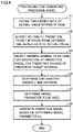
- Fig. 10 is a flowchart showing a more detailed processing procedure involved with selection of a training sample (step S3) in the processing procedure in generation processing shown in Fig. 4 .
- support apparatus 200 generates a sample by trimming time-series data of interest (step S31).
- the time-series data is trimmed by extracting only a part relating to the prediction target interval.
- support apparatus 200 calculates one or more feature values from each sample (step S32) and carries out clustering based on the one or more calculated feature values (step S33).
- Support apparatus 200 selects one or more samples from each of one or more classes determined by clustering and determines the selected sample(s) as the training sample(s) (step S34).
- Support apparatus 200 thus performs as the function involved with generation of prediction model 140, processing for selecting a sample to be used as the training sample from among a plurality of samples by clustering using one or more feature values calculated from each sample.
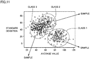
- Fig. 11 is a diagram showing exemplary clustering involved with selection of a training sample in the processing procedure in the generation processing shown in Fig. 4 .
- Fig. 11 shows an example in which two feature values (an average value and a standard deviation) are calculated from each sample and each sample is plotted in a two-dimensional space where each feature value is expressed in a coordinate.
- a sample group shown in Fig. 11 includes three clusters (classes 1 to 3) with attention being paid to the feature values which are the average value and the standard deviation.
- One or more samples belonging to each extracted class are selected. Specifically, one or more samples belonging to class 1 are extracted, one or more samples belonging to class 2 are extracted, and one or more samples belonging to class 3 are extracted. A plurality of samples different in class from one another are thus determined as the training samples.
- a sample of interest of the training sample may automatically be selected by support apparatus 200, or a user may support the processing or check a result of selection. For example, the user may check a result of selection of a sample and may manually make selection again.
- Fig. 12 is a diagram showing an exemplary user interface provided in processing for selecting a training sample in prediction system 1 according to the embodiment.
- Fig. 13 is a diagram showing another exemplary user interface provided in processing for selecting a training sample in prediction system 1 according to the embodiment.
- Figs. 12 and 13 each show exemplary representation of a result of selection of a sample.
- a user interface screen 250 shown in Fig. 12 can show a synthesized waveform 252 shown by superimposing checked samples in a selected sample group 254 on one another on an identical time axis.
- a user can readily check suitability of selection of a sample by selecting any samples from sample group 254 and showing them as synthesized waveform 252.
- a user interface screen 260 shown in Fig. 13 shows similarity among selected samples in a form of rows and columns.
- User interface screen 260 includes representation elements arranged in rows and columns, and waveforms of samples are arranged on a single diagonal.
- a similarity 264 (correlation coefficient) among samples is shown above the diagonal, and a synthesized waveform 262 shown by superimposing two corresponding samples on each other on the identical time axis is shown below the diagonal.
- the user interface screens shown in Figs. 12 and 13 may be shown on the same screen. In this case, when the user selects any sample in user interface screen 250, a corresponding sample in user interface screen 260 shown in Fig. 13 may be highlighted in correspondence with the selected sample. Furthermore, alternate switching between a selected object and a non-selected object may be made by selecting any waveform in user interface screen 250.
- a training sample to be used for generation of a prediction model is selected.
- step S4 shown in Fig. 4 support apparatus 200 determines an explanatory variable and an interval involved with prediction model 140.
- step S4 a prediction algorithm adopted for prediction model 140 is fixed to a default value or the like. Then, prediction model 140 is generated for each of combinations varied in explanatory variable and interval, and the explanatory variable and the interval to be used are determined by evaluating performance. In other words, support apparatus 200 fixes a model parameter for prediction model 140, and then searches for an explanatory variable and an interval to be used for prediction.
- a control cycle set in the user program executed in control device 100 may be referred to and a preferred search interval may be determined based on the set control cycle.
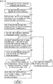
- Fig. 14 is a flowchart showing a more detailed processing procedure involved with determination of an explanatory variable and an interval (step S4) in the processing procedure in the generation processing shown in Fig. 4 .
- support apparatus 200 obtains the control cycle by referring to the user program executed in control device 100 of interest (step S41). While support apparatus 200 is connected to control device 100, necessary information may be obtained by accessing control device 100, and while support apparatus 200 is not connected to control device 100, the control cycle may be obtained by referring to a project or the like held in support apparatus 200.
- Support apparatus 200 sets an integral multiple of the obtained control cycle as the search interval for searching for the interval (step S42).
- Support apparatus 200 selects one or more explanatory variables from a plurality of variables associated with a training sample selected in advance (see step S3 described above) (step S43). More specifically, support apparatus 200 calculates importance of each variable by applying a decision tree algorithm to the training sample and the plurality of associated variables. Then, support apparatus 200 selects a variable high in importance as the explanatory variable.
- decision tree algorithm Any known algorithm can be adopted as the decision tree algorithm, and for example, random forest or the like may be employed.
- Support apparatus 200 thus performs as the function involved with generation of prediction model 140, processing for determining as the explanatory variable, one or more variables (status values) among a plurality of variables (status values) associated with the training sample to be used for generation of prediction model 140, based on the importance with respect to the training sample.
- Support apparatus 200 sets any one candidate interval included in the search interval (step S44).
- the candidate interval is generated by varying a length and/or a position of the interval included in the search interval.
- support apparatus 200 generates prediction model 140 with the use of the training sample, with one or more explanatory variables selected in step S43 and the candidate interval set in step S44 being defined as parameters (step S45).
- support apparatus 200 evaluates performance involved with inference of generated prediction model 140 (step S46). In step S46, a numerical value indicating performance is stored in association with the corresponding candidate interval.
- support apparatus 200 determines whether or not generation and evaluation of performance of prediction model 140 for all candidate intervals included in the search interval have been completed (step S47). When generation and evaluation of performance of prediction model 140 for all candidate intervals included in the search interval have not been completed (NO in step S47), support apparatus 200 sets another candidate interval included in the search interval (step S48) and repeats processing in step S45 or later.
- support apparatus 200 determines the candidate interval exhibiting highest evaluation of performance as the interval for prediction model 140 (step S49).
- Support apparatus 200 thus performs as the function involved with generation of prediction model 140, processing for determining an interval to be used for prediction by successively varying the interval included in the search interval and evaluating accuracy of prediction with the determined explanatory variable.
- processing for determining the interval to be used for prediction support apparatus 200 evaluates performance of the prediction models generated in patterns varied in at least one of the length and the position of the interval included in the search interval.
- Fig. 15 is a schematic diagram for outlining processing contents in determination of an explanatory variable and an interval (step S4) in the processing procedure in the generation processing shown in Fig. 4 .
- the explanatory variable is determined by applying the decision tree algorithm to a plurality of variables 1, 2, ..., and n.
- a training sample is used for application of the decision tree algorithm.
- the search interval is determined based on the user program, and one or more candidate intervals are set from the determined search interval.
- Prediction model 140 is then generated for each candidate interval, and performance of generated prediction model 140 is evaluated.
- step S4 shown in Fig. 4 support apparatus 200 determines the explanatory variable based on the importance calculated with the decision tree algorithm, and determines the explanatory variable and the interval by carrying out grid search (brute-force search) on the interval within the search interval with the use of the determined explanatory variable.
- grid search brute-force search
- step S43 In the processing procedure in the generation processing shown in Fig. 14 described above, some candidates may also be set for the explanatory variable, and processing in step S44 or later may be performed for each candidate (each candidate including one or more explanatory variables).
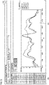
- Figs. 16 to 19 are each a diagram showing an exemplary user interface provided in processing for determining an explanatory variable and an interval in prediction system 1 according to the embodiment.
- a user interface screen 270 includes a waveform display area 276 where an actual value and a prediction value are shown.
- Waveforms (time-series data) of the actual value and the prediction value are shown in waveform display area 276.
- the actual value exhibits a waveform (time-series data) of any sample included in the training sample.
- the prediction value exhibits a waveform (time-series data) provided by generated prediction model 140.
- a position and a duration of an interval 272 that delimits a range of the explanatory variable entered in prediction model 140 can freely be set for a predetermined prediction point 271.
- the user can freely change an interval width 273 of interval 272 and a time difference 274 from the prediction point by operating a mouse or the like to move the position of interval 272.
- the waveform (time-series data) of the prediction value is calculated in accordance with interval 272 freely set by the user, and the calculated waveform (time-series data) of the prediction value is shown in waveform display area 276.
- User interface screen 270 includes an explanatory variable list 277, and a checked variable of one or more variables is used as the explanatory variable.
- User interface screen 270 includes a prediction error 275 indicating deviation between the actual value and the prediction value.
- support apparatus 200 may use prediction model 140 generated in the processing shown in Fig. 14 as it is to calculate the prediction value.
- support apparatus 200 may perform again the processing in step S43 or later or processing in step S44 or later in Fig. 15 in response to change as appropriate of the explanatory variable and/or the interval by the operation onto user interface screen 270 by the user.
- prediction model 140 may be generated again.
- the user can determine the explanatory variable and/or the interval while the user searches for the explanatory variable and/or the interval to be set in prediction model 140.
- Support apparatus 200 thus provides user interface screen 270 (see Figs. 16 to 19 ) where the operation by the user for changing the interval to be used for prediction is accepted.
- the explanatory variable and the interval to be used for the prediction model are determined.
- step S5 shown in Fig. 4 support apparatus 200 determines the model parameter to be used for prediction model 140.
- step S4 the explanatory variable and the interval are determined, with the prediction algorithm or the like adopted for prediction model 140 being fixed to the default value or the like.
- step S5 based on the determined explanatory variable and interval as the premise, the model parameter of prediction model 140 is determined in consideration of operational indicators such as prediction accuracy, a model size, a processing speed, and the like.
- the plurality of indicators preferably include at least one of prediction accuracy, the model size, and the processing speed.
- Fig. 20 is a flowchart showing a more detailed processing procedure involved with determination of a model parameter (step S5) shown in Fig. 4 .
- support apparatus 200 determines a range of search for a model parameter (step S51).
- the range of search for the model parameter delimits a range of search (upper and lower limits) for each parameter in addition to the type of the parameter to be searched for.
- support apparatus 200 selects as a target, a data set of any model parameter included within the range of search determined in step S51 (step S52). Then, support apparatus 200 generates prediction model 140 based on the selected data set of the model parameter (step S53) and evaluates performance (prediction accuracy, the model size, the processing speed, and the like) of generated prediction model 140 (step S54).
- Support apparatus 200 determines whether or not there is another data set of a model parameter included in the range of search determined in step S51 (step S55). When there is another data set of the model parameter included in the range of search determined in step S51 (YES in step S55), support apparatus 200 selects another data set of the model parameter included in the range of search determined in step S51 (step S56) and repeats processing in step S53 or later.
- support apparatus 200 searches for a most appropriate data set of a model parameter based on a result of evaluation of performance for each data set (step S57) and shows a found model parameter and a corresponding result of evaluation of performance (step S58).
- support apparatus 200 determines a model parameter for generating prediction model 140 in accordance with an instruction from a user (step S59).
- Support apparatus 200 thus performs as the function involved with generation of prediction model 140, processing for determining the model parameter for defining prediction model 140 by evaluating a plurality of indicators for prediction model 140 defined by each model parameter, with the model parameter defining prediction model 140 being successively varied, under a condition of the determined explanatory variable and the determined interval.
- Fig. 21 is a diagram showing an exemplary user interface provided in processing for determining a model parameter in prediction system 1 according to the embodiment.
- user interface screen 270 shown in Fig. 21 prediction accuracy 281, a model size 282, and a processing speed 283 that have been calculated are additionally shown, as compared with user interface screen 270 shown in Figs. 16 to 19 .
- Support apparatus 200 thus provides user interface screen 270 showing a plurality of indicators (see Fig. 21 ). The user can also adjust the explanatory variable and the interval while the user checks these indicators.
- An optimal model parameter may be searched for in step S57 in Fig. 20 by setting a priority for such indicators as prediction accuracy, the model size, and the processing speed.
- the priority for the indicators is set in the order of prediction accuracy, the model size, and the processing speed.
- a minimum condition may be set for each indicator.
- support apparatus 200 extracts a set of good model parameters for the indicator with priority 1, and then searches for a data set good in both of the indicator with priority 2 and the indicator with priority 3.
- Any priority may be set for any indicator, and the same priority may be set for a plurality of indicators. Furthermore, without setting the priority, results of evaluation of indicators may be generalized to determine an optimal data set.
- a model parameter generally good in indicator (typically, high in accuracy, small in model size, and high in processing speed) can be determined by grid search (brute-force search).
- the user can generate appropriate prediction model 140 by finely adjusting the model parameter, the explanatory variable, the interval, and the like as necessary while the user checks performance of the prediction model based on the determined model parameter on the user interface screen.
- prediction model 140 can be determined by comprehensive evaluation inclusive of a plurality of indicators such as prediction accuracy, the model size, the processing speed, and the like.
- prediction system 1 that predicts change over time is described in the description above, the prediction system is applicable also to an abnormality sensing system that senses an abnormality that occurs in an object to be controlled or the like.
- Fig. 22 is a schematic diagram showing an overall configuration of an abnormality sensing system 1A according to a modification of the present embodiment.
- abnormality sensing system 1A selects a training sample from raw data 40 obtained from an object to be controlled (sample selection 42), and generates an abnormality sensing model 44 based on the selected training sample. Then, operation 46 of abnormality sensing is performed using generated abnormality sensing model 44.
- Abnormality sensing model 44 aims to sense that the object to be controlled exhibits a state different from a normal state. With the use of raw data (time-series data) collected from the object to be controlled, abnormality sensing model 44 adapted to collected raw data is generated. Input of raw data different from an input in the normal state to abnormality sensing model 44 leads to output of a value indicating that a state is different from the normal state, so that occurrence of some kind of abnormality in the object to be controlled can be sensed.
- raw data different in pattern of variation is preferably adopted.
- Fig. 23 is a diagram for illustrating exemplary processing for sample selection shown in Fig. 22 .
- raw data 401 and raw data 404 are similar in distribution.
- raw data 402 and raw data 405 are similar in distribution.
- step S3 By thus extracting samples different in pattern of variation from one another as in step S3 described above also for the training sample to be used for abnormality sensing model 44, sensing performance of abnormality sensing model 44 can be enhanced.
- a prediction system comprising:
- prediction model generator further comprises means (2261) configured to select a sample to be used as the training sample from among a plurality of samples by clustering using one or more feature values calculated from each sample.
- prediction model generator is configured to evaluate performance of prediction models generated in patterns different in at least one of a length and a position of an interval included in the search interval.
- prediction model generator is configured to fix a model parameter of the prediction model and then search for an interval to be used for the prediction.
- prediction model generator further comprises means configured to provide a first user interface (270) that accepts an operation by a user for changing an interval to be used for the prediction.
- prediction model generator further comprises means configured to provide a second user interface (270) that shows the plurality of indicators.
- An information processing apparatus connected to a control device (100), the control device comprising a control operation unit (164) configured to perform operation for controlling an object to be controlled and a prediction value obtaining unit (156) configured to obtain a prediction value by entering an actual value composed of one or more status values among status values that can be referred to by the control operation unit into a prediction model, the information processing apparatus comprising, as a prediction model generator configured to determine the prediction model in advance:
- the prediction model can finally be determined based on a plurality of indicators, and hence a prediction model suitable for actual operation can readily be generated.
Landscapes
- Engineering & Computer Science (AREA)
- Physics & Mathematics (AREA)
- General Physics & Mathematics (AREA)
- Automation & Control Theory (AREA)
- Business, Economics & Management (AREA)
- Theoretical Computer Science (AREA)
- Evolutionary Computation (AREA)
- Artificial Intelligence (AREA)
- Economics (AREA)
- Human Resources & Organizations (AREA)
- Strategic Management (AREA)
- General Engineering & Computer Science (AREA)
- Health & Medical Sciences (AREA)
- Software Systems (AREA)
- Quality & Reliability (AREA)
- Mathematical Physics (AREA)
- General Health & Medical Sciences (AREA)
- Molecular Biology (AREA)
- Marketing (AREA)
- Biomedical Technology (AREA)
- Biophysics (AREA)
- Computational Linguistics (AREA)
- Data Mining & Analysis (AREA)
- Entrepreneurship & Innovation (AREA)
- Tourism & Hospitality (AREA)
- Life Sciences & Earth Sciences (AREA)
- Computing Systems (AREA)
- Game Theory and Decision Science (AREA)
- Operations Research (AREA)
- General Business, Economics & Management (AREA)
- Development Economics (AREA)
- Manufacturing & Machinery (AREA)
- Computer Vision & Pattern Recognition (AREA)
- Medical Informatics (AREA)
- Management, Administration, Business Operations System, And Electronic Commerce (AREA)
- Testing And Monitoring For Control Systems (AREA)
Abstract
Description
- The present invention relates to a prediction system that predicts change that occurs in an object to be controlled, an information processing apparatus included in the prediction system, and an information processing program for implementing the information processing apparatus.
- At various production sites, for some reasons, change different from natural change or change different from normal change may occur. If occurrence of such change could be predicted in advance and some measures could be taken, it would be beneficial for maintaining performance of a production facility or ensuring quality of products.
- In connection with prediction in advance as such, for example,
Japanese Patent Laying-Open No. 2009-237832 PTL 1 adopts processing for selecting an optimal training period and an optimal prediction model highest in prediction accuracy by constructing a prediction model appropriate for each of a plurality of training periods ranging from seven to seventy days using training data obtained by correcting accumulated time-series data and evaluating accuracy of modeling for each training period. - PTL 1:
Japanese Patent Laying-Open No. 2009-237832 - In the method of constructing the variable prediction model disclosed in
PTL 1 described above, however, a prediction model appropriate for each of the plurality of training periods should be constructed and then accuracy in modeling for each training period should be evaluated. The method is disadvantageous in large number of man-hours required for selection of an optimal training period and an optimal prediction model. - The present invention provides an approach to more efficient generation of a prediction model.
- A prediction system according to one example of the present invention includes a control operation unit that performs operation for controlling an object to be controlled, a prediction value obtaining unit that obtains a prediction value by entering an actual value composed of one or more status values among status values that can be referred to by the control operation unit into a prediction model, and a prediction model generator that determines the prediction model in advance. The prediction model generator includes means that determines as an explanatory variable, one or more status values among a plurality of status values associated with a training sample to be used for generation of the prediction model, based on importance with respect to the training sample, means that determines an interval to be used for prediction by evaluating accuracy of prediction with the determined explanatory variable, with an interval included in a search interval being successively varied, and means that determines a model parameter for defining the prediction model by evaluating a plurality of indicators for the prediction model defined by each model parameter, with the model parameter defining the prediction model being successively varied, under a condition of the determined explanatory variable and the determined interval.
- According to this configuration, the prediction model for which the plurality of indicators have been evaluated can readily been generated.
- The prediction model generator may further include means that selects a sample to be used as the training sample from among a plurality of samples by clustering using one or more feature values calculated from each sample. According to this configuration, a large number of samples similar to one another can be prevented from being selected as training samples.
- The prediction model generator may calculate importance of each status value by applying a decision tree algorithm to the training sample and a plurality of associated status values. According to this configuration, by applying the decision tree algorithm, which status value is suitable for the prediction model can readily be determined.
- The prediction model generator may evaluate performance of prediction models generated in patterns different in at least one of a length and a position of an interval included in the search interval. According to this configuration, a suitable interval included in the search interval can readily be found.
- The prediction model generator may fix a model parameter of the prediction model and then search for an interval to be used for prediction. According to this configuration, by once fixing the model parameter of the prediction model, throughput involved with search can be reduced.
- The prediction model generator may further include means that provides a first user interface that accepts an operation by a user for changing an interval to be used for prediction. According to this configuration, the user can finely adjust the determined interval while checking.
- The plurality of indicators may include at least one of prediction accuracy, a model size, and a processing speed. According to this configuration, an element on which importance is to be placed during operation is included in the indicator, so that the optimal prediction model can be generated in consideration of operation.
- The prediction model generator may further include means that provides a second user interface that shows the plurality of indicators. According to this configuration, a user can know the plurality of determined indicators at a glance.
- According to another example of the present invention, an information processing apparatus connected to a control device is provided. The control device includes a control operation unit that performs operation for controlling an object to be controlled and a prediction value obtaining unit that obtains a prediction value by entering an actual value composed of one or more status values among status values that can be referred to by the control operation unit into a prediction model. The information processing apparatus includes, as a prediction model generator that determines the prediction model in advance, means that determines as an explanatory variable, one or more status values among a plurality of status values associated with a training sample to be used for generation of the prediction model, based on importance with respect to the training sample, means that determines an interval to be used for prediction by evaluating accuracy of prediction with the determined explanatory variable, with an interval included in a search interval being successively varied, and means that determines a model parameter for defining the prediction model by evaluating a plurality of indicators for the prediction model defined by each model parameter, with the model parameter defining the prediction model being successively varied, under a condition of the determined explanatory variable and the determined interval.
- According to yet another example of the present invention, an information processing program executed by a computer connected to a control device is provided. The control device includes a control operation unit that performs operation for controlling an object to be controlled and a prediction value obtaining unit that obtains a prediction value by entering an actual value composed of one or more status values among status values that can be referred to by the control operation unit into a prediction model. The information processing program causes the computer to perform, as processing for determining the prediction model in advance, determining as an explanatory variable, one or more status values among a plurality of status values associated with a training sample to be used for generation of the prediction model, based on importance with respect to the training sample, determining an interval to be used for prediction by evaluating accuracy of prediction with the determined explanatory variable, with an interval included in a search interval being successively varied, and determining a model parameter for defining the prediction model by evaluating a plurality of indicators for the prediction model defined by each model parameter, with the model parameter defining the prediction model being successively varied, under a condition of the determined explanatory variable and the determined interval.
- According to the present invention, a prediction model can more efficiently be generated.
-
-
Fig. 1 is a schematic diagram showing an exemplary overall configuration of a prediction system according to the present embodiment. -
Fig. 2 is a schematic diagram showing an exemplary application of the prediction system according to the present embodiment. -
Fig. 3 is a schematic diagram showing exemplary control based on a result of prediction by the prediction system according to the present embodiment. -
Fig. 4 is a flowchart showing a processing procedure in processing for generating a prediction model with the use of the prediction system according to the present embodiment. -
Fig. 5 is a block diagram showing an exemplary hardware configuration of a control device included in the prediction system according to the present embodiment. -
Fig. 6 is a block diagram showing an exemplary hardware configuration of a support apparatus included in the prediction system according to the present embodiment. -
Fig. 7 is a block diagram showing an exemplary software configuration of the control device and the support apparatus included in the prediction system according to the present embodiment. -
Fig. 8 is a block diagram showing overview of a functional module included in an analysis program shown inFig. 7 . -
Fig. 9 is a diagram for illustrating exemplary selection of a training sample in the prediction system according to the present embodiment. -
Fig. 10 is a flowchart showing a more detailed processing procedure involved with selection of a training sample (step S3) in the processing procedure in generation processing shown inFig. 4 . -
Fig. 11 is a diagram showing exemplary clustering involved with selection of a training sample in the processing procedure in the generation processing shown inFig. 4 . -
Fig. 12 is a diagram showing an exemplary user interface provided in processing for selecting a training sample in the prediction system according to the embodiment. -
Fig. 13 is a diagram showing another exemplary user interface provided in processing for selecting a training sample in the prediction system according to the embodiment. -
Fig. 14 is a flowchart showing a more detailed processing procedure involved with determination of an explanatory variable and an interval (step S4) in the processing procedure in the generation processing shown inFig. 4 . -
Fig. 15 is a schematic diagram for outlining processing contents in determination of an explanatory variable and an interval (step S4) in the processing procedure in the generation processing shown inFig. 4 . -
Fig. 16 is a diagram showing an exemplary user interface provided in processing for determining an explanatory variable and an interval in the prediction system according to the embodiment. -
Fig. 17 is a diagram showing an exemplary user interface provided in processing for determining an explanatory variable and an interval in the prediction system according to the embodiment. -
Fig. 18 is a diagram showing an exemplary user interface provided in processing for determining an explanatory variable and an interval in the prediction system according to the embodiment. -
Fig. 19 is a diagram showing an exemplary user interface provided in processing for determining an explanatory variable and an interval in the prediction system according to the embodiment. -
Fig. 20 is a flowchart showing a more detailed processing procedure involved with determination of a model parameter (step S5) shown inFig. 4 . -
Fig. 21 is a diagram showing an exemplary user interface provided in processing for determining a model parameter in aprediction system 1 according to the embodiment. -
Fig. 22 is a schematic diagram showing an overall configuration of an abnormality sensing system according to a modification of the present embodiment. -
Fig. 23 is a diagram for illustrating exemplary processing for sample selection shown inFig. 22 . - An embodiment of the present invention will be described in detail with reference to the drawings. The same or corresponding elements in the drawings have the same reference characters allotted and description thereof will not be repeated.
- An exemplary scene to which the present invention is applied will initially be described.
- A primary aspect of a control system with a prediction function according to the present embodiment will be described. Since description is given below with a prediction function of the control system being mainly focused on, the entire control system is also referred to as a "prediction system."
-
Fig. 1 is a schematic diagram showing an exemplary overall configuration of aprediction system 1 according to the present embodiment. Referring toFig. 1 ,prediction system 1 according to the present embodiment includes, as its main constituent elements, acontrol device 100 that controls an object to be controlled and asupport apparatus 200 connected to controldevice 100. -
Control device 100 may be implemented by a kind of a computer such as a programmable controller (PLC).Control device 100 is connected to afield apparatus group 10 over afield bus 2 and connected to one ormore display apparatuses 400 over afield bus 4.Control device 100 may further be connected to a higher-order server 300 over a higher-order network 6. Higher-order server 300 anddisplay apparatus 400 are optional features and they are not features essential forprediction system 1. -
Control device 100 includes a control logic (which is also referred to as a "PLC engine" below) that performs various types of operations for controlling facilities or machines. In addition to the PLC engine,control device 100 performs a collection function to collect data (which is also referred to as "input data" below) measured infield apparatus group 10 and transferred to controldevice 100. Furthermore,control device 100 also performs a prediction function to predict change over time in the future based on collected input data. - Specifically, a time-series database (which is also denoted as "TSDB" below) 130 implemented in
control device 100 provides a collection function, and aprediction model 140 implemented incontrol device 100 provides a monitoring function. Details ofTSDB 130 andprediction model 140 will be described later. - Preferably, an industrial communication protocol is adopted for
field bus 2 andfield bus 4. EtherCAT®, EtherNet/IP™, DeviceNet™, and CompoNet™ have been known as such a communication protocol. -
Field apparatus group 10 includes an apparatus that collects input data from an object to be controlled or a manufacturing apparatus or a production line (which will also collectively be referred to as a "field" below) relating to control. An input relay and various sensors are assumed as such an apparatus that collects input data.Field apparatus group 10 further includes an apparatus that performs some actions onto a field based on an instruction (which is also referred to as "output data" below) generated bycontrol device 100. An output relay, a contactor, a servo driver and a servo motor, and any other actuators are assumed as an apparatus that performs some actions onto such a field.Field apparatus group 10 exchanges data including input data and output data withcontrol device 100 overfield bus 2. - In an exemplary configuration shown in
Fig. 1 ,field apparatus group 10 includes a remote input/output (I/O)apparatus 12, arelay group 14, animage sensor 18 and acamera 20, and aservo driver 22 and aservo motor 24. - Remote I/
O apparatus 12 includes a communication unit that establishes communication overfield bus 2 and an input and output unit (which is also referred to as an "I/O unit" below) for collecting input data and providing output data. Input data and output data are exchanged betweencontrol device 100 and the field with such an I/O unit being interposed.Fig. 1 shows an example in which a digital signal is exchanged as input data and output data withrelay group 14 being interposed. - The I/O unit may directly be connected to the field bus.
Fig. 1 shows an example in which an I/O unit 16 is directly connected to fieldbus 2. -
Image sensor 18 performs image measurement processing such as pattern matching onto data of images picked up bycamera 20 and transmits a result of processing to controldevice 100. -
Servo driver 22drives servo motor 24 in accordance with output data (for example, a position instruction) fromcontrol device 100. - As described above, data is exchanged between
control device 100 andfield apparatus group 10 overfield bus 2. Such exchanged data is updated in very short cycles of the order of several hundred microseconds to several ten milliseconds. Processing for updating such exchanged data may also be referred to as "I/O refresh processing." - Upon receiving an operation from a user,
display apparatus 400 connected to controldevice 100 overfield bus 4 transmits a command in accordance with the operation by the user to controldevice 100 and graphically shows a result of operation incontrol device 100. - Higher-
order server 300 is connected to controldevice 100 over higher-order network 6 and exchanges necessary data withcontrol device 100. A general-purpose protocol such as Ethernet™ is implemented in higher-order network 6. -
Support apparatus 200 is an information processing apparatus (an exemplary computer) that supports preparation necessary forcontrol device 100 to control an object to be controlled. Specifically,support apparatus 200 provides an environment (a program creation and edition tool, a parser, or a compiler) for developing a user program to be executed incontrol device 100, a setting environment for setting a parameter (configuration) forcontrol device 100 and various devices connected to controldevice 100, a function to transmit a generated user program to controldevice 100, and a function to modify and change on-line, the user program executed oncontrol device 100. - Furthermore,
support apparatus 200 according to the present embodiment performs a function to support generation and optimization ofprediction model 140 implemented incontrol device 100. In other words,support apparatus 200 includes a prediction model generator that determinesprediction model 140 in advance. Details of such a function will be described later. - An exemplary application of
control device 100 included inprediction system 1 will now be described. -
Fig. 2 is a schematic diagram showing an exemplary application ofprediction system 1 according to the present embodiment.Fig. 2 shows an exemplary production facility including apressing machine 30. - Referring to
Fig. 2 , pressingmachine 30 accepts aworkpiece 31 and arranges acceptedworkpiece 31 on asupport base 34 provided on abase 33. Then, workpiece 31 is compressed by apressing plate 35 provided at a tip end of adriveshaft 36 driven by amotor 37 to produce anintermediate product 32. - It is assumed that a defect can occur in
intermediate product 32 due to unexpected factor fluctuation in pressingmachine 30. Therefore, whether or not a defect has occurred inintermediate product 32 is determined by inspection with an inspection instrument arranged downstream from pressingmachine 30 or visual inspection by an inspector or inspection by sampling. When it is determined that the defect has occurred, a target value or the like is adjusted each time. - Thus, in a normal manufacturing process, in order to maintain or improve a ratio of non-defective
intermediate products 32, the target value should be adjusted each time. It is difficult, however, to address all factor fluctuations in spite of design in advance from various points of view. - In contrast, by predicting a state of intermediate product 32 (that is, quality after working) based on
prediction model 140 according to the present embodiment, control bycontrol device 100 can be corrected before the defect actually occurs. By making use of such prediction of occurrence of a defect in advance, the number of man-hours involved with adjustment of the target value or the like each time can be reduced, and occurrence of a defect inintermediate product 32 can be prevented. -
Fig. 3 is a schematic diagram showing exemplary control based on a result of prediction byprediction system 1 according to the present embodiment. -
Fig. 3 (A) shows a planned value (an instruction) of a position of pressing by the pressing machine at a certain time point and an actual position (an actual value) of pressing by pressingmachine 30. The target value represents an intended thickness of workedintermediate product 32. - Referring to
Fig. 3 (B) , at a certain time point, a future position (a prediction value) of pressing by pressingmachine 30 may be calculated based on information until that time point (which may include the actual value), and an amount of control for pressingmachine 30 may be corrected based on the calculated prediction value. - In pressing
machine 30 shown inFigs. 2 and3 , by predicting the position of pressing by pressingmachine 30 and correcting the amount of control based on the result of prediction, an operator does not have to adjust the target value each time, for example, depending on variation in hardness ofworkpiece 31. Consequently, production of a defective product due to unexpected factor fluctuation can be suppressed and quality can be stabilized in spite of some variation inworkpiece 31. - Data (an actual value or an observation value) to be used for prediction and predicted data may be identical to each other in part or in the entirety, or may completely be different from each other.
-
Prediction system 1 according to the present embodiment provides a function to appropriately generateprediction model 140. The function to appropriately generateprediction model 140 may typically be implemented insupport apparatus 200. - Overview of generation and operation of
prediction model 140 with the use ofprediction system 1 according to the present embodiment will now be described. -
Fig. 4 is a flowchart showing a processing procedure in processing for generatingprediction model 140 with the use ofprediction system 1 according to the present embodiment. Each step shown inFig. 4 is typically performed by execution of a program (ananalysis program 226, anOS 228, and the like) by aprocessor 202 ofsupport apparatus 200. - Referring to
Fig. 4 ,support apparatus 200 obtains time-series data of an actual value stored in TSDB 130 (step S1). In succession,support apparatus 200 accepts setting of a prediction target interval from the obtained time-series data of the actual value (step S2). -
Support apparatus 200 selects a training sample to be used for generation of a prediction model for predicting change of the prediction target interval set in step S2 (step S3). In step S3, which data among a plurality of types of data is to be used for training is selected. More specifically,support apparatus 200 determines a class by clustering of a statistic (a feature value) of each piece of time-series data (waveform sample) and extracts data of interest from the determined class. Processing in step S3 will be described in detail. - In succession,
support apparatus 200 determines an explanatory variable and an interval (step S4). Then,support apparatus 200 determines a model parameter to be used (step S5). In step S5,support apparatus 200 generatesprediction model 140 in accordance with the explanatory variable and the interval selected in step S4 and searches for an appropriate prediction algorithm by evaluating performance of generatedprediction model 140.Support apparatus 200 determines the prediction algorithm high in performance such as prediction accuracy and a prediction speed as the model parameter to be used. - Finally,
support apparatus 200 generatesprediction model 140 based on the determined model parameter and the like (step S6). -
Prediction model 140 generated through the processing procedure as above is set incontrol device 100, so that operations as shown inFigs. 2 and3 can be performed. - An exemplary hardware configuration of a main apparatus included in
prediction system 1 according to the present embodiment will now be described. -
Fig. 5 is a block diagram showing an exemplary hardware configuration ofcontrol device 100 included inprediction system 1 according to the present embodiment. Referring toFig. 5 ,control device 100 includes aprocessor 102 such as a central processing unit (CPU) or a micro-processing unit (MPU), achip set 104, amain storage 106, asecondary storage 108, a higher-order network controller 110, a universal serial bus (USB)controller 112, amemory card interface 114, aninternal bus controller 122,field bus controllers -
Processor 102 reads various programs stored insecondary storage 108, develops the programs onmain storage 106, and executes the programs, to thereby implement a PLC engine 150 (seeFig. 7 ) andprediction model 140. Chip set 104 controls data transmission or the like betweenprocessor 102 and each component. - In addition to a system program for implementing
PLC engine 150, a user program executed by usingPLC engine 150 is stored insecondary storage 108. A program for implementingprediction model 140 is further also stored insecondary storage 108. - Higher-
order network controller 110 controls exchange of data with another apparatus over higher-order network 6.USB controller 112 controls exchange of data withsupport apparatus 200 through USB connection. -
Memory card interface 114 is constructed such that amemory card 116 can be attached thereto and detached therefrom, and allows writing of data intomemory card 116 and reading of various types of data (the user program or trace data) frommemory card 116. -
Internal bus controller 122 is an interface for exchange of data with I/O units 124-1, 124-2, ... mounted oncontrol device 100. -
Field bus controller 118 controls exchange of data with another apparatus overfield bus 2. Similarly,field bus controller 120 controls exchange of data with another apparatus overfield bus 4. - Though
Fig. 5 shows an exemplary configuration in which a necessary function is provided by execution of a program byprocessor 102, a part or the entirety of these provided functions may be performed by using dedicated hardware circuitry (for example, an application specific integrated circuit (ASIC) or a field-programmable gate array (FPGA)). Alternatively, a principal part ofcontrol device 100 may be implemented by hardware (for example, an industrial personal computer based on a general-purpose personal computer) in accordance with a general-purpose architecture. In this case, using virtualization technology, a plurality of operating systems (OSs) different in application are executed in parallel and a necessary application may be executed on each OS. -
Support apparatus 200 according to the present embodiment is implemented by execution of a program with the use of hardware (for example, a general-purpose personal computer) in accordance with a general-purpose architecture by way of example. -
Fig. 6 is a block diagram showing an exemplary hardware configuration ofsupport apparatus 200 included inprediction system 1 according to the present embodiment. Referring toFig. 6 ,support apparatus 200 includesprocessor 202 such as a CPU or an MPU, anoptical drive 204, amain storage 206, asecondary storage 208, aUSB controller 212, a higher-order network controller 214, aninput device 216, and adisplay device 218. These components are connected to one another through abus 220. -
Processor 202 performs various types of processing including model generation processing as will be described later by reading various programs stored insecondary storage 208, developing the programs onmain storage 206, and executing the programs. -
Secondary storage 208 is implemented, for example, by a hard disk drive (HDD) or a flash solid state drive (SSD). Insecondary storage 208, typically, adevelopment program 222 for creation of a user program to be executed insupport apparatus 200, debugging of the created user program, definition of a system configuration, and setting of various parameters, aPLC interface program 224 for exchange of data on the prediction function withcontrol device 100, ananalysis program 226 for implementing generation or the like ofprediction model 140, andOS 228 are stored. A necessary program other than the program shown inFig. 6 may be stored insecondary storage 208. -
Support apparatus 200 includesoptical drive 204. A program stored in arecording medium 205 in which a computer readable program is stored in a non-transitory manner (for example, an optical recording medium such as a digital versatile disc (DVD)) is read from the recording medium and installed insecondary storage 208 or the like. - Though various programs to be executed in
support apparatus 200 may be installed from computerreadable recording medium 205, it may be installed as being downloaded from any server over a network. A function provided bysupport apparatus 200 according to the present embodiment may be performed by using a part of a module provided by the OS. -
USB controller 212 controls exchange of data withcontrol device 100 through USB connection. Higher-order network controller 214 controls exchange of data with another apparatus over any network. -
Input device 216 is constituted of a keyboard, a mouse, and the like, and accepts an operation by a user.Display device 218 is constituted of a display, various indicators, a printer, and the like, and provides output of a result of processing fromprocessor 202. - Though
Fig. 6 shows an exemplary configuration in which a necessary function is provided by execution of a program byprocessor 202, a part or the entirety of these provided functions may be performed by using dedicated hardware circuitry (for example, an ASIC or an FPGA). - An exemplary software configuration and an exemplary functional configuration of
control device 100 andsupport apparatus 200 included inprediction system 1 according to the present embodiment will now be described. -
Fig. 7 is a block diagram showing an exemplary software configuration ofcontrol device 100 andsupport apparatus 200 included inprediction system 1 according to the present embodiment. - Referring to
Fig. 7 ,control device 100 includes as its principal functional configuration,TSDB 130 andprediction model 140 in addition toPLC engine 150. -
PLC engine 150 sequentially interprets auser program 154 and performs designated control operation.PLC engine 150 manages a status value collected from the field in a form of a variable 152, and variable 152 is updated in predetermined cycles.PLC engine 150 may be implemented by execution of a system program byprocessor 102 ofcontrol device 100. - The "status value" herein encompasses an input value collected from the field, an instruction value provided to the field, and a system status value or an internal value managed within
control device 100. Since the "status value" is referred to in the form of the "variable" incontrol device 100 according to the present embodiment, the term "variable" is used in a sense encompassing the "status value" for the sake of convenience in the description below. The technical scope of the present invention, however, is not limited to the configuration in which the "status value" is referred to in the form of the "variable". -
User program 154 includes a predictionvalue obtaining code 156, anerror evaluation code 158, anadditional training code 160, aTSDB writing code 162, and acontrol operation code 164. - Prediction
value obtaining code 156 implements a prediction value obtaining unit that obtains a prediction value by entering an actual value composed of one or more status values among status values that can be referred to bycontrol operation code 164 intoprediction model 140. More specifically, predictionvalue obtaining code 156 includes an instruction to obtain a prediction value by obtaining a necessary actual value managed asvariable 152 and entering the actual value intoprediction model 140. -
Error evaluation code 158 includes an instruction to evaluate an error between the prediction value obtained by predictionvalue obtaining code 156 and a target value. -
Additional training code 160 includes an instruction to additionally trainprediction model 140 as necessary in accordance with the error evaluated byerror evaluation code 158.Additional training code 160 updates amodel parameter 142 that definesprediction model 140. -
TSDB writing code 162 obtains a predetermined variable among variables managed asvariables 152 and writes the variable into astorage area 132 inTSDB 130. -
Control operation code 164 implements the control operation unit that performs operation for controlling an object to be controlled. More specifically,control operation code 164 performs operation for controlling the object to be controlled and corrects the target value to be used for operation as necessary in accordance with the error evaluated byerror evaluation code 158. -
TSDB 130 includes anexport module 134 that exports data written instorage area 132 to supportapparatus 200 or the like as necessary. -
Prediction model 140 includes areference trajectory 144 in addition tomodel parameter 142 that definesprediction model 140. -
Development program 222 andanalysis program 226 are installed insupport apparatus 200. -
Development program 222 generatesuser program 154 in accordance with an operation by a user and transfers the user program to controldevice 100.Development program 222 performs also a function to modify as appropriate contents incontrol operation code 164. -
Analysis program 226 corresponds to an information processing program for implementing the prediction model generator that determinesprediction model 140 in advance. More specifically,analysis program 226 supports generation ofprediction model 140 and includes an explanatory variable andinterval determination module 2261, amodel generation module 2262, aninference module 2263, and anevaluation module 2264. - Explanatory variable and
interval determination module 2261 performs a function necessary for processing for determining an explanatory variable and an interval (see step S4 shown inFig. 4 ). -
Model generation module 2262 performs a function necessary for processing for generating prediction model 140 (see step S6 shown inFig. 4 ). -
Inference module 2263 makes an inference (prediction) with the use of generatedprediction model 140 and provides a result of prediction toevaluation module 2264.Evaluation module 2264 evaluates performance ofprediction model 140 of interest based on the result of prediction frominference module 2263. With the functions provided byinference module 2263 andevaluation module 2264, processing for determining a model parameter to be used (see step S5 shown inFig. 4 ) is performed. -
Fig. 8 is a block diagram showing overview of a functional module included inanalysis program 226 shown inFig. 7 . Referring toFig. 8 ,analysis program 226 ofsupport apparatus 200 includes as its principal functional configuration, auser interface 230, an input andoutput management module 236, ascreen display module 238, agraph library 240, ananalysis module 242, and ananalysis library 244. -
User interface 230 accepts setting from a user and performs comprehensive processing for providing various types of information to the user. A specific form of implementation is such thatuser interface 230 includes ascript engine 232 and performs set processing by reading asetting file 234 including scripts describing necessary processing. - Input and
output management module 236 includes a file input function to read data from a designated file or the like, a stream input function to receive a data stream, and a file output function to provide output of a file including generated data or the like. -
Screen display module 238 includes a line graph generation function to generate a line graph based on input data or the like and a parameter adjustment function to change various parameters upon receiving an operation by a user. With change of a parameter, the line graph generation function may update the line. The line graph generation function and the parameter adjustment function perform necessary processing by referring tograph library 240. -
Analysis module 242 is a module that performs principal processing ofanalysis program 226, and includes a waveform sampling function, an explanatory variable and interval selection function, a parameter selection function, and a model generation function. Each function included inanalysis module 242 is performed by referring toanalysis library 244. -
Analysis library 244 includes a library for each function included inanalysis module 242 to perform processing. More specifically,analysis library 244 may perform a statistic function, a decision tree function, a time-series regression function, a grid search function, a clustering function, an inference speed evaluation function, an accuracy evaluation function, and an abnormality sensing function. - Principal processing for generating
prediction model 140 shown inFig. 4 will be described below. - In step S1 shown in
Fig. 4 ,support apparatus 200 obtains time-series data of an actual value stored inTSDB 130 ofcontrol device 100 in accordance with an operation by a user. The user sets a prediction target interval while the user looks at the time-series data of the actual value shown onsupport apparatus 200. - The prediction target interval may be set as appropriate in accordance with characteristics of an object to be controlled as shown in
Figs. 2 and3 described above. - In step S3 shown in
Fig. 4 ,support apparatus 200 selects a training sample to be used for generation ofprediction model 140. - The "sample" herein means a data string having a prescribed time length and to be used as training data for a prediction value to be provided from
prediction model 140. Basically, time-series data (raw data) of a prediction target is used as the "sample". When the prediction target is a feature value extracted from time-series data, however, the feature value may be employed. The term "sample" is used with attention being paid to a unit of processing in processing a plurality of pieces of data, and contents of data included therein are not particularly limited. - Data referred to for calculating or determining any prediction value is herein also referred to as an "explanatory variable." Any prediction value is calculated or determined with the use of one or more "explanatory variables." Therefore, a training sample is associated with data that may be a candidate for the "explanatory variable" with some method.
- The "feature value" herein is a term that encompasses information included in time-series data to be processed, and it may include, for example, a maximum value, a minimum value, a median value, an average value, a standard deviation, a variance, and the like of time-series data of interest. The "feature value" may encompass also time-series data of interest itself.
-
Fig. 9 is a diagram for illustrating exemplary selection of a training sample inprediction system 1 according to the present embodiment.Fig. 9 shows exemplary time-series data (sample) having a prescribed time length in correspondence with a prediction target interval. - Among these samples, as samples various in pattern of variation are used more for training, prediction accuracy of
prediction model 140 can be higher. In other words, training with samples exhibiting similar patterns of variation does not contribute to improvement in prediction accuracy ofprediction model 140. - In the example shown in
Fig. 9 , four samples surrounded with a bold frame are selected as training samples different in pattern of variation from one another. - In an exemplary method of selecting samples different in pattern of variation from one another, one or more feature values (for example, an average value and/or a standard deviation) are calculated from each sample and samples are subjected to clustering based on the calculated one or more feature values. By such clustering, one or more classes included in a sample group of interest are extracted. Then, one or more samples belonging to each extracted class are selected as training sample(s).
-
Fig. 10 is a flowchart showing a more detailed processing procedure involved with selection of a training sample (step S3) in the processing procedure in generation processing shown inFig. 4 . - Referring to
Fig. 10 ,support apparatus 200 generates a sample by trimming time-series data of interest (step S31). The time-series data is trimmed by extracting only a part relating to the prediction target interval. - In succession,
support apparatus 200 calculates one or more feature values from each sample (step S32) and carries out clustering based on the one or more calculated feature values (step S33). -
Support apparatus 200 selects one or more samples from each of one or more classes determined by clustering and determines the selected sample(s) as the training sample(s) (step S34). -
Support apparatus 200 thus performs as the function involved with generation ofprediction model 140, processing for selecting a sample to be used as the training sample from among a plurality of samples by clustering using one or more feature values calculated from each sample. -
Fig. 11 is a diagram showing exemplary clustering involved with selection of a training sample in the processing procedure in the generation processing shown inFig. 4 .Fig. 11 shows an example in which two feature values (an average value and a standard deviation) are calculated from each sample and each sample is plotted in a two-dimensional space where each feature value is expressed in a coordinate. - It can be seen that a sample group shown in
Fig. 11 includes three clusters (classes 1 to 3) with attention being paid to the feature values which are the average value and the standard deviation. One or more samples belonging to each extracted class are selected. Specifically, one or more samples belonging toclass 1 are extracted, one or more samples belonging toclass 2 are extracted, and one or more samples belonging toclass 3 are extracted. A plurality of samples different in class from one another are thus determined as the training samples. - A sample of interest of the training sample may automatically be selected by
support apparatus 200, or a user may support the processing or check a result of selection. For example, the user may check a result of selection of a sample and may manually make selection again. -
Fig. 12 is a diagram showing an exemplary user interface provided in processing for selecting a training sample inprediction system 1 according to the embodiment.Fig. 13 is a diagram showing another exemplary user interface provided in processing for selecting a training sample inprediction system 1 according to the embodiment.Figs. 12 and13 each show exemplary representation of a result of selection of a sample. - A
user interface screen 250 shown inFig. 12 can show asynthesized waveform 252 shown by superimposing checked samples in a selectedsample group 254 on one another on an identical time axis. A user can readily check suitability of selection of a sample by selecting any samples fromsample group 254 and showing them assynthesized waveform 252. - A
user interface screen 260 shown inFig. 13 shows similarity among selected samples in a form of rows and columns.User interface screen 260 includes representation elements arranged in rows and columns, and waveforms of samples are arranged on a single diagonal. A similarity 264 (correlation coefficient) among samples is shown above the diagonal, and asynthesized waveform 262 shown by superimposing two corresponding samples on each other on the identical time axis is shown below the diagonal. - The user interface screens shown in
Figs. 12 and13 may be shown on the same screen. In this case, when the user selects any sample inuser interface screen 250, a corresponding sample inuser interface screen 260 shown inFig. 13 may be highlighted in correspondence with the selected sample. Furthermore, alternate switching between a selected object and a non-selected object may be made by selecting any waveform inuser interface screen 250. - Through processing as above, a training sample to be used for generation of a prediction model is selected.
- In step S4 shown in
Fig. 4 ,support apparatus 200 determines an explanatory variable and an interval involved withprediction model 140. - In step S4, a prediction algorithm adopted for
prediction model 140 is fixed to a default value or the like. Then,prediction model 140 is generated for each of combinations varied in explanatory variable and interval, and the explanatory variable and the interval to be used are determined by evaluating performance. In other words,support apparatus 200 fixes a model parameter forprediction model 140, and then searches for an explanatory variable and an interval to be used for prediction. - For determining a search interval in determining the explanatory variable and the interval to be used, a control cycle set in the user program executed in
control device 100 may be referred to and a preferred search interval may be determined based on the set control cycle. -
Fig. 14 is a flowchart showing a more detailed processing procedure involved with determination of an explanatory variable and an interval (step S4) in the processing procedure in the generation processing shown inFig. 4 . Referring toFig. 14 ,support apparatus 200 obtains the control cycle by referring to the user program executed incontrol device 100 of interest (step S41). Whilesupport apparatus 200 is connected to controldevice 100, necessary information may be obtained by accessingcontrol device 100, and whilesupport apparatus 200 is not connected to controldevice 100, the control cycle may be obtained by referring to a project or the like held insupport apparatus 200. -
Support apparatus 200 sets an integral multiple of the obtained control cycle as the search interval for searching for the interval (step S42). -
Support apparatus 200 selects one or more explanatory variables from a plurality of variables associated with a training sample selected in advance (see step S3 described above) (step S43). More specifically,support apparatus 200 calculates importance of each variable by applying a decision tree algorithm to the training sample and the plurality of associated variables. Then,support apparatus 200 selects a variable high in importance as the explanatory variable. - Any known algorithm can be adopted as the decision tree algorithm, and for example, random forest or the like may be employed.
-
Support apparatus 200 thus performs as the function involved with generation ofprediction model 140, processing for determining as the explanatory variable, one or more variables (status values) among a plurality of variables (status values) associated with the training sample to be used for generation ofprediction model 140, based on the importance with respect to the training sample. -
Support apparatus 200 sets any one candidate interval included in the search interval (step S44). The candidate interval is generated by varying a length and/or a position of the interval included in the search interval. Then,support apparatus 200 generatesprediction model 140 with the use of the training sample, with one or more explanatory variables selected in step S43 and the candidate interval set in step S44 being defined as parameters (step S45). Then,support apparatus 200 evaluates performance involved with inference of generated prediction model 140 (step S46). In step S46, a numerical value indicating performance is stored in association with the corresponding candidate interval. - Then,
support apparatus 200 determines whether or not generation and evaluation of performance ofprediction model 140 for all candidate intervals included in the search interval have been completed (step S47). When generation and evaluation of performance ofprediction model 140 for all candidate intervals included in the search interval have not been completed (NO in step S47),support apparatus 200 sets another candidate interval included in the search interval (step S48) and repeats processing in step S45 or later. - When generation and evaluation of performance of
prediction model 140 for all candidate intervals included in the search interval have been completed (YES in step S47),support apparatus 200 determines the candidate interval exhibiting highest evaluation of performance as the interval for prediction model 140 (step S49). -
Support apparatus 200 thus performs as the function involved with generation ofprediction model 140, processing for determining an interval to be used for prediction by successively varying the interval included in the search interval and evaluating accuracy of prediction with the determined explanatory variable. In the processing for determining the interval to be used for prediction,support apparatus 200 evaluates performance of the prediction models generated in patterns varied in at least one of the length and the position of the interval included in the search interval. -
Fig. 15 is a schematic diagram for outlining processing contents in determination of an explanatory variable and an interval (step S4) in the processing procedure in the generation processing shown inFig. 4 . Referring toFig. 15 , the explanatory variable is determined by applying the decision tree algorithm to a plurality ofvariables - The search interval is determined based on the user program, and one or more candidate intervals are set from the determined search interval.
Prediction model 140 is then generated for each candidate interval, and performance of generatedprediction model 140 is evaluated. - Finally, the explanatory variable and the interval corresponding to
prediction model 140 high in performance are determined. - Thus, in step S4 shown in
Fig. 4 ,support apparatus 200 determines the explanatory variable based on the importance calculated with the decision tree algorithm, and determines the explanatory variable and the interval by carrying out grid search (brute-force search) on the interval within the search interval with the use of the determined explanatory variable. - Though one or more explanatory variables are determined first in step S43 in the processing procedure in the generation processing shown in
Fig. 14 described above, some candidates may also be set for the explanatory variable, and processing in step S44 or later may be performed for each candidate (each candidate including one or more explanatory variables). -
Figs. 16 to 19 are each a diagram showing an exemplary user interface provided in processing for determining an explanatory variable and an interval inprediction system 1 according to the embodiment. - Referring to
Figs. 16 to 19 , auser interface screen 270 includes awaveform display area 276 where an actual value and a prediction value are shown. - Waveforms (time-series data) of the actual value and the prediction value are shown in
waveform display area 276. The actual value exhibits a waveform (time-series data) of any sample included in the training sample. The prediction value exhibits a waveform (time-series data) provided by generatedprediction model 140. - A position and a duration of an
interval 272 that delimits a range of the explanatory variable entered inprediction model 140 can freely be set for apredetermined prediction point 271. The user can freely change aninterval width 273 ofinterval 272 and atime difference 274 from the prediction point by operating a mouse or the like to move the position ofinterval 272. - The waveform (time-series data) of the prediction value is calculated in accordance with
interval 272 freely set by the user, and the calculated waveform (time-series data) of the prediction value is shown inwaveform display area 276. -
User interface screen 270 includes an explanatoryvariable list 277, and a checked variable of one or more variables is used as the explanatory variable. - In
user interface screen 270 shown inFigs. 16 to 19 , it can be seen that setting ofuser interface screen 270 shown inFig. 18 provides calculation of the prediction value highest in accuracy. -
User interface screen 270 includes aprediction error 275 indicating deviation between the actual value and the prediction value. - In response to an operation onto
user interface screen 270 by the user,support apparatus 200 may useprediction model 140 generated in the processing shown inFig. 14 as it is to calculate the prediction value. Alternatively,support apparatus 200 may perform again the processing in step S43 or later or processing in step S44 or later inFig. 15 in response to change as appropriate of the explanatory variable and/or the interval by the operation ontouser interface screen 270 by the user. In other words,prediction model 140 may be generated again. - By generating again
prediction model 140 in accordance withuser interface screen 270 shown inFigs. 16 to 19 , the user can determine the explanatory variable and/or the interval while the user searches for the explanatory variable and/or the interval to be set inprediction model 140. -
Support apparatus 200 thus provides user interface screen 270 (seeFigs. 16 to 19 ) where the operation by the user for changing the interval to be used for prediction is accepted. - Through processing as above, the explanatory variable and the interval to be used for the prediction model are determined.
- In step S5 shown in
Fig. 4 ,support apparatus 200 determines the model parameter to be used forprediction model 140. - In step S4 described above, the explanatory variable and the interval are determined, with the prediction algorithm or the like adopted for
prediction model 140 being fixed to the default value or the like. In step S5, based on the determined explanatory variable and interval as the premise, the model parameter ofprediction model 140 is determined in consideration of operational indicators such as prediction accuracy, a model size, a processing speed, and the like. - Though prediction accuracy, the model size, and the processing speed are described as examples of a plurality of indicators in the description below, the indicator is not necessarily limited to these elements. The plurality of indicators preferably include at least one of prediction accuracy, the model size, and the processing speed.
-
Fig. 20 is a flowchart showing a more detailed processing procedure involved with determination of a model parameter (step S5) shown inFig. 4 . Referring toFig. 20 ,support apparatus 200 determines a range of search for a model parameter (step S51). The range of search for the model parameter delimits a range of search (upper and lower limits) for each parameter in addition to the type of the parameter to be searched for. - In succession,
support apparatus 200 selects as a target, a data set of any model parameter included within the range of search determined in step S51 (step S52). Then,support apparatus 200 generatesprediction model 140 based on the selected data set of the model parameter (step S53) and evaluates performance (prediction accuracy, the model size, the processing speed, and the like) of generated prediction model 140 (step S54). -
Support apparatus 200 determines whether or not there is another data set of a model parameter included in the range of search determined in step S51 (step S55). When there is another data set of the model parameter included in the range of search determined in step S51 (YES in step S55),support apparatus 200 selects another data set of the model parameter included in the range of search determined in step S51 (step S56) and repeats processing in step S53 or later. - In contrast, when there is no another data set of the model parameter included in the range of search determined in step S51 (NO in step S55),
support apparatus 200 searches for a most appropriate data set of a model parameter based on a result of evaluation of performance for each data set (step S57) and shows a found model parameter and a corresponding result of evaluation of performance (step S58). - Finally,
support apparatus 200 determines a model parameter for generatingprediction model 140 in accordance with an instruction from a user (step S59). -
Support apparatus 200 thus performs as the function involved with generation ofprediction model 140, processing for determining the model parameter for definingprediction model 140 by evaluating a plurality of indicators forprediction model 140 defined by each model parameter, with the model parameter definingprediction model 140 being successively varied, under a condition of the determined explanatory variable and the determined interval. -
Fig. 21 is a diagram showing an exemplary user interface provided in processing for determining a model parameter inprediction system 1 according to the embodiment. Inuser interface screen 270 shown inFig. 21 ,prediction accuracy 281, amodel size 282, and aprocessing speed 283 that have been calculated are additionally shown, as compared withuser interface screen 270 shown inFigs. 16 to 19 . -
Support apparatus 200 thus providesuser interface screen 270 showing a plurality of indicators (seeFig. 21 ). The user can also adjust the explanatory variable and the interval while the user checks these indicators. - An optimal model parameter may be searched for in step S57 in
Fig. 20 by setting a priority for such indicators as prediction accuracy, the model size, and the processing speed. - For example, it is assumed that the priority for the indicators is set in the order of prediction accuracy, the model size, and the processing speed. In addition, a minimum condition may be set for each indicator.
- For example, setting as below may be made.
- Indicator with priority 1: prediction accuracy; condition: prediction accuracy ≥ 80%
- Indicator with priority 2: model size; condition: model size ≤ 50 MB
- Indicator with priority 3: processing speed; condition: processing speed ≤ 0.1 msec.
- With such setting of each indicator,
support apparatus 200 extracts a set of good model parameters for the indicator withpriority 1, and then searches for a data set good in both of the indicator withpriority 2 and the indicator withpriority 3. - Any priority may be set for any indicator, and the same priority may be set for a plurality of indicators. Furthermore, without setting the priority, results of evaluation of indicators may be generalized to determine an optimal data set.
- Thus, in determining a model parameter (step S5), a model parameter generally good in indicator (typically, high in accuracy, small in model size, and high in processing speed) can be determined by grid search (brute-force search).
- Furthermore, the user can generate
appropriate prediction model 140 by finely adjusting the model parameter, the explanatory variable, the interval, and the like as necessary while the user checks performance of the prediction model based on the determined model parameter on the user interface screen. - Such a user interface screen is provided, so that
prediction model 140 can be determined by comprehensive evaluation inclusive of a plurality of indicators such as prediction accuracy, the model size, the processing speed, and the like. - Though
prediction system 1 that predicts change over time is described in the description above, the prediction system is applicable also to an abnormality sensing system that senses an abnormality that occurs in an object to be controlled or the like. -
Fig. 22 is a schematic diagram showing an overall configuration of anabnormality sensing system 1A according to a modification of the present embodiment. Referring toFig. 22 ,abnormality sensing system 1A selects a training sample fromraw data 40 obtained from an object to be controlled (sample selection 42), and generates anabnormality sensing model 44 based on the selected training sample. Then,operation 46 of abnormality sensing is performed using generatedabnormality sensing model 44. -
Abnormality sensing model 44 aims to sense that the object to be controlled exhibits a state different from a normal state. With the use of raw data (time-series data) collected from the object to be controlled,abnormality sensing model 44 adapted to collected raw data is generated. Input of raw data different from an input in the normal state toabnormality sensing model 44 leads to output of a value indicating that a state is different from the normal state, so that occurrence of some kind of abnormality in the object to be controlled can be sensed. - For a training sample to be used for such
abnormality sensing model 44, as in step S3 described above, raw data different in pattern of variation is preferably adopted. -
Fig. 23 is a diagram for illustrating exemplary processing for sample selection shown inFig. 22 . Referring toFig. 23 , in an example where five pieces ofraw data 401 to 405 are collected,raw data 401 andraw data 404 are similar in distribution. Similarly,raw data 402 andraw data 405 are similar in distribution. - Only one piece of raw data of such pieces of raw data similar in distribution to each other is preferably employed as the training sample. Consequently, in the example shown in
Fig. 23 , three pieces of raw data which are any one ofraw data 401 andraw data 404, any one ofraw data 402 andraw data 405, andraw data 403 may be selected as the training samples. - By thus extracting samples different in pattern of variation from one another as in step S3 described above also for the training sample to be used for
abnormality sensing model 44, sensing performance ofabnormality sensing model 44 can be enhanced. - The present embodiment as described above encompasses technical concepts as below.
- A prediction system comprising:
- a control operation unit (164) configured to perform operation for controlling an object to be controlled;
- a prediction value obtaining unit (156) configured to obtain a prediction value by entering an actual value composed of one or more status values among status values that can be referred to by the control operation unit into a prediction model; and
- a prediction model generator (200) configured to determine the prediction model in advance,
- the prediction model generator comprising
- means (2261) configured to determine as an explanatory variable, one or more status values among a plurality of status values associated with a training sample to be used for generation of the prediction model, based on importance with respect to the training sample,
- means (2261) configured to determine an interval to be used for prediction by evaluating accuracy of prediction with the determined explanatory variable, with an interval included in a search interval being successively varied, and
- means (2262) configured to determine a model parameter for defining the prediction model by evaluating a plurality of indicators for the prediction model defined by each model parameter, with the model parameter defining the prediction model being successively varied, under a condition of the determined explanatory variable and the determined interval.
- The prediction system described in
configuration 1, wherein
the prediction model generator further comprises means (2261) configured to select a sample to be used as the training sample from among a plurality of samples by clustering using one or more feature values calculated from each sample. - The prediction system described in
configuration
the prediction model generator is configured to calculate importance of each status value by applying a decision tree algorithm to the training sample and a plurality of associated status values. - The prediction system described in any one of
configurations 1 to 3, wherein
the prediction model generator is configured to evaluate performance of prediction models generated in patterns different in at least one of a length and a position of an interval included in the search interval. - The prediction system described in
configuration 4, wherein
the prediction model generator is configured to fix a model parameter of the prediction model and then search for an interval to be used for the prediction. - The prediction system described in
configuration
the prediction model generator further comprises means configured to provide a first user interface (270) that accepts an operation by a user for changing an interval to be used for the prediction. - The prediction system described in any one of
configurations 1 to 6, wherein
the plurality of indicators comprise at least one of prediction accuracy, a model size, and a processing speed. - The prediction system described in
configuration 7, wherein
the prediction model generator further comprises means configured to provide a second user interface (270) that shows the plurality of indicators. - An information processing apparatus (200) connected to a control device (100), the control device comprising a control operation unit (164) configured to perform operation for controlling an object to be controlled and a prediction value obtaining unit (156) configured to obtain a prediction value by entering an actual value composed of one or more status values among status values that can be referred to by the control operation unit into a prediction model, the information processing apparatus comprising, as a prediction model generator configured to determine the prediction model in advance:
- means (2261) configured to determine as an explanatory variable, one or more status values among a plurality of status values associated with a training sample to be used for generation of the prediction model, based on importance with respect to the training sample;
- means (2261) configured to determine an interval to be used for prediction by evaluating accuracy of prediction with the determined explanatory variable, with an interval included in a search interval being successively varied; and
- means (2262) configured to determine a model parameter for defining the prediction model by evaluating a plurality of indicators for the prediction model defined by each model parameter, with the model parameter defining the prediction model being successively varied, under a condition of the determined explanatory variable and the determined interval.
- An information processing program (226) executed by a computer (200) connected to a control device (100), the control device comprising a control operation unit (164) configured to perform operation for controlling an object to be controlled and a prediction value obtaining unit (156) configured to obtain a prediction value by entering an actual value composed of one or more status values among status values that can be referred to by the control operation unit into a prediction model,
the information processing program causing the computer to perform, as processing for determining the prediction model in advance: - determining as an explanatory variable, one or more status values among a plurality of status values associated with a training sample to be used for generation of the prediction model, based on importance with respect to the training sample (S43);
- determining an interval to be used for prediction by evaluating accuracy of prediction with the determined explanatory variable, with an interval included in a search interval being successively varied (S44); and
- determining a model parameter for defining the prediction model by evaluating a plurality of indicators for the prediction model defined by each model parameter, with the model parameter defining the prediction model being successively varied, under a condition of the determined explanatory variable and the determined interval (S5; S51 to S59).
- In the prediction system according to the present embodiment, the prediction model can finally be determined based on a plurality of indicators, and hence a prediction model suitable for actual operation can readily be generated.
- It should be understood that the embodiment disclosed herein is illustrative and non-restrictive in every respect. The scope of the present invention is defined by the terms of the claims rather than the description above and is intended to include any modifications within the scope and meaning equivalent to the terms of the claims.
- 1 prediction system; 1A abnormality sensing system; 2, 4 field bus; 6 higher-order network; 10 field apparatus group; 12 remote I/O apparatus; 14 relay group; 16, 124 I/O unit; 18 image sensor; 20 camera; 22 servo driver; 24 servo motor; 30 pressing machine; 31 workpiece; 32 intermediate product; 33 base; 34 support base; 35 pressing plate; 36 driveshaft; 37 motor; 40, 401, 402, 403, 404, 405 raw data; 42 sample selection; 44 abnormality sensing model; 46 operation; 100 control device; 102, 202 processor; 104 chip set; 106, 206 main storage; 108, 208 secondary storage; 110, 214 higher-order network controller; 112, 212 USB controller; 114 memory card interface; 116 memory card; 118, 120 field bus controller; 122 internal bus controller; 132 storage area; 134 export module; 140 prediction model; 142 model parameter; 144 reference trajectory; 150 PLC engine; 154 user program; 156 prediction value obtaining code; 158 error evaluation code; 160 additional training code; 162 writing code; 164 control operation code; 200 support apparatus; 204 optical drive; 205 recording medium; 216 input device; 218 display device; 220 bus; 222 development program; 224 interface program; 226 analysis program; 230 user interface; 232 script engine; 234 setting file; 236 input and output management module; 238 screen display module; 240 graph library; 242 analysis module; 244 analysis library; 250, 260, 270 user interface screen; 252, 262 synthesized waveform; 254 sample group; 264 similarity; 271 prediction point; 272 interval; 273 interval width; 274 time difference; 275 prediction error; 276 waveform display area; 277 explanatory variable list; 281 prediction accuracy; 282 model size; 283 processing speed; 300 higher-order server; 400 display apparatus; 2261 interval determination module; 2262 model generation module; 2263 inference module; 2264 evaluation module
Claims (10)
- A prediction system comprising:a control operation unit configured to perform operation for controlling an object to be controlled;a prediction value obtaining unit configured to obtain a prediction value by entering an actual value composed of one or more status values among status values that can be referred to by the control operation unit into a prediction model; anda prediction model generator configured to determine the prediction model in advance,the prediction model generator comprisingmeans configured to determine as an explanatory variable, one or more status values among a plurality of status values associated with a training sample to be used for generation of the prediction model, based on importance with respect to the training sample,means configured to determine an interval to be used for prediction by evaluating accuracy of prediction with the determined explanatory variable, with an interval included in a search interval being successively varied, andmeans configured to determine a model parameter for defining the prediction model by evaluating a plurality of indicators for the prediction model defined by each model parameter, with the model parameter defining the prediction model being successively varied, under a condition of the determined explanatory variable and the determined interval.
- The prediction system according to claim 1, wherein
the prediction model generator further comprises means configured to select a sample to be used as the training sample from among a plurality of samples by clustering using one or more feature values calculated from each sample. - The prediction system according to claim 1 or 2, wherein
the prediction model generator is configured to calculate importance of each status value by applying a decision tree algorithm to the training sample and a plurality of associated status values. - The prediction system according to any one of claims 1 to 3, wherein
the prediction model generator is configured to evaluate performance of prediction models generated in patterns different in at least one of a length and a position of an interval included in the search interval. - The prediction system according to claim 4, wherein
the prediction model generator is configured to fix a model parameter of the prediction model and then search for an interval to be used for the prediction. - The prediction system according to claim 4 or 5, wherein
the prediction model generator further comprises means configured to provide a first user interface that accepts an operation by a user for changing an interval to be used for the prediction. - The prediction system according to any one of claims 1 to 6, wherein
the plurality of indicators comprise at least one of prediction accuracy, a model size, and a processing speed. - The prediction system according to claim 7, wherein
the prediction model generator further comprises means configured to provide a second user interface that shows the plurality of indicators. - An information processing apparatus connected to a control device, the control device comprising a control operation unit configured to perform operation for controlling an object to be controlled and a prediction value obtaining unit configured to obtain a prediction value by entering an actual value composed of one or more status values among status values that can be referred to by the control operation unit into a prediction model, the information processing apparatus comprising, as a prediction model generator configured to determine the prediction model in advance:means configured to determine as an explanatory variable, one or more status values among a plurality of status values associated with a training sample to be used for generation of the prediction model, based on importance with respect to the training sample;means configured to determine an interval to be used for prediction by evaluating accuracy of prediction with the determined explanatory variable, with an interval included in a search interval being successively varied; andmeans configured to determine a model parameter for defining the prediction model by evaluating a plurality of indicators for the prediction model defined by each model parameter, with the model parameter defining the prediction model being successively varied, under a condition of the determined explanatory variable and the determined interval.
- An information processing program executed by a computer connected to a control device, the control device comprising a control operation unit configured to perform operation for controlling an object to be controlled and a prediction value obtaining unit configured to obtain a prediction value by entering an actual value composed of one or more status values among status values that can be referred to by the control operation unit into a prediction model,
the information processing program causing the computer to perform, as processing for determining the prediction model in advance:determining as an explanatory variable, one or more status values among a plurality of status values associated with a training sample to be used for generation of the prediction model, based on importance with respect to the training sample;determining an interval to be used for prediction by evaluating accuracy of prediction with the determined explanatory variable, with an interval included in a search interval being successively varied; anddetermining a model parameter for defining the prediction model by evaluating a plurality of indicators for the prediction model defined by each model parameter, with the model parameter defining the prediction model being successively varied, under a condition of the determined explanatory variable and the determined interval.
Applications Claiming Priority (2)
| Application Number | Priority Date | Filing Date | Title |
|---|---|---|---|
| JP2019220426A JP7413742B2 (en) | 2019-12-05 | 2019-12-05 | Prediction system, information processing device and information processing program |
| PCT/JP2020/043755 WO2021111936A1 (en) | 2019-12-05 | 2020-11-25 | Prediction system, information processing device, and information processing program |
Publications (3)
| Publication Number | Publication Date |
|---|---|
| EP4071570A1 true EP4071570A1 (en) | 2022-10-12 |
| EP4071570A4 EP4071570A4 (en) | 2023-12-06 |
| EP4071570B1 EP4071570B1 (en) | 2025-11-12 |
Family
ID=76220280
Family Applications (1)
| Application Number | Title | Priority Date | Filing Date |
|---|---|---|---|
| EP20895579.9A Active EP4071570B1 (en) | 2019-12-05 | 2020-11-25 | Prediction system, information processing device, and information processing program |
Country Status (6)
| Country | Link |
|---|---|
| US (1) | US20220414555A1 (en) |
| EP (1) | EP4071570B1 (en) |
| JP (1) | JP7413742B2 (en) |
| KR (1) | KR102828010B1 (en) |
| CN (1) | CN114787735A (en) |
| WO (1) | WO2021111936A1 (en) |
Families Citing this family (7)
| Publication number | Priority date | Publication date | Assignee | Title |
|---|---|---|---|---|
| JP7632968B2 (en) * | 2021-02-04 | 2025-02-19 | 東京エレクトロン株式会社 | Information processing device, program, and process condition search method |
| CN113822580B (en) * | 2021-09-24 | 2024-06-28 | 深圳市出新知识产权管理有限公司 | Equipment working condition assessment method and related equipment |
| US12222713B2 (en) * | 2022-08-11 | 2025-02-11 | Fisher-Rosemount Systems, Inc. | Methods and apparatus to perform process analyses in a distributed control system |
| KR102925907B1 (en) * | 2022-08-19 | 2026-02-11 | (주)더블유앤이케이 | Method and system for detecting the quality abnormality based on the artificial intelligence, and controlling facility |
| JP7716598B2 (en) * | 2022-08-30 | 2025-07-31 | 楽天モバイル株式会社 | Determining the machine learning model to be used for a given prediction objective related to a communication system |
| CN117405167B (en) * | 2023-09-01 | 2026-04-17 | 国网江苏省电力有限公司南京供电分公司 | A Method and System for Predicting Transformer Health Status Based on Fiber Bragg Grating Sensors |
| CN120083527B (en) * | 2025-05-08 | 2025-08-19 | 中铁十四局集团有限公司 | Autonomous adjustment control method and system for shield posture |
Family Cites Families (17)
| Publication number | Priority date | Publication date | Assignee | Title |
|---|---|---|---|---|
| JP3603182B2 (en) * | 2000-08-22 | 2004-12-22 | 株式会社日立製作所 | Wastewater treatment process simulator |
| JP5119022B2 (en) | 2008-03-26 | 2013-01-16 | 東京瓦斯株式会社 | Variable prediction model construction method and variable prediction model construction system |
| JP5751045B2 (en) * | 2010-08-31 | 2015-07-22 | 富士電機株式会社 | Plant operating condition optimization system, plant operating condition optimization method, plant operating condition optimization program |
| JP2012128800A (en) * | 2010-12-17 | 2012-07-05 | Nippon Steel Engineering Co Ltd | State prediction method for process and process control unit using the same |
| KR20120074630A (en) * | 2010-12-28 | 2012-07-06 | 주식회사 포스코 | Method for constructing decision tree for estimating disorder of facilities and system thereof |
| WO2015083333A1 (en) * | 2013-12-04 | 2015-06-11 | 日本電気株式会社 | Performance estimation device, performance estimation method, and storage medium on which computer program is stored |
| KR101871940B1 (en) * | 2014-05-12 | 2018-06-27 | 한화에어로스페이스 주식회사 | Method and system for establishing predictive model of plant abnormality |
| US10496927B2 (en) * | 2014-05-23 | 2019-12-03 | DataRobot, Inc. | Systems for time-series predictive data analytics, and related methods and apparatus |
| WO2016061283A1 (en) * | 2014-10-14 | 2016-04-21 | Skytree, Inc. | Configurable machine learning method selection and parameter optimization system and method |
| US20160071017A1 (en) * | 2014-10-15 | 2016-03-10 | Brighterion, Inc. | Method of operating artificial intelligence machines to improve predictive model training and performance |
| US10719577B2 (en) * | 2014-12-05 | 2020-07-21 | Nec Corporation | System analyzing device, system analyzing method and storage medium |
| GB2543281A (en) * | 2015-10-13 | 2017-04-19 | British Gas Trading Ltd | System for energy consumption prediction |
| US10438132B2 (en) * | 2015-12-16 | 2019-10-08 | Accenture Global Solutions Limited | Machine for development and deployment of analytical models |
| JP6875179B2 (en) * | 2017-04-07 | 2021-05-19 | 株式会社日立製作所 | System analyzer and system analysis method |
| KR102145984B1 (en) * | 2018-01-10 | 2020-08-19 | 주식회사 서연이화 | Appratus and method for analyzing failure of automated system |
| US10417528B2 (en) * | 2018-02-18 | 2019-09-17 | Sas Institute Inc. | Analytic system for machine learning prediction model selection |
| KR102110319B1 (en) * | 2018-05-16 | 2020-05-13 | 두산중공업 주식회사 | System for generating learning data |
-
2019
- 2019-12-05 JP JP2019220426A patent/JP7413742B2/en active Active
-
2020
- 2020-11-25 US US17/780,732 patent/US20220414555A1/en not_active Abandoned
- 2020-11-25 CN CN202080082409.6A patent/CN114787735A/en active Pending
- 2020-11-25 EP EP20895579.9A patent/EP4071570B1/en active Active
- 2020-11-25 KR KR1020227017702A patent/KR102828010B1/en active Active
- 2020-11-25 WO PCT/JP2020/043755 patent/WO2021111936A1/en not_active Ceased
Also Published As
| Publication number | Publication date |
|---|---|
| KR102828010B1 (en) | 2025-07-02 |
| JP7413742B2 (en) | 2024-01-16 |
| EP4071570B1 (en) | 2025-11-12 |
| KR20220085827A (en) | 2022-06-22 |
| US20220414555A1 (en) | 2022-12-29 |
| JP2021089653A (en) | 2021-06-10 |
| EP4071570A4 (en) | 2023-12-06 |
| CN114787735A (en) | 2022-07-22 |
| WO2021111936A1 (en) | 2021-06-10 |
Similar Documents
| Publication | Publication Date | Title |
|---|---|---|
| EP4071570B1 (en) | Prediction system, information processing device, and information processing program | |
| CN108628263B (en) | Control system, control device, computer-readable storage medium, and control method | |
| EP3540532B1 (en) | Control system and control method | |
| WO2022030041A1 (en) | Prediction system, information processing device, and information processing program | |
| CN120196323A (en) | Visual development method of industrial automatic control system | |
| CN115599037B (en) | Automatic monitoring method for gene detection laboratory equipment | |
| JP7556306B2 (en) | Prediction system, information processing device, and information processing program | |
| US20240095589A1 (en) | Information processing device, information processing program, and information processing method | |
| US20240386293A1 (en) | Prediction system, information processing device, and non-transitory information recording medium with computer-readable information processing program recorded thereon | |
| EP4421572A1 (en) | Information processing apparatus, information processing method and information processing program | |
| JP2023151888A (en) | Prediction systems, control devices and control programs | |
| JP2023151755A (en) | Information processing device and information processing program | |
| JP2024060240A (en) | Information processing device, information processing method, and program | |
| JP2023151886A (en) | Information processing device and information processing program | |
| WO2023053511A1 (en) | Control system, information processing method, and information processing device | |
| JP2023002962A (en) | Information processing apparatus, and program and method for generating model | |
| WO2022162957A1 (en) | Information processing device, control system, and report output method | |
| JP2022142415A (en) | Information processing device, parameter calculation method, and parameter calculation program |
Legal Events
| Date | Code | Title | Description |
|---|---|---|---|
| STAA | Information on the status of an ep patent application or granted ep patent |
Free format text: STATUS: THE INTERNATIONAL PUBLICATION HAS BEEN MADE |
|
| PUAI | Public reference made under article 153(3) epc to a published international application that has entered the european phase |
Free format text: ORIGINAL CODE: 0009012 |
|
| STAA | Information on the status of an ep patent application or granted ep patent |
Free format text: STATUS: REQUEST FOR EXAMINATION WAS MADE |
|
| 17P | Request for examination filed |
Effective date: 20220530 |
|
| AK | Designated contracting states |
Kind code of ref document: A1 Designated state(s): AL AT BE BG CH CY CZ DE DK EE ES FI FR GB GR HR HU IE IS IT LI LT LU LV MC MK MT NL NO PL PT RO RS SE SI SK SM TR |
|
| DAV | Request for validation of the european patent (deleted) | ||
| DAX | Request for extension of the european patent (deleted) | ||
| A4 | Supplementary search report drawn up and despatched |
Effective date: 20231108 |
|
| RIC1 | Information provided on ipc code assigned before grant |
Ipc: G05B 17/02 20060101ALI20231102BHEP Ipc: G05B 13/04 20060101ALI20231102BHEP Ipc: G05B 23/02 20060101AFI20231102BHEP |
|
| GRAP | Despatch of communication of intention to grant a patent |
Free format text: ORIGINAL CODE: EPIDOSNIGR1 |
|
| STAA | Information on the status of an ep patent application or granted ep patent |
Free format text: STATUS: GRANT OF PATENT IS INTENDED |
|
| RIC1 | Information provided on ipc code assigned before grant |
Ipc: G05B 17/02 20060101ALI20250516BHEP Ipc: G05B 13/04 20060101ALI20250516BHEP Ipc: G05B 23/02 20060101AFI20250516BHEP |
|
| INTG | Intention to grant announced |
Effective date: 20250612 |
|
| GRAS | Grant fee paid |
Free format text: ORIGINAL CODE: EPIDOSNIGR3 |
|
| GRAA | (expected) grant |
Free format text: ORIGINAL CODE: 0009210 |
|
| STAA | Information on the status of an ep patent application or granted ep patent |
Free format text: STATUS: THE PATENT HAS BEEN GRANTED |
|
| AK | Designated contracting states |
Kind code of ref document: B1 Designated state(s): AL AT BE BG CH CY CZ DE DK EE ES FI FR GB GR HR HU IE IS IT LI LT LU LV MC MK MT NL NO PL PT RO RS SE SI SK SM TR |
|
| REG | Reference to a national code |
Ref country code: CH Ref legal event code: F10 Free format text: ST27 STATUS EVENT CODE: U-0-0-F10-F00 (AS PROVIDED BY THE NATIONAL OFFICE) Effective date: 20251112 Ref country code: GB Ref legal event code: FG4D |
|
| REG | Reference to a national code |
Ref country code: IE Ref legal event code: FG4D |
|
| REG | Reference to a national code |
Ref country code: DE Ref legal event code: R096 Ref document number: 602020062253 Country of ref document: DE |
|
| REG | Reference to a national code |
Ref country code: NL Ref legal event code: MP Effective date: 20251112 |
|
| PG25 | Lapsed in a contracting state [announced via postgrant information from national office to epo] |
Ref country code: ES Free format text: LAPSE BECAUSE OF FAILURE TO SUBMIT A TRANSLATION OF THE DESCRIPTION OR TO PAY THE FEE WITHIN THE PRESCRIBED TIME-LIMIT Effective date: 20251112 |
|
| REG | Reference to a national code |
Ref country code: LT Ref legal event code: MG9D |
|
| PG25 | Lapsed in a contracting state [announced via postgrant information from national office to epo] |
Ref country code: NO Free format text: LAPSE BECAUSE OF FAILURE TO SUBMIT A TRANSLATION OF THE DESCRIPTION OR TO PAY THE FEE WITHIN THE PRESCRIBED TIME-LIMIT Effective date: 20260212 |
|
| PG25 | Lapsed in a contracting state [announced via postgrant information from national office to epo] |
Ref country code: HR Free format text: LAPSE BECAUSE OF FAILURE TO SUBMIT A TRANSLATION OF THE DESCRIPTION OR TO PAY THE FEE WITHIN THE PRESCRIBED TIME-LIMIT Effective date: 20251112 Ref country code: AT Free format text: LAPSE BECAUSE OF FAILURE TO SUBMIT A TRANSLATION OF THE DESCRIPTION OR TO PAY THE FEE WITHIN THE PRESCRIBED TIME-LIMIT Effective date: 20251112 Ref country code: FI Free format text: LAPSE BECAUSE OF FAILURE TO SUBMIT A TRANSLATION OF THE DESCRIPTION OR TO PAY THE FEE WITHIN THE PRESCRIBED TIME-LIMIT Effective date: 20251112 |
|
| REG | Reference to a national code |
Ref country code: AT Ref legal event code: MK05 Ref document number: 1857270 Country of ref document: AT Kind code of ref document: T Effective date: 20251112 |
|
| PG25 | Lapsed in a contracting state [announced via postgrant information from national office to epo] |
Ref country code: NL Free format text: LAPSE BECAUSE OF FAILURE TO SUBMIT A TRANSLATION OF THE DESCRIPTION OR TO PAY THE FEE WITHIN THE PRESCRIBED TIME-LIMIT Effective date: 20251112 |
|
| PG25 | Lapsed in a contracting state [announced via postgrant information from national office to epo] |
Ref country code: RS Free format text: LAPSE BECAUSE OF FAILURE TO SUBMIT A TRANSLATION OF THE DESCRIPTION OR TO PAY THE FEE WITHIN THE PRESCRIBED TIME-LIMIT Effective date: 20260212 |
|
| PG25 | Lapsed in a contracting state [announced via postgrant information from national office to epo] |
Ref country code: IS Free format text: LAPSE BECAUSE OF FAILURE TO SUBMIT A TRANSLATION OF THE DESCRIPTION OR TO PAY THE FEE WITHIN THE PRESCRIBED TIME-LIMIT Effective date: 20260312 |
|
| PG25 | Lapsed in a contracting state [announced via postgrant information from national office to epo] |
Ref country code: PT Free format text: LAPSE BECAUSE OF FAILURE TO SUBMIT A TRANSLATION OF THE DESCRIPTION OR TO PAY THE FEE WITHIN THE PRESCRIBED TIME-LIMIT Effective date: 20260312 |
|
| PG25 | Lapsed in a contracting state [announced via postgrant information from national office to epo] |
Ref country code: PL Free format text: LAPSE BECAUSE OF FAILURE TO SUBMIT A TRANSLATION OF THE DESCRIPTION OR TO PAY THE FEE WITHIN THE PRESCRIBED TIME-LIMIT Effective date: 20251112 |
|
| PG25 | Lapsed in a contracting state [announced via postgrant information from national office to epo] |
Ref country code: LV Free format text: LAPSE BECAUSE OF FAILURE TO SUBMIT A TRANSLATION OF THE DESCRIPTION OR TO PAY THE FEE WITHIN THE PRESCRIBED TIME-LIMIT Effective date: 20251112 |
|
| PG25 | Lapsed in a contracting state [announced via postgrant information from national office to epo] |
Ref country code: BG Free format text: LAPSE BECAUSE OF FAILURE TO SUBMIT A TRANSLATION OF THE DESCRIPTION OR TO PAY THE FEE WITHIN THE PRESCRIBED TIME-LIMIT Effective date: 20251112 |
|
| REG | Reference to a national code |
Ref country code: DE Ref legal event code: R119 Ref document number: 602020062253 Country of ref document: DE |
|
| PG25 | Lapsed in a contracting state [announced via postgrant information from national office to epo] |
Ref country code: RO Free format text: LAPSE BECAUSE OF FAILURE TO SUBMIT A TRANSLATION OF THE DESCRIPTION OR TO PAY THE FEE WITHIN THE PRESCRIBED TIME-LIMIT Effective date: 20251112 |
|
| REG | Reference to a national code |
Ref country code: CH Ref legal event code: H13 Free format text: ST27 STATUS EVENT CODE: U-0-0-H10-H13 (AS PROVIDED BY THE NATIONAL OFFICE) Effective date: 20260623 |
|
| PG25 | Lapsed in a contracting state [announced via postgrant information from national office to epo] |
Ref country code: LT Free format text: LAPSE BECAUSE OF FAILURE TO SUBMIT A TRANSLATION OF THE DESCRIPTION OR TO PAY THE FEE WITHIN THE PRESCRIBED TIME-LIMIT Effective date: 20251112 |
|
| PG25 | Lapsed in a contracting state [announced via postgrant information from national office to epo] |
Ref country code: SM Free format text: LAPSE BECAUSE OF FAILURE TO SUBMIT A TRANSLATION OF THE DESCRIPTION OR TO PAY THE FEE WITHIN THE PRESCRIBED TIME-LIMIT Effective date: 20251112 |
|
| PG25 | Lapsed in a contracting state [announced via postgrant information from national office to epo] |
Ref country code: DK Free format text: LAPSE BECAUSE OF FAILURE TO SUBMIT A TRANSLATION OF THE DESCRIPTION OR TO PAY THE FEE WITHIN THE PRESCRIBED TIME-LIMIT Effective date: 20251112 |
|
| PG25 | Lapsed in a contracting state [announced via postgrant information from national office to epo] |
Ref country code: IT Free format text: LAPSE BECAUSE OF FAILURE TO SUBMIT A TRANSLATION OF THE DESCRIPTION OR TO PAY THE FEE WITHIN THE PRESCRIBED TIME-LIMIT Effective date: 20251112 |
|
| PG25 | Lapsed in a contracting state [announced via postgrant information from national office to epo] |
Ref country code: CH Free format text: LAPSE BECAUSE OF NON-PAYMENT OF DUE FEES Effective date: 20251130 Ref country code: LU Free format text: LAPSE BECAUSE OF NON-PAYMENT OF DUE FEES Effective date: 20251125 |
|
| PG25 | Lapsed in a contracting state [announced via postgrant information from national office to epo] |
Ref country code: EE Free format text: LAPSE BECAUSE OF FAILURE TO SUBMIT A TRANSLATION OF THE DESCRIPTION OR TO PAY THE FEE WITHIN THE PRESCRIBED TIME-LIMIT Effective date: 20251112 |
|
| PG25 | Lapsed in a contracting state [announced via postgrant information from national office to epo] |
Ref country code: CZ Free format text: LAPSE BECAUSE OF FAILURE TO SUBMIT A TRANSLATION OF THE DESCRIPTION OR TO PAY THE FEE WITHIN THE PRESCRIBED TIME-LIMIT Effective date: 20251112 |
|
| PG25 | Lapsed in a contracting state [announced via postgrant information from national office to epo] |
Ref country code: SK Free format text: LAPSE BECAUSE OF FAILURE TO SUBMIT A TRANSLATION OF THE DESCRIPTION OR TO PAY THE FEE WITHIN THE PRESCRIBED TIME-LIMIT Effective date: 20251112 |
|
| PG25 | Lapsed in a contracting state [announced via postgrant information from national office to epo] |
Ref country code: SE Free format text: LAPSE BECAUSE OF FAILURE TO SUBMIT A TRANSLATION OF THE DESCRIPTION OR TO PAY THE FEE WITHIN THE PRESCRIBED TIME-LIMIT Effective date: 20251112 |
|
| PG25 | Lapsed in a contracting state [announced via postgrant information from national office to epo] |
Ref country code: MC Free format text: LAPSE BECAUSE OF FAILURE TO SUBMIT A TRANSLATION OF THE DESCRIPTION OR TO PAY THE FEE WITHIN THE PRESCRIBED TIME-LIMIT Effective date: 20251112 |