EP4071433A1 - Shell-and-plate heat exchanger - Google Patents
Shell-and-plate heat exchanger Download PDFInfo
- Publication number
- EP4071433A1 EP4071433A1 EP21741431.7A EP21741431A EP4071433A1 EP 4071433 A1 EP4071433 A1 EP 4071433A1 EP 21741431 A EP21741431 A EP 21741431A EP 4071433 A1 EP4071433 A1 EP 4071433A1
- Authority
- EP
- European Patent Office
- Prior art keywords
- refrigerant
- shell
- plate
- heat exchanger
- heating medium
- Prior art date
- Legal status (The legal status is an assumption and is not a legal conclusion. Google has not performed a legal analysis and makes no representation as to the accuracy of the status listed.)
- Granted
Links
Images




Classifications
-
- F—MECHANICAL ENGINEERING; LIGHTING; HEATING; WEAPONS; BLASTING
- F28—HEAT EXCHANGE IN GENERAL
- F28D—HEAT-EXCHANGE APPARATUS, NOT PROVIDED FOR IN ANOTHER SUBCLASS, IN WHICH THE HEAT-EXCHANGE MEDIA DO NOT COME INTO DIRECT CONTACT
- F28D9/00—Heat-exchange apparatus having stationary plate-like or laminated conduit assemblies for both heat-exchange media, the media being in contact with different sides of a conduit wall
- F28D9/0031—Heat-exchange apparatus having stationary plate-like or laminated conduit assemblies for both heat-exchange media, the media being in contact with different sides of a conduit wall the conduits for one heat-exchange medium being formed by paired plates touching each other
- F28D9/0043—Heat-exchange apparatus having stationary plate-like or laminated conduit assemblies for both heat-exchange media, the media being in contact with different sides of a conduit wall the conduits for one heat-exchange medium being formed by paired plates touching each other the plates having openings therein for circulation of at least one heat-exchange medium from one conduit to another
- F28D9/005—Heat-exchange apparatus having stationary plate-like or laminated conduit assemblies for both heat-exchange media, the media being in contact with different sides of a conduit wall the conduits for one heat-exchange medium being formed by paired plates touching each other the plates having openings therein for circulation of at least one heat-exchange medium from one conduit to another the plates having openings therein for both heat-exchange media
-
- F—MECHANICAL ENGINEERING; LIGHTING; HEATING; WEAPONS; BLASTING
- F28—HEAT EXCHANGE IN GENERAL
- F28D—HEAT-EXCHANGE APPARATUS, NOT PROVIDED FOR IN ANOTHER SUBCLASS, IN WHICH THE HEAT-EXCHANGE MEDIA DO NOT COME INTO DIRECT CONTACT
- F28D9/00—Heat-exchange apparatus having stationary plate-like or laminated conduit assemblies for both heat-exchange media, the media being in contact with different sides of a conduit wall
- F28D9/0006—Heat-exchange apparatus having stationary plate-like or laminated conduit assemblies for both heat-exchange media, the media being in contact with different sides of a conduit wall the plate-like or laminated conduits being enclosed within a pressure vessel
-
- F—MECHANICAL ENGINEERING; LIGHTING; HEATING; WEAPONS; BLASTING
- F25—REFRIGERATION OR COOLING; COMBINED HEATING AND REFRIGERATION SYSTEMS; HEAT PUMP SYSTEMS; MANUFACTURE OR STORAGE OF ICE; LIQUEFACTION SOLIDIFICATION OF GASES
- F25B—REFRIGERATION MACHINES, PLANTS OR SYSTEMS; COMBINED HEATING AND REFRIGERATION SYSTEMS; HEAT PUMP SYSTEMS
- F25B39/00—Evaporators; Condensers
- F25B39/02—Evaporators
- F25B39/022—Evaporators with plate-like or laminated elements
-
- F—MECHANICAL ENGINEERING; LIGHTING; HEATING; WEAPONS; BLASTING
- F28—HEAT EXCHANGE IN GENERAL
- F28D—HEAT-EXCHANGE APPARATUS, NOT PROVIDED FOR IN ANOTHER SUBCLASS, IN WHICH THE HEAT-EXCHANGE MEDIA DO NOT COME INTO DIRECT CONTACT
- F28D21/00—Heat-exchange apparatus not covered by any of the groups F28D1/00 - F28D20/00
-
- F—MECHANICAL ENGINEERING; LIGHTING; HEATING; WEAPONS; BLASTING
- F28—HEAT EXCHANGE IN GENERAL
- F28D—HEAT-EXCHANGE APPARATUS, NOT PROVIDED FOR IN ANOTHER SUBCLASS, IN WHICH THE HEAT-EXCHANGE MEDIA DO NOT COME INTO DIRECT CONTACT
- F28D21/00—Heat-exchange apparatus not covered by any of the groups F28D1/00 - F28D20/00
- F28D21/0017—Flooded core heat exchangers
-
- F—MECHANICAL ENGINEERING; LIGHTING; HEATING; WEAPONS; BLASTING
- F28—HEAT EXCHANGE IN GENERAL
- F28D—HEAT-EXCHANGE APPARATUS, NOT PROVIDED FOR IN ANOTHER SUBCLASS, IN WHICH THE HEAT-EXCHANGE MEDIA DO NOT COME INTO DIRECT CONTACT
- F28D9/00—Heat-exchange apparatus having stationary plate-like or laminated conduit assemblies for both heat-exchange media, the media being in contact with different sides of a conduit wall
- F28D9/0031—Heat-exchange apparatus having stationary plate-like or laminated conduit assemblies for both heat-exchange media, the media being in contact with different sides of a conduit wall the conduits for one heat-exchange medium being formed by paired plates touching each other
- F28D9/0037—Heat-exchange apparatus having stationary plate-like or laminated conduit assemblies for both heat-exchange media, the media being in contact with different sides of a conduit wall the conduits for one heat-exchange medium being formed by paired plates touching each other the conduits for the other heat-exchange medium also being formed by paired plates touching each other
-
- F—MECHANICAL ENGINEERING; LIGHTING; HEATING; WEAPONS; BLASTING
- F28—HEAT EXCHANGE IN GENERAL
- F28D—HEAT-EXCHANGE APPARATUS, NOT PROVIDED FOR IN ANOTHER SUBCLASS, IN WHICH THE HEAT-EXCHANGE MEDIA DO NOT COME INTO DIRECT CONTACT
- F28D9/00—Heat-exchange apparatus having stationary plate-like or laminated conduit assemblies for both heat-exchange media, the media being in contact with different sides of a conduit wall
- F28D9/0031—Heat-exchange apparatus having stationary plate-like or laminated conduit assemblies for both heat-exchange media, the media being in contact with different sides of a conduit wall the conduits for one heat-exchange medium being formed by paired plates touching each other
- F28D9/0043—Heat-exchange apparatus having stationary plate-like or laminated conduit assemblies for both heat-exchange media, the media being in contact with different sides of a conduit wall the conduits for one heat-exchange medium being formed by paired plates touching each other the plates having openings therein for circulation of at least one heat-exchange medium from one conduit to another
-
- F—MECHANICAL ENGINEERING; LIGHTING; HEATING; WEAPONS; BLASTING
- F28—HEAT EXCHANGE IN GENERAL
- F28F—DETAILS OF HEAT-EXCHANGE AND HEAT-TRANSFER APPARATUS, OF GENERAL APPLICATION
- F28F3/00—Plate-like or laminated elements; Assemblies of plate-like or laminated elements
- F28F3/08—Elements constructed for building-up into stacks, e.g. capable of being taken apart for cleaning
-
- F—MECHANICAL ENGINEERING; LIGHTING; HEATING; WEAPONS; BLASTING
- F28—HEAT EXCHANGE IN GENERAL
- F28F—DETAILS OF HEAT-EXCHANGE AND HEAT-TRANSFER APPARATUS, OF GENERAL APPLICATION
- F28F9/00—Casings; Header boxes; Auxiliary supports for elements; Auxiliary members within casings
- F28F9/02—Header boxes; End plates
- F28F9/026—Header boxes; End plates with static flow control means, e.g. with means for uniformly distributing heat exchange media into conduits
- F28F9/027—Header boxes; End plates with static flow control means, e.g. with means for uniformly distributing heat exchange media into conduits in the form of distribution pipes
- F28F9/0273—Header boxes; End plates with static flow control means, e.g. with means for uniformly distributing heat exchange media into conduits in the form of distribution pipes with multiple holes
-
- F—MECHANICAL ENGINEERING; LIGHTING; HEATING; WEAPONS; BLASTING
- F25—REFRIGERATION OR COOLING; COMBINED HEATING AND REFRIGERATION SYSTEMS; HEAT PUMP SYSTEMS; MANUFACTURE OR STORAGE OF ICE; LIQUEFACTION SOLIDIFICATION OF GASES
- F25B—REFRIGERATION MACHINES, PLANTS OR SYSTEMS; COMBINED HEATING AND REFRIGERATION SYSTEMS; HEAT PUMP SYSTEMS
- F25B2339/00—Details of evaporators; Details of condensers
- F25B2339/02—Details of evaporators
- F25B2339/024—Evaporators with refrigerant in a vessel in which is situated a heat exchanger
- F25B2339/0241—Evaporators with refrigerant in a vessel in which is situated a heat exchanger having plate-like elements
-
- F—MECHANICAL ENGINEERING; LIGHTING; HEATING; WEAPONS; BLASTING
- F28—HEAT EXCHANGE IN GENERAL
- F28D—HEAT-EXCHANGE APPARATUS, NOT PROVIDED FOR IN ANOTHER SUBCLASS, IN WHICH THE HEAT-EXCHANGE MEDIA DO NOT COME INTO DIRECT CONTACT
- F28D21/00—Heat-exchange apparatus not covered by any of the groups F28D1/00 - F28D20/00
- F28D2021/0019—Other heat exchangers for particular applications; Heat exchange systems not otherwise provided for
- F28D2021/0068—Other heat exchangers for particular applications; Heat exchange systems not otherwise provided for for refrigerant cycles
Definitions
- the present disclosure relates to a shell-and-plate heat exchanger.
- a shell-and-plate heat exchanger as disclosed by Patent Document 1 has been known.
- This shell-and-plate heat exchanger includes a plate stack having a plurality of heat transfer plates and a shell housing the plate stack.
- the heat exchanger of Patent Document 1 is a flooded evaporator.
- the plate stack is immersed in a liquid refrigerant stored in the shell.
- the liquid refrigerant in the shell evaporates when the liquid refrigerant exchanges heat with a heating medium flowing through the plate stack, and flows out of the shell through a refrigerant outlet formed in the top of the shell.
- Patent Document 1 Japanese Unexamined Patent Publication No. 2006-527835
- An object of the present disclosure is to expand the applications of shell-and-plate heat exchangers.
- a first aspect of the present disclosure is directed to a shell-and-plate heat exchanger (10) including: a shell (20) forming an internal space (21); and a plate stack (40) housed in the internal space (21) of the shell (20) and including a plurality of heat transfer plates (50a, 50b) stacked and joined together, the shell-and-plate heat exchanger allowing a refrigerant that has flowed into the internal space (21) of the shell (20) to evaporate.
- the plate stack (40) forms a plurality of refrigerant channels (41) that communicate with the internal space (21) of the shell (20) and allow a refrigerant to flow through and a plurality of heating medium channels (42) that are blocked from the internal space (21) of the shell (20) and allow a heating medium to flow through, each of the refrigerant channels (41) being adjacent to an associated one of the heating medium channels (42) with the heat transfer plate (50a, 50b) interposed therebetween, and the shell-and-plate heat exchanger includes a supply structure (70) configured to supply the refrigerant to the refrigerant channels (41) such that the refrigerant flows downward.
- the refrigerant is supplied from the supply structure (70) to the refrigerant channels (41) of the plate stack (40).
- the refrigerant supplied to the plate stack (40) by the supply structure (70) exchanges heat with the heating medium flowing through the heating medium channels (42) and evaporates, while flowing down through the refrigerant channels (41).
- the shell-and-plate heat exchanger (10) of this aspect serves as a falling film type evaporator.
- a second aspect of the present disclosure is an embodiment of the first aspect.
- the supply structure (70) is located inside outer peripheries of the heat transfer plates (50a, 50b) in the plate stack (40).
- the supply structure (70) is located inside outer peripheries of the heat transfer plates (50a, 50b) in the plate stack (40).
- This configuration ensures the space above the plate stack (40) in the shell (20) and keeps the flow velocity of the refrigerant in the space above the plate stack (40) low.
- the amount of liquid refrigerant flowing out of the shell (20) together with the gas refrigerant is kept small, improving the performance of the shell-and-plate heat exchanger (10).
- a third aspect of the present disclosure is an embodiment of the second aspect.
- the supply structure (70) includes a refrigerant introduction channel (72) that passes through the heat transfer plates (50a, 50b) of the plate stack (40), and a supply hole (73) that allows the refrigerant introduction channel (72) to communicate with the refrigerant channels (41) so that the refrigerant is supplied to the refrigerant channels (41).
- the supply structure (70) includes the refrigerant introduction channel (72) and the supply hole (73).
- the refrigerant flowing through the refrigerant introduction channel (72) is supplied to the refrigerant channels (41) of the plate stack (40) through the supply hole (73).
- a fourth aspect of the present disclosure is an embodiment of the third aspect.
- the supply hole (73) of the supply structure (70) includes a plurality of supply holes (73), the plurality of supply holes (73) being provided for each of the refrigerant channels (41) formed in the plate stack (40).
- the refrigerant is supplied from the plurality of supply holes (73) to the corresponding one of the plurality of refrigerant channels (41) formed in the plate stack (40).
- the liquid refrigerant can be supplied to a wide area of the front surface or the back surface of the heat transfer plate (50a, 50b), making it possible to promote heat exchange between the refrigerant and the heating medium.
- a fifth aspect of the present disclosure is an embodiment of the third or fourth aspect.
- the refrigerant introduction channel (72) is formed by a refrigerant introduction pipe (71) that passes through the plurality of heat transfer plates (50a, 50b) of the plate stack (40), and the supply holes (73) penetrate the refrigerant introduction pipe (71) to be open on inner and outer surfaces of the refrigerant introduction pipe (71).
- the supply holes (73) are formed in the refrigerant introduction pipe (71) forming the refrigerant introduction channel (72).
- the supply holes (73) penetrate the refrigerant introduction pipe (71) and allow the refrigerant introduction channel (72) to communicate with the refrigerant channels (41).
- a sixth aspect of the present disclosure is an embodiment of the third or fourth aspect.
- the refrigerant introduction channel (72) is formed by the plurality of heat transfer plates (50a, 50b) of the plate stack (40) joined together, and the supply holes (73) penetrate the heat transfer plates (50a, 50b) and open on front and back surfaces of the heat transfer plates (50a, 50b).
- the refrigerant introduction channel (72) is formed by the plurality of heat transfer plates (50a, 50b) joined together.
- the supply holes (73) penetrate the heat transfer plates (50a, 50b) and allow the refrigerant introduction channel (72) to communicate with the refrigerant channels (41).
- a seventh aspect of the present disclosure is an embodiment of any one of the second to sixth aspects.
- the supply structure (70) includes a plurality of supply structures (70), the plurality of supply structures (70) being arranged at predetermined intervals along upward-facing edges of the heat transfer plates (50a, 50b) of the plate stack (40).
- the shell-and-plate heat exchanger (10) includes a plurality of supply structures (70).
- the plurality of supply structures (70) are arranged at predetermined intervals.
- the refrigerant that has exchanged heat with the heating medium and evaporated in the plate stack (40) passes between the plurality of supply structures (70) and flows into the space above the plate stack (40).
- the plate stack (40) includes a heating medium introduction path (43) and a heating medium emission path (44) at a widthwise center portion of the heat transfer plates (50a, 50b), the heating medium introduction path (43) and the heating medium emission path (44) passing through the heat transfer plates (50a, 50b) to communicate with the heating medium channels (42), and a same number of supply structures (70) are provided in each of left and right side regions of the heating medium introduction path (43) and the heating medium emission path (44) in a width direction of the heat transfer plates (50a, 50b).
- the plate stack (40) of the eighth aspect includes the heating medium introduction path (43) and the heating medium emission path (44) at a widthwise center portion of the heat transfer plates (50a, 50b).
- the same number of supply structures (70) are provided in each of left and right side regions of the heating medium introduction path (43) and the heating medium emission path (44) in the width direction of the heat transfer plates (50a, 50b).
- the liquid refrigerant can be supplied from the supply structures (70) to a wide region of the surfaces of the heat transfer plates (50a, 50b).
- a ninth aspect of the present disclosure is an embodiment of the seventh or eighth aspect.
- the shell-and-plate heat exchanger includes a refrigerant distributor (30) configured to distribute the refrigerant to the plurality of supply structures (70).
- the refrigerant to be supplied to the shell-and-plate heat exchanger (10) is distributed to the plurality of supply structures (70) by the refrigerant distributor (30), and is supplied to the refrigerant channels (41) of the plate stack (40) from the respective supply structures (70).
- a tenth aspect of the present disclosure is an embodiment of any one of the first to ninth aspects.
- the shell-and-plate heat exchanger is configured such that a liquid refrigerant accumulates at a bottom of the internal space (21) of the shell (20), and the plate stack (40) is provided at a position where a lower portion of the plate stack (40) is immersed in the liquid refrigerant accumulated at the bottom of the internal space (21).
- a lower portion of the plate stack (40) is immersed in the liquid refrigerant accumulated at the bottom of the internal space (21).
- the refrigerant supplied to the refrigerant channels (41) of the plate stack (40) from the supply structures (70) and the refrigerant accumulated at the bottom of the internal space (21) exchange heat with the heating medium in the heating medium channels (42) and evaporate.
- An eleventh aspect of the present disclosure is an embodiment of any one of the first to tenth aspects.
- the plate stack (40) is positioned so as to leave a gap (25) between the downward-facing edges of the heat transfer plates (50a, 50b) and an interior surface of the shell (20).
- part of the refrigerant evaporated in the plate stack (40) flows upward through the refrigerant channels (41), while the rest of the refrigerant flows out of the refrigerant channels (41) into the gap (25) between the plate stack (40) and the shell (20) and flows upward through the gap (25). This facilitates the discharge of the gas refrigerant from the refrigerant channels (41) of the plate stack (40).
- the shell-and-plate heat exchanger includes a gas-liquid separator (16) configured to separate the refrigerant in a gas-liquid two-phase state into a liquid refrigerant and a gas refrigerant, supply the liquid refrigerant to the supply structures (70), and supply the gas refrigerant to the internal space (21) of the shell (20).
- a gas-liquid separator (16) configured to separate the refrigerant in a gas-liquid two-phase state into a liquid refrigerant and a gas refrigerant, supply the liquid refrigerant to the supply structures (70), and supply the gas refrigerant to the internal space (21) of the shell (20).
- the gas-liquid separator (16) separates the refrigerant in a gas-liquid two-phase state into a liquid refrigerant and a gas refrigerant.
- the gas-liquid separator (16) supplies the liquid refrigerant to the supply structures (70) and the gas refrigerant to the internal space (21) of the shell (20).
- the liquid refrigerant supplied to the supply structures (70) from the gas-liquid separator (16) is supplied to the refrigerant channels (41) of the plate stack (40), exchanges heat with the heating medium, and evaporates.
- the gas refrigerant supplied to the internal space (21) of the shell (20) from the gas-liquid separator (16) flows out of the shell (20) together with the refrigerant that has evaporated by the heat exchange with the heating medium.
- a thirteenth aspect of the present disclosure is an embodiment of any one of the first to eleventh aspects.
- the shell (20) has a refrigerant outlet (22) at a top of the shell (20) for emitting the refrigerant in the internal space (21) out of the shell (20), and an eliminator (15) is provided in the internal space (21) of the shell (20), the eliminator (15) being placed to traverse between the plate stack (40) and the refrigerant outlet (22) and being configured to capture droplets of the liquid refrigerant contained in the refrigerant flowing from the plate stack (40) toward the refrigerant outlet (22).
- the eliminator (15) is provided in the internal space (21) of the shell (20).
- the liquid refrigerant in the form of droplets contained in the refrigerant moving toward the refrigerant outlet (22) from the plate stack (40) is captured by the eliminator (15) while passing through the eliminator (15).
- a shell-and-plate heat exchanger (10) (which will be hereinafter referred to as a "heat exchanger") of this embodiment is a falling film type evaporator.
- the heat exchanger (10) of this embodiment is provided in a refrigerant circuit of a refrigeration apparatus that performs a refrigeration cycle, and cools a heating medium with a refrigerant. Examples of the heating medium include water and brine.
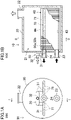
- the heat exchanger (10) of this embodiment includes a shell (20) and a plate stack (40).
- the plate stack (40) is housed in an internal space (21) of the shell (20).
- the heat exchanger (10) also includes a plurality of (in this embodiment, six) refrigerant introduction pipes (71) that constitute a supply structure (70), and one refrigerant distributor (30).
- the shell (20) is in the shape of a cylinder with both ends closed.
- the shell (20) is arranged so that its longitudinal direction coincides with a lateral direction.
- a refrigerant outlet (22) for emitting the refrigerant out of the internal space (21) of the shell (20) is provided at the top of the shell (20).
- the refrigerant outlet (22) is disposed near the right end of the shell (20) in FIG. 1 .
- the refrigerant outlet (22) is connected to a compressor of the refrigeration apparatus via a pipe.
- the shell (20) is provided with a heating medium inlet (23) and a heating medium outlet (24).
- the heating medium inlet (23) and the heating medium outlet (24) are tubular members. Each of the heating medium inlet (23) and the heating medium outlet (24) passes through the left end of the shell (20) in FIG. 1 and is connected to the plate stack (40).
- the heating medium inlet (23) is connected to a heating medium introduction path (43) of the plate stack (40) to supply the heating medium to the plate stack (40).
- the heating medium outlet (24) is connected to a heating medium emission path (44) of the plate stack (40) to emit the heating medium out of the plate stack (40).
- the plate stack (40) includes a plurality of heat transfer plates (50a, 50b) stacked together.
- the plate stack (40) is housed in the internal space (21) of the shell (20) so that the stacking direction of the heat transfer plates (50a, 50b) coincides with the lateral direction.
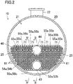
- the heat transfer plates (50a, 50b) constituting the plate stack (40) are substantially semicircular plate-shaped members.
- the plate stack (40) is arranged near the bottom of the internal space (21) of the shell (20) with arc-shaped edges of the heat transfer plates (50a, 50b) facing downward.
- supports in the shape of protrusions for supporting the plate stack (40) protrude from the interior surface of the shell (20).
- the plate stack (40) housed in the internal space (21) of the shell (20) is spaced apart from the inner surface of the shell (20), and forms a gap (25) between the downward-facing edges of the heat transfer plates (50a, 50b) of the plate stack (40) and the inner surface of the shell (20).
- the plate stack (40) includes first plates (50a) and second plates (50b) having different shapes as the heat transfer plates.
- the plate stack (40) includes a plurality of first plates (50a) and a plurality of second plates (50b).
- the first plates (50a) and the second plates (50b) are alternately stacked to form the plate stack (40).
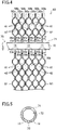
- a surface on the left in FIG. 3 will be referred to as a front surface
- a surface on the right in FIG. 3 will be referred to as a back surface.
- the plate stack (40) includes the refrigerant channels (41) and the heating medium channels (42), with the heat transfer plate (50a, 50b) interposed therebetween.
- the heat transfer plate (50a, 50b) separates the refrigerant channel (41) from the corresponding heating medium channel (42).
- Each of the refrigerant channels (41) is a channel sandwiched between the front surface of the first plate (50a) and the back surface of the second plate (50b).
- the refrigerant channel (41) communicates with the internal space (21) of the shell (20).
- Each of the heating medium channels (42) is a channel sandwiched between the back surface of the first plate (50a) and the front surface of the second plate (50b).
- the heating medium channel (42) is blocked from the internal space (21) of the shell (20), and communicates with the heating medium inlet (23) and the heating medium outlet (24) attached to the shell (20).
- each of the first plates (50a) and the second plates (50b) has multiple dimples (61).
- the dimples (61) of the first plate (50a) bulge toward the front side of the first plate (50a).
- the dimples (61) of the second plate (50b) bulge toward the back side of the second plate (50b).
- Each of the first plates (50a) has an inlet protrusion (51a) and an outlet protrusion (53a).
- Each of the inlet protrusion (51a) and the outlet protrusion (53a) is a circular portion bulging toward the front side of the first plate (50a).
- Each of the inlet protrusion (51a) and the outlet protrusion (53a) is formed in a widthwise center portion of the first plate (50a).
- the inlet protrusion (51a) is formed in a lower portion of the first plate (50a).
- the outlet protrusion (53a) is formed in an upper portion of the first plate (50a).
- a first inlet hole (52a) is formed in a center portion of the inlet protrusion (51a).
- a first outlet hole (54a) is formed in a center portion of the outlet protrusion (53a).
- Each of the first inlet hole (52a) and the first outlet hole (54a) is a circular hole penetrating the first plate (50a) in a thickness direction.
- Each of the second plates (50b) has an inlet recess (51b) and an outlet recess (53b).
- Each of the inlet recess (51b) and the outlet recess (53b) is a circular portion bulging toward the back side of the second plate (50b).
- Each of the inlet recess (51b) and the outlet recess (53b) is formed in a widthwise center portion of the second plate (50b).
- the inlet recess (51b) is formed in a lower portion of the second plate (50b).
- the outlet recess (53b) is formed in an upper portion of the second plate (50b).
- a second inlet hole (52b) is formed in a center portion of the inlet recess (51b).
- a second outlet hole (54b) is formed in a center portion of the outlet recess (53b).
- Each of the second inlet hole (52b) and the second outlet hole (54b) is a circular hole penetrating the second plate (50b) in a thickness direction.
- the inlet recess (51b) is formed at a position corresponding to the inlet protrusion (51a) of the first plate (50a), and the outlet recess (53b) is formed at a position corresponding to the outlet protrusion (53a) of the first plate (50a).
- the second inlet hole (52b) is formed at a position corresponding to the first inlet hole (52a) of the first plate (50a)
- the second outlet hole (54b) is formed at a position corresponding to the first outlet hole (54a) of the first plate (50a).
- the first inlet hole (52a) and the second inlet hole (52b) have a substantially equal diameter.
- the first outlet hole (54a) and the second outlet hole (54b) have a substantially equal diameter.
- each first plate (50a) and an adjacent one of the second plates (50b) on the back side of the first plate (50a) are welded together at their peripheral portions along the whole perimeter.
- the first inlet hole (52a) of each first plate (50a) overlaps the second inlet hole (52b) of an adjacent one of the second plates (50b) on the front side of the first plate (50a), and the rims of the overlapping first inlet hole (52a) and second inlet hole (52b) are welded together along the entire perimeter.
- the first outlet hole (54a) of each first plate (50a) overlaps the second outlet hole (54b) of an adjacent one of the second plates (50b) on the front side of the first plate (50a), and the rims of the overlapping first outlet hole (54a) and second outlet hole (54b) are welded together along the whole perimeter.
- the heating medium introduction path (43) and the heating medium emission path (44) are passages extending in the stacking direction of the heat transfer plates (50a, 50b) in the plate stack (40).
- the heating medium introduction path (43) is a passage blocked from the internal space (21) of the shell (20), and allows all the heating medium channels (42) to communicate with the heating medium inlet (23).
- the heating medium emission path (44) is a passage blocked from the internal space (21) of the shell (20), and allows all the heating medium channels (42) to communicate with the heating medium outlet (24).
- each of the first plates (50a) has a plurality of (in this embodiment, six) first circular holes (55a).
- the first circular hole (55a) is a circular hole penetrating the first plate (50a) in a thickness direction.
- the first plate (50a) has the same number of first flat portions (56a) as the number of first circular holes (55a).
- Each of the first flat portions (56a) is a flat portion surrounding the periphery of an associated one of the first circular holes (55a).
- the plurality of first circular holes (55a) are arranged in a row along the upper edge of the first plate (50a) in the width direction of the first plate (50a) (the lateral direction in FIG. 2 ).
- the plurality of first circular hole (55a) are arranged at predetermined intervals.
- the same number of (in this embodiment, three) first circular holes (55a) are formed in each of left and right side regions of the first outlet hole (54a) in FIG. 2 .
- the distance from the top of each of the first circular holes (55a) to the upper edge of the first plate (50a) is longer than the distance from the top of the first outlet hole (54a) to the upper edge of the first plate (50a).
- each of the second plates (50b) has a plurality of (in this embodiment, six) second circular holes (55b).
- the second circular hole (55b) is a circular hole penetrating the second plate (50b) in the thickness direction.
- the second plate (50b) has the same number of second flat portions (56b) as the number of second circular hole (55b).
- Each of the second flat portions (56b) is a flat portion surrounding the periphery of an associated one of the second circular holes (55b).
- the plurality of second circular holes (55b) are arranged in a row along the upper edge of the second plate (50b) in the width direction of the second plate (50b) (the lateral direction in FIG. 2 ).
- the plurality of second circular holes (55b) are arranged at predetermined intervals.
- the same number of (in this embodiment, three) second circular holes (55b) are formed in each of left and right side regions of the second outlet hole (54b) in FIG. 2 .
- the distance from the top of each of the second circular holes (55b) to the upper edge of the second plate (50b) is longer than the distance from the top of the second outlet hole (54b) to the upper edge of the second plate (50b).
- the second circular hole (55b) is formed at a position corresponding to the first circular hole (55a) of the first plate (50a).
- the first circular hole (55a) and the second circular hole (55b) have a substantially equal diameter.
- the first circular hole (55a) of each first plate (50a) overlaps the second circular hole (55b) of an adjacent one of the second plates (50b) on the back side of the first plate (50a), and the rims of the overlapping first circular hole (55a) and second circular hole (55b) are welded together along the whole perimeter.
- six refrigerant introduction pipes (71) constitute the supply structure (70) for supplying a refrigerant to the refrigerant channels (41) of the plate stack (40).
- each of the refrigerant introduction pipes (71) is a circular pipe members.
- the internal space of the refrigerant introduction pipe (71) is a refrigerant introduction channel (72).
- the refrigerant introduction pipe (71) passes through the plate stack (40) in a stacking direction of the heat transfer plates (50a, 50b).
- the distal end of the refrigerant introduction pipe (71) is closed.
- the base end of the refrigerant introduction pipe (71) passes through the left end of the shell (20) in FIG. 1 and is exposed to the outside of the shell (20).
- the refrigerant introduction pipe (71) is inserted in, and passes through, the first circular hole (55a) and the second circular hole (55b) of the overlapping first plate (50a) and second plate (50b). Each of the refrigerant introduction pipes (71) passes through the corresponding first circular hole (55a) and second circular hole (55b).
- the six refrigerant introduction pipes (71) are arranged such that their axial directions are substantially horizontal and substantially parallel to each other.
- the six refrigerant introduction pipes (71) are arranged in a row at predetermined intervals in the width direction of the heat transfer plate (50a, 50b).
- the refrigerant introduction pipe (71) has a plurality of (in this embodiment, three) supply holes (73) at each of portions where the refrigerant introduction pipe (71) crosses the refrigerant channels (41) of the plate stack (40).
- the supply holes (73) penetrate the refrigerant introduction pipe (71) in the radial direction to be open on inner and outer surfaces of the refrigerant introduction pipe (71).
- the supply holes (73) allow the refrigerant introduction channel (72), which is an interior of the refrigerant introduction pipe (71), to communicate with the refrigerant channels (41) on the outside of the refrigerant introduction pipe (71).
- the three supply holes (73) are formed downward at each of the portions of the refrigerant introduction pipe (71) crossing the refrigerant channels (41).
- the refrigerant introduction pipe (71) of this embodiment includes the supply hole (73) opening directly downward, the supply hole (73) opening diagonally down to the right, and the supply hole (73) opening diagonally down to the left at each of the portions crossing the refrigerant channels (41).
- the refrigerant distributor (30) is a member for distributing the refrigerant to be supplied to the heat exchanger (10) to all of the refrigerant introduction pipes (71).
- the refrigerant distributor (30) has a distributor body (31) and a refrigerant inlet (32), and is disposed outside the shell (20).
- the distributor body (31) is a hollow member, and is connected to the base end of each refrigerant introduction pipe (71) exposed to the outside of the shell (20).
- the refrigerant inlet (32) is a short circular pipe member, and is connected to the distributor body (31).
- the distributor body (31) distributes the refrigerant that has flowed in from the refrigerant inlet (32) to all of the refrigerant introduction pipes (71).
- the heat exchanger (10) receives a low-pressure refrigerant in a gas-liquid two-phase state that has passed through the expansion mechanism of the refrigerant circuit.
- the refrigerant to be supplied to the heat exchanger (10) flows into the distributor body (31) of the refrigerant distributor (30) from the refrigerant inlet (32), and is distributed to a plurality of (in this embodiment, six) refrigerant introduction pipes (71).
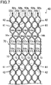
- each refrigerant introduction pipe (71) The refrigerant that has flowed into the refrigerant introduction channel (72) of each refrigerant introduction pipe (71) is supplied to the corresponding refrigerant channels (41) of the plate stack (40) through the supply holes (73). At this moment, the refrigerant is dispersed to the front surface of the first plate (50a) and the back surface of the second plate (50b) which define the refrigerant channel (41). Further, as illustrated in FIG. 6 , the refrigerant is dispersed downward in a circular sector from the three supply holes (73) for the respective refrigerant channels (41). In FIG. 6 , dimples (61) of the heat transfer plates (50a, 50b) are omitted.
- the refrigerant supplied to the refrigerant channels (41) flows down along the front surface of the first plate (50a) or the back surface of the second plate (50b), and while flowing down, absorbs heat from the heating medium flowing through the heating medium channels (42) and evaporates.
- the heat transfer plate (50a, 50b) of this embodiment has a lot of dimples (61).
- the liquid refrigerant flowing down along the heat transfer plate (50a, 50b) hits the dimples (61) and diffuses in the lateral direction.
- the liquid refrigerant that has not evaporated while flowing down along the heat transfer plate (50a, 50b) accumulates at the bottom of the internal space (21) of the shell (20). That is, a lower portion of the plate stack (40) is immersed in the liquid refrigerant. In the portion of the plate stack (40) immersed in the liquid refrigerant, the liquid refrigerant filling the refrigerant channels (41) is heated by the heating medium in the heating medium channels (42) and evaporates.
- the gas refrigerant generated in the refrigerant channels (41) flows upward in the refrigerant channels (41), passes between the refrigerant introduction pipes (71) arranged next to each other in the width direction of the heat transfer plate (50a, 50b), and flows into the space above the plate stack (40).
- Part of the gas refrigerant generated in the refrigerant channels (41) flows laterally into the gap (25) between the plate stack (40) and the shell (20), and flows into the space above the plate stack (40) through the gap (25).
- the refrigerant flowing into the space above the plate stack (40) contains a liquid refrigerant in the form of fine drops.
- the flow velocity of the refrigerant flowing through the space above the plate stack (40) is low because this space above the plate stack (40) is a relatively large space.
- most of the liquid refrigerant in the form of droplets in the refrigerant falls downward by gravity.
- the refrigerant that has flowed into the space above the plate stack (40) flows out of the shell (20) through the refrigerant outlet (22).
- the refrigerant flowed out of the shell (20) is sucked into the compressor of the refrigeration apparatus.
- the heating medium to be supplied to the heat exchanger (10) flows into the heating medium introduction path (43) of the plate stack (40) through the heating medium inlet (23), and is distributed to the heating medium channels (42).
- the heating medium that has flowed into each heating medium channel (42) flows generally upward while spreading in the width direction of the heat transfer plates (50a, 50b).
- the heating medium flowing in the heating medium channels (42) dissipates heat to the refrigerant flowing in the refrigerant channels (41). This lowers the temperature of the heating medium.
- each heating medium channel (42) flows into the heating medium emission path (44), and merges with the flows of the heating medium that have passed through the other heating medium channels (42). Thereafter, the heating medium in heating medium emission path (44) flows out of the heat exchanger (10) through the heating medium outlet (24), and is used for purposes such as air conditioning.
- the shell-and-plate heat exchanger (10) of this embodiment has the supply structure (70) for supplying the refrigerant to the refrigerant channels (41).
- the refrigerant supplied to the refrigerant channels (41) exchanges heat with the heating medium flowing through the heating medium channels (42) and evaporates, while flowing down along the heat transfer plates (50a, 50b).
- the shell-and-plate heat exchanger (10) of this embodiment functions as a falling film type evaporator.
- the supply structure (70) for supplying refrigerant to the plate stack (40) is disposed above the plate stack (40) in the shell (20). Placing the supply structure (70) above the plate stack (40) may narrow the space above the plate stack (40) in the shell (20) and increase the flow velocity of the refrigerant in the space above the plate stack (40).
- a gas refrigerant flowing upward from the plate stack (40) contains a liquid refrigerant in the form of droplets. As the flow velocity of the refrigerant in the space above the plate stack (40) increases, more droplets flow with the gas refrigerant without falling due to gravity. This increases the amount of liquid refrigerant flowing out of the shell (20) together with the gas refrigerant, impairing the performance of the heat exchanger (10).
- the supply structure (70) is located inside the outer peripheries of the heat transfer plates (50a, 50b) in the plate stack (40).
- This configuration ensures the space above the plate stack (40) in the shell (20) and keeps the flow velocity of the refrigerant in the space above the plate stack (40) low.
- the amount of liquid refrigerant flowing out of the shell (20) together with the gas refrigerant is kept small, improving the performance of the heat exchanger (10).
- the supply structure (70) of this embodiment includes the refrigerant introduction channel (72) and the supply holes (73).
- the refrigerant introduction channel (72) passes through the heat transfer plate (50a, 50b) of the plate stack (40).
- the supply holes (73) allow the refrigerant introduction channel (72) to communicate with the refrigerant channels (41) so that the refrigerant is supplied to the refrigerant channel (41).
- the refrigerant flowing through the refrigerant introduction channel (72) is supplied to the refrigerant channels (41) of the plate stack (40) through the supply holes (73).
- a plurality of supply holes (73) are provided for each of a plurality of refrigerant channels (41) formed in the plate stack (40).
- the refrigerant is supplied from the plurality of supply holes (73) to the corresponding one of the plurality of refrigerant channels (41) formed in the plate stack (40).
- the liquid refrigerant can be supplied to a wide area of the front surface or the back surface of the heat transfer plate (50a, 50b), making it possible to promote heat exchange between the refrigerant and the heating medium.
- the refrigerant introduction channel (72) is formed by the refrigerant introduction pipe (71).
- the refrigerant introduction pipe (71) passes through a plurality of heat transfer plates (50a, 50b) of the plate stack (40).
- the supply holes (73) penetrate the refrigerant introduction pipe (71) to be open on inner and outer surfaces of the refrigerant introduction pipe (71).
- the supply holes (73) are formed in the refrigerant introduction pipe (71) forming the refrigerant introduction channel (72).
- the supply holes (73) penetrate the refrigerant introduction pipe (71) and allow the refrigerant introduction channel (72) to communicate with the refrigerant channels (41).
- the heat exchanger (10) of this embodiment includes a plurality of supply structures (70).
- the plurality of supply structures (70) are arranged at predetermined intervals along upward-facing edges of the heat transfer plates (50a, 50b) of the plate stack (40).
- the heat exchanger (10) of this embodiment includes a plurality of supply structures (70).
- the plurality of supply structures (70) are arranged at predetermined intervals.
- the refrigerant that has exchanged heat with the heating medium and evaporated in the plate stack (40) passes between the plurality of supply structures (70) and flows into the space above the plate stack (40).
- the plate stack (40) of this embodiment includes the heating medium introduction path (43) and the heating medium emission path (44).
- Each of the heating medium introduction path (43) and the heating medium emission path (44) penetrates the heat transfer plates (50a, 50b) and communicates with the heating medium channels (42).
- Each of the heating medium introduction path (43) and the heating medium emission path (44) is formed at a widthwise center portion of the heat transfer plates (50a, 50b).
- the same number of supply structures (70) are provided in each of left and right side regions of the heating medium introduction path (43) and the heating medium emission path (44) in the width direction of the heat transfer plates (50a, 50b).
- the plate stack (40) of this embodiment includes the heating medium introduction path (43) and the heating medium emission path (44) at a widthwise center portion of the heat transfer plates (50a, 50b).
- the same number of supply structures (70) are provided in each of left and right side regions of the heating medium introduction path (43) and the heating medium emission path (44) in the width direction of the heat transfer plates (50a, 50b).
- the liquid refrigerant can be supplied from the supply structures (70) to a wide region of the surfaces of the heat transfer plates (50a, 50b).
- the heat exchanger (10) of this embodiment includes the refrigerant distributor (30) configured to distribute the refrigerant to the plurality of supply structures (70).
- the refrigerant to be supplied to the heat exchanger (10) of this embodiment is distributed to the plurality of supply structures (70) by the refrigerant distributor (30), and is supplied to the refrigerant channels (41) of the plate stack (40) from the respective supply structures (70).
- the heat exchanger (10) of this embodiment is configured such that the liquid refrigerant accumulates at the bottom of the internal space (21) of the shell (20).
- the plate stack (40) is provided at a position where a lower portion of the plate stack (40) is immersed in the liquid refrigerant accumulated at the bottom of the internal space (21).
- a lower portion of the plate stack (40) is immersed in the liquid refrigerant accumulated at the bottom of the internal space (21).
- the refrigerant supplied to the refrigerant channels (41) of the plate stack (40) from the supply structures (70) and the refrigerant accumulated at the bottom of the internal space (21) exchange heat with the heating medium in the heating medium channels (42) and evaporate.
- the plate stack (40) of this embodiment is positioned so as to leave a gap (25) between the downward-facing edges of the heat transfer plates (50a, 50b) and the interior surface of the shell (20).
- part of the refrigerant evaporated in the plate stack (40) flows upward through the refrigerant channels (41), while the rest of the refrigerant flows out of the refrigerant channels (41) into the gap (25) between the plate stack (40) and the shell (20) and flows upward through the gap (25). This facilitates the discharge of the gas refrigerant from the refrigerant channels (41) of the plate stack (40).
- the heat exchanger (10) of this embodiment is a heat exchanger (10) of the first embodiment with a modified supply structure (70).
- the following description will be focused on the differences between the heat exchanger (10) of this embodiment and the heat exchanger (10) of the first embodiment.
- the refrigerant introduction pipes (71) are omitted from the supply structure (70) of this embodiment, and the refrigerant introduction channel (72) is formed by the heat transfer plates (50a, 50b) of the plate stack (40).
- supply holes (73) are formed in the heat transfer plates (50a, 50b) of the plate stack (40).
- Each of the first plates (50a) of this embodiment has a plurality of (in this embodiment, six) circular protrusions (57a).
- Each of the circular protrusions (57a) is a circular portion bulging toward the front side of the first plate (50a).
- the first plate (50a) of this embodiment includes a first flat portion (56a) surrounding the periphery of an associated one of the circular protrusions (57a).
- each of the circular protrusions (57a) has a first circular hole (55a).
- the position of the first circular hole (55a) in the first plate (50a) of this embodiment is substantially the same as the position of the first circular hole (55a) in the first plate (50a) of the first embodiment.
- Each of the second plates (50b) of this embodiment has a plurality of (in this embodiment, six) circular recesses (57b).
- Each of the circular recesses (57b) is a circular portion bulging toward the back side of the second plate (50b).
- the second plate (50b) of this embodiment includes a second flat portion (56b) surrounding the periphery of an associated one of the circular recesses (57b).
- each of the circular recess (57b) has a second circular hole (55b).
- the position of the second circular hole (55b) in the second plate (50b) of this embodiment is substantially the same as the position of the second circular hole (55b) in the second plate (50b) of the first embodiment.
- the first circular hole (55a) and the second circular hole (55b) have a substantially equal diameter.
- the first circular hole (55a) of each first plate (50a) overlaps the second circular hole (55b) of an adjacent one of the second plates (50b) on the front side of the first plate (50a), and the rims of the overlapping first circular hole (55a) and second circular hole (55b) are welded together along the whole perimeter.
- the first flat portion (56a) of each first plate (50a) is in contact with the second flat portion (56b) of the second plate (50b) on the back side of the first plate (50a).
- the first flat portion (56a) and the second flat portion (56b) that are in contact with each other are joined by brazing.
- the first flat portion (56a) and the second flat portion (56b) that are in contact with each other may be joined by welding.
- the circular protrusions (57a) and first inlet holes (52a) of the first plates (50a) and the circular recesses (57b) and second inlet holes (52b) of the second plates (50b) form the refrigerant introduction channels (72).
- Each of the refrigerant introduction channels (72) is a passage extending in the stacking direction of the heat transfer plates (50a, 50b) in the plate stack (40).
- Each of the refrigerant introduction channels (72) is a passage blocked from the heating medium channels (42) of the plate stack (40) and the internal space (21) of the shell (20).
- the plurality of (in this embodiment, six) refrigerant introduction channels (72) in the plate stack (40) are connected to the distributor body (31) of the refrigerant distributor (30) via a pipe or the like.
- the supply holes (73) of this embodiment are formed in the heat transfer plates (50a, 50b).
- each first plate (50a) has the supply hole (73) at a lower part of an inclined portion of the circular protrusion (57a).
- the supply hole (73) penetrates the first plate (50a) in the thickness direction.
- the supply hole (73) is open to the front and back surfaces of the first plate (50a) and allows the refrigerant channel (41) defined by the front surface of the first plate (50a) to communicate with the refrigerant introduction channel (72).
- each second plate (50b) has the supply hole (73) at a lower part of an inclined portion of the circular recess (57b).
- the supply hole (73) penetrates the second plate (50b) in the thickness direction.
- the supply hole (73) is open to the front and back surfaces of the second plate (50b) and allows the refrigerant channel (41) defined by the back surface of the second plate (50b) to communicate with the refrigerant introduction channel (72).
- the refrigerant to be supplied to the heat exchanger (10) flows into the distributor body (31) of the refrigerant distributor (30) from the refrigerant inlet (32), and is distributed to a plurality of (in this embodiment, six) refrigerant introduction channels (72).
- the refrigerant that has flowed into the refrigerant introduction channels (72) is supplied to the corresponding refrigerant channels (41) of the plate stack (40) through the supply holes (73). At this moment, the refrigerant is dispersed to the front surface of the first plate (50a) and the back surface of the second plate (50b) which define the refrigerant channel (41).
- the refrigerant introduction channel (72) is formed by the plurality of heat transfer plates (50a, 50b) of the plate stack (40) joined together.
- the supply holes (73) penetrate the heat transfer plates (50a, 50b) and open on the front and back surfaces of the heat transfer plates (50a, 50b).
- the refrigerant introduction channel (72) is formed by the plurality of heat transfer plates (50a, 50b) joined together.
- the supply holes (73) penetrate the heat transfer plates (50a, 50b) and allow the refrigerant introduction channel (72) to communicate with the refrigerant channels (41).
- the heat exchanger (10) can have the supply structure (70) without using an additional member in the heat exchanger (10).
- the heat exchanger (10) of this embodiment is a heat exchanger (10) of the first embodiment with modified configurations of the plate stack (40) and the supply structure (70).
- the following description will be focused on the differences between the heat exchanger (10) of this embodiment and the heat exchanger (10) of the first embodiment.
- the supply structure (70) of the heat exchanger (10) of this embodiment is disposed above the plate stack (40) in the internal space (21) of the shell (20).
- the supply structure (70) of this embodiment is arranged at a position adjacent to the upper edges of the heat transfer plates (50a, 50b) constituting the plate stack (40).
- the heat transfer plates (50a, 50b) constituting the plate stack (40) differ from those of the first embodiment.
- the first circular hole (55a) and the first flat portion (56a) are omitted from the first plate (50a) of this embodiment.
- the second circular hole (55b) and the second flat portion (56b) are also omitted from the second plate (50b) of this embodiment.
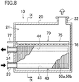
- the supply structure (70) of this embodiment includes one distribution tray (75), a plurality of disperse trays (76), and one inlet pipe (77).
- the distribution tray (75) is an elongated rectangular parallelepiped member with its upper side open.
- the length of the distribution tray (75) is substantially equal to the overall length of the plate stack (40), i.e., the length of the heat transfer plates (50a, 50b) in the stacking direction (see FIG. 8 ).
- the distribution tray (75) has a bottom plate with a plurality of distribution holes (75a).
- the number of the distribution holes (75a) is equal to the number of the disperse trays (76).
- Each of the distribution holes (75a) is a circular hole that penetrates the bottom plate of the distribution tray (75).
- the plurality of distribution holes (75a) are arranged in a row at regular intervals along the longitudinal direction of the distribution tray (75).
- the top of the distribution tray (75) may be closed.
- Each of the disperse trays (76) is an elongated rectangular parallelepiped member with its upper side open.
- the length of each disperse trays (76) is substantially equal to the overall width of the plate stack (40), i.e., the lateral width of the heat transfer plates (50a, 50b) (see FIG. 9 ).
- the disperse trays (76) each have a bottom plate with a plurality of disperse holes (76a).
- Each of the disperse holes (76a) is a circular hole that penetrates the bottom plate of the disperse trays (76).
- the plurality of disperse holes (76a) are arranged in a row at regular intervals along the longitudinal direction of the disperse trays (76).
- the top of each disperse trays (76) may be closed. However, even in that case, the portion of the top of the disperse tray (76) that is directly below the distribution tray (75) needs to be open.
- the plurality of disperse trays (76) are positioned below the distribution tray (75).
- the long side of each disperse tray (76) is substantially orthogonal to the long side of the distribution tray (75).
- the plurality of disperse trays (76) are arranged at regular intervals in the longitudinal direction of the distribution tray (75), with their long sides parallel to one another.
- the longitudinal center of each disperse tray (76) is located below a corresponding one of the distribution holes (75a). That is, in the supply structure (70), the disperse trays (76) correspond one-to-one with the distribution holes (75a).
- the inlet pipe (77) is a pipe for introducing the refrigerant supplied to the heat exchanger (10) into the distribution tray (75).
- the inlet pipe (77) is connected to a sidewall on one of short sides of the distribution tray (75) and penetrates this sidewall to be open to the inside of the distribution tray (75).
- the supply structure (70) of this embodiment is disposed above the plate stack (40).
- the supply structure (70) is arranged in the internal space (21) of the shell (20) such that the longitudinal direction of the distribution tray (75) is substantially parallel to the longitudinal direction of the shell (20).
- the inlet pipe (77) of the supply structure (70) penetrates the left end of the shell (20) in FIG. 8 and extends to the outside of the shell (20).
- the distribution tray (75) is disposed at the widthwise center of the plate stack (40).
- the disperse trays (76) are arranged along the upper edges of the heat transfer plates (50a, 50b) constituting the plate stack (40).
- the bottom surface of each of the disperse trays (76) faces the upper edge of the heat transfer plate (50a, 50b).
- the bottom surface of each of the disperse trays (76) is substantially parallel to the upper edge of the heat transfer plate (50a, 50b).
- the refrigerant to be supplied to the heat exchanger (10) flows through the inlet pipe (77) of the supply structure (70) into the distribution tray (75).
- the refrigerant that has flowed into the distribution tray (75) is distributed to each of the disperse trays (76). Specifically, the refrigerant that has flowed into the distribution tray (75) flows down through the distribution holes (75a) and into the disperse trays (76) corresponding to the respective distribution holes (75a).
- each of the disperse trays (76) from the distribution tray (75) flows down through the respective disperse holes (76a).
- Each of the disperse trays (76) provides the refrigerant for substantially the entire width of the plate stack (40).
- the refrigerant that has passed through the disperse holes of the disperse trays (76) flows into the refrigerant channels (41) of the plate stack (40), and exchanges heat with the heating medium and evaporates while flowing down along the heat transfer plates (50a, 50b).
- the heat exchanger (10) of the first to third embodiments may be modified into the following variations.
- the following variations may be combined or replaced without deteriorating the functions of the heat exchanger (10).
- the heat exchangers (10) of the first to third embodiments may include an eliminator (15).
- the eliminator (15) is a member for capturing droplets of the liquid refrigerant flowing together with the gas refrigerant.
- the eliminator (15) is in a thick plate shape made of a stack of metal meshes, for example, and allows the refrigerant to pass through in the thickness direction.
- the eliminator (15) is housed in the internal space (21) of the shell (20).
- the eliminator (15) is placed to traverse the internal space (21) of the shell (20) above the plate stack (40).
- the gas refrigerant moving toward the refrigerant outlet (22) from the plate stack (40) passes through the eliminator (15).
- the liquid refrigerant in the form of droplets contained in the gas refrigerant adheres to the eliminator (15) and is separated from the gas refrigerant.
- the gas refrigerant that has passed through the eliminator (15) flows out of the shell (20) through the refrigerant outlet (22).
- the liquid refrigerant captured by the eliminator (15) falls down in the form of relatively large droplets.
- the heat exchangers (10) of the first to third embodiments may include a gas-liquid separator (16).
- the gas-liquid separator (16) is a container-shaped member configured to separate the refrigerant in a gas-liquid two-phase state introduced therein into a liquid refrigerant and a gas refrigerant.
- a liquid outlet (17) is provided at the bottom of the gas-liquid separator (16).
- a gas outlet (18) is provided at the top of the gas-liquid separator (16).
- the gas-liquid separator (16) is housed in the internal space (21) of the shell (20), and is arranged above the plate stack (40).
- the refrigerant inlet (32) is connected to the gas-liquid separator (16).
- the refrigerant distributor (30) is housed in the internal space (21) of the shell (20).
- the liquid outlet (17) of the gas-liquid separator (16) is connected to the distributor body (31) of the refrigerant distributor (30) via a pipe.
- the gas outlet (18) of the gas-liquid separator (16) is open into the internal space (21) of the shell (20).
- the refrigerant in a gas-liquid two-phase state to be supplied to the heat exchanger (10) flows through the refrigerant inlet (32) into the gas-liquid separator (16) and is separated into a liquid refrigerant and a gas refrigerant.
- Liquid refrigerant in the gas-liquid separator (16) flows through the liquid outlet (17) into the refrigerant distributor (30) and is supplied to the refrigerant channels (41) of the plate stack (40).
- the gas refrigerant in the gas-liquid separator (16) flows through the gas outlet (18) into the internal space (21) of the shell (20), and flows out of the shell (20) from the refrigerant outlet (22) together with the gas refrigerant evaporated in the plate stack (40).
- each of the heat transfer plates (50a, 50b) forming the plate stack (40) may be provided with a corrugated pattern (62) including repeated narrow ridges and grooves instead of the dimples (61).
- the corrugated pattern (62) formed on the heat transfer plate (50a, 50b) may have the ridge lines and groove lines extending in the width direction of the heat transfer plate (50a, 50b).
- the corrugated pattern (62) formed on the heat transfer plate (50a, 50b) may be a pattern in which the ridges and grooves meander to the left and the right.
- the shape of the heat transfer plates (50a, 50b) forming the plate stack (40) is not limited to the semicircular shape.
- the heat transfer plate (50a, 50b) may have an elliptical shape.
- the heat transfer plate (50a, 50b) may have a circular shape.
- the heat transfer plates (50a, 50b) forming the plate stack (40) may be joined together by brazing.
- the present disclosure is useful for a shell-and-plate heat exchanger.
Landscapes
- Engineering & Computer Science (AREA)
- Physics & Mathematics (AREA)
- Thermal Sciences (AREA)
- Mechanical Engineering (AREA)
- General Engineering & Computer Science (AREA)
- Heat-Exchange Devices With Radiators And Conduit Assemblies (AREA)
Abstract
Description
- The present disclosure relates to a shell-and-plate heat exchanger.
- A shell-and-plate heat exchanger as disclosed by
Patent Document 1 has been known. This shell-and-plate heat exchanger includes a plate stack having a plurality of heat transfer plates and a shell housing the plate stack. - The heat exchanger of
Patent Document 1 is a flooded evaporator. In this heat exchanger, the plate stack is immersed in a liquid refrigerant stored in the shell. The liquid refrigerant in the shell evaporates when the liquid refrigerant exchanges heat with a heating medium flowing through the plate stack, and flows out of the shell through a refrigerant outlet formed in the top of the shell. - Patent Document 1:
Japanese Unexamined Patent Publication No. 2006-527835 - There is no shell-and-plate heat exchanger that functions as a falling film type evaporator. Thus, the application of the shell-and-plate heat exchanger has been limited.
- An object of the present disclosure is to expand the applications of shell-and-plate heat exchangers.
- A first aspect of the present disclosure is directed to a shell-and-plate heat exchanger (10) including: a shell (20) forming an internal space (21); and a plate stack (40) housed in the internal space (21) of the shell (20) and including a plurality of heat transfer plates (50a, 50b) stacked and joined together, the shell-and-plate heat exchanger allowing a refrigerant that has flowed into the internal space (21) of the shell (20) to evaporate. The plate stack (40) forms a plurality of refrigerant channels (41) that communicate with the internal space (21) of the shell (20) and allow a refrigerant to flow through and a plurality of heating medium channels (42) that are blocked from the internal space (21) of the shell (20) and allow a heating medium to flow through, each of the refrigerant channels (41) being adjacent to an associated one of the heating medium channels (42) with the heat transfer plate (50a, 50b) interposed therebetween, and the shell-and-plate heat exchanger includes a supply structure (70) configured to supply the refrigerant to the refrigerant channels (41) such that the refrigerant flows downward.
- According to the first aspect, the refrigerant is supplied from the supply structure (70) to the refrigerant channels (41) of the plate stack (40). The refrigerant supplied to the plate stack (40) by the supply structure (70) exchanges heat with the heating medium flowing through the heating medium channels (42) and evaporates, while flowing down through the refrigerant channels (41). The shell-and-plate heat exchanger (10) of this aspect serves as a falling film type evaporator.
- A second aspect of the present disclosure is an embodiment of the first aspect. In the second aspect, the supply structure (70) is located inside outer peripheries of the heat transfer plates (50a, 50b) in the plate stack (40).
- According to the second aspect, the supply structure (70) is located inside outer peripheries of the heat transfer plates (50a, 50b) in the plate stack (40). This configuration ensures the space above the plate stack (40) in the shell (20) and keeps the flow velocity of the refrigerant in the space above the plate stack (40) low. As a result, the amount of liquid refrigerant flowing out of the shell (20) together with the gas refrigerant is kept small, improving the performance of the shell-and-plate heat exchanger (10).
- A third aspect of the present disclosure is an embodiment of the second aspect. In the third aspect, the supply structure (70) includes a refrigerant introduction channel (72) that passes through the heat transfer plates (50a, 50b) of the plate stack (40), and a supply hole (73) that allows the refrigerant introduction channel (72) to communicate with the refrigerant channels (41) so that the refrigerant is supplied to the refrigerant channels (41).
- According to the third aspect, the supply structure (70) includes the refrigerant introduction channel (72) and the supply hole (73). In the supply structure (70), the refrigerant flowing through the refrigerant introduction channel (72) is supplied to the refrigerant channels (41) of the plate stack (40) through the supply hole (73).
- A fourth aspect of the present disclosure is an embodiment of the third aspect. In the fourth aspect, the supply hole (73) of the supply structure (70) includes a plurality of supply holes (73), the plurality of supply holes (73) being provided for each of the refrigerant channels (41) formed in the plate stack (40).
- According to the fourth aspect, the refrigerant is supplied from the plurality of supply holes (73) to the corresponding one of the plurality of refrigerant channels (41) formed in the plate stack (40). Thus, the liquid refrigerant can be supplied to a wide area of the front surface or the back surface of the heat transfer plate (50a, 50b), making it possible to promote heat exchange between the refrigerant and the heating medium.
- A fifth aspect of the present disclosure is an embodiment of the third or fourth aspect. In the fifth aspect, the refrigerant introduction channel (72) is formed by a refrigerant introduction pipe (71) that passes through the plurality of heat transfer plates (50a, 50b) of the plate stack (40), and the supply holes (73) penetrate the refrigerant introduction pipe (71) to be open on inner and outer surfaces of the refrigerant introduction pipe (71).
- According to the fifth aspect, the supply holes (73) are formed in the refrigerant introduction pipe (71) forming the refrigerant introduction channel (72). The supply holes (73) penetrate the refrigerant introduction pipe (71) and allow the refrigerant introduction channel (72) to communicate with the refrigerant channels (41).
- A sixth aspect of the present disclosure is an embodiment of the third or fourth aspect. In the sixth aspect, the refrigerant introduction channel (72) is formed by the plurality of heat transfer plates (50a, 50b) of the plate stack (40) joined together, and the supply holes (73) penetrate the heat transfer plates (50a, 50b) and open on front and back surfaces of the heat transfer plates (50a, 50b).
- According to the sixth aspect, the refrigerant introduction channel (72) is formed by the plurality of heat transfer plates (50a, 50b) joined together. The supply holes (73) penetrate the heat transfer plates (50a, 50b) and allow the refrigerant introduction channel (72) to communicate with the refrigerant channels (41).
- A seventh aspect of the present disclosure is an embodiment of any one of the second to sixth aspects. In the seventh aspect, the supply structure (70) includes a plurality of supply structures (70), the plurality of supply structures (70) being arranged at predetermined intervals along upward-facing edges of the heat transfer plates (50a, 50b) of the plate stack (40).
- According to the seventh aspect, the shell-and-plate heat exchanger (10) includes a plurality of supply structures (70). The plurality of supply structures (70) are arranged at predetermined intervals. The refrigerant that has exchanged heat with the heating medium and evaporated in the plate stack (40) passes between the plurality of supply structures (70) and flows into the space above the plate stack (40).
- An eighth aspect of the present disclosure is an embodiment of the seventh aspect. In the eighth aspect, the plate stack (40) includes a heating medium introduction path (43) and a heating medium emission path (44) at a widthwise center portion of the heat transfer plates (50a, 50b), the heating medium introduction path (43) and the heating medium emission path (44) passing through the heat transfer plates (50a, 50b) to communicate with the heating medium channels (42), and a same number of supply structures (70) are provided in each of left and right side regions of the heating medium introduction path (43) and the heating medium emission path (44) in a width direction of the heat transfer plates (50a, 50b).
- The plate stack (40) of the eighth aspect includes the heating medium introduction path (43) and the heating medium emission path (44) at a widthwise center portion of the heat transfer plates (50a, 50b). In this plate stack (40), the same number of supply structures (70) are provided in each of left and right side regions of the heating medium introduction path (43) and the heating medium emission path (44) in the width direction of the heat transfer plates (50a, 50b). Thus, the liquid refrigerant can be supplied from the supply structures (70) to a wide region of the surfaces of the heat transfer plates (50a, 50b).
- A ninth aspect of the present disclosure is an embodiment of the seventh or eighth aspect. In the ninth aspect, the shell-and-plate heat exchanger includes a refrigerant distributor (30) configured to distribute the refrigerant to the plurality of supply structures (70).
- In the ninth aspect, the refrigerant to be supplied to the shell-and-plate heat exchanger (10) is distributed to the plurality of supply structures (70) by the refrigerant distributor (30), and is supplied to the refrigerant channels (41) of the plate stack (40) from the respective supply structures (70).
- A tenth aspect of the present disclosure is an embodiment of any one of the first to ninth aspects. In the tenth aspect, the shell-and-plate heat exchanger is configured such that a liquid refrigerant accumulates at a bottom of the internal space (21) of the shell (20), and the plate stack (40) is provided at a position where a lower portion of the plate stack (40) is immersed in the liquid refrigerant accumulated at the bottom of the internal space (21).
- According to the tenth aspect, a lower portion of the plate stack (40) is immersed in the liquid refrigerant accumulated at the bottom of the internal space (21). In the internal space (21) of the shell (20), the refrigerant supplied to the refrigerant channels (41) of the plate stack (40) from the supply structures (70) and the refrigerant accumulated at the bottom of the internal space (21) exchange heat with the heating medium in the heating medium channels (42) and evaporate.
- An eleventh aspect of the present disclosure is an embodiment of any one of the first to tenth aspects. In the eleventh aspect, the plate stack (40) is positioned so as to leave a gap (25) between the downward-facing edges of the heat transfer plates (50a, 50b) and an interior surface of the shell (20).
- In the shell-and-plate heat exchanger (10) of the eleventh aspect, part of the refrigerant evaporated in the plate stack (40) flows upward through the refrigerant channels (41), while the rest of the refrigerant flows out of the refrigerant channels (41) into the gap (25) between the plate stack (40) and the shell (20) and flows upward through the gap (25). This facilitates the discharge of the gas refrigerant from the refrigerant channels (41) of the plate stack (40).
- A twelfth aspect of the present disclosure is an embodiment of any one of the first to eleventh aspects. In the twelfth aspect, the shell-and-plate heat exchanger includes a gas-liquid separator (16) configured to separate the refrigerant in a gas-liquid two-phase state into a liquid refrigerant and a gas refrigerant, supply the liquid refrigerant to the supply structures (70), and supply the gas refrigerant to the internal space (21) of the shell (20).
- According to the twelfth aspect, the gas-liquid separator (16) separates the refrigerant in a gas-liquid two-phase state into a liquid refrigerant and a gas refrigerant. The gas-liquid separator (16) supplies the liquid refrigerant to the supply structures (70) and the gas refrigerant to the internal space (21) of the shell (20). The liquid refrigerant supplied to the supply structures (70) from the gas-liquid separator (16) is supplied to the refrigerant channels (41) of the plate stack (40), exchanges heat with the heating medium, and evaporates. The gas refrigerant supplied to the internal space (21) of the shell (20) from the gas-liquid separator (16) flows out of the shell (20) together with the refrigerant that has evaporated by the heat exchange with the heating medium.
- A thirteenth aspect of the present disclosure is an embodiment of any one of the first to eleventh aspects. In the twelfth aspect, the shell (20) has a refrigerant outlet (22) at a top of the shell (20) for emitting the refrigerant in the internal space (21) out of the shell (20), and an eliminator (15) is provided in the internal space (21) of the shell (20), the eliminator (15) being placed to traverse between the plate stack (40) and the refrigerant outlet (22) and being configured to capture droplets of the liquid refrigerant contained in the refrigerant flowing from the plate stack (40) toward the refrigerant outlet (22).
- According to the thirteenth aspect, the eliminator (15) is provided in the internal space (21) of the shell (20). The liquid refrigerant in the form of droplets contained in the refrigerant moving toward the refrigerant outlet (22) from the plate stack (40) is captured by the eliminator (15) while passing through the eliminator (15).
-
-
FIG. 1A is a side view of a shell-and-plate heat exchanger of a first embodiment, andFIG. 1B is a cross-sectional view of the shell-and-plate heat exchanger taken along line I-I. -
FIG. 2 is a cross-sectional view of the shell-and-plate heat exchanger of the first embodiment taken along line II-II inFIG. 1 . -
FIG. 3 is a cross-sectional view of a plate stack taken along line III-III inFIG. 2 . -
FIG. 4 is a cross-sectional view of the plate stack taken along line IV-IV inFIG. 2 . -
FIG. 5 is a cross-sectional view of a refrigerant introduction pipe taken along line V-V inFIG. 4 . -
FIG. 6 is a cross-sectional view corresponding toFIG. 2 , illustrating a refrigerant flow in the shell-and-plate heat exchanger. -
FIG. 7 is a cross-sectional view of a plate stack of a second embodiment, which is a cross section corresponding toFIG. 3 . -
FIG. 8 is a cross-sectional view of a shell-and-plate heat exchanger of a third embodiment taken along line IX-IX inFIG. 9 . -
FIG. 9 is a cross-sectional view of the shell-and-plate heat exchanger of the third embodiment taken along line XIII-XIII inFIG. 8 . -
FIG. 10 is a plan view of a supply structure of the third embodiment. -
FIG. 11 is a cross-sectional view of the supply structure of the third embodiment taken along line XI-XI inFIG. 10 . -
FIG. 12 is a cross-sectional view of a shell-and-plate heat exchanger of a first variation of another embodiment, which is a cross section corresponding to I-I cross section ofFIG. 1 . -
FIG. 13 is a cross-sectional view of a shell-and-plate heat exchanger of a second variation of another embodiment, which is a cross section corresponding to I-I cross section ofFIG. 1 . -
FIG. 14 is a cross-sectional view of a shell-and-plate heat exchanger of a third variation of another embodiment, which is a cross section corresponding toFIG. 2 . -
FIG. 15 is a cross-sectional view of a shell-and-plate heat exchanger of a third variation of another embodiment, which is a cross section corresponding toFIG. 2 . -
FIG. 16 is a cross-sectional view of a shell-and-plate heat exchanger of a fourth variation of another embodiment, which is a cross section corresponding toFIG. 2 . - A first embodiment will be described. A shell-and-plate heat exchanger (10) (which will be hereinafter referred to as a "heat exchanger") of this embodiment is a falling film type evaporator. The heat exchanger (10) of this embodiment is provided in a refrigerant circuit of a refrigeration apparatus that performs a refrigeration cycle, and cools a heating medium with a refrigerant. Examples of the heating medium include water and brine.
- As illustrated in
FIG. 1 , the heat exchanger (10) of this embodiment includes a shell (20) and a plate stack (40). The plate stack (40) is housed in an internal space (21) of the shell (20). The heat exchanger (10) also includes a plurality of (in this embodiment, six) refrigerant introduction pipes (71) that constitute a supply structure (70), and one refrigerant distributor (30). - The shell (20) is in the shape of a cylinder with both ends closed. The shell (20) is arranged so that its longitudinal direction coincides with a lateral direction. A refrigerant outlet (22) for emitting the refrigerant out of the internal space (21) of the shell (20) is provided at the top of the shell (20). The refrigerant outlet (22) is disposed near the right end of the shell (20) in
FIG. 1 . The refrigerant outlet (22) is connected to a compressor of the refrigeration apparatus via a pipe. - The shell (20) is provided with a heating medium inlet (23) and a heating medium outlet (24). The heating medium inlet (23) and the heating medium outlet (24) are tubular members. Each of the heating medium inlet (23) and the heating medium outlet (24) passes through the left end of the shell (20) in
FIG. 1 and is connected to the plate stack (40). The heating medium inlet (23) is connected to a heating medium introduction path (43) of the plate stack (40) to supply the heating medium to the plate stack (40). The heating medium outlet (24) is connected to a heating medium emission path (44) of the plate stack (40) to emit the heating medium out of the plate stack (40). - As illustrated in
FIG. 1 , the plate stack (40) includes a plurality of heat transfer plates (50a, 50b) stacked together. The plate stack (40) is housed in the internal space (21) of the shell (20) so that the stacking direction of the heat transfer plates (50a, 50b) coincides with the lateral direction. - As illustrated in
FIG. 2 , the heat transfer plates (50a, 50b) constituting the plate stack (40) are substantially semicircular plate-shaped members. The plate stack (40) is arranged near the bottom of the internal space (21) of the shell (20) with arc-shaped edges of the heat transfer plates (50a, 50b) facing downward. - Although not shown, supports in the shape of protrusions for supporting the plate stack (40) protrude from the interior surface of the shell (20). The plate stack (40) housed in the internal space (21) of the shell (20) is spaced apart from the inner surface of the shell (20), and forms a gap (25) between the downward-facing edges of the heat transfer plates (50a, 50b) of the plate stack (40) and the inner surface of the shell (20).
- As illustrated in
FIG. 3 , the plate stack (40) includes first plates (50a) and second plates (50b) having different shapes as the heat transfer plates. The plate stack (40) includes a plurality of first plates (50a) and a plurality of second plates (50b). The first plates (50a) and the second plates (50b) are alternately stacked to form the plate stack (40). In the following description, for each of the first plates (50a) and the second plates (50b), a surface on the left inFIG. 3 will be referred to as a front surface, and a surface on the right inFIG. 3 will be referred to as a back surface. - As illustrated in
FIG. 3 , the plate stack (40) includes the refrigerant channels (41) and the heating medium channels (42), with the heat transfer plate (50a, 50b) interposed therebetween. The heat transfer plate (50a, 50b) separates the refrigerant channel (41) from the corresponding heating medium channel (42). - Each of the refrigerant channels (41) is a channel sandwiched between the front surface of the first plate (50a) and the back surface of the second plate (50b). The refrigerant channel (41) communicates with the internal space (21) of the shell (20). Each of the heating medium channels (42) is a channel sandwiched between the back surface of the first plate (50a) and the front surface of the second plate (50b). The heating medium channel (42) is blocked from the internal space (21) of the shell (20), and communicates with the heating medium inlet (23) and the heating medium outlet (24) attached to the shell (20).
- As illustrated in
FIGS. 2 and3 , each of the first plates (50a) and the second plates (50b) has multiple dimples (61). The dimples (61) of the first plate (50a) bulge toward the front side of the first plate (50a). The dimples (61) of the second plate (50b) bulge toward the back side of the second plate (50b). - Each of the first plates (50a) has an inlet protrusion (51a) and an outlet protrusion (53a). Each of the inlet protrusion (51a) and the outlet protrusion (53a) is a circular portion bulging toward the front side of the first plate (50a). Each of the inlet protrusion (51a) and the outlet protrusion (53a) is formed in a widthwise center portion of the first plate (50a). The inlet protrusion (51a) is formed in a lower portion of the first plate (50a). The outlet protrusion (53a) is formed in an upper portion of the first plate (50a). A first inlet hole (52a) is formed in a center portion of the inlet protrusion (51a). A first outlet hole (54a) is formed in a center portion of the outlet protrusion (53a). Each of the first inlet hole (52a) and the first outlet hole (54a) is a circular hole penetrating the first plate (50a) in a thickness direction.
- Each of the second plates (50b) has an inlet recess (51b) and an outlet recess (53b). Each of the inlet recess (51b) and the outlet recess (53b) is a circular portion bulging toward the back side of the second plate (50b). Each of the inlet recess (51b) and the outlet recess (53b) is formed in a widthwise center portion of the second plate (50b). The inlet recess (51b) is formed in a lower portion of the second plate (50b). The outlet recess (53b) is formed in an upper portion of the second plate (50b). A second inlet hole (52b) is formed in a center portion of the inlet recess (51b). A second outlet hole (54b) is formed in a center portion of the outlet recess (53b). Each of the second inlet hole (52b) and the second outlet hole (54b) is a circular hole penetrating the second plate (50b) in a thickness direction.
- In the second plate (50b), the inlet recess (51b) is formed at a position corresponding to the inlet protrusion (51a) of the first plate (50a), and the outlet recess (53b) is formed at a position corresponding to the outlet protrusion (53a) of the first plate (50a). In the second plate (50b), the second inlet hole (52b) is formed at a position corresponding to the first inlet hole (52a) of the first plate (50a), and the second outlet hole (54b) is formed at a position corresponding to the first outlet hole (54a) of the first plate (50a). The first inlet hole (52a) and the second inlet hole (52b) have a substantially equal diameter. The first outlet hole (54a) and the second outlet hole (54b) have a substantially equal diameter.
- In the plate stack (40), each first plate (50a) and an adjacent one of the second plates (50b) on the back side of the first plate (50a) are welded together at their peripheral portions along the whole perimeter. In the plate stack (40), the first inlet hole (52a) of each first plate (50a) overlaps the second inlet hole (52b) of an adjacent one of the second plates (50b) on the front side of the first plate (50a), and the rims of the overlapping first inlet hole (52a) and second inlet hole (52b) are welded together along the entire perimeter. In the plate stack (40), the first outlet hole (54a) of each first plate (50a) overlaps the second outlet hole (54b) of an adjacent one of the second plates (50b) on the front side of the first plate (50a), and the rims of the overlapping first outlet hole (54a) and second outlet hole (54b) are welded together along the whole perimeter.
- In the plate stack (40), the inlet protrusions (51a) and first inlet holes (52a) of the first plates (50a) and the inlet recesses (51b) and second inlet holes (52b) of the second plates (50b) form the heating medium introduction path (43). In the plate stack (40), the outlet protrusions (53a) and first outlet holes (54a) of the first plates (50a) and the outlet recesses (53b) and second outlet holes (54b) of the second plates (50b) form the heating medium emission path (44).
- The heating medium introduction path (43) and the heating medium emission path (44) are passages extending in the stacking direction of the heat transfer plates (50a, 50b) in the plate stack (40). The heating medium introduction path (43) is a passage blocked from the internal space (21) of the shell (20), and allows all the heating medium channels (42) to communicate with the heating medium inlet (23). The heating medium emission path (44) is a passage blocked from the internal space (21) of the shell (20), and allows all the heating medium channels (42) to communicate with the heating medium outlet (24).
- As illustrated in
FIGS. 2 and4 , each of the first plates (50a) has a plurality of (in this embodiment, six) first circular holes (55a). The first circular hole (55a) is a circular hole penetrating the first plate (50a) in a thickness direction. The first plate (50a) has the same number of first flat portions (56a) as the number of first circular holes (55a). Each of the first flat portions (56a) is a flat portion surrounding the periphery of an associated one of the first circular holes (55a). - As illustrated in
FIG. 2 , the plurality of first circular holes (55a) are arranged in a row along the upper edge of the first plate (50a) in the width direction of the first plate (50a) (the lateral direction inFIG. 2 ). The plurality of first circular hole (55a) are arranged at predetermined intervals. In the first plate (50a), the same number of (in this embodiment, three) first circular holes (55a) are formed in each of left and right side regions of the first outlet hole (54a) inFIG. 2 . The distance from the top of each of the first circular holes (55a) to the upper edge of the first plate (50a) is longer than the distance from the top of the first outlet hole (54a) to the upper edge of the first plate (50a). - As illustrated in
FIGS. 2 and4 , each of the second plates (50b) has a plurality of (in this embodiment, six) second circular holes (55b). The second circular hole (55b) is a circular hole penetrating the second plate (50b) in the thickness direction. The second plate (50b) has the same number of second flat portions (56b) as the number of second circular hole (55b). Each of the second flat portions (56b) is a flat portion surrounding the periphery of an associated one of the second circular holes (55b). - As illustrated in
FIG. 2 , the plurality of second circular holes (55b) are arranged in a row along the upper edge of the second plate (50b) in the width direction of the second plate (50b) (the lateral direction inFIG. 2 ). The plurality of second circular holes (55b) are arranged at predetermined intervals. In the second plate (50b), the same number of (in this embodiment, three) second circular holes (55b) are formed in each of left and right side regions of the second outlet hole (54b) inFIG. 2 . The distance from the top of each of the second circular holes (55b) to the upper edge of the second plate (50b) is longer than the distance from the top of the second outlet hole (54b) to the upper edge of the second plate (50b). - In the second plate (50b), the second circular hole (55b) is formed at a position corresponding to the first circular hole (55a) of the first plate (50a). The first circular hole (55a) and the second circular hole (55b) have a substantially equal diameter. In the plate stack (40), the first circular hole (55a) of each first plate (50a) overlaps the second circular hole (55b) of an adjacent one of the second plates (50b) on the back side of the first plate (50a), and the rims of the overlapping first circular hole (55a) and second circular hole (55b) are welded together along the whole perimeter.
- In the heat exchanger (10) of the present embodiment, six refrigerant introduction pipes (71) constitute the supply structure (70) for supplying a refrigerant to the refrigerant channels (41) of the plate stack (40).
- As illustrated in
FIGS. 1 and4 , each of the refrigerant introduction pipes (71) is a circular pipe members. The internal space of the refrigerant introduction pipe (71) is a refrigerant introduction channel (72). As illustrated inFIG. 1 , the refrigerant introduction pipe (71) passes through the plate stack (40) in a stacking direction of the heat transfer plates (50a, 50b). The distal end of the refrigerant introduction pipe (71) is closed. The base end of the refrigerant introduction pipe (71) passes through the left end of the shell (20) inFIG. 1 and is exposed to the outside of the shell (20). - As illustrated in
FIGS. 2 and4 , the refrigerant introduction pipe (71) is inserted in, and passes through, the first circular hole (55a) and the second circular hole (55b) of the overlapping first plate (50a) and second plate (50b). Each of the refrigerant introduction pipes (71) passes through the corresponding first circular hole (55a) and second circular hole (55b). In the plate stack (40) of this embodiment, the six refrigerant introduction pipes (71) are arranged such that their axial directions are substantially horizontal and substantially parallel to each other. The six refrigerant introduction pipes (71) are arranged in a row at predetermined intervals in the width direction of the heat transfer plate (50a, 50b). - As illustrated in
FIG. 4 , the refrigerant introduction pipe (71) has a plurality of (in this embodiment, three) supply holes (73) at each of portions where the refrigerant introduction pipe (71) crosses the refrigerant channels (41) of the plate stack (40). The supply holes (73) penetrate the refrigerant introduction pipe (71) in the radial direction to be open on inner and outer surfaces of the refrigerant introduction pipe (71). The supply holes (73) allow the refrigerant introduction channel (72), which is an interior of the refrigerant introduction pipe (71), to communicate with the refrigerant channels (41) on the outside of the refrigerant introduction pipe (71). - As illustrated in
FIG. 5 , the three supply holes (73) are formed downward at each of the portions of the refrigerant introduction pipe (71) crossing the refrigerant channels (41). The refrigerant introduction pipe (71) of this embodiment includes the supply hole (73) opening directly downward, the supply hole (73) opening diagonally down to the right, and the supply hole (73) opening diagonally down to the left at each of the portions crossing the refrigerant channels (41). - The refrigerant distributor (30) is a member for distributing the refrigerant to be supplied to the heat exchanger (10) to all of the refrigerant introduction pipes (71).
- As illustrated in
FIG. 1 , the refrigerant distributor (30) has a distributor body (31) and a refrigerant inlet (32), and is disposed outside the shell (20). The distributor body (31) is a hollow member, and is connected to the base end of each refrigerant introduction pipe (71) exposed to the outside of the shell (20). The refrigerant inlet (32) is a short circular pipe member, and is connected to the distributor body (31). The distributor body (31) distributes the refrigerant that has flowed in from the refrigerant inlet (32) to all of the refrigerant introduction pipes (71). - Flows of the refrigerant and the heating medium in the heat exchanger (10) of this embodiment will be described below.
- The heat exchanger (10) receives a low-pressure refrigerant in a gas-liquid two-phase state that has passed through the expansion mechanism of the refrigerant circuit. The refrigerant to be supplied to the heat exchanger (10) flows into the distributor body (31) of the refrigerant distributor (30) from the refrigerant inlet (32), and is distributed to a plurality of (in this embodiment, six) refrigerant introduction pipes (71).
- The refrigerant that has flowed into the refrigerant introduction channel (72) of each refrigerant introduction pipe (71) is supplied to the corresponding refrigerant channels (41) of the plate stack (40) through the supply holes (73). At this moment, the refrigerant is dispersed to the front surface of the first plate (50a) and the back surface of the second plate (50b) which define the refrigerant channel (41). Further, as illustrated in
FIG. 6 , the refrigerant is dispersed downward in a circular sector from the three supply holes (73) for the respective refrigerant channels (41). InFIG. 6 , dimples (61) of the heat transfer plates (50a, 50b) are omitted. - The refrigerant supplied to the refrigerant channels (41) flows down along the front surface of the first plate (50a) or the back surface of the second plate (50b), and while flowing down, absorbs heat from the heating medium flowing through the heating medium channels (42) and evaporates. The heat transfer plate (50a, 50b) of this embodiment has a lot of dimples (61). The liquid refrigerant flowing down along the heat transfer plate (50a, 50b) hits the dimples (61) and diffuses in the lateral direction. This means that a region of the front surface or the back surface of the heat transfer plate (50a, 50b) that comes into contact with the liquid refrigerant is enlarged, and that the liquid refrigerant stays on the front surface or the back surface of the heat transfer plate (50a, 50b) for a longer time.
- As illustrated in
FIG. 6 , the liquid refrigerant that has not evaporated while flowing down along the heat transfer plate (50a, 50b) accumulates at the bottom of the internal space (21) of the shell (20). That is, a lower portion of the plate stack (40) is immersed in the liquid refrigerant. In the portion of the plate stack (40) immersed in the liquid refrigerant, the liquid refrigerant filling the refrigerant channels (41) is heated by the heating medium in the heating medium channels (42) and evaporates. - As indicated by the arrows in
FIG. 6 , the gas refrigerant generated in the refrigerant channels (41) flows upward in the refrigerant channels (41), passes between the refrigerant introduction pipes (71) arranged next to each other in the width direction of the heat transfer plate (50a, 50b), and flows into the space above the plate stack (40). Part of the gas refrigerant generated in the refrigerant channels (41) flows laterally into the gap (25) between the plate stack (40) and the shell (20), and flows into the space above the plate stack (40) through the gap (25). - The refrigerant flowing into the space above the plate stack (40) contains a liquid refrigerant in the form of fine drops. On the other hand, the flow velocity of the refrigerant flowing through the space above the plate stack (40) is low because this space above the plate stack (40) is a relatively large space. Thus, most of the liquid refrigerant in the form of droplets in the refrigerant falls downward by gravity. The refrigerant that has flowed into the space above the plate stack (40) flows out of the shell (20) through the refrigerant outlet (22). The refrigerant flowed out of the shell (20) is sucked into the compressor of the refrigeration apparatus.
- The heating medium to be supplied to the heat exchanger (10) flows into the heating medium introduction path (43) of the plate stack (40) through the heating medium inlet (23), and is distributed to the heating medium channels (42). The heating medium that has flowed into each heating medium channel (42) flows generally upward while spreading in the width direction of the heat transfer plates (50a, 50b). The heating medium flowing in the heating medium channels (42) dissipates heat to the refrigerant flowing in the refrigerant channels (41). This lowers the temperature of the heating medium.
- The heating medium cooled while flowing through each heating medium channel (42) flows into the heating medium emission path (44), and merges with the flows of the heating medium that have passed through the other heating medium channels (42). Thereafter, the heating medium in heating medium emission path (44) flows out of the heat exchanger (10) through the heating medium outlet (24), and is used for purposes such as air conditioning.
- The shell-and-plate heat exchanger (10) of this embodiment has the supply structure (70) for supplying the refrigerant to the refrigerant channels (41). The refrigerant supplied to the refrigerant channels (41) exchanges heat with the heating medium flowing through the heating medium channels (42) and evaporates, while flowing down along the heat transfer plates (50a, 50b). The shell-and-plate heat exchanger (10) of this embodiment functions as a falling film type evaporator.
- Suppose that in a shell-and-plate heat exchanger used as a falling film type evaporator, the supply structure (70) for supplying refrigerant to the plate stack (40) is disposed above the plate stack (40) in the shell (20). Placing the supply structure (70) above the plate stack (40) may narrow the space above the plate stack (40) in the shell (20) and increase the flow velocity of the refrigerant in the space above the plate stack (40).
- A gas refrigerant flowing upward from the plate stack (40) contains a liquid refrigerant in the form of droplets. As the flow velocity of the refrigerant in the space above the plate stack (40) increases, more droplets flow with the gas refrigerant without falling due to gravity. This increases the amount of liquid refrigerant flowing out of the shell (20) together with the gas refrigerant, impairing the performance of the heat exchanger (10).
- On the other hand, in the heat exchanger (10) of this embodiment, the supply structure (70) is located inside the outer peripheries of the heat transfer plates (50a, 50b) in the plate stack (40). This configuration ensures the space above the plate stack (40) in the shell (20) and keeps the flow velocity of the refrigerant in the space above the plate stack (40) low. As a result, the amount of liquid refrigerant flowing out of the shell (20) together with the gas refrigerant is kept small, improving the performance of the heat exchanger (10).
- The supply structure (70) of this embodiment includes the refrigerant introduction channel (72) and the supply holes (73). The refrigerant introduction channel (72) passes through the heat transfer plate (50a, 50b) of the plate stack (40). The supply holes (73) allow the refrigerant introduction channel (72) to communicate with the refrigerant channels (41) so that the refrigerant is supplied to the refrigerant channel (41).
- In the supply structure (70) of this embodiment, the refrigerant flowing through the refrigerant introduction channel (72) is supplied to the refrigerant channels (41) of the plate stack (40) through the supply holes (73).
- In the supply structure (70) of this embodiment, a plurality of supply holes (73) are provided for each of a plurality of refrigerant channels (41) formed in the plate stack (40).
- In the heat exchanger (10) of this embodiment, the refrigerant is supplied from the plurality of supply holes (73) to the corresponding one of the plurality of refrigerant channels (41) formed in the plate stack (40). Thus, the liquid refrigerant can be supplied to a wide area of the front surface or the back surface of the heat transfer plate (50a, 50b), making it possible to promote heat exchange between the refrigerant and the heating medium.
- In the supply structure (70) of this embodiment, the refrigerant introduction channel (72) is formed by the refrigerant introduction pipe (71). The refrigerant introduction pipe (71) passes through a plurality of heat transfer plates (50a, 50b) of the plate stack (40). The supply holes (73) penetrate the refrigerant introduction pipe (71) to be open on inner and outer surfaces of the refrigerant introduction pipe (71).
- In the supply structure (70) of this embodiment, the supply holes (73) are formed in the refrigerant introduction pipe (71) forming the refrigerant introduction channel (72). The supply holes (73) penetrate the refrigerant introduction pipe (71) and allow the refrigerant introduction channel (72) to communicate with the refrigerant channels (41).
- The heat exchanger (10) of this embodiment includes a plurality of supply structures (70). The plurality of supply structures (70) are arranged at predetermined intervals along upward-facing edges of the heat transfer plates (50a, 50b) of the plate stack (40).
- The heat exchanger (10) of this embodiment includes a plurality of supply structures (70). The plurality of supply structures (70) are arranged at predetermined intervals. The refrigerant that has exchanged heat with the heating medium and evaporated in the plate stack (40) passes between the plurality of supply structures (70) and flows into the space above the plate stack (40).
- The plate stack (40) of this embodiment includes the heating medium introduction path (43) and the heating medium emission path (44). Each of the heating medium introduction path (43) and the heating medium emission path (44) penetrates the heat transfer plates (50a, 50b) and communicates with the heating medium channels (42). Each of the heating medium introduction path (43) and the heating medium emission path (44) is formed at a widthwise center portion of the heat transfer plates (50a, 50b). The same number of supply structures (70) are provided in each of left and right side regions of the heating medium introduction path (43) and the heating medium emission path (44) in the width direction of the heat transfer plates (50a, 50b).
- The plate stack (40) of this embodiment includes the heating medium introduction path (43) and the heating medium emission path (44) at a widthwise center portion of the heat transfer plates (50a, 50b). In this plate stack (40), the same number of supply structures (70) are provided in each of left and right side regions of the heating medium introduction path (43) and the heating medium emission path (44) in the width direction of the heat transfer plates (50a, 50b). Thus, the liquid refrigerant can be supplied from the supply structures (70) to a wide region of the surfaces of the heat transfer plates (50a, 50b).
- The heat exchanger (10) of this embodiment includes the refrigerant distributor (30) configured to distribute the refrigerant to the plurality of supply structures (70).
- The refrigerant to be supplied to the heat exchanger (10) of this embodiment is distributed to the plurality of supply structures (70) by the refrigerant distributor (30), and is supplied to the refrigerant channels (41) of the plate stack (40) from the respective supply structures (70).
- The heat exchanger (10) of this embodiment is configured such that the liquid refrigerant accumulates at the bottom of the internal space (21) of the shell (20). The plate stack (40) is provided at a position where a lower portion of the plate stack (40) is immersed in the liquid refrigerant accumulated at the bottom of the internal space (21).
- In the heat exchanger (10) of this embodiment, a lower portion of the plate stack (40) is immersed in the liquid refrigerant accumulated at the bottom of the internal space (21). In the internal space (21) of the shell (20), the refrigerant supplied to the refrigerant channels (41) of the plate stack (40) from the supply structures (70) and the refrigerant accumulated at the bottom of the internal space (21) exchange heat with the heating medium in the heating medium channels (42) and evaporate.
- The plate stack (40) of this embodiment is positioned so as to leave a gap (25) between the downward-facing edges of the heat transfer plates (50a, 50b) and the interior surface of the shell (20).
- In the heat exchanger (10) of this embodiment, part of the refrigerant evaporated in the plate stack (40) flows upward through the refrigerant channels (41), while the rest of the refrigerant flows out of the refrigerant channels (41) into the gap (25) between the plate stack (40) and the shell (20) and flows upward through the gap (25). This facilitates the discharge of the gas refrigerant from the refrigerant channels (41) of the plate stack (40).
- A second embodiment will be described. The heat exchanger (10) of this embodiment is a heat exchanger (10) of the first embodiment with a modified supply structure (70). Thus, the following description will be focused on the differences between the heat exchanger (10) of this embodiment and the heat exchanger (10) of the first embodiment.
- As illustrated in
FIG. 7 , the refrigerant introduction pipes (71) are omitted from the supply structure (70) of this embodiment, and the refrigerant introduction channel (72) is formed by the heat transfer plates (50a, 50b) of the plate stack (40). In the supply structure (70) of this embodiment, supply holes (73) are formed in the heat transfer plates (50a, 50b) of the plate stack (40). - Each of the first plates (50a) of this embodiment has a plurality of (in this embodiment, six) circular protrusions (57a). Each of the circular protrusions (57a) is a circular portion bulging toward the front side of the first plate (50a). The first plate (50a) of this embodiment includes a first flat portion (56a) surrounding the periphery of an associated one of the circular protrusions (57a). In the first plate (50a) of this embodiment, each of the circular protrusions (57a) has a first circular hole (55a). The position of the first circular hole (55a) in the first plate (50a) of this embodiment is substantially the same as the position of the first circular hole (55a) in the first plate (50a) of the first embodiment.
- Each of the second plates (50b) of this embodiment has a plurality of (in this embodiment, six) circular recesses (57b). Each of the circular recesses (57b) is a circular portion bulging toward the back side of the second plate (50b). The second plate (50b) of this embodiment includes a second flat portion (56b) surrounding the periphery of an associated one of the circular recesses (57b). In the second plate (50b) of this embodiment, each of the circular recess (57b) has a second circular hole (55b). The position of the second circular hole (55b) in the second plate (50b) of this embodiment is substantially the same as the position of the second circular hole (55b) in the second plate (50b) of the first embodiment.
- Similarly to the plate stack (40) of the first embodiment, the first circular hole (55a) and the second circular hole (55b) have a substantially equal diameter. In the plate stack (40) of this embodiment, the first circular hole (55a) of each first plate (50a) overlaps the second circular hole (55b) of an adjacent one of the second plates (50b) on the front side of the first plate (50a), and the rims of the overlapping first circular hole (55a) and second circular hole (55b) are welded together along the whole perimeter.
- In the plate stack (40) of this embodiment, the first flat portion (56a) of each first plate (50a) is in contact with the second flat portion (56b) of the second plate (50b) on the back side of the first plate (50a). The first flat portion (56a) and the second flat portion (56b) that are in contact with each other are joined by brazing. The first flat portion (56a) and the second flat portion (56b) that are in contact with each other may be joined by welding.
- In the plate stack (40) of this embodiment, the circular protrusions (57a) and first inlet holes (52a) of the first plates (50a) and the circular recesses (57b) and second inlet holes (52b) of the second plates (50b) form the refrigerant introduction channels (72). Each of the refrigerant introduction channels (72) is a passage extending in the stacking direction of the heat transfer plates (50a, 50b) in the plate stack (40). Each of the refrigerant introduction channels (72) is a passage blocked from the heating medium channels (42) of the plate stack (40) and the internal space (21) of the shell (20). The plurality of (in this embodiment, six) refrigerant introduction channels (72) in the plate stack (40) are connected to the distributor body (31) of the refrigerant distributor (30) via a pipe or the like.
- As illustrated in
FIG. 7 , the supply holes (73) of this embodiment are formed in the heat transfer plates (50a, 50b). - Specifically, each first plate (50a) has the supply hole (73) at a lower part of an inclined portion of the circular protrusion (57a). The supply hole (73) penetrates the first plate (50a) in the thickness direction. The supply hole (73) is open to the front and back surfaces of the first plate (50a) and allows the refrigerant channel (41) defined by the front surface of the first plate (50a) to communicate with the refrigerant introduction channel (72).
- Further, each second plate (50b) has the supply hole (73) at a lower part of an inclined portion of the circular recess (57b). The supply hole (73) penetrates the second plate (50b) in the thickness direction. The supply hole (73) is open to the front and back surfaces of the second plate (50b) and allows the refrigerant channel (41) defined by the back surface of the second plate (50b) to communicate with the refrigerant introduction channel (72).
- The refrigerant to be supplied to the heat exchanger (10) flows into the distributor body (31) of the refrigerant distributor (30) from the refrigerant inlet (32), and is distributed to a plurality of (in this embodiment, six) refrigerant introduction channels (72). The refrigerant that has flowed into the refrigerant introduction channels (72) is supplied to the corresponding refrigerant channels (41) of the plate stack (40) through the supply holes (73). At this moment, the refrigerant is dispersed to the front surface of the first plate (50a) and the back surface of the second plate (50b) which define the refrigerant channel (41).
- In the supply structure (70) of this embodiment, the refrigerant introduction channel (72) is formed by the plurality of heat transfer plates (50a, 50b) of the plate stack (40) joined together. In this supply structure (70), the supply holes (73) penetrate the heat transfer plates (50a, 50b) and open on the front and back surfaces of the heat transfer plates (50a, 50b).
- In the supply structure (70) of this embodiment, the refrigerant introduction channel (72) is formed by the plurality of heat transfer plates (50a, 50b) joined together. The supply holes (73) penetrate the heat transfer plates (50a, 50b) and allow the refrigerant introduction channel (72) to communicate with the refrigerant channels (41). Thus, according to this embodiment, the heat exchanger (10) can have the supply structure (70) without using an additional member in the heat exchanger (10).
- The third embodiment will be described. The heat exchanger (10) of this embodiment is a heat exchanger (10) of the first embodiment with modified configurations of the plate stack (40) and the supply structure (70). Thus, the following description will be focused on the differences between the heat exchanger (10) of this embodiment and the heat exchanger (10) of the first embodiment.
- As illustrated in
FIGS. 8 and9 , the supply structure (70) of the heat exchanger (10) of this embodiment is disposed above the plate stack (40) in the internal space (21) of the shell (20). The supply structure (70) of this embodiment is arranged at a position adjacent to the upper edges of the heat transfer plates (50a, 50b) constituting the plate stack (40). - As illustrated in
FIG. 9 , in the heat exchanger (10) of this embodiment, the heat transfer plates (50a, 50b) constituting the plate stack (40) differ from those of the first embodiment. The first circular hole (55a) and the first flat portion (56a) are omitted from the first plate (50a) of this embodiment. The second circular hole (55b) and the second flat portion (56b) are also omitted from the second plate (50b) of this embodiment. - As illustrated in
FIGS. 10 and 11 , the supply structure (70) of this embodiment includes one distribution tray (75), a plurality of disperse trays (76), and one inlet pipe (77). - The distribution tray (75) is an elongated rectangular parallelepiped member with its upper side open. The length of the distribution tray (75) is substantially equal to the overall length of the plate stack (40), i.e., the length of the heat transfer plates (50a, 50b) in the stacking direction (see
FIG. 8 ). The distribution tray (75) has a bottom plate with a plurality of distribution holes (75a). The number of the distribution holes (75a) is equal to the number of the disperse trays (76). Each of the distribution holes (75a) is a circular hole that penetrates the bottom plate of the distribution tray (75). The plurality of distribution holes (75a) are arranged in a row at regular intervals along the longitudinal direction of the distribution tray (75). The top of the distribution tray (75) may be closed. - Each of the disperse trays (76) is an elongated rectangular parallelepiped member with its upper side open. The length of each disperse trays (76) is substantially equal to the overall width of the plate stack (40), i.e., the lateral width of the heat transfer plates (50a, 50b) (see
FIG. 9 ). The disperse trays (76) each have a bottom plate with a plurality of disperse holes (76a). Each of the disperse holes (76a) is a circular hole that penetrates the bottom plate of the disperse trays (76). The plurality of disperse holes (76a) are arranged in a row at regular intervals along the longitudinal direction of the disperse trays (76). The top of each disperse trays (76) may be closed. However, even in that case, the portion of the top of the disperse tray (76) that is directly below the distribution tray (75) needs to be open. - The plurality of disperse trays (76) are positioned below the distribution tray (75). The long side of each disperse tray (76) is substantially orthogonal to the long side of the distribution tray (75). The plurality of disperse trays (76) are arranged at regular intervals in the longitudinal direction of the distribution tray (75), with their long sides parallel to one another. The longitudinal center of each disperse tray (76) is located below a corresponding one of the distribution holes (75a). That is, in the supply structure (70), the disperse trays (76) correspond one-to-one with the distribution holes (75a).
- The inlet pipe (77) is a pipe for introducing the refrigerant supplied to the heat exchanger (10) into the distribution tray (75). The inlet pipe (77) is connected to a sidewall on one of short sides of the distribution tray (75) and penetrates this sidewall to be open to the inside of the distribution tray (75).
- As described above, the supply structure (70) of this embodiment is disposed above the plate stack (40).
- As illustrated in
FIG. 8 , the supply structure (70) is arranged in the internal space (21) of the shell (20) such that the longitudinal direction of the distribution tray (75) is substantially parallel to the longitudinal direction of the shell (20). The inlet pipe (77) of the supply structure (70) penetrates the left end of the shell (20) inFIG. 8 and extends to the outside of the shell (20). As illustrated inFIG. 9 , the distribution tray (75) is disposed at the widthwise center of the plate stack (40). - The disperse trays (76) are arranged along the upper edges of the heat transfer plates (50a, 50b) constituting the plate stack (40). The bottom surface of each of the disperse trays (76) faces the upper edge of the heat transfer plate (50a, 50b). The bottom surface of each of the disperse trays (76) is substantially parallel to the upper edge of the heat transfer plate (50a, 50b).
- The refrigerant to be supplied to the heat exchanger (10) flows through the inlet pipe (77) of the supply structure (70) into the distribution tray (75). The refrigerant that has flowed into the distribution tray (75) is distributed to each of the disperse trays (76). Specifically, the refrigerant that has flowed into the distribution tray (75) flows down through the distribution holes (75a) and into the disperse trays (76) corresponding to the respective distribution holes (75a).
- The refrigerant that has flowed into each of the disperse trays (76) from the distribution tray (75) flows down through the respective disperse holes (76a). Each of the disperse trays (76) provides the refrigerant for substantially the entire width of the plate stack (40). The refrigerant that has passed through the disperse holes of the disperse trays (76) flows into the refrigerant channels (41) of the plate stack (40), and exchanges heat with the heating medium and evaporates while flowing down along the heat transfer plates (50a, 50b).
- The heat exchanger (10) of the first to third embodiments may be modified into the following variations. The following variations may be combined or replaced without deteriorating the functions of the heat exchanger (10).
- The heat exchangers (10) of the first to third embodiments may include an eliminator (15). The eliminator (15) is a member for capturing droplets of the liquid refrigerant flowing together with the gas refrigerant. The eliminator (15) is in a thick plate shape made of a stack of metal meshes, for example, and allows the refrigerant to pass through in the thickness direction.
- As illustrated in
FIG. 12 , the eliminator (15) is housed in the internal space (21) of the shell (20). The eliminator (15) is placed to traverse the internal space (21) of the shell (20) above the plate stack (40). - In the heat exchanger (10) of this variation, the gas refrigerant moving toward the refrigerant outlet (22) from the plate stack (40) passes through the eliminator (15). At this moment, the liquid refrigerant in the form of droplets contained in the gas refrigerant adheres to the eliminator (15) and is separated from the gas refrigerant. The gas refrigerant that has passed through the eliminator (15) flows out of the shell (20) through the refrigerant outlet (22). The liquid refrigerant captured by the eliminator (15) falls down in the form of relatively large droplets.
- The heat exchangers (10) of the first to third embodiments may include a gas-liquid separator (16).
- As illustrated in
FIG. 13 , the gas-liquid separator (16) is a container-shaped member configured to separate the refrigerant in a gas-liquid two-phase state introduced therein into a liquid refrigerant and a gas refrigerant. A liquid outlet (17) is provided at the bottom of the gas-liquid separator (16). A gas outlet (18) is provided at the top of the gas-liquid separator (16). - The gas-liquid separator (16) is housed in the internal space (21) of the shell (20), and is arranged above the plate stack (40). In the heat exchanger (10) of this variation, the refrigerant inlet (32) is connected to the gas-liquid separator (16). In the heat exchanger (10) of this variation, the refrigerant distributor (30) is housed in the internal space (21) of the shell (20). The liquid outlet (17) of the gas-liquid separator (16) is connected to the distributor body (31) of the refrigerant distributor (30) via a pipe. The gas outlet (18) of the gas-liquid separator (16) is open into the internal space (21) of the shell (20).
- The refrigerant in a gas-liquid two-phase state to be supplied to the heat exchanger (10) flows through the refrigerant inlet (32) into the gas-liquid separator (16) and is separated into a liquid refrigerant and a gas refrigerant. Liquid refrigerant in the gas-liquid separator (16) flows through the liquid outlet (17) into the refrigerant distributor (30) and is supplied to the refrigerant channels (41) of the plate stack (40). The gas refrigerant in the gas-liquid separator (16) flows through the gas outlet (18) into the internal space (21) of the shell (20), and flows out of the shell (20) from the refrigerant outlet (22) together with the gas refrigerant evaporated in the plate stack (40).
- In the heat exchanger (10) of the first to third embodiments, each of the heat transfer plates (50a, 50b) forming the plate stack (40) may be provided with a corrugated pattern (62) including repeated narrow ridges and grooves instead of the dimples (61).
- For example, as illustrated in
FIG. 14 , the corrugated pattern (62) formed on the heat transfer plate (50a, 50b) may have the ridge lines and groove lines extending in the width direction of the heat transfer plate (50a, 50b). Alternatively, as illustrated inFIG. 15 , the corrugated pattern (62) formed on the heat transfer plate (50a, 50b) may be a pattern in which the ridges and grooves meander to the left and the right. The corrugated pattern (62), similarly to the dimples (61), diffuses the liquid refrigerant flowing down along the heat transfer plate (50a, 50b) in the lateral direction. - In the heat exchanger (10) of the first to third embodiments, the shape of the heat transfer plates (50a, 50b) forming the plate stack (40) is not limited to the semicircular shape.
- For example, as illustrated in
FIG. 16 , the heat transfer plate (50a, 50b) may have an elliptical shape. Alternatively, although not shown, the heat transfer plate (50a, 50b) may have a circular shape. - In the heat exchanger (10) of the first to third embodiments, the heat transfer plates (50a, 50b) forming the plate stack (40) may be joined together by brazing.
- While the embodiment and variations thereof have been described above, it will be understood that various changes in form and details may be made without departing from the spirit and scope of the claims. The embodiments and the variations thereof may be combined and replaced with each other without deteriorating intended functions of the present disclosure. The ordinal numbers such as "first," "second," "third," ..., in the description and claims are used to distinguish the terms to which these expressions are given, and do not limit the number and order of the terms.
- As can be seen from the foregoing description, the present disclosure is useful for a shell-and-plate heat exchanger.
-
- 10
- Shell-and-Plate Heat Exchanger
- 15
- Eliminator
- 16
- Gas-Liquid Separator
- 20
- Shell
- 21
- Internal Space
- 22
- Refrigerant Outlet
- 25
- Gap
- 30
- Refrigerant Distributor
- 40
- Plate Stack
- 41
- Refrigerant Channel
- 42
- Heating Medium Channel
- 43
- Heating Medium Introduction Path
- 44
- Heating Medium Emission Path
- 50a
- First Plate (Heat Transfer Plate)
- 50b
- Second Plate (Heat Transfer Plate)
- 70
- Supply Structure
- 71
- Refrigerant Introduction Pipe
- 72
- Refrigerant Introduction Channel
- 73
- Supply Hole
Claims (13)
- A shell-and-plate heat exchanger, comprising:a shell (20) forming an internal space (21); anda plate stack (40) housed in the internal space (21) of the shell (20) and including a plurality of heat transfer plates (50a, 50b) stacked and joined together,the shell-and-plate heat exchanger allowing a refrigerant that has flowed into the internal space (21) of the shell (20) to evaporate, whereinthe plate stack (40) forms a plurality of refrigerant channels (41) that communicate with the internal space (21) of the shell (20) and allow a refrigerant to flow through and a plurality of heating medium channels (42) that are blocked from the internal space (21) of the shell (20) and allow a heating medium to flow through, each of the refrigerant channels (41) being adjacent to an associated one of the heating medium channels (42) with the heat transfer plate (50a, 50b) interposed therebetween, andthe shell-and-plate heat exchanger includes a supply structure (70) configured to supply the refrigerant to the refrigerant channels (41) such that the refrigerant flows downward.
- The shell-and-plate heat exchanger of claim 1, wherein
the supply structure (70) is located inside outer peripheries of the heat transfer plates (50a, 50b) in the plate stack (40). - The shell-and-plate heat exchanger of claim 2, whereinthe supply structure (70) includesa refrigerant introduction channel (72) that passes through the heat transfer plates (50a, 50b) of the plate stack (40), anda supply hole (73) that allows the refrigerant introduction channel (72) to communicate with the refrigerant channels (41) so that the refrigerant is supplied to the refrigerant channels (41).
- The shell-and-plate heat exchanger of claim 3, wherein
the supply hole (73) of the supply structure (70) includes a plurality of supply holes (73), the plurality of supply holes (73) being provided for each of the refrigerant channels (41) formed in the plate stack (40). - The shell-and-plate heat exchanger of claim 3 or 4, whereinthe refrigerant introduction channel (72) is formed by a refrigerant introduction pipe (71) that passes through the plurality of heat transfer plates (50a, 50b) of the plate stack (40), andthe supply holes (73) penetrate the refrigerant introduction pipe (71) to be open on inner and outer surfaces of the refrigerant introduction pipe (71).
- The shell-and-plate heat exchanger of claim 3 or 4, whereinthe refrigerant introduction channel (72) is formed by the plurality of heat transfer plates (50a, 50b) of the plate stack (40) joined together, andthe supply holes (73) penetrate the heat transfer plates (50a, 50b) and open on front and back surfaces of the heat transfer plates (50a, 50b).
- The shell-and-plate heat exchanger of any one of claims 2 to 6, wherein
the supply structure (70) includes a plurality of supply structures (70), the plurality of supply structures (70) being arranged at predetermined intervals along upward-facing edges of the heat transfer plates (50a, 50b) of the plate stack (40). - The shell-and-plate heat exchanger of claim 7, whereinthe plate stack (40) includes a heating medium introduction path (43) and a heating medium emission path (44) at a widthwise center portion of the heat transfer plates (50a, 50b), the heating medium introduction path (43) and the heating medium emission path (44) passing through the heat transfer plates (50a, 50b) to communicate with the heating medium channels (42), anda same number of supply structures (70) are provided in each of left and right side regions of the heating medium introduction path (43) and the heating medium emission path (44) in a width direction of the heat transfer plates (50a, 50b).
- The shell-and-plate heat exchanger of claim 7 or 8, further comprising
a refrigerant distributor (30) configured to distribute the refrigerant to the plurality of supply structures (70). - The shell-and-plate heat exchanger of any one of claims 1 to 9, whereinthe shell-and-plate heat exchanger is configured such that a liquid refrigerant accumulates at a bottom of the internal space (21) of the shell (20), andthe plate stack (40) is provided at a position where a lower portion of the plate stack (40) is immersed in the liquid refrigerant accumulated at the bottom of the internal space (21).
- The shell-and-plate heat exchanger of any one of claims 1 to 10, wherein
the plate stack (40) is positioned so as to leave a gap (25) between the downward-facing edges of the heat transfer plates (50a, 50b) and an interior surface of the shell (20). - The shell-and-plate heat exchanger of any one of claims 1 to 11, further comprising
a gas-liquid separator (16) configured to separate the refrigerant in a gas-liquid two-phase state into a liquid refrigerant and a gas refrigerant, supply the liquid refrigerant to the supply structures (70), and supply the gas refrigerant to the internal space (21) of the shell (20). - The shell-and-plate heat exchanger of any one of claims 1 to 12, whereinthe shell (20) has a refrigerant outlet (22) at a top of the shell (20) for emitting the refrigerant in the internal space (21) out of the shell (20), andan eliminator (15) is provided in the internal space (21) of the shell (20), the eliminator (15) being placed to traverse between the plate stack (40) and the refrigerant outlet (22) and being configured to capture droplets of the liquid refrigerant contained in the refrigerant flowing from the plate stack (40) toward the refrigerant outlet (22).
Applications Claiming Priority (2)
| Application Number | Priority Date | Filing Date | Title |
|---|---|---|---|
| JP2020003834 | 2020-01-14 | ||
| PCT/JP2021/001023 WO2021145371A1 (en) | 2020-01-14 | 2021-01-14 | Shell-and-plate heat exchanger |
Publications (3)
| Publication Number | Publication Date |
|---|---|
| EP4071433A1 true EP4071433A1 (en) | 2022-10-12 |
| EP4071433A4 EP4071433A4 (en) | 2023-01-18 |
| EP4071433B1 EP4071433B1 (en) | 2023-12-20 |
Family
ID=76864602
Family Applications (1)
| Application Number | Title | Priority Date | Filing Date |
|---|---|---|---|
| EP21741431.7A Active EP4071433B1 (en) | 2020-01-14 | 2021-01-14 | Shell-and-plate heat exchanger |
Country Status (5)
| Country | Link |
|---|---|
| US (1) | US11698228B2 (en) |
| EP (1) | EP4071433B1 (en) |
| JP (1) | JP6923094B2 (en) |
| CN (1) | CN115003976B (en) |
| WO (1) | WO2021145371A1 (en) |
Families Citing this family (1)
| Publication number | Priority date | Publication date | Assignee | Title |
|---|---|---|---|---|
| JP7727234B1 (en) * | 2024-08-07 | 2025-08-21 | ダイキン工業株式会社 | Shell and plate type heat exchanger and refrigeration equipment |
Family Cites Families (22)
| Publication number | Priority date | Publication date | Assignee | Title |
|---|---|---|---|---|
| JPS5484648A (en) * | 1977-12-19 | 1979-07-05 | Hisaka Works Ltd | Plateetype heat exchanger |
| JPH0624680Y2 (en) * | 1989-02-10 | 1994-06-29 | 三菱重工業株式会社 | Liquid film type plate heat exchanger |
| JPH04108174U (en) * | 1991-02-07 | 1992-09-18 | 三菱重工業株式会社 | Plate type absorption condenser |
| SE469669B (en) * | 1992-01-21 | 1993-08-16 | Alfa Laval Thermal Ab | DISTRIBUTION PATTERNS OF PLATFORM TRANSMITTERS |
| US5561987A (en) * | 1995-05-25 | 1996-10-08 | American Standard Inc. | Falling film evaporator with vapor-liquid separator |
| AU2003205545A1 (en) * | 2002-01-17 | 2003-07-30 | York Refrigeration Aps | Submerged evaporator with integrated heat exchanger |
| US6532763B1 (en) * | 2002-05-06 | 2003-03-18 | Carrier Corporation | Evaporator with mist eliminator |
| SE525354C2 (en) | 2003-06-18 | 2005-02-08 | Alfa Laval Corp Ab | Heat exchanger device and plate package |
| CN101194133A (en) * | 2005-04-06 | 2008-06-04 | 株式会社前川制作所 | flooded evaporator |
| US7421855B2 (en) * | 2007-01-04 | 2008-09-09 | Trane International Inc. | Gas trap distributor for an evaporator |
| US8910493B2 (en) * | 2009-11-20 | 2014-12-16 | Samuel Alexander Ringwaldt | Oil free falling film heat exchanger |
| JP5690532B2 (en) * | 2010-09-10 | 2015-03-25 | 株式会社前川製作所 | Shell and plate heat exchanger |
| FI20115125A0 (en) * | 2011-02-09 | 2011-02-09 | Vahterus Oy | Device for separating drops |
| DK2573495T3 (en) * | 2011-09-22 | 2016-09-26 | Alfa Laval Corp Ab | Thin plate evaporator of "falling film" scheme and plate evaporator device with such plate evaporator that is located in the house |
| KR20130101282A (en) * | 2012-03-05 | 2013-09-13 | 마에카와 매뉴팩쳐링 캄파니 리미티드 | Shell and plate heat exchanger |
| ES2725228T3 (en) | 2012-11-07 | 2019-09-20 | Alfa Laval Corp Ab | Plate package and method of manufacturing a plate package |
| EP2994623A4 (en) * | 2013-05-01 | 2016-08-10 | United Technologies Corp | Falling film evaporator for power generation systems |
| EP2843324B1 (en) | 2013-08-27 | 2020-12-23 | Johnson Controls Denmark ApS | A shell-and-plate heat exchanger and use of a shell-and-plate heat exchanger |
| JP2016014495A (en) * | 2014-07-01 | 2016-01-28 | ダイキン工業株式会社 | Flowing film evaporator |
| US10113817B2 (en) * | 2014-09-30 | 2018-10-30 | Valeo Climate Control Corp. | Heater core |
| JP6391535B2 (en) * | 2015-06-09 | 2018-09-19 | 株式会社前川製作所 | Refrigerant heat exchanger |
| JP6791704B2 (en) | 2016-09-30 | 2020-11-25 | 株式会社マーレ フィルターシステムズ | Heat exchanger |
-
2021
- 2021-01-14 EP EP21741431.7A patent/EP4071433B1/en active Active
- 2021-01-14 JP JP2021003928A patent/JP6923094B2/en active Active
- 2021-01-14 CN CN202180008846.8A patent/CN115003976B/en active Active
- 2021-01-14 WO PCT/JP2021/001023 patent/WO2021145371A1/en not_active Ceased
-
2022
- 2022-07-12 US US17/862,826 patent/US11698228B2/en active Active
Also Published As
| Publication number | Publication date |
|---|---|
| US11698228B2 (en) | 2023-07-11 |
| EP4071433B1 (en) | 2023-12-20 |
| CN115003976B (en) | 2024-03-12 |
| US20220341675A1 (en) | 2022-10-27 |
| EP4071433A4 (en) | 2023-01-18 |
| WO2021145371A1 (en) | 2021-07-22 |
| JP6923094B2 (en) | 2021-08-18 |
| CN115003976A (en) | 2022-09-02 |
| JP2021110535A (en) | 2021-08-02 |
Similar Documents
| Publication | Publication Date | Title |
|---|---|---|
| JP3828482B2 (en) | Heat exchanger | |
| US6449979B1 (en) | Refrigerant evaporator with refrigerant distribution | |
| US20130292104A1 (en) | Heat exchanger | |
| US20240295364A1 (en) | Shell-and-plate type heat exchanger | |
| KR20020001581A (en) | Evaporator | |
| KR19980032970A (en) | evaporator | |
| EP4071433B1 (en) | Shell-and-plate heat exchanger | |
| SE525354C2 (en) | Heat exchanger device and plate package | |
| JP4686062B2 (en) | Evaporator | |
| KR20190006781A (en) | Evaporative condenser | |
| US20240401852A1 (en) | Falling film evaporator | |
| US20090100854A1 (en) | Evaporatively cooled condenser | |
| GB2051333A (en) | Heat exchanger | |
| KR102794128B1 (en) | Condenser and Evaporative Cooling Device comprising it | |
| EP4067775B1 (en) | Shell-and-plate heat exchanger | |
| CN114076425B (en) | Evaporator and refrigerating system | |
| JP4547205B2 (en) | Evaporator | |
| JP7727234B1 (en) | Shell and plate type heat exchanger and refrigeration equipment | |
| KR20200082140A (en) | Heat exchanger | |
| JP4490747B2 (en) | Gas-liquid distribution structure and distiller | |
| JPH0460387A (en) | Laminated heat exchanger | |
| EP4462057B1 (en) | Shell-and-plate type heat exchanger and refrigeration device | |
| EP4741754A1 (en) | Shell and plate heat exchanger and refrigeration device | |
| JPH09273830A (en) | Evaporator | |
| JP6477314B2 (en) | Refrigerant evaporator |
Legal Events
| Date | Code | Title | Description |
|---|---|---|---|
| STAA | Information on the status of an ep patent application or granted ep patent |
Free format text: STATUS: THE INTERNATIONAL PUBLICATION HAS BEEN MADE |
|
| PUAI | Public reference made under article 153(3) epc to a published international application that has entered the european phase |
Free format text: ORIGINAL CODE: 0009012 |
|
| STAA | Information on the status of an ep patent application or granted ep patent |
Free format text: STATUS: REQUEST FOR EXAMINATION WAS MADE |
|
| 17P | Request for examination filed |
Effective date: 20220708 |
|
| AK | Designated contracting states |
Kind code of ref document: A1 Designated state(s): AL AT BE BG CH CY CZ DE DK EE ES FI FR GB GR HR HU IE IS IT LI LT LU LV MC MK MT NL NO PL PT RO RS SE SI SK SM TR |
|
| A4 | Supplementary search report drawn up and despatched |
Effective date: 20221215 |
|
| RAP3 | Party data changed (applicant data changed or rights of an application transferred) |
Owner name: DAIKIN INDUSTRIES, LTD. |
|
| RIC1 | Information provided on ipc code assigned before grant |
Ipc: F28D 21/00 20060101ALI20221209BHEP Ipc: F28F 9/02 20060101ALI20221209BHEP Ipc: F28D 1/00 20060101ALI20221209BHEP Ipc: F28F 9/26 20060101ALI20221209BHEP Ipc: F28F 9/22 20060101ALI20221209BHEP Ipc: F28F 3/08 20060101ALI20221209BHEP Ipc: F28F 3/04 20060101ALI20221209BHEP Ipc: F28D 9/00 20060101AFI20221209BHEP |
|
| DAV | Request for validation of the european patent (deleted) | ||
| DAX | Request for extension of the european patent (deleted) | ||
| P01 | Opt-out of the competence of the unified patent court (upc) registered |
Effective date: 20230525 |
|
| GRAP | Despatch of communication of intention to grant a patent |
Free format text: ORIGINAL CODE: EPIDOSNIGR1 |
|
| STAA | Information on the status of an ep patent application or granted ep patent |
Free format text: STATUS: GRANT OF PATENT IS INTENDED |
|
| INTG | Intention to grant announced |
Effective date: 20230821 |
|
| GRAS | Grant fee paid |
Free format text: ORIGINAL CODE: EPIDOSNIGR3 |
|
| GRAA | (expected) grant |
Free format text: ORIGINAL CODE: 0009210 |
|
| STAA | Information on the status of an ep patent application or granted ep patent |
Free format text: STATUS: THE PATENT HAS BEEN GRANTED |
|
| AK | Designated contracting states |
Kind code of ref document: B1 Designated state(s): AL AT BE BG CH CY CZ DE DK EE ES FI FR GB GR HR HU IE IS IT LI LT LU LV MC MK MT NL NO PL PT RO RS SE SI SK SM TR |
|
| REG | Reference to a national code |
Ref country code: GB Ref legal event code: FG4D |
|
| REG | Reference to a national code |
Ref country code: CH Ref legal event code: EP |
|
| REG | Reference to a national code |
Ref country code: DE Ref legal event code: R096 Ref document number: 602021007925 Country of ref document: DE |
|
| REG | Reference to a national code |
Ref country code: IE Ref legal event code: FG4D |
|
| PG25 | Lapsed in a contracting state [announced via postgrant information from national office to epo] |
Ref country code: GR Free format text: LAPSE BECAUSE OF FAILURE TO SUBMIT A TRANSLATION OF THE DESCRIPTION OR TO PAY THE FEE WITHIN THE PRESCRIBED TIME-LIMIT Effective date: 20240321 |
|
| REG | Reference to a national code |
Ref country code: LT Ref legal event code: MG9D |
|
| PG25 | Lapsed in a contracting state [announced via postgrant information from national office to epo] |
Ref country code: LT Free format text: LAPSE BECAUSE OF FAILURE TO SUBMIT A TRANSLATION OF THE DESCRIPTION OR TO PAY THE FEE WITHIN THE PRESCRIBED TIME-LIMIT Effective date: 20231220 |
|
| REG | Reference to a national code |
Ref country code: NL Ref legal event code: MP Effective date: 20231220 |
|
| PG25 | Lapsed in a contracting state [announced via postgrant information from national office to epo] |
Ref country code: ES Free format text: LAPSE BECAUSE OF FAILURE TO SUBMIT A TRANSLATION OF THE DESCRIPTION OR TO PAY THE FEE WITHIN THE PRESCRIBED TIME-LIMIT Effective date: 20231220 |
|
| PG25 | Lapsed in a contracting state [announced via postgrant information from national office to epo] |
Ref country code: LT Free format text: LAPSE BECAUSE OF FAILURE TO SUBMIT A TRANSLATION OF THE DESCRIPTION OR TO PAY THE FEE WITHIN THE PRESCRIBED TIME-LIMIT Effective date: 20231220 Ref country code: GR Free format text: LAPSE BECAUSE OF FAILURE TO SUBMIT A TRANSLATION OF THE DESCRIPTION OR TO PAY THE FEE WITHIN THE PRESCRIBED TIME-LIMIT Effective date: 20240321 Ref country code: FI Free format text: LAPSE BECAUSE OF FAILURE TO SUBMIT A TRANSLATION OF THE DESCRIPTION OR TO PAY THE FEE WITHIN THE PRESCRIBED TIME-LIMIT Effective date: 20231220 Ref country code: ES Free format text: LAPSE BECAUSE OF FAILURE TO SUBMIT A TRANSLATION OF THE DESCRIPTION OR TO PAY THE FEE WITHIN THE PRESCRIBED TIME-LIMIT Effective date: 20231220 Ref country code: BG Free format text: LAPSE BECAUSE OF FAILURE TO SUBMIT A TRANSLATION OF THE DESCRIPTION OR TO PAY THE FEE WITHIN THE PRESCRIBED TIME-LIMIT Effective date: 20240320 |
|
| REG | Reference to a national code |
Ref country code: AT Ref legal event code: MK05 Ref document number: 1642791 Country of ref document: AT Kind code of ref document: T Effective date: 20231220 |
|
| PG25 | Lapsed in a contracting state [announced via postgrant information from national office to epo] |
Ref country code: NL Free format text: LAPSE BECAUSE OF FAILURE TO SUBMIT A TRANSLATION OF THE DESCRIPTION OR TO PAY THE FEE WITHIN THE PRESCRIBED TIME-LIMIT Effective date: 20231220 |
|
| PG25 | Lapsed in a contracting state [announced via postgrant information from national office to epo] |
Ref country code: SE Free format text: LAPSE BECAUSE OF FAILURE TO SUBMIT A TRANSLATION OF THE DESCRIPTION OR TO PAY THE FEE WITHIN THE PRESCRIBED TIME-LIMIT Effective date: 20231220 Ref country code: RS Free format text: LAPSE BECAUSE OF FAILURE TO SUBMIT A TRANSLATION OF THE DESCRIPTION OR TO PAY THE FEE WITHIN THE PRESCRIBED TIME-LIMIT Effective date: 20231220 Ref country code: NO Free format text: LAPSE BECAUSE OF FAILURE TO SUBMIT A TRANSLATION OF THE DESCRIPTION OR TO PAY THE FEE WITHIN THE PRESCRIBED TIME-LIMIT Effective date: 20240320 Ref country code: NL Free format text: LAPSE BECAUSE OF FAILURE TO SUBMIT A TRANSLATION OF THE DESCRIPTION OR TO PAY THE FEE WITHIN THE PRESCRIBED TIME-LIMIT Effective date: 20231220 Ref country code: LV Free format text: LAPSE BECAUSE OF FAILURE TO SUBMIT A TRANSLATION OF THE DESCRIPTION OR TO PAY THE FEE WITHIN THE PRESCRIBED TIME-LIMIT Effective date: 20231220 Ref country code: HR Free format text: LAPSE BECAUSE OF FAILURE TO SUBMIT A TRANSLATION OF THE DESCRIPTION OR TO PAY THE FEE WITHIN THE PRESCRIBED TIME-LIMIT Effective date: 20231220 |
|
| PG25 | Lapsed in a contracting state [announced via postgrant information from national office to epo] |
Ref country code: IS Free format text: LAPSE BECAUSE OF FAILURE TO SUBMIT A TRANSLATION OF THE DESCRIPTION OR TO PAY THE FEE WITHIN THE PRESCRIBED TIME-LIMIT Effective date: 20240420 |
|
| PG25 | Lapsed in a contracting state [announced via postgrant information from national office to epo] |
Ref country code: CZ Free format text: LAPSE BECAUSE OF FAILURE TO SUBMIT A TRANSLATION OF THE DESCRIPTION OR TO PAY THE FEE WITHIN THE PRESCRIBED TIME-LIMIT Effective date: 20231220 Ref country code: AT Free format text: LAPSE BECAUSE OF FAILURE TO SUBMIT A TRANSLATION OF THE DESCRIPTION OR TO PAY THE FEE WITHIN THE PRESCRIBED TIME-LIMIT Effective date: 20231220 |
|
| PG25 | Lapsed in a contracting state [announced via postgrant information from national office to epo] |
Ref country code: SK Free format text: LAPSE BECAUSE OF FAILURE TO SUBMIT A TRANSLATION OF THE DESCRIPTION OR TO PAY THE FEE WITHIN THE PRESCRIBED TIME-LIMIT Effective date: 20231220 |
|
| PG25 | Lapsed in a contracting state [announced via postgrant information from national office to epo] |
Ref country code: SM Free format text: LAPSE BECAUSE OF FAILURE TO SUBMIT A TRANSLATION OF THE DESCRIPTION OR TO PAY THE FEE WITHIN THE PRESCRIBED TIME-LIMIT Effective date: 20231220 Ref country code: SK Free format text: LAPSE BECAUSE OF FAILURE TO SUBMIT A TRANSLATION OF THE DESCRIPTION OR TO PAY THE FEE WITHIN THE PRESCRIBED TIME-LIMIT Effective date: 20231220 Ref country code: RO Free format text: LAPSE BECAUSE OF FAILURE TO SUBMIT A TRANSLATION OF THE DESCRIPTION OR TO PAY THE FEE WITHIN THE PRESCRIBED TIME-LIMIT Effective date: 20231220 Ref country code: IS Free format text: LAPSE BECAUSE OF FAILURE TO SUBMIT A TRANSLATION OF THE DESCRIPTION OR TO PAY THE FEE WITHIN THE PRESCRIBED TIME-LIMIT Effective date: 20240420 Ref country code: EE Free format text: LAPSE BECAUSE OF FAILURE TO SUBMIT A TRANSLATION OF THE DESCRIPTION OR TO PAY THE FEE WITHIN THE PRESCRIBED TIME-LIMIT Effective date: 20231220 Ref country code: CZ Free format text: LAPSE BECAUSE OF FAILURE TO SUBMIT A TRANSLATION OF THE DESCRIPTION OR TO PAY THE FEE WITHIN THE PRESCRIBED TIME-LIMIT Effective date: 20231220 Ref country code: AT Free format text: LAPSE BECAUSE OF FAILURE TO SUBMIT A TRANSLATION OF THE DESCRIPTION OR TO PAY THE FEE WITHIN THE PRESCRIBED TIME-LIMIT Effective date: 20231220 |
|
| PG25 | Lapsed in a contracting state [announced via postgrant information from national office to epo] |
Ref country code: PT Free format text: LAPSE BECAUSE OF FAILURE TO SUBMIT A TRANSLATION OF THE DESCRIPTION OR TO PAY THE FEE WITHIN THE PRESCRIBED TIME-LIMIT Effective date: 20240422 Ref country code: PL Free format text: LAPSE BECAUSE OF FAILURE TO SUBMIT A TRANSLATION OF THE DESCRIPTION OR TO PAY THE FEE WITHIN THE PRESCRIBED TIME-LIMIT Effective date: 20231220 |
|
| PG25 | Lapsed in a contracting state [announced via postgrant information from national office to epo] |
Ref country code: PT Free format text: LAPSE BECAUSE OF FAILURE TO SUBMIT A TRANSLATION OF THE DESCRIPTION OR TO PAY THE FEE WITHIN THE PRESCRIBED TIME-LIMIT Effective date: 20240422 Ref country code: PL Free format text: LAPSE BECAUSE OF FAILURE TO SUBMIT A TRANSLATION OF THE DESCRIPTION OR TO PAY THE FEE WITHIN THE PRESCRIBED TIME-LIMIT Effective date: 20231220 |
|
| REG | Reference to a national code |
Ref country code: CH Ref legal event code: PL |
|
| PG25 | Lapsed in a contracting state [announced via postgrant information from national office to epo] |
Ref country code: LU Free format text: LAPSE BECAUSE OF NON-PAYMENT OF DUE FEES Effective date: 20240114 |
|
| REG | Reference to a national code |
Ref country code: DE Ref legal event code: R097 Ref document number: 602021007925 Country of ref document: DE |
|
| PG25 | Lapsed in a contracting state [announced via postgrant information from national office to epo] |
Ref country code: LU Free format text: LAPSE BECAUSE OF NON-PAYMENT OF DUE FEES Effective date: 20240114 Ref country code: MC Free format text: LAPSE BECAUSE OF FAILURE TO SUBMIT A TRANSLATION OF THE DESCRIPTION OR TO PAY THE FEE WITHIN THE PRESCRIBED TIME-LIMIT Effective date: 20231220 |
|
| PG25 | Lapsed in a contracting state [announced via postgrant information from national office to epo] |
Ref country code: DK Free format text: LAPSE BECAUSE OF FAILURE TO SUBMIT A TRANSLATION OF THE DESCRIPTION OR TO PAY THE FEE WITHIN THE PRESCRIBED TIME-LIMIT Effective date: 20231220 |
|
| PG25 | Lapsed in a contracting state [announced via postgrant information from national office to epo] |
Ref country code: BE Free format text: LAPSE BECAUSE OF NON-PAYMENT OF DUE FEES Effective date: 20240131 |
|
| PG25 | Lapsed in a contracting state [announced via postgrant information from national office to epo] |
Ref country code: CH Free format text: LAPSE BECAUSE OF NON-PAYMENT OF DUE FEES Effective date: 20240131 |
|
| PLBE | No opposition filed within time limit |
Free format text: ORIGINAL CODE: 0009261 |
|
| STAA | Information on the status of an ep patent application or granted ep patent |
Free format text: STATUS: NO OPPOSITION FILED WITHIN TIME LIMIT |
|
| PG25 | Lapsed in a contracting state [announced via postgrant information from national office to epo] |
Ref country code: SI Free format text: LAPSE BECAUSE OF FAILURE TO SUBMIT A TRANSLATION OF THE DESCRIPTION OR TO PAY THE FEE WITHIN THE PRESCRIBED TIME-LIMIT Effective date: 20231220 |
|
| PG25 | Lapsed in a contracting state [announced via postgrant information from national office to epo] |
Ref country code: SI Free format text: LAPSE BECAUSE OF FAILURE TO SUBMIT A TRANSLATION OF THE DESCRIPTION OR TO PAY THE FEE WITHIN THE PRESCRIBED TIME-LIMIT Effective date: 20231220 Ref country code: DK Free format text: LAPSE BECAUSE OF FAILURE TO SUBMIT A TRANSLATION OF THE DESCRIPTION OR TO PAY THE FEE WITHIN THE PRESCRIBED TIME-LIMIT Effective date: 20231220 Ref country code: CH Free format text: LAPSE BECAUSE OF NON-PAYMENT OF DUE FEES Effective date: 20240131 Ref country code: BE Free format text: LAPSE BECAUSE OF NON-PAYMENT OF DUE FEES Effective date: 20240131 |
|
| REG | Reference to a national code |
Ref country code: BE Ref legal event code: MM Effective date: 20240131 |
|
| 26N | No opposition filed |
Effective date: 20240923 |
|
| PG25 | Lapsed in a contracting state [announced via postgrant information from national office to epo] |
Ref country code: IE Free format text: LAPSE BECAUSE OF NON-PAYMENT OF DUE FEES Effective date: 20240114 |
|
| PG25 | Lapsed in a contracting state [announced via postgrant information from national office to epo] |
Ref country code: IE Free format text: LAPSE BECAUSE OF NON-PAYMENT OF DUE FEES Effective date: 20240114 |
|
| PG25 | Lapsed in a contracting state [announced via postgrant information from national office to epo] |
Ref country code: CY Free format text: LAPSE BECAUSE OF FAILURE TO SUBMIT A TRANSLATION OF THE DESCRIPTION OR TO PAY THE FEE WITHIN THE PRESCRIBED TIME-LIMIT; INVALID AB INITIO Effective date: 20210114 |
|
| PG25 | Lapsed in a contracting state [announced via postgrant information from national office to epo] |
Ref country code: HU Free format text: LAPSE BECAUSE OF FAILURE TO SUBMIT A TRANSLATION OF THE DESCRIPTION OR TO PAY THE FEE WITHIN THE PRESCRIBED TIME-LIMIT; INVALID AB INITIO Effective date: 20210114 |
|
| PG25 | Lapsed in a contracting state [announced via postgrant information from national office to epo] |
Ref country code: TR Free format text: LAPSE BECAUSE OF FAILURE TO SUBMIT A TRANSLATION OF THE DESCRIPTION OR TO PAY THE FEE WITHIN THE PRESCRIBED TIME-LIMIT Effective date: 20231220 |
|
| PGFP | Annual fee paid to national office [announced via postgrant information from national office to epo] |
Ref country code: GB Payment date: 20251127 Year of fee payment: 6 |
|
| PGFP | Annual fee paid to national office [announced via postgrant information from national office to epo] |
Ref country code: FR Payment date: 20251128 Year of fee payment: 6 |
|
| PGFP | Annual fee paid to national office [announced via postgrant information from national office to epo] |
Ref country code: DE Payment date: 20251203 Year of fee payment: 6 |
|
| PGFP | Annual fee paid to national office [announced via postgrant information from national office to epo] |
Ref country code: IT Payment date: 20251219 Year of fee payment: 6 |