EP4071367B1 - Working fluid supply system - Google Patents
Working fluid supply system Download PDFInfo
- Publication number
- EP4071367B1 EP4071367B1 EP20896039.3A EP20896039A EP4071367B1 EP 4071367 B1 EP4071367 B1 EP 4071367B1 EP 20896039 A EP20896039 A EP 20896039A EP 4071367 B1 EP4071367 B1 EP 4071367B1
- Authority
- EP
- European Patent Office
- Prior art keywords
- passage
- communication state
- switching valve
- switching
- supply
- Prior art date
- Legal status (The legal status is an assumption and is not a legal conclusion. Google has not performed a legal analysis and makes no representation as to the accuracy of the status listed.)
- Active
Links
Images


Classifications
-
- F—MECHANICAL ENGINEERING; LIGHTING; HEATING; WEAPONS; BLASTING
- F16—ENGINEERING ELEMENTS AND UNITS; GENERAL MEASURES FOR PRODUCING AND MAINTAINING EFFECTIVE FUNCTIONING OF MACHINES OR INSTALLATIONS; THERMAL INSULATION IN GENERAL
- F16H—GEARING
- F16H61/00—Control functions within control units of change-speed- or reversing-gearings for conveying rotary motion ; Control of exclusively fluid gearing, friction gearing, gearings with endless flexible members or other particular types of gearing
- F16H61/0021—Generation or control of line pressure
-
- B—PERFORMING OPERATIONS; TRANSPORTING
- B60—VEHICLES IN GENERAL
- B60R—VEHICLES, VEHICLE FITTINGS, OR VEHICLE PARTS, NOT OTHERWISE PROVIDED FOR
- B60R16/00—Electric or fluid circuits specially adapted for vehicles and not otherwise provided for; Arrangement of elements of electric or fluid circuits specially adapted for vehicles and not otherwise provided for
- B60R16/08—Electric or fluid circuits specially adapted for vehicles and not otherwise provided for; Arrangement of elements of electric or fluid circuits specially adapted for vehicles and not otherwise provided for fluid
-
- F—MECHANICAL ENGINEERING; LIGHTING; HEATING; WEAPONS; BLASTING
- F04—POSITIVE - DISPLACEMENT MACHINES FOR LIQUIDS; PUMPS FOR LIQUIDS OR ELASTIC FLUIDS
- F04C—ROTARY-PISTON, OR OSCILLATING-PISTON, POSITIVE-DISPLACEMENT MACHINES FOR LIQUIDS; ROTARY-PISTON, OR OSCILLATING-PISTON, POSITIVE-DISPLACEMENT PUMPS
- F04C11/00—Combinations of two or more machines or pumps, each being of rotary-piston or oscillating-piston type; Pumping installations
- F04C11/001—Combinations of two or more machines or pumps, each being of rotary-piston or oscillating-piston type; Pumping installations of similar working principle
-
- F—MECHANICAL ENGINEERING; LIGHTING; HEATING; WEAPONS; BLASTING
- F04—POSITIVE - DISPLACEMENT MACHINES FOR LIQUIDS; PUMPS FOR LIQUIDS OR ELASTIC FLUIDS
- F04C—ROTARY-PISTON, OR OSCILLATING-PISTON, POSITIVE-DISPLACEMENT MACHINES FOR LIQUIDS; ROTARY-PISTON, OR OSCILLATING-PISTON, POSITIVE-DISPLACEMENT PUMPS
- F04C14/00—Control of, monitoring of, or safety arrangements for, machines, pumps or pumping installations
- F04C14/02—Control of, monitoring of, or safety arrangements for, machines, pumps or pumping installations specially adapted for several machines or pumps connected in series or in parallel
-
- F—MECHANICAL ENGINEERING; LIGHTING; HEATING; WEAPONS; BLASTING
- F04—POSITIVE - DISPLACEMENT MACHINES FOR LIQUIDS; PUMPS FOR LIQUIDS OR ELASTIC FLUIDS
- F04C—ROTARY-PISTON, OR OSCILLATING-PISTON, POSITIVE-DISPLACEMENT MACHINES FOR LIQUIDS; ROTARY-PISTON, OR OSCILLATING-PISTON, POSITIVE-DISPLACEMENT PUMPS
- F04C14/00—Control of, monitoring of, or safety arrangements for, machines, pumps or pumping installations
- F04C14/06—Control of, monitoring of, or safety arrangements for, machines, pumps or pumping installations specially adapted for stopping, starting, idling or no-load operation
-
- F—MECHANICAL ENGINEERING; LIGHTING; HEATING; WEAPONS; BLASTING
- F15—FLUID-PRESSURE ACTUATORS; HYDRAULICS OR PNEUMATICS IN GENERAL
- F15B—SYSTEMS ACTING BY MEANS OF FLUIDS IN GENERAL; FLUID-PRESSURE ACTUATORS, e.g. SERVOMOTORS; DETAILS OF FLUID-PRESSURE SYSTEMS, NOT OTHERWISE PROVIDED FOR
- F15B11/00—Servomotor systems without provision for follow-up action; Circuits therefor
- F15B11/16—Servomotor systems without provision for follow-up action; Circuits therefor with two or more servomotors
- F15B11/17—Servomotor systems without provision for follow-up action; Circuits therefor with two or more servomotors using two or more pumps
-
- F—MECHANICAL ENGINEERING; LIGHTING; HEATING; WEAPONS; BLASTING
- F16—ENGINEERING ELEMENTS AND UNITS; GENERAL MEASURES FOR PRODUCING AND MAINTAINING EFFECTIVE FUNCTIONING OF MACHINES OR INSTALLATIONS; THERMAL INSULATION IN GENERAL
- F16H—GEARING
- F16H59/00—Control inputs to control units of change-speed- or reversing-gearings for conveying rotary motion
- F16H59/68—Inputs being a function of gearing status
- F16H59/72—Inputs being a function of gearing status dependent on oil characteristics, e.g. temperature, viscosity
-
- F—MECHANICAL ENGINEERING; LIGHTING; HEATING; WEAPONS; BLASTING
- F16—ENGINEERING ELEMENTS AND UNITS; GENERAL MEASURES FOR PRODUCING AND MAINTAINING EFFECTIVE FUNCTIONING OF MACHINES OR INSTALLATIONS; THERMAL INSULATION IN GENERAL
- F16H—GEARING
- F16H61/00—Control functions within control units of change-speed- or reversing-gearings for conveying rotary motion ; Control of exclusively fluid gearing, friction gearing, gearings with endless flexible members or other particular types of gearing
- F16H61/0021—Generation or control of line pressure
- F16H61/0025—Supply of control fluid; Pumps therefor
- F16H61/0031—Supply of control fluid; Pumps therefor using auxiliary pumps, e.g. pump driven by a different power source than the engine
-
- F—MECHANICAL ENGINEERING; LIGHTING; HEATING; WEAPONS; BLASTING
- F16—ENGINEERING ELEMENTS AND UNITS; GENERAL MEASURES FOR PRODUCING AND MAINTAINING EFFECTIVE FUNCTIONING OF MACHINES OR INSTALLATIONS; THERMAL INSULATION IN GENERAL
- F16H—GEARING
- F16H61/00—Control functions within control units of change-speed- or reversing-gearings for conveying rotary motion ; Control of exclusively fluid gearing, friction gearing, gearings with endless flexible members or other particular types of gearing
- F16H61/66—Control functions within control units of change-speed- or reversing-gearings for conveying rotary motion ; Control of exclusively fluid gearing, friction gearing, gearings with endless flexible members or other particular types of gearing specially adapted for continuously variable gearings
Definitions
- the present invention relates to a working fluid supply system configured to supply working fluid to a fluid apparatus.
- US 2010/281859 A1 introduces an enhanced oil pressure system featuring two pumps controlled by the engine's rotational speed, aimed at efficiently managing high and low-pressure circuits. It describes traditional systems' inefficiencies, notably significant power loss due to high relief pressure required for oil flow regulation.
- the solution proposed in US 2010/281859 A1 includes a dual-pump mechanism with a specific flow passage and relief valve design, incorporating a flow passage changeover valve to optimize oil distribution based on operational demands.
- JP 2010 014101 A discloses a multiple vane pump system where multiple vane pumps are connected in parallel, each driven by a common shaft. It includes a switching valve controlled by an external drive means to direct working fluid either to a hydraulic device or back to a suction passage.
- the system aims to enhance pump efficiency by minimizing pressure loss during operation, accommodating various flow rate requirements based on engine speed.
- JP H10 266978 A discloses a working fluid supply system that is provided with: a main pump and a sub-pump each capable of supplying working fluid to a fluid apparatus by being driven by output from a driving source; and a switching valve that switches a supply target of the working fluid from the sub-pump.
- the supply target of the working fluid from the sub-pump is switched by the switching valve to the discharge side of the main pump or the suction side of the main pump.
- JP H10 266978 A when the supply target of the working fluid from the sub-pump is switched to the discharge side of the main pump, an amount of the working fluid supplied to the fluid apparatus is increased suddenly to increase a supply pressure, and thus, there is a risk in that the fluid apparatus cannot be operated stably.
- the supply target of the working fluid from the sub-pump is switched from the discharge side to the suction side of the main pump, the amount of the working fluid supplied to the fluid apparatus is decreased suddenly to reduce the supply pressure, and thus, there is a risk in that the fluid apparatus cannot be operated stably.
- An object of the present invention is to suppress variation of supply pressure that is caused by switching of a supply state of working fluid to a fluid apparatus in which the working fluid is supplied from at least two pumps.
- the valve device has: a first communication state at which the discharge passage is communicated only with the supply passage; a second communication state at which the discharge passage is communicated only with the another passage; and a third communication state at which the discharge passage is communicated with the supply passage and the another passage while the first communication state is shifted to the second communication state or while the second communication state is shifted to the first communication state
- the control unit is: configured to set switching time for switching the communication state of the valve device in accordance with a degree of a pressure variation predicted to be caused in the supply passage when the communication state of the valve device is switched instantaneously from the first communication state to the second communication state or from the second communication state to the first communication state; and configured to switch the communication state of the valve device from the first communication state to the second communication state or from the second communication state to the first communication state via the third communication state by spending the set switching time.
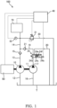
- the working fluid supply system according to the first embodiment of the present invention 100 will be described with reference to FIG. 1 .
- a working fluid supply system 100 is a system for supplying working fluid to a fluid apparatus that is operated with the working fluid.
- the working fluid supply system 100 is mounted on a vehicle provided with an engine 50 and an automatic transmission 70 that transmits output from the engine 50 to a driving wheel and the working fluid supply system 100 supplies the working fluid to the automatic transmission 70 serving as the fluid apparatus having a belt type continuously variable transmission (CVT).
- FIG. 1 is a schematic view showing the configuration of the working fluid supply system 100.
- the working fluid supply system 100 is provided with: a first oil pump 10 serving as a first pump that is driven by the output from the engine 50 serving as a driving source and that is capable of supplying working oil serving as the working fluid to the automatic transmission 70; a second oil pump 11 serving as a second pump that is, together with the first oil pump 10, driven by the output from the engine 50 and that is capable of supplying the working oil to the automatic transmission 70; a switching valve 24 serving as a valve device that is capable of switching supply targets of the working oil from the second oil pump 11; and a controller 40 serving as a control unit that controls operation of the switching valve 24 to control the supply of the working oil to the automatic transmission 70.
- the first oil pump 10 is a vane pump that is rotationally driven by the engine 50, and the first oil pump 10 sucks the working oil stored in a tank T through a first suction passage 12 and discharges the working oil to the automatic transmission 70 through a first discharge passage 13. Via a check valve 15, which allows only a flow of the working oil from the first oil pump 10 to the automatic transmission 70, the first discharge passage 13 is connected to a supply passage 14 through which the working oil to be supplied to the automatic transmission 70 flows.
- the second oil pump 11 is the vane pump that is rotationally driven by the engine 50, and the second oil pump 11 sucks the working oil stored in the tank T through a second suction passage 16 and discharges the working oil through a second discharge passage 17 serving as a discharge passage.
- the second discharge passage 17 is connected to a connecting passage 19 and a first drain passage 20 via the switching valve 24.
- the connecting passage 19 is connected to the supply passage 14 via a check valve 21 that allows only the flow of the working oil from the second oil pump 11 to the automatic transmission 70.
- a second end of the first drain passage 20, whose a first end is connected to the switching valve 24, is connected to the tank T.
- the first oil pump 10 and the second oil pump 11 may be two vane pumps configured separately or may be configured as a single vane pump such as a balanced vane pump having two suction regions and two discharge regions.
- a discharge flow amount from the first oil pump 10 and a discharge flow amount from the second oil pump 11 may be the same or different.
- the switching valve 24 is an electrically driven proportional solenoid valve, and the switching valve 24 displaces a position of a spool (not shown) to cause a port to which the second discharge passage 17 is connected to communicate with at least one port of a port to which the supply passage 14 is connected via the connecting passage 19 and a port to which the first drain passage 20, serving as another passage different from the supply passage 14, is connected.
- the another passage different from the supply passage 14 is not limited to the first drain passage 20, and it may include, for example, a passage, which is different from the supply passage 14, through which the working oil to be supplied to the automatic transmission 70 flows and a passage through which the working oil to be supplied to a fluid apparatus different from the automatic transmission 70 flows.
- the switching valve 24 has three positions, i.e. a first position 24a at which the second discharge passage 17 is communicated with the supply passage 14 through the connecting passage 19; a second position 24b at which the second discharge passage 17 is communicated with the first drain passage 20; and a third position 24c, between the first position 24a and the second position 24b, at which the second discharge passage 17 is communicated with the supply passage 14 through a first restrictor 24e and the second discharge passage 17 is communicated with the first drain passage 20 through a second restrictor 24f.
- the position of the switching valve 24 is controlled by the controller 40, in order to enable the supply of the working oil from the second oil pump 11 even when the switching valve 24 is failed, it is biased so as to be set at the first position 24a when electric current is not supplied.
- FIG. 2 is a diagram schematically showing how the respective sizes of the cross-sectional areas of a first communicating passage and a second communicating passage are changed in accordance with the position of the switching valve 24 in a case in which, in the switching valve 24, the passage through which the second discharge passage 17 and the connecting passage 19 are communicated is set as the first communicating passage and the passage through which the second discharge passage 17 and the first drain passage 20 are communicated is set as the second communicating passage.
- the cross-sectional area of the first communicating passage is set so as to be the largest at the first position 24a.
- the cross-sectional area is set so as to be gradually reduced as the position is shifted from the first position 24a towards the second position 24b and so as to become zero at the second position 24b, in other words, it is set such that the first communicating passage is closed at the second position 24b.
- the cross-sectional area of the second communicating passage is the largest at the second position 24b.
- the cross-sectional area is gradually reduced as the position is shifted from the second position 24b to the first position 24a and becomes zero at the first position 24a, in other words, it is set such that the second communicating passage is closed at the first position 24a.
- the second discharge passage 17 is communicated with the connecting passage 19 through the first communicating passage, the cross-sectional area of which has become relatively small, in other words, through the first restrictor 24e, and the second discharge passage 17 is communicated with the first drain passage 20 through the second communicating passage, the cross-sectional area of which has become relatively small, in other words, through the second restrictor 24f.
- the cross-sectional area of the first communicating passage is set so as to be the same as the cross-sectional area of the second communicating passage at the third position 24c, most of the working oil that has been discharged from the second oil pump 11 is caused to flow into the first drain passage 20.
- a flow amount of the working oil flowing into the first drain passage 20 is prevented from becoming excessively larger than the flow amount of the working oil flowing into the supply passage 14 at the third position 24c.
- the cross-sectional area of the first restrictor 24e and the cross-sectional area of the second restrictor 24f be set such that the flow amount of the working oil flowing into the first drain passage 20 becomes substantially the same as the flow amount of the working oil flowing into the supply passage 14.
- the first the cross-sectional area A1 and the second the cross-sectional area A2 may be set to the same size.
- the second oil pump 11 is shifted to a no-load operation state, in other words, the second oil pump 11 is shifted to a state in which the load for driving the second oil pump 11 is scarcely applied to the engine 50.
- the second oil pump 11 be set to the no-load operation state when the discharge of the working oil from the second oil pump 11 is not required.
- a third communication state in which the second discharge passage 17 is communicated with the connecting passage 19, and the second discharge passage 17 is communicated with the first drain passage 20 is established.
- the working oil that has been discharged from the second oil pump 11 is supplied to the automatic transmission 70 through the connecting passage 19 and the supply passage 14 and is discharged to the tank T through the first drain passage 20.
- the ratio between the flow amount of the working oil flowing into the supply passage 14 and the flow amount of the working oil flowing into the first drain passage 20 is changed in accordance with the ratio between the cross-sectional area of the first communicating passage and the cross-sectional area of the second communicating passage, the pressure in the supply passage 14, and the pressure in the first drain passage 20. Because the check valve 21 is provided between the connecting passage 19 and the supply passage 14 as described above, flow out of the working oil in the supply passage 14 to the first drain passage 20 through the connecting passage 19 and the switching valve 24 is avoided.
- the working fluid supply system 100 it is possible to supply the working oil to the automatic transmission 70 also from the second oil pump 11 in addition to the first oil pump 10 if required.
- the position of the switching valve 24 may be switched as the spool (not shown) is directly driven by a solenoid (not shown) or may be switched by the presence/absence and the level of the pilot pressure acting on the spool, and as a driving system of the switching valve 24, any system may be employed as long as the positions are switched in accordance with instructions from the controller 40.
- the working fluid supply system 100 is further provided with a pressure control valve 31 that controls the pressure of the working oil to be supplied to the automatic transmission 70.
- the pressure control valve 31 is an electromagnetic regulator appropriately discharges the working oil in the supply passage 14 to the tank T through a second drain passage 30 connected to the tank T, and the operation of the pressure control valve 31 is controlled by the controller 40 such that the pressure detected by a pressure sensor 32 capable of detecting the pressure in the supply passage 14 becomes the level set in advance.
- the level of the pressure of the working oil to be supplied to the automatic transmission 70 from the first oil pump 10 and the second oil pump 11 is always controlled so as to become a suitable level by the pressure control valve 31.
- FIG. 3 is a block diagram for explaining functions of the controller 40.
- the controller 40 is formed of a microcomputer provided with a CPU (a central processing unit), a ROM (a read only memory), a RAM (a random access memory), and an I/O interface (an input/output interface).
- the RAM stores data for processing executed by the CPU
- the ROM pre-stores a control program, etc. for the CPU
- the I/O interface is used for input/output of information to/from devices connected to the controller 40.
- the controller 40 may also be formed of a plurality of microcomputers.
- the controller 40 controls the supply state of the working oil to the automatic transmission 70 by controlling the switching of the position of the switching valve 24 on the basis of the signals indicating the state of the vehicle input from the various sensors that are provided at respective parts of the vehicle.
- the controller 40 may be configured so as to serve as both of a controller of the engine 50 and a controller of the automatic transmission 70, or it may be provided separately from the controller of the engine 50 and the controller of the automatic transmission 70.
- the signals indicating the state of the vehicle to be input to the controller 40 include: for example, the signals indicating the speed of the vehicle; the signals indicating acceleration of the vehicle; the signals indicating the operating position of a shift lever; the signals indicating the operated amount of the accelerator; the signals indicating the rotation speed of the engine 50; the signals indicating the load of the engine 50 such as the throttle position, the fuel-injection amount, and so forth; the signals indicating the input shaft and output shaft rotation speeds of the automatic transmission 70; the signals indicating the oil temperature of the working oil in the automatic transmission 70; the signals indicating the pressure of the working oil (line pressure) supplied to the automatic transmission 70; the signals indicating the transmission gear ratio of the automatic transmission 70; the signals indicating the discharge pressure of the first oil pump 10; the signals indicating the discharge pressure of the second oil pump 11; and so forth.
- the controller 40 has, as the functions for controlling the supply of the working oil to the automatic transmission 70: a required flow amount computing unit 41 that computes a required flow amount Qr of the working oil required by the automatic transmission 70 on the basis of the signals that are input from the various sensors; a discharge flow amount calculating unit 42 that calculates a first discharge flow amount Q1 of the working oil discharged from the first oil pump 10 and a second discharge flow amount Q2 of the working oil discharged from the second oil pump 11 on the basis of the signals that are input from the various sensors; a comparing unit 43 that performs comparison of the flow amount computed by the required flow amount computing unit 41 and the flow amount calculated by the discharge flow amount calculating unit 42; a supply state setting unit 45 that sets the supply state of the working oil to the automatic transmission 70 on the basis of a comparison result obtained by the comparing unit 43; and a switching control unit 46 that controls the switching of the position of the switching valve 24 in accordance with the instructions from the supply state setting unit 45.
- the required flow amount computing unit 41, etc. are shown
- the required flow amount computing unit 41 computes the flow amount of the working oil required by the automatic transmission 70 mainly on the basis of: an accelerator opening degree and a vehicle speed; the oil temperature of the working oil in the automatic transmission 70; the pressure of the working oil supplied to the automatic transmission 70; the input shaft and output shaft rotation speed of the automatic transmission 70; and the transmission gear ratio of the automatic transmission 70.
- the flow amount of the working oil required by the automatic transmission 70 includes: a transmission flow amount required for changing a width between pulleys of a variator of the belt type continuously variable transmission (not shown); a leakage flow amount through a gap in a hydraulic control valve and a gap in a hydraulic circuit; a lubrication flow amount required for cooling or lubricating the automatic transmission 70; a cooling flow amount guided to an oil cooler (not shown); and so forth.
- each of these flow amounts is mapped in advance and is stored in the ROM of the controller 40.
- the transmission flow amount takes a larger value when the transmission gear ratio is changed largely, for example, at the time of acceleration at which a rate of increase of the accelerator opening degree is large and at the time of deceleration at which a rate of deceleration of the vehicle speed is large, and therefore, a rate of change of the accelerator opening degree and of the vehicle speed are used as the parameters.
- the parameters related to the acceleration/deceleration of the vehicle the throttle position, the fuel-injection amount, and so forth affecting the change in the rotation speed and the load of the engine 50 may also be used.
- the lubrication flow amount for example, the temperature of the working oil and the rotation speed of the input/output shaft of the automatic transmission 70 are used as the parameters.
- the temperature of the working oil needs to be kept so as not to exceed a predetermined temperature, and in addition, in order to cool the working oil, it is required to achieve a state in which cooling air is guided to the oil cooler, in other words, a state in which the vehicle is traveling at a predetermined vehicle speed or higher. Therefore, for the cooling flow amount, the temperature of the working oil and the vehicle speed are mainly used as the parameters.
- the required flow amount computing unit 41 computes the required flow amount Qr that is an amount of the working oil required by the automatic transmission 70 per unit time by taking the transmission flow amount, the leakage flow amount, the lubrication flow amount, and the cooling flow amount into consideration.
- the discharge flow amount calculating unit 42 calculates the first discharge flow amount Q1 that is the amount of the working oil discharged from the first oil pump 10 per unit time mainly on the basis of the rotation speed of the engine 50 and a preset first base discharged amount D1 that is the theoretical discharged amount per revolution of the first oil pump 10.
- the discharge flow amount calculating unit 42 also calculates the second discharge flow amount Q2 that is the amount of the working oil discharged from the second oil pump 11 per unit time mainly on the basis of the rotation speed of the engine 50 and a preset second base discharged amount D2 that is the theoretical discharged amount per revolution of the second oil pump 11.
- the rotation speed of the first oil pump 10 and the first discharge flow amount Q1 of the first oil pump 10 are in a relationship in which they are changed substantially proportional to each other, and in addition, the first discharge flow amount Q1 of the first oil pump 10 is changed in response to the viscosity that varies with the oil temperature and the discharge pressure of the first oil pump 10. These relationships are mapped in advance in order to accurately calculate the first discharge flow amount Q 1 of the first oil pump 10 and are stored in the ROM of the controller 40.
- the discharge flow amount calculating unit 42 easily calculates the first discharge flow amount Q1 from the rotation speed of the engine 50, the oil temperature of the working oil, and the discharge pressure of the first oil pump 10.
- the first discharge flow amount Q 1 may be calculated by using the rotation speed of the first oil pump 10 instead of the rotation speed of the engine 50.
- the line pressure may also be used instead of the discharge pressure of the first oil pump 10 for the calculation of the first discharge flow amount Q1 of the first oil pump 10.
- the second discharge flow amount Q2 of the second oil pump 11 is also calculated in a similar manner to the first discharge flow amount Q1 of the first oil pump 10.
- the calculation of the second discharge flow amount Q2 of the second oil pump 11 is performed regardless of the switched state of the switching valve 24, in other words, regardless of whether or not the second oil pump 11 is in the state in which it supplies the working oil to the automatic transmission 70.
- the comparing unit 43 performs the comparison of the required flow amount Qr computed by the required flow amount computing unit 41 with the first discharge flow amount Q1 calculated by the discharge flow amount calculating unit 42 and the comparison of the total flow amount of the first discharge flow amount Q 1 and the second discharge flow amount Q2 with the required flow amount Qr, and sends the signals corresponding to these comparison results to the supply state setting unit 45.
- the supply state setting unit 45 sets the supply state of the working oil to the automatic transmission 70 on the basis of the signals sent from the comparing unit 43 and sends the signals to the switching control unit 46 such that thus-set supply state is achieved. Specifically, the supply state setting unit 45 sets the supply state for supplying the working oil to the automatic transmission 70 from two states: a first supply state in which the position of the switching valve 24 is switched to the second position 24b by the switching control unit 46, the working oil is not supplied to the automatic transmission 70 from the second oil pump 11, and the working oil is supplied to the automatic transmission 70 only from the first oil pump 10; and a second supply state in which the position of the switching valve 24 is switched to the first position 24a by the switching control unit 46, and the working oil is supplied to the automatic transmission 70 from two pumps: the first oil pump 10 and the second oil pump 11.
- the controller 40 further has: a pressure variation prediction unit 47 that predicts variation of the pressure that will be caused in the supply passage 14 when the position of the switching valve 24 is switched instantaneously; and a switching time setting unit 48 that sets a switching time to be spent for switching the position of the switching valve 24 in accordance with the variation of pressure predicted by the pressure variation prediction unit 47.
- the pressure variation prediction unit 47 predicts the variation of the pressure that will be caused in the supply passage 14 by using the map stored in advance on the basis of the first discharge flow amount Q1 of the working oil discharged from the first oil pump 10 and the second discharge flow amount Q2 of the working oil discharged from the second oil pump 11 both calculated by the discharge flow amount calculating unit 42.
- the pressure in the supply passage 14 the first discharge flow amount Q1, the second discharge flow amount Q2, the engine rotation speed, the temperature of the working oil before the switching valve 24 is switched; the speed and the time spent for switching the switching valve 24; and so forth are used as the parameters, for example, and the predictions are made on how the variation of the pressure caused in the supply passage 14 will be changed when these parameters are changed, and this map is stored in the ROM of the controller 40.
- arithmetic expressions for computing the pressure variation by using these as the parameters may be stored instead of the map.
- the variation of the pressure caused in the supply passage 14 when a state in which the flow amount of the working oil flowing through the supply passage 14 is the first discharge flow amount Q1 is changed to a state in which the second discharge flow amount Q2 is added thereto is predicted, and the variation of the pressure caused in the supply passage 14 when a state in which the flow amount of the working oil flowing through the supply passage 14 is the flow amount obtained by adding the first discharge flow amount Q1 and the second discharge flow amount Q2 is changed to a state in which the second discharge flow amount Q2 is subtracted therefrom is predicted.
- the larger the second discharge flow amount Q2 is, in other words, the higher the rotation speed of the engine 50 driving the second oil pump 11 is, the higher the predicted pressure variation becomes.
- the switching time setting unit 48 sets the switching time for switching the position of the switching valve 24 from the first position 24a to the second position 24b or from the second position 24b to the first position 24a in accordance with the pressure variation predicted by the pressure variation prediction unit 47 as described above. Specifically, the switching time is set at a standard switching time in a case in which the pressure variation predicted by the pressure variation prediction unit 47 is so small that the operation of the automatic transmission 70 is not affected, and the switching time is set at the time obtained by adding a predetermined additional time to the standard switching time, in other words, the time longer than the standard switching time in a case in which the pressure variation predicted by the pressure variation prediction unit 47 is so large that the operation of the automatic transmission 70 is affected.
- a duration of the standard switching time is, for example, from 0.03 seconds to 0.07 seconds, and preferably, about 0.05 seconds.
- the above-described switching control unit 46 then switches the position of the switching valve 24, via the third position 24c, from the first position 24a to the second position 24b or from the second position 24b to the first position 24a over the switching time that is set by the switching time setting unit 48.
- the time spent for the shift of the position of the switching valve 24 to the position between the first position 24a and the second position 24b including the third position 24c in other words, the time spent to achieve the third communication state becomes longer.
- the flow amount of the working oil supplied from the second oil pump 11 to the supply passage 14 is gradually reduced while the amount of the working oil discharged to the tank T through the first drain passage 20 is gradually increased.
- the sudden decrease in the flow amount of the working oil flowing through the supply passage 14 is avoided.
- the sudden decrease in the supply pressure of the working oil supplied to the automatic transmission 70 is also avoided, and as a result, it becomes possible to operate the automatic transmission 70 stably.
- step S11 as detection signals from the various sensors indicating the state of the vehicle, especially, the states of the engine 50 and the automatic transmission 70, for example, the signals indicating the speed of the vehicle, the signals indicating the acceleration of the vehicle, the signals indicating the operating position of the shift lever, the signals indicating the operated amount of the accelerator, the signals indicating the rotation speed of the engine 50, the signals indicating the load of the engine 50 such as the throttle position, the fuel-injection amount, and so forth, the signals indicating the input shaft and output shaft rotation speeds of the automatic transmission 70, the signals indicating the oil temperature of the working oil in the automatic transmission 70, the signals indicating the pressure of the working oil (the line pressure) supplied to the automatic transmission 70, the signals indicating the transmission gear ratio of the automatic transmission 70, the signals indicating the discharge pressure of the first oil pump 10, the signals indicating the discharge pressure of the second oil pump 11, and so forth are input to the controller 40.
- the signals indicating the speed of the vehicle for example, the signals indicating the acceleration of the vehicle, the signals indicating the operating
- step S12 on the basis of the signals from the various sensors that are input in step S11, the required flow amount Qr of the working oil that is required by the automatic transmission 70 is computed by the required flow amount computing unit 41.
- step S13 on the basis of the signals from the various sensors that are input in step S11, the first discharge flow amount Q 1 of the working oil discharged from the first oil pump 10 and the second discharge flow amount Q2 of the working oil discharged from the second oil pump 11 are calculated by the discharge flow amount calculating unit 42.
- the specification of the first oil pump 10 and the specification of the second oil pump 11 are identical to each other, and the first discharge flow amount Q 1 and the second discharge flow amount Q2 are the same value, it suffices to calculate either one of them.
- the required flow amount Qr that is computed in step S12 and the first discharge flow amount Q1 that is calculated in step S13 are compared by the comparing unit 43 in step S14.
- step S14 when it is determined that the first discharge flow amount Q1 is equal to or higher than the required flow amount Qr, in other words, when it is possible to cover the required flow amount Qr of the working oil that is required by the automatic transmission 70 only by the first oil pump 10, the process proceeds to step S15.
- step S15 the supply state of the working oil to the automatic transmission 70 is set to the first supply state by the supply state setting unit 45.
- the required flow amount Qr of the working oil that is required by the automatic transmission 70 is relatively low, it is possible to cover the required flow amount Qr only by driving the first oil pump 10.
- such a situation includes: a case in which the vehicle is in the steady travelling state at which a sudden acceleration and a sudden deceleration are not performed and in which there is almost no increase/decrease in the transmission flow amount; a case in which the leakage flow amount is relatively low because the oil temperature of the working oil is at or lower than 120 °C, for example; a case in which the cooling flow amount is not required to be ensured because the oil temperature of the working oil is low to medium temperature; and so forth.
- step S14 when it is determined that the first discharge flow amount Q1 is lower than the required flow amount Qr, in other words, when the required flow amount Qr of the working oil that is required by the automatic transmission 70 cannot be covered only by the first oil pump 10, the process proceeds to step S16.
- step S16 the supply state of the working oil to the automatic transmission 70 is set to the second supply state by the supply state setting unit 45.
- the required flow amount Qr of the working oil that is required in the automatic transmission 70 is relatively high, the required flow amount Qr is covered by driving the second oil pump 11 in addition to the first oil pump 10.
- such a situation includes: a case in which the transmission flow amount is increased at the state of travelling with acceleration/deceleration; a case in which the leakage flow amount is relatively high because the oil temperature of the working oil is exceeding 120 °C, for example; a case in which the oil temperature of the working oil is high and the cooling flow amount needs to be ensured; and so forth.
- step S17 it is determined whether or not the supply state needs to be changed, in other words, whether or not the supply state determined in steps S14 to S16 described above is the same as the supply state currently set.
- step S18 in a case in which the setting has been changed to the second supply state when the current supply state is the first supply state and in a case in which the setting has been changed to the first supply state when the current supply state is the second supply state, it is determined that the supply state needs to be changed, and the process proceeds to step S18.
- step S18 the pressure variation prediction unit 47 predicts the variation of the pressure caused in the supply passage 14, on the basis of the first discharge flow amount Q1 of the working oil discharged from the first oil pump 10 and the second discharge flow amount Q2 of the working oil discharged from the second oil pump 11 calculated by the discharge flow amount calculating unit 42, by using the map in which, for example, the pressure in the supply passage 14, the first discharge flow amount Q1, the second discharge flow amount Q2, the engine rotation speed, the temperature of the working oil before the switching valve 24 is switched, the speed or the time spent for switching the switching valve 24, and so forth are used as the parameters, and how the pressure variation caused in the supply passage 14 will be changed when these parameters are changed is predicted.
- the switching time setting unit 48 sets the switching time for switching the position of the switching valve 24 from the first position 24a to the second position 24b or from the second position 24b to the first position 24a.
- step S19 When the switching time is set by the switching time setting unit 48 in step S19, in following step S20, the position of the switching valve 24 is switched by the switching control unit 46 by spending the set switching time.
- the switching time is set to the relatively short standard switching time of about 0.03 seconds to 0.07 seconds, for example. Therefore, in a case in which the pressure variation is predicted to be small, the switching of the position of the switching valve 24 is performed at a relatively early stage, and the flow amount of the working oil flowing through the supply passage 14 is increased and/or decreased quickly. In other words, the flow amount of the working oil flowing through the supply passage 14 quickly becomes the flow amount that is sufficient to cover the required flow amount Qr of the working oil required by the automatic transmission 70.
- the communication state achieved by the switching valve 24 is switched from the first communication state to the second communication state or from the second communication state to the first communication state via the third communication state by spending the switching time that is set in accordance with the degree of the pressure variation predicted to be caused in the supply passage 14 when the communication state achieved by the switching valve 24 is switched instantaneously.
- the flow amount of the working oil flowing through the supply passage 14 is increased and/or decreased quickly and becomes the flow amount that is sufficient to cover the required flow amount Qr of the working oil required by the automatic transmission 70. Therefore, it is possible to continuously operate the automatic transmission 70 in a stable manner by shortening the switching time when the predicted pressure variation is small, and by shortening the time period during which the second oil pump 11 is wastefully driven, it is possible to improve the efficiency of the working fluid supply system 100 as a whole.
- Basic configurations of the working fluid supply system 200 are the same as those of the working fluid supply system 100 according to the first embodiment.
- the working fluid supply system 200 differs from the working fluid supply system 100 in that a first switching valve 124, a second switching valve 125, and a third switching valve 126 are provided as the valve devices instead of the switching valve 24.
- the first switching valve 124 that is connected to the second oil pump 11 via the second discharge passage 17 is a three-port two-position electromagnetic switching valve having a first position 124a at which the port to which the second discharge passage 17 is connected is communicated with a port to which a first connecting passage 18a is connected and a second position 124b at which the port to which the second discharge passage 17 is connected is communicated with a port to which a first drain connecting passage 20a is connected.
- a second end of the first connecting passage 18a, a first end of which is connected to the first switching valve 124, is connected to the second switching valve 125, and a second end of the first drain connecting passage 20a, a first end of which is connected to the first switching valve 124, is connected to the first drain passage 20.
- the second switching valve 125 that is connected to the first switching valve 124 via the first connecting passage 18a is the three-port two-position electromagnetic switching valve having a first position 125a at which a port to which the first connecting passage 18a is connected is communicated with a port to which a second connecting passage 18b is connected and a second position 125b at which a port to which the first connecting passage 18a is connected is communicated with a port to which the second connecting passage 18b is connected and a port to which the first connecting passage 18a is connected is communicated via a restrictor 125c with a port to which a second drain connecting passage 20b is connected.
- the third switching valve 126 that is connected to the second switching valve 125 via the second connecting passage 18b is the three-port two-position electromagnetic switching valve having a first position 126a at which a port to which the second connecting passage 18b is connected is communicated with a port to which the connecting passage 19 is connected and a second position 126b at which a port to which the second connecting passage 18b is connected is communicated with a port to which the connecting passage 19 is connected and a port to which the second connecting passage 18b is connected is communicated via a restrictor 126c with a port to which a third drain connecting passage 20c is connected.
- a second end of the third drain connecting passage 20c, a first end of which is connected to the third switching valve 126, is connected to the first drain passage 20.
- the positions of these switching valves 124, 125, and 126 are controlled by the controller 40, in order to enable the supply of the working oil from the second oil pump 11 even when the switching valves 124, 125, and 126 are failed, they are biased so as to be respectively set at the first positions 124a, 125a, and 126a when electric current is not supplied.
- the first drain passage 20 that is connected to the respective switching valves 124, 125, and 126 via the drain connecting passages 20a, 20b, and 20c corresponds to the another passage different from the supply passage 14.
- FIG. 6 is a diagram schematically showing how the respective sizes of the cross-sectional areas of the first communicating passage and the second communicating passage are changed in accordance with the position of each of the switching valves 124, 125, and 126.
- the cross-sectional area of the first communicating passage is set so as to be the largest when the position of the first switching valve 124 is set at the first position 124a and so as to be zero when the position of the first switching valve 124 is set at the second position 124b, in other words, the cross-sectional area is set such that the first communicating passage is closed when the position of the first switching valve 124 is set at the second position 124b.
- the cross-sectional area of the second communicating passage is set so as to be the largest when the position of the first switching valve 124 is set at the second position 124b.
- the cross-sectional area is set so as to be gradually reduced when the position of the first switching valve 124 is set at the first position 124a and the positions of the second switching valve 125 and the third switching valve 126 are set at the second positions 125b and 126b and when the positions of the first switching valve 124 and the second switching valve 125 are set at the first positions 124a and 125a and the position of the third switching valve 126 is set at the second position 126b.
- the second discharge passage 17 is communicated with the connecting passage 19 through the first communicating passage having a relatively large cross-sectional area
- the second discharge passage 17 is communicated with the first drain passage 20 through the second communicating passage having a cross-sectional area that is smaller relative to that of the first communicating passage.
- the position of the first switching valve 124 is set at the first position 124a and the positions of the second switching valve 125 and the third switching valve 126 are set at the second positions 125b and 126b, and when the positions of the first switching valve 124 and the second switching valve 125 are set at the first positions 124a and 125a and the position of the third switching valve 126 is set at the second position 126b, the flow amount of the working oil flowing into the first drain passage 20 is prevented from becoming larger than the flow amount of the working oil flowing into the supply passage 14.
- the restrictors be respectively provided at a portion through which the first connecting passage 18a is communicated with the second connecting passage 18b at the second position 125b of the second switching valve 125 and at a portion through which the second connecting passage 18b is communicated with the connecting passage 19 at the second position 126b of the third switching valve 126, such that the flow amount of the working oil flowing into the supply passage 14 and the flow amount of the working oil flowing into the another passage different from the supply passage 14 become the same by symmetrically increasing or decreasing the cross-sectional area of the first communicating passage and the cross-sectional area of the second communicating passage.
- the position of the first switching valve 124 having the above-described configuration is switched to the first position 124a, the position of the second switching valve 125 is switched to the first position 125a, and the position of the third switching valve 126 is switched to the first position 126a, the first communication state in which the second discharge passage 17 is communicated with the connecting passage 19, and the communication between the second discharge passage 17 and the first drain passage 20 is shut off is established.
- the working oil that has been discharged from the second oil pump 11 is supplied to the automatic transmission 70 through the connecting passage 19 and the supply passage 14.
- the second communication state in which the second discharge passage 17 is communicated with the first drain passage 20 and the communication between the second discharge passage 17 and the connecting passage 19 is shut off is established.
- the working oil that has been discharged from the second oil pump 11 is discharged to the tank T through the first drain passage 20.
- the second oil pump 11 is shifted to the no-load operation state, in other words, the second oil pump 11 is shifted to the state in which the load for driving the second oil pump 11 is scarcely applied to the engine 50.
- the second oil pump 11 be set to the no-load operation state when the discharge of the working oil from the second oil pump 11 is not required.
- the third communication state in which the second discharge passage 17 is communicated with the connecting passage 19 and the second discharge passage 17 is communicated with the first drain passage 20 is established.
- the working oil that has been discharged from the second oil pump 11 is supplied to the automatic transmission 70 through the connecting passage 19 and the supply passage 14 and is discharged to the tank T through the first drain passage 20.
- the ratio between the flow amount of the working oil flowing into the supply passage 14 and the flow amount of the working oil flowing into the first drain passage 20 is changed in accordance with the ratio between the cross-sectional area of the first communicating passage and the cross-sectional area of the second communicating passage, the pressure in the supply passage 14, or the pressure in the first drain passage 20. Because the check valve 21 is provided between the connecting passage 19 and the supply passage 14 as described above, the flow out of the working oil in the supply passage 14 to the first drain passage 20 through the second switching valve 125 and the third switching valve 126 is avoided.
- each of the switching valves 124, 125, and 126 may be switched as a valve body (not shown) is directly driven by the solenoid (not shown) or may be switched by the presence/absence or the level of the pilot pressure acting on the valve body, and as a driving system of each of the switching valves 124, 125, and 126, any system may be employed as long as the positions are switched in accordance with instructions from the controller 40.
- the controller 40 further has: the pressure variation prediction unit 47 that predicts the variation of the pressure that will be caused in the supply passage 14 in a case in which the first communication state is switched instantaneously to the second communication state or in a case in which the second communication state is switched instantaneously to the first communication state; and the switching time setting unit 48 that sets the switching time to be spent for switching the first communication state to the second communication state or the second communication state to the first communication state in accordance with the variation of pressure predicted by the pressure variation prediction unit 47.
- the pressure variation prediction unit 47 is a part that has the similar functions with those of the pressure variation prediction unit 47 in the above-described first embodiment, the description thereof will be omitted.
- the positions of the three switching valves 124, 125, and 126 need to be switched as described above.
- the time spent until the switching of the three switching valves 124, 125, and 126 is completed corresponds to the switching time that is spent for the switching of the first communication state to the second communication state or the second communication state to the first communication state via the third communication state.
- the switching time setting unit 48 sets time intervals for switching the respective switching valves 124, 125, and 126 as the switching time.
- the switching time interval between the switching of the position of the third switching valve 126 from the first position 126a to the second position 126b and the switching of the position of the second switching valve 125 from the first position 125a to the second position 125b and the switching time interval between the switching of the position of the second switching valve 125 from the first position 125a to the second position 125b and the switching of the position of the first switching valve 124 from the first position 124a to the second position 124b are set as the switching time to be spent for switching from the first communication state to the second communication state via the third communication state.
- the switching time interval between the switching of the position of the first switching valve 124 from the second position 124b to the first position 124a and the switching of the position of the second switching valve 125 from the second position 125b to the first position 125a and the switching time interval between the switching of the position of the second switching valve 125 from the second position 125b to the first position 125a and the switching of the position of the third switching valve 126 from the second position 126b to the first position 126a are set as the switching time to be spent for switching the second communication state to the first communication state via the third communication state.
- Each of the switching time intervals is set to the standard time interval in a case in which the pressure variation predicted by the pressure variation prediction unit 47 is so small that the operation of the automatic transmission 70 is not affected, and each of the switching time intervals is set to the switching time interval obtained by adding the predetermined additional time interval to the standard time interval, in other words, the switching time interval that is longer than the standard time interval in a case in which the pressure variation predicted by the pressure variation prediction unit 47 is so large that the operation of the automatic transmission 70 is affected.
- the duration of the standard time interval is, for example, from 0.03 seconds to 0.07 seconds, and preferably about 0.05 seconds.
- the predetermined additional time interval should be in relation to the pressure variation is determined in advance by experiments, etc. and the obtained results are mapped, and they are stored in the ROM of the controller 40 together with the standard time interval.
- the pressure of the working oil acting on the valve body of each of the switching valves 124, 125, and 126, etc. may be taken into consideration, and arithmetic expressions for computing the predetermined additional time interval by using these as the parameters may be stored in the ROM of the controller 40.
- the switching control unit 46 controls the switching of the respective switching valves 124, 125, and 126 such that, for example, the switching time interval, which is obtained by adding the switching time interval between the switching of the position of the first switching valve 124 and the switching of the position of the second switching valve 125, to the switching time interval between the switching of the position of the second switching valve 125 and the switching of the position of the third switching valve 126, becomes the switching time interval that is set by the switching time setting unit 48.
- the switching time setting unit 48 may, for example, set the switching time interval between the switching of the position of the first switching valve 124 and the switching of the position of the second switching valve 125 separately from the switching time interval between the switching of the position of the second switching valve 125 and the switching of the position of the third switching valve 126, and in this case, the switching control unit 46 controls the switching of the respective switching valves 124, 125, and 126 such that the respective switching time intervals becomes the switching time interval that is set by the switching time setting unit 48.
- the longer the switching time interval is set.
- the longer the switching time interval is set, the longer the time maintained in the state in which the position of the first switching valve 124 is set at the first position 24a, and at least one of the positions of the second switching valve 125 and the third switching valve 126 is set at the second positions 125b and 126b becomes, in other words, the longer the time maintained in the third communication state becomes.
- the flow amount of the working oil supplied from the second oil pump 11 to the supply passage 14 is gradually reduced while the amount of the working oil discharged to the tank T through the first drain passage 20 is gradually increased.
- the sudden decrease in the flow amount of the working oil flowing through the supply passage 14 is avoided.
- the sudden decrease in the supply pressure of the working oil supplied to the automatic transmission 70 is also avoided, and as a result, it becomes possible to operate the automatic transmission 70 stably.
- the flow amount of the working oil discharged to the tank T through the first drain passage 20 is gradually reduced while the flow amount of the working oil supplied from the second oil pump 11 to the supply passage 14 is gradually increased.
- the sudden increase in the flow amount of the working oil flowing through the supply passage 14 is avoided.
- the sudden increase in the supply pressure of the working oil supplied to the automatic transmission 70 is also avoided, and as a result, it becomes possible to operate the automatic transmission 70 stably.
- control performed by the controller 40 which has the above-described functions, at the time when the working oil is supplied to the automatic transmission 70 will be described with reference to the flow chart shown in FIG. 7 .
- the control shown in FIG. 7 is executed repeatedly by the controller 40 at every predetermined time periods.
- step S11 to step S18 in FIG. 7 are the same as the control in the above-described first embodiment shown in FIG. 4 , the description thereof will be omitted.
- step S21 following step S18 the switching time setting unit 48 sets the switching time interval for switching the first communication state to the second communication state or for switching the second communication state to the first communication state.
- step S21 when the switching time interval is set by the switching time setting unit 48, in subsequent step S22, the switching of the respective switching valves 124, 125, and 126 are controlled by the switching control unit 46.
- the switching of the respective switching valves 124, 125, and 126 is controlled such that the switching time interval, which is obtained by adding the switching time interval between the switching of the position of the third switching valve 126 and the switching of the position of the second switching valve 125 to the switching time interval between the switching of the position of the second switching valve 125 and the switching of the position of the first switching valve 124, becomes the switching time interval that is set by the switching time setting unit 48.
- the switching from the first communication state to the second communication state is performed by following procedures.
- the communication between the second discharge passage 17 and the supply passage 14 is shut off, and so, all of the working oil that has discharged from the oil pump 11 is returned to the tank T through the first drain connecting passage 20a.
- the cross-sectional area of the second communicating passage through which the second discharge passage 17 is communicated with the first drain passage 20 is increased in a stepwise manner, and thus, the communication state is switched from the first communication state to the second communication state.
- the switching of the position of the second switching valve 125 and the switching of the position of the third switching valve 126 may be performed in any order.
- the switching of the respective switching valves 124, 125, and 126 are controlled such that the switching time interval obtained by adding the switching time interval between the switching of the position of the first switching valve 124 and the switching of the position of the second switching valve 125 to the switching time interval between the switching of the position of the second switching valve 125 and the switching of the position of the third switching valve 126 becomes the switching time interval that is set by the switching time setting unit 48.
- the switching from the second communication state to the first communication state is performed by following procedures.
- the second communication state is switched to the first communication state, from the state in which the position of the first switching valve 124 is set at the second position 124b, the position of the second switching valve 125 is set at the second position 125b, and the position of the third switching valve 126 is set at the second position 126b, in other words, from the state in which all of the working oil that has been discharged from the second oil pump 11 is returned to the tank T, the position of the first switching valve 124 is switched to the first position 124a.
- the second discharge passage 17 is communicated with the supply passage 14 while the second discharge passage 17 is communicated with the tank T through the restrictor 125c and the restrictor 126c.
- the communication between the second discharge passage 17 and the tank T is shut off, and all of the working oil that has been discharged from the oil pump 11 is supplied to the supply passage 14.
- the communication state is switched from the second communication state to the first communication state.
- the switching of the position of the second switching valve 125 and the switching of the position of the third switching valve 126 may be performed in any order.
- the switching time interval is set to the relatively short standard time interval of about 0.03 seconds to 0.07 seconds, for example. Therefore, in a case in which the pressure variation is predicted to be small, the time elapsed from the switching of the position of the first switching valve 124 until the switching of the position of the third switching valve 126 is completed or the time elapsed from the switching of the position of the third switching valve 126 until the switching of the position of the first switching valve 124 is completed become relatively short, and the flow amount of the working oil flowing through the supply passage 14 is increased and/or decreased quickly. In other words, the flow amount of the working oil flowing through the supply passage 14 quickly becomes the flow amount that is sufficient to cover the required flow amount Qr of the working oil required by the automatic transmission 70.
- the communication state achieved by the switching valves 124, 125, and 126 is switched from the first communication state to the second communication state or from the second communication state to the first communication state via the third communication state by spending the switching time that is set in accordance with the degree of the pressure variation predicted to be caused in the supply passage 14 when the communication state achieved by the switching valves 124, 125, and 126 is switched instantaneously.
- the flow amount of the working oil flowing through the supply passage 14 is increased and/or decreased quickly and becomes the flow amount that is sufficient to cover the required flow amount Qr of the working oil required by the automatic transmission 70. Therefore, it is possible to continuously operate the automatic transmission 70 in a stable manner by shortening the switching time when the predicted pressure variation is small, and by shortening the time period during which the second oil pump 11 is wastefully driven, it is possible to improve the efficiency of the working fluid supply system 200 as a whole.
- the number of the switching valves to be provided on the downstream side of the first switching valve 124 is not limited thereto, and it suffices that at least one switching valve having the position that achieves the third communication state is provided on the downstream side of the first switching valve 124.
- the number of such a switching valve may be, for example, only one, or may be three or more.
- the first oil pump 10 and the second oil pump 11 are each a vane pump of a fixed displacement type.
- the first oil pump 10 and the second oil pump 11 may be each a variable displacement vane pump, a piston pump, an internal gear pump, and an external gear pump.
- the pump that supplies the working oil to the automatic transmission 70 is configured of two pumps, i.e., the first oil pump 10 and the second oil pump 11.
- the pump that supplies the working oil to the automatic transmission 70 is not limited thereto, and a plurality of oil pumps driven by the output from the engine 50 may be provided in addition to the valve devices, and oil pumps driven by the output from the electric motor may also be provided.
- the working oil is used as the working fluid
- a non-compressive fluid such as water, aqueous solution, and so forth may also be used instead of the working oil.
- the automatic transmission 70 is a transmission provided with the belt type continuously variable transmission (the CVT) has been described in the respective embodiments described above, the automatic transmission 70 may be of any type as long as it is operated by utilizing the pressure of the working oil, and the automatic transmission 70 may be provided with the toroidal continuously variable transmission or the planetary gear mechanism.
- working fluid supply systems 100 and 200 have been described as those for supplying the working fluid to the motive force transmitting device of the vehicle in the respective embodiments described above, the applications of the working fluid supply systems 100 and 200 of the present invention are not limited to the vehicles, and the working fluid supply systems 100 and 200 may also be applied to, for example, construction work equipment, ships, aircraft, and stationary equipment as long as they are provided with a fluid apparatus operated by the working fluid supplied by a pump.
- the first oil pump 10 and the second oil pump 11 are driven by the output from the engine 50.
- the driving source driving the first oil pump 10 and the second oil pump 11 is not limited to the engine 50, and for example, the driving source may be an electric motor driving the driving wheel of the vehicle.
- the various signals are listed as the signals indicating the state of the vehicle to be input to the controller 40, in a case in which the torque converter is provided in the automatic transmission 70, for example, the signals indicating the operated state and the engaged state of the torque converter may be input to the controller 40 additionally.
- the required flow amount Qr of the automatic transmission 70 may be computed or the switching of the supply state of the working oil to the automatic transmission 70 may be limited by taking the state of the torque converter into consideration. For example, when it is detected that the torque converter is in a semi-engaged state (a slip lock up state), the shifting of the working oil the supply state to other supply state may be prohibited. By doing so, it is possible to maintain the torque converter in a stable operated state.
- the signals indicating the operated amount and the operated speed of the brake may be input to the controller 40 as the signals indicating the deceleration state of the vehicle.
- the first discharge flow amount Q 1 of the working oil discharged from the first oil pump 10 and the second discharge flow amount Q2 of the working oil discharged from the second oil pump 11 are calculated.
- the actual discharge flow amount of the working oil discharged from the first oil pump 10 and the second oil pump 11 may be measured by a flow amount sensor, etc. directly.
- the working fluid supply system 100, 200 is provided with: the first oil pump 10 and the second oil pump 11 driven by the output from the engine 50, the first oil pump 10 and the second oil pump 11 being capable of supplying the working oil to the automatic transmission 70 through the supply passage 14; the valve device 24, 124, 125, 126 configured to cause the second discharge passage 17 that is the discharge passage of the second oil pump 11 to communicate with at least one of the supply passage 14 and the first drain passage 20 that is the another passage different from the supply passage 14; and the controller 40 configured to change the communication state of the valve device in accordance with the required flow amount of the working oil required by the automatic transmission 70, wherein the valve device has: the first communication state at which the second discharge passage 17 is communicated only with the supply passage 14; the second communication state at which the second discharge passage 17 is communicated only with the first drain passage 20; and the third communication state at which the second discharge passage 17 is communicated with the supply passage 14 and the first drain passage 20 while the first communication state is shifted to the second communication state or while the second communication state is shifted to
- the communication state achieved by the switching valve 24, 124, 125, 126 is switched from the first communication state to the second communication state or from the second communication state to the first communication state via the third communication state by spending the switching time that is set in accordance with the degree of the predicted pressure variation.
- the flow amount of the working oil flowing through the supply passage 14 is increased and/or decreased quickly, and the flow amount that is sufficient to cover the required flow amount Qr of the working oil required by the automatic transmission 70 is obtained. Therefore, by shortening the switching time when the predicted pressure variation is small, it is possible to continuously operate the automatic transmission 70 in a stable manner, and at the same time, by shortening the time period during which the second oil pump 11 is wastefully driven, it is possible to improve the efficiency of the working fluid supply system 100, 200 as a whole.
- the controller 40 has: the discharge flow amount calculating unit 42 configured to calculate the first discharge flow amount Q 1 of the working oil discharged from the first oil pump 10 and the second discharge flow amount Q2 of the working oil discharged from the second oil pump 11; the pressure variation prediction unit 47 configured to predict the variation of the pressure caused in the supply passage 14 on the basis of the first discharge flow amount Q1 and the second discharge flow amount Q2; and the switching time setting unit 48 configured to set the switching time in accordance with the variation of pressure predicted by the pressure variation prediction unit 47, wherein as the discharged amount of the second oil pump 11 is increased, the pressure variation is predicted to be increased, and the switching time is set so as to be longer.
- the communication state achieved by the switching valve 24, 124, 125, 126 is switched instantaneously, as the discharged amount of the second oil pump 11 is increased, the increase and/or the decrease in the flow amount of the working oil flowing through the supply passage 14 is increased, and therefore, a relatively large pressure variation tends to be caused in the supply passage 14.
- the valve device is the switching valve 24 having: the first position 24a at which the first communication state is achieved; the second position 24b at which the second communication state is achieved; and the third position 24c at which the third communication state is achieved between the first position 24a and the second position 24b, and the controller 40 is configured to switch the position of the switching valve 24 by spending the switching time such that the first communication state is switched to the second communication state or the second communication state is switched to the first communication state via the third communication state.
- the valve device is the switching valve 24 having: the first position 24a at which the first communication state is achieved; the second position 24b at which the second communication state is achieved; the third position 24c at which the third communication state is achieved between the first position 24a and the second position 24b.
- the another passage is the first drain passage 20 configured to return the working oil to the tank T, the working oil being discharged from the second oil pump 11, at the third position 24c, the cross-sectional area of the second communicating passage through which the second discharge passage 17 is communicated with the first drain passage 20 is set so as to be smaller than the cross-sectional area of the first communicating passage through which the second discharge passage 17 is communicated with the supply passage 14.
- the cross-sectional area of the second communicating passage through which the second discharge passage 17 is communicated with the first drain passage 20 is set so as to be smaller than the cross-sectional area of the first communicating passage through which the second discharge passage 17 is communicated with the supply passage 14.
- the pressure in the first drain passage 20 becomes lower relative to the pressure in the supply passage 14
- the cross-sectional area of the first communicating passage is set so as to be the same as the cross-sectional area of the second communicating passage at the third position 24c, most of the working oil that has been discharged from the second oil pump 11 flows into the first drain passage 20.
- the third position 24c by setting the cross-sectional area of the second communicating passage so as to be smaller than the cross-sectional area of the first communicating passage, the flow amount of the working oil flowing into the first drain passage 20 is restricted, and at the same time, the flow amount of the working oil flowing into the supply passage 14 is ensured, and thereby, it is possible to avoid the sudden increase and decrease in the flow amount of the working oil supplied from the second oil pump 11 to the supply passage 14 when the position is switched to the third position 24c.
- the valve device has: the first switching valve 124 having the first position 124a at which the second discharge passage 17 is communicated only with the supply passage 14 and the second position 124b at which the second discharge passage 17 is communicated only with the first drain passage 20; and the second switching valve 125 provided on the downstream side of the first switching valve 124, the second switching valve 125 having the first position 125a at which the second discharge passage 17 is communicated only with the supply passage 14 and the second position 125b at which the second discharge passage 17 is communicated with the supply passage 14 and the first drain passage 20, the first communication state is established when the first switching valve 124 is set at the first position 124a and the second switching valve 125 is set at the first position 125a, the second communication state is established when the first switching valve 124 is set at the second position 124b, and the third communication state is established when the first switching valve 124 is set at the first position 124a and the second switching valve 125 is set at the second position 125b, and the controller 40 is configured to switch the positions of the first switching valve
- the valve device is configured of two two-position switching valves, i.e., the first switching valve 124 and the second switching valve 125.
- the first switching valve 124 and the second switching valve 125 As described above, by switching the positions of the switching valves 124 and 125 by spending the switching time, it is possible to ensure the time maintained in the third communication state, in other words, a state in which the working oil that has been discharged from the second oil pump 11 can flow into the passages of both of the supply passage 14 and the first drain passage 20. By doing so, it is possible to avoid the sudden increase and decrease in the flow amount of the working oil supplied from the second oil pump 11 to the supply passage 14 when the first communication state is switched to the second communication state or when the second communication state is switched to the first communication state.
- the two-position switching valve which has a simple configuration and which is controlled easily, as the valve device, it is possible to reduce a production cost of the working fluid supply system 200.
- the another passage is the first drain passage 20 configured to return the working oil to the tank T, the working oil being discharged from the second oil pump 11, at the second position 125b of the second switching valve 125, the cross-sectional area of the second communicating passage through which the second discharge passage 17 is communicated with the first drain passage 20 is set so as to be smaller than the cross-sectional area of the first communicating passage through which the second discharge passage 17 is communicated with the supply passage 14.
- the cross-sectional area of the second communicating passage through which the second discharge passage 17 is communicated with the first drain passage 20 is set so as to be smaller than the cross-sectional area of the first communicating passage through which the second discharge passage 17 is communicated with the supply passage 14.
- the pressure in the first drain passage 20 becomes lower relative to the pressure in the supply passage 14
- the cross-sectional area of the first communicating passage is set so as to be the same as the cross-sectional area of the second communicating passage at the second position 125b of the second switching valve 125, most of the working oil that has been discharged from the second oil pump 11 flows into the first drain passage 20.
- the flow amount of the working oil flowing into the first drain passage 20 is restricted, and at the same time, the flow amount of the working oil flowing into the supply passage 14 is ensured, and thereby, it is possible to avoid the sudden increase and decrease in the flow amount of the working oil supplied from the second oil pump 11 to the supply passage 14 when the position of the second switching valve 125 is switched to the second position 125b.
- the valve device further has the third switching valve 126, the third switching valve 126 being provided on the downstream side of the second switching valve 125, the second switching valve 125 having the first position 126a at which the second discharge passage 17 is communicated only with the supply passage 14 and the second position 126b at which the second discharge passage 17 is communicated with the supply passage 14 and the first drain passage 20, the first communication state is established when the first switching valve 124 is set at the first position 124a, the second switching valve 125 is set at the first position 125a, and the third switching valve 126 is set at the first position 126a, the second communication state is established when the first switching valve 124 is set at the second position 124b, and the third communication state is established when the first switching valve 124 is set at the first position 124a, the second switching valve 125 is set at the first position 125a or the second position 125b, and the third switching valve 126 is set at the second position 126b, and the controller 40 is configured to switch the positions of the first switching valve 124, the second switching valve
- the third switching valve 126 is further provided on the downstream side of the second switching valve 125, and the third communication state is established when the second switching valve 125 is set at the second position 125b and when the third switching valve 126 is set at the second position 126b.
- the second position 125b of the second switching valve 125 and the second position 126b of the third switching valve 126 it is possible to respectively set the size of the cross-sectional area of the first communicating passage through which the second discharge passage 17 is communicated with the supply passage 14 and the size of the cross-sectional area of the second communicating passage through which the second discharge passage 17 is communicated with the first drain passage 20.
Landscapes
- Engineering & Computer Science (AREA)
- Mechanical Engineering (AREA)
- General Engineering & Computer Science (AREA)
- Physics & Mathematics (AREA)
- Fluid Mechanics (AREA)
- Control Of Transmission Device (AREA)
- Fluid-Pressure Circuits (AREA)
Description
- The present invention relates to a working fluid supply system configured to supply working fluid to a fluid apparatus.
-
US 2010/281859 A1 introduces an enhanced oil pressure system featuring two pumps controlled by the engine's rotational speed, aimed at efficiently managing high and low-pressure circuits. It describes traditional systems' inefficiencies, notably significant power loss due to high relief pressure required for oil flow regulation. The solution proposed inUS 2010/281859 A1 includes a dual-pump mechanism with a specific flow passage and relief valve design, incorporating a flow passage changeover valve to optimize oil distribution based on operational demands. -
JP 2010 014101 A -
JP H10 266978 A - In the working fluid supply system described in
JP H10 266978 A - An object of the present invention is to suppress variation of supply pressure that is caused by switching of a supply state of working fluid to a fluid apparatus in which the working fluid is supplied from at least two pumps.
- According to the present invention, a working fluid supply system configured to supply working fluid to a fluid apparatus comprises: a first pump and a second pump driven by output from a common driving source, the first pump and the second pump being capable of supplying working fluid to the fluid apparatus through a supply passage; a valve device configured to cause a discharge passage of the second pump to communicate with at least one of the supply passage and another passage different from the supply passage; and a control unit configured to change a communication state of the valve device in accordance with a required flow amount of the working fluid required by the fluid apparatus. The valve device has: a first communication state at which the discharge passage is communicated only with the supply passage; a second communication state at which the discharge passage is communicated only with the another passage; and a third communication state at which the discharge passage is communicated with the supply passage and the another passage while the first communication state is shifted to the second communication state or while the second communication state is shifted to the first communication state, and the control unit is: configured to set switching time for switching the communication state of the valve device in accordance with a degree of a pressure variation predicted to be caused in the supply passage when the communication state of the valve device is switched instantaneously from the first communication state to the second communication state or from the second communication state to the first communication state; and configured to switch the communication state of the valve device from the first communication state to the second communication state or from the second communication state to the first communication state via the third communication state by spending the set switching time.
-
-
FIG. 1 is a schematic view showing a configuration of a working fluid supply system according to a first embodiment of the present invention. -
FIG. 2 is a diagram for explaining a communication state of a switching valve of the working fluid supply system according to the first embodiment of the present invention. -
FIG. 3 is a block diagram for explaining functions of a controller of the working fluid supply system according to the first embodiment of the present invention. -
FIG. 4 is a flow chart showing a procedure of a control executed by a controller of the working fluid supply system according to the first embodiment of the present invention. -
FIG. 5 is a schematic view showing the configuration of the working fluid supply system according to a second embodiment of the present invention. -
FIG. 6 is a diagram for explaining the communication state of the switching valve of the working fluid supply system according to the second embodiment of the present invention. -
FIG. 7 is a flow chart showing a procedure of the control executed by the controller of the working fluid supply system according to the second embodiment of the present invention. - Embodiments of the present invention will be described below with reference to the attached drawings.
- The working fluid supply system according to the first embodiment of the
present invention 100 will be described with reference toFIG. 1 . - A working
fluid supply system 100 is a system for supplying working fluid to a fluid apparatus that is operated with the working fluid. In the following, description will be given of a case in which the workingfluid supply system 100 is mounted on a vehicle provided with anengine 50 and anautomatic transmission 70 that transmits output from theengine 50 to a driving wheel and the workingfluid supply system 100 supplies the working fluid to theautomatic transmission 70 serving as the fluid apparatus having a belt type continuously variable transmission (CVT).FIG. 1 is a schematic view showing the configuration of the workingfluid supply system 100. - The working
fluid supply system 100 is provided with: afirst oil pump 10 serving as a first pump that is driven by the output from theengine 50 serving as a driving source and that is capable of supplying working oil serving as the working fluid to theautomatic transmission 70; asecond oil pump 11 serving as a second pump that is, together with thefirst oil pump 10, driven by the output from theengine 50 and that is capable of supplying the working oil to theautomatic transmission 70; aswitching valve 24 serving as a valve device that is capable of switching supply targets of the working oil from thesecond oil pump 11; and acontroller 40 serving as a control unit that controls operation of theswitching valve 24 to control the supply of the working oil to theautomatic transmission 70. - The
first oil pump 10 is a vane pump that is rotationally driven by theengine 50, and thefirst oil pump 10 sucks the working oil stored in a tank T through afirst suction passage 12 and discharges the working oil to theautomatic transmission 70 through afirst discharge passage 13. Via acheck valve 15, which allows only a flow of the working oil from thefirst oil pump 10 to theautomatic transmission 70, thefirst discharge passage 13 is connected to asupply passage 14 through which the working oil to be supplied to theautomatic transmission 70 flows. - Similarly to the
first oil pump 10, thesecond oil pump 11 is the vane pump that is rotationally driven by theengine 50, and thesecond oil pump 11 sucks the working oil stored in the tank T through asecond suction passage 16 and discharges the working oil through asecond discharge passage 17 serving as a discharge passage. Thesecond discharge passage 17 is connected to a connectingpassage 19 and afirst drain passage 20 via theswitching valve 24. The connectingpassage 19 is connected to thesupply passage 14 via acheck valve 21 that allows only the flow of the working oil from thesecond oil pump 11 to theautomatic transmission 70. A second end of thefirst drain passage 20, whose a first end is connected to theswitching valve 24, is connected to the tank T. - The
first oil pump 10 and thesecond oil pump 11 may be two vane pumps configured separately or may be configured as a single vane pump such as a balanced vane pump having two suction regions and two discharge regions. In addition, a discharge flow amount from thefirst oil pump 10 and a discharge flow amount from thesecond oil pump 11 may be the same or different. - The
switching valve 24 is an electrically driven proportional solenoid valve, and theswitching valve 24 displaces a position of a spool (not shown) to cause a port to which thesecond discharge passage 17 is connected to communicate with at least one port of a port to which thesupply passage 14 is connected via the connectingpassage 19 and a port to which thefirst drain passage 20, serving as another passage different from thesupply passage 14, is connected. The another passage different from thesupply passage 14 is not limited to thefirst drain passage 20, and it may include, for example, a passage, which is different from thesupply passage 14, through which the working oil to be supplied to theautomatic transmission 70 flows and a passage through which the working oil to be supplied to a fluid apparatus different from theautomatic transmission 70 flows. - As shown in
FIGs. 1 and2 , theswitching valve 24 has three positions, i.e. afirst position 24a at which thesecond discharge passage 17 is communicated with thesupply passage 14 through the connectingpassage 19; asecond position 24b at which thesecond discharge passage 17 is communicated with thefirst drain passage 20; and athird position 24c, between thefirst position 24a and thesecond position 24b, at which thesecond discharge passage 17 is communicated with thesupply passage 14 through afirst restrictor 24e and thesecond discharge passage 17 is communicated with thefirst drain passage 20 through asecond restrictor 24f. Although the position of theswitching valve 24 is controlled by thecontroller 40, in order to enable the supply of the working oil from thesecond oil pump 11 even when theswitching valve 24 is failed, it is biased so as to be set at thefirst position 24a when electric current is not supplied. -
FIG. 2 is a diagram schematically showing how the respective sizes of the cross-sectional areas of a first communicating passage and a second communicating passage are changed in accordance with the position of theswitching valve 24 in a case in which, in theswitching valve 24, the passage through which thesecond discharge passage 17 and the connectingpassage 19 are communicated is set as the first communicating passage and the passage through which thesecond discharge passage 17 and thefirst drain passage 20 are communicated is set as the second communicating passage. - As shown in
FIG. 2 , the cross-sectional area of the first communicating passage is set so as to be the largest at thefirst position 24a. The cross-sectional area is set so as to be gradually reduced as the position is shifted from thefirst position 24a towards thesecond position 24b and so as to become zero at thesecond position 24b, in other words, it is set such that the first communicating passage is closed at thesecond position 24b. On the other hand, the cross-sectional area of the second communicating passage is the largest at thesecond position 24b. The cross-sectional area is gradually reduced as the position is shifted from thesecond position 24b to thefirst position 24a and becomes zero at thefirst position 24a, in other words, it is set such that the second communicating passage is closed at thefirst position 24a. - As the cross-sectional area of the first communicating passage and the cross-sectional area of the second communicating passage are set as described above, at the
third position 24c, thesecond discharge passage 17 is communicated with the connectingpassage 19 through the first communicating passage, the cross-sectional area of which has become relatively small, in other words, through thefirst restrictor 24e, and thesecond discharge passage 17 is communicated with thefirst drain passage 20 through the second communicating passage, the cross-sectional area of which has become relatively small, in other words, through thesecond restrictor 24f. - In the above, in general, because the pressure in the
first drain passage 20 becomes lower than the pressure in thesupply passage 14, if the cross-sectional area of the first communicating passage is set so as to be the same as the cross-sectional area of the second communicating passage at thethird position 24c, most of the working oil that has been discharged from thesecond oil pump 11 is caused to flow into thefirst drain passage 20. - Thus, by setting a first the cross-sectional area A1 that is the cross-sectional area of the first communicating passage at the
third position 24c, in other words, the cross-sectional area of thefirst restrictor 24e so as to become larger than a second the cross-sectional area A2 that is the cross-sectional area of the second communicating passage, in other words, the cross-sectional area of thesecond restrictor 24f, a flow amount of the working oil flowing into thefirst drain passage 20 is prevented from becoming excessively larger than the flow amount of the working oil flowing into thesupply passage 14 at thethird position 24c. It is preferrable that, at thethird position 24c, the cross-sectional area of thefirst restrictor 24e and the cross-sectional area of thesecond restrictor 24f be set such that the flow amount of the working oil flowing into thefirst drain passage 20 becomes substantially the same as the flow amount of the working oil flowing into thesupply passage 14. - At the
third position 24c, in a case in which the passage that is connected to thesecond discharge passage 17 is not thefirst drain passage 20 that returns the working oil to the tank T, but is the passage through which the working oil to be supplied to any of the fluid apparatuses flows, as long as the pressure in this passage is substantially the same as the pressure in thesupply passage 14, the first the cross-sectional area A1 and the second the cross-sectional area A2 may be set to the same size. - When the position of the
switching valve 24 having the above-described configuration is switched to thefirst position 24a, a first communication state in which thesecond discharge passage 17 is communicated with the connectingpassage 19, and the communication between thesecond discharge passage 17 and thefirst drain passage 20 is shut off is established. At the first communication state, the working oil that has been discharged from thesecond oil pump 11 is supplied to theautomatic transmission 70 through the connectingpassage 19 and thesupply passage 14. - On the other hand, when the position of the
switching valve 24 is switched to thesecond position 24b, a second communication state in which thesecond discharge passage 17 is communicated with thefirst drain passage 20, and the communication between thesecond discharge passage 17 and the connectingpassage 19 is shut off is established. In the second communication state, the working oil that has been discharged from thesecond oil pump 11 is discharged to the tank T through thefirst drain passage 20. - When the position of the
switching valve 24 is set at thesecond position 24b, a state in which both of the suction side and the discharge side of thesecond oil pump 11 are communicated with the tank T is established, and the pressure difference between the suction side and the discharge side of thesecond oil pump 11 becomes substantially zero. Therefore, thesecond oil pump 11 is shifted to a no-load operation state, in other words, thesecond oil pump 11 is shifted to a state in which the load for driving thesecond oil pump 11 is scarcely applied to theengine 50. Thus, in order to improve the efficiency of the workingfluid supply system 100, it is preferred that thesecond oil pump 11 be set to the no-load operation state when the discharge of the working oil from thesecond oil pump 11 is not required. - In addition, when the position of the
switching valve 24 is switched to the position including thethird position 24c between thefirst position 24a and thesecond position 24b, a third communication state in which thesecond discharge passage 17 is communicated with the connectingpassage 19, and thesecond discharge passage 17 is communicated with thefirst drain passage 20 is established. In the third communication state, the working oil that has been discharged from thesecond oil pump 11 is supplied to theautomatic transmission 70 through the connectingpassage 19 and thesupply passage 14 and is discharged to the tank T through thefirst drain passage 20. - At this time, the ratio between the flow amount of the working oil flowing into the
supply passage 14 and the flow amount of the working oil flowing into thefirst drain passage 20 is changed in accordance with the ratio between the cross-sectional area of the first communicating passage and the cross-sectional area of the second communicating passage, the pressure in thesupply passage 14, and the pressure in thefirst drain passage 20. Because thecheck valve 21 is provided between the connectingpassage 19 and thesupply passage 14 as described above, flow out of the working oil in thesupply passage 14 to thefirst drain passage 20 through the connectingpassage 19 and the switchingvalve 24 is avoided. - As described above, in the working
fluid supply system 100, it is possible to supply the working oil to theautomatic transmission 70 also from thesecond oil pump 11 in addition to thefirst oil pump 10 if required. - The position of the switching
valve 24 may be switched as the spool (not shown) is directly driven by a solenoid (not shown) or may be switched by the presence/absence and the level of the pilot pressure acting on the spool, and as a driving system of the switchingvalve 24, any system may be employed as long as the positions are switched in accordance with instructions from thecontroller 40. - The working
fluid supply system 100 is further provided with apressure control valve 31 that controls the pressure of the working oil to be supplied to theautomatic transmission 70. - The
pressure control valve 31 is an electromagnetic regulator appropriately discharges the working oil in thesupply passage 14 to the tank T through asecond drain passage 30 connected to the tank T, and the operation of thepressure control valve 31 is controlled by thecontroller 40 such that the pressure detected by apressure sensor 32 capable of detecting the pressure in thesupply passage 14 becomes the level set in advance. In other words, the level of the pressure of the working oil to be supplied to theautomatic transmission 70 from thefirst oil pump 10 and thesecond oil pump 11 is always controlled so as to become a suitable level by thepressure control valve 31. - Next, the
controller 40 will be described with reference toFIG. 3. FIG. 3 is a block diagram for explaining functions of thecontroller 40. - The
controller 40 is formed of a microcomputer provided with a CPU (a central processing unit), a ROM (a read only memory), a RAM (a random access memory), and an I/O interface (an input/output interface). The RAM stores data for processing executed by the CPU, the ROM pre-stores a control program, etc. for the CPU, and the I/O interface is used for input/output of information to/from devices connected to thecontroller 40. Thecontroller 40 may also be formed of a plurality of microcomputers. - The
controller 40 controls the supply state of the working oil to theautomatic transmission 70 by controlling the switching of the position of the switchingvalve 24 on the basis of the signals indicating the state of the vehicle input from the various sensors that are provided at respective parts of the vehicle. Thecontroller 40 may be configured so as to serve as both of a controller of theengine 50 and a controller of theautomatic transmission 70, or it may be provided separately from the controller of theengine 50 and the controller of theautomatic transmission 70. - The signals indicating the state of the vehicle to be input to the
controller 40 include: for example, the signals indicating the speed of the vehicle; the signals indicating acceleration of the vehicle; the signals indicating the operating position of a shift lever; the signals indicating the operated amount of the accelerator; the signals indicating the rotation speed of theengine 50; the signals indicating the load of theengine 50 such as the throttle position, the fuel-injection amount, and so forth; the signals indicating the input shaft and output shaft rotation speeds of theautomatic transmission 70; the signals indicating the oil temperature of the working oil in theautomatic transmission 70; the signals indicating the pressure of the working oil (line pressure) supplied to theautomatic transmission 70; the signals indicating the transmission gear ratio of theautomatic transmission 70; the signals indicating the discharge pressure of thefirst oil pump 10; the signals indicating the discharge pressure of thesecond oil pump 11; and so forth. - The
controller 40 has, as the functions for controlling the supply of the working oil to the automatic transmission 70: a required flowamount computing unit 41 that computes a required flow amount Qr of the working oil required by theautomatic transmission 70 on the basis of the signals that are input from the various sensors; a discharge flowamount calculating unit 42 that calculates a first discharge flow amount Q1 of the working oil discharged from thefirst oil pump 10 and a second discharge flow amount Q2 of the working oil discharged from thesecond oil pump 11 on the basis of the signals that are input from the various sensors; a comparingunit 43 that performs comparison of the flow amount computed by the required flowamount computing unit 41 and the flow amount calculated by the discharge flowamount calculating unit 42; a supplystate setting unit 45 that sets the supply state of the working oil to theautomatic transmission 70 on the basis of a comparison result obtained by the comparingunit 43; and aswitching control unit 46 that controls the switching of the position of the switchingvalve 24 in accordance with the instructions from the supplystate setting unit 45. The required flowamount computing unit 41, etc. are shown as virtual units for the respective functions of thecontroller 40, and they do not imply that they physically exist. - The required flow
amount computing unit 41 computes the flow amount of the working oil required by theautomatic transmission 70 mainly on the basis of: an accelerator opening degree and a vehicle speed; the oil temperature of the working oil in theautomatic transmission 70; the pressure of the working oil supplied to theautomatic transmission 70; the input shaft and output shaft rotation speed of theautomatic transmission 70; and the transmission gear ratio of theautomatic transmission 70. - In the above, the flow amount of the working oil required by the
automatic transmission 70 includes: a transmission flow amount required for changing a width between pulleys of a variator of the belt type continuously variable transmission (not shown); a leakage flow amount through a gap in a hydraulic control valve and a gap in a hydraulic circuit; a lubrication flow amount required for cooling or lubricating theautomatic transmission 70; a cooling flow amount guided to an oil cooler (not shown); and so forth. - The extent of each of these flow amounts is mapped in advance and is stored in the ROM of the
controller 40. Specifically, the transmission flow amount takes a larger value when the transmission gear ratio is changed largely, for example, at the time of acceleration at which a rate of increase of the accelerator opening degree is large and at the time of deceleration at which a rate of deceleration of the vehicle speed is large, and therefore, a rate of change of the accelerator opening degree and of the vehicle speed are used as the parameters. As the parameters related to the acceleration/deceleration of the vehicle, the throttle position, the fuel-injection amount, and so forth affecting the change in the rotation speed and the load of theengine 50 may also be used. The lower the viscosity of the working oil becomes due to the increase in the temperature of the working oil and the higher the pressure of the supplied working oil becomes, the larger the value of the leakage flow amount becomes, and therefore, the temperature and pressure of the working oil are used as the parameters. - In addition, the lower the viscosity of the working oil becomes due to the increase in the temperature of the working oil, the more likely an oil film shortage is to be caused, and therefore, the higher the temperature of the working oil is, the higher the lubrication flow amount needs to be set, and in addition, the higher a rotation speed of a rotation shaft in the
automatic transmission 70 is, the more likely the oil film shortage is to be caused, and therefore, the higher the rotation speed of the rotation shaft in theautomatic transmission 70 is, the higher the lubrication flow amount needs to be set. By taking these factors into consideration, for the lubrication flow amount, for example, the temperature of the working oil and the rotation speed of the input/output shaft of theautomatic transmission 70 are used as the parameters. - In addition, from the view point of the lubricity, the retention of the oil film, and so forth, the temperature of the working oil needs to be kept so as not to exceed a predetermined temperature, and in addition, in order to cool the working oil, it is required to achieve a state in which cooling air is guided to the oil cooler, in other words, a state in which the vehicle is traveling at a predetermined vehicle speed or higher. Therefore, for the cooling flow amount, the temperature of the working oil and the vehicle speed are mainly used as the parameters. These parameters for determining the transmission flow amount, the leakage flow amount, the lubrication flow amount, and the cooling flow amount are only examples, and any parameters associated with the exemplified parameters may also be used, and so, selection of parameters is appropriately performed from the signals input to the
controller 40 for determining the parameters. - As described above, the required flow
amount computing unit 41 computes the required flow amount Qr that is an amount of the working oil required by theautomatic transmission 70 per unit time by taking the transmission flow amount, the leakage flow amount, the lubrication flow amount, and the cooling flow amount into consideration. - The discharge flow
amount calculating unit 42 calculates the first discharge flow amount Q1 that is the amount of the working oil discharged from thefirst oil pump 10 per unit time mainly on the basis of the rotation speed of theengine 50 and a preset first base discharged amount D1 that is the theoretical discharged amount per revolution of thefirst oil pump 10. The discharge flowamount calculating unit 42 also calculates the second discharge flow amount Q2 that is the amount of the working oil discharged from thesecond oil pump 11 per unit time mainly on the basis of the rotation speed of theengine 50 and a preset second base discharged amount D2 that is the theoretical discharged amount per revolution of thesecond oil pump 11. - The rotation speed of the
first oil pump 10 and the first discharge flow amount Q1 of thefirst oil pump 10 are in a relationship in which they are changed substantially proportional to each other, and in addition, the first discharge flow amount Q1 of thefirst oil pump 10 is changed in response to the viscosity that varies with the oil temperature and the discharge pressure of thefirst oil pump 10. These relationships are mapped in advance in order to accurately calculate the first discharge flow amount Q 1 of thefirst oil pump 10 and are stored in the ROM of thecontroller 40. - Because the rotation speed of the
first oil pump 10 is changed in response to the rotation speed of theengine 50 driving thefirst oil pump 10, the discharge flowamount calculating unit 42 easily calculates the first discharge flow amount Q1 from the rotation speed of theengine 50, the oil temperature of the working oil, and the discharge pressure of thefirst oil pump 10. - The first discharge flow amount Q 1 may be calculated by using the rotation speed of the
first oil pump 10 instead of the rotation speed of theengine 50. In addition, because the discharge pressure of thefirst oil pump 10 is changed in response to the line pressure that is the pressure of the working oil supplied to theautomatic transmission 70, the line pressure may also be used instead of the discharge pressure of thefirst oil pump 10 for the calculation of the first discharge flow amount Q1 of thefirst oil pump 10. - The second discharge flow amount Q2 of the
second oil pump 11 is also calculated in a similar manner to the first discharge flow amount Q1 of thefirst oil pump 10. The calculation of the second discharge flow amount Q2 of thesecond oil pump 11 is performed regardless of the switched state of the switchingvalve 24, in other words, regardless of whether or not thesecond oil pump 11 is in the state in which it supplies the working oil to theautomatic transmission 70. - As described below, the comparing
unit 43 performs the comparison of the required flow amount Qr computed by the required flowamount computing unit 41 with the first discharge flow amount Q1 calculated by the discharge flowamount calculating unit 42 and the comparison of the total flow amount of the first discharge flow amount Q 1 and the second discharge flow amount Q2 with the required flow amount Qr, and sends the signals corresponding to these comparison results to the supplystate setting unit 45. - The supply
state setting unit 45 sets the supply state of the working oil to theautomatic transmission 70 on the basis of the signals sent from the comparingunit 43 and sends the signals to the switchingcontrol unit 46 such that thus-set supply state is achieved. Specifically, the supplystate setting unit 45 sets the supply state for supplying the working oil to theautomatic transmission 70 from two states: a first supply state in which the position of the switchingvalve 24 is switched to thesecond position 24b by the switchingcontrol unit 46, the working oil is not supplied to theautomatic transmission 70 from thesecond oil pump 11, and the working oil is supplied to theautomatic transmission 70 only from thefirst oil pump 10; and a second supply state in which the position of the switchingvalve 24 is switched to thefirst position 24a by the switchingcontrol unit 46, and the working oil is supplied to theautomatic transmission 70 from two pumps: thefirst oil pump 10 and thesecond oil pump 11. - In the above, when the supply state of the working oil to the
automatic transmission 70 is switched from the first supply state to the second supply state, if the position of the switchingvalve 24 is switched instantaneously from thesecond position 24b to thefirst position 24a, the flow amount of the working oil flowing into thesupply passage 14 is suddenly increased to suddenly increase the pressure in thesupply passage 14, and the control of the pressure performed by thepressure control valve 31 cannot follow the increase. Then, the pressure of the working oil to be supplied to theautomatic transmission 70 is increased so as to become higher than the pressure set in advance, as a result, there is a risk in that theautomatic transmission 70 cannot be operated stably. - Similarly, when the supply state of the working oil to the
automatic transmission 70 is switched from the second supply state to the first supply state, if the position of the switchingvalve 24 is switched instantaneously from thefirst position 24a to thesecond position 24b, the flow amount of the working oil flowing into thesupply passage 14 is suddenly decreased to suddenly decrease the pressure in thesupply passage 14, and the pressure of the working oil to be supplied to theautomatic transmission 70 becomes lower than the pressure set in advance. As a result, there is a risk in that theautomatic transmission 70 cannot be operated stably. - In order to avoid the variation of the pressure in the
supply passage 14 as described above, thecontroller 40 further has: a pressurevariation prediction unit 47 that predicts variation of the pressure that will be caused in thesupply passage 14 when the position of the switchingvalve 24 is switched instantaneously; and a switchingtime setting unit 48 that sets a switching time to be spent for switching the position of the switchingvalve 24 in accordance with the variation of pressure predicted by the pressurevariation prediction unit 47. - The pressure
variation prediction unit 47 predicts the variation of the pressure that will be caused in thesupply passage 14 by using the map stored in advance on the basis of the first discharge flow amount Q1 of the working oil discharged from thefirst oil pump 10 and the second discharge flow amount Q2 of the working oil discharged from thesecond oil pump 11 both calculated by the discharge flowamount calculating unit 42. - For the map: the pressure in the
supply passage 14, the first discharge flow amount Q1, the second discharge flow amount Q2, the engine rotation speed, the temperature of the working oil before the switchingvalve 24 is switched; the speed and the time spent for switching the switchingvalve 24; and so forth are used as the parameters, for example, and the predictions are made on how the variation of the pressure caused in thesupply passage 14 will be changed when these parameters are changed, and this map is stored in the ROM of thecontroller 40. In the ROM of thecontroller 40, arithmetic expressions for computing the pressure variation by using these as the parameters may be stored instead of the map. - As described above, the variation of the pressure caused in the
supply passage 14 when a state in which the flow amount of the working oil flowing through thesupply passage 14 is the first discharge flow amount Q1 is changed to a state in which the second discharge flow amount Q2 is added thereto is predicted, and the variation of the pressure caused in thesupply passage 14 when a state in which the flow amount of the working oil flowing through thesupply passage 14 is the flow amount obtained by adding the first discharge flow amount Q1 and the second discharge flow amount Q2 is changed to a state in which the second discharge flow amount Q2 is subtracted therefrom is predicted. The larger the second discharge flow amount Q2 is, in other words, the higher the rotation speed of theengine 50 driving thesecond oil pump 11 is, the higher the predicted pressure variation becomes. - The switching
time setting unit 48 sets the switching time for switching the position of the switchingvalve 24 from thefirst position 24a to thesecond position 24b or from thesecond position 24b to thefirst position 24a in accordance with the pressure variation predicted by the pressurevariation prediction unit 47 as described above. Specifically, the switching time is set at a standard switching time in a case in which the pressure variation predicted by the pressurevariation prediction unit 47 is so small that the operation of theautomatic transmission 70 is not affected, and the switching time is set at the time obtained by adding a predetermined additional time to the standard switching time, in other words, the time longer than the standard switching time in a case in which the pressure variation predicted by the pressurevariation prediction unit 47 is so large that the operation of theautomatic transmission 70 is affected. A duration of the standard switching time is, for example, from 0.03 seconds to 0.07 seconds, and preferably, about 0.05 seconds. - How long the duration of the predetermined additional time should be in relation to the pressure variation is determined in advance by experiments, etc. and the obtained results are mapped, and they are stored in the ROM of the
controller 40 together with the standard switching time. For the setting of the predetermined additional time, in addition to the predicted pressure variation, the pressure of the working oil acting on the spool of the switchingvalve 24, etc. may be taken into consideration, and arithmetic expressions for computing the predetermined additional time by using these as the parameters may be stored in the ROM of thecontroller 40. - The above-described
switching control unit 46 then switches the position of the switchingvalve 24, via thethird position 24c, from thefirst position 24a to thesecond position 24b or from thesecond position 24b to thefirst position 24a over the switching time that is set by the switchingtime setting unit 48. For example, the greater the variation of pressure predicted by the pressurevariation prediction unit 47 is, the longer the switching time becomes, and the relatively slower the operation speed of the switchingvalve 24 becomes. As the operation speed of the switchingvalve 24 becomes slower as described above, the time spent for the shift of the position of the switchingvalve 24 to the position between thefirst position 24a and thesecond position 24b including thethird position 24c, in other words, the time spent to achieve the third communication state becomes longer. - Therefore, in the course of the switching of the position of the switching
valve 24 from thefirst position 24a to thesecond position 24b, the flow amount of the working oil supplied from thesecond oil pump 11 to thesupply passage 14 is gradually reduced while the amount of the working oil discharged to the tank T through thefirst drain passage 20 is gradually increased. Thus, the sudden decrease in the flow amount of the working oil flowing through thesupply passage 14 is avoided. Thereby, the sudden decrease in the supply pressure of the working oil supplied to theautomatic transmission 70 is also avoided, and as a result, it becomes possible to operate theautomatic transmission 70 stably. - Similarly, in the course of the switching of the position of the switching
valve 24 from thesecond position 24b to thefirst position 24a, the flow amount of the working oil discharged to the tank T through thefirst drain passage 20 is gradually reduced while the flow amount of the working oil supplied from thesecond oil pump 11 to thesupply passage 14 is gradually increased. Thus, the sudden increase in the flow amount of the working oil flowing through thesupply passage 14 is avoided. Thereby, the sudden increase in the supply pressure of the working oil supplied to theautomatic transmission 70 is also avoided, and as a result, it becomes possible to operate theautomatic transmission 70 stably. - Next, a control performed by the
controller 40, which has the above-described functions, at the time when the working oil is supplied to theautomatic transmission 70 will be described with reference to the flow chart shown inFIG. 4 . The control shown inFIG. 4 is executed repeatedly by thecontroller 40 at every predetermined time periods. - First, in step S11, as detection signals from the various sensors indicating the state of the vehicle, especially, the states of the
engine 50 and theautomatic transmission 70, for example, the signals indicating the speed of the vehicle, the signals indicating the acceleration of the vehicle, the signals indicating the operating position of the shift lever, the signals indicating the operated amount of the accelerator, the signals indicating the rotation speed of theengine 50, the signals indicating the load of theengine 50 such as the throttle position, the fuel-injection amount, and so forth, the signals indicating the input shaft and output shaft rotation speeds of theautomatic transmission 70, the signals indicating the oil temperature of the working oil in theautomatic transmission 70, the signals indicating the pressure of the working oil (the line pressure) supplied to theautomatic transmission 70, the signals indicating the transmission gear ratio of theautomatic transmission 70, the signals indicating the discharge pressure of thefirst oil pump 10, the signals indicating the discharge pressure of thesecond oil pump 11, and so forth are input to thecontroller 40. - In step S12, on the basis of the signals from the various sensors that are input in step S11, the required flow amount Qr of the working oil that is required by the
automatic transmission 70 is computed by the required flowamount computing unit 41. - In following step S13, on the basis of the signals from the various sensors that are input in step S11, the first discharge flow amount Q 1 of the working oil discharged from the
first oil pump 10 and the second discharge flow amount Q2 of the working oil discharged from thesecond oil pump 11 are calculated by the discharge flowamount calculating unit 42. In a case in which the specification of thefirst oil pump 10 and the specification of thesecond oil pump 11 are identical to each other, and the first discharge flow amount Q 1 and the second discharge flow amount Q2 are the same value, it suffices to calculate either one of them. - The required flow amount Qr that is computed in step S12 and the first discharge flow amount Q1 that is calculated in step S13 are compared by the comparing
unit 43 in step S14. - In step S14, when it is determined that the first discharge flow amount Q1 is equal to or higher than the required flow amount Qr, in other words, when it is possible to cover the required flow amount Qr of the working oil that is required by the
automatic transmission 70 only by thefirst oil pump 10, the process proceeds to step S15. - In step S15, the supply state of the working oil to the
automatic transmission 70 is set to the first supply state by the supplystate setting unit 45. In this case, because the required flow amount Qr of the working oil that is required by theautomatic transmission 70 is relatively low, it is possible to cover the required flow amount Qr only by driving thefirst oil pump 10. - Specifically, such a situation includes: a case in which the vehicle is in the steady travelling state at which a sudden acceleration and a sudden deceleration are not performed and in which there is almost no increase/decrease in the transmission flow amount; a case in which the leakage flow amount is relatively low because the oil temperature of the working oil is at or lower than 120 °C, for example; a case in which the cooling flow amount is not required to be ensured because the oil temperature of the working oil is low to medium temperature; and so forth.
- On the other hand, in step S14, when it is determined that the first discharge flow amount Q1 is lower than the required flow amount Qr, in other words, when the required flow amount Qr of the working oil that is required by the
automatic transmission 70 cannot be covered only by thefirst oil pump 10, the process proceeds to step S16. - In step S16, the supply state of the working oil to the
automatic transmission 70 is set to the second supply state by the supplystate setting unit 45. In this case, because the required flow amount Qr of the working oil that is required in theautomatic transmission 70 is relatively high, the required flow amount Qr is covered by driving thesecond oil pump 11 in addition to thefirst oil pump 10. - Specifically, such a situation includes: a case in which the transmission flow amount is increased at the state of travelling with acceleration/deceleration; a case in which the leakage flow amount is relatively high because the oil temperature of the working oil is exceeding 120 °C, for example; a case in which the oil temperature of the working oil is high and the cooling flow amount needs to be ensured; and so forth.
- In following step S17, it is determined whether or not the supply state needs to be changed, in other words, whether or not the supply state determined in steps S14 to S16 described above is the same as the supply state currently set.
- Specifically, in a case in which the setting has been changed to the second supply state when the current supply state is the first supply state and in a case in which the setting has been changed to the first supply state when the current supply state is the second supply state, it is determined that the supply state needs to be changed, and the process proceeds to step S18.
- On the other hand, in a case in which the supply state determined in steps S14 to S16 described above is the first supply state and the current supply state is the first supply state, and in a case in which the supply state determined in steps S14 to S16 described above is the second supply state and the current supply state is the second supply state, it is determined that the supply state need not be changed, and the process is terminated once.
- In step S18, the pressure
variation prediction unit 47 predicts the variation of the pressure caused in thesupply passage 14, on the basis of the first discharge flow amount Q1 of the working oil discharged from thefirst oil pump 10 and the second discharge flow amount Q2 of the working oil discharged from thesecond oil pump 11 calculated by the discharge flowamount calculating unit 42, by using the map in which, for example, the pressure in thesupply passage 14, the first discharge flow amount Q1, the second discharge flow amount Q2, the engine rotation speed, the temperature of the working oil before the switchingvalve 24 is switched, the speed or the time spent for switching the switchingvalve 24, and so forth are used as the parameters, and how the pressure variation caused in thesupply passage 14 will be changed when these parameters are changed is predicted. - In following step S19, the switching
time setting unit 48 sets the switching time for switching the position of the switchingvalve 24 from thefirst position 24a to thesecond position 24b or from thesecond position 24b to thefirst position 24a. - When the switching time is set by the switching
time setting unit 48 in step S19, in following step S20, the position of the switchingvalve 24 is switched by the switchingcontrol unit 46 by spending the set switching time. - As described above, the larger the pressure variation predicted by the pressure
variation prediction unit 47 is, the longer the switching time is set (for example, longer than 0.07 seconds). Therefore, in a case in which the pressure variation is predicted to become large, the switching of the position of the switchingvalve 24 is performed relatively slowly to avoid the sudden increase and decrease in the flow amount of the working oil flowing through thesupply passage 14. Thereby, the sudden increase and decrease in the supply pressure of the working oil supplied to theautomatic transmission 70 is avoided, and the pressure in thesupply passage 14 is controlled at a suitable level by thepressure control valve 31. As a result, theautomatic transmission 70 can be operated stably. - In addition, as described above, when the pressure variation predicted by the pressure
variation prediction unit 47 is small, the switching time is set to the relatively short standard switching time of about 0.03 seconds to 0.07 seconds, for example. Therefore, in a case in which the pressure variation is predicted to be small, the switching of the position of the switchingvalve 24 is performed at a relatively early stage, and the flow amount of the working oil flowing through thesupply passage 14 is increased and/or decreased quickly. In other words, the flow amount of the working oil flowing through thesupply passage 14 quickly becomes the flow amount that is sufficient to cover the required flow amount Qr of the working oil required by theautomatic transmission 70. - As described above, in a case in which the pressure variation is predicted to be small, by performing the switching of the position of the switching
valve 24 at a relatively early stage, it is possible to continuously operate theautomatic transmission 70 in a stable manner, and by shortening the time period during which thesecond oil pump 11 is wastefully driven, it is possible to improve the efficiency of the workingfluid supply system 100 as a whole. - In addition, as described above, even if the supply state of the working oil to the
automatic transmission 70 is switched often, by suitably setting the switching time for switching the position of the switchingvalve 24, the variation of the pressure of the working oil supplied to theautomatic transmission 70 is suppressed, and so, it is possible to operate theautomatic transmission 70 stably. - According to the above-described first embodiment, the advantages described below are afforded.
- In the above-described working
fluid supply system 100, the communication state achieved by the switchingvalve 24 is switched from the first communication state to the second communication state or from the second communication state to the first communication state via the third communication state by spending the switching time that is set in accordance with the degree of the pressure variation predicted to be caused in thesupply passage 14 when the communication state achieved by the switchingvalve 24 is switched instantaneously. - Thus, in a case in which the pressure variation caused in the
supply passage 14 is predicted to be large when the communication state achieved by the switchingvalve 24 is switched instantaneously, by extending the switching time, it is possible to ensure the time maintained in a state in which thesecond discharge passage 17 is communicated with thesupply passage 14 and thesecond discharge passage 17 is communicated with thefirst drain passage 20, in other words, a state in which the working oil that has been discharged from thesecond oil pump 11 can flow into the passages of both of thesupply passage 14 and thefirst drain passage 20. - Thereby, when the communication state achieved by the switching
valve 24 is switched from the first communication state to the second communication state or from the second communication state to the first communication state, the sudden increase and decrease in the flow amount of the working oil supplied from thesecond oil pump 11 to thesupply passage 14 are avoided. As a result, it is possible to suppress occurrence of the pressure variation in thesupply passage 14 when the supply state of the working oil to theautomatic transmission 70, to which the working oil is supplied from thefirst oil pump 10 and thesecond oil pump 11, is switched. - On the other hand, in a case in which the pressure variation caused in the
supply passage 14 is predicted to be small when the communication state achieved by the switchingvalve 24 is switched instantaneously, by shortening the switching time, the time maintained in a state in which the working oil that has been discharged from thesecond oil pump 11 can flow into the passages of both of thesupply passage 14 and thefirst drain passage 20 is shortened. - Thereby, the flow amount of the working oil flowing through the
supply passage 14 is increased and/or decreased quickly and becomes the flow amount that is sufficient to cover the required flow amount Qr of the working oil required by theautomatic transmission 70. Therefore, it is possible to continuously operate theautomatic transmission 70 in a stable manner by shortening the switching time when the predicted pressure variation is small, and by shortening the time period during which thesecond oil pump 11 is wastefully driven, it is possible to improve the efficiency of the workingfluid supply system 100 as a whole. - Next, a working
fluid supply system 200 according to a second embodiment of the present invention will be described with reference toFIGs. 5 to 7 . In the following, differences from the first embodiment will be mainly described, and components that are the same as those in the first embodiment are assigned the same reference numerals and descriptions thereof will be omitted. - Basic configurations of the working
fluid supply system 200 are the same as those of the workingfluid supply system 100 according to the first embodiment. The workingfluid supply system 200 differs from the workingfluid supply system 100 in that afirst switching valve 124, asecond switching valve 125, and athird switching valve 126 are provided as the valve devices instead of the switchingvalve 24. - Because the configurations of the
first oil pump 10, thesecond oil pump 11, and thepressure control valve 31 are the same as those in the above-described first embodiment, the description thereof will be omitted. - The
first switching valve 124 that is connected to thesecond oil pump 11 via thesecond discharge passage 17 is a three-port two-position electromagnetic switching valve having afirst position 124a at which the port to which thesecond discharge passage 17 is connected is communicated with a port to which a first connecting passage 18a is connected and asecond position 124b at which the port to which thesecond discharge passage 17 is connected is communicated with a port to which a firstdrain connecting passage 20a is connected. A second end of the first connecting passage 18a, a first end of which is connected to thefirst switching valve 124, is connected to thesecond switching valve 125, and a second end of the firstdrain connecting passage 20a, a first end of which is connected to thefirst switching valve 124, is connected to thefirst drain passage 20. - The
second switching valve 125 that is connected to thefirst switching valve 124 via the first connecting passage 18a is the three-port two-position electromagnetic switching valve having afirst position 125a at which a port to which the first connecting passage 18a is connected is communicated with a port to which a second connectingpassage 18b is connected and asecond position 125b at which a port to which the first connecting passage 18a is connected is communicated with a port to which the second connectingpassage 18b is connected and a port to which the first connecting passage 18a is connected is communicated via a restrictor 125c with a port to which a seconddrain connecting passage 20b is connected. A second end of the second connectingpassage 18b, a first end of which is connected to thesecond switching valve 125, is connected to thethird switching valve 126, and a second end of the seconddrain connecting passage 20b, a first end of which is connected to thesecond switching valve 125, is connected to thefirst drain passage 20. - The
third switching valve 126 that is connected to thesecond switching valve 125 via the second connectingpassage 18b is the three-port two-position electromagnetic switching valve having afirst position 126a at which a port to which the second connectingpassage 18b is connected is communicated with a port to which the connectingpassage 19 is connected and asecond position 126b at which a port to which the second connectingpassage 18b is connected is communicated with a port to which the connectingpassage 19 is connected and a port to which the second connectingpassage 18b is connected is communicated via a restrictor 126c with a port to which a thirddrain connecting passage 20c is connected. A second end of the thirddrain connecting passage 20c, a first end of which is connected to thethird switching valve 126, is connected to thefirst drain passage 20. - Although the positions of these switching
valves controller 40, in order to enable the supply of the working oil from thesecond oil pump 11 even when the switchingvalves first positions first drain passage 20 that is connected to therespective switching valves drain connecting passages supply passage 14. - Next, with reference to
FIG. 6 , how the respective sizes of the cross-sectional areas of the first communicating passage and the second communicating passage are changed in accordance with the position of each of the switchingvalves valves second discharge passage 17 and the connectingpassage 19 are communicated is set as the first communicating passage and the passage through which thesecond discharge passage 17 and thefirst drain passage 20 are communicated is set as the second communicating passage.FIG. 6 is a diagram schematically showing how the respective sizes of the cross-sectional areas of the first communicating passage and the second communicating passage are changed in accordance with the position of each of the switchingvalves - As shown in
FIG. 6 , the cross-sectional area of the first communicating passage is set so as to be the largest when the position of thefirst switching valve 124 is set at thefirst position 124a and so as to be zero when the position of thefirst switching valve 124 is set at thesecond position 124b, in other words, the cross-sectional area is set such that the first communicating passage is closed when the position of thefirst switching valve 124 is set at thesecond position 124b. - On the other hand, the cross-sectional area of the second communicating passage is set so as to be the largest when the position of the
first switching valve 124 is set at thesecond position 124b. The cross-sectional area is set so as to be gradually reduced when the position of thefirst switching valve 124 is set at thefirst position 124a and the positions of thesecond switching valve 125 and thethird switching valve 126 are set at thesecond positions first switching valve 124 and thesecond switching valve 125 are set at thefirst positions third switching valve 126 is set at thesecond position 126b. The cross-sectional area is set so as to be zero when the positions of all of the switchingvalves first positions valves first positions - As the cross-sectional area of the first communicating passage and the cross-sectional area of the second communicating passage are set as described above, when the position of the
first switching valve 124 is set at thefirst position 124a and the positions of thesecond switching valve 125 and thethird switching valve 126 are set at thesecond positions first switching valve 124 and thesecond switching valve 125 are set at thefirst positions third switching valve 126 is set at thesecond position 126b, thesecond discharge passage 17 is communicated with the connectingpassage 19 through the first communicating passage having a relatively large cross-sectional area, and thesecond discharge passage 17 is communicated with thefirst drain passage 20 through the second communicating passage having a cross-sectional area that is smaller relative to that of the first communicating passage. - Thus, when the position of the
first switching valve 124 is set at thefirst position 124a and the positions of thesecond switching valve 125 and thethird switching valve 126 are set at thesecond positions first switching valve 124 and thesecond switching valve 125 are set at thefirst positions third switching valve 126 is set at thesecond position 126b, the flow amount of the working oil flowing into thefirst drain passage 20 is prevented from becoming larger than the flow amount of the working oil flowing into thesupply passage 14. - In a case in which the
first drain passage 20 in communication with thesecond discharge passage 17 is not the passage that returns the working oil to the tank T, but is the passage through which the working oil to be supplied to any of the fluid apparatuses flows, and in a case in which the pressure in the passage is substantially the same as the pressure in thesupply passage 14, it is preferable that the restrictors be respectively provided at a portion through which the first connecting passage 18a is communicated with the second connectingpassage 18b at thesecond position 125b of thesecond switching valve 125 and at a portion through which the second connectingpassage 18b is communicated with the connectingpassage 19 at thesecond position 126b of thethird switching valve 126, such that the flow amount of the working oil flowing into thesupply passage 14 and the flow amount of the working oil flowing into the another passage different from thesupply passage 14 become the same by symmetrically increasing or decreasing the cross-sectional area of the first communicating passage and the cross-sectional area of the second communicating passage. - When the position of the
first switching valve 124 having the above-described configuration is switched to thefirst position 124a, the position of thesecond switching valve 125 is switched to thefirst position 125a, and the position of thethird switching valve 126 is switched to thefirst position 126a, the first communication state in which thesecond discharge passage 17 is communicated with the connectingpassage 19, and the communication between thesecond discharge passage 17 and thefirst drain passage 20 is shut off is established. In the first communication state, the working oil that has been discharged from thesecond oil pump 11 is supplied to theautomatic transmission 70 through the connectingpassage 19 and thesupply passage 14. - On the other hand, when the position of the
first switching valve 124 is switched to thesecond position 124b, the second communication state in which thesecond discharge passage 17 is communicated with thefirst drain passage 20 and the communication between thesecond discharge passage 17 and the connectingpassage 19 is shut off is established. In the second communication state, the working oil that has been discharged from thesecond oil pump 11 is discharged to the tank T through thefirst drain passage 20. - When the position of the switching
valve 124 is set at thesecond position 124b, a state in which both of the suction side and the discharge side of thesecond oil pump 11 are communicated with the tank T is established, and the pressure difference between the suction side and the discharge side of thesecond oil pump 11 becomes substantially zero. Therefore, thesecond oil pump 11 is shifted to the no-load operation state, in other words, thesecond oil pump 11 is shifted to the state in which the load for driving thesecond oil pump 11 is scarcely applied to theengine 50. Thus, in order to improve the efficiency of the workingfluid supply system 200, it is preferred that thesecond oil pump 11 be set to the no-load operation state when the discharge of the working oil from thesecond oil pump 11 is not required. - In addition, when the position of the
first switching valve 124 is switched to thefirst position 124a and when at least one of the positions of thesecond switching valve 125 and thethird switching valve 126 is switched to thesecond positions second discharge passage 17 is communicated with the connectingpassage 19 and thesecond discharge passage 17 is communicated with thefirst drain passage 20 is established. In the third communication state, the working oil that has been discharged from thesecond oil pump 11 is supplied to theautomatic transmission 70 through the connectingpassage 19 and thesupply passage 14 and is discharged to the tank T through thefirst drain passage 20. - At this time, the ratio between the flow amount of the working oil flowing into the
supply passage 14 and the flow amount of the working oil flowing into thefirst drain passage 20 is changed in accordance with the ratio between the cross-sectional area of the first communicating passage and the cross-sectional area of the second communicating passage, the pressure in thesupply passage 14, or the pressure in thefirst drain passage 20. Because thecheck valve 21 is provided between the connectingpassage 19 and thesupply passage 14 as described above, the flow out of the working oil in thesupply passage 14 to thefirst drain passage 20 through thesecond switching valve 125 and thethird switching valve 126 is avoided. - As described above, also in the working
fluid supply system 200, similarly to the above-described first embodiment, it is possible to supply the working oil to theautomatic transmission 70 also from thesecond oil pump 11 in addition to thefirst oil pump 10 if required. - The position of each of the switching
valves valves controller 40. - The
controller 40 has the configuration that is similar to that in the above-described first embodiment, and in the supplystate setting unit 45, sets the supply state for supplying the working oil to theautomatic transmission 70 from two states: the first supply state in which the position of thefirst switching valve 124 is switched to thesecond position 124b by the switchingcontrol unit 46, the working oil is not supplied to theautomatic transmission 70 from thesecond oil pump 11, and the working oil is supplied to theautomatic transmission 70 only from thefirst oil pump 10; and the second supply state in which the positions of all of the switchingvalves first positions control unit 46, and the working oil is supplied to theautomatic transmission 70 from two pumps: thefirst oil pump 10 and thesecond oil pump 11. - In the above, when the supply state of the working oil to the
automatic transmission 70 is switched from the first supply state to the second supply state, if therespective switching valves supply passage 14 is suddenly increased to suddenly increase the pressure in thesupply passage 14, and the control of the pressure performed by thepressure control valve 31 cannot follow the increase. Then, the pressure of the working oil to be supplied to theautomatic transmission 70 is increased so as to become higher than the pressure set in advance, as a result, there is a risk in that theautomatic transmission 70 cannot be operated stably. - Similarly, when the supply state of the working oil to the
automatic transmission 70 is switched from the second supply state to the first supply state, if therespective switching valves supply passage 14 is suddenly decreased to suddenly decrease the pressure in thesupply passage 14, and the pressure of the working oil to be supplied to theautomatic transmission 70 becomes lower than the pressure set in advance. As a result, there is a risk in that theautomatic transmission 70 cannot be operated stably. - In order to avoid the variation of the pressure in the
supply passage 14 as described above, similarly to the above-described first embodiment, thecontroller 40 further has: the pressurevariation prediction unit 47 that predicts the variation of the pressure that will be caused in thesupply passage 14 in a case in which the first communication state is switched instantaneously to the second communication state or in a case in which the second communication state is switched instantaneously to the first communication state; and the switchingtime setting unit 48 that sets the switching time to be spent for switching the first communication state to the second communication state or the second communication state to the first communication state in accordance with the variation of pressure predicted by the pressurevariation prediction unit 47. - Because the pressure
variation prediction unit 47 is a part that has the similar functions with those of the pressurevariation prediction unit 47 in the above-described first embodiment, the description thereof will be omitted. - In this embodiment, in order to switch the first communication state to the second communication state or the second communication state to the first communication state via the third communication state, the positions of the three switching
valves valves time setting unit 48 sets time intervals for switching therespective switching valves - Specifically, when the first communication state is switched to the second communication state, the switching time interval between the switching of the position of the
third switching valve 126 from thefirst position 126a to thesecond position 126b and the switching of the position of thesecond switching valve 125 from thefirst position 125a to thesecond position 125b and the switching time interval between the switching of the position of thesecond switching valve 125 from thefirst position 125a to thesecond position 125b and the switching of the position of thefirst switching valve 124 from thefirst position 124a to thesecond position 124b are set as the switching time to be spent for switching from the first communication state to the second communication state via the third communication state. - In addition, when the second communication state is switched to the first communication state, the switching time interval between the switching of the position of the
first switching valve 124 from thesecond position 124b to thefirst position 124a and the switching of the position of thesecond switching valve 125 from thesecond position 125b to thefirst position 125a and the switching time interval between the switching of the position of thesecond switching valve 125 from thesecond position 125b to thefirst position 125a and the switching of the position of thethird switching valve 126 from thesecond position 126b to thefirst position 126a are set as the switching time to be spent for switching the second communication state to the first communication state via the third communication state. - Each of the switching time intervals is set to the standard time interval in a case in which the pressure variation predicted by the pressure
variation prediction unit 47 is so small that the operation of theautomatic transmission 70 is not affected, and each of the switching time intervals is set to the switching time interval obtained by adding the predetermined additional time interval to the standard time interval, in other words, the switching time interval that is longer than the standard time interval in a case in which the pressure variation predicted by the pressurevariation prediction unit 47 is so large that the operation of theautomatic transmission 70 is affected. The duration of the standard time interval is, for example, from 0.03 seconds to 0.07 seconds, and preferably about 0.05 seconds. - How long the predetermined additional time interval should be in relation to the pressure variation is determined in advance by experiments, etc. and the obtained results are mapped, and they are stored in the ROM of the
controller 40 together with the standard time interval. For the setting of the predetermined additional time interval, in addition to the predicted pressure variation, the pressure of the working oil acting on the valve body of each of the switchingvalves controller 40. - The switching
control unit 46 then controls the switching of therespective switching valves first switching valve 124 and the switching of the position of thesecond switching valve 125, to the switching time interval between the switching of the position of thesecond switching valve 125 and the switching of the position of thethird switching valve 126, becomes the switching time interval that is set by the switchingtime setting unit 48. - The switching
time setting unit 48 may, for example, set the switching time interval between the switching of the position of thefirst switching valve 124 and the switching of the position of thesecond switching valve 125 separately from the switching time interval between the switching of the position of thesecond switching valve 125 and the switching of the position of thethird switching valve 126, and in this case, the switchingcontrol unit 46 controls the switching of therespective switching valves time setting unit 48. - As described above, the larger the variation of pressure predicted by the pressure
variation prediction unit 47 is, the longer the switching time interval is set. In turn, the longer the switching time interval is set, the longer the time maintained in the state in which the position of thefirst switching valve 124 is set at thefirst position 24a, and at least one of the positions of thesecond switching valve 125 and thethird switching valve 126 is set at thesecond positions - Therefore, in the course of the switching of the first communication state to the second communication state via the third communication state, the flow amount of the working oil supplied from the
second oil pump 11 to thesupply passage 14 is gradually reduced while the amount of the working oil discharged to the tank T through thefirst drain passage 20 is gradually increased. Thus, the sudden decrease in the flow amount of the working oil flowing through thesupply passage 14 is avoided. Thereby, the sudden decrease in the supply pressure of the working oil supplied to theautomatic transmission 70 is also avoided, and as a result, it becomes possible to operate theautomatic transmission 70 stably. - Similarly, in the course of the switching of the second communication state to the first communication state via the third communication state, the flow amount of the working oil discharged to the tank T through the
first drain passage 20 is gradually reduced while the flow amount of the working oil supplied from thesecond oil pump 11 to thesupply passage 14 is gradually increased. Thus, the sudden increase in the flow amount of the working oil flowing through thesupply passage 14 is avoided. Thereby, the sudden increase in the supply pressure of the working oil supplied to theautomatic transmission 70 is also avoided, and as a result, it becomes possible to operate theautomatic transmission 70 stably. - Next, the control performed by the
controller 40, which has the above-described functions, at the time when the working oil is supplied to theautomatic transmission 70 will be described with reference to the flow chart shown inFIG. 7 . The control shown inFIG. 7 is executed repeatedly by thecontroller 40 at every predetermined time periods. - Because the contents of the control from step S11 to step S18 in
FIG. 7 are the same as the control in the above-described first embodiment shown inFIG. 4 , the description thereof will be omitted. - In step S21 following step S18, the switching
time setting unit 48 sets the switching time interval for switching the first communication state to the second communication state or for switching the second communication state to the first communication state. - In step S21, when the switching time interval is set by the switching
time setting unit 48, in subsequent step S22, the switching of therespective switching valves control unit 46. - In a case in which the first communication state is switched to the second communication state, the switching of the
respective switching valves third switching valve 126 and the switching of the position of thesecond switching valve 125 to the switching time interval between the switching of the position of thesecond switching valve 125 and the switching of the position of thefirst switching valve 124, becomes the switching time interval that is set by the switchingtime setting unit 48. - The switching from the first communication state to the second communication state is performed by following procedures.
- In the state in which the position of the
first switching valve 124 is set at thefirst position 124a, the position of thesecond switching valve 125 is set at thefirst position 125a, and the position of thethird switching valve 126 is set at thefirst position 126a, in other words, the state in which all of the working oil that has been discharged from thesecond oil pump 11 is supplied to thesupply passage 14, the position of thethird switching valve 126 is first switched to thesecond position 126b. In this state, a part of the working oil that has been discharged from thesecond oil pump 11 is returned to the tank T through the restrictor 126c, and so, the flow amount of the working oil supplied from thesecond oil pump 11 to thesupply passage 14 is reduced. - From this state, the position of the
second switching valve 125 is switched to thesecond position 125b, and thereby, the working oil that has been discharged from thesecond oil pump 11 is returned to the tank T through the restrictor 125c in addition to the restrictor 126c. Thus, the flow amount of the working oil supplied from thesecond oil pump 11 to thesupply passage 14 is reduced further. - Furthermore, from this state, by switching the position of the
first switching valve 124 to thesecond position 124b, the communication between thesecond discharge passage 17 and thesupply passage 14 is shut off, and so, all of the working oil that has discharged from theoil pump 11 is returned to the tank T through the firstdrain connecting passage 20a. As described above, by sequentially switching the positions of the switchingvalves second position second discharge passage 17 is communicated with thefirst drain passage 20 is increased in a stepwise manner, and thus, the communication state is switched from the first communication state to the second communication state. The switching of the position of thesecond switching valve 125 and the switching of the position of thethird switching valve 126 may be performed in any order. - On the other hand, in a case in which the second communication state is switched to the first communication state, the switching of the
respective switching valves first switching valve 124 and the switching of the position of thesecond switching valve 125 to the switching time interval between the switching of the position of thesecond switching valve 125 and the switching of the position of thethird switching valve 126 becomes the switching time interval that is set by the switchingtime setting unit 48. - The switching from the second communication state to the first communication state is performed by following procedures.
- In a case in which the second communication state is switched to the first communication state, from the state in which the position of the
first switching valve 124 is set at thesecond position 124b, the position of thesecond switching valve 125 is set at thesecond position 125b, and the position of thethird switching valve 126 is set at thesecond position 126b, in other words, from the state in which all of the working oil that has been discharged from thesecond oil pump 11 is returned to the tank T, the position of thefirst switching valve 124 is switched to thefirst position 124a. In this state, thesecond discharge passage 17 is communicated with thesupply passage 14 while thesecond discharge passage 17 is communicated with the tank T through the restrictor 125c and the restrictor 126c. Thus, a part of the working oil that has been discharged from thesecond oil pump 11 is supplied to thesupply passage 14, and the remaining of the working oil that has discharged from thesecond oil pump 11 is returned to the tank T. - By switching the position of the
second switching valve 125 to thefirst position 125a from this state, the communication between the first connecting passage 18a and the seconddrain connecting passage 20b is shut off, and thesecond discharge passage 17 is communicated with the tank T only through the restrictor 126c. Thus, while the flow amount of the working oil returning to the tank T is reduced, the flow amount of the working oil supplied from thesecond oil pump 11 to thesupply passage 14 is increased. - Furthermore, by switching the position of the
third switching valve 126 to thefirst position 126a from this state, the communication between thesecond discharge passage 17 and the tank T is shut off, and all of the working oil that has been discharged from theoil pump 11 is supplied to thesupply passage 14. As described above, by reducing the cross-sectional area of the second communicating passage through which thesecond discharge passage 17 is communicated with thefirst drain passage 20 in a stepwise manner by sequentially switching the positions of therespective switching valves first positions second switching valve 125 and the switching of the position of thethird switching valve 126 may be performed in any order. - As described above, the larger the pressure variation predicted by the pressure
variation prediction unit 47 is, the longer the switching time interval is set (for example, longer than 0.07 seconds). Therefore, in a case in which the pressure variation is predicted to become large, because the time elapsed from the switching of the position of thefirst switching valve 124 until the switching of the position of thethird switching valve 126 is completed, or the time elapsed from the switching of the position of thethird switching valve 126 until the switching of the position of thefirst switching valve 124 is completed becomes relatively long, the time maintained in the third communication state is ensured, and so, the sudden increase and decrease in the flow amount of the working oil flowing through thesupply passage 14 is avoided. Thereby, the sudden increase and decrease in the supply pressure of the working oil supplied to theautomatic transmission 70 is avoided, and the pressure in thesupply passage 14 is controlled at a suitable level by thepressure control valve 31. As a result, theautomatic transmission 70 can be operated stably. - In addition, as described above, when the pressure variation predicted by the pressure
variation prediction unit 47 is small, the switching time interval is set to the relatively short standard time interval of about 0.03 seconds to 0.07 seconds, for example. Therefore, in a case in which the pressure variation is predicted to be small, the time elapsed from the switching of the position of thefirst switching valve 124 until the switching of the position of thethird switching valve 126 is completed or the time elapsed from the switching of the position of thethird switching valve 126 until the switching of the position of thefirst switching valve 124 is completed become relatively short, and the flow amount of the working oil flowing through thesupply passage 14 is increased and/or decreased quickly. In other words, the flow amount of the working oil flowing through thesupply passage 14 quickly becomes the flow amount that is sufficient to cover the required flow amount Qr of the working oil required by theautomatic transmission 70. - As described above, in a case in which the pressure variation is predicted to be small, by performing the position of each of the switching
valves automatic transmission 70 in a stable manner, and by shortening the time period during which thesecond oil pump 11 is wastefully driven, it is possible to improve the efficiency of the workingfluid supply system 200 as a whole. - In addition, as described above, even if the supply state of the working oil to the
automatic transmission 70 is switched often, by suitably setting the switching time interval for switching the position of each of the switchingvalves automatic transmission 70 is suppressed, and so, it is possible to operate theautomatic transmission 70 stably. - According to the above-described second embodiment, the advantages described below are afforded.
- In the above-described working
fluid supply system 200, the communication state achieved by the switchingvalves supply passage 14 when the communication state achieved by the switchingvalves - Thus, in a case in which the pressure variation caused in the
supply passage 14 is predicted to be large when the communication state achieved by the switchingvalves second discharge passage 17 is communicated with thesupply passage 14 and thesecond discharge passage 17 is communicated with thefirst drain passage 20, in other words, a state in which the working oil that has been discharged from thesecond oil pump 11 can flow into the passages of both of thesupply passage 14 and thefirst drain passage 20. - Thereby, when the communication state achieved by the switching
valves second oil pump 11 to thesupply passage 14 are avoided. As a result, it is possible to suppress occurrence of the pressure variation in thesupply passage 14 when the supply state of the working oil to theautomatic transmission 70 in which the working oil is supplied from thefirst oil pump 10 and thesecond oil pump 11. - On the other hand, in a case in which the pressure variation caused in the
supply passage 14 is predicted to be small when the communication state achieved by the switchingvalves second oil pump 11 can flow into the passages of both of thesupply passage 14 and thefirst drain passage 20 is shortened. - Thereby, the flow amount of the working oil flowing through the
supply passage 14 is increased and/or decreased quickly and becomes the flow amount that is sufficient to cover the required flow amount Qr of the working oil required by theautomatic transmission 70. Therefore, it is possible to continuously operate theautomatic transmission 70 in a stable manner by shortening the switching time when the predicted pressure variation is small, and by shortening the time period during which thesecond oil pump 11 is wastefully driven, it is possible to improve the efficiency of the workingfluid supply system 200 as a whole. - In the above-described second embodiment, although two switching
valves first switching valve 124, the number of the switching valves to be provided on the downstream side of thefirst switching valve 124 is not limited thereto, and it suffices that at least one switching valve having the position that achieves the third communication state is provided on the downstream side of thefirst switching valve 124. The number of such a switching valve may be, for example, only one, or may be three or more. Also in this case, by ensuring the time maintained in the state in which the working oil that has been discharged from thesecond oil pump 11 can flow into the passages of both of thesupply passage 14 and thefirst drain passage 20, it is possible to suppress the occurrence of the pressure variation in thesupply passage 14 when the supply state of the working oil to theautomatic transmission 70 is switched. - Next, modifications of the respective embodiments described above will be described. The modifications described below also fall within the scope of the present invention, and it is also possible to combine the configurations shown in the modifications with the configurations described in the above respective embodiments, or to combine the configurations described in the following different modifications.
- In each of the above-described embodiments, the
first oil pump 10 and thesecond oil pump 11 are each a vane pump of a fixed displacement type. Instead of this configuration, thefirst oil pump 10 and thesecond oil pump 11 may be each a variable displacement vane pump, a piston pump, an internal gear pump, and an external gear pump. - In addition, in each of the above-described embodiments, the pump that supplies the working oil to the
automatic transmission 70 is configured of two pumps, i.e., thefirst oil pump 10 and thesecond oil pump 11. The pump that supplies the working oil to theautomatic transmission 70 is not limited thereto, and a plurality of oil pumps driven by the output from theengine 50 may be provided in addition to the valve devices, and oil pumps driven by the output from the electric motor may also be provided. - In addition, in the respective embodiments described above, although the working oil is used as the working fluid, a non-compressive fluid such as water, aqueous solution, and so forth may also be used instead of the working oil.
- In addition, although a case in which the
automatic transmission 70 is a transmission provided with the belt type continuously variable transmission (the CVT) has been described in the respective embodiments described above, theautomatic transmission 70 may be of any type as long as it is operated by utilizing the pressure of the working oil, and theautomatic transmission 70 may be provided with the toroidal continuously variable transmission or the planetary gear mechanism. - In addition, although the working
fluid supply systems fluid supply systems fluid supply systems - In addition, in each of the above-described embodiments, the
first oil pump 10 and thesecond oil pump 11 are driven by the output from theengine 50. The driving source driving thefirst oil pump 10 and thesecond oil pump 11 is not limited to theengine 50, and for example, the driving source may be an electric motor driving the driving wheel of the vehicle. - In addition, in the respective embodiments described above, although the various signals are listed as the signals indicating the state of the vehicle to be input to the
controller 40, in a case in which the torque converter is provided in theautomatic transmission 70, for example, the signals indicating the operated state and the engaged state of the torque converter may be input to thecontroller 40 additionally. In this case, the required flow amount Qr of theautomatic transmission 70 may be computed or the switching of the supply state of the working oil to theautomatic transmission 70 may be limited by taking the state of the torque converter into consideration. For example, when it is detected that the torque converter is in a semi-engaged state (a slip lock up state), the shifting of the working oil the supply state to other supply state may be prohibited. By doing so, it is possible to maintain the torque converter in a stable operated state. In addition, the signals indicating the operated amount and the operated speed of the brake may be input to thecontroller 40 as the signals indicating the deceleration state of the vehicle. - In addition, in each of the above-described embodiments, in the discharge flow
amount calculating unit 42 of thecontroller 40, the first discharge flow amount Q 1 of the working oil discharged from thefirst oil pump 10 and the second discharge flow amount Q2 of the working oil discharged from thesecond oil pump 11 are calculated. Instead of this configuration, the actual discharge flow amount of the working oil discharged from thefirst oil pump 10 and thesecond oil pump 11 may be measured by a flow amount sensor, etc. directly. - The configurations, operations, and effects of the embodiments of the present invention will be collectively described below.
- The working fluid supply system 100, 200 is provided with: the first oil pump 10 and the second oil pump 11 driven by the output from the engine 50, the first oil pump 10 and the second oil pump 11 being capable of supplying the working oil to the automatic transmission 70 through the supply passage 14; the valve device 24, 124, 125, 126 configured to cause the second discharge passage 17 that is the discharge passage of the second oil pump 11 to communicate with at least one of the supply passage 14 and the first drain passage 20 that is the another passage different from the supply passage 14; and the controller 40 configured to change the communication state of the valve device in accordance with the required flow amount of the working oil required by the automatic transmission 70, wherein the valve device has: the first communication state at which the second discharge passage 17 is communicated only with the supply passage 14; the second communication state at which the second discharge passage 17 is communicated only with the first drain passage 20; and the third communication state at which the second discharge passage 17 is communicated with the supply passage 14 and the first drain passage 20 while the first communication state is shifted to the second communication state or while the second communication state is shifted to the first communication state, and the controller 40 is: configured to set the switching time for switching the communication state of the valve device in accordance with the degree of the pressure variation predicted to be caused in the supply passage 14 when the communication state of the valve device is switched instantaneously from the first communication state to the second communication state or from the second communication state to the first communication state; and configured to switch the communication state of the valve device from the first communication state to the second communication state or from the second communication state to the first communication state via the third communication state by spending the set switching time.
- With this configuration, the communication state achieved by the switching
valve supply passage 14 is predicted to be large when the communication state achieved by the switchingvalves second discharge passage 17 is communicated with thesupply passage 14 and thesecond discharge passage 17 is communicated with thefirst drain passage 20, in other words, the state in which the working oil that has been discharged from thesecond oil pump 11 can flow into the passages of both of thesupply passage 14 and thefirst drain passage 20. - By doing so, when the communication state achieved by the switching
valve second oil pump 11 to thesupply passage 14 is avoided. As a result, when the supply state of the working oil to theautomatic transmission 70 in which the working oil is supplied from thefirst oil pump 10 and thesecond oil pump 11 is switched, it is possible to suppress the occurrence of the pressure variation in thesupply passage 14. - On the other hand, in a case in which the pressure variation caused in the
supply passage 14 is predicted to be small when the communication state achieved by the switchingvalves second oil pump 11 can flow into the passages of both of thesupply passage 14 and thefirst drain passage 20. - By doing so, the flow amount of the working oil flowing through the
supply passage 14 is increased and/or decreased quickly, and the flow amount that is sufficient to cover the required flow amount Qr of the working oil required by theautomatic transmission 70 is obtained. Therefore, by shortening the switching time when the predicted pressure variation is small, it is possible to continuously operate theautomatic transmission 70 in a stable manner, and at the same time, by shortening the time period during which thesecond oil pump 11 is wastefully driven, it is possible to improve the efficiency of the workingfluid supply system - In addition, the
controller 40 has: the discharge flowamount calculating unit 42 configured to calculate the first discharge flow amount Q 1 of the working oil discharged from thefirst oil pump 10 and the second discharge flow amount Q2 of the working oil discharged from thesecond oil pump 11; the pressurevariation prediction unit 47 configured to predict the variation of the pressure caused in thesupply passage 14 on the basis of the first discharge flow amount Q1 and the second discharge flow amount Q2; and the switchingtime setting unit 48 configured to set the switching time in accordance with the variation of pressure predicted by the pressurevariation prediction unit 47, wherein as the discharged amount of thesecond oil pump 11 is increased, the pressure variation is predicted to be increased, and the switching time is set so as to be longer. - With this configuration, the larger the discharge amount of the
second oil pump 11 is, the longer the switching time is set. In a case in which the communication state achieved by the switchingvalve second oil pump 11 is increased, the increase and/or the decrease in the flow amount of the working oil flowing through thesupply passage 14 is increased, and therefore, a relatively large pressure variation tends to be caused in thesupply passage 14. Thus, by setting the switching time so as to be longer as the discharged amount of thesecond oil pump 11 is increased, it is possible to avoid the sudden increase and decrease in the flow amount of the working oil supplied from thesecond oil pump 11 to thesupply passage 14 by extending the time maintained in a state in which the working oil that has been discharged from thesecond oil pump 11 can flow into the passages of both of thesupply passage 14 and thefirst drain passage 20. - In addition, the valve device is the switching
valve 24 having: thefirst position 24a at which the first communication state is achieved; thesecond position 24b at which the second communication state is achieved; and thethird position 24c at which the third communication state is achieved between thefirst position 24a and thesecond position 24b, and thecontroller 40 is configured to switch the position of the switchingvalve 24 by spending the switching time such that the first communication state is switched to the second communication state or the second communication state is switched to the first communication state via the third communication state. - With this configuration, the valve device is the switching
valve 24 having: thefirst position 24a at which the first communication state is achieved; thesecond position 24b at which the second communication state is achieved; thethird position 24c at which the third communication state is achieved between thefirst position 24a and thesecond position 24b. By switching the position of the switchingvalve 24 having such a simple configuration by spending the switching time, it is possible to ensure the time maintained in the state at which the position is switched to thethird position 24c, in other words, a state in which the working oil that has been discharged from thesecond oil pump 11 can flow into the passages of both of thesupply passage 14 and thefirst drain passage 20. Thereby, it is possible to avoid the sudden increase and decrease in the flow amount of the working oil supplied from thesecond oil pump 11 to thesupply passage 14 when the first communication state is switched to the second communication state or when the second communication state is switched to the first communication state. - In addition, the another passage is the
first drain passage 20 configured to return the working oil to the tank T, the working oil being discharged from thesecond oil pump 11, at thethird position 24c, the cross-sectional area of the second communicating passage through which thesecond discharge passage 17 is communicated with thefirst drain passage 20 is set so as to be smaller than the cross-sectional area of the first communicating passage through which thesecond discharge passage 17 is communicated with thesupply passage 14. - With this configuration, at the
third position 24c of the switchingvalve 24, the cross-sectional area of the second communicating passage through which thesecond discharge passage 17 is communicated with thefirst drain passage 20 is set so as to be smaller than the cross-sectional area of the first communicating passage through which thesecond discharge passage 17 is communicated with thesupply passage 14. Generally, because the pressure in thefirst drain passage 20 becomes lower relative to the pressure in thesupply passage 14, if the cross-sectional area of the first communicating passage is set so as to be the same as the cross-sectional area of the second communicating passage at thethird position 24c, most of the working oil that has been discharged from thesecond oil pump 11 flows into thefirst drain passage 20. Thus, at thethird position 24c, by setting the cross-sectional area of the second communicating passage so as to be smaller than the cross-sectional area of the first communicating passage, the flow amount of the working oil flowing into thefirst drain passage 20 is restricted, and at the same time, the flow amount of the working oil flowing into thesupply passage 14 is ensured, and thereby, it is possible to avoid the sudden increase and decrease in the flow amount of the working oil supplied from thesecond oil pump 11 to thesupply passage 14 when the position is switched to thethird position 24c. - In addition, the valve device has: the first switching valve 124 having the first position 124a at which the second discharge passage 17 is communicated only with the supply passage 14 and the second position 124b at which the second discharge passage 17 is communicated only with the first drain passage 20; and the second switching valve 125 provided on the downstream side of the first switching valve 124, the second switching valve 125 having the first position 125a at which the second discharge passage 17 is communicated only with the supply passage 14 and the second position 125b at which the second discharge passage 17 is communicated with the supply passage 14 and the first drain passage 20, the first communication state is established when the first switching valve 124 is set at the first position 124a and the second switching valve 125 is set at the first position 125a, the second communication state is established when the first switching valve 124 is set at the second position 124b, and the third communication state is established when the first switching valve 124 is set at the first position 124a and the second switching valve 125 is set at the second position 125b, and the controller 40 is configured to switch the positions of the first switching valve 124 and the second switching valve 125 by spending the switching time such that the first communication state is switched to the second communication state or the second communication state is switched to the first communication state via the third communication state.
- With this configuration, the valve device is configured of two two-position switching valves, i.e., the
first switching valve 124 and thesecond switching valve 125. As described above, by switching the positions of the switchingvalves second oil pump 11 can flow into the passages of both of thesupply passage 14 and thefirst drain passage 20. By doing so, it is possible to avoid the sudden increase and decrease in the flow amount of the working oil supplied from thesecond oil pump 11 to thesupply passage 14 when the first communication state is switched to the second communication state or when the second communication state is switched to the first communication state. In addition, by using the two-position switching valve, which has a simple configuration and which is controlled easily, as the valve device, it is possible to reduce a production cost of the workingfluid supply system 200. - In addition, the another passage is the
first drain passage 20 configured to return the working oil to the tank T, the working oil being discharged from thesecond oil pump 11, at thesecond position 125b of thesecond switching valve 125, the cross-sectional area of the second communicating passage through which thesecond discharge passage 17 is communicated with thefirst drain passage 20 is set so as to be smaller than the cross-sectional area of the first communicating passage through which thesecond discharge passage 17 is communicated with thesupply passage 14. - With this configuration, at the
second position 125b of thesecond switching valve 125, the cross-sectional area of the second communicating passage through which thesecond discharge passage 17 is communicated with thefirst drain passage 20 is set so as to be smaller than the cross-sectional area of the first communicating passage through which thesecond discharge passage 17 is communicated with thesupply passage 14. Generally, because the pressure in thefirst drain passage 20 becomes lower relative to the pressure in thesupply passage 14, if the cross-sectional area of the first communicating passage is set so as to be the same as the cross-sectional area of the second communicating passage at thesecond position 125b of thesecond switching valve 125, most of the working oil that has been discharged from thesecond oil pump 11 flows into thefirst drain passage 20. Thus, at thesecond position 125b, by setting the cross-sectional area of the second communicating passage so as to be smaller than the cross-sectional area of the first communicating passage, the flow amount of the working oil flowing into thefirst drain passage 20 is restricted, and at the same time, the flow amount of the working oil flowing into thesupply passage 14 is ensured, and thereby, it is possible to avoid the sudden increase and decrease in the flow amount of the working oil supplied from thesecond oil pump 11 to thesupply passage 14 when the position of thesecond switching valve 125 is switched to thesecond position 125b. - In addition, the valve device further has the third switching valve 126, the third switching valve 126 being provided on the downstream side of the second switching valve 125, the second switching valve 125 having the first position 126a at which the second discharge passage 17 is communicated only with the supply passage 14 and the second position 126b at which the second discharge passage 17 is communicated with the supply passage 14 and the first drain passage 20, the first communication state is established when the first switching valve 124 is set at the first position 124a, the second switching valve 125 is set at the first position 125a, and the third switching valve 126 is set at the first position 126a, the second communication state is established when the first switching valve 124 is set at the second position 124b, and the third communication state is established when the first switching valve 124 is set at the first position 124a, the second switching valve 125 is set at the first position 125a or the second position 125b, and the third switching valve 126 is set at the second position 126b, and the controller 40 is configured to switch the positions of the first switching valve 124, the second switching valve 125, and the third switching valve 126 by spending the switching time such that the first communication state is switched to the second communication state or the second communication state is switched to the first communication state via the third communication state.
- With this configuration, the
third switching valve 126 is further provided on the downstream side of thesecond switching valve 125, and the third communication state is established when thesecond switching valve 125 is set at thesecond position 125b and when thethird switching valve 126 is set at thesecond position 126b. Thus, at thesecond position 125b of thesecond switching valve 125 and thesecond position 126b of thethird switching valve 126, it is possible to respectively set the size of the cross-sectional area of the first communicating passage through which thesecond discharge passage 17 is communicated with thesupply passage 14 and the size of the cross-sectional area of the second communicating passage through which thesecond discharge passage 17 is communicated with thefirst drain passage 20. By improving a degree of freedom for setting the sizes of the cross-sectional area of the first communicating passage and the cross-sectional area of the second communicating passage as described above, it becomes easier to control the flow amount of the working oil flowing into thefirst drain passage 20 and the flow amount of the working oil flowing into thesupply passage 14, and so, it is possible to surely avoid the sudden increase and decrease in the flow amount of the working oil supplied from thesecond oil pump 11 to thesupply passage 14 when the first communication state is switched to the second communication state or when the second communication state is switched to the first communication state.
Claims (7)
- A working fluid supply system (100, 200) configured to supply working fluid to a fluid apparatus (70), the working fluid supply system (100, 200) comprising:a first pump (10) and a second pump (11) driven by output from a common driving source (50), the first pump (10) and the second pump (11) being capable of supplying working fluid to the fluid apparatus (70) through a supply passage (14);a valve device (24, 124, 125, 126) configured to cause a discharge passage (17) of the second pump (11) to communicate with at least one of the supply passage (14) and another passage (20) different from the supply passage (14); anda control unit (40) configured to change a communication state of the valve device (24, 124, 125, 126) in accordance with a required flow amount (Qr) of the working fluid required by the fluid apparatus (70), whereinthe valve device (24, 124, 125, 126) has: a first communication state at which the discharge passage (17) is communicated only with the supply passage (14); and a second communication state at which the discharge passage (17) is communicated only with the another passage (20),characterized in thatthe valve device (24, 124, 125, 126) further has a third communication state at which the discharge passage (17) is communicated with the supply passage (14) and the another passage (20) while the first communication state is shifted to the second communication state or while the second communication state is shifted to the first communication state, andthe control unit (40) is:configured to set switching time for switching the communication state of the valve device (24, 124, 125, 126) in accordance with a degree of a pressure variation predicted to be caused in the supply passage (14) when the communication state of the valve device (24, 124, 125, 126) is switched instantaneously from the first communication state to the second communication state or from the second communication state to the first communication state; andconfigured to switch the communication state of the valve device (24, 124, 125, 126) from the first communication state to the second communication state or from the second communication state to the first communication state via the third communication state by spending the set switching time.
- The working fluid supply system (100, 200) according to claim 1, wherein
the control unit (40) has:a discharge flow amount calculating unit (42) configured to calculate a first discharge flow amount (Q1) of the working fluid discharged from the first pump (10) and a second discharge flow amount (Q2) of the working fluid discharged from the second pump (11);a pressure variation prediction unit (47) configured to predict variation of pressure caused in the supply passage (14) based on the first discharge flow amount (Q1) and the second discharge flow amount (Q2); anda switching time setting unit (48) configured to set the switching time in accordance with the variation of the pressure predicted by the pressure variation prediction unit (47), whereinas the discharged amount of the second pump (11) is increased, the pressure variation is predicted to be increased, and the switching time is set so as to be longer. - The working fluid supply system (100) according to claim 1, whereinthe valve device (24) is a switching valve (24) having: a first position (24a) at which the first communication state is achieved; a second position (24b) at which the second communication state is achieved; and a third position (24c) at which the third communication state is achieved between the first position (24a) and the second position (24c), andthe control unit (40) is configured to switch the position of the switching valve (24) by spending the switching time such that the first communication state is switched to the second communication state or the second communication state is switched to the first communication state via the third communication state.
- The working fluid supply system (100) according to claim 3, whereinthe another passage (20) is a drain passage (20) configured to return the working fluid to a tank (T), the working fluid being discharged from the second pump (11), andat the third position (24c), a cross-sectional area of a second communicating passage through which the discharge passage (17) is communicated with the another passage (20) is set so as to be smaller than a cross-sectional area of a first communicating passage through which the discharge passage (17) is communicated with the supply passage (14).
- The working fluid supply system (200) according to claim 1, wherein
the valve device (124, 125, 126) has:a first switching valve (124) having a first position (124a) at which the discharge passage (17) is communicated only with the supply passage (14) and a second position (124b) at which the discharge passage (17) is communicated only with the another passage (20); anda second switching valve (125) provided on a downstream side of the first switching valve (124), the second switching valve (125) having a first position (125a) at which the discharge passage (17) is communicated only with the supply passage (14) and a second position (125b) at which the discharge passage (17) is communicated with the supply passage (14) and the another passage (20),the first communication state is established when the first switching valve (124) is set at the first position (124a) and the second switching valve (125) is set at the first position (125a), the second communication state is established when the first switching valve (124) is set at the second position (124b), and the third communication state is established when the first switching valve (124) is set at the first position (124a) and the second switching valve (125) is set at the second position (125b), andthe control unit (40) is configured to switch positions of the first switching valve (124) and the second switching valve (125) by spending the switching time such that the first communication state is switched to the second communication state or the second communication state is switched to the first communication state via the third communication state. - The working fluid supply system (200) according to claim 5, whereinthe another passage (20) is the drain passage (20) configured to return the working fluid to the tank (T), the working fluid being discharged from the second pump (11), andat the second position (125b) of the second switching valve (125), the cross-sectional area of the second communicating passage through which the discharge passage (17) is communicated with the another passage (20) is set so as to be smaller than the cross-sectional area of the first communicating passage through which the discharge passage (17) is communicated with the supply passage (14).
- The working fluid supply system (200) according to claim 5, whereinthe valve device (124, 125, 126) further has a third switching valve (126), the third switching valve (126) being provided on a downstream side of the second switching valve (125), and the third switching valve (126) having a first position (126a) at which the discharge passage (17) is communicated only with the supply passage (14) and a second position (126b) at which the discharge passage (17) is communicated with the supply passage (14) and the another passage (20),the first communication state is established when the first switching valve (124) is set at the first position (124a), the second switching valve (125) is set at the first position (125a), and the third switching valve (126) is set at the first position (126a), the second communication state is established when the first switching valve (124) is set at the second position (124b), and the third communication state is established when the first switching valve (124) is set at the first position (124a), the second switching valve (125) is set at the first position (125a) or the second position (125b), and the third switching valve (126) is set at the second position (126b), andthe control unit (40) is configured to switch positions of the first switching valve (124), the second switching valve (125), and the third switching valve (126) by spending the switching time such that the first communication state is switched to the second communication state or the second communication state is switched to the first communication state via the third communication state.
Applications Claiming Priority (2)
| Application Number | Priority Date | Filing Date | Title |
|---|---|---|---|
| JP2019220614A JP7389635B2 (en) | 2019-12-05 | 2019-12-05 | Working fluid supply system |
| PCT/JP2020/038595 WO2021111739A1 (en) | 2019-12-05 | 2020-10-13 | Working fluid supply system |
Publications (3)
| Publication Number | Publication Date |
|---|---|
| EP4071367A1 EP4071367A1 (en) | 2022-10-12 |
| EP4071367A4 EP4071367A4 (en) | 2023-12-27 |
| EP4071367B1 true EP4071367B1 (en) | 2024-12-04 |
Family
ID=76219758
Family Applications (1)
| Application Number | Title | Priority Date | Filing Date |
|---|---|---|---|
| EP20896039.3A Active EP4071367B1 (en) | 2019-12-05 | 2020-10-13 | Working fluid supply system |
Country Status (5)
| Country | Link |
|---|---|
| US (1) | US11820305B2 (en) |
| EP (1) | EP4071367B1 (en) |
| JP (1) | JP7389635B2 (en) |
| CN (1) | CN114746656B (en) |
| WO (1) | WO2021111739A1 (en) |
Family Cites Families (19)
| Publication number | Priority date | Publication date | Assignee | Title |
|---|---|---|---|---|
| DE2435602C3 (en) * | 1974-07-24 | 1980-06-12 | International Harvester Company Mbh, 4040 Neuss | Automatic control device for distributing the pressure medium to two hydraulic systems |
| DE4108915C2 (en) * | 1991-03-19 | 2002-08-01 | Bosch Gmbh Robert | Hydraulic device for supplying pressure medium to a privileged primary load circuit |
| JPH0626453A (en) * | 1992-07-09 | 1994-02-01 | Kobe Steel Ltd | Converging control method for hydraulic pump and device therefor |
| JP3573242B2 (en) | 1997-03-27 | 2004-10-06 | 株式会社ショーワ | Vane pump |
| CN100451353C (en) * | 2003-11-14 | 2009-01-14 | 株式会社小松制作所 | Hydraulic control device for construction machine |
| EP2253854B1 (en) * | 2008-02-20 | 2014-09-10 | Komatsu, Ltd. | Oil pressure system and valve assembly used for oil pressure system |
| JP2010014101A (en) | 2008-06-05 | 2010-01-21 | Kayaba Ind Co Ltd | Multiple vane pump |
| JP5192509B2 (en) * | 2010-03-19 | 2013-05-08 | ジヤトコ株式会社 | Automatic transmission control device and control method thereof |
| US8756930B2 (en) * | 2010-05-28 | 2014-06-24 | Caterpillar Inc. | Hydraulic system having implement and steering flow sharing |
| US9194475B2 (en) * | 2011-06-17 | 2015-11-24 | Kubota Corporation | Work vehicle |
| JP6166995B2 (en) * | 2013-09-27 | 2017-07-19 | Kyb株式会社 | Hybrid construction machine control system |
| CN203702702U (en) * | 2013-11-25 | 2014-07-09 | 中联重科股份有限公司 | A hydraulic control system and concrete pumping equipment |
| KR102122615B1 (en) * | 2014-03-10 | 2020-06-12 | 두산인프라코어 주식회사 | Apparatus and method for controlling transmission cut-off of heavy construction equipment |
| DE102017005479A1 (en) * | 2017-06-08 | 2018-12-13 | Hydac Systems & Services Gmbh | Pressure supply device |
| JP6673311B2 (en) * | 2017-09-22 | 2020-03-25 | トヨタ自動車株式会社 | Vehicle hydraulic system |
| JP7208720B2 (en) | 2018-06-21 | 2023-01-19 | デクセリアルズ株式会社 | Semiconductor device and method for manufacturing semiconductor device |
| CN112969869B (en) * | 2018-11-01 | 2022-08-05 | Kyb株式会社 | Working fluid supply device |
| DE102019109773A1 (en) * | 2019-04-12 | 2020-10-15 | Wirtgen Gmbh | Construction machine and method of controlling a construction machine |
| JP7360301B2 (en) * | 2019-11-08 | 2023-10-12 | Kyb株式会社 | Working fluid supply system |
-
2019
- 2019-12-05 JP JP2019220614A patent/JP7389635B2/en active Active
-
2020
- 2020-10-13 CN CN202080083111.7A patent/CN114746656B/en active Active
- 2020-10-13 US US17/756,861 patent/US11820305B2/en active Active
- 2020-10-13 EP EP20896039.3A patent/EP4071367B1/en active Active
- 2020-10-13 WO PCT/JP2020/038595 patent/WO2021111739A1/en not_active Ceased
Also Published As
| Publication number | Publication date |
|---|---|
| US20230011239A1 (en) | 2023-01-12 |
| EP4071367A1 (en) | 2022-10-12 |
| CN114746656B (en) | 2024-06-11 |
| WO2021111739A1 (en) | 2021-06-10 |
| CN114746656A (en) | 2022-07-12 |
| JP7389635B2 (en) | 2023-11-30 |
| EP4071367A4 (en) | 2023-12-27 |
| JP2021089049A (en) | 2021-06-10 |
| US11820305B2 (en) | 2023-11-21 |
Similar Documents
| Publication | Publication Date | Title |
|---|---|---|
| US12038001B2 (en) | Working fluid supply system | |
| CN109237013B (en) | DCT (discrete cosine transformation) transmission hydraulic control system and method and automobile | |
| US8108115B2 (en) | Vehicle control device | |
| KR102142172B1 (en) | System and method for feed forward control of a hydraulic control system of a transmission | |
| US11415218B2 (en) | Working fluid supply device | |
| US8935439B2 (en) | Oil pressure control system of automatic transmission for vehicle | |
| US20120118257A1 (en) | Oil pump system of an engine for a vehicle | |
| CN108105180A (en) | Vehicle is with hydraulic control device and vehicle hydraulic control method | |
| EP4071367B1 (en) | Working fluid supply system | |
| JP6491007B2 (en) | Oil pump discharge rate switching device | |
| CN117419160A (en) | Hydraulic control system, control method, electronic equipment and media for continuously variable transmission | |
| CN117307461A (en) | Method for controlling a pump system | |
| JP7042102B2 (en) | Working fluid supply device | |
| JP7042103B2 (en) | Working fluid supply device | |
| JP7116662B2 (en) | Working fluid supply device | |
| JP7290934B2 (en) | Working fluid supply device | |
| US20250305246A1 (en) | Hydraulic circuit for a construction machine | |
| EP3844372B1 (en) | Oil system and method of controlling oil system | |
| CN117307709A (en) | Method and controller for operating a hydraulic system of a transmission of a motor vehicle | |
| JP2024088099A (en) | Method for controlling hydraulic equipment | |
| WO2010064307A1 (en) | Hydraulic device of stepless transmission | |
| JP2005090351A (en) | Pump device | |
| JP2004076817A (en) | Hydraulic control device |
Legal Events
| Date | Code | Title | Description |
|---|---|---|---|
| STAA | Information on the status of an ep patent application or granted ep patent |
Free format text: STATUS: THE INTERNATIONAL PUBLICATION HAS BEEN MADE |
|
| PUAI | Public reference made under article 153(3) epc to a published international application that has entered the european phase |
Free format text: ORIGINAL CODE: 0009012 |
|
| STAA | Information on the status of an ep patent application or granted ep patent |
Free format text: STATUS: REQUEST FOR EXAMINATION WAS MADE |
|
| 17P | Request for examination filed |
Effective date: 20220704 |
|
| AK | Designated contracting states |
Kind code of ref document: A1 Designated state(s): AL AT BE BG CH CY CZ DE DK EE ES FI FR GB GR HR HU IE IS IT LI LT LU LV MC MK MT NL NO PL PT RO RS SE SI SK SM TR |
|
| DAV | Request for validation of the european patent (deleted) | ||
| DAX | Request for extension of the european patent (deleted) | ||
| A4 | Supplementary search report drawn up and despatched |
Effective date: 20231129 |
|
| RIC1 | Information provided on ipc code assigned before grant |
Ipc: F16H 61/00 20060101ALI20231123BHEP Ipc: F15B 11/00 20060101ALI20231123BHEP Ipc: F04C 11/00 20060101ALI20231123BHEP Ipc: F15B 11/02 20060101AFI20231123BHEP |
|
| REG | Reference to a national code |
Ref country code: DE Ref legal event code: R079 Free format text: PREVIOUS MAIN CLASS: F15B0011020000 Ipc: F04C0011000000 Ref document number: 602020042778 Country of ref document: DE |
|
| GRAP | Despatch of communication of intention to grant a patent |
Free format text: ORIGINAL CODE: EPIDOSNIGR1 |
|
| STAA | Information on the status of an ep patent application or granted ep patent |
Free format text: STATUS: GRANT OF PATENT IS INTENDED |
|
| RIC1 | Information provided on ipc code assigned before grant |
Ipc: F16H 61/00 20060101ALI20240816BHEP Ipc: F04C 14/06 20060101ALI20240816BHEP Ipc: F04C 14/02 20060101ALI20240816BHEP Ipc: F04C 11/00 20060101AFI20240816BHEP |
|
| GRAS | Grant fee paid |
Free format text: ORIGINAL CODE: EPIDOSNIGR3 |
|
| INTG | Intention to grant announced |
Effective date: 20240919 |
|
| GRAA | (expected) grant |
Free format text: ORIGINAL CODE: 0009210 |
|
| STAA | Information on the status of an ep patent application or granted ep patent |
Free format text: STATUS: THE PATENT HAS BEEN GRANTED |
|
| AK | Designated contracting states |
Kind code of ref document: B1 Designated state(s): AL AT BE BG CH CY CZ DE DK EE ES FI FR GB GR HR HU IE IS IT LI LT LU LV MC MK MT NL NO PL PT RO RS SE SI SK SM TR |
|
| REG | Reference to a national code |
Ref country code: CH Ref legal event code: EP |
|
| REG | Reference to a national code |
Ref country code: DE Ref legal event code: R096 Ref document number: 602020042778 Country of ref document: DE |
|
| REG | Reference to a national code |
Ref country code: IE Ref legal event code: FG4D |
|
| REG | Reference to a national code |
Ref country code: LT Ref legal event code: MG9D |
|
| REG | Reference to a national code |
Ref country code: NL Ref legal event code: MP Effective date: 20241204 |
|
| PG25 | Lapsed in a contracting state [announced via postgrant information from national office to epo] |
Ref country code: HR Free format text: LAPSE BECAUSE OF FAILURE TO SUBMIT A TRANSLATION OF THE DESCRIPTION OR TO PAY THE FEE WITHIN THE PRESCRIBED TIME-LIMIT Effective date: 20241204 |
|
| PG25 | Lapsed in a contracting state [announced via postgrant information from national office to epo] |
Ref country code: FI Free format text: LAPSE BECAUSE OF FAILURE TO SUBMIT A TRANSLATION OF THE DESCRIPTION OR TO PAY THE FEE WITHIN THE PRESCRIBED TIME-LIMIT Effective date: 20241204 |
|
| PG25 | Lapsed in a contracting state [announced via postgrant information from national office to epo] |
Ref country code: BG Free format text: LAPSE BECAUSE OF FAILURE TO SUBMIT A TRANSLATION OF THE DESCRIPTION OR TO PAY THE FEE WITHIN THE PRESCRIBED TIME-LIMIT Effective date: 20241204 |
|
| PG25 | Lapsed in a contracting state [announced via postgrant information from national office to epo] |
Ref country code: ES Free format text: LAPSE BECAUSE OF FAILURE TO SUBMIT A TRANSLATION OF THE DESCRIPTION OR TO PAY THE FEE WITHIN THE PRESCRIBED TIME-LIMIT Effective date: 20241204 |
|
| PG25 | Lapsed in a contracting state [announced via postgrant information from national office to epo] |
Ref country code: NO Free format text: LAPSE BECAUSE OF FAILURE TO SUBMIT A TRANSLATION OF THE DESCRIPTION OR TO PAY THE FEE WITHIN THE PRESCRIBED TIME-LIMIT Effective date: 20250304 |
|
| PG25 | Lapsed in a contracting state [announced via postgrant information from national office to epo] |
Ref country code: GR Free format text: LAPSE BECAUSE OF FAILURE TO SUBMIT A TRANSLATION OF THE DESCRIPTION OR TO PAY THE FEE WITHIN THE PRESCRIBED TIME-LIMIT Effective date: 20250305 Ref country code: LV Free format text: LAPSE BECAUSE OF FAILURE TO SUBMIT A TRANSLATION OF THE DESCRIPTION OR TO PAY THE FEE WITHIN THE PRESCRIBED TIME-LIMIT Effective date: 20241204 |
|
| PG25 | Lapsed in a contracting state [announced via postgrant information from national office to epo] |
Ref country code: RS Free format text: LAPSE BECAUSE OF FAILURE TO SUBMIT A TRANSLATION OF THE DESCRIPTION OR TO PAY THE FEE WITHIN THE PRESCRIBED TIME-LIMIT Effective date: 20250304 |
|
| PG25 | Lapsed in a contracting state [announced via postgrant information from national office to epo] |
Ref country code: NL Free format text: LAPSE BECAUSE OF FAILURE TO SUBMIT A TRANSLATION OF THE DESCRIPTION OR TO PAY THE FEE WITHIN THE PRESCRIBED TIME-LIMIT Effective date: 20241204 |
|
| REG | Reference to a national code |
Ref country code: AT Ref legal event code: MK05 Ref document number: 1748427 Country of ref document: AT Kind code of ref document: T Effective date: 20241204 |
|
| PG25 | Lapsed in a contracting state [announced via postgrant information from national office to epo] |
Ref country code: SM Free format text: LAPSE BECAUSE OF FAILURE TO SUBMIT A TRANSLATION OF THE DESCRIPTION OR TO PAY THE FEE WITHIN THE PRESCRIBED TIME-LIMIT Effective date: 20241204 |
|
| PG25 | Lapsed in a contracting state [announced via postgrant information from national office to epo] |
Ref country code: PL Free format text: LAPSE BECAUSE OF FAILURE TO SUBMIT A TRANSLATION OF THE DESCRIPTION OR TO PAY THE FEE WITHIN THE PRESCRIBED TIME-LIMIT Effective date: 20241204 |
|
| PG25 | Lapsed in a contracting state [announced via postgrant information from national office to epo] |
Ref country code: IS Free format text: LAPSE BECAUSE OF FAILURE TO SUBMIT A TRANSLATION OF THE DESCRIPTION OR TO PAY THE FEE WITHIN THE PRESCRIBED TIME-LIMIT Effective date: 20250404 |
|
| PG25 | Lapsed in a contracting state [announced via postgrant information from national office to epo] |
Ref country code: PT Free format text: LAPSE BECAUSE OF FAILURE TO SUBMIT A TRANSLATION OF THE DESCRIPTION OR TO PAY THE FEE WITHIN THE PRESCRIBED TIME-LIMIT Effective date: 20250404 |
|
| PG25 | Lapsed in a contracting state [announced via postgrant information from national office to epo] |
Ref country code: EE Free format text: LAPSE BECAUSE OF FAILURE TO SUBMIT A TRANSLATION OF THE DESCRIPTION OR TO PAY THE FEE WITHIN THE PRESCRIBED TIME-LIMIT Effective date: 20241204 |
|
| PG25 | Lapsed in a contracting state [announced via postgrant information from national office to epo] |
Ref country code: AT Free format text: LAPSE BECAUSE OF FAILURE TO SUBMIT A TRANSLATION OF THE DESCRIPTION OR TO PAY THE FEE WITHIN THE PRESCRIBED TIME-LIMIT Effective date: 20241204 Ref country code: RO Free format text: LAPSE BECAUSE OF FAILURE TO SUBMIT A TRANSLATION OF THE DESCRIPTION OR TO PAY THE FEE WITHIN THE PRESCRIBED TIME-LIMIT Effective date: 20241204 |
|
| PG25 | Lapsed in a contracting state [announced via postgrant information from national office to epo] |
Ref country code: SK Free format text: LAPSE BECAUSE OF FAILURE TO SUBMIT A TRANSLATION OF THE DESCRIPTION OR TO PAY THE FEE WITHIN THE PRESCRIBED TIME-LIMIT Effective date: 20241204 |
|
| PG25 | Lapsed in a contracting state [announced via postgrant information from national office to epo] |
Ref country code: CZ Free format text: LAPSE BECAUSE OF FAILURE TO SUBMIT A TRANSLATION OF THE DESCRIPTION OR TO PAY THE FEE WITHIN THE PRESCRIBED TIME-LIMIT Effective date: 20241204 |
|
| PG25 | Lapsed in a contracting state [announced via postgrant information from national office to epo] |
Ref country code: IT Free format text: LAPSE BECAUSE OF FAILURE TO SUBMIT A TRANSLATION OF THE DESCRIPTION OR TO PAY THE FEE WITHIN THE PRESCRIBED TIME-LIMIT Effective date: 20241204 |
|
| REG | Reference to a national code |
Ref country code: DE Ref legal event code: R097 Ref document number: 602020042778 Country of ref document: DE |
|
| PG25 | Lapsed in a contracting state [announced via postgrant information from national office to epo] |
Ref country code: SE Free format text: LAPSE BECAUSE OF FAILURE TO SUBMIT A TRANSLATION OF THE DESCRIPTION OR TO PAY THE FEE WITHIN THE PRESCRIBED TIME-LIMIT Effective date: 20241204 |
|
| PG25 | Lapsed in a contracting state [announced via postgrant information from national office to epo] |
Ref country code: DK Free format text: LAPSE BECAUSE OF FAILURE TO SUBMIT A TRANSLATION OF THE DESCRIPTION OR TO PAY THE FEE WITHIN THE PRESCRIBED TIME-LIMIT Effective date: 20241204 |
|
| PLBE | No opposition filed within time limit |
Free format text: ORIGINAL CODE: 0009261 |
|
| STAA | Information on the status of an ep patent application or granted ep patent |
Free format text: STATUS: NO OPPOSITION FILED WITHIN TIME LIMIT |
|
| 26N | No opposition filed |
Effective date: 20250905 |
|
| PGFP | Annual fee paid to national office [announced via postgrant information from national office to epo] |
Ref country code: DE Payment date: 20251029 Year of fee payment: 6 |