EP4071338B1 - Gas turbine system having serial heat exchangers - Google Patents
Gas turbine system having serial heat exchangers Download PDFInfo
- Publication number
- EP4071338B1 EP4071338B1 EP21315061.8A EP21315061A EP4071338B1 EP 4071338 B1 EP4071338 B1 EP 4071338B1 EP 21315061 A EP21315061 A EP 21315061A EP 4071338 B1 EP4071338 B1 EP 4071338B1
- Authority
- EP
- European Patent Office
- Prior art keywords
- water
- line
- heat exchanger
- flow
- gas turbine
- Prior art date
- Legal status (The legal status is an assumption and is not a legal conclusion. Google has not performed a legal analysis and makes no representation as to the accuracy of the status listed.)
- Active
Links
Images


Classifications
-
- F—MECHANICAL ENGINEERING; LIGHTING; HEATING; WEAPONS; BLASTING
- F01—MACHINES OR ENGINES IN GENERAL; ENGINE PLANTS IN GENERAL; STEAM ENGINES
- F01K—STEAM ENGINE PLANTS; STEAM ACCUMULATORS; ENGINE PLANTS NOT OTHERWISE PROVIDED FOR; ENGINES USING SPECIAL WORKING FLUIDS OR CYCLES
- F01K23/00—Plants characterised by more than one engine delivering power external to the plant, the engines being driven by different fluids
- F01K23/02—Plants characterised by more than one engine delivering power external to the plant, the engines being driven by different fluids the engine cycles being thermally coupled
- F01K23/06—Plants characterised by more than one engine delivering power external to the plant, the engines being driven by different fluids the engine cycles being thermally coupled combustion heat from one cycle heating the fluid in another cycle
- F01K23/10—Plants characterised by more than one engine delivering power external to the plant, the engines being driven by different fluids the engine cycles being thermally coupled combustion heat from one cycle heating the fluid in another cycle with exhaust fluid of one cycle heating the fluid in another cycle
-
- F—MECHANICAL ENGINEERING; LIGHTING; HEATING; WEAPONS; BLASTING
- F01—MACHINES OR ENGINES IN GENERAL; ENGINE PLANTS IN GENERAL; STEAM ENGINES
- F01K—STEAM ENGINE PLANTS; STEAM ACCUMULATORS; ENGINE PLANTS NOT OTHERWISE PROVIDED FOR; ENGINES USING SPECIAL WORKING FLUIDS OR CYCLES
- F01K23/00—Plants characterised by more than one engine delivering power external to the plant, the engines being driven by different fluids
- F01K23/02—Plants characterised by more than one engine delivering power external to the plant, the engines being driven by different fluids the engine cycles being thermally coupled
- F01K23/06—Plants characterised by more than one engine delivering power external to the plant, the engines being driven by different fluids the engine cycles being thermally coupled combustion heat from one cycle heating the fluid in another cycle
-
- F—MECHANICAL ENGINEERING; LIGHTING; HEATING; WEAPONS; BLASTING
- F01—MACHINES OR ENGINES IN GENERAL; ENGINE PLANTS IN GENERAL; STEAM ENGINES
- F01K—STEAM ENGINE PLANTS; STEAM ACCUMULATORS; ENGINE PLANTS NOT OTHERWISE PROVIDED FOR; ENGINES USING SPECIAL WORKING FLUIDS OR CYCLES
- F01K13/00—General layout or general methods of operation of complete plants
-
- F—MECHANICAL ENGINEERING; LIGHTING; HEATING; WEAPONS; BLASTING
- F01—MACHINES OR ENGINES IN GENERAL; ENGINE PLANTS IN GENERAL; STEAM ENGINES
- F01D—NON-POSITIVE DISPLACEMENT MACHINES OR ENGINES, e.g. STEAM TURBINES
- F01D15/00—Adaptations of machines or engines for special use; Combinations of engines with devices driven thereby
- F01D15/10—Adaptations for driving, or combinations with, electric generators
-
- F—MECHANICAL ENGINEERING; LIGHTING; HEATING; WEAPONS; BLASTING
- F01—MACHINES OR ENGINES IN GENERAL; ENGINE PLANTS IN GENERAL; STEAM ENGINES
- F01K—STEAM ENGINE PLANTS; STEAM ACCUMULATORS; ENGINE PLANTS NOT OTHERWISE PROVIDED FOR; ENGINES USING SPECIAL WORKING FLUIDS OR CYCLES
- F01K13/00—General layout or general methods of operation of complete plants
- F01K13/003—Arrangements for measuring or testing
-
- F—MECHANICAL ENGINEERING; LIGHTING; HEATING; WEAPONS; BLASTING
- F01—MACHINES OR ENGINES IN GENERAL; ENGINE PLANTS IN GENERAL; STEAM ENGINES
- F01K—STEAM ENGINE PLANTS; STEAM ACCUMULATORS; ENGINE PLANTS NOT OTHERWISE PROVIDED FOR; ENGINES USING SPECIAL WORKING FLUIDS OR CYCLES
- F01K17/00—Using steam or condensate extracted or exhausted from steam engine plant
- F01K17/02—Using steam or condensate extracted or exhausted from steam engine plant for heating purposes, e.g. industrial, domestic
-
- F—MECHANICAL ENGINEERING; LIGHTING; HEATING; WEAPONS; BLASTING
- F01—MACHINES OR ENGINES IN GENERAL; ENGINE PLANTS IN GENERAL; STEAM ENGINES
- F01K—STEAM ENGINE PLANTS; STEAM ACCUMULATORS; ENGINE PLANTS NOT OTHERWISE PROVIDED FOR; ENGINES USING SPECIAL WORKING FLUIDS OR CYCLES
- F01K21/00—Steam engine plants not otherwise provided for
-
- F—MECHANICAL ENGINEERING; LIGHTING; HEATING; WEAPONS; BLASTING
- F02—COMBUSTION ENGINES; HOT-GAS OR COMBUSTION-PRODUCT ENGINE PLANTS
- F02C—GAS-TURBINE PLANTS; AIR INTAKES FOR JET-PROPULSION PLANTS; CONTROLLING FUEL SUPPLY IN AIR-BREATHING JET-PROPULSION PLANTS
- F02C3/00—Gas-turbine plants characterised by the use of combustion products as the working fluid
- F02C3/04—Gas-turbine plants characterised by the use of combustion products as the working fluid having a turbine driving a compressor
-
- F—MECHANICAL ENGINEERING; LIGHTING; HEATING; WEAPONS; BLASTING
- F02—COMBUSTION ENGINES; HOT-GAS OR COMBUSTION-PRODUCT ENGINE PLANTS
- F02C—GAS-TURBINE PLANTS; AIR INTAKES FOR JET-PROPULSION PLANTS; CONTROLLING FUEL SUPPLY IN AIR-BREATHING JET-PROPULSION PLANTS
- F02C7/00—Features, components parts, details or accessories, not provided for in, or of interest apart form groups F02C1/00 - F02C6/00; Air intakes for jet-propulsion plants
- F02C7/12—Cooling of plants
- F02C7/16—Cooling of plants characterised by cooling medium
-
- F—MECHANICAL ENGINEERING; LIGHTING; HEATING; WEAPONS; BLASTING
- F05—INDEXING SCHEMES RELATING TO ENGINES OR PUMPS IN VARIOUS SUBCLASSES OF CLASSES F01-F04
- F05D—INDEXING SCHEME FOR ASPECTS RELATING TO NON-POSITIVE-DISPLACEMENT MACHINES OR ENGINES, GAS-TURBINES OR JET-PROPULSION PLANTS
- F05D2220/00—Application
- F05D2220/30—Application in turbines
- F05D2220/32—Application in turbines in gas turbines
-
- F—MECHANICAL ENGINEERING; LIGHTING; HEATING; WEAPONS; BLASTING
- F05—INDEXING SCHEMES RELATING TO ENGINES OR PUMPS IN VARIOUS SUBCLASSES OF CLASSES F01-F04
- F05D—INDEXING SCHEME FOR ASPECTS RELATING TO NON-POSITIVE-DISPLACEMENT MACHINES OR ENGINES, GAS-TURBINES OR JET-PROPULSION PLANTS
- F05D2220/00—Application
- F05D2220/70—Application in combination with
- F05D2220/72—Application in combination with a steam turbine
-
- Y—GENERAL TAGGING OF NEW TECHNOLOGICAL DEVELOPMENTS; GENERAL TAGGING OF CROSS-SECTIONAL TECHNOLOGIES SPANNING OVER SEVERAL SECTIONS OF THE IPC; TECHNICAL SUBJECTS COVERED BY FORMER USPC CROSS-REFERENCE ART COLLECTIONS [XRACs] AND DIGESTS
- Y02—TECHNOLOGIES OR APPLICATIONS FOR MITIGATION OR ADAPTATION AGAINST CLIMATE CHANGE
- Y02E—REDUCTION OF GREENHOUSE GAS [GHG] EMISSIONS, RELATED TO ENERGY GENERATION, TRANSMISSION OR DISTRIBUTION
- Y02E20/00—Combustion technologies with mitigation potential
- Y02E20/16—Combined cycle power plant [CCPP], or combined cycle gas turbine [CCGT]
Definitions
- the present disclosure relates generally to gas turbine systems fluid heat exchangers.
- the present disclosure relates to gas turbine systems having heat exchangers that both heat fuel and cool compressed air.
- a gas turbine power plant such as a combined cycle power plant (CCPP) generally includes a gas turbine having a compressor section, a combustor section, a turbine section, a heat recovery steam generator (HRSG) that is disposed downstream from the turbine and at least one steam turbine in fluid communication with the HRSG.
- HRSG heat recovery steam generator
- air enters the compressor via an inlet system and is progressively compressed as it is routed towards a compressor discharge or diffuser casing that at least partially surrounds the combustor. At least a portion of the compressed air is mixed with a fuel and burned within a combustion chamber defined within the combustor, thereby generating high temperature and high pressure combustion gas.
- the combustion gas is routed along a hot gas path from the combustor through the turbine where they progressively expand as they flow across alternating stages of stationary vanes and rotatable turbine blades which are coupled to a rotor shaft. Kinetic energy is transferred from the combustion gas to the turbine blades thus causing the rotor shaft to rotate. The rotational energy of the rotor shaft may be converted to electrical energy via a generator.
- the combustion gas exits the turbine as exhaust gas and the exhaust gas enters the HRSG. Thermal energy from the exhaust gas is transferred to water flowing through one or more heat exchangers of the HRSG, thereby producing superheated steam. The superheated steam is then routed into the steam turbine which may be used to generate additional electricity, thus enhancing overall power plant efficiency.
- One or more heat exchangers may be used for preheating the fuel prior to mixing with compressed air, which results in hotter combustion gases capable of generating more energy within the turbine section. Additionally, due to the high temperature of the combustion gases, relatively cool air is often extracted from the compressor section and routed to the turbine section for cooling the various hot gas path components of the turbine section. As would be appreciated, the hotter the fuel is prior to being introduced to the combustor section, and the colder the extraction air is prior to use in the turbine section, the more efficient the gas turbine system will be. Documents US2018/363557 A1 and EP1205641 A2 disclose similar prior art combined power plants.
- a gas turbine system according to claim 1 is provided.
- CCPP combined cycle power plant
- upstream refers to the relative direction with respect to fluid flow in a fluid pathway.
- upstream refers to the direction from which the fluid flows
- downstream refers to the direction to which the fluid flows.
- radially refers to the relative direction that is substantially perpendicular to an axial centerline of a particular component
- axially refers to the relative direction that is substantially parallel and/or coaxially aligned to an axial centerline of a particular component
- the term “circumferentially” refers to the relative direction that extends around the axial centerline of a particular component.
- FIG. 1 is a schematic flow diagram of an embodiment of a combined cycle power generation system or combined cycle power plant (CCPP) 10.
- the CCPP 10 includes a gas turbine 12 for driving a first load 14.
- the first load 14 may, for instance, be an electrical generator for producing electrical power.
- the gas turbine 12 includes a turbine section 16, combustion section or a combustion chamber 18, and a compressor section 20.
- the turbine section 16 and the compressor section may be connected by one or more shafts 21.
- a working fluid such as air flows into the compressor section 20 where the air is progressively compressed, thus providing compressed air to the combustion section 18.
- the compressed is mixed with fuel and burned within each combustor to produce combustion gases.
- the combustion gases flow through the hot gas path from the combustion section 18 into the turbine section 16, wherein energy (kinetic and/or thermal) is transferred from the combustion gases to the rotor blades, causing the one or more shafts 21 to rotate.
- the mechanical rotational energy may then be used to power the compressor section 20 and/or to generate electricity.
- Heated exhaust gas 34 exiting the turbine section 16 may then be exhausted from the gas turbine 12 via an exhaust section.
- the CCPP 10 also includes a steam turbine 22 for driving a second load 24.
- the second load 24 may also be an electrical generator for generating electrical power.
- both the first and second loads 14, 24 may be other types of loads capable of being driven by the gas turbine 12 and steam turbine 22.
- the gas turbine 12 and steam turbine 22 may drive separate loads 14 and 24, as shown in the illustrated embodiment, the gas turbine 12 and steam turbine 22 may also be utilized in tandem to drive a single load via a single shaft.
- the steam turbine 22 may include one low-pressure section 26 (LP ST), one intermediate-pressure section 28 (IP ST), and one high-pressure section 30 (HP ST).
- LP ST low-pressure section 26
- IP ST intermediate-pressure section 28
- HP ST high-pressure section 30
- the specific configuration of the steam turbine 22, as well as the gas turbine 12 may be implementation-specific and may include any combination of sections.
- the CCPP 10 may also include a multi-stage HRSG 32.
- the components of the HRSG 32 in the illustrated embodiment are a simplified depiction of the HRSG 32 and are not intended to be limiting. Rather, the illustrated HRSG 32 is shown to convey the general operation of such HRSG systems.
- Heated exhaust gas 34 from the gas turbine 12 may be transported into the HRSG 32 and used to heat steam used to power the steam turbine 22.
- Exhaust from the low-pressure section 26 of the steam turbine 22 may be directed into a condenser 36.
- Condensate from the condenser 36 may, in turn, be directed into a low-pressure section of the HRSG 32 with the aid of a condensate pump 38.
- the condensate may then flow through a low-pressure economizer 40 (LPECON), which is a device configured to heat feedwater with gases, may be used to heat the condensate.
- LPECON low-pressure economizer 40
- the condensate may either be directed into a low-pressure evaporator 42 (LPEVAP) or/and towards a pump 39.
- the pump 39 may be operable to direct condensate from the LPEVAP towards either or both of an intermediate-pressure economizer 44 (IPECON) or a high-pressure economizer 48 (HPECON) at different pressures.
- IPECON intermediate-pressure economizer 44
- HPECON high-pressure economizer 48
- the pump 39 may be operable to direct, via a feedwaterwater supply line 69, a portion of the condensate from the LPECON 40 towards the water circuit 108 of the gas turbine system 100.
- Steam from the low-pressure evaporator 42 may be directed into a low-pressure superheater 51 and eventually sent to the low-pressure section 26 of the steam turbine 22.
- the condensate may be directed into an intermediate-pressure evaporator 46 (IPEVAP).
- IPEVAP intermediate-pressure evaporator
- water from the intermediate-pressure economizer 44 may be sent to a one or more fuel heat exchangers where the water may be used to heat fuel gas for use in the combustion section 18 of the gas turbine 12.
- Steam exiting the intermediate-pressure evaporator 46 may be directed into an intermediate-pressure superheater 53, followed by primary re-heater 58 and a secondary re-heater 60 where the steam is superheated and eventually sent to the intermediate-pressure section 28 of the steam turbine.
- the connections between the economizers, evaporators, and the steam turbine 22 may vary across implementations as the illustrated embodiment is merely illustrative of the general operation of an HRSG system that may employ unique aspects of the present embodiments.
- condensate from the high-pressure economizer 48 may be directed into a high-pressure evaporator 50 (HPEVAP).
- HPEVAP high-pressure evaporator 50
- Steam exiting the high-pressure evaporator 50 may be directed into a primary high-pressure superheater 52 and a finishing high-pressure superheater 54, where the steam is superheated and eventually sent to the high-pressure section 30 of the steam turbine 22.
- Exhaust from the high-pressure section 30 of the steam turbine 22 may, in turn, be directed into the intermediate-pressure section 28 of the steam turbine 22, and exhaust from the intermediate-pressure section 28 of the steam turbine 22 may be directed into the low-pressure section 26 of the steam turbine 22.
- An inter-stage attemperator 56 may be located in between the primary high-pressure superheater 52 and the finishing high-pressure superheater 54.
- the inter-stage attemperator 56 may allow for more robust control of the exhaust temperature of steam from the finishing high-pressure superheater 54.
- the inter-stage attemperator 56 may be configured to control the temperature of steam exiting the finishing high-pressure superheater 54 by injecting cooler feedwater spray into the superheated steam upstream of the finishing high-pressure superheater 54 whenever the exhaust temperature of the steam exiting the finishing high-pressure superheater 54 exceeds a predetermined value.
- exhaust from the high-pressure section 30 of the steam turbine 22 may be directed into a primary re-heater 58 and a secondary re-heater 60 where it may be re-heated before being directed into the intermediate-pressure section 28 of the steam turbine 22.
- the primary re-heater 58 and secondary re-heater 60 may also be associated with an inter-stage attemperator 62 for controlling the exhaust steam temperature from the re-heaters.
- the inter-stage attemperator 62 may be configured to control the temperature of steam exiting the secondary re-heater 60 by injecting cooler feedwater spray into the superheated steam upstream of the secondary re-heater 60 whenever the exhaust temperature of the steam exiting the secondary re-heater 60 exceeds a predetermined value.
- hot exhaust may flow from the gas turbine 12 and pass through the HRSG 32 and may be used to generate high-pressure, high-temperature steam, as well as high-temperature water.
- the steam produced by the HRSG 32 may then be passed through the steam turbine 22 for power generation.
- the produced steam may also be supplied to any other processes where superheated steam may be used.
- the gas turbine 12 generation cycle is often referred to as the "topping cycle,” whereas the steam turbine 22 generation cycle is often referred to as the "bottoming cycle.”
- the combined cycle power plant 10 may lead to greater efficiencies in both cycles.
- exhaust heat from the topping cycle may be captured and used to generate steam for use in the bottoming cycle.
- the CCPP 10 advantageously recaptures heat from the heated exhaust gas 34 by using the HRSG 32.
- components of the gas turbine 12 and the HRSG 32 may be separated into discrete functional units.
- the gas turbine 12 may generate the heated exhaust gas 34 and direct the heated exhaust gas 34 toward the HRSG 32, which may be primarily responsible for recapturing the heat from the heated exhaust gas 34 by generating superheated steam.
- the superheated steam may be used by the steam turbine 22 as a source of power.
- the heated exhaust gas 34 may be transferred to the HRSG 32 through a series of ductwork, which may vary based on the particular design of the CCPP 10.
- a first feed water supply line 68 may extend from an outlet of the HPECON 48, out of the HRSG 32, and may be fluidly coupled to a water circuit 108 of a gas turbine system 100 ( FIGS. 2 and 3 ). Additionally or alternatively, in other embodiments (not shown), the feed water supply line may extend from an outlet of the IPECON 44 and/or the LPECON and may be fluidly coupled to the water circuit 108.
- the first feed water supply line 68 may provide a first flow of water 110 at a first pressure and a first temperature to a water circuit 108 for use in a gas turbine system 100 ( FIGS. 2 and 3 ).
- the first flow of water 110 may be used in one or more heat exchangers, in order to both cool compressor extraction-air and heat fuel.
- a second feed water supply line 70 may extend from the outlet of the IPECON 44, out of the HRSG 32, and may be fluidly coupled to the water circuit 108 of a gas turbine system 100 ( FIGS. 2 and 3 ).
- the second feed water supply line 70 may provide a second flow of water 306 at a second pressure and second temperature to the water circuit 108 for use in the gas turbine system 100 ( FIGS.
- the second flow of water 306 may be a different temperature and pressure than the first flow of water 110.
- the second flow of water 306 may be used in one or more heat exchangers, in order to further heat fuel prior to entrance into the combustion section 18.
- a third feed water supply line may extend from the LPECON 40 in the same manner as the first and second feed water supply lines 68, 70.
- the third feed water supply line may also be coupled to the water circuit 108 and may provide a third flow of water at a third temperature and pressure to the water circuit 108, which may be different than the first and the second flows of water 110, 306.
- FIG. 2 illustrates a schematic of an exemplary gas turbine system 100, in accordance with embodiments of the present invention.
- the gas turbine system 100 includes a gas turbine 12 having a compressor section 20, a turbine section 16, and a combustor section 18.
- the combustor section 18 is disposed downstream from the compressor section 20 and upstream from the turbine section 16 with respect to the flow of compressed air 15 and/or combustion gases 17 within the gas turbine 12.
- the the combustor section 18 may be in fluid communication with a fuel supply 102 via a fuel supply line 104.
- the combustion section 18 may receive a flow of fuel 106 (such as gaseous fuel and/or liquid fuel) from the fuel supply line 104 and compressed air 15 from the compressor section 20, which are mixed together and burned within the combustion section 18 to produce combustion gases 17 that power the turbine section 16.
- fuel 106 such as gaseous fuel and/or liquid fuel
- compressed air 15 from the compressor section 20
- preheating the flow of fuel 106 prior to entrance into the combustion section 18 results a lower fuel mass flowrate of the fuel 106, thereby increasing the efficiency of the turbine section 16 and the overall gas turbine system 100.
- the term "line” may refer to a hose, piping, and/or tube that is used for carrying fluid(s).
- the gas turbine system 100 may further include an extraction-air line 114 that extends between an inlet port 120 on the compressor section 20 and an outlet port 116 on the turbine section 16.
- the extraction-air line 114 may extend directly from the outlet of the compressor section 20, such that the extraction-air 122 is at the maximum operating pressure.
- the outlet port 116 may be coupled to the shaft 21 or/and to components in turbine section 16, such that a flow of extraction-122 may be used for cooling the shaft 21 or/and to components in turbine 16, or one or more components within gas turbine 12.
- the extraction-air line 114 may provide a flow of extraction-air 122 from the compressor section 20 to the turbine section 16, in order to cool various hot gas path components of the turbine section 16 (such as the gas turbine rotor, turbine rotor blades, stator vanes, or other hot gas path components).
- various hot gas path components of the turbine section 16 such as the gas turbine rotor, turbine rotor blades, stator vanes, or other hot gas path components.
- the cooler the extraction-air 122 (and the higher the pressure) the more effective it will be at cooling the various hot gas path components of the turbine section 16.
- the inlet port 120 of the extraction-air line 114 may be disposed along an outer casing of the compressor section 20.
- the inlet port 120 may be in fluid communication with one or more stages (not shown) of the compressor section 20.
- the inlet port 120 may be in fluid communication with earlier or later stages of the compressor section 20.
- the inlet port 120 may be biased or positioned closer to an inlet 23 of the compressor section 20 to extract a lower pressure and cooler flow of extraction-air 122, or the inlet port 120 may be biased or positioned closer to the combustion section 18 for a flow of extraction-air 122 at a relatively higher pressure and temperature.
- the extraction-air line 114 may further include a bypass line 115, a control valve 73 disposed on the bypass line 115, and a control valve 75 disposed on the extraction-air line.
- the bypass line 115 may extend between an inlet and an outlet each defined on the extraction-air line 114 on either side of the first heat exchanger 124.
- the control valve 73 may be disposed on the bypass line 115 and may be operable to selectively restrict the flow through the bypass line 115.
- the control valve 75 may be disposed on the extraction-air line 114 (e.g.
- control valves 73 and 75 may be actuatable between a fully open position, in which the flow of air therethrough is unrestricted, and a fully closed position, in which the flow of air therethrough is fully restricted.
- the control valves 73, 75 and the bypass line 115 advantageously provide a means for the extraction-air 122 to bypass the first heat exchanger 124 if necessary.
- opening the control valve 73 and closing the control valve 75 would route all of the extraction-air 122 through the bypass line 115, thereby allowing for the first heat exchanger 124 to be bypassed if necessary.
- the gas turbine system 100 may further include a water circuit 108 fluidly coupled to and extending between the first feed water supply line 68, a cooling water supply line 69, and a return water line 37.
- the water circuit 108 may be fluidly coupled to the HRSG 32 of the combined cycle power plant 10.
- the first feed water supply line 68 may fluidly extend from an outlet of the HPECON 48 to the water circuit 108.
- the return water line 37 may fluidly extend from the water circuit 108 and the condenser 36.
- the return water line 37 may fluidly couple to a main condensate line 41 downstream of the condensate pump 38 (e.g.
- to fluidly extend from a first component to a second component may refer to a line, pipe, or hose that extends from a first component to a second component and is in fluid communication with both the first and the second components.
- the cooling water supply line 69 may extend from the pump 39 and may be operable to supply a flow of water to the water circuit 108 from the LPEVAP 42.
- the water from the cooling water supply line 69 may be at a lower temperature than the water being delivered from the first water supply line 68 and may be used for controlling the temperature of the water 110 introduced into the water circuit 108.
- a control valve 71 may control the amount of cooling water delivered to the water circuit 108.
- the cooling water supply line 69 and the control valve 71 advantageously ensure that the water 110 delivered to the first heat exchanger 124 remains below the saturation temperature (e.g. below the boiling point) , thereby preventing the generation of steam in the first heat exchanger 124.
- the gas turbine system 100 shown in FIG. 2 may be a standalone system, such that the system 100 is not coupled to the CCPP 10 shown in FIG. 1 .
- the first feed water supply line 68 may be coupled to an independent feed water supply
- the return water line 37 may be coupled to an independent water return tank or condenser.
- the water circuit 108 may include a first water line 109 extending between the first feed water supply line 68 and the return water line 37.
- a first flow of water 110 may flow from the first feed water supply 68, through one or more heat exchangers 124, 126, to the return water line 37.
- the first water line 109 may extend continuously from the outlet of the HPEVAP 48 to the condenser 36, such that the first feed water supply line 68, the first water line 109, and the return water line 37 are one continuous circuit with the CCPP 10.
- the gas turbine system 100 may further include a first heat exchanger 124 that thermally couples the first water line 109 to the extraction-air line 114 for transferring heat from the flow of extraction-air 122 within the extraction-air line 114 to the first flow of water 110 within the water circuit 108.
- both the extraction-air line 114 and the first water line 109 may extend through the first heat exchanger 124, in order for heat to be transferred from the extraction-air 122 to the first flow of water 110.
- the temperature of the first flow of water 110 may be increased when exiting the first heat exchanger 124 and the temperature of the extraction-air 122 may be decreased when exiting the first heat exchanger 124.
- This exchange of heat may be advantageous because it allows the extraction-air 122 to more effectively cool the hot gas path components of the turbine section 16 and allows the flow of water 110 to more effectively preheat the fuel 106.
- the first flow of water 110 may have a temperature of between about 650°F (approximately 345°C) and about 670°F (approximately 355°C) when entering the first heat exchanger 124.
- the first flow of water 110 may have a temperature of between about 680°F (approximately 360°C) and about 700°F (approximately 370°C).
- the first heat exchanger 124 may increase the temperature of the water 110 by between about 1% and about 10%.
- the first heat exchanger 124 may increase the temperature of the water 110 by between about 1% and about 5%.
- the first heat exchanger 124 may increase the temperature of the water 110 by between about 1% and about 3%.
- the first heat exchanger 124 may be coupled to both the first water line 109 and the extraction-air line 114.
- the first heat exchanger 124 may be disposed on the first water line 109 downstream from the first feed water supply line 68 with respect to the first flow of water 110, such that the first flow of water 110 travels out of the HPECON 48, through at least a portion of the lines 68, 109, and into the first heat exchanger 124.
- the second heat exchanger 126 may be disposed immediately downstream from the first heat exchanger 124 with respect to the first flow of water 110. In particular embodiments, all of the first flow of water 110 flows through the first heat exchanger 124.
- the first heat exchanger 124 may be disposed on the extraction-air line 114 at a location between the inlet port 120 and the outlet port 116.
- the first heat exchanger 124 may be disposed on the extraction-air line 114 immediately downstream from the inlet port 120 and immediately upstream from the outlet port 116 with respect to the flow of extraction-air 122. In this way, all of the extraction-air 122 may flow through the first heat exchanger 124.
- the gas turbine system 100 may further include a second heat exchanger 126 that thermally couples the first water line 109 to the fuel supply line 104 for transferring heat from the first flow of water 110 within the water circuit 108 to the flow of fuel 106 within the fuel supply line 104.
- both the first water line 109 and the fuel supply line 104 may extend through the second heat exchanger 126, in order for heat to be transferred from the first flow of water 110 to the flow of fuel 106.
- the temperature of the flow of fuel 106 may be increased when exiting the second heat exchanger 126, and the temperature of the first flow of water 110 may be decreased when exiting the second heat exchanger 126.
- the first flow of water 110 may have a temperature of between about 680°F (approximately 360°C) and about 700°F (approximately 370°C) when entering the second heat exchanger 126.
- the first flow of water 110 may have a temperature of about 450°F (approximately 230°C and about 520°F (approximately 270°C). This may be an improvement over prior designs, as the first flow of water 110 has an increased temperature due to the first heat exchanger 124 being positioned upstream.
- the second heat exchanger 126 may be coupled to both the first water line 109 and the fuel supply line 104.
- the second heat exchanger 126 may be disposed on the first water line 109 downstream from the first heat exchanger 124 with respect to the flow of water 110 within the first water line 109.
- the second heat exchanger 126 may be immediately downstream from the first heat exchanger 124 with respect to the flow of water 110, such that the water 110 exits the first heat exchanger 124, travels through a portion of the first water line 109, and enters the second heat exchanger 126.
- the water circuit 108 may include a bypass line 111 and one or more valves 136, 138, 140.
- the bypass line 111 may extend between an inlet 132 and an outlet 134, each fluidly coupled to the first water line 109 at two different locations.
- the inlet 132 of the bypass line 111 may be fluidly coupled to the first water line 109 immediately upstream from the second heat exchanger 126
- the outlet 134 of the bypass line 111 may fluidly couple to the first water line 109 immediately downstream from the second heat exchanger 126.
- the one or more valves 136, 138, 140 may include a bypass valve 136, a first water line valve 138, and a second water line valve 140 ( FIG. 3 ).
- the bypass valve 136 may be disposed on, and in fluid communication with, the bypass line 111 immediately downstream from the inlet 132 of the bypass line 111.
- the first water line valve 138 may be positioned on, and in fluid communication with, the first water line 109 immediately downstream of the second heat exchanger 126.
- the second water line valve 140 may be positioned immediately upstream from the return water line 37, such that actuating the second water line valve 140 between a fully open and fully closed position controls the amount of water passing through the third heat exchanger 128.
- the bypass valve 136 may be selectively actuated (e.g. between a fully open position and a fully closed position) to control the amount of water 110 that flows through the first heat exchanger 124. In this way, the bypass valve 136 may be operable to control how much heat is transferred from the extraction-air 122 by actuating the bypass valve 136 thereby changing the mass flow rate through the first heat exchanger 124.
- the first water line valve 138 may be selectively actuated (e.g. between a fully open position and a fully closed position) to control the amount of water 110 that flows through the second heat exchanger 126. In this way, the first water line valve 138 may be operable to control how much heat is transferred to the fuel 106 by actuating the first water line valve 138 thereby changing the mass flow rate through the heat exchanger 126.
- valves described herein may each be selectively actuated between an open position and a closed position by a controller 200.
- a controller 200 For example, when the valves 71, 73, 75, 136, 138, 140 are in a closed position, the flow of fluid therethrough is restricted or otherwise prevented.
- one or more of the valves 71, 73, 75, 136, 138, 140 may be control valves, such that they are operable to control fluid flow by varying the size of the flow passage as directed by a signal from a controller 200.
- the valves 71, 73, 75, 136, 138, 140 may be operable to partially restrict the flow of fluid therethrough.
- the controller 200 can operate the various valves 71, 73, 75, 136, 138, 140 of the gas turbine system 100.
- the controller 200 may be operably coupled (e.g., in electrical or wireless communication) with each of the valves, e.g., the control valve 71, the control valve 73, the control valve 75, the bypass valve 136, the first water line valve 138, and the second water line valve 140.
- the controller 200 can selectively actuate and operate said valves 71, 73, 75, 136, 138, 140.
- FIG. 3 illustrates a schematic of another exemplary embodiment of a gas turbine system 300, in accordance with embodiments of the present invention.
- a second feed water supply line 70 may be fluidly coupled to the water circuit 108, such that the water circuit 108 is fluidly coupled to, and extending between, the first feed water supply line 68, the second feed water supply line 70, and the return water line 37.
- the water circuit 108 may be fluidly coupled to the HRSG 32 of the combined cycle power plant 10.
- the first feed water supply line 68 may fluidly extend from an outlet of the HPECON 48 to the water circuit 108.
- the second feed water supply line 70 may fluidly extend from an outlet of the IPECON 44 to the water circuit 108.
- the return water line 37 may fluidly extend from the water circuit 108 to the condenser 36.
- the gas turbine system 300 shown in FIG. 3 may be a standalone system, such that the system 300 is not coupled to the CCPP 10 shown in FIG. 1 .
- the first feed water supply line 68 may be coupled to a first independent feed water supply (such as a pressurized storage tank)
- the second feed water supply line 70 may be coupled to a second independent feed water supply (such as a pressurized storage tank)
- the return water line 37 may be coupled to an independent water return tank or condenser.
- the gas turbine system 300 may include a second water line 302 that extends between the second feed water supply line 70 and the return water line 37.
- an outlet 304 of the first water line 109 may be fluidly coupled to the second water line 302 downstream from (e.g. immediately downstream from) the second feed water supply line 70.
- the first water line 109 and the second water supply line 302 may be fluidly isolated from one another, such that they separately fluidly couple to the return water line 37.
- the second feed water supply line 70 may supply a second flow of water 306 (e.g. from the outlet of the IPECON 44 shown in FIG. 1 ) at a second temperature and second pressure.
- the second flow of water 306 may be a different temperature and pressure than the first flow of water 110 is when exiting the first feed water supply line 68.
- the first flow of water 110 may be at a higher temperature and pressure than the second flow of water 306 upon exiting the respective feed water supplies 68, 70.
- the first flow of water 110 and the second flow of water 306 may mix together at the outlet 304 of the first water line 109 to form a third flow of water 308.
- a third heat exchanger 128 may thermally couple the second water line 302 to the fuel supply line 104 for transferring heat from the water to the fuel.
- both the second water line 302 and the fuel supply line 104 may extend through the third heat exchanger 128, in order for heat to be transferred from the third flow of water 308 to the flow of fuel 106.
- the temperature of the flow of fuel 106 may be increased when exiting the third heat exchanger 128, and the temperature of the third flow of water 110 may be decreased when exiting the third heat exchanger 128.
- the third flow of water 308 may have a temperature of between about 450°F (approximately 230°C) and about 500°F (approximately 260°C) when entering the third heat exchanger 128.
- the first flow of water 110 may have a temperature of about 120°F (approximately 50°C) and about 160°F (approximately 70°C). This may be an improvement over prior designs, as the third flow of water 308 has an increased temperature due to the first heat exchanger 124 being positioned upstream (due to the first heat exchanger extracting heat energy from the extraction-air 122).
- the third heat exchanger 128 may be disposed downstream from the first and the second heat exchangers 124, 126 with respect to the flow of water through the water circuit 108.
- the third heat exchanger 128 may be disposed immediately downstream from the outlet 304 of the first water line 109 and immediately upstream from the return water line 37.
- the second water line valve 140 may be positioned on the second water line 302.
- the third heat exchanger 128 may be positioned upstream from the second heat exchanger 126 with respect to the flow of fuel 106 in the fuel supply line 104.
- the third heat exchanger 128 may be the downstream-most heat exchanger coupled to the water circuit 108 with respect to the flow of water therethrough, and the third heat exchanger 128 may be the upstream-most heat exchanger coupled to the fuel supply line 104 with respect to the flow of fuel 106 therethrough.
- the water circuit 108, the fuel supply line 104, and the extraction-air 114 may each be fluidly isolated from one another but may be in thermal communication with one another via the various heat exchangers 124, 126, 128.
- the heat exchangers 124, 126, 128 described herein may transfer heat between the various fluids without having the fluids physically contact each other.
- heat exchangers 124, 126, 128 described herein may be parallel-flow and/or counter-flow heat exchanger, a finned and/or unfinned tubular heat exchanger, a plate-and-frame heat exchanger, a plate-fin heat exchanger, a microchannel heat exchanger, or other suitable type of heat exchangers.
- the gas turbine systems 100, 300 and the positioning of the heat exchangers 124, 126, 128 described herein may advantageously provide increased operating efficiency for the overall combined cycle power plant 10.
- the heat exchangers 124, 126, 128 may advantageously cool the extraction-air 122 and preheat the fuel 106, which provides increased efficiency for the gas turbine 12 and the CCPP 10.
Landscapes
- Engineering & Computer Science (AREA)
- Chemical & Material Sciences (AREA)
- Combustion & Propulsion (AREA)
- Mechanical Engineering (AREA)
- General Engineering & Computer Science (AREA)
- Engine Equipment That Uses Special Cycles (AREA)
Description
- The present disclosure relates generally to gas turbine systems fluid heat exchangers. In particular, the present disclosure relates to gas turbine systems having heat exchangers that both heat fuel and cool compressed air.
- A gas turbine power plant such as a combined cycle power plant (CCPP) generally includes a gas turbine having a compressor section, a combustor section, a turbine section, a heat recovery steam generator (HRSG) that is disposed downstream from the turbine and at least one steam turbine in fluid communication with the HRSG. During operation, air enters the compressor via an inlet system and is progressively compressed as it is routed towards a compressor discharge or diffuser casing that at least partially surrounds the combustor. At least a portion of the compressed air is mixed with a fuel and burned within a combustion chamber defined within the combustor, thereby generating high temperature and high pressure combustion gas.
- The combustion gas is routed along a hot gas path from the combustor through the turbine where they progressively expand as they flow across alternating stages of stationary vanes and rotatable turbine blades which are coupled to a rotor shaft. Kinetic energy is transferred from the combustion gas to the turbine blades thus causing the rotor shaft to rotate. The rotational energy of the rotor shaft may be converted to electrical energy via a generator. The combustion gas exits the turbine as exhaust gas and the exhaust gas enters the HRSG. Thermal energy from the exhaust gas is transferred to water flowing through one or more heat exchangers of the HRSG, thereby producing superheated steam. The superheated steam is then routed into the steam turbine which may be used to generate additional electricity, thus enhancing overall power plant efficiency.
- One or more heat exchangers may be used for preheating the fuel prior to mixing with compressed air, which results in hotter combustion gases capable of generating more energy within the turbine section. Additionally, due to the high temperature of the combustion gases, relatively cool air is often extracted from the compressor section and routed to the turbine section for cooling the various hot gas path components of the turbine section. As would be appreciated, the hotter the fuel is prior to being introduced to the combustor section, and the colder the extraction air is prior to use in the turbine section, the more efficient the gas turbine system will be. Documents
US2018/363557 A1 andEP1205641 A2 disclose similar prior art combined power plants. - Accordingly, an improved gas turbine system that advantageously provides for cooler extraction compressed air and hotter fuel is desired in the art.
- In accordance with one embodiment of the invention, a gas turbine system according to claim 1 is provided.
- In accordance with another embodiment of the invention, a combined cycle power plant (CCPP) according to
claim 10 is provided. - These and other features, aspects and advantages of the present gas turbine systems and combined cycle power plants will become better understood with reference to the following description and appended claims. The accompanying drawings, which are incorporated in and constitute a part of this specification, illustrate embodiments of the technology and, together with the description, serve to explain the principles of the technology.
- A full and enabling disclosure of the present gas turbine systems and combined cycle power plants, including the best mode of making and using the present systems and methods, directed to one of ordinary skill in the art, is set forth in the specification, which makes reference to the appended figures, in which:
-
FIG. 1 is a schematic illustration of a combined cycle power plant (CCPP), in accordance with embodiments of the present invention; -
FIG. 2 illustrates a schematic view of a gas turbine system, in accordance with embodiments of the present invention; and -
FIG. 3 illustrates a schematic view of a gas turbine system, in accordance with embodiments of the present invention. - Reference now will be made in detail to embodiments of the present gas turbine systems and combined cycle power plants, one or more examples of which are illustrated in the drawings.
- The detailed description uses numerical and letter designations to refer to features in the drawings. Like or similar designations in the drawings and description have been used to refer to like or similar parts of the invention. As used herein, the terms "first", "second", and "third" may be used interchangeably to distinguish one component from another and are not intended to signify location or importance of the individual components.
- As used herein, the terms "upstream" (or "forward") and "downstream" (or "aft") refer to the relative direction with respect to fluid flow in a fluid pathway. For example, "upstream" refers to the direction from which the fluid flows, and "downstream" refers to the direction to which the fluid flows. The term "radially" refers to the relative direction that is substantially perpendicular to an axial centerline of a particular component, the term "axially" refers to the relative direction that is substantially parallel and/or coaxially aligned to an axial centerline of a particular component and the term "circumferentially" refers to the relative direction that extends around the axial centerline of a particular component. terms of approximation, such as "generally," "approximately," "substantially," or "about" include values within ten percent greater or less than the stated value. When used in the context of an angle or direction, such terms include within ten degrees greater or less than the stated angle or direction. For example, "generally vertical" includes directions within ten degrees of vertical in any direction, e.g., clockwise or counterclockwise.
-
FIG. 1 is a schematic flow diagram of an embodiment of a combined cycle power generation system or combined cycle power plant (CCPP) 10. The CCPP 10 includes agas turbine 12 for driving afirst load 14. Thefirst load 14 may, for instance, be an electrical generator for producing electrical power. Thegas turbine 12 includes aturbine section 16, combustion section or acombustion chamber 18, and acompressor section 20. Theturbine section 16 and the compressor section may be connected by one ormore shafts 21. - During operation, a working fluid such as air flows into the
compressor section 20 where the air is progressively compressed, thus providing compressed air to thecombustion section 18. The compressed is mixed with fuel and burned within each combustor to produce combustion gases. The combustion gases flow through the hot gas path from thecombustion section 18 into theturbine section 16, wherein energy (kinetic and/or thermal) is transferred from the combustion gases to the rotor blades, causing the one ormore shafts 21 to rotate. The mechanical rotational energy may then be used to power thecompressor section 20 and/or to generate electricity. Heatedexhaust gas 34 exiting theturbine section 16 may then be exhausted from thegas turbine 12 via an exhaust section. - The CCPP 10 also includes a
steam turbine 22 for driving asecond load 24. Thesecond load 24 may also be an electrical generator for generating electrical power. However, both the first andsecond loads gas turbine 12 andsteam turbine 22. In addition, although thegas turbine 12 andsteam turbine 22 may driveseparate loads gas turbine 12 andsteam turbine 22 may also be utilized in tandem to drive a single load via a single shaft. In the illustrated embodiment, thesteam turbine 22 may include one low-pressure section 26 (LP ST), one intermediate-pressure section 28 (IP ST), and one high-pressure section 30 (HP ST). However, the specific configuration of thesteam turbine 22, as well as thegas turbine 12, may be implementation-specific and may include any combination of sections. - The CCPP 10 may also include a multi-stage HRSG 32. The components of the
HRSG 32 in the illustrated embodiment are a simplified depiction of theHRSG 32 and are not intended to be limiting. Rather, the illustrated HRSG 32 is shown to convey the general operation of such HRSG systems. Heatedexhaust gas 34 from thegas turbine 12 may be transported into the HRSG 32 and used to heat steam used to power thesteam turbine 22. Exhaust from the low-pressure section 26 of thesteam turbine 22 may be directed into acondenser 36. Condensate from thecondenser 36 may, in turn, be directed into a low-pressure section of the HRSG 32 with the aid of acondensate pump 38. - The condensate may then flow through a low-pressure economizer 40 (LPECON), which is a device configured to heat feedwater with gases, may be used to heat the condensate. From the low-
pressure economizer 40, the condensate may either be directed into a low-pressure evaporator 42 (LPEVAP) or/and towards apump 39. Thepump 39 may be operable to direct condensate from the LPEVAP towards either or both of an intermediate-pressure economizer 44 (IPECON) or a high-pressure economizer 48 (HPECON) at different pressures. Additionally, as described below, thepump 39 may be operable to direct, via afeedwaterwater supply line 69, a portion of the condensate from the LPECON 40 towards thewater circuit 108 of thegas turbine system 100. Steam from the low-pressure evaporator 42 may be directed into a low-pressure superheater 51 and eventually sent to the low-pressure section 26 of thesteam turbine 22. Likewise, from the intermediate-pressure economizer 44, the condensate may be directed into an intermediate-pressure evaporator 46 (IPEVAP). In addition, water from the intermediate-pressure economizer 44 may be sent to a one or more fuel heat exchangers where the water may be used to heat fuel gas for use in thecombustion section 18 of thegas turbine 12. Steam exiting the intermediate-pressure evaporator 46 may be directed into an intermediate-pressure superheater 53, followed byprimary re-heater 58 and asecondary re-heater 60 where the steam is superheated and eventually sent to the intermediate-pressure section 28 of the steam turbine. Again, the connections between the economizers, evaporators, and thesteam turbine 22 may vary across implementations as the illustrated embodiment is merely illustrative of the general operation of an HRSG system that may employ unique aspects of the present embodiments. - Finally, condensate from the high-
pressure economizer 48 may be directed into a high-pressure evaporator 50 (HPEVAP). Steam exiting the high-pressure evaporator 50 may be directed into a primary high-pressure superheater 52 and a finishing high-pressure superheater 54, where the steam is superheated and eventually sent to the high-pressure section 30 of thesteam turbine 22. Exhaust from the high-pressure section 30 of thesteam turbine 22 may, in turn, be directed into the intermediate-pressure section 28 of thesteam turbine 22, and exhaust from the intermediate-pressure section 28 of thesteam turbine 22 may be directed into the low-pressure section 26 of thesteam turbine 22. - An
inter-stage attemperator 56 may be located in between the primary high-pressure superheater 52 and the finishing high-pressure superheater 54. Theinter-stage attemperator 56 may allow for more robust control of the exhaust temperature of steam from the finishing high-pressure superheater 54. Specifically, theinter-stage attemperator 56 may be configured to control the temperature of steam exiting the finishing high-pressure superheater 54 by injecting cooler feedwater spray into the superheated steam upstream of the finishing high-pressure superheater 54 whenever the exhaust temperature of the steam exiting the finishing high-pressure superheater 54 exceeds a predetermined value. - In addition, exhaust from the high-
pressure section 30 of thesteam turbine 22 may be directed into aprimary re-heater 58 and asecondary re-heater 60 where it may be re-heated before being directed into the intermediate-pressure section 28 of thesteam turbine 22. Theprimary re-heater 58 andsecondary re-heater 60 may also be associated with aninter-stage attemperator 62 for controlling the exhaust steam temperature from the re-heaters. Specifically, theinter-stage attemperator 62 may be configured to control the temperature of steam exiting thesecondary re-heater 60 by injecting cooler feedwater spray into the superheated steam upstream of thesecondary re-heater 60 whenever the exhaust temperature of the steam exiting thesecondary re-heater 60 exceeds a predetermined value. - In combined cycle systems such as
CCPP 10, hot exhaust may flow from thegas turbine 12 and pass through theHRSG 32 and may be used to generate high-pressure, high-temperature steam, as well as high-temperature water. The steam produced by theHRSG 32 may then be passed through thesteam turbine 22 for power generation. In addition, the produced steam may also be supplied to any other processes where superheated steam may be used. - The
gas turbine 12 generation cycle is often referred to as the "topping cycle," whereas thesteam turbine 22 generation cycle is often referred to as the "bottoming cycle." By combining these two cycles as illustrated inFIG. 1 , the combinedcycle power plant 10 may lead to greater efficiencies in both cycles. In particular, exhaust heat from the topping cycle may be captured and used to generate steam for use in the bottoming cycle. - The
CCPP 10 advantageously recaptures heat from theheated exhaust gas 34 by using theHRSG 32. As illustrated inFIG. 1 , components of thegas turbine 12 and theHRSG 32 may be separated into discrete functional units. In other words, thegas turbine 12 may generate theheated exhaust gas 34 and direct theheated exhaust gas 34 toward theHRSG 32, which may be primarily responsible for recapturing the heat from theheated exhaust gas 34 by generating superheated steam. In turn, the superheated steam may be used by thesteam turbine 22 as a source of power. Theheated exhaust gas 34 may be transferred to theHRSG 32 through a series of ductwork, which may vary based on the particular design of theCCPP 10. - One aspect of
CCPP 10 disclosed herein is utilizing the high-temperature water (or steam in some instances) from theHRSG 32 to improve the overall efficiency of thegas turbine 12 in agas turbine system 100, thereby increasing the efficiency of theoverall CCPP 10. For example, in exemplary embodiments, as shown inFIG. 1 , a first feedwater supply line 68 may extend from an outlet of theHPECON 48, out of theHRSG 32, and may be fluidly coupled to awater circuit 108 of a gas turbine system 100 (FIGS. 2 and3 ). Additionally or alternatively, in other embodiments (not shown), the feed water supply line may extend from an outlet of theIPECON 44 and/or the LPECON and may be fluidly coupled to thewater circuit 108. In particular, the first feedwater supply line 68 may provide a first flow ofwater 110 at a first pressure and a first temperature to awater circuit 108 for use in a gas turbine system 100 (FIGS. 2 and3 ). The first flow ofwater 110 may be used in one or more heat exchangers, in order to both cool compressor extraction-air and heat fuel. Similarly, a second feedwater supply line 70 may extend from the outlet of theIPECON 44, out of theHRSG 32, and may be fluidly coupled to thewater circuit 108 of a gas turbine system 100 (FIGS. 2 and3 ). In particular, the second feedwater supply line 70 may provide a second flow ofwater 306 at a second pressure and second temperature to thewater circuit 108 for use in the gas turbine system 100 (FIGS. 2 and3 ). In many embodiments, the second flow ofwater 306 may be a different temperature and pressure than the first flow ofwater 110. The second flow ofwater 306 may be used in one or more heat exchangers, in order to further heat fuel prior to entrance into thecombustion section 18. - In some embodiments (not shown), a third feed water supply line may extend from the LPECON 40 in the same manner as the first and second feed
water supply lines water circuit 108 and may provide a third flow of water at a third temperature and pressure to thewater circuit 108, which may be different than the first and the second flows ofwater -
FIG. 2 illustrates a schematic of an exemplarygas turbine system 100, in accordance with embodiments of the present invention. As shown, thegas turbine system 100 includes agas turbine 12 having acompressor section 20, aturbine section 16, and acombustor section 18. Thecombustor section 18 is disposed downstream from thecompressor section 20 and upstream from theturbine section 16 with respect to the flow ofcompressed air 15 and/orcombustion gases 17 within thegas turbine 12. - The the
combustor section 18 may be in fluid communication with afuel supply 102 via afuel supply line 104. For example, thecombustion section 18 may receive a flow of fuel 106 (such as gaseous fuel and/or liquid fuel) from thefuel supply line 104 andcompressed air 15 from thecompressor section 20, which are mixed together and burned within thecombustion section 18 to producecombustion gases 17 that power theturbine section 16. As may be appreciated, preheating the flow offuel 106 prior to entrance into thecombustion section 18 results a lower fuel mass flowrate of thefuel 106, thereby increasing the efficiency of theturbine section 16 and the overallgas turbine system 100. As used herein, the term "line" may refer to a hose, piping, and/or tube that is used for carrying fluid(s). - The
gas turbine system 100 may further include an extraction-air line 114 that extends between aninlet port 120 on thecompressor section 20 and anoutlet port 116 on theturbine section 16. Alternatively or additionally, the extraction-air line 114 may extend directly from the outlet of thecompressor section 20, such that the extraction-air 122 is at the maximum operating pressure. In some embodiments, theoutlet port 116 may be coupled to theshaft 21 or/and to components inturbine section 16, such that a flow of extraction-122 may be used for cooling theshaft 21 or/and to components inturbine 16, or one or more components withingas turbine 12. In exemplary embodiments, the extraction-air line 114 may provide a flow of extraction-air 122 from thecompressor section 20 to theturbine section 16, in order to cool various hot gas path components of the turbine section 16 (such as the gas turbine rotor, turbine rotor blades, stator vanes, or other hot gas path components). As should be appreciated, the cooler the extraction-air 122 (and the higher the pressure), the more effective it will be at cooling the various hot gas path components of theturbine section 16. - The
inlet port 120 of the extraction-air line 114 may be disposed along an outer casing of thecompressor section 20. In many embodiments, theinlet port 120 may be in fluid communication with one or more stages (not shown) of thecompressor section 20. Depending on the desired pressure and/or temperature of the flow of extraction-air 122, theinlet port 120 may be in fluid communication with earlier or later stages of thecompressor section 20. For example, in varying embodiments, theinlet port 120 may be biased or positioned closer to aninlet 23 of thecompressor section 20 to extract a lower pressure and cooler flow of extraction-air 122, or theinlet port 120 may be biased or positioned closer to thecombustion section 18 for a flow of extraction-air 122 at a relatively higher pressure and temperature. - As shown in
FIGS. 2 and3 , the extraction-air line 114 may further include abypass line 115, acontrol valve 73 disposed on thebypass line 115, and acontrol valve 75 disposed on the extraction-air line. Thebypass line 115 may extend between an inlet and an outlet each defined on the extraction-air line 114 on either side of thefirst heat exchanger 124. Thecontrol valve 73 may be disposed on thebypass line 115 and may be operable to selectively restrict the flow through thebypass line 115. Likewise, thecontrol valve 75 may be disposed on the extraction-air line 114 (e.g. downstream from the inlet of thebypass line 115 and upstream from the first heat exchanger 124) and may be operable to selectively restrict the flow of air through the extraction-air line 114. Both of thecontrol valves control valves bypass line 115 advantageously provide a means for the extraction-air 122 to bypass thefirst heat exchanger 124 if necessary. For example, opening thecontrol valve 73 and closing thecontrol valve 75 would route all of the extraction-air 122 through thebypass line 115, thereby allowing for thefirst heat exchanger 124 to be bypassed if necessary. - In exemplary embodiments, the
gas turbine system 100 may further include awater circuit 108 fluidly coupled to and extending between the first feedwater supply line 68, a coolingwater supply line 69, and areturn water line 37. In exemplary embodiments, thewater circuit 108 may be fluidly coupled to theHRSG 32 of the combinedcycle power plant 10. For example, As shown inFIGS. 1 and2 collectively, the first feedwater supply line 68 may fluidly extend from an outlet of theHPECON 48 to thewater circuit 108. In such embodiments, thereturn water line 37 may fluidly extend from thewater circuit 108 and thecondenser 36. Alternatively or additionally, thereturn water line 37 may fluidly couple to amain condensate line 41 downstream of the condensate pump 38 (e.g. between thecondensate pump 38 and theLPECON 40 inFIG. 1 ). As used herein, "to fluidly extend from a first component to a second component" may refer to a line, pipe, or hose that extends from a first component to a second component and is in fluid communication with both the first and the second components. - In various embodiments, the cooling
water supply line 69 may extend from thepump 39 and may be operable to supply a flow of water to thewater circuit 108 from theLPEVAP 42. The water from the coolingwater supply line 69 may be at a lower temperature than the water being delivered from the firstwater supply line 68 and may be used for controlling the temperature of thewater 110 introduced into thewater circuit 108. For example, acontrol valve 71 may control the amount of cooling water delivered to thewater circuit 108. The coolingwater supply line 69 and thecontrol valve 71 advantageously ensure that thewater 110 delivered to thefirst heat exchanger 124 remains below the saturation temperature (e.g. below the boiling point) , thereby preventing the generation of steam in thefirst heat exchanger 124. - In other embodiments, the
gas turbine system 100 shown inFIG. 2 may be a standalone system, such that thesystem 100 is not coupled to theCCPP 10 shown inFIG. 1 . In such embodiments, the first feedwater supply line 68 may be coupled to an independent feed water supply, and thereturn water line 37 may be coupled to an independent water return tank or condenser. - As shown in
FIG. 2 , thewater circuit 108 may include afirst water line 109 extending between the first feedwater supply line 68 and thereturn water line 37. As shown, a first flow ofwater 110 may flow from the firstfeed water supply 68, through one ormore heat exchangers return water line 37. In particular embodiments, in which thegas turbine system 100 is implemented into theCCPP 10 shown inFIG. 1 and described above, thefirst water line 109 may extend continuously from the outlet of theHPEVAP 48 to thecondenser 36, such that the first feedwater supply line 68, thefirst water line 109, and thereturn water line 37 are one continuous circuit with theCCPP 10. - In exemplary embodiments, the
gas turbine system 100 may further include afirst heat exchanger 124 that thermally couples thefirst water line 109 to the extraction-air line 114 for transferring heat from the flow of extraction-air 122 within the extraction-air line 114 to the first flow ofwater 110 within thewater circuit 108. For example, both the extraction-air line 114 and thefirst water line 109 may extend through thefirst heat exchanger 124, in order for heat to be transferred from the extraction-air 122 to the first flow ofwater 110. In this way the temperature of the first flow ofwater 110 may be increased when exiting thefirst heat exchanger 124 and the temperature of the extraction-air 122 may be decreased when exiting thefirst heat exchanger 124. This exchange of heat may be advantageous because it allows the extraction-air 122 to more effectively cool the hot gas path components of theturbine section 16 and allows the flow ofwater 110 to more effectively preheat thefuel 106. - In various embodiments, the first flow of
water 110 may have a temperature of between about 650°F (approximately 345°C) and about 670°F (approximately 355°C) when entering thefirst heat exchanger 124. Upon exiting thefirst heat exchanger 124, the first flow ofwater 110 may have a temperature of between about 680°F (approximately 360°C) and about 700°F (approximately 370°C). This may be an improvement over prior designs, as the first flow ofwater 110 increases temperature before being used for fuel preheating. For example, thefirst heat exchanger 124 may increase the temperature of thewater 110 by between about 1% and about 10%. In other embodiments, thefirst heat exchanger 124 may increase the temperature of thewater 110 by between about 1% and about 5%. In specific embodiments, thefirst heat exchanger 124 may increase the temperature of thewater 110 by between about 1% and about 3%. - In particular embodiments, the
first heat exchanger 124 may be coupled to both thefirst water line 109 and the extraction-air line 114. For example, thefirst heat exchanger 124 may be disposed on thefirst water line 109 downstream from the first feedwater supply line 68 with respect to the first flow ofwater 110, such that the first flow ofwater 110 travels out of theHPECON 48, through at least a portion of thelines first heat exchanger 124. In some embodiments, thesecond heat exchanger 126 may be disposed immediately downstream from thefirst heat exchanger 124 with respect to the first flow ofwater 110. In particular embodiments, all of the first flow ofwater 110 flows through thefirst heat exchanger 124. - In many embodiments, as shown, the
first heat exchanger 124 may be disposed on the extraction-air line 114 at a location between theinlet port 120 and theoutlet port 116. In particular embodiments, thefirst heat exchanger 124 may be disposed on the extraction-air line 114 immediately downstream from theinlet port 120 and immediately upstream from theoutlet port 116 with respect to the flow of extraction-air 122. In this way, all of the extraction-air 122 may flow through thefirst heat exchanger 124. - The
gas turbine system 100 may further include asecond heat exchanger 126 that thermally couples thefirst water line 109 to thefuel supply line 104 for transferring heat from the first flow ofwater 110 within thewater circuit 108 to the flow offuel 106 within thefuel supply line 104. For example, both thefirst water line 109 and thefuel supply line 104 may extend through thesecond heat exchanger 126, in order for heat to be transferred from the first flow ofwater 110 to the flow offuel 106. In this way, the temperature of the flow offuel 106 may be increased when exiting thesecond heat exchanger 126, and the temperature of the first flow ofwater 110 may be decreased when exiting thesecond heat exchanger 126. - In specific embodiments, the first flow of
water 110 may have a temperature of between about 680°F (approximately 360°C) and about 700°F (approximately 370°C) when entering thesecond heat exchanger 126. Upon exiting thesecond heat exchanger 126, the first flow ofwater 110 may have a temperature of about 450°F (approximately 230°C and about 520°F (approximately 270°C). This may be an improvement over prior designs, as the first flow ofwater 110 has an increased temperature due to thefirst heat exchanger 124 being positioned upstream. - The
second heat exchanger 126 may be coupled to both thefirst water line 109 and thefuel supply line 104. For example, thesecond heat exchanger 126 may be disposed on thefirst water line 109 downstream from thefirst heat exchanger 124 with respect to the flow ofwater 110 within thefirst water line 109. More specifically, thesecond heat exchanger 126 may be immediately downstream from thefirst heat exchanger 124 with respect to the flow ofwater 110, such that thewater 110 exits thefirst heat exchanger 124, travels through a portion of thefirst water line 109, and enters thesecond heat exchanger 126. - In optional embodiments, the
water circuit 108 may include abypass line 111 and one ormore valves bypass line 111 may extend between aninlet 132 and anoutlet 134, each fluidly coupled to thefirst water line 109 at two different locations. For example, theinlet 132 of thebypass line 111 may be fluidly coupled to thefirst water line 109 immediately upstream from thesecond heat exchanger 126, and theoutlet 134 of thebypass line 111 may fluidly couple to thefirst water line 109 immediately downstream from thesecond heat exchanger 126. - The one or
more valves bypass valve 136, a firstwater line valve 138, and a second water line valve 140 (FIG. 3 ). Thebypass valve 136 may be disposed on, and in fluid communication with, thebypass line 111 immediately downstream from theinlet 132 of thebypass line 111. The firstwater line valve 138 may be positioned on, and in fluid communication with, thefirst water line 109 immediately downstream of thesecond heat exchanger 126. The secondwater line valve 140 may be positioned immediately upstream from thereturn water line 37, such that actuating the secondwater line valve 140 between a fully open and fully closed position controls the amount of water passing through thethird heat exchanger 128. - The
bypass valve 136 may be selectively actuated (e.g. between a fully open position and a fully closed position) to control the amount ofwater 110 that flows through thefirst heat exchanger 124. In this way, thebypass valve 136 may be operable to control how much heat is transferred from the extraction-air 122 by actuating thebypass valve 136 thereby changing the mass flow rate through thefirst heat exchanger 124. - Similarly, the first
water line valve 138 may be selectively actuated (e.g. between a fully open position and a fully closed position) to control the amount ofwater 110 that flows through thesecond heat exchanger 126. In this way, the firstwater line valve 138 may be operable to control how much heat is transferred to thefuel 106 by actuating the firstwater line valve 138 thereby changing the mass flow rate through theheat exchanger 126. - In exemplary embodiments, the valves described herein (such as the
valves controller 200. For example, when thevalves valves controller 200. In such embodiments, thevalves controller 200 can operate thevarious valves gas turbine system 100. In particular, thecontroller 200 may be operably coupled (e.g., in electrical or wireless communication) with each of the valves, e.g., thecontrol valve 71, thecontrol valve 73, thecontrol valve 75, thebypass valve 136, the firstwater line valve 138, and the secondwater line valve 140. Thus, thecontroller 200 can selectively actuate and operate saidvalves -
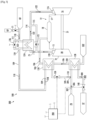
FIG. 3 illustrates a schematic of another exemplary embodiment of agas turbine system 300, in accordance with embodiments of the present invention. As shown, a second feedwater supply line 70 may be fluidly coupled to thewater circuit 108, such that thewater circuit 108 is fluidly coupled to, and extending between, the first feedwater supply line 68, the second feedwater supply line 70, and thereturn water line 37. In exemplary embodiments, thewater circuit 108 may be fluidly coupled to theHRSG 32 of the combinedcycle power plant 10. For example, As shown inFIGS. 1 and2 collectively, the first feedwater supply line 68 may fluidly extend from an outlet of theHPECON 48 to thewater circuit 108. Similarly, the second feedwater supply line 70 may fluidly extend from an outlet of theIPECON 44 to thewater circuit 108. In such embodiments, thereturn water line 37 may fluidly extend from thewater circuit 108 to thecondenser 36. - In other embodiments, the
gas turbine system 300 shown inFIG. 3 may be a standalone system, such that thesystem 300 is not coupled to theCCPP 10 shown inFIG. 1 . In such embodiments, the first feedwater supply line 68 may be coupled to a first independent feed water supply (such as a pressurized storage tank), the second feedwater supply line 70 may be coupled to a second independent feed water supply (such as a pressurized storage tank), and thereturn water line 37 may be coupled to an independent water return tank or condenser. - In the embodiment shown in
FIG. 3 , thegas turbine system 300 may include asecond water line 302 that extends between the second feedwater supply line 70 and thereturn water line 37. In such embodiments, anoutlet 304 of thefirst water line 109 may be fluidly coupled to thesecond water line 302 downstream from (e.g. immediately downstream from) the second feedwater supply line 70. In other embodiments (not shown), thefirst water line 109 and the secondwater supply line 302 may be fluidly isolated from one another, such that they separately fluidly couple to thereturn water line 37. - As shown in
FIG. 3 , the second feedwater supply line 70 may supply a second flow of water 306 (e.g. from the outlet of theIPECON 44 shown inFIG. 1 ) at a second temperature and second pressure. Upon exiting the feedwater supply line 70, the second flow ofwater 306 may be a different temperature and pressure than the first flow ofwater 110 is when exiting the first feedwater supply line 68. For example, the first flow ofwater 110 may be at a higher temperature and pressure than the second flow ofwater 306 upon exiting the respective feed water supplies 68, 70. As shown inFIG. 3 , the first flow ofwater 110 and the second flow ofwater 306 may mix together at theoutlet 304 of thefirst water line 109 to form a third flow ofwater 308. - In exemplary embodiments, as shown in
FIG. 3 , athird heat exchanger 128 may thermally couple thesecond water line 302 to thefuel supply line 104 for transferring heat from the water to the fuel. For example, both thesecond water line 302 and thefuel supply line 104 may extend through thethird heat exchanger 128, in order for heat to be transferred from the third flow ofwater 308 to the flow offuel 106. In this way, the temperature of the flow offuel 106 may be increased when exiting thethird heat exchanger 128, and the temperature of the third flow ofwater 110 may be decreased when exiting thethird heat exchanger 128. - In specific embodiments, the third flow of
water 308 may have a temperature of between about 450°F (approximately 230°C) and about 500°F (approximately 260°C) when entering thethird heat exchanger 128. Upon exiting thesecond heat exchanger 126, the first flow ofwater 110 may have a temperature of about 120°F (approximately 50°C) and about 160°F (approximately 70°C). This may be an improvement over prior designs, as the third flow ofwater 308 has an increased temperature due to thefirst heat exchanger 124 being positioned upstream (due to the first heat exchanger extracting heat energy from the extraction-air 122). - As shown in
FIG. 3 , thethird heat exchanger 128 may be disposed downstream from the first and thesecond heat exchangers water circuit 108. For example, thethird heat exchanger 128 may be disposed immediately downstream from theoutlet 304 of thefirst water line 109 and immediately upstream from thereturn water line 37. In the embodiment shown inFIG. 3 , the secondwater line valve 140 may be positioned on thesecond water line 302. Further, thethird heat exchanger 128 may be positioned upstream from thesecond heat exchanger 126 with respect to the flow offuel 106 in thefuel supply line 104. In this way, thethird heat exchanger 128 may be the downstream-most heat exchanger coupled to thewater circuit 108 with respect to the flow of water therethrough, and thethird heat exchanger 128 may be the upstream-most heat exchanger coupled to thefuel supply line 104 with respect to the flow offuel 106 therethrough. - In the embodiments shown in
FIGS. 1-3 , thewater circuit 108, thefuel supply line 104, and the extraction-air 114 may each be fluidly isolated from one another but may be in thermal communication with one another via thevarious heat exchangers heat exchangers heat exchangers - In operation, the
gas turbine systems heat exchangers cycle power plant 10. For example, theheat exchangers air 122 and preheat thefuel 106, which provides increased efficiency for thegas turbine 12 and theCCPP 10.
Claims (19)
- A gas turbine system comprising:a gas turbine (12) having a compressor section (20), a turbine section (16) and a combustor section (18) disposed downstream from the compressor section and upstream from the turbine section, the combustor section in fluid communication with a fuel supply (102) via a fuel supply line (104);a water circuit (108) fluidly coupled to and extending between a first feed water supply line (68) and a return water line (37), the water circuit comprising a first water lin, (109) extending between the first feed water supply line and the return water line;an extraction-air line (114) extending between an inlet port (120) on the compressor section and an outlet port;a first heat exchanger (124) thermally coupling the first water line to the extraction-air line for transferring heat from a flow of extraction-air within the extraction-air line to a flow of water within the water circuit; anda second heat exchanger (126) thermally coupling the first water line to the fuel supply line for transferring heat from the flow of water within the water circuit to a flow of fuel within the fuel supply line,characterized in that the second heat exchanger is disposed immediately downstream from the first heat exchanger with respect to the flow water within the water circuit such that the water from the first heat exchanger enters the second heat exchanger.
- The gas turbine system as in claim 1, further comprising a cooling water supply line (69) fluidly coupled to the water circuit upstream of the first heat exchanger with respect to the flow of water.
- The gas turbine system as in claim 1, wherein the water circuit further comprises a second feed water supply line (70) fluidly coupled to the water circuit upstream of the return water line.
- The gas turbine system as in claim 3, wherein a second water line (302) extends between the second feed water supply line and the return water line.
- The gas turbine system as in claim 4, wherein a third heat exchanger (128) thermally couples the water circuit to the fuel supply line for transferring heat from the flow of water to the fuel.
- The gas turbine system as in claim 5, wherein the first water line is fluidly coupled to the second water line upstream from the third heat exchanger with respect to the flow of water within the water circuit.
- The gas turbine system as in claim 5, wherein the third heat exchanger is disposed upstream from the second heat exchanger with respect to the flow of fuel.
- The gas turbine system as in claim 1, wherein the water circuit and the extraction-air line each include a bypass line (111, 115).
- The gas turbine system as in claim 1, wherein the water circuit includes one or more valves actuatable between a closed position and an open position by a controller (200).
- A combined cycle power plant (CCPP) comprising a steam turbine (22), a heat recovery steam generator (HRSG), the HRSG including a high-pressure economizer (HPECON), wherein a first water supply line extends from an outlet of the HPECON and out of the HRSG and a gas turbine system according to any of claims 1-9.
- The CCPP as in claim 10, wherein the second heat exchanger is disposed downstream from the first heat exchanger with respect to the flow water within the water circuit.
- The CCPP as in claim 10, wherein the cooling water supply line is fluidly coupled to the water circuit upstream of the first heat exchanger with respect to the flow of water.
- The CCPP as in claim 10, wherein the HRSG further comprises an intermediate-pressure economizer (IPECON), wherein the second feed water supply line extends from an outlet of the IPECON and out of the HRSG, and wherein the second feed water supply line is fluidly coupled to the water circuit upstream of the return water line.
- The CCPP as in claim 13, wherein the second water line extends between the second feed water supply line and the return water line.
- The CCPP as in claim 14, wherein the third heat exchanger thermally couples the water circuit to the fuel supply line for transferring heat from the flow of water to the fuel.
- The CCPP as in claim 15, wherein the first water line is fluidly coupled to the second water line upstream from the third heat exchanger with respect to the flow of water within the water circuit.
- The CCPP as in claim 15, wherein the third heat exchanger is disposed upstream from the second heat exchanger with respect to the flow of fuel.
- The CCPP as in claim 10, wherein the water circuit and the extraction-air line each include a bypass line.
- The CCPP as in claim 10, wherein the water circuit includes one or more valves actuatable between a closed position and an open position by a controller.
Priority Applications (4)
| Application Number | Priority Date | Filing Date | Title |
|---|---|---|---|
| EP21315061.8A EP4071338B1 (en) | 2021-04-08 | 2021-04-08 | Gas turbine system having serial heat exchangers |
| US17/403,101 US11629618B2 (en) | 2021-04-08 | 2021-08-16 | Combined cycle power plant having serial heat exchangers |
| JP2022046454A JP2022161839A (en) | 2021-04-08 | 2022-03-23 | Combined cycle power plant having serial heat exchangers |
| CN202210371152.7A CN115199365A (en) | 2021-04-08 | 2022-04-08 | Combined cycle power plant with series heat exchanger |
Applications Claiming Priority (1)
| Application Number | Priority Date | Filing Date | Title |
|---|---|---|---|
| EP21315061.8A EP4071338B1 (en) | 2021-04-08 | 2021-04-08 | Gas turbine system having serial heat exchangers |
Publications (2)
| Publication Number | Publication Date |
|---|---|
| EP4071338A1 EP4071338A1 (en) | 2022-10-12 |
| EP4071338B1 true EP4071338B1 (en) | 2024-01-31 |
Family
ID=75825772
Family Applications (1)
| Application Number | Title | Priority Date | Filing Date |
|---|---|---|---|
| EP21315061.8A Active EP4071338B1 (en) | 2021-04-08 | 2021-04-08 | Gas turbine system having serial heat exchangers |
Country Status (4)
| Country | Link |
|---|---|
| US (1) | US11629618B2 (en) |
| EP (1) | EP4071338B1 (en) |
| JP (1) | JP2022161839A (en) |
| CN (1) | CN115199365A (en) |
Families Citing this family (2)
| Publication number | Priority date | Publication date | Assignee | Title |
|---|---|---|---|---|
| WO2023157708A1 (en) * | 2022-02-18 | 2023-08-24 | 三菱重工業株式会社 | Steam turbine system |
| KR102737033B1 (en) | 2022-11-24 | 2024-12-02 | 두산에너빌리티 주식회사 | Combined power plant and operating method of the same |
Family Cites Families (11)
| Publication number | Priority date | Publication date | Assignee | Title |
|---|---|---|---|---|
| JP3690972B2 (en) * | 2000-08-08 | 2005-08-31 | 三菱重工業株式会社 | Steam cooled gas turbine |
| JP4395254B2 (en) * | 2000-11-13 | 2010-01-06 | 三菱重工業株式会社 | Combined cycle gas turbine |
| JP3716188B2 (en) * | 2001-04-10 | 2005-11-16 | 三菱重工業株式会社 | Gas turbine combined plant |
| US8813471B2 (en) * | 2011-06-29 | 2014-08-26 | General Electric Company | System for fuel gas moisturization and heating |
| JP2013199925A (en) * | 2012-02-21 | 2013-10-03 | Mitsubishi Heavy Ind Ltd | Gas turbine equipment |
| EP2824293A1 (en) * | 2013-07-08 | 2015-01-14 | Alstom Technology Ltd | Power plant with integrated fuel gas preheating |
| US20150322822A1 (en) * | 2014-05-12 | 2015-11-12 | General Electric Company | Simplified water injection system for combined cycle power plant |
| JP6550659B2 (en) * | 2015-07-24 | 2019-07-31 | 三菱日立パワーシステムズ株式会社 | Water supply method, water supply system for carrying out this method, steam generating equipment provided with water supply system |
| US10017032B2 (en) * | 2016-02-16 | 2018-07-10 | The Boeing Company | Thermal management systems and methods |
| KR102165976B1 (en) * | 2016-03-29 | 2020-10-15 | 미츠비시 쥬고교 가부시키가이샤 | Gas turbine plant and its operating method |
| JP7269761B2 (en) * | 2019-03-15 | 2023-05-09 | 三菱重工業株式会社 | Raw material fluid processing plant and raw material fluid processing method |
-
2021
- 2021-04-08 EP EP21315061.8A patent/EP4071338B1/en active Active
- 2021-08-16 US US17/403,101 patent/US11629618B2/en active Active
-
2022
- 2022-03-23 JP JP2022046454A patent/JP2022161839A/en active Pending
- 2022-04-08 CN CN202210371152.7A patent/CN115199365A/en active Pending
Also Published As
| Publication number | Publication date |
|---|---|
| EP4071338A1 (en) | 2022-10-12 |
| US11629618B2 (en) | 2023-04-18 |
| JP2022161839A (en) | 2022-10-21 |
| US20220325639A1 (en) | 2022-10-13 |
| CN115199365A (en) | 2022-10-18 |
Similar Documents
| Publication | Publication Date | Title |
|---|---|---|
| CN102257248B (en) | Waste heat steam generator and the method for moving for improving waste heat steam generator | |
| US6269626B1 (en) | Regenerative fuel heating system | |
| EP4080019B1 (en) | Gas turbine heat recovery system and method | |
| KR102719198B1 (en) | Fuel preheating system for a combustion turbine engine | |
| CN103477034B (en) | The reheater of supercritical heat recovery steam generator and Supercritical Evaporation device are arranged | |
| JP2009092372A (en) | Supercritical steam combined cycle and method | |
| CN101644193A (en) | System and assemblies for pre-heating fuel in a combined cycle power plant | |
| EP4071338B1 (en) | Gas turbine system having serial heat exchangers | |
| US20250223914A1 (en) | Combined cycle power plant having a carbon capture system with a dedicated steam turbine | |
| EP3077632B1 (en) | Combined cycle system | |
| US20040025510A1 (en) | Method for operating a gas and steam turbine installation and corresponding installation | |
| US10287922B2 (en) | Steam turbine plant, combined cycle plant provided with same, and method of operating steam turbine plant | |
| US20240426243A1 (en) | Combined cycle power plant having reduced parasitic pumping losses | |
| US12031457B2 (en) | Combined cycle power plant having reduced parasitic pumping losses | |
| CN109804140B (en) | Steam and gas turbine installation | |
| JP2025506925A (en) | Thermal energy storage system and method having a heat recovery steam generator - Patents.com | |
| CN120187938A (en) | System for down-regulation of reheat steam temperature in a heat recovery steam generator |
Legal Events
| Date | Code | Title | Description |
|---|---|---|---|
| PUAI | Public reference made under article 153(3) epc to a published international application that has entered the european phase |
Free format text: ORIGINAL CODE: 0009012 |
|
| STAA | Information on the status of an ep patent application or granted ep patent |
Free format text: STATUS: THE APPLICATION HAS BEEN PUBLISHED |
|
| AK | Designated contracting states |
Kind code of ref document: A1 Designated state(s): AL AT BE BG CH CY CZ DE DK EE ES FI FR GB GR HR HU IE IS IT LI LT LU LV MC MK MT NL NO PL PT RO RS SE SI SK SM TR |
|
| STAA | Information on the status of an ep patent application or granted ep patent |
Free format text: STATUS: REQUEST FOR EXAMINATION WAS MADE |
|
| 17P | Request for examination filed |
Effective date: 20230202 |
|
| RBV | Designated contracting states (corrected) |
Designated state(s): AL AT BE BG CH CY CZ DE DK EE ES FI FR GB GR HR HU IE IS IT LI LT LU LV MC MK MT NL NO PL PT RO RS SE SI SK SM TR |
|
| GRAP | Despatch of communication of intention to grant a patent |
Free format text: ORIGINAL CODE: EPIDOSNIGR1 |
|
| STAA | Information on the status of an ep patent application or granted ep patent |
Free format text: STATUS: GRANT OF PATENT IS INTENDED |
|
| INTG | Intention to grant announced |
Effective date: 20230825 |
|
| RAP1 | Party data changed (applicant data changed or rights of an application transferred) |
Owner name: GENERAL ELECTRIC TECHNOLOGY GMBH |
|
| GRAS | Grant fee paid |
Free format text: ORIGINAL CODE: EPIDOSNIGR3 |
|
| GRAA | (expected) grant |
Free format text: ORIGINAL CODE: 0009210 |
|
| STAA | Information on the status of an ep patent application or granted ep patent |
Free format text: STATUS: THE PATENT HAS BEEN GRANTED |
|
| AK | Designated contracting states |
Kind code of ref document: B1 Designated state(s): AL AT BE BG CH CY CZ DE DK EE ES FI FR GB GR HR HU IE IS IT LI LT LU LV MC MK MT NL NO PL PT RO RS SE SI SK SM TR |
|
| REG | Reference to a national code |
Ref country code: GB Ref legal event code: FG4D Ref country code: CH Ref legal event code: EP |
|
| REG | Reference to a national code |
Ref country code: DE Ref legal event code: R096 Ref document number: 602021008977 Country of ref document: DE |
|
| REG | Reference to a national code |
Ref country code: IE Ref legal event code: FG4D |
|
| REG | Reference to a national code |
Ref country code: LT Ref legal event code: MG9D |
|
| REG | Reference to a national code |
Ref country code: NL Ref legal event code: MP Effective date: 20240131 |
|
| PG25 | Lapsed in a contracting state [announced via postgrant information from national office to epo] |
Ref country code: IS Free format text: LAPSE BECAUSE OF FAILURE TO SUBMIT A TRANSLATION OF THE DESCRIPTION OR TO PAY THE FEE WITHIN THE PRESCRIBED TIME-LIMIT Effective date: 20240531 |
|
| PG25 | Lapsed in a contracting state [announced via postgrant information from national office to epo] |
Ref country code: LT Free format text: LAPSE BECAUSE OF FAILURE TO SUBMIT A TRANSLATION OF THE DESCRIPTION OR TO PAY THE FEE WITHIN THE PRESCRIBED TIME-LIMIT Effective date: 20240131 |
|
| PG25 | Lapsed in a contracting state [announced via postgrant information from national office to epo] |
Ref country code: GR Free format text: LAPSE BECAUSE OF FAILURE TO SUBMIT A TRANSLATION OF THE DESCRIPTION OR TO PAY THE FEE WITHIN THE PRESCRIBED TIME-LIMIT Effective date: 20240501 |
|
| REG | Reference to a national code |
Ref country code: AT Ref legal event code: MK05 Ref document number: 1654007 Country of ref document: AT Kind code of ref document: T Effective date: 20240131 |
|
| PG25 | Lapsed in a contracting state [announced via postgrant information from national office to epo] |
Ref country code: HR Free format text: LAPSE BECAUSE OF FAILURE TO SUBMIT A TRANSLATION OF THE DESCRIPTION OR TO PAY THE FEE WITHIN THE PRESCRIBED TIME-LIMIT Effective date: 20240131 Ref country code: NL Free format text: LAPSE BECAUSE OF FAILURE TO SUBMIT A TRANSLATION OF THE DESCRIPTION OR TO PAY THE FEE WITHIN THE PRESCRIBED TIME-LIMIT Effective date: 20240131 Ref country code: RS Free format text: LAPSE BECAUSE OF FAILURE TO SUBMIT A TRANSLATION OF THE DESCRIPTION OR TO PAY THE FEE WITHIN THE PRESCRIBED TIME-LIMIT Effective date: 20240430 |
|
| PG25 | Lapsed in a contracting state [announced via postgrant information from national office to epo] |
Ref country code: ES Free format text: LAPSE BECAUSE OF FAILURE TO SUBMIT A TRANSLATION OF THE DESCRIPTION OR TO PAY THE FEE WITHIN THE PRESCRIBED TIME-LIMIT Effective date: 20240131 |
|
| PG25 | Lapsed in a contracting state [announced via postgrant information from national office to epo] |
Ref country code: AT Free format text: LAPSE BECAUSE OF FAILURE TO SUBMIT A TRANSLATION OF THE DESCRIPTION OR TO PAY THE FEE WITHIN THE PRESCRIBED TIME-LIMIT Effective date: 20240131 |
|
| PG25 | Lapsed in a contracting state [announced via postgrant information from national office to epo] |
Ref country code: RS Free format text: LAPSE BECAUSE OF FAILURE TO SUBMIT A TRANSLATION OF THE DESCRIPTION OR TO PAY THE FEE WITHIN THE PRESCRIBED TIME-LIMIT Effective date: 20240430 Ref country code: NO Free format text: LAPSE BECAUSE OF FAILURE TO SUBMIT A TRANSLATION OF THE DESCRIPTION OR TO PAY THE FEE WITHIN THE PRESCRIBED TIME-LIMIT Effective date: 20240430 Ref country code: NL Free format text: LAPSE BECAUSE OF FAILURE TO SUBMIT A TRANSLATION OF THE DESCRIPTION OR TO PAY THE FEE WITHIN THE PRESCRIBED TIME-LIMIT Effective date: 20240131 Ref country code: LT Free format text: LAPSE BECAUSE OF FAILURE TO SUBMIT A TRANSLATION OF THE DESCRIPTION OR TO PAY THE FEE WITHIN THE PRESCRIBED TIME-LIMIT Effective date: 20240131 Ref country code: IS Free format text: LAPSE BECAUSE OF FAILURE TO SUBMIT A TRANSLATION OF THE DESCRIPTION OR TO PAY THE FEE WITHIN THE PRESCRIBED TIME-LIMIT Effective date: 20240531 Ref country code: HR Free format text: LAPSE BECAUSE OF FAILURE TO SUBMIT A TRANSLATION OF THE DESCRIPTION OR TO PAY THE FEE WITHIN THE PRESCRIBED TIME-LIMIT Effective date: 20240131 Ref country code: GR Free format text: LAPSE BECAUSE OF FAILURE TO SUBMIT A TRANSLATION OF THE DESCRIPTION OR TO PAY THE FEE WITHIN THE PRESCRIBED TIME-LIMIT Effective date: 20240501 Ref country code: FI Free format text: LAPSE BECAUSE OF FAILURE TO SUBMIT A TRANSLATION OF THE DESCRIPTION OR TO PAY THE FEE WITHIN THE PRESCRIBED TIME-LIMIT Effective date: 20240131 Ref country code: ES Free format text: LAPSE BECAUSE OF FAILURE TO SUBMIT A TRANSLATION OF THE DESCRIPTION OR TO PAY THE FEE WITHIN THE PRESCRIBED TIME-LIMIT Effective date: 20240131 Ref country code: BG Free format text: LAPSE BECAUSE OF FAILURE TO SUBMIT A TRANSLATION OF THE DESCRIPTION OR TO PAY THE FEE WITHIN THE PRESCRIBED TIME-LIMIT Effective date: 20240131 Ref country code: AT Free format text: LAPSE BECAUSE OF FAILURE TO SUBMIT A TRANSLATION OF THE DESCRIPTION OR TO PAY THE FEE WITHIN THE PRESCRIBED TIME-LIMIT Effective date: 20240131 |
|
| PG25 | Lapsed in a contracting state [announced via postgrant information from national office to epo] |
Ref country code: PT Free format text: LAPSE BECAUSE OF FAILURE TO SUBMIT A TRANSLATION OF THE DESCRIPTION OR TO PAY THE FEE WITHIN THE PRESCRIBED TIME-LIMIT Effective date: 20240531 Ref country code: PL Free format text: LAPSE BECAUSE OF FAILURE TO SUBMIT A TRANSLATION OF THE DESCRIPTION OR TO PAY THE FEE WITHIN THE PRESCRIBED TIME-LIMIT Effective date: 20240131 |
|
| PG25 | Lapsed in a contracting state [announced via postgrant information from national office to epo] |
Ref country code: SE Free format text: LAPSE BECAUSE OF FAILURE TO SUBMIT A TRANSLATION OF THE DESCRIPTION OR TO PAY THE FEE WITHIN THE PRESCRIBED TIME-LIMIT Effective date: 20240131 Ref country code: PT Free format text: LAPSE BECAUSE OF FAILURE TO SUBMIT A TRANSLATION OF THE DESCRIPTION OR TO PAY THE FEE WITHIN THE PRESCRIBED TIME-LIMIT Effective date: 20240531 Ref country code: PL Free format text: LAPSE BECAUSE OF FAILURE TO SUBMIT A TRANSLATION OF THE DESCRIPTION OR TO PAY THE FEE WITHIN THE PRESCRIBED TIME-LIMIT Effective date: 20240131 Ref country code: LV Free format text: LAPSE BECAUSE OF FAILURE TO SUBMIT A TRANSLATION OF THE DESCRIPTION OR TO PAY THE FEE WITHIN THE PRESCRIBED TIME-LIMIT Effective date: 20240131 |
|
| PG25 | Lapsed in a contracting state [announced via postgrant information from national office to epo] |
Ref country code: DK Free format text: LAPSE BECAUSE OF FAILURE TO SUBMIT A TRANSLATION OF THE DESCRIPTION OR TO PAY THE FEE WITHIN THE PRESCRIBED TIME-LIMIT Effective date: 20240131 |
|
| PG25 | Lapsed in a contracting state [announced via postgrant information from national office to epo] |
Ref country code: SM Free format text: LAPSE BECAUSE OF FAILURE TO SUBMIT A TRANSLATION OF THE DESCRIPTION OR TO PAY THE FEE WITHIN THE PRESCRIBED TIME-LIMIT Effective date: 20240131 |
|
| PG25 | Lapsed in a contracting state [announced via postgrant information from national office to epo] |
Ref country code: EE Free format text: LAPSE BECAUSE OF FAILURE TO SUBMIT A TRANSLATION OF THE DESCRIPTION OR TO PAY THE FEE WITHIN THE PRESCRIBED TIME-LIMIT Effective date: 20240131 Ref country code: CZ Free format text: LAPSE BECAUSE OF FAILURE TO SUBMIT A TRANSLATION OF THE DESCRIPTION OR TO PAY THE FEE WITHIN THE PRESCRIBED TIME-LIMIT Effective date: 20240131 |
|
| PG25 | Lapsed in a contracting state [announced via postgrant information from national office to epo] |
Ref country code: SK Free format text: LAPSE BECAUSE OF FAILURE TO SUBMIT A TRANSLATION OF THE DESCRIPTION OR TO PAY THE FEE WITHIN THE PRESCRIBED TIME-LIMIT Effective date: 20240131 |
|
| PG25 | Lapsed in a contracting state [announced via postgrant information from national office to epo] |
Ref country code: SM Free format text: LAPSE BECAUSE OF FAILURE TO SUBMIT A TRANSLATION OF THE DESCRIPTION OR TO PAY THE FEE WITHIN THE PRESCRIBED TIME-LIMIT Effective date: 20240131 Ref country code: SK Free format text: LAPSE BECAUSE OF FAILURE TO SUBMIT A TRANSLATION OF THE DESCRIPTION OR TO PAY THE FEE WITHIN THE PRESCRIBED TIME-LIMIT Effective date: 20240131 Ref country code: RO Free format text: LAPSE BECAUSE OF FAILURE TO SUBMIT A TRANSLATION OF THE DESCRIPTION OR TO PAY THE FEE WITHIN THE PRESCRIBED TIME-LIMIT Effective date: 20240131 Ref country code: EE Free format text: LAPSE BECAUSE OF FAILURE TO SUBMIT A TRANSLATION OF THE DESCRIPTION OR TO PAY THE FEE WITHIN THE PRESCRIBED TIME-LIMIT Effective date: 20240131 Ref country code: DK Free format text: LAPSE BECAUSE OF FAILURE TO SUBMIT A TRANSLATION OF THE DESCRIPTION OR TO PAY THE FEE WITHIN THE PRESCRIBED TIME-LIMIT Effective date: 20240131 Ref country code: CZ Free format text: LAPSE BECAUSE OF FAILURE TO SUBMIT A TRANSLATION OF THE DESCRIPTION OR TO PAY THE FEE WITHIN THE PRESCRIBED TIME-LIMIT Effective date: 20240131 |
|
| REG | Reference to a national code |
Ref country code: DE Ref legal event code: R097 Ref document number: 602021008977 Country of ref document: DE |
|
| PG25 | Lapsed in a contracting state [announced via postgrant information from national office to epo] |
Ref country code: MC Free format text: LAPSE BECAUSE OF FAILURE TO SUBMIT A TRANSLATION OF THE DESCRIPTION OR TO PAY THE FEE WITHIN THE PRESCRIBED TIME-LIMIT Effective date: 20240131 |
|
| PG25 | Lapsed in a contracting state [announced via postgrant information from national office to epo] |
Ref country code: MC Free format text: LAPSE BECAUSE OF FAILURE TO SUBMIT A TRANSLATION OF THE DESCRIPTION OR TO PAY THE FEE WITHIN THE PRESCRIBED TIME-LIMIT Effective date: 20240131 |
|
| REG | Reference to a national code |
Ref country code: CH Ref legal event code: PL |
|
| PG25 | Lapsed in a contracting state [announced via postgrant information from national office to epo] |
Ref country code: IT Free format text: LAPSE BECAUSE OF FAILURE TO SUBMIT A TRANSLATION OF THE DESCRIPTION OR TO PAY THE FEE WITHIN THE PRESCRIBED TIME-LIMIT Effective date: 20240131 |
|
| PLBE | No opposition filed within time limit |
Free format text: ORIGINAL CODE: 0009261 |
|
| STAA | Information on the status of an ep patent application or granted ep patent |
Free format text: STATUS: NO OPPOSITION FILED WITHIN TIME LIMIT |
|
| PG25 | Lapsed in a contracting state [announced via postgrant information from national office to epo] |
Ref country code: LU Free format text: LAPSE BECAUSE OF NON-PAYMENT OF DUE FEES Effective date: 20240408 |
|
| PG25 | Lapsed in a contracting state [announced via postgrant information from national office to epo] |
Ref country code: LU Free format text: LAPSE BECAUSE OF NON-PAYMENT OF DUE FEES Effective date: 20240408 Ref country code: IT Free format text: LAPSE BECAUSE OF FAILURE TO SUBMIT A TRANSLATION OF THE DESCRIPTION OR TO PAY THE FEE WITHIN THE PRESCRIBED TIME-LIMIT Effective date: 20240131 |
|
| 26N | No opposition filed |
Effective date: 20241101 |
|
| PG25 | Lapsed in a contracting state [announced via postgrant information from national office to epo] |
Ref country code: FR Free format text: LAPSE BECAUSE OF NON-PAYMENT OF DUE FEES Effective date: 20240430 |
|
| PG25 | Lapsed in a contracting state [announced via postgrant information from national office to epo] |
Ref country code: FR Free format text: LAPSE BECAUSE OF NON-PAYMENT OF DUE FEES Effective date: 20240430 Ref country code: CH Free format text: LAPSE BECAUSE OF NON-PAYMENT OF DUE FEES Effective date: 20240430 |
|
| PG25 | Lapsed in a contracting state [announced via postgrant information from national office to epo] |
Ref country code: IE Free format text: LAPSE BECAUSE OF NON-PAYMENT OF DUE FEES Effective date: 20240408 |
|
| PG25 | Lapsed in a contracting state [announced via postgrant information from national office to epo] |
Ref country code: SI Free format text: LAPSE BECAUSE OF FAILURE TO SUBMIT A TRANSLATION OF THE DESCRIPTION OR TO PAY THE FEE WITHIN THE PRESCRIBED TIME-LIMIT Effective date: 20240131 |
|
| PGFP | Annual fee paid to national office [announced via postgrant information from national office to epo] |
Ref country code: DE Payment date: 20250319 Year of fee payment: 5 |
|
| PG25 | Lapsed in a contracting state [announced via postgrant information from national office to epo] |
Ref country code: CY Free format text: LAPSE BECAUSE OF FAILURE TO SUBMIT A TRANSLATION OF THE DESCRIPTION OR TO PAY THE FEE WITHIN THE PRESCRIBED TIME-LIMIT; INVALID AB INITIO Effective date: 20210408 |
|
| PG25 | Lapsed in a contracting state [announced via postgrant information from national office to epo] |
Ref country code: HU Free format text: LAPSE BECAUSE OF FAILURE TO SUBMIT A TRANSLATION OF THE DESCRIPTION OR TO PAY THE FEE WITHIN THE PRESCRIBED TIME-LIMIT; INVALID AB INITIO Effective date: 20210408 |
|
| GBPC | Gb: european patent ceased through non-payment of renewal fee |
Effective date: 20250408 |
|
| PG25 | Lapsed in a contracting state [announced via postgrant information from national office to epo] |
Ref country code: GB Free format text: LAPSE BECAUSE OF NON-PAYMENT OF DUE FEES Effective date: 20250408 |
|
| PGFP | Annual fee paid to national office [announced via postgrant information from national office to epo] |
Ref country code: BE Payment date: 20260319 Year of fee payment: 6 |