EP4071276B1 - Elektrolyseanordnung für die alkalische elektrolyse - Google Patents
Elektrolyseanordnung für die alkalische elektrolyse Download PDFInfo
- Publication number
- EP4071276B1 EP4071276B1 EP21020193.5A EP21020193A EP4071276B1 EP 4071276 B1 EP4071276 B1 EP 4071276B1 EP 21020193 A EP21020193 A EP 21020193A EP 4071276 B1 EP4071276 B1 EP 4071276B1
- Authority
- EP
- European Patent Office
- Prior art keywords
- control valve
- cathode
- anode
- electrolysis
- electrolyte
- Prior art date
- Legal status (The legal status is an assumption and is not a legal conclusion. Google has not performed a legal analysis and makes no representation as to the accuracy of the status listed.)
- Active
Links
Images


Classifications
-
- C—CHEMISTRY; METALLURGY
- C25—ELECTROLYTIC OR ELECTROPHORETIC PROCESSES; APPARATUS THEREFOR
- C25B—ELECTROLYTIC OR ELECTROPHORETIC PROCESSES FOR THE PRODUCTION OF COMPOUNDS OR NON-METALS; APPARATUS THEREFOR
- C25B1/00—Electrolytic production of inorganic compounds or non-metals
- C25B1/01—Products
- C25B1/02—Hydrogen or oxygen
- C25B1/04—Hydrogen or oxygen by electrolysis of water
-
- C—CHEMISTRY; METALLURGY
- C25—ELECTROLYTIC OR ELECTROPHORETIC PROCESSES; APPARATUS THEREFOR
- C25B—ELECTROLYTIC OR ELECTROPHORETIC PROCESSES FOR THE PRODUCTION OF COMPOUNDS OR NON-METALS; APPARATUS THEREFOR
- C25B15/00—Operating or servicing cells
-
- C—CHEMISTRY; METALLURGY
- C25—ELECTROLYTIC OR ELECTROPHORETIC PROCESSES; APPARATUS THEREFOR
- C25B—ELECTROLYTIC OR ELECTROPHORETIC PROCESSES FOR THE PRODUCTION OF COMPOUNDS OR NON-METALS; APPARATUS THEREFOR
- C25B15/00—Operating or servicing cells
- C25B15/08—Supplying or removing reactants or electrolytes; Regeneration of electrolytes
- C25B15/083—Separating products
-
- C—CHEMISTRY; METALLURGY
- C25—ELECTROLYTIC OR ELECTROPHORETIC PROCESSES; APPARATUS THEREFOR
- C25B—ELECTROLYTIC OR ELECTROPHORETIC PROCESSES FOR THE PRODUCTION OF COMPOUNDS OR NON-METALS; APPARATUS THEREFOR
- C25B15/00—Operating or servicing cells
- C25B15/08—Supplying or removing reactants or electrolytes; Regeneration of electrolytes
- C25B15/087—Recycling of electrolyte to electrochemical cell
-
- C—CHEMISTRY; METALLURGY
- C25—ELECTROLYTIC OR ELECTROPHORETIC PROCESSES; APPARATUS THEREFOR
- C25B—ELECTROLYTIC OR ELECTROPHORETIC PROCESSES FOR THE PRODUCTION OF COMPOUNDS OR NON-METALS; APPARATUS THEREFOR
- C25B9/00—Cells or assemblies of cells; Constructional parts of cells; Assemblies of constructional parts, e.g. electrode-diaphragm assemblies; Process-related cell features
- C25B9/05—Pressure cells
-
- C—CHEMISTRY; METALLURGY
- C25—ELECTROLYTIC OR ELECTROPHORETIC PROCESSES; APPARATUS THEREFOR
- C25B—ELECTROLYTIC OR ELECTROPHORETIC PROCESSES FOR THE PRODUCTION OF COMPOUNDS OR NON-METALS; APPARATUS THEREFOR
- C25B9/00—Cells or assemblies of cells; Constructional parts of cells; Assemblies of constructional parts, e.g. electrode-diaphragm assemblies; Process-related cell features
- C25B9/60—Constructional parts of cells
- C25B9/65—Means for supplying current; Electrode connections; Electric inter-cell connections
-
- C—CHEMISTRY; METALLURGY
- C25—ELECTROLYTIC OR ELECTROPHORETIC PROCESSES; APPARATUS THEREFOR
- C25B—ELECTROLYTIC OR ELECTROPHORETIC PROCESSES FOR THE PRODUCTION OF COMPOUNDS OR NON-METALS; APPARATUS THEREFOR
- C25B9/00—Cells or assemblies of cells; Constructional parts of cells; Assemblies of constructional parts, e.g. electrode-diaphragm assemblies; Process-related cell features
- C25B9/70—Assemblies comprising two or more cells
- C25B9/73—Assemblies comprising two or more cells of the filter-press type
- C25B9/77—Assemblies comprising two or more cells of the filter-press type having diaphragms
-
- Y—GENERAL TAGGING OF NEW TECHNOLOGICAL DEVELOPMENTS; GENERAL TAGGING OF CROSS-SECTIONAL TECHNOLOGIES SPANNING OVER SEVERAL SECTIONS OF THE IPC; TECHNICAL SUBJECTS COVERED BY FORMER USPC CROSS-REFERENCE ART COLLECTIONS [XRACs] AND DIGESTS
- Y02—TECHNOLOGIES OR APPLICATIONS FOR MITIGATION OR ADAPTATION AGAINST CLIMATE CHANGE
- Y02E—REDUCTION OF GREENHOUSE GAS [GHG] EMISSIONS, RELATED TO ENERGY GENERATION, TRANSMISSION OR DISTRIBUTION
- Y02E60/00—Enabling technologies; Technologies with a potential or indirect contribution to GHG emissions mitigation
- Y02E60/30—Hydrogen technology
- Y02E60/36—Hydrogen production from non-carbon containing sources, e.g. by water electrolysis
Definitions
- the invention relates to an electrolysis arrangement for the electrochemical production of hydrogen and oxygen from an alkaline electrolysis medium.
- electrolyte medium In alkaline electrolysis of water, a highly concentrated lye solution is used as an electrolyte medium.
- aqueous potassium hydroxide with a concentration of 1 mol/l (1 M) up to 6 mol/l (6 M) is used as electrolyte.
- mixing of the lye withdrawn from the anode and cathode section of the stack is done after separation of the hydrogen and oxygen product gases to balance the lye concentration of the cycle streams.
- the stream with balanced lye concentration is split and the separated streams are fed to the anode and cathode section of the stack respectively for further water splitting. If the concentrations of the lye streams are not balanced, the concentrations would continue to diverge, which causes efficiency losses on the electrolyser performance. This becomes apparent from the dependence of electrical conductivity of the lye on the lye concentration. There is a distinct maximum in the conductivity corresponding to an optimal lye concentration from the point of view of ohmic losses of the electrolyser.
- a concentrated aqueous KOH solution has the highest specific electrical conductivity at about 33 % wt.
- the specific electrical conductivity therefore decreases both at higher and lower KOH concentrations.
- the lye concentration on the cathode side can lead to crystallisation, as the crystallisation temperature rises steeply in case of KOH with increasing lye concentration.
- EP3770304 describes an apparatus for alkaline water electrolysis with gas-liquid separators.
- HTO crossover is in particular relevant. Therefore, a potential risk of operation of an electrolyser is that a lower explosion limit (LEL) for hydrogen in oxygen (HTO) in the anode section of the electrolyser might get exceeded.
- LEL lower explosion limit
- HTO hydrogen in oxygen concentration
- the LEL when capacity utilization is low, the LEL might get exceeded when the electrolyser is operated with full mixing of the lye cycles.
- This is in particular relevant for those alkaline electrolysers, which use electrical power from renewable energy sources, for example wind power or solar power.
- renewable energy sources for example wind power or solar power.
- the direct current required to operate the electrolyser is supplied with constant current density.
- the problem is not limited to fluctuating renewable energy supply, but also in terms of fluctuating power supply in cases of grid balancing, dynamic customer demand and the like.
- the problem always occurs in case the electrolyser needs to be shut down, for example to carry out maintenance.
- the minimum production capacity of the electrolyser is limited. In other words, the electrolyser can only be operated safely within a certain operating window. To allow for a larger operating range of the electrolyser, the hydrogen content in the oxygen product stream needs to be reduced, in particular at low production capacities, when also the current density of the direct current supplied to the electrolyser stack is low.
- an object of the present invention is to provide an electrolysis arrangement which enables to switch between mixed mode with full mixing of the lye cycles, separate mode with no mixing of the lye cycles, and also partly mixing of the lye cycles, dependent on the current density of the direct current supplied to the electrolyser.
- a further object of the present invention is to provide an electrolysis arrangement which can be operated safely at changing high and low capacities without exceeding a lower explosion limit threshold for HTO.
- the electrolysis stack comprises a plurality of electrodes, in particular a plurality of anodes and cathodes.
- the electrolysis stack may comprise a plurality of anode chambers and cathode chambers, whereby the anode chambers and cathode chambers form the anode section and the cathode section of the electrolysis stack.
- the number of electrodes, i.e. anodes and cathodes, and anode and cathode chambers respectively, depends on the production capacity, i.e. the size of the electrolyser of the electrolysis arrangement and which type of electrolysis stack is used.
- the electrolysis stack is configured for the production of hydrogen and oxygen from an alkaline electrolysis medium.
- the desired product of the electrolysis arrangement is hydrogen, and oxygen is a byproduct, which is subject to further use or venting.
- the electrolysis medium is aqueous potassium hydroxide (KOH) solution.
- the concentration of the KOH is up to 6 mol/l (6 M).
- oxygen is generated by oxidation of water-bound oxygen (oxidation number minus 2).
- hydrogen is generated by reduction of water-bound hydrogen (oxidation number plus 1).
- the current density of the direct current is the amount of charge per unit time that flows through a unit area of a given cross section.
- the unit area refers to the area of the respective electrode.
- the current density for example, is given in A/m 2 .
- separatator refers to a gas/liquid separator to separate product gas of the electrolysis reaction from liquid electrolyte.
- an anode separator is configured to separate gaseous oxygen from liquid electrolyte and a cathode separator is configured to separate gaseous hydrogen from liquid electrolyte.
- the oxygen generated in the anode section of the electrolysis stack is transported with the electrolyte via the anode pipe system to the anode separator.
- the gaseous oxygen is separated from the liquid electrolyte.
- the oxygen depleted electrolyte which still comprises dissolved oxygen, is further transported via the anode pipe system back to the anode section of the electrolysis stack, where it is subjected again to the electrolysis reaction.
- the electrolyte is circulated via the anode pipe system between the anode section of the electrolysis stack and the anode separator.
- the electrolyte circulating within the anode pipe system is also referred to as the anolyte of the electrolysis arrangement.
- the hydrogen generated in the cathode section of the electrolysis stack is transported with the electrolyte via the cathode pipe system to the cathode separator.
- the cathode separator In the cathode separator, the gaseous hydrogen is separated from the liquid electrolyte.
- the hydrogen depleted electrolyte, which still comprises dissolved hydrogen, is further transported via the cathode pipe system back to the cathode section of the electrolysis stack, where it is subjected again to the electrolysis reaction.
- the electrolyte is circulated via the cathode pipe system between the cathode section of the electrolysis stack and the cathode separator.
- the electrolysis medium circulating in the cathode pipe system is also referred to as the catholyte of the electrolysis arrangement.
- the electrolysis arrangement according to the invention allows to react to fluctuating direct current densities supplied to the electrolysis stack in such a way that the LEL for HTO is not exceeded even at low production capacities.
- This is solved according to the invention such that the first control valve, the second control valve, the third control valve, the first connecting pipe and the second connecting pipe of the electrolysis arrangement are arranged in a way that allows to switch between mixed mode, partly mixed mode and separate mode in terms of the electrolyte circulating in the anode pipe system and the cathode pipe system.
- the oxygen depleted electrolyte withdrawn from the anode separator and the hydrogen depleted electrolyte withdrawn from the cathode separator are supplied fully mixed to the anode section of the electrolysis stack and the cathode section of the electrolysis stack.
- the oxygen depleted electrolyte withdrawn from the anode separator and the hydrogen depleted electrolyte withdrawn from the cathode separator are first fully mixed and then the fully mixed electrolyte is split and separately fed to the anode section and the cathode section of the electrolysis stack.
- the mixed mode is preferably used at the maximum production capacity, or in general at high production capacities, i.e. high current densities, as the HTO and OTH crossover is low at high current densities.
- the mixed mode allows for fast balancing out the concentration differences between the anolyte and the catholyte.
- the oxygen depleted electrolyte withdrawn from the anode separator and the hydrogen depleted electrolyte withdrawn from the cathode separator are supplied partly mixed to the anode section of the electrolysis stack and the cathode section of the electrolysis stack.
- the oxygen depleted electrolyte withdrawn from the anode separator and the hydrogen depleted electrolyte withdrawn from the cathode separator are first partly mixed and then the partly mixed electrolyte, comprising mixed an unmixed electrolyte, is split and separately fed to the anode section and the cathode section of the electrolysis stack.
- the partly mixed mode is preferably used at high and medium production capacities, i.e.
- the HTO and OTH crossover is relatively low at medium current densities, but high enough so that full mixing is not sought.
- the partly mixed mode allows for relatively fast balancing out of concentration differences between the anolyte and the catholyte. For instance, it was found that mixing a fraction of 30 percent of the anolyte and catholyte, related to the volume flow of anolyte and catholyte withdrawn from the anode separator and cathode separator, is sufficient to balance out concentration differences between anolyte and catholyte within a reasonable time period.
- the oxygen depleted electrolyte withdrawn from the anode separator and the hydrogen depleted electrolyte withdrawn from the cathode separator are not mixed at all, but separately fed to the anode section of the electrolysis stack and the cathode section of the electrolysis stack.
- the oxygen depleted electrolyte withdrawn from the anode separator and the hydrogen depleted electrolyte withdrawn from the cathode separator are not mixed at all, but from the outset separately fed to the anode section and the cathode section of the electrolysis stack.
- the separate mode is preferably used at low production capacities or at turndown capacities, i.e.
- a first connecting pipe and a second connecting pipe interconnect the anode pipe system and the cathode pipe system. Without the connecting pipes, the anode pipe system and the cathode pipe system would be completely separate from each other, and no direct material exchange between the anode pipe system and the cathode pipe system, which each form their own circuits, would be possible.
- the connecting pipes provide a connection between the anode pipe system and the cathode pipe system and thus provide direct material exchange between the electrolyte circulating in the anode pipe system and the electrolyte circulating in the cathode pipe system, i.e. the anolyte and the catholyte.
- the first connecting pipe comprises the first control valve.
- the second connecting pipe comprises the third control valve.
- a fraction of oxygen depleted electrolyte withdrawn from the anode separator is transferred from the anode pipe system to the cathode pipe system.
- a fraction of hydrogen depleted electrolyte withdrawn from the cathode separator is transferred from the cathode pipe system to the anode pipe system.
- whether a fraction of anolyte is transferred to the cathode pipe system or a fraction of catholyte is transferred to the anode pipe system depends on where the second control valve is arranged, i.e. either within the anode pipe system or the cathode pipe system.
- the anode pipe system comprises a pump to circulate the electrolyte between the anode section of the electrolysis stack and the anode separator.
- the cathode pipe system comprises a pump to circulate the electrolyte between the cathode section of the electrolysis stack and the cathode separator.
- the electrolysis stack comprises a membrane or a plurality of membranes, also referred to as diaphragm(s), which enables transportation of hydroxyl ions (OH - ) between the anode chambers and the respective cathode chambers, i.e. between the anode section and the cathode section of the electrolysis stack and vice versa.
- the electrolysis stack comprises a plurality of membranes or diaphragms for transportation of hydroxyl ions between the anode section and the cathode section of the electrolysis stack.
- the electrolysis arrangement comprises a water supply to balance the water amount in the system of the electrolysis arrangement, as water is continuously consumed due to the electrolysis reaction.
- the water feed comprises a water storage tank and a pump to supply water to the anode pipe system and/or the cathode pipe system of the electrolysis arrangement.
- the fraction of oxygen depleted electrolyte withdrawn from the anode separator and hydrogen depleted electrolyte withdrawn from the cathode separator that are mixed and supplied to the anode section of the electrolysis stack and the cathode section of the electrolysis stack is from 0 % to 100 % of a total amount of the electrolyte, or from 0,1 % to 100 %, or from 1 % to 100 %, or from 10 % to 90 %, or from 10 % to 50 %, or from 20 % to 40 %.
- the second control valve arranged within the anode pipe system or arranged within the cathode pipe system is arranged downstream to the first connecting pipe.
- the second control valve arranged within the anode pipe system or arranged within the cathode pipe system is arranged upstream to the second connecting pipe.
- the first control valve is fully closed, the second control valve is opened and the third control valve is opened, so that the oxygen depleted electrolyte withdrawn from the anode separator and the hydrogen depleted electrolyte withdrawn from the cathode separator are supplied partly mixed to the anode section of the electrolysis stack and the cathode section of the electrolysis stack.
- the electrolysis arrangement is operated in partly mixed mode, wherein a part of the electrolyte withdrawn from the anode separator and the cathode separator is mixed before it is supplied to the anode section and the cathode section of the electrolysis stack.
- the first control valve is fully closed, the second control valve is opened and the third control valve is fully closed, so that the oxygen depleted electrolyte withdrawn from the anode separator and the hydrogen depleted electrolyte withdrawn from the cathode separator are supplied unmixed to the anode section of the electrolysis stack and the cathode section of the electrolysis stack.
- no material exchange between the anolyte pipe system and the catholyte pipe system is possible.
- the electrolysis arrangement is operated in separate mode or full separate mode, without any mixing of anolyte and catholyte.
- the first control valve is opened, and the second control valve is fully closed, so that the oxygen depleted electrolyte withdrawn from the anode separator and the hydrogen depleted electrolyte withdrawn from the cathode separator are supplied fully mixed to the anode section of the electrolysis stack and the cathode section of the electrolysis stack.
- the electrolysis arrangement is operated in mixed mode or full mixed mode, with full mixing of anolyte and catholyte.
- the fraction of the mixed electrolyte is
- the amount of the fraction of the mixed electrolyte i.e. the electrolyte obtained from mixing of the anolyte withdrawn from the anode separator and the catholyte withdrawn from the cathode separator, is also decreased.
- the amount of the fraction of the mixed electrolyte is decreased and the amount of the fraction of the unmixed electrolyte is increased correspondingly.
- the amount of the fraction of the mixed electrolyte i.e. the electrolyte obtained from mixing of the anolyte withdrawn from the anode separator and the catholyte withdrawn from the cathode separator, is also increased.
- the amount of the fraction of the mixed electrolyte is increased and the amount of the fraction of the unmixed electrolyte is decreased correspondingly.
- the HTO and OTH crossover can be controlled by means of adapting the amount of mixed electrolyte to the current density of the direct current supplied to the electrolysis stack.
- the HTO crossover from the cathode section to the anode section of the electrolysis stack is high, so that mixing of the anolyte withdrawn from the anode separator and catholyte withdrawn from the cathode separator is not desired or less desired.
- the lower reference capacity is 50 % or less compared to the upper capacity limit of the electrolysis arrangement, in particular 30 % to 50 % compared to the upper capacity limit of the electrolysis arrangement. In one embodiment, the lower reference capacity is 40 % or less compared to the upper capacity limit of the electrolysis arrangement, in particular 30 % to 40 % compared to the upper capacity limit of the electrolysis arrangement. In one embodiment, the lower reference capacity is 30 % or less compared to the upper capacity limit of the electrolysis arrangement, in particular 20 % to 30 % compared to the upper capacity limit of the electrolysis arrangement.
- the lower reference capacity is 25 % or less compared to the upper capacity limit of the electrolysis arrangement, in particular 10 % to 25 % compared to the upper capacity limit of the electrolysis arrangement.
- the lower reference capacity is also referred to as lower turndown capacity.
- the fraction of the mixed electrolyte is 100 %
- the anolyte withdrawn from the anode separator and the catholyte withdrawn from the cathode separator are mixed in their entirety.
- the fraction of the mixed electrolyte is 100 % for the upper capacity limit of the electrolysis arrangement, also referred to as upper reference capacity.
- the HTO crossover from the cathode chamber to the anode chamber of the electrolysis stack is low, so that full mixing of the anolyte and unmixed catholyte is possible, which enables easy balancing of the lye concentrations without exceeding the LEL.
- the first control valve when no direct current is supplied to the electrolysis stack so that no hydrogen and no oxygen is produced, the first control valve is fully closed, the second control valve is opened and the third control valve is fully closed, so that interconnections between the anode pipe system and the cathode pipe system are closed, so that the oxygen depleted electrolyte withdrawn from the anode separator and the hydrogen depleted electrolyte withdrawn from the cathode separator are supplied unmixed to the anode section of the electrolysis stack and the cathode section of the electrolysis stack.
- the first control valve is fully closed, the second control valve is opened and the third control valve is fully closed, so that interconnections between the anode pipe system and the cathode pipe system are closed, so that the oxygen depleted electrolyte withdrawn from the anode separator and the hydrogen depleted electrolyte withdrawn from the cathode separator are supplied unmixed to the anode section of the electrolysis stack and the cathode section of the electrolysis stack.
- the electrolysis arrangement can thus be set to a stand-by operating condition and at the same time it is ensured that the LEL for HTO is not exceeded. From this steady-state, the system can be quickly started up again when direct current is available again.
- the third control valve arranged within the second connecting pipe is configured to balance out concentration differences between the electrolyte circulating within the anode pipe system and the electrolyte circulating within the cathode pipe system.
- the third control valve is configured to balance out concentration differences between the electrolyte circulating within the anode pipe system and the electrolyte circulating within the cathode pipe system.
- the third control valve is therefore configured so that electrolyte is withdrawn from the anode pipe system and fed to the cathode pipe system, so that the concentration of the electrolyte circulating within the cathode pipe system is decreased.
- the electrolysis arrangement does not comprise a direct hydraulic link between the anode separator and the cathode separator. Due to the third control valve, a direct hydraulic link between the anode and cathode separator can be omitted, i.e. is not required anymore. By removing a direct hydraulic link between the gas separators, any hydrogen and oxygen mixing through diffusion processes between the separators is prevented. Furthermore, the bypass of gas from the anode separator to the cathode separator and vice versa can be prevented. This can be a serious safety issue, for instance in case the control of the liquid levels in the separators is temporarily lost during operation.
- the third control valve receives control signals from liquid level controllers inside the gas separators.
- the amount of electrolyte fed to the anode section of the electrolysis stack should be smaller than the amount of electrolyte fed to the cathode section of the electrolysis stack.
- the third control valve arranged within the second connecting pipe a higher amount of electrolyte is fed to the cathode section of the electrolysis stack than to the anode section of the electrolysis stack.
- a fourth control valve is arranged within the anode pipe system and a fifth control valve is arranged within the cathode pipe system, and wherein the fourth control valve and the fifth control valve are arranged downstream to the second connecting pipe and upstream to the electrolysis stack.
- a fourth and a fifth control valve may be arranged within the anode pipe system respectively cathode pipe system to improve the control of flow of anolyte and catholyte to the anode section respectively cathode section of the electrolysis stack.
- the fourth and the fifth control valve are configured to control the flowrate of electrolyte supplied to the anode section of the electrolysis stack and the cathode section of the electrolysis stack.
- the fourth control valve and the fifth control valve can ensure that equal amounts of anolyte and catholyte are fed to the anode section and the cathode section of the electrolysis stack, regardless of whether the electrolysis arrangement is operated in mixed mode, partly mixed mode or separate mode.
- the fourth and the fifth control valve are configured so that the flowrate of electrolyte supplied to the anode section of the electrolysis stack and the flowrate of electrolyte supplied to the cathode section of the electrolysis stack is essentially the same or is the same.
- the fourth and/or the fifth control valve are connected to a flow measurement device, such as a flowmeter.
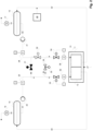
- Figure 1 depicts a simplified flow scheme of an electrolysis arrangement according to one embodiment of the invention, wherein the electrolysis arrangement is operated in mixed mode.
- the electrolysis arrangement comprises an electrolysis stack 11 to which direct current 27 with a certain current density is supplied for the water splitting electrolysis reaction within the electrolysis stack 11.
- the current density can fluctuate, for example if the electricity is generated from a renewable energy source, such as wind power.
- the electrolysis stack 11 comprises a plurality of anodes and cathodes, as well as a corresponding plurality of anode and cathode chambers.
- the plurality of anode and cathode chambers forms the anode section 12 and the cathode section 13 of the electrolysis stack 11.
- oxygen is generated by oxidation of water-bound oxygen at the anodes of the electrolysis stack 11.
- cathode section 13 hydrogen is generated by reduction of water-bound hydrogen at the cathodes of the electrolysis stack 11.
- Anodes and cathodes are physically separated by diaphragms, which enable the exchange of hydroxyl ions between the anode and the cathode section of the electrolysis stack.
- HTO hydrogen to oxygen
- the electrolysis arrangement as depicted in Figure 1 further comprises an anode pipe system, which at least comprises the pipes 40 and 41.
- an anode separator 14 is arranged within the anode separator 14.
- gaseous oxygen is physically separated from the liquid electrolyte circulating within the anode pipe system.
- the alkaline electrolyte used in the entire electrolysis system is for example highly concentrated aqueous potassium hydroxide (KOH) solution.
- KOH potassium hydroxide
- the electrolyte circulating within the anode pipe system is also referred to as the anolyte.
- the oxygen loaded anolyte is withdrawn from the anode section 12 of the electrolysis stack 11 via pipe 40, introduced into the anode separator 14 and after separation of oxygen, the oxygen depleted anolyte is withdrawn from anode separator 14 and sent to the anode section 12 of the electrolysis stack 11 to again generate oxygen by electrolysis within the electrolysis stack 11.
- Circulation of the anolyte within the anolyte pipe system is effected by pump 20. Downstream to pump 20, a flowmeter 23 is arranged. The signal taken from the flowmeter 23 can be used as a control variable to control the flow rate of the pump 20.
- the electrolysis arrangement as depicted in Figure 1 further comprises a cathode pipe system, which at least comprises the pipes 42 and 43.
- a cathode separator 15 is arranged within the cathode pipe system.
- gaseous hydrogen is physically separated from the liquid electrolyte circulating within the cathode pipe system.
- the electrolyte circulating within the cathode pipe system is also referred to as the catholyte.
- the hydrogen loaded catholyte is withdrawn from the cathode section 13 of electrolysis stack 11 via pipe 42, introduced into the cathode separator 15 and after separation of gaseous hydrogen from the liquid catholyte, the hydrogen depleted catholyte is withdrawn from cathode separator 15 and sent to the cathode section 13 of the electrolysis stack 11 to again generate hydrogen by electrolysis within the electrolysis stack 11.
- Circulation of the catholyte within the catholyte pipe system is effected by pump 21. Downstream to pump 21, a flowmeter 24 is arranged. The signal taken from the flowmeter 24 can be used as a control variable to control the flow rate of the pump 21.
- the cathode separator 15 is further equipped with a liquid level controller (not shown), which controls the liquid level of the catholyte within the cathode separator 15.
- the gaseous hydrogen product separated within cathode separator 15 is cooled via heat exchanger 17, which is supplied with cooling water (not shown). Thereby water vapour contained in the hydrogen product stream is condensed and returned to the cathode separator 15 and finally the cathode pipe system.
- the dried hydrogen product stream is withdrawn from the heat exchanger 17 via pipe 19. It is then subjected to a further processing step, e.g. a purification step.
- a water supply 22 is provided, so that water can be fed to the cathode pipe system.
- the amount of water added per unit of time by water supply 22 corresponds to the amount of water consumed per unit of time by the production of hydrogen and oxygen of the electrolysis arrangement.
- the KOH concentrations within the separated pipe systems of the electrolysis arrangement will get unbalanced as the electrolysis reaction proceeds.
- the KOH concentration within the anode pipe system (pipes 40, 41), the anode separator 14 and the anode section 12 decreases (water generation, thus dilution)
- the KOH concentration within the cathode pipe system (pipes 42, 43), the cathode separator 15 and the cathode section 13 increases (water consumption, increase of concentration).
- the water amount increases in the anode related section of the electrolysis arrangement, and the water amount decreases in the cathode related section of the electrolysis arrangement.
- the liquid levels between the anode separator 14 and the cathode separator 15 get unbalanced.
- the anolyte and catholyte can be mixed in their entirety as known from the prior art and depicted in Figure 3 .
- the anolyte withdrawn from anode separator 14 and the catholyte withdrawn from cathode separator 15 via pipe 48 and pumped by pump 29 are subsequently merged in pipe 49 and then fully mixed by static mixer 52. Downstream to the static mixer 52, the mixed electrolyte is split and separately fed to the anode section 12 and the cathode section 13 of the electrolysis stack 11.
- the electrolysis arrangement can not only be operated in a full mixed mode, but also in a separate mode (unmixed mode) without mixing the anolyte and catholyte or in a partly mixed mode with partly mixing of the anolyte and the catholyte.
- the electrolysis arrangement of Fig. 1 represents the electrolysis arrangement when it is operated in mixed mode, wherein oxygen depleted electrolyte withdrawn from anode separator 14 and hydrogen depleted electrolyte withdrawn from cathode separator 15 is fully mixed before it is supplied to the electrolysis stack.
- the electrolysis arrangement therefore comprises a first connecting pipe 44, which interconnects the pipes 41 of the anolyte pipe system and pipe 43 of the catholyte pipe system.
- First connecting pipe 44 comprises a first control valve 31.
- second control valve 32 is arranged within pipe 43 of the cathode pipe system. Second control valve 32 is closed, indicated by the black filling.
- a second part of the electrolyte is further routed to pipe 43 via a second connecting pipe 45.
- the second connecting pipe 45 comprises a third control valve 30, which is opened in the case of the operating mode, i.e. mixed mode, of the electrolysis arrangement according to the Figure 1 .
- the amount (volume flow or mass flow) of electrolyte each routed to the anode section 12 and the cathode section 13 is controlled by a fourth control valve 33 arranged within pipe 41 and a fifth control valve 34 arranged within pipe 43. Downstream to the fourth control valve 33 and the fifth control valve 34 respectively, flowmeters 25 and 26 are arranged. Signals of the flowmeters 25 and 26 can be used to control the valve lift of control valves 33 and 34, i.e. the flow rate of the electrolyte supplied to the anode section 12 and the cathode section 13 respectively.
- Figure 2 represents the same electrolysis arrangement as depicted in Figure 1 , but with the electrolysis arrangement operating in partly mixed mode, wherein oxygen depleted electrolyte withdrawn from anode separator 14 and hydrogen depleted electrolyte withdrawn from cathode separator 15 are only partly mixed before they are supplied to the electrolysis stack. In other words, they are partly mixed to the anode section 12 of the electrolysis stack 11 and the cathode section 13 of the electrolysis stack 11.
- the first control valve is closed (indicated again by black filling). Therefore, anolyte withdrawn from anode separator 14 can only be routed via pipe 41 to the anode section 12 of the electrolysis stack 11.
- Catholyte withdrawn from cathode separator 15 can only be routed via pipe 43 to the cathode section 13 of the electrolysis stack 11. No mixing of oxygen depleted anolyte withdrawn from anode separator 14 and hydrogen depleted catholyte withdrawn from cathode separator 15 occurs so far.
- the flow rate of anolyte and catholyte routed to the electrolysis stack 11 is again controlled by third control valve 33 and fourth control valve 34, respectively. However, during this mode of operation, the anolyte is slightly diluted due to generation of water in the anode section 12 of the electrolysis stack 11.
- the catholyte slightly increases in lye concentration over time due to consumption of water in the cathode section 13 of the electrolysis stack 11. Therefore, a small amount of anolyte is routed from pipe 41 via second connecting pipe 45 by means of the third control valve 45 to pipe 43 (indicated by the dotted arrows), to balance out the lye concentrations and electrolyte amounts between anolyte within pipe 41 and catholyte within pipe 43. Due to the lye concentration and lye amount balancing function of third control valve 45, no direct hydraulic link between the anode separator 14 and the cathode separator is required. Such a direct hydraulic link 28 is shown in the state of the art electrolysis arrangement according to Figure 3 .
- Hydraulic link 28 may comprise a valve and a pump to either route anolyte from the anode separator 14 to the cathode separator 15 or vice versa. It is understood by a person skilled in the art that the aforementioned mode of operation according to Fig. 2 means that only a small amount of anolyte and catholyte is mixed, before it is supplied to the anode and cathode section of the electrolysis stack. However, the flowrate passing the third control valve 45 may also be increased so that the mode of operation comes closer to operation in full mix mode.
- the electrolysis arrangement as depicted in Figures 1 and 2 may also be operated in separate mode or full separate mode. This mode is realized when the first control valve 31 and the third control valve 45 are fully closed, and the second control valve 32 is opened.
- Figure 1 and Figure 2 and the accompanying description only show examples of operating conditions, but in principle the electrolysis arrangement according to the invention can be operated, depending on the flow rate of electrolyte passing the control valves 30, 31 and 32, in the entire operating range from full separate mode to full mixed mode.
- the partly mixed mode is in particular useful to adapt the mixing rate of the electrolyte to fluctuating current densities.
- HTO crossover in the system will increase.
- the amount of mixed electrolyte supplied to the electrolysis stack can be decreased. This can be done, for example, by decreasing the electrolyte flow rate passing the third control valve 30.
- HTO crossover in the system will decrease.
- the amount of mixed electrolyte supplied to the electrolysis stack can thus be increased. This can be done by increasing the electrolyte flow rate passing the third control valve 30.
Landscapes
- Chemical & Material Sciences (AREA)
- Engineering & Computer Science (AREA)
- Chemical Kinetics & Catalysis (AREA)
- Electrochemistry (AREA)
- Materials Engineering (AREA)
- Metallurgy (AREA)
- Organic Chemistry (AREA)
- Life Sciences & Earth Sciences (AREA)
- Sustainable Development (AREA)
- Inorganic Chemistry (AREA)
- Electrolytic Production Of Non-Metals, Compounds, Apparatuses Therefor (AREA)
Claims (13)
- Elektrolyseanordnung, umfassend- einen Elektrolysestapel (11), wobeider Elektrolysestapel mit einem Gleichstrom (27) zur elektrochemischen Erzeugung von Wasserstoff und Sauerstoff aus einem alkalischen Elektrolyten versorgt wird, wobei der Gleichstrom eine Stromdichte aufweist, undder Elektrolysestapel einen Anodenabschnitt (12) und einen Kathodenabschnitt (13) umfasst,- einen Anodenabscheider (14) zur Abscheidung von Sauerstoff aus dem Elektrolyten,- einen Kathodenabscheider (15) zur Abscheidung von Wasserstoff aus dem Elektrolyten,- ein Anodenrohrsystem zur Zirkulation von Elektrolyt zwischen dem Anodenabschnitt des Elektrolysestapels und dem Anodenabscheider,- ein Kathodenrohrsystem zur Zirkulation von Elektrolyt zwischen dem Kathodenabschnitt des Elektrolysestapels und dem Kathodenabscheider,- ein erstes Verbindungsrohr (44), das das Anodenrohrsystem und das Kathodenrohrsystem miteinander verbindet, wobei innerhalb des ersten Verbindungsrohrs ein erstes Steuerventil (31) angeordnet ist,- ein zweites Steuerventil (32), das innerhalb des Anolytrohrsystems oder innerhalb des Katholytrohrsystems angeordnet ist,- ein zweites Verbindungsrohr (45), das das Anodenrohrsystem und das Kathodenrohrsystem miteinander verbindet und das stromabwärts des ersten Verbindungsrohrs, des ersten Steuerventils und des zweiten Steuerventils angeordnet ist, wobei das zweite Verbindungsrohr ein drittes Steuerventil (30) umfasst, wobei das erste Verbindungsrohr, das zweite Verbindungsrohr, das erste Steuerventil, das zweite Steuerventil und das dritte Steuerventil stromabwärts des Anodenabscheiders und des Kathodenabscheiders und stromaufwärts des Elektrolysestapels angeordnet sind, undwobei das erste Steuerventil, das zweite Steuerventil, das dritte Steuerventil, das erste Verbindungsrohr und das zweite Verbindungsrohr so konfiguriert sind, dass in Abhängigkeit von einem Elektrolytvolumenstrom, der das erste Steuerventil, das zweite Steuerventil und das dritte Steuerventil passiert, ein sauerstoffarmer Elektrolyt, der aus dem Anodenabscheider entnommen wird, und ein wasserstoffarmer Elektrolyt, der aus dem Kathodenabscheider entnommen wird, ungemischt, teilweise gemischt oder vollständig gemischt dem Anodenabschnitt des Elektrolysestapels und dem Kathodenabschnitt des Elektrolysestapels zugeführt werden.
- Elektrolyseanordnung nach Anspruch 1, wobei das zweite Steuerventil, das innerhalb des Anodenrohrsystems oder innerhalb des Kathodenrohrsystems angeordnet ist, stromabwärts des ersten Verbindungsrohrs angeordnet ist.
- Elektrolyseanordnung nach Anspruch 1 oder 2, wobei das erste Steuerventil vollständig geschlossen ist, das zweite Steuerventil geöffnet ist und das dritte Steuerventil geöffnet ist, so dass der sauerstoffarme Elektrolyt, der aus dem Anodenabscheider entnommen wird, und der wasserstoffarme Elektrolyt, der aus dem Kathodenabscheider entnommen wird, teilweise gemischt dem Anodenabschnitt des Elektrolysestapels und dem Kathodenabschnitt des Elektrolysestapels zugeführt werden.
- Elektrolyseanordnung nach Anspruch 1 oder 2, wobei das erste Steuerventil vollständig geschlossen ist, das zweite Steuerventil geöffnet ist und das dritte Steuerventil vollständig geschlossen ist, so dass der sauerstoffarme Elektrolyt, der aus dem Anodenabscheider entnommen wird, und der wasserstoffarme Elektrolyt, der aus dem Kathodenabscheider entnommen wird, ungemischt dem Anodenabschnitt des Elektrolysestapels und dem Kathodenabschnitt des Elektrolysestapels zugeführt werden.
- Elektrolyseanordnung nach Anspruch 1 oder 2, wobei das erste Steuerventil geöffnet ist, das zweite Steuerventil vollständig geschlossen ist und das dritte Steuerventil geöffnet ist, so dass der sauerstoffarme Elektrolyt, der aus dem Anodenabscheider entnommen wird, und der wasserstoffarme Elektrolyt, der aus dem Kathodenabscheider entnommen wird, vollständig gemischt dem Anodenabschnitt des Elektrolysestapels und dem Kathodenabschnitt des Elektrolysestapels zugeführt werden.
- Elektrolyseanordnung nach einem der vorhergehenden Ansprüche, wobei, wenn der sauerstoffarme Elektrolyt, der aus dem Anodenabscheider entnommen wird, und der wasserstoffarme Elektrolyt, der aus dem Kathodenabscheider entnommen wird, ungemischt, teilweise gemischt oder vollständig gemischt dem Anodenabschnitt des Elektrolysestapels und dem Kathodenabschnitt des Elektrolysestapels zugeführt werden, der Anteil des gemischten Elektrolyten- erhöht wird, wenn die Stromdichte des dem Elektrolysestapel zugeführten Gleichstroms erhöht wird, und- verringert wird, wenn die Stromdichte des dem Elektrolysestapel zugeführten Gleichstroms verringert wird.
- Elektrolyseanordnung nach einem der vorhergehenden Ansprüche, wobei, wenn dem Elektrolysestapel kein Gleichstrom zugeführt wird, so dass kein Wasserstoff und kein Sauerstoff erzeugt wird, das erste Steuerventil vollständig geschlossen ist, das zweite Steuerventil geöffnet ist und das dritte Steuerventil vollständig geschlossen ist, so dass Verbindungen zwischen dem Anodenrohrsystem und dem Kathodenrohrsystem geschlossen sind, so dass der sauerstoffarme Elektrolyt, der aus dem Anodenabscheider entnommen wird, und der wasserstoffarme Elektrolyt, der aus dem Kathodenabscheider entnommen wird, ungemischt dem Anodenabschnitt des Elektrolysestapels und dem Kathodenabschnitt des Elektrolysestapels zugeführt werden.
- Elektrolyseanordnung nach einem der vorhergehenden Ansprüche, wobei das dritte Steuerventil, das innerhalb des zweiten Verbindungsrohrs angeordnet ist, so konfiguriert ist, dass es Konzentrationsunterschiede zwischen dem Elektrolyten, der innerhalb des Anodenrohrsystems zirkuliert, und dem Elektrolyten, der innerhalb des Kathodenrohrsystems zirkuliert, ausgleicht.
- Elektrolyseanordnung nach Anspruch 8, wobei das dritte Steuerventil so konfiguriert ist, dass Elektrolyt aus dem Anodenrohrsystem entnommen und dem Kathodenrohrsystem zugeführt wird, so dass die Konzentration des innerhalb des Kathodenrohrsystems zirkulierenden Elektrolyten verringert wird.
- Elektrolyseanordnung nach einem der vorhergehenden Ansprüche, wobei die Elektrolyseanordnung keine direkte hydraulische Verbindung (28) zwischen dem Anodenabscheider und dem Kathodenabscheider umfasst.
- Elektrolyseanordnung nach einem der vorhergehenden Ansprüche, wobei innerhalb des Anodenrohrsystems ein viertes Steuerventil (33) angeordnet ist und innerhalb des Kathodenrohrsystems ein fünftes Steuerventil (34) angeordnet ist und wobei das vierte Steuerventil und das fünfte Steuerventil stromabwärts des zweiten Verbindungsrohrs und stromaufwärts des Elektrolysestapels angeordnet sind.
- Elektrolyseanordnung nach Anspruch 11, wobei das vierte und das fünfte Steuerventil so konfiguriert sind, dass sie den Elektrolytvolumenstrom steuern, der dem Anodenabschnitt des Elektrolysestapels und dem Kathodenabschnitt des Elektrolysestapels zugeführt wird.
- Elektrolyseanordnung nach Anspruch 12, wobei das vierte und das fünfte Steuerventil so konfiguriert sind, dass der Elektrolytvolumenstrom, der dem Anodenabschnitt des Elektrolysestapels zugeführt wird, und der Elektrolytvolumenstrom, der dem Kathodenabschnitt des Elektrolysestapels zugeführt wird, im Wesentlichen gleich oder gleich sind.
Priority Applications (4)
| Application Number | Priority Date | Filing Date | Title |
|---|---|---|---|
| EP21020193.5A EP4071276B1 (de) | 2021-04-09 | 2021-04-09 | Elektrolyseanordnung für die alkalische elektrolyse |
| AU2022201770A AU2022201770A1 (en) | 2021-04-09 | 2022-03-15 | Electrolysis arrangement for alkaline electrolysis |
| CN202210284331.7A CN115198292A (zh) | 2021-04-09 | 2022-03-22 | 用于碱性电解的电解装置 |
| US17/716,573 US12421611B2 (en) | 2021-04-09 | 2022-04-08 | Electrolysis arrangement for alkaline electrolysis |
Applications Claiming Priority (1)
| Application Number | Priority Date | Filing Date | Title |
|---|---|---|---|
| EP21020193.5A EP4071276B1 (de) | 2021-04-09 | 2021-04-09 | Elektrolyseanordnung für die alkalische elektrolyse |
Publications (2)
| Publication Number | Publication Date |
|---|---|
| EP4071276A1 EP4071276A1 (de) | 2022-10-12 |
| EP4071276B1 true EP4071276B1 (de) | 2025-06-04 |
Family
ID=75625287
Family Applications (1)
| Application Number | Title | Priority Date | Filing Date |
|---|---|---|---|
| EP21020193.5A Active EP4071276B1 (de) | 2021-04-09 | 2021-04-09 | Elektrolyseanordnung für die alkalische elektrolyse |
Country Status (4)
| Country | Link |
|---|---|
| US (1) | US12421611B2 (de) |
| EP (1) | EP4071276B1 (de) |
| CN (1) | CN115198292A (de) |
| AU (1) | AU2022201770A1 (de) |
Families Citing this family (4)
| Publication number | Priority date | Publication date | Assignee | Title |
|---|---|---|---|---|
| CN115961300A (zh) * | 2022-12-30 | 2023-04-14 | 大连迪创氢能源科技有限公司 | 电解制取高压氢气和氧气的系统 |
| EP4417734A1 (de) * | 2023-02-14 | 2024-08-21 | L'air Liquide, Societe Anonyme Pour L'etude Et L'exploitation Des Procedes Georges Claude | Verfahren zur regelung eines elektrolyseurs |
| NO348295B1 (en) * | 2023-09-07 | 2024-11-11 | Hystar As | A water electrolyser system and method for producing compressed hydrogen |
| EP4606932A1 (de) * | 2024-02-24 | 2025-08-27 | OÜ Stargate Hydrogen Solutions | Elektrolyseursystem und ein verfahren zum betreiben des elektrolyseursystems |
Family Cites Families (6)
| Publication number | Priority date | Publication date | Assignee | Title |
|---|---|---|---|---|
| JP4347972B2 (ja) * | 1999-11-22 | 2009-10-21 | 株式会社神鋼環境ソリューション | 水電解装置 |
| CA2435902C (en) * | 2001-02-01 | 2010-07-20 | John W. Graydon | Electrochemical cell stacks |
| CN103882466B (zh) * | 2012-12-21 | 2016-05-11 | 中国科学院大连化学物理研究所 | 一种中高压固体聚合物水电解装置 |
| JP6450636B2 (ja) * | 2015-04-20 | 2019-01-09 | デノラ・ペルメレック株式会社 | 電解方法 |
| WO2019181662A1 (ja) * | 2018-03-22 | 2019-09-26 | 株式会社トクヤマ | アルカリ水電解装置及びガス製造方法 |
| PH12021550131B1 (en) * | 2018-07-27 | 2023-12-06 | Tokuyama Corp | Gas production apparatus and gas production method |
-
2021
- 2021-04-09 EP EP21020193.5A patent/EP4071276B1/de active Active
-
2022
- 2022-03-15 AU AU2022201770A patent/AU2022201770A1/en active Pending
- 2022-03-22 CN CN202210284331.7A patent/CN115198292A/zh active Pending
- 2022-04-08 US US17/716,573 patent/US12421611B2/en active Active
Also Published As
| Publication number | Publication date |
|---|---|
| EP4071276A1 (de) | 2022-10-12 |
| CN115198292A (zh) | 2022-10-18 |
| US20220325423A1 (en) | 2022-10-13 |
| US12421611B2 (en) | 2025-09-23 |
| AU2022201770A1 (en) | 2022-10-27 |
Similar Documents
| Publication | Publication Date | Title |
|---|---|---|
| EP4071276B1 (de) | Elektrolyseanordnung für die alkalische elektrolyse | |
| US12435436B2 (en) | Electrolysis arrangement for alkaline electrolysis and method therefor | |
| US11584998B2 (en) | Electrolysis unit and electrolyser | |
| CN114134514A (zh) | 电解水制氢系统 | |
| JP2024531391A (ja) | 可変電流密度における水の電気分解方法 | |
| KR20230045915A (ko) | 암모니아 전해 시스템 및 그 제어 방법 | |
| US4305793A (en) | Method of concentrating alkali metal hydroxide in hybrid cells having cation selective membranes | |
| US20240279830A1 (en) | Process for controlling an electrolyzer | |
| CN119177458A (zh) | 一种基于质子交换膜电解槽的电解水制氢系统 | |
| US4299673A (en) | Method of concentrating alkali metal hydroxide in hybrid cells having cation selective diffusion barriers | |
| Ohiomoba et al. | Electrochemical stripping of CO2 from potassium-based salts to facilitate direct air capture | |
| CA1155487A (en) | Method of concentrating alkali metal hydroxide in hybrid cells | |
| CN222809549U (zh) | 电解水制氢系统 | |
| CN223535231U (zh) | 一种提升氧中氢纯度的电解水制氢系统 | |
| US20250354282A1 (en) | Water electrolysis process having an extended range of operation and related installation | |
| EP4606932A1 (de) | Elektrolyseursystem und ein verfahren zum betreiben des elektrolyseursystems | |
| US20250354283A1 (en) | Hydrogen and oxygen depleting system within a water electrolysis installation and related process | |
| CN120719303B (zh) | 一种含溴废水电氧化处理系统及方法 | |
| CN219547111U (zh) | 一种带有改性阳离子交换膜的过氧化氢发生装置 | |
| CN218232590U (zh) | 一种制氢系统 | |
| Scott et al. | A study of current distribution in a DEM cell during bromate formation | |
| WO2026008324A1 (en) | Electrolyser | |
| AU2023326035A1 (en) | Electrolysis device with natural circulation | |
| Gandu | Extension of dynamic operational range in alkaline water electrolysis process | |
| CN120866881A (zh) | 电解槽全工况氧中氢浓度的惰性气体稀释调节系统及方法 |
Legal Events
| Date | Code | Title | Description |
|---|---|---|---|
| PUAI | Public reference made under article 153(3) epc to a published international application that has entered the european phase |
Free format text: ORIGINAL CODE: 0009012 |
|
| STAA | Information on the status of an ep patent application or granted ep patent |
Free format text: STATUS: THE APPLICATION HAS BEEN PUBLISHED |
|
| AK | Designated contracting states |
Kind code of ref document: A1 Designated state(s): AL AT BE BG CH CY CZ DE DK EE ES FI FR GB GR HR HU IE IS IT LI LT LU LV MC MK MT NL NO PL PT RO RS SE SI SK SM TR |
|
| STAA | Information on the status of an ep patent application or granted ep patent |
Free format text: STATUS: REQUEST FOR EXAMINATION WAS MADE |
|
| 17P | Request for examination filed |
Effective date: 20230412 |
|
| RBV | Designated contracting states (corrected) |
Designated state(s): AL AT BE BG CH CY CZ DE DK EE ES FI FR GB GR HR HU IE IS IT LI LT LU LV MC MK MT NL NO PL PT RO RS SE SI SK SM TR |
|
| RAP3 | Party data changed (applicant data changed or rights of an application transferred) |
Owner name: L'AIR LIQUIDE, SOCIETE ANONYME POUR L'ETUDE ET L'EXPLOITATION DES PROCEDES GEORGES CLAUDE |
|
| GRAP | Despatch of communication of intention to grant a patent |
Free format text: ORIGINAL CODE: EPIDOSNIGR1 |
|
| STAA | Information on the status of an ep patent application or granted ep patent |
Free format text: STATUS: GRANT OF PATENT IS INTENDED |
|
| INTG | Intention to grant announced |
Effective date: 20250109 |
|
| GRAS | Grant fee paid |
Free format text: ORIGINAL CODE: EPIDOSNIGR3 |
|
| GRAA | (expected) grant |
Free format text: ORIGINAL CODE: 0009210 |
|
| STAA | Information on the status of an ep patent application or granted ep patent |
Free format text: STATUS: THE PATENT HAS BEEN GRANTED |
|
| AK | Designated contracting states |
Kind code of ref document: B1 Designated state(s): AL AT BE BG CH CY CZ DE DK EE ES FI FR GB GR HR HU IE IS IT LI LT LU LV MC MK MT NL NO PL PT RO RS SE SI SK SM TR |
|
| REG | Reference to a national code |
Ref country code: GB Ref legal event code: FG4D |
|
| REG | Reference to a national code |
Ref country code: CH Ref legal event code: EP |
|
| REG | Reference to a national code |
Ref country code: DE Ref legal event code: R096 Ref document number: 602021031564 Country of ref document: DE |
|
| REG | Reference to a national code |
Ref country code: IE Ref legal event code: FG4D |
|
| REG | Reference to a national code |
Ref country code: NL Ref legal event code: FP |
|
| PG25 | Lapsed in a contracting state [announced via postgrant information from national office to epo] |
Ref country code: ES Free format text: LAPSE BECAUSE OF FAILURE TO SUBMIT A TRANSLATION OF THE DESCRIPTION OR TO PAY THE FEE WITHIN THE PRESCRIBED TIME-LIMIT Effective date: 20250604 Ref country code: FI Free format text: LAPSE BECAUSE OF FAILURE TO SUBMIT A TRANSLATION OF THE DESCRIPTION OR TO PAY THE FEE WITHIN THE PRESCRIBED TIME-LIMIT Effective date: 20250604 |
|
| REG | Reference to a national code |
Ref country code: LT Ref legal event code: MG9D |
|
| PG25 | Lapsed in a contracting state [announced via postgrant information from national office to epo] |
Ref country code: NO Free format text: LAPSE BECAUSE OF FAILURE TO SUBMIT A TRANSLATION OF THE DESCRIPTION OR TO PAY THE FEE WITHIN THE PRESCRIBED TIME-LIMIT Effective date: 20250904 Ref country code: GR Free format text: LAPSE BECAUSE OF FAILURE TO SUBMIT A TRANSLATION OF THE DESCRIPTION OR TO PAY THE FEE WITHIN THE PRESCRIBED TIME-LIMIT Effective date: 20250905 |
|
| PG25 | Lapsed in a contracting state [announced via postgrant information from national office to epo] |
Ref country code: PL Free format text: LAPSE BECAUSE OF FAILURE TO SUBMIT A TRANSLATION OF THE DESCRIPTION OR TO PAY THE FEE WITHIN THE PRESCRIBED TIME-LIMIT Effective date: 20250604 |
|
| PG25 | Lapsed in a contracting state [announced via postgrant information from national office to epo] |
Ref country code: BG Free format text: LAPSE BECAUSE OF FAILURE TO SUBMIT A TRANSLATION OF THE DESCRIPTION OR TO PAY THE FEE WITHIN THE PRESCRIBED TIME-LIMIT Effective date: 20250604 |
|
| PG25 | Lapsed in a contracting state [announced via postgrant information from national office to epo] |
Ref country code: HR Free format text: LAPSE BECAUSE OF FAILURE TO SUBMIT A TRANSLATION OF THE DESCRIPTION OR TO PAY THE FEE WITHIN THE PRESCRIBED TIME-LIMIT Effective date: 20250604 |
|
| PG25 | Lapsed in a contracting state [announced via postgrant information from national office to epo] |
Ref country code: RS Free format text: LAPSE BECAUSE OF FAILURE TO SUBMIT A TRANSLATION OF THE DESCRIPTION OR TO PAY THE FEE WITHIN THE PRESCRIBED TIME-LIMIT Effective date: 20250904 |
|
| PG25 | Lapsed in a contracting state [announced via postgrant information from national office to epo] |
Ref country code: LV Free format text: LAPSE BECAUSE OF FAILURE TO SUBMIT A TRANSLATION OF THE DESCRIPTION OR TO PAY THE FEE WITHIN THE PRESCRIBED TIME-LIMIT Effective date: 20250604 |
|
| PG25 | Lapsed in a contracting state [announced via postgrant information from national office to epo] |
Ref country code: PT Free format text: LAPSE BECAUSE OF FAILURE TO SUBMIT A TRANSLATION OF THE DESCRIPTION OR TO PAY THE FEE WITHIN THE PRESCRIBED TIME-LIMIT Effective date: 20251006 |
|
| REG | Reference to a national code |
Ref country code: AT Ref legal event code: MK05 Ref document number: 1800404 Country of ref document: AT Kind code of ref document: T Effective date: 20250604 |
|
| PG25 | Lapsed in a contracting state [announced via postgrant information from national office to epo] |
Ref country code: IS Free format text: LAPSE BECAUSE OF FAILURE TO SUBMIT A TRANSLATION OF THE DESCRIPTION OR TO PAY THE FEE WITHIN THE PRESCRIBED TIME-LIMIT Effective date: 20251004 |
|
| PG25 | Lapsed in a contracting state [announced via postgrant information from national office to epo] |
Ref country code: AT Free format text: LAPSE BECAUSE OF FAILURE TO SUBMIT A TRANSLATION OF THE DESCRIPTION OR TO PAY THE FEE WITHIN THE PRESCRIBED TIME-LIMIT Effective date: 20250604 Ref country code: SM Free format text: LAPSE BECAUSE OF FAILURE TO SUBMIT A TRANSLATION OF THE DESCRIPTION OR TO PAY THE FEE WITHIN THE PRESCRIBED TIME-LIMIT Effective date: 20250604 |
|
| PG25 | Lapsed in a contracting state [announced via postgrant information from national office to epo] |
Ref country code: CZ Free format text: LAPSE BECAUSE OF FAILURE TO SUBMIT A TRANSLATION OF THE DESCRIPTION OR TO PAY THE FEE WITHIN THE PRESCRIBED TIME-LIMIT Effective date: 20250604 |
|
| PG25 | Lapsed in a contracting state [announced via postgrant information from national office to epo] |
Ref country code: EE Free format text: LAPSE BECAUSE OF FAILURE TO SUBMIT A TRANSLATION OF THE DESCRIPTION OR TO PAY THE FEE WITHIN THE PRESCRIBED TIME-LIMIT Effective date: 20250604 |
|
| PG25 | Lapsed in a contracting state [announced via postgrant information from national office to epo] |
Ref country code: SK Free format text: LAPSE BECAUSE OF FAILURE TO SUBMIT A TRANSLATION OF THE DESCRIPTION OR TO PAY THE FEE WITHIN THE PRESCRIBED TIME-LIMIT Effective date: 20250604 |
|
| PG25 | Lapsed in a contracting state [announced via postgrant information from national office to epo] |
Ref country code: IT Free format text: LAPSE BECAUSE OF FAILURE TO SUBMIT A TRANSLATION OF THE DESCRIPTION OR TO PAY THE FEE WITHIN THE PRESCRIBED TIME-LIMIT Effective date: 20250604 |