EP4071099A1 - Elevator door interface monitor - Google Patents
Elevator door interface monitor Download PDFInfo
- Publication number
- EP4071099A1 EP4071099A1 EP21209067.4A EP21209067A EP4071099A1 EP 4071099 A1 EP4071099 A1 EP 4071099A1 EP 21209067 A EP21209067 A EP 21209067A EP 4071099 A1 EP4071099 A1 EP 4071099A1
- Authority
- EP
- European Patent Office
- Prior art keywords
- hook
- interface
- movement
- door
- hooks
- Prior art date
- Legal status (The legal status is an assumption and is not a legal conclusion. Google has not performed a legal analysis and makes no representation as to the accuracy of the status listed.)
- Granted
Links
Images


Classifications
-
- B—PERFORMING OPERATIONS; TRANSPORTING
- B66—HOISTING; LIFTING; HAULING
- B66B—ELEVATORS; ESCALATORS OR MOVING WALKWAYS
- B66B13/00—Doors, gates, or other apparatus controlling access to, or exit from, cages or lift well landings
- B66B13/24—Safety devices in passenger lifts, not otherwise provided for, for preventing trapping of passengers
- B66B13/26—Safety devices in passenger lifts, not otherwise provided for, for preventing trapping of passengers between closing doors
-
- B—PERFORMING OPERATIONS; TRANSPORTING
- B66—HOISTING; LIFTING; HAULING
- B66B—ELEVATORS; ESCALATORS OR MOVING WALKWAYS
- B66B5/00—Applications of checking, fault-correcting, or safety devices in elevators
- B66B5/0006—Monitoring devices or performance analysers
- B66B5/0018—Devices monitoring the operating condition of the elevator system
- B66B5/0031—Devices monitoring the operating condition of the elevator system for safety reasons
-
- B—PERFORMING OPERATIONS; TRANSPORTING
- B66—HOISTING; LIFTING; HAULING
- B66B—ELEVATORS; ESCALATORS OR MOVING WALKWAYS
- B66B13/00—Doors, gates, or other apparatus controlling access to, or exit from, cages or lift well landings
- B66B13/02—Door or gate operation
- B66B13/14—Control systems or devices
-
- B—PERFORMING OPERATIONS; TRANSPORTING
- B66—HOISTING; LIFTING; HAULING
- B66B—ELEVATORS; ESCALATORS OR MOVING WALKWAYS
- B66B1/00—Control systems of elevators in general
- B66B1/34—Details, e.g. call counting devices, data transmission from car to control system, devices giving information to the control system
- B66B1/36—Means for stopping the cars, cages, or skips at predetermined levels
-
- B—PERFORMING OPERATIONS; TRANSPORTING
- B66—HOISTING; LIFTING; HAULING
- B66B—ELEVATORS; ESCALATORS OR MOVING WALKWAYS
- B66B1/00—Control systems of elevators in general
- B66B1/34—Details, e.g. call counting devices, data transmission from car to control system, devices giving information to the control system
- B66B1/46—Adaptations of switches or switchgear
- B66B1/461—Adaptations of switches or switchgear characterised by their shape or profile
-
- B—PERFORMING OPERATIONS; TRANSPORTING
- B66—HOISTING; LIFTING; HAULING
- B66B—ELEVATORS; ESCALATORS OR MOVING WALKWAYS
- B66B13/00—Doors, gates, or other apparatus controlling access to, or exit from, cages or lift well landings
- B66B13/02—Door or gate operation
- B66B13/06—Door or gate operation of sliding doors
-
- B—PERFORMING OPERATIONS; TRANSPORTING
- B66—HOISTING; LIFTING; HAULING
- B66B—ELEVATORS; ESCALATORS OR MOVING WALKWAYS
- B66B13/00—Doors, gates, or other apparatus controlling access to, or exit from, cages or lift well landings
- B66B13/30—Constructional features of doors or gates
Definitions
- Elevator cars include a cab that accommodates passengers as the elevator carries the passengers between different levels of a building.
- Typical cabs include doors that selectively open when the car is at a landing where a passenger wants to board or exit the car.
- Typical door systems include a sensor, such as a light curtain or mechanical switch, that detects when an individual or an object is between the doors and in the pathway of door movement as the doors would close. Such sensors operate to prevent the doors from closing under appropriate conditions. As long as the doors remain open, the elevator car will not leave the landing.
- An illustrative example embodiment of an elevator door interface monitor includes at least one hook having a portion that is configured to be situated across the interface and moveable responsive to contact with an item situated at least partially in the interface.
- An indicator provides an indication of an item in the interface based on movement of the hook responsive to contact with the item.
- the indicator comprises a switch that is activated responsive to the movement of the hook.
- activation of the switch results in a signal to prevent elevator car movement.
- the at least one hook comprises at least two hooks.
- a first one of the two hooks is situated to contact the item during downward elevator car movement and a second one of the two hooks is situated to contact the item during upward elevator car movement.
- the elevator door interface monitor of any of the previous paragraphs includes a link connected with the first and second hooks for coordinated movement of the two hooks.
- the coordinated movement includes movement responsive to either of the two hooks contacting the item and movement of the two hooks into a retracted position corresponding to an open door position.
- the first hook moves about a first pivot
- the second hook moves about a second pivot
- the first pivot is on a first side of the link
- the second pivot is on a second opposite side of the link
- a first direction of movement of the first hook is opposite from a second direction of movement of the second hook during the coordinated movement.
- the interface has a top near a top of an associated elevator door and a bottom near a bottom of the associated elevator door, the first hook is closer to the top of the interface than the second hook, and the second hook is closer to the bottom of the interface than the first hook.
- the at least one hook is moveable between a detecting position where the portion of the hook is situated across the interface and a retracted position where the portion of the hook can be hidden within an associated elevator door that is in an open position.
- the elevator door interface monitor of any of the previous paragraphs includes a biasing mechanism that biases the at least one hook into the retracted position.
- the portion of the at least one hook includes a blade configured to sever an item that contacts the hook during movement of an associated elevator car.
- an illustrative example embodiment of an elevator car includes the elevator door interface monitor of any of the previous paragraphs, an elevator car door having an edge situated along one side of the interface when the elevator car door is closed, a door mover assembly that moves the at least one elevator car door between open and closed positions, and a link coupling the at least one hook with a portion of the door mover to move the at least one hook into a retracted position as the door mover assembly moves the elevator car door toward the open position and to move the at least one hook into a detecting position where the portion of the hook is across the interface as the door mover assembly moves the elevator car door into the closed position.
- An illustrative example embodiment of a method of monitoring an elevator door interface includes situating a portion of at least one hook across the interface, moving at least the portion of the at least one hook responsive to contact with an item situated at least partially in the interface, and providing an indication of the item in the interface based on movement of the hook responsive to contact with the item.
- providing the indication comprises activating a switch responsive to the movement of the hook.
- activating the switch comprises generating a signal to prevent elevator car movement.
- the at least one hook comprises at least two hooks.
- a first one of the two hooks is situated to contact the item during downward elevator car movement and a second one of the two hooks is situated to contact the item during upward elevator car movement.
- the method includes coordinating movement of the two hooks including moving both of the two hooks responsive to either of the two hooks contacting the item.
- coordinating the movement includes moving the first hook in a first direction while moving the second hook in a second direction that is opposite from the first direction.
- coordinating the movement includes moving the two hooks between a detecting position where the respective portions of the hooks are situated across the interface and a retracted position where the respective portions of the hooks can be hidden within an associated elevator door that is an open position.
- the method includes biasing the two hooks into the retracted position.
- the portion of the at least one hook includes a blade configured to sever an item that contacts the hook during movement of an associated elevator car.
- FIG 1 schematically illustrates selected portions of an elevator car 20.
- a cab 22 includes elevator car doors 24 and 26. When the doors 24, 26 are closed as shown in Figure 1 , edges of the doors 24, 26 are positioned very close to each other or touch at an interface 28. While the illustrated example embodiment includes two moving doors 24, 26, some elevator cabs have only one moving door and the interface 28 exists between an edge of the door and a door jamb.
- An elevator door interface monitor 30 includes at least one hook 32, 34 and an indicator 36.
- the illustrated example embodiment includes a first hook 32 and a second hook 34.
- Each hook 32, 34 includes a portion 38 that is configured to be situated across the interface 28 where the portion 38 can contact an item situated in the interface 28.
- At least the portion 38 of the hooks 32, 34 is moveable in response to contact with an item in the interface 28.
- the indicator 36 provides an indication of an item caught in the interface in response to movement of at least one of the hooks 32, 34 which results from contact with an item in the interface 28.
- the indication from the indicator 36 may be used as a signal to prevent further movement of the elevator car 20.
- the elevator car will stop in response to the indication from the indicator 36 and return to the location or landing where the doors 24 and 26 closed prior to the indication from the indicator 36.
- the hooks 32 and 34 in the illustrated example embodiment are moveable between a detecting position shown in Figure 1 when the doors 24, 26 are closed and a retracted position shown in Figure 2 when the doors 24, 26 are open. In the retracted position, the hooks 32, 34 are hidden within the space between the elevator car door 24 and an adjacent hoistway door to which the elevator car door 24 is coupled. This feature avoids any contact with the hooks 32, 34 as passengers or items cross the threshold between the interior 40 of the elevator cab 22 and an adjacent landing.
- Figure 3 schematically shows more details of an example configuration of the elevator door interface monitor 30.
- the first hook 32 is moveable about a fist pivot 42 as schematically shown by the arrow 44.
- the second hook 34 is moveable about a second pivot 46.
- a link 50 connects the first hook 32 and the second hook 34 and establishes a connection between the hoods 32 and 34 for coordinated movement of the hooks 32 and 34.
- the link 50 is rigid and, in some embodiments, comprises a rod.
- the link 50 is connected to the first hook 32 at a first connection 52.
- the link 50 is connected to the second hook 34 at a second connection 54.
- the first pivot 42 is on a first side of the link 50 (to the right of the link according to the drawing) and the second pivot 46 is on an opposite side of the link 50 (to the left of the link according to the drawing).
- the rigidity of the link 50 and the relative positions of the first connection 52, the first pivot 42, the second connection 54 and the second pivot 46 coordinates movement of the hooks 32 and 34.
- the first hook 32 pivots about the first pivot 42 in a counterclockwise direction and the second hook 34 pivots about the second pivot 46 in a clockwise direction. If the link 50 moves down, the first hook 32 pivots about the first pivot 42 in a clockwise direction and the second hook 34 pivots about the second pivot 46 in a counterclockwise direction.
- the hooks 32 and 34 move simultaneously in opposite directions because the first and second pivots 42 and 46, respectively, are on opposite sides of the link 50.
- a coupling 56 couples the link 50 to a door mover assembly 58, which includes a motor and a belt in the illustrated example.
- a door mover assembly 58 causes movement of the doors into a closed position as shown in Figure 3
- the portion of the coupling 56 coupled to the belt is urged toward the interface 28 (to the left in the drawing) as the doors 24 and 26 reach the fully closed position.
- the coupling 56 pivots about the pivot 60 and the link 50 is urged or pushed downward and the hooks 32 and 34 pivot or rotate into the detection position with the portions 38 situated across the interface 28.
- the example embodiment of Figure 3 includes a biasing mechanism 62, such as a spring, that urges the hooks 32, 34 into the retracted position.
- a biasing mechanism 62 such as a spring
- each of the hooks 32, 34 has an associated biasing mechanism 62.
- the biasing mechanism 62 acts directly on the link 50 or the coupling 56 to urge the hooks 32, 34 into the retracted position.
- Example items that might be situated in the interface 28 when the doors 24, 26 are closed include a pet leash, a shoelace, or a strap. Even though such an item is in the interface 28, the doors 24, 26 may completely close so that the elevator car 20 may move along a hoistway (not illustrated). In some situations, it will be possible to pull such an item from the interface while the doors 24, 26 are closed. In other situations, however, such an item might be trapped in the interface 28 until the doors 24, 26 open. As the elevator car 20 moves from the landing, the trapped item will encounter one of the hooks 32, 34 and cause that hook to move in a way that will activate the indicator 36.
- Figures 4A-4C schematically illustrate a situation in which an item becomes trapped in the interface 28 with one end in the elevator cab 22 and another at the landing outside the elevator cab 22. While the doors 24, 26 are open, the first hook 32 is in the retracted position shown in Figure 4A . As the elevator door 24 reaches the closed position, the first hook 32 moves into the detection position shown in Figure 4B .
- Figure 4C illustrates a scenario in which the elevator car 20 descends after the doors 24, 26 are closed. An item 70 that is trapped in the interface will effectively be pulled up along the interface 28 because one end is in the cab 22 and the other is at the landing. As the item 70 effectively moves up along the interface 28, the item 70 eventually contacts the first hook 32. Continued downward movement of the elevator car 20 causes continued upward relative movement of the item 70 pulling the portion 38 of the first hook upward until the first hook 32 activates the indicator 36.
- the indicator 36 includes a switch that is activated based on contact with the first hook 32.
- the indication from the indicator 36 is received and interpreted by an elevator control (not illustrated) as a signal or command to stop the elevator car 20.
- the elevator control in this embodiment causes the elevator car 20 to return to the landing that it just departed from and the door mover assembly 58 causes the doors 24, 26 to open.
- the trapped item 70 can then be removed from the interface 28.
- Figure 5 illustrates a scenario in which the elevator car 20 ascends from the landing where the item 70 became trapped in the interface 28.
- the item 70 is effectively pulled downward along the interface until it contacts the second hook 34 and urges the portion 38 downward.
- the second hook 34 pivots about the second pivot 46 in a counterclockwise direction.
- the link 50 is urged upward and the first hook 32 moves in a clockwise direction until the first hook 32 contacts the switch of the indicator 36 and activates the switch.
- the coordinated movement of the first hook 32 and the second hook 34 ensures that contact between either hook 32, 34 and an item 70 trapped in the interface will result in activating the indicator 36 to stop the elevator car 20.
- the interface 28 extends along the edge of the door 24 between the top and the bottom of the door 24.
- the first hook 32 is closer to the top of the door 24 and the top of the interface 28 than the second hook 34, which is closer to the bottom than the first hook 32. Having the hooks 32, 34 situated as illustrated provides an ability to detect an item within the interface 28 regardless of which direction the elevator car 20 travels as the car 20 departs from the landing where the item became trapped in the interface 28.
- Figure 6 illustrates a feature of an example embodiment.
- a blade 72 within or attached to the portion 38 is configured to sever a trapped item as the item is urged into contact with the hook during movement of the elevator car 20.
- the second hook 34 is shown in Figure 6 as an example.
- the first hook 32 in some embodiments includes a blade 72 facing downward to sever an item that contacts the first hook 32 during movement of the elevator car.
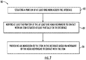
- Figure 7 is a flow chart diagram 80 that summarizes an example method of monitoring an elevator door interface, such as the interface 28.
- the method includes situating a portion 38 of at least one hook 32, 34 across the interface 28 at 82.
- the step represented at 84 includes moving at least the portion of the at least one hook 32, 34 responsive to contact with an item situated at least partially in the interface 28.
- the indicator 36 provides an indication of the item in the interface 28 based on the movement of at least the portion 38 of the hook 32, 34 responsive to contact with the item.
Landscapes
- Engineering & Computer Science (AREA)
- Automation & Control Theory (AREA)
- Computer Networks & Wireless Communication (AREA)
- Elevator Door Apparatuses (AREA)
Abstract
Description
- Elevator cars include a cab that accommodates passengers as the elevator carries the passengers between different levels of a building. Typical cabs include doors that selectively open when the car is at a landing where a passenger wants to board or exit the car. Typical door systems include a sensor, such as a light curtain or mechanical switch, that detects when an individual or an object is between the doors and in the pathway of door movement as the doors would close. Such sensors operate to prevent the doors from closing under appropriate conditions. As long as the doors remain open, the elevator car will not leave the landing.
- Even with existing door sensors, it may be possible for a relatively small item, such as a strap, to be situated on the sill or otherwise across the doorway without being detected by the sensor. In some circumstances, the doors may close on the item. If the doors are able to fully close, the elevator car will be able to move from the landing even though it is desirable or important to limit or avoid movement of the car away from the landing.
- An illustrative example embodiment of an elevator door interface monitor includes at least one hook having a portion that is configured to be situated across the interface and moveable responsive to contact with an item situated at least partially in the interface. An indicator provides an indication of an item in the interface based on movement of the hook responsive to contact with the item.
- In addition to one or more of the features described above, or as an alternative, the indicator comprises a switch that is activated responsive to the movement of the hook.
- In addition to one or more of the features described above, or as an alternative, activation of the switch results in a signal to prevent elevator car movement.
- In addition to one or more of the features described above, or as an alternative, the at least one hook comprises at least two hooks. A first one of the two hooks is situated to contact the item during downward elevator car movement and a second one of the two hooks is situated to contact the item during upward elevator car movement.
- In addition to one or more of the features described above, or as an alternative, the elevator door interface monitor of any of the previous paragraphs includes a link connected with the first and second hooks for coordinated movement of the two hooks. The coordinated movement includes movement responsive to either of the two hooks contacting the item and movement of the two hooks into a retracted position corresponding to an open door position.
- In addition to one or more of the features described above, or as an alternative, the first hook moves about a first pivot, the second hook moves about a second pivot, the first pivot is on a first side of the link, the second pivot is on a second opposite side of the link, and a first direction of movement of the first hook is opposite from a second direction of movement of the second hook during the coordinated movement.
- In addition to one or more of the features described above, or as an alternative, the interface has a top near a top of an associated elevator door and a bottom near a bottom of the associated elevator door, the first hook is closer to the top of the interface than the second hook, and the second hook is closer to the bottom of the interface than the first hook.
- In addition to one or more of the features described above, or as an alternative, the at least one hook is moveable between a detecting position where the portion of the hook is situated across the interface and a retracted position where the portion of the hook can be hidden within an associated elevator door that is in an open position.
- In addition to one or more of the features described above, or as an alternative, the elevator door interface monitor of any of the previous paragraphs includes a biasing mechanism that biases the at least one hook into the retracted position.
- In addition to one or more of the features described above, or as an alternative, the portion of the at least one hook includes a blade configured to sever an item that contacts the hook during movement of an associated elevator car.
- In addition to one or more of the features described above, or as an alternative, an illustrative example embodiment of an elevator car includes the elevator door interface monitor of any of the previous paragraphs, an elevator car door having an edge situated along one side of the interface when the elevator car door is closed, a door mover assembly that moves the at least one elevator car door between open and closed positions, and a link coupling the at least one hook with a portion of the door mover to move the at least one hook into a retracted position as the door mover assembly moves the elevator car door toward the open position and to move the at least one hook into a detecting position where the portion of the hook is across the interface as the door mover assembly moves the elevator car door into the closed position.
- An illustrative example embodiment of a method of monitoring an elevator door interface includes situating a portion of at least one hook across the interface, moving at least the portion of the at least one hook responsive to contact with an item situated at least partially in the interface, and providing an indication of the item in the interface based on movement of the hook responsive to contact with the item.
- In addition to one or more of the features described above, or as an alternative, providing the indication comprises activating a switch responsive to the movement of the hook.
- In addition to one or more of the features described above, or as an alternative, activating the switch comprises generating a signal to prevent elevator car movement.
- In addition to one or more of the features described above, or as an alternative, the at least one hook comprises at least two hooks. A first one of the two hooks is situated to contact the item during downward elevator car movement and a second one of the two hooks is situated to contact the item during upward elevator car movement.
- In addition to one or more of the features described above, or as an alternative, the method includes coordinating movement of the two hooks including moving both of the two hooks responsive to either of the two hooks contacting the item.
- In addition to one or more of the features described above, or as an alternative, coordinating the movement includes moving the first hook in a first direction while moving the second hook in a second direction that is opposite from the first direction.
- In addition to one or more of the features described above, or as an alternative, coordinating the movement includes moving the two hooks between a detecting position where the respective portions of the hooks are situated across the interface and a retracted position where the respective portions of the hooks can be hidden within an associated elevator door that is an open position.
- In addition to one or more of the features described above, or as an alternative, the method includes biasing the two hooks into the retracted position.
- In addition to one or more of the features described above, or as an alternative, the portion of the at least one hook includes a blade configured to sever an item that contacts the hook during movement of an associated elevator car.
- The various features and advantages of at least one disclosed example embodiment will become apparent to those skilled in the art from the following detailed description. The drawings that accompany the detailed description can be briefly described as follows.
-
-
Figure 1 schematically illustrates selected portions of an example embodiment of an elevator car including closed doors and a door interface monitor. -
Figure 2 schematically illustrates selected portions of the elevator car ofFigure 1 with the doors open. -
Figure 3 schematically illustrates an example embodiment of a door interface monitor. -
Figures 4A-4C schematically illustrates selected portions of the example embodiment of the door interface monitor in different conditions, respectively. -
Figure 5 schematically illustrates selected portions of the example embodiment of the door interface monitor in another condition. -
Figure 6 schematically illustrates a feature of an example embodiment of a hook used in a door interface monitor. -
Figure 7 is a flow chart diagram summarizing an example method of monitoring an elevator door interface. -
Figure 1 schematically illustrates selected portions of anelevator car 20. Acab 22 includeselevator car doors doors Figure 1 , edges of thedoors interface 28. While the illustrated example embodiment includes two movingdoors interface 28 exists between an edge of the door and a door jamb. - An elevator
door interface monitor 30 includes at least onehook indicator 36. The illustrated example embodiment includes afirst hook 32 and asecond hook 34. Eachhook portion 38 that is configured to be situated across theinterface 28 where theportion 38 can contact an item situated in theinterface 28. At least theportion 38 of thehooks interface 28. Theindicator 36 provides an indication of an item caught in the interface in response to movement of at least one of thehooks interface 28. The indication from theindicator 36 may be used as a signal to prevent further movement of theelevator car 20. In some embodiments, the elevator car will stop in response to the indication from theindicator 36 and return to the location or landing where thedoors indicator 36. - The
hooks Figure 1 when thedoors Figure 2 when thedoors hooks elevator car door 24 and an adjacent hoistway door to which theelevator car door 24 is coupled. This feature avoids any contact with thehooks elevator cab 22 and an adjacent landing. -
Figure 3 schematically shows more details of an example configuration of the elevatordoor interface monitor 30. In this example, thefirst hook 32 is moveable about afist pivot 42 as schematically shown by thearrow 44. Thesecond hook 34 is moveable about asecond pivot 46. - A
link 50 connects thefirst hook 32 and thesecond hook 34 and establishes a connection between thehoods hooks link 50 is rigid and, in some embodiments, comprises a rod. Thelink 50 is connected to thefirst hook 32 at afirst connection 52. Thelink 50 is connected to thesecond hook 34 at asecond connection 54. In the illustrated example embodiment, thefirst pivot 42 is on a first side of the link 50 (to the right of the link according to the drawing) and thesecond pivot 46 is on an opposite side of the link 50 (to the left of the link according to the drawing). The rigidity of thelink 50 and the relative positions of thefirst connection 52, thefirst pivot 42, thesecond connection 54 and thesecond pivot 46 coordinates movement of thehooks - In this embodiment, if the
link 50 moves up, thefirst hook 32 pivots about thefirst pivot 42 in a counterclockwise direction and thesecond hook 34 pivots about thesecond pivot 46 in a clockwise direction. If thelink 50 moves down, thefirst hook 32 pivots about thefirst pivot 42 in a clockwise direction and thesecond hook 34 pivots about thesecond pivot 46 in a counterclockwise direction. Thehooks second pivots link 50. - A
coupling 56 couples thelink 50 to adoor mover assembly 58, which includes a motor and a belt in the illustrated example. As thedoor mover assembly 58 causes movement of the doors into a closed position as shown inFigure 3 , the portion of thecoupling 56 coupled to the belt is urged toward the interface 28 (to the left in the drawing) as thedoors coupling 56 is urged toward theinterface 28, thecoupling 56 pivots about the pivot 60 and thelink 50 is urged or pushed downward and thehooks portions 38 situated across theinterface 28. - As the
door mover assembly 58 moves thedoors coupling 56 is urged in an opposite direction and thelink 50 is urged or pulled upward. As thelink 50 moves up, thefirst hook 32 rotates in a counterclockwise direction into the retracted position and thesecond hook 34 rotates in a clockwise direction into its retracted position. The example embodiment ofFigure 3 includes abiasing mechanism 62, such as a spring, that urges thehooks hooks biasing mechanism 62. In other embodiments, thebiasing mechanism 62 acts directly on thelink 50 or thecoupling 56 to urge thehooks - Example items that might be situated in the
interface 28 when thedoors interface 28, thedoors elevator car 20 may move along a hoistway (not illustrated). In some situations, it will be possible to pull such an item from the interface while thedoors interface 28 until thedoors elevator car 20 moves from the landing, the trapped item will encounter one of thehooks indicator 36. -
Figures 4A-4C schematically illustrate a situation in which an item becomes trapped in theinterface 28 with one end in theelevator cab 22 and another at the landing outside theelevator cab 22. While thedoors first hook 32 is in the retracted position shown inFigure 4A . As theelevator door 24 reaches the closed position, thefirst hook 32 moves into the detection position shown inFigure 4B . -
Figure 4C illustrates a scenario in which theelevator car 20 descends after thedoors item 70 that is trapped in the interface will effectively be pulled up along theinterface 28 because one end is in thecab 22 and the other is at the landing. As theitem 70 effectively moves up along theinterface 28, theitem 70 eventually contacts thefirst hook 32. Continued downward movement of theelevator car 20 causes continued upward relative movement of theitem 70 pulling theportion 38 of the first hook upward until thefirst hook 32 activates theindicator 36. - In the illustrated example embodiment, the
indicator 36 includes a switch that is activated based on contact with thefirst hook 32. The indication from theindicator 36 is received and interpreted by an elevator control (not illustrated) as a signal or command to stop theelevator car 20. The elevator control in this embodiment causes theelevator car 20 to return to the landing that it just departed from and thedoor mover assembly 58 causes thedoors item 70 can then be removed from theinterface 28. -
Figure 5 illustrates a scenario in which theelevator car 20 ascends from the landing where theitem 70 became trapped in theinterface 28. As thecar 20 moves upward, theitem 70 is effectively pulled downward along the interface until it contacts thesecond hook 34 and urges theportion 38 downward. Thesecond hook 34 pivots about thesecond pivot 46 in a counterclockwise direction. Thelink 50 is urged upward and thefirst hook 32 moves in a clockwise direction until thefirst hook 32 contacts the switch of theindicator 36 and activates the switch. - The coordinated movement of the
first hook 32 and thesecond hook 34 ensures that contact between eitherhook item 70 trapped in the interface will result in activating theindicator 36 to stop theelevator car 20. Theinterface 28 extends along the edge of thedoor 24 between the top and the bottom of thedoor 24. Thefirst hook 32 is closer to the top of thedoor 24 and the top of theinterface 28 than thesecond hook 34, which is closer to the bottom than thefirst hook 32. Having thehooks interface 28 regardless of which direction theelevator car 20 travels as thecar 20 departs from the landing where the item became trapped in theinterface 28. -
Figure 6 illustrates a feature of an example embodiment. Ablade 72 within or attached to theportion 38 is configured to sever a trapped item as the item is urged into contact with the hook during movement of theelevator car 20. Thesecond hook 34 is shown inFigure 6 as an example. Thefirst hook 32 in some embodiments includes ablade 72 facing downward to sever an item that contacts thefirst hook 32 during movement of the elevator car. -
Figure 7 is a flow chart diagram 80 that summarizes an example method of monitoring an elevator door interface, such as theinterface 28. The method includes situating aportion 38 of at least onehook interface 28 at 82. The step represented at 84 includes moving at least the portion of the at least onehook interface 28. At 86, theindicator 36 provides an indication of the item in theinterface 28 based on the movement of at least theportion 38 of thehook - The preceding description is exemplary rather than limiting in nature. Variations and modifications to the disclosed examples may become apparent to those skilled in the art that do not necessarily depart from the essence of this invention. The scope of legal protection given to this invention can only be determined by studying the following claims.
Claims (15)
- An elevator door interface monitor, comprising:at least one hook having a portion that is configured to be situated across the interface and moveable responsive to contact with an item situated at least partially in the interface; andan indicator that provides an indication of an item in the interface based on movement of the hook responsive to contact with the item.
- The elevator door interface monitor of claim 1, wherein the indicator comprises a switch that is activated responsive to the movement of the hook.
- The elevator door interface monitor of claim 2, wherein activation of the switch results in a signal to prevent elevator car movement.
- The elevator door interface monitor of claim 1, 2 or 3, whereinthe at least one hook comprises at least two hooks,a first one of the two hooks is situated to contact the item during downward elevator car movement, anda second one of the two hooks is situated to contact the item during upward elevator car movement.
- The elevator door interface monitor of claim 4, comprising a link connected with the first and second hooks for coordinated movement of the two hooks and wherein the coordinated movement includesmovement responsive to either of the two hooks contacting the item, andmovement of the two hooks into a retracted position corresponding to an open door position.
- The elevator of any preceding claim, whereinthe first hook moves about a first pivot,the second hook moves about a second pivot,the first pivot is on a first side of the link,the second pivot is on a second opposite side of the link, anda first direction of movement of the first hook is opposite from a second direction of movement of the second hook during the coordinated movement.
- The elevator door interface monitor of claim 6, whereinthe interface has a top near a top of an associated elevator door and a bottom near a bottom of the associated elevator door,the first hook is closer to the top of the interface than the second hook, andthe second hook is closer to the bottom of the interface than the first hook.
- The elevator door interface monitor of any preceding claim, wherein the at least one hook is moveable between a detecting position where the portion of the hook is situated across the interface and a retracted position where the portion of the hook can be hidden within an associated elevator door that is in an open position, optionally comprising a biasing mechanism that biases the at least one hook into the retracted position.
- The elevator door interface monitor of any preceding claim, wherein the portion of the at least one hook includes a blade configured to sever an item that contacts the hook during movement of an associated elevator car.
- An elevator car, comprising:the elevator door interface monitor of any of claims 1 to 9;an elevator car door having an edge situated along one side of the interface when the elevator car door is closed;a door mover assembly that moves the at least one elevator car door between open and closed positions; anda link coupling the at least one hook with a portion of the door mover to move the at least one hook into a retracted position as the door mover assembly moves the elevator car door toward the open position and to move the at least one hook into a detecting position where the portion of the hook is across the interface as the door mover assembly moves the elevator car door into the closed position.
- A method of monitoring an elevator door interface, the method comprising:situating a portion of at least one hook across the interface,moving at least the portion of the at least one hook responsive to contact with an item situated at least partially in the interface; andproviding an indication of the item in the interface based on movement of the hook responsive to contact with the item.
- The method of claim 11, wherein providing the indication comprises activating a switch responsive to the movement of the hook, wherein, optionally, activating the switch comprises generating a signal to prevent elevator car movement.
- The method of claim 11 or 12, whereinthe at least one hook comprises at least two hooks,a first one of the two hooks is situated to contact the item during downward elevator car movement, anda second one of the two hooks is situated to contact the item during upward elevator car movement, and / orwherein the portion of the at least one hook includes a blade configured to sever an item that contacts the hook during movement of an associated elevator car.
- The method of claim 13, comprising coordinating movement of the two hooks including moving both of the two hooks responsive to either of the two hooks contacting the item.
- The method of claim 14, wherein coordinating the movement includes moving the first hook in a first direction while moving the second hook in a second direction that is opposite from the first direction, and /or
wherein coordinating the movement includes moving the two hooks between a detecting position where the respective portions of the hooks are situated across the interface and a retracted position where the respective portions of the hooks can be hidden within an associated elevator door that is an open position, optionally comprising biasing the two hooks into the retracted position.
Applications Claiming Priority (1)
| Application Number | Priority Date | Filing Date | Title |
|---|---|---|---|
| US17/221,883 US12515917B2 (en) | 2021-04-05 | 2021-04-05 | Elevator door interface monitor |
Publications (2)
| Publication Number | Publication Date |
|---|---|
| EP4071099A1 true EP4071099A1 (en) | 2022-10-12 |
| EP4071099B1 EP4071099B1 (en) | 2024-07-10 |
Family
ID=78695606
Family Applications (1)
| Application Number | Title | Priority Date | Filing Date |
|---|---|---|---|
| EP21209067.4A Active EP4071099B1 (en) | 2021-04-05 | 2021-11-18 | Elevator door interface monitor |
Country Status (3)
| Country | Link |
|---|---|
| US (1) | US12515917B2 (en) |
| EP (1) | EP4071099B1 (en) |
| CN (1) | CN115196471B (en) |
Citations (2)
| Publication number | Priority date | Publication date | Assignee | Title |
|---|---|---|---|---|
| DE202014005758U1 (en) * | 2014-07-15 | 2014-08-12 | Markus Schneider | Protection device for lifts |
| KR101929838B1 (en) * | 2017-07-14 | 2018-12-17 | 전남대학교산학협력단 | A safety elevator equipped with a device for sensing the insertion of a pet's neck collar |
Family Cites Families (6)
| Publication number | Priority date | Publication date | Assignee | Title |
|---|---|---|---|---|
| JP4792241B2 (en) * | 2005-05-18 | 2011-10-12 | 株式会社日立製作所 | Elevator door device |
| KR20070084575A (en) * | 2007-05-25 | 2007-08-24 | 미쓰비시덴키 가부시키가이샤 | Door device of elevator |
| ES2968008T3 (en) * | 2015-08-04 | 2024-05-06 | Otis Elevator Co | Cab door interlock with threshold lock |
| US11390487B2 (en) * | 2018-08-21 | 2022-07-19 | Otis Elevator Company | Automated elevator safety chain diagnosis |
| US11767194B2 (en) * | 2019-01-28 | 2023-09-26 | Otis Elevator Company | Elevator car and door motion monitoring |
| JP6881520B2 (en) * | 2019-08-14 | 2021-06-02 | 三菱電機ビルテクノサービス株式会社 | Elevator door device |
-
2021
- 2021-04-05 US US17/221,883 patent/US12515917B2/en active Active
- 2021-11-18 EP EP21209067.4A patent/EP4071099B1/en active Active
- 2021-11-19 CN CN202111375303.8A patent/CN115196471B/en active Active
Patent Citations (2)
| Publication number | Priority date | Publication date | Assignee | Title |
|---|---|---|---|---|
| DE202014005758U1 (en) * | 2014-07-15 | 2014-08-12 | Markus Schneider | Protection device for lifts |
| KR101929838B1 (en) * | 2017-07-14 | 2018-12-17 | 전남대학교산학협력단 | A safety elevator equipped with a device for sensing the insertion of a pet's neck collar |
Also Published As
| Publication number | Publication date |
|---|---|
| US12515917B2 (en) | 2026-01-06 |
| US20220315382A1 (en) | 2022-10-06 |
| CN115196471B (en) | 2024-07-16 |
| CN115196471A (en) | 2022-10-18 |
| EP4071099B1 (en) | 2024-07-10 |
Similar Documents
| Publication | Publication Date | Title |
|---|---|---|
| CN101304939A (en) | elevator door device | |
| CN110027975B (en) | Door operation controller | |
| US10837215B2 (en) | Zone object detection system for elevator system | |
| US20230146745A1 (en) | Avoiding entrapment in an elevator | |
| US20140245664A1 (en) | Control Device for Operating an Electric Window Lifter | |
| CN109789992B (en) | elevator control circuit | |
| EP4071099B1 (en) | Elevator door interface monitor | |
| JPH05306085A (en) | Elevator door open / close inspection device | |
| CN101128388A (en) | elevator door safety device | |
| JP2006321608A (en) | Elevator door device | |
| CN107814285A (en) | A kind of control device and method for preventing accidental movement of elevator cage | |
| KR101856866B1 (en) | Optical safety sensor diagnosis system for elevator door | |
| US20200055691A1 (en) | Last-minute hall call request to a departing cab using gesture | |
| AU2019351613B2 (en) | Method and monitoring device for inferring a health status of call devices in an elevator arrangement | |
| CN110678410A (en) | Elevator device | |
| CN116553328A (en) | Elevator device | |
| JP5376842B2 (en) | Foreign object detection device for elevator | |
| CN117623069B (en) | An elevator landing door self-closing device with malfunction detection function | |
| JP7601287B2 (en) | Anomaly detection system and elevator system | |
| JP2006199389A (en) | Door device for transport aircraft | |
| JPH08232493A (en) | Vehicle position detection device for vehicle elevator | |
| US20240409368A1 (en) | Elevator system including pit safety interface | |
| WO2007084190A1 (en) | Door assembly including a brake member | |
| CN121039040A (en) | Operating system and methods for operating elevators | |
| JP2025173093A (en) | Elevator car, elevator, and elevator car manufacturing method |
Legal Events
| Date | Code | Title | Description |
|---|---|---|---|
| PUAI | Public reference made under article 153(3) epc to a published international application that has entered the european phase |
Free format text: ORIGINAL CODE: 0009012 |
|
| STAA | Information on the status of an ep patent application or granted ep patent |
Free format text: STATUS: THE APPLICATION HAS BEEN PUBLISHED |
|
| AK | Designated contracting states |
Kind code of ref document: A1 Designated state(s): AL AT BE BG CH CY CZ DE DK EE ES FI FR GB GR HR HU IE IS IT LI LT LU LV MC MK MT NL NO PL PT RO RS SE SI SK SM TR |
|
| STAA | Information on the status of an ep patent application or granted ep patent |
Free format text: STATUS: REQUEST FOR EXAMINATION WAS MADE |
|
| 17P | Request for examination filed |
Effective date: 20230331 |
|
| RBV | Designated contracting states (corrected) |
Designated state(s): AL AT BE BG CH CY CZ DE DK EE ES FI FR GB GR HR HU IE IS IT LI LT LU LV MC MK MT NL NO PL PT RO RS SE SI SK SM TR |
|
| GRAP | Despatch of communication of intention to grant a patent |
Free format text: ORIGINAL CODE: EPIDOSNIGR1 |
|
| STAA | Information on the status of an ep patent application or granted ep patent |
Free format text: STATUS: GRANT OF PATENT IS INTENDED |
|
| GRAS | Grant fee paid |
Free format text: ORIGINAL CODE: EPIDOSNIGR3 |
|
| INTG | Intention to grant announced |
Effective date: 20240216 |
|
| GRAA | (expected) grant |
Free format text: ORIGINAL CODE: 0009210 |
|
| STAA | Information on the status of an ep patent application or granted ep patent |
Free format text: STATUS: THE PATENT HAS BEEN GRANTED |
|
| AK | Designated contracting states |
Kind code of ref document: B1 Designated state(s): AL AT BE BG CH CY CZ DE DK EE ES FI FR GB GR HR HU IE IS IT LI LT LU LV MC MK MT NL NO PL PT RO RS SE SI SK SM TR |
|
| REG | Reference to a national code |
Ref country code: CH Ref legal event code: EP |
|
| REG | Reference to a national code |
Ref country code: DE Ref legal event code: R096 Ref document number: 602021015410 Country of ref document: DE |
|
| REG | Reference to a national code |
Ref country code: LT Ref legal event code: MG9D |
|
| REG | Reference to a national code |
Ref country code: NL Ref legal event code: MP Effective date: 20240710 |
|
| PG25 | Lapsed in a contracting state [announced via postgrant information from national office to epo] |
Ref country code: PT Free format text: LAPSE BECAUSE OF FAILURE TO SUBMIT A TRANSLATION OF THE DESCRIPTION OR TO PAY THE FEE WITHIN THE PRESCRIBED TIME-LIMIT Effective date: 20241111 |
|
| REG | Reference to a national code |
Ref country code: AT Ref legal event code: MK05 Ref document number: 1701911 Country of ref document: AT Kind code of ref document: T Effective date: 20240710 |
|
| PG25 | Lapsed in a contracting state [announced via postgrant information from national office to epo] |
Ref country code: NL Free format text: LAPSE BECAUSE OF FAILURE TO SUBMIT A TRANSLATION OF THE DESCRIPTION OR TO PAY THE FEE WITHIN THE PRESCRIBED TIME-LIMIT Effective date: 20240710 |
|
| PG25 | Lapsed in a contracting state [announced via postgrant information from national office to epo] |
Ref country code: PT Free format text: LAPSE BECAUSE OF FAILURE TO SUBMIT A TRANSLATION OF THE DESCRIPTION OR TO PAY THE FEE WITHIN THE PRESCRIBED TIME-LIMIT Effective date: 20241111 Ref country code: NL Free format text: LAPSE BECAUSE OF FAILURE TO SUBMIT A TRANSLATION OF THE DESCRIPTION OR TO PAY THE FEE WITHIN THE PRESCRIBED TIME-LIMIT Effective date: 20240710 |
|
| PG25 | Lapsed in a contracting state [announced via postgrant information from national office to epo] |
Ref country code: NO Free format text: LAPSE BECAUSE OF FAILURE TO SUBMIT A TRANSLATION OF THE DESCRIPTION OR TO PAY THE FEE WITHIN THE PRESCRIBED TIME-LIMIT Effective date: 20241010 |
|
| PG25 | Lapsed in a contracting state [announced via postgrant information from national office to epo] |
Ref country code: GR Free format text: LAPSE BECAUSE OF FAILURE TO SUBMIT A TRANSLATION OF THE DESCRIPTION OR TO PAY THE FEE WITHIN THE PRESCRIBED TIME-LIMIT Effective date: 20241011 Ref country code: FI Free format text: LAPSE BECAUSE OF FAILURE TO SUBMIT A TRANSLATION OF THE DESCRIPTION OR TO PAY THE FEE WITHIN THE PRESCRIBED TIME-LIMIT Effective date: 20240710 Ref country code: PL Free format text: LAPSE BECAUSE OF FAILURE TO SUBMIT A TRANSLATION OF THE DESCRIPTION OR TO PAY THE FEE WITHIN THE PRESCRIBED TIME-LIMIT Effective date: 20240710 |
|
| PG25 | Lapsed in a contracting state [announced via postgrant information from national office to epo] |
Ref country code: BG Free format text: LAPSE BECAUSE OF FAILURE TO SUBMIT A TRANSLATION OF THE DESCRIPTION OR TO PAY THE FEE WITHIN THE PRESCRIBED TIME-LIMIT Effective date: 20240710 |
|
| PG25 | Lapsed in a contracting state [announced via postgrant information from national office to epo] |
Ref country code: LV Free format text: LAPSE BECAUSE OF FAILURE TO SUBMIT A TRANSLATION OF THE DESCRIPTION OR TO PAY THE FEE WITHIN THE PRESCRIBED TIME-LIMIT Effective date: 20240710 |
|
| PG25 | Lapsed in a contracting state [announced via postgrant information from national office to epo] |
Ref country code: IS Free format text: LAPSE BECAUSE OF FAILURE TO SUBMIT A TRANSLATION OF THE DESCRIPTION OR TO PAY THE FEE WITHIN THE PRESCRIBED TIME-LIMIT Effective date: 20241110 Ref country code: AT Free format text: LAPSE BECAUSE OF FAILURE TO SUBMIT A TRANSLATION OF THE DESCRIPTION OR TO PAY THE FEE WITHIN THE PRESCRIBED TIME-LIMIT Effective date: 20240710 |
|
| PG25 | Lapsed in a contracting state [announced via postgrant information from national office to epo] |
Ref country code: HR Free format text: LAPSE BECAUSE OF FAILURE TO SUBMIT A TRANSLATION OF THE DESCRIPTION OR TO PAY THE FEE WITHIN THE PRESCRIBED TIME-LIMIT Effective date: 20240710 |
|
| PG25 | Lapsed in a contracting state [announced via postgrant information from national office to epo] |
Ref country code: ES Free format text: LAPSE BECAUSE OF FAILURE TO SUBMIT A TRANSLATION OF THE DESCRIPTION OR TO PAY THE FEE WITHIN THE PRESCRIBED TIME-LIMIT Effective date: 20240710 Ref country code: RS Free format text: LAPSE BECAUSE OF FAILURE TO SUBMIT A TRANSLATION OF THE DESCRIPTION OR TO PAY THE FEE WITHIN THE PRESCRIBED TIME-LIMIT Effective date: 20241010 |
|
| PG25 | Lapsed in a contracting state [announced via postgrant information from national office to epo] |
Ref country code: RS Free format text: LAPSE BECAUSE OF FAILURE TO SUBMIT A TRANSLATION OF THE DESCRIPTION OR TO PAY THE FEE WITHIN THE PRESCRIBED TIME-LIMIT Effective date: 20241010 Ref country code: PL Free format text: LAPSE BECAUSE OF FAILURE TO SUBMIT A TRANSLATION OF THE DESCRIPTION OR TO PAY THE FEE WITHIN THE PRESCRIBED TIME-LIMIT Effective date: 20240710 Ref country code: NO Free format text: LAPSE BECAUSE OF FAILURE TO SUBMIT A TRANSLATION OF THE DESCRIPTION OR TO PAY THE FEE WITHIN THE PRESCRIBED TIME-LIMIT Effective date: 20241010 Ref country code: LV Free format text: LAPSE BECAUSE OF FAILURE TO SUBMIT A TRANSLATION OF THE DESCRIPTION OR TO PAY THE FEE WITHIN THE PRESCRIBED TIME-LIMIT Effective date: 20240710 Ref country code: IS Free format text: LAPSE BECAUSE OF FAILURE TO SUBMIT A TRANSLATION OF THE DESCRIPTION OR TO PAY THE FEE WITHIN THE PRESCRIBED TIME-LIMIT Effective date: 20241110 Ref country code: HR Free format text: LAPSE BECAUSE OF FAILURE TO SUBMIT A TRANSLATION OF THE DESCRIPTION OR TO PAY THE FEE WITHIN THE PRESCRIBED TIME-LIMIT Effective date: 20240710 Ref country code: GR Free format text: LAPSE BECAUSE OF FAILURE TO SUBMIT A TRANSLATION OF THE DESCRIPTION OR TO PAY THE FEE WITHIN THE PRESCRIBED TIME-LIMIT Effective date: 20241011 Ref country code: FI Free format text: LAPSE BECAUSE OF FAILURE TO SUBMIT A TRANSLATION OF THE DESCRIPTION OR TO PAY THE FEE WITHIN THE PRESCRIBED TIME-LIMIT Effective date: 20240710 Ref country code: ES Free format text: LAPSE BECAUSE OF FAILURE TO SUBMIT A TRANSLATION OF THE DESCRIPTION OR TO PAY THE FEE WITHIN THE PRESCRIBED TIME-LIMIT Effective date: 20240710 Ref country code: BG Free format text: LAPSE BECAUSE OF FAILURE TO SUBMIT A TRANSLATION OF THE DESCRIPTION OR TO PAY THE FEE WITHIN THE PRESCRIBED TIME-LIMIT Effective date: 20240710 Ref country code: AT Free format text: LAPSE BECAUSE OF FAILURE TO SUBMIT A TRANSLATION OF THE DESCRIPTION OR TO PAY THE FEE WITHIN THE PRESCRIBED TIME-LIMIT Effective date: 20240710 |
|
| REG | Reference to a national code |
Ref country code: DE Ref legal event code: R097 Ref document number: 602021015410 Country of ref document: DE |
|
| PG25 | Lapsed in a contracting state [announced via postgrant information from national office to epo] |
Ref country code: RO Free format text: LAPSE BECAUSE OF FAILURE TO SUBMIT A TRANSLATION OF THE DESCRIPTION OR TO PAY THE FEE WITHIN THE PRESCRIBED TIME-LIMIT Effective date: 20240710 Ref country code: SM Free format text: LAPSE BECAUSE OF FAILURE TO SUBMIT A TRANSLATION OF THE DESCRIPTION OR TO PAY THE FEE WITHIN THE PRESCRIBED TIME-LIMIT Effective date: 20240710 Ref country code: DK Free format text: LAPSE BECAUSE OF FAILURE TO SUBMIT A TRANSLATION OF THE DESCRIPTION OR TO PAY THE FEE WITHIN THE PRESCRIBED TIME-LIMIT Effective date: 20240710 |
|
| PG25 | Lapsed in a contracting state [announced via postgrant information from national office to epo] |
Ref country code: EE Free format text: LAPSE BECAUSE OF FAILURE TO SUBMIT A TRANSLATION OF THE DESCRIPTION OR TO PAY THE FEE WITHIN THE PRESCRIBED TIME-LIMIT Effective date: 20240710 |
|
| PG25 | Lapsed in a contracting state [announced via postgrant information from national office to epo] |
Ref country code: CZ Free format text: LAPSE BECAUSE OF FAILURE TO SUBMIT A TRANSLATION OF THE DESCRIPTION OR TO PAY THE FEE WITHIN THE PRESCRIBED TIME-LIMIT Effective date: 20240710 |
|
| PG25 | Lapsed in a contracting state [announced via postgrant information from national office to epo] |
Ref country code: IT Free format text: LAPSE BECAUSE OF FAILURE TO SUBMIT A TRANSLATION OF THE DESCRIPTION OR TO PAY THE FEE WITHIN THE PRESCRIBED TIME-LIMIT Effective date: 20240710 Ref country code: SK Free format text: LAPSE BECAUSE OF FAILURE TO SUBMIT A TRANSLATION OF THE DESCRIPTION OR TO PAY THE FEE WITHIN THE PRESCRIBED TIME-LIMIT Effective date: 20240710 |
|
| PLBE | No opposition filed within time limit |
Free format text: ORIGINAL CODE: 0009261 |
|
| STAA | Information on the status of an ep patent application or granted ep patent |
Free format text: STATUS: NO OPPOSITION FILED WITHIN TIME LIMIT |
|
| 26N | No opposition filed |
Effective date: 20250411 |
|
| REG | Reference to a national code |
Ref country code: CH Ref legal event code: PL |
|
| PG25 | Lapsed in a contracting state [announced via postgrant information from national office to epo] |
Ref country code: MC Free format text: LAPSE BECAUSE OF FAILURE TO SUBMIT A TRANSLATION OF THE DESCRIPTION OR TO PAY THE FEE WITHIN THE PRESCRIBED TIME-LIMIT Effective date: 20240710 |
|
| PG25 | Lapsed in a contracting state [announced via postgrant information from national office to epo] |
Ref country code: LU Free format text: LAPSE BECAUSE OF NON-PAYMENT OF DUE FEES Effective date: 20241118 |
|
| REG | Reference to a national code |
Ref country code: CH Ref legal event code: PL |
|
| PG25 | Lapsed in a contracting state [announced via postgrant information from national office to epo] |
Ref country code: CH Free format text: LAPSE BECAUSE OF NON-PAYMENT OF DUE FEES Effective date: 20241130 |
|
| REG | Reference to a national code |
Ref country code: BE Ref legal event code: MM Effective date: 20241130 |
|
| PG25 | Lapsed in a contracting state [announced via postgrant information from national office to epo] |
Ref country code: SE Free format text: LAPSE BECAUSE OF FAILURE TO SUBMIT A TRANSLATION OF THE DESCRIPTION OR TO PAY THE FEE WITHIN THE PRESCRIBED TIME-LIMIT Effective date: 20240710 |
|
| PG25 | Lapsed in a contracting state [announced via postgrant information from national office to epo] |
Ref country code: BE Free format text: LAPSE BECAUSE OF NON-PAYMENT OF DUE FEES Effective date: 20241130 |
|
| PG25 | Lapsed in a contracting state [announced via postgrant information from national office to epo] |
Ref country code: IE Free format text: LAPSE BECAUSE OF NON-PAYMENT OF DUE FEES Effective date: 20241118 |
|
| PGFP | Annual fee paid to national office [announced via postgrant information from national office to epo] |
Ref country code: DE Payment date: 20251022 Year of fee payment: 5 |
|
| PGFP | Annual fee paid to national office [announced via postgrant information from national office to epo] |
Ref country code: FR Payment date: 20251022 Year of fee payment: 5 |
|
| PG25 | Lapsed in a contracting state [announced via postgrant information from national office to epo] |
Ref country code: HU Free format text: LAPSE BECAUSE OF FAILURE TO SUBMIT A TRANSLATION OF THE DESCRIPTION OR TO PAY THE FEE WITHIN THE PRESCRIBED TIME-LIMIT; INVALID AB INITIO Effective date: 20211118 |
|
| PG25 | Lapsed in a contracting state [announced via postgrant information from national office to epo] |
Ref country code: CY Free format text: LAPSE BECAUSE OF FAILURE TO SUBMIT A TRANSLATION OF THE DESCRIPTION OR TO PAY THE FEE WITHIN THE PRESCRIBED TIME-LIMIT; INVALID AB INITIO Effective date: 20211118 |