EP4070977A1 - Wheel unit with disengageable drive for an electric vehicle, hub unit for this wheel unit, and mounting method - Google Patents
Wheel unit with disengageable drive for an electric vehicle, hub unit for this wheel unit, and mounting method Download PDFInfo
- Publication number
- EP4070977A1 EP4070977A1 EP22156267.1A EP22156267A EP4070977A1 EP 4070977 A1 EP4070977 A1 EP 4070977A1 EP 22156267 A EP22156267 A EP 22156267A EP 4070977 A1 EP4070977 A1 EP 4070977A1
- Authority
- EP
- European Patent Office
- Prior art keywords
- wheel
- hub
- unit
- rolling bearings
- cylindrical wall
- Prior art date
- Legal status (The legal status is an assumption and is not a legal conclusion. Google has not performed a legal analysis and makes no representation as to the accuracy of the status listed.)
- Granted
Links
- 238000000034 method Methods 0.000 title claims description 4
- 238000005096 rolling process Methods 0.000 claims abstract description 38
- 125000006850 spacer group Chemical group 0.000 claims abstract description 23
- 230000008878 coupling Effects 0.000 claims abstract description 7
- 238000010168 coupling process Methods 0.000 claims abstract description 7
- 238000005859 coupling reaction Methods 0.000 claims abstract description 7
- 230000000284 resting effect Effects 0.000 claims description 2
- 238000004519 manufacturing process Methods 0.000 description 11
- XLYOFNOQVPJJNP-UHFFFAOYSA-N water Substances O XLYOFNOQVPJJNP-UHFFFAOYSA-N 0.000 description 5
- 230000008595 infiltration Effects 0.000 description 4
- 238000001764 infiltration Methods 0.000 description 4
- 230000008901 benefit Effects 0.000 description 3
- 239000004519 grease Substances 0.000 description 3
- 238000010276 construction Methods 0.000 description 2
- 238000002788 crimping Methods 0.000 description 2
- 239000007769 metal material Substances 0.000 description 2
- 239000000725 suspension Substances 0.000 description 2
- 229910000831 Steel Inorganic materials 0.000 description 1
- 230000009471 action Effects 0.000 description 1
- 239000003795 chemical substances by application Substances 0.000 description 1
- 230000009849 deactivation Effects 0.000 description 1
- 238000009434 installation Methods 0.000 description 1
- 230000001050 lubricating effect Effects 0.000 description 1
- 238000012423 maintenance Methods 0.000 description 1
- 230000009347 mechanical transmission Effects 0.000 description 1
- 230000007246 mechanism Effects 0.000 description 1
- 239000002184 metal Substances 0.000 description 1
- 230000001172 regenerating effect Effects 0.000 description 1
- 239000010959 steel Substances 0.000 description 1
Images


Classifications
-
- B—PERFORMING OPERATIONS; TRANSPORTING
- B60—VEHICLES IN GENERAL
- B60K—ARRANGEMENT OR MOUNTING OF PROPULSION UNITS OR OF TRANSMISSIONS IN VEHICLES; ARRANGEMENT OR MOUNTING OF PLURAL DIVERSE PRIME-MOVERS IN VEHICLES; AUXILIARY DRIVES FOR VEHICLES; INSTRUMENTATION OR DASHBOARDS FOR VEHICLES; ARRANGEMENTS IN CONNECTION WITH COOLING, AIR INTAKE, GAS EXHAUST OR FUEL SUPPLY OF PROPULSION UNITS IN VEHICLES
- B60K17/00—Arrangement or mounting of transmissions in vehicles
- B60K17/34—Arrangement or mounting of transmissions in vehicles for driving both front and rear wheels, e.g. four wheel drive vehicles
- B60K17/348—Arrangement or mounting of transmissions in vehicles for driving both front and rear wheels, e.g. four wheel drive vehicles having differential means for driving one set of wheels, e.g. the front, at one speed and the other set, e.g. the rear, at a different speed
- B60K17/35—Arrangement or mounting of transmissions in vehicles for driving both front and rear wheels, e.g. four wheel drive vehicles having differential means for driving one set of wheels, e.g. the front, at one speed and the other set, e.g. the rear, at a different speed including arrangements for suppressing or influencing the power transfer, e.g. viscous clutches
- B60K17/3515—Arrangement or mounting of transmissions in vehicles for driving both front and rear wheels, e.g. four wheel drive vehicles having differential means for driving one set of wheels, e.g. the front, at one speed and the other set, e.g. the rear, at a different speed including arrangements for suppressing or influencing the power transfer, e.g. viscous clutches with a clutch adjacent to traction wheel, e.g. automatic wheel hub
-
- B—PERFORMING OPERATIONS; TRANSPORTING
- B60—VEHICLES IN GENERAL
- B60K—ARRANGEMENT OR MOUNTING OF PROPULSION UNITS OR OF TRANSMISSIONS IN VEHICLES; ARRANGEMENT OR MOUNTING OF PLURAL DIVERSE PRIME-MOVERS IN VEHICLES; AUXILIARY DRIVES FOR VEHICLES; INSTRUMENTATION OR DASHBOARDS FOR VEHICLES; ARRANGEMENTS IN CONNECTION WITH COOLING, AIR INTAKE, GAS EXHAUST OR FUEL SUPPLY OF PROPULSION UNITS IN VEHICLES
- B60K17/00—Arrangement or mounting of transmissions in vehicles
- B60K17/02—Arrangement or mounting of transmissions in vehicles characterised by arrangement, location, or kind of clutch
-
- B—PERFORMING OPERATIONS; TRANSPORTING
- B60—VEHICLES IN GENERAL
- B60B—VEHICLE WHEELS; CASTORS; AXLES FOR WHEELS OR CASTORS; INCREASING WHEEL ADHESION
- B60B27/00—Hubs
- B60B27/001—Hubs with roller-bearings
-
- B—PERFORMING OPERATIONS; TRANSPORTING
- B60—VEHICLES IN GENERAL
- B60B—VEHICLE WHEELS; CASTORS; AXLES FOR WHEELS OR CASTORS; INCREASING WHEEL ADHESION
- B60B27/00—Hubs
- B60B27/0015—Hubs for driven wheels
-
- B—PERFORMING OPERATIONS; TRANSPORTING
- B60—VEHICLES IN GENERAL
- B60B—VEHICLE WHEELS; CASTORS; AXLES FOR WHEELS OR CASTORS; INCREASING WHEEL ADHESION
- B60B27/00—Hubs
- B60B27/0015—Hubs for driven wheels
- B60B27/0036—Hubs for driven wheels comprising homokinetic joints
-
- B—PERFORMING OPERATIONS; TRANSPORTING
- B60—VEHICLES IN GENERAL
- B60B—VEHICLE WHEELS; CASTORS; AXLES FOR WHEELS OR CASTORS; INCREASING WHEEL ADHESION
- B60B27/00—Hubs
- B60B27/0078—Hubs characterised by the fixation of bearings
-
- B—PERFORMING OPERATIONS; TRANSPORTING
- B60—VEHICLES IN GENERAL
- B60B—VEHICLE WHEELS; CASTORS; AXLES FOR WHEELS OR CASTORS; INCREASING WHEEL ADHESION
- B60B27/00—Hubs
- B60B27/02—Hubs adapted to be rotatably arranged on axle
-
- B—PERFORMING OPERATIONS; TRANSPORTING
- B60—VEHICLES IN GENERAL
- B60K—ARRANGEMENT OR MOUNTING OF PROPULSION UNITS OR OF TRANSMISSIONS IN VEHICLES; ARRANGEMENT OR MOUNTING OF PLURAL DIVERSE PRIME-MOVERS IN VEHICLES; AUXILIARY DRIVES FOR VEHICLES; INSTRUMENTATION OR DASHBOARDS FOR VEHICLES; ARRANGEMENTS IN CONNECTION WITH COOLING, AIR INTAKE, GAS EXHAUST OR FUEL SUPPLY OF PROPULSION UNITS IN VEHICLES
- B60K1/00—Arrangement or mounting of electrical propulsion units
-
- F—MECHANICAL ENGINEERING; LIGHTING; HEATING; WEAPONS; BLASTING
- F16—ENGINEERING ELEMENTS AND UNITS; GENERAL MEASURES FOR PRODUCING AND MAINTAINING EFFECTIVE FUNCTIONING OF MACHINES OR INSTALLATIONS; THERMAL INSULATION IN GENERAL
- F16C—SHAFTS; FLEXIBLE SHAFTS; ELEMENTS OR CRANKSHAFT MECHANISMS; ROTARY BODIES OTHER THAN GEARING ELEMENTS; BEARINGS
- F16C19/00—Bearings with rolling contact, for exclusively rotary movement
- F16C19/54—Systems consisting of a plurality of bearings with rolling friction
- F16C19/546—Systems with spaced apart rolling bearings including at least one angular contact bearing
- F16C19/547—Systems with spaced apart rolling bearings including at least one angular contact bearing with two angular contact rolling bearings
- F16C19/548—Systems with spaced apart rolling bearings including at least one angular contact bearing with two angular contact rolling bearings in O-arrangement
-
- F—MECHANICAL ENGINEERING; LIGHTING; HEATING; WEAPONS; BLASTING
- F16—ENGINEERING ELEMENTS AND UNITS; GENERAL MEASURES FOR PRODUCING AND MAINTAINING EFFECTIVE FUNCTIONING OF MACHINES OR INSTALLATIONS; THERMAL INSULATION IN GENERAL
- F16D—COUPLINGS FOR TRANSMITTING ROTATION; CLUTCHES; BRAKES
- F16D48/00—External control of clutches
- F16D48/06—Control by electric or electronic means, e.g. of fluid pressure
-
- B—PERFORMING OPERATIONS; TRANSPORTING
- B60—VEHICLES IN GENERAL
- B60B—VEHICLE WHEELS; CASTORS; AXLES FOR WHEELS OR CASTORS; INCREASING WHEEL ADHESION
- B60B2380/00—Bearings
- B60B2380/10—Type
- B60B2380/14—Roller bearings
-
- B—PERFORMING OPERATIONS; TRANSPORTING
- B60—VEHICLES IN GENERAL
- B60B—VEHICLE WHEELS; CASTORS; AXLES FOR WHEELS OR CASTORS; INCREASING WHEEL ADHESION
- B60B2380/00—Bearings
- B60B2380/70—Arrangements
-
- F—MECHANICAL ENGINEERING; LIGHTING; HEATING; WEAPONS; BLASTING
- F16—ENGINEERING ELEMENTS AND UNITS; GENERAL MEASURES FOR PRODUCING AND MAINTAINING EFFECTIVE FUNCTIONING OF MACHINES OR INSTALLATIONS; THERMAL INSULATION IN GENERAL
- F16C—SHAFTS; FLEXIBLE SHAFTS; ELEMENTS OR CRANKSHAFT MECHANISMS; ROTARY BODIES OTHER THAN GEARING ELEMENTS; BEARINGS
- F16C19/00—Bearings with rolling contact, for exclusively rotary movement
- F16C19/02—Bearings with rolling contact, for exclusively rotary movement with bearing balls essentially of the same size in one or more circular rows
- F16C19/14—Bearings with rolling contact, for exclusively rotary movement with bearing balls essentially of the same size in one or more circular rows for both radial and axial load
- F16C19/18—Bearings with rolling contact, for exclusively rotary movement with bearing balls essentially of the same size in one or more circular rows for both radial and axial load with two or more rows of balls
- F16C19/181—Bearings with rolling contact, for exclusively rotary movement with bearing balls essentially of the same size in one or more circular rows for both radial and axial load with two or more rows of balls with angular contact
- F16C19/183—Bearings with rolling contact, for exclusively rotary movement with bearing balls essentially of the same size in one or more circular rows for both radial and axial load with two or more rows of balls with angular contact with two rows at opposite angles
- F16C19/184—Bearings with rolling contact, for exclusively rotary movement with bearing balls essentially of the same size in one or more circular rows for both radial and axial load with two or more rows of balls with angular contact with two rows at opposite angles in O-arrangement
- F16C19/186—Bearings with rolling contact, for exclusively rotary movement with bearing balls essentially of the same size in one or more circular rows for both radial and axial load with two or more rows of balls with angular contact with two rows at opposite angles in O-arrangement with three raceways provided integrally on parts other than race rings, e.g. third generation hubs
-
- F—MECHANICAL ENGINEERING; LIGHTING; HEATING; WEAPONS; BLASTING
- F16—ENGINEERING ELEMENTS AND UNITS; GENERAL MEASURES FOR PRODUCING AND MAINTAINING EFFECTIVE FUNCTIONING OF MACHINES OR INSTALLATIONS; THERMAL INSULATION IN GENERAL
- F16C—SHAFTS; FLEXIBLE SHAFTS; ELEMENTS OR CRANKSHAFT MECHANISMS; ROTARY BODIES OTHER THAN GEARING ELEMENTS; BEARINGS
- F16C2326/00—Articles relating to transporting
- F16C2326/01—Parts of vehicles in general
- F16C2326/02—Wheel hubs or castors
-
- F—MECHANICAL ENGINEERING; LIGHTING; HEATING; WEAPONS; BLASTING
- F16—ENGINEERING ELEMENTS AND UNITS; GENERAL MEASURES FOR PRODUCING AND MAINTAINING EFFECTIVE FUNCTIONING OF MACHINES OR INSTALLATIONS; THERMAL INSULATION IN GENERAL
- F16D—COUPLINGS FOR TRANSMITTING ROTATION; CLUTCHES; BRAKES
- F16D11/00—Clutches in which the members have interengaging parts
- F16D2011/002—Clutches in which the members have interengaging parts using an external and axially slidable sleeve for coupling the teeth of both coupling components together
Definitions
- the present invention regards a wheel unit with disengageable drive for an electric vehicle, of the type comprising:
- BEVs battery electric vehicles
- eAWD electric All-Wheel Drive
- the four-wheel drive is in general overabundant, but is, instead, useful when the aim is to exploit as much as possible the regenerative braking capacity and consequent recharging of the battery or else for driving in limit conditions of adherence of the tyres.
- a driving axle normally the front axle
- the corresponding wheel units are provided according to the configuration referred to above.
- the member driven by the electric motor can be connected in rotation to, or else disconnected from, the wheel pin, according to the requirement of the driver, or else even automatically by the electronic controller of the vehicle, on the basis of the dynamic conditions detected. Passing from the all-wheel drive (AWD) condition to the rear-wheel drive (RWD) condition is moreover advantageous in so far as the passive resistances of the disengaged axle (axle shaft, differential, electric motor) are drastically reduced altogether to the advantage of autonomy of the vehicle battery.
- Figure 10 of the annexed drawings is a schematic cross-sectional view of a wheel unit with disengageable drive of a known type, for an electric vehicle with disengageable front-wheel drive.
- the reference number 1 designates as a whole the body of a wheel hub that is rotatably mounted via a rolling bearing 2 within a hub-supporting member 3, which is in turn rigidly connected, for example by means of bolts, to a wheel support 4.
- the reference number 5 designates a wheel pin that is carried by a driven member 6 (typically a bell-shaped body of a constant-velocity universal joint) that is to be driven in rotation by the electric motor provided for driving the front wheels of the vehicle. Since the wheel unit envisages the possibility of disengaging the connection in rotation between the driven member 6 and the wheel hub 1, the pin 5 is not rigidly connected in rotation to the wheel hub 1, as occurs in conventional solutions with permanent drive, but rather is rotatably mounted within the cylindrical wall 7 of the central opening of the wheel hub 1 by means of two rolling bearings 8, 9, axially spaced apart from each other. In this way, when the wheel hub 1 is not connected in rotation to the pin 5, and the electric driving motor is deactivated, the wheel hub 1 is free to turn around the pin 5, as in the case of any non-driving wheel.
- a driven member 6 typically a bell-shaped body of a constant-velocity universal joint
- the body of the driven member 6 and the body of the wheel hub 1 carry ring gears 10, 11, adjacent to one another, which can both be engaged by the inner toothing of a ring 12, which is carried by the driven member 6 and is axially displaceable via an actuator device (not illustrated in Figure 10 ) between an inactive position, in which it engages only the ring gear 10 of the member 6, where the wheel hub 1 is disconnected from the driven member 6, and an active position, in which the inner ring gear of the ring 12 meshes with both of the toothings of the ring gears 10, 11, so that the wheel hub 1 is connected in rotation to the driven member 6 and to the wheel pin 5.
- the front electric motor of the vehicle can be activated for driving in rotation the wheel pin 5 and therewith the wheel hub 1.
- the rolling bearings 8, 9 are stationary.
- the known solutions of the type referred to above envisage the use of a roller bearing 8, without inner ring, with the rollers directly in contact with the surface of the wheel pin 5, and a roller cage mounted within the cylindrical wall 7 of the central opening of the wheel hub 1.
- the rolling bearing 9 is a ball bearing.
- roller bearing 8 operates with a relatively wide and non-controllable functional play that is the origin of noise and/or clatter.
- a further drawback lies in the fact that the two bearings 8, 9 require an operation of adjustment that must be carried out in the production plant and that always entails the risk of it not being in all cases possible to reach the optimal operating condition of the bearings.
- a wheel unit of the type indicated at the beginning of the present description is known from WO 2006/035836 A1 .
- an object of the present invention is to provide a wheel unit of the type described above that will enable deactivation of the drive on the wheel, drastically reducing the passive resistance of the disengaged axle (axle shaft, differential, electric motor) altogether to the advantage of the autonomy of the battery of the electric vehicle, and that at the same time will overcome the drawbacks of the known solutions.
- an object of the invention is to simplify the operations to be carried out in the production plant, envisaging the possibility of preassembling (off line) a wheel-hub unit that can then be mounted with a simple operation on the wheel support in the production plant, without requiring complex operations of setting and adjustment.
- a further object of the invention is to provide a wheel unit of the type specified above that will always present proper and reliable operation.
- a further object of the invention is to provide a wheel unit of the type specified above that will not be exposed to the risk of malfunctioning on account of infiltration of water, mud or dirt.
- yet a further object of the invention is to achieve all the aforesaid aims with a wheel unit that is relatively simple and inexpensive to produce.
- the subject of the invention is a wheel unit with disengageable drive for an electric vehicle, comprising:
- the two rolling bearings are two ball bearings.
- a first ball bearing of said ball bearings which is further away from a free end of the wheel pin, has its inner ring resting against an annular shoulder of said driven member.
- a second ball bearing of said ball bearings has its inner ring that is axially fastened by a nut screwed on a threaded portion of said free end of the wheel pin, in such a way as to press the ensemble of the two inner rings of said rolling bearings, with the spacer sleeve interposed therebetween, axially against a shoulder of the driven member.
- the end of the cylindrical wall of the wheel hub that faces outwards is protected and isolated from the outside by a covering element mounted on the wheel hub.
- the unit constituted by the wheel hub, with the two aforesaid rolling bearings and with the spacer sleeve rigidly interposed between the inner rings of the two rolling bearings can be pre-assembled, off the production line, and then mounted in the production plant with a simple operation, which does not require any operation of adjustment.
- the pre-assembled unit already comprises also the grease for lubricating the bearings, without any need for further operations to be carried out in the production plant.
- the outer cover that protects the central opening of the hub prevents intrusion of external agents such as water, mud, and dirt.
- this outer cover is made of metal material in such a way as to exert also an action of protection against accidental impact and bumps.
- the aforesaid spacer sleeve is selected with a rigorously predetermined length, which is a function of the axial distance of the aforesaid annular shoulders against which the outer rings of the two rolling bearings are mounted.
- the spacer sleeve is rigidly connected, for example by means of a crimping operation, to the inner rings of the two rolling bearings, so as to be integrated in the hub unit.
- the subject of the invention is also the wheel-hub unit taken in itself, which is pre-assembled with the two rolling bearings and the spacer sleeve interposed between the inner rings of the two bearings.
- the invention also regards the method for assembling the hub unit described above, where in a first step the hub unit is assembled, with the two rolling bearings and the aforesaid spacer sleeve, and in a second step the aforesaid hub unit, assembled in the first step, is mounted on a wheel pin, axially fastening the unit in the mounted position by means of a nut screwed on the threaded end of the wheel pin in such a way as to press the ensemble of the two inner rings of the rolling bearings, with the spacer sleeve interposed therebetween, axially against a shoulder of the aforesaid driven member.
- Figure 1 shows a conventional wheel unit, where a wheel hub 1 is rotatably supported by a wheel support (steering knuckle) 4 and is permanently connected in rotation, via a constant-velocity universal joint 13, with an axle shaft 14 driven by a front electric motor of the vehicle (not illustrated).
- the example of Figure 1 refers, in fact, to a front-wheel unit, where the wheel support 4 is supported in an oscillating way about a steering axis of the wheel, by means of members of the vehicle suspension.
- the suspension members to which the wheel support 4 is connected are not illustrated, since they can be provided in any known way and also in so far as, taken in themselves, they do not fall within the scope of the present invention.
- the wheel unit according to the invention is of the type with disengageable drive for an electric vehicle that is to operate both with a first electric motor that is permanently connected to a wheel axle (typically the rear axle) and with a second electric motor that is connected in a releasable way with the hubs of the front wheels.
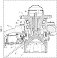
- Figure 2 shows an example of application of the invention to a wheel support 4 of a front steering wheel, with a wheel hub 1 that is rotatably supported by the wheel support 4 and a coupling device 15, described in detail in what follows, which is carried by the wheel support 4 and is provided for connecting selectively in rotation the wheel hub 1 with the driven member of the constant-velocity universal joint 13 (not illustrated in Figure 2 ), which in turn is connected to the axle shaft 14 (not illustrated in Figure 2 either).
- the wheel hub 1 is rotatably supported, by means of a double ring of balls 16, by a hub-supporting member 3, which is rigidly connected (typically by means of bolts) to the body of the wheel support 4.
- a hub-supporting member 3 which is rigidly connected (typically by means of bolts) to the body of the wheel support 4.
- the driven member 6 of the constant-velocity universal joint has a shaft constituting the wheel pin 5.
- the body of the driven member 6 and the body of the wheel hub 1 carry ring gears 10, 11 adjacent to one another that can be connected together in rotation, following upon meshing with the inner toothing, by a sliding ring 12 (see Figures 3 and 4 ).
- Figures 3 and 4 also show schematically the actuator device 15, comprising an electric motor 18 that drives, in a way in itself known, by means of a mechanical transmission of any type, axial movement of the ring 12.
- the details of construction regarding the mechanism controlled by the electric motor 18 are not described or illustrated herein both in so far as they can be obtained in any known way and in so far as, taken in themselves, they do not fall within the scope of the present invention.
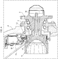
- Figure 3 shows the operating condition in which the ring 12 has its inner ring gear that meshes with both of the ring gears 10 and 11, where Figure 4 shows the operating condition in which the sleeve 12 engages only with the ring gear 10. Consequently, in the condition of Figure 3 , the driven member 6 is connected in rotation to the wheel hub 1, whereas in the condition of Figure 4 the driven member 6 is uncoupled from the wheel hub 1, which is thus free to rotate on the wheel pin 5.
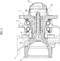
- the rotatable support of the wheel hub 1 on the wheel pin 5 is provided by means of two rolling bearings 19, 20 that in the preferred example are both ball bearings, with a single ring of balls.
- the two ball bearings 19, 20 have outer rings 19A, 20A, respectively, that are mounted bearing upon respective annular shoulders 1A, which face the opposite ends of the cylindrical wall 7 of the central opening of the wheel hub 1 and are defined by widened end portions of the aforesaid wall.
- the ball bearings 19, 20 moreover have respective inner rings 19B, 20B that are mounted on the wheel pin 5.
- Set between the inner rings 19B, 20B of the two ball bearings 19, 20 is a spacer sleeve 21, preferably made of steel, having a length rigorously predetermined as a function of the axial distance H between the two shoulders 1A, taking into account the configuration of the two bearings 19, 20.
- the length of the sleeve 21 is equal to the distance H.
- the spacer sleeve 21 is rigidly connected, for example by means of a crimping operation, to the inner rings 19B, 20B of the two bearings 19, 20, respectively. Consequently, the wheel-hub unit, designated as a whole in Figure 9 by the reference M, which includes the hub-supporting member 3, the body of the hub 1 rotatably mounted within the hub-supporting member 3 by means of the bearing including the double ring of balls 16, the two rolling bearings 19, 20, with their outer rings mounted by interference fit within the cylindrical wall 7, the inner rings and the corresponding balls, as well as with the spacer sleeve 21 rigidly connected to the inner rings of the bearings 19, 20, can be pre-assembled off line and be mounted in a single operation on the wheel pin 5 in the production plant.
- the hub unit M is axially fastened by screwing of a nut 22 on a threaded portion 5B of the wheel pin 5. Tightening of the nut 22 leads the ensemble constituted by the inner rings 19B, 20B of the two bearings 19, 20, with the spacer sleeve 21, to be pressed axially against the annular shoulder 5A of the driven member 6.
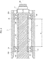
- a further important characteristic of the invention lies in the fact that rigidly mounted on the body of the hub 1 is a cover 23, which has the purpose of protecting and isolating from the outside the central opening of the hub 1, where the bearings 19 and 20 are mounted, thus preventing any infiltration of water, mud, or dirt.
- the cover 23 is made of metal material so as to perform also a function of protection against impact.
- the body of the hub 1 includes a cylindrical wall 1B projecting axially from the end surface of the hub 1 onto which the cylindrical wall 7 gives out.
- the cover 23 is in the form of a dome-shaped element made of sheet metal, with a circumferential wall 23A that is mounted by interference fit within the cylindrical wall 1B.
- any other configuration of the cover 23 is possible, just as any technique may be employed for rigidly connecting the cover 23 to the body of the hub 1 in a removable way.
Abstract
Description
- The present invention regards a wheel unit with disengageable drive for an electric vehicle, of the type comprising:
- a wheel support,
- a wheel hub rotatably supported by the wheel support,
- a wheel pin, rotatably mounted by means of two rolling bearings, which are axially spaced apart from each other, within a cylindrical wall of a central opening of the wheel hub,
- wherein the wheel pin is carried by a rotatable member configured to be driven by an electric motor of the vehicle; and
- a coupling device for releasably connecting the aforesaid driven member to the wheel hub.
- Solutions of the type referred to above have been already used in high-class battery electric vehicles (BEVs) that are equipped with two electric motors for driving respectively the front wheels and the rear wheels. In electric vehicles of this type, with four-wheel drive, the so-called eAWD (electric All-Wheel Drive), the four-wheel drive is in general overabundant, but is, instead, useful when the aim is to exploit as much as possible the regenerative braking capacity and consequent recharging of the battery or else for driving in limit conditions of adherence of the tyres. To enable engagement and disengagement of a driving axle (normally the front axle), the corresponding wheel units are provided according to the configuration referred to above. Thanks to the coupling device mentioned above, the member driven by the electric motor can be connected in rotation to, or else disconnected from, the wheel pin, according to the requirement of the driver, or else even automatically by the electronic controller of the vehicle, on the basis of the dynamic conditions detected. Passing from the all-wheel drive (AWD) condition to the rear-wheel drive (RWD) condition is moreover advantageous in so far as the passive resistances of the disengaged axle (axle shaft, differential, electric motor) are drastically reduced altogether to the advantage of autonomy of the vehicle battery.
-
Figure 10 of the annexed drawings is a schematic cross-sectional view of a wheel unit with disengageable drive of a known type, for an electric vehicle with disengageable front-wheel drive. - In
Figure 10 , thereference number 1 designates as a whole the body of a wheel hub that is rotatably mounted via a rollingbearing 2 within a hub-supportingmember 3, which is in turn rigidly connected, for example by means of bolts, to awheel support 4. - The
reference number 5 designates a wheel pin that is carried by a driven member 6 (typically a bell-shaped body of a constant-velocity universal joint) that is to be driven in rotation by the electric motor provided for driving the front wheels of the vehicle. Since the wheel unit envisages the possibility of disengaging the connection in rotation between the drivenmember 6 and thewheel hub 1, thepin 5 is not rigidly connected in rotation to thewheel hub 1, as occurs in conventional solutions with permanent drive, but rather is rotatably mounted within thecylindrical wall 7 of the central opening of thewheel hub 1 by means of tworolling bearings wheel hub 1 is not connected in rotation to thepin 5, and the electric driving motor is deactivated, thewheel hub 1 is free to turn around thepin 5, as in the case of any non-driving wheel. - To enable coupling in rotation, the body of the driven
member 6 and the body of thewheel hub 1 carryring gears ring 12, which is carried by the drivenmember 6 and is axially displaceable via an actuator device (not illustrated inFigure 10 ) between an inactive position, in which it engages only thering gear 10 of themember 6, where thewheel hub 1 is disconnected from the drivenmember 6, and an active position, in which the inner ring gear of thering 12 meshes with both of the toothings of thering gears wheel hub 1 is connected in rotation to the drivenmember 6 and to thewheel pin 5. In the latter condition, the front electric motor of the vehicle can be activated for driving in rotation thewheel pin 5 and therewith thewheel hub 1. In this condition, therolling bearings - With reference once again to
Figure 10 , the known solutions of the type referred to above that have so far been developed envisage the use of a roller bearing 8, without inner ring, with the rollers directly in contact with the surface of thewheel pin 5, and a roller cage mounted within thecylindrical wall 7 of the central opening of thewheel hub 1. The rolling bearing 9 is a ball bearing. - The known solution described above entails a series of drawbacks. In the first place, the use of a roller bearing with rollers directly in contact with the
wheel pin 5 renders the ensemble particularly exposed to malfunctioning following upon infiltration of water, mud, and dirt from outside (during installation and removal, in the production stage or during maintenance). Moreover, the roller bearing 8 operates with a relatively wide and non-controllable functional play that is the origin of noise and/or clatter. A further drawback lies in the fact that the twobearings cylindrical wall 7 facing the outside must be equipped with a specific seal against infiltration of water, mud, and dirt, with consequent increase of the passive resistance deriving from the aforesaid seal device. Once again, the entire ensemble described above also envisages application of grease in the production plant, which again leads to complications in the production stage and the risk of faults deriving from the application of an incorrect amount of grease. - In view of the foregoing, there is consequently felt the need for a solution that will overcome the drawbacks referred to above and that in particular will simplify the operations to be carried out in the production plant.
- A wheel unit of the type indicated at the beginning of the present description is known from
WO 2006/035836 A1 . - Consequently, an object of the present invention is to provide a wheel unit of the type described above that will enable deactivation of the drive on the wheel, drastically reducing the passive resistance of the disengaged axle (axle shaft, differential, electric motor) altogether to the advantage of the autonomy of the battery of the electric vehicle, and that at the same time will overcome the drawbacks of the known solutions.
- In particular, an object of the invention is to simplify the operations to be carried out in the production plant, envisaging the possibility of preassembling (off line) a wheel-hub unit that can then be mounted with a simple operation on the wheel support in the production plant, without requiring complex operations of setting and adjustment.
- A further object of the invention is to provide a wheel unit of the type specified above that will always present proper and reliable operation.
- A further object of the invention is to provide a wheel unit of the type specified above that will not be exposed to the risk of malfunctioning on account of infiltration of water, mud or dirt.
- Finally, yet a further object of the invention is to achieve all the aforesaid aims with a wheel unit that is relatively simple and inexpensive to produce.
- With a view to achieving one or more of the aforesaid objects, the subject of the invention is a wheel unit with disengageable drive for an electric vehicle, comprising:
- a wheel support,
- a wheel hub rotatably supported by the wheel support,
- a wheel pin, rotatably mounted, by means of two rolling bearings axially spaced apart from each other, within a cylindrical wall of a central opening of the wheel hub,
- wherein the wheel pin is carried by a rotatable member configured to be driven by an electric motor of the vehicle, and
- a coupling device for releasably connecting the aforesaid driven member to the wheel hub,
- the wheel pin is rotatably mounted within the cylindrical wall of the wheel hub by means of two rolling bearings axially spaced apart from each other, which have respective outer rings mounted by interference fit within said cylindrical cavity, against two respective annular shoulders of said cylindrical cavity and face the two opposite ends of the cylindrical cavity, and
- said rolling bearings have respective inner rings rigidly mounted on said wheel pin and rigidly connected together by means of a spacer sleeve having a length that is predetermined as a function of the axial distance between said annular shoulders,
- the unit consisting of said wheel hub with the rolling bearings and the spacer sleeve, being assemblable before being mounted on said wheel pin.
- In a preferred embodiment, the two rolling bearings are two ball bearings. A first ball bearing of said ball bearings, which is further away from a free end of the wheel pin, has its inner ring resting against an annular shoulder of said driven member. A second ball bearing of said ball bearings has its inner ring that is axially fastened by a nut screwed on a threaded portion of said free end of the wheel pin, in such a way as to press the ensemble of the two inner rings of said rolling bearings, with the spacer sleeve interposed therebetween, axially against a shoulder of the driven member.
- According to a further characteristic of the invention, the end of the cylindrical wall of the wheel hub that faces outwards is protected and isolated from the outside by a covering element mounted on the wheel hub.
- As emerges clearly from the foregoing, in the solution according to the invention, the unit constituted by the wheel hub, with the two aforesaid rolling bearings and with the spacer sleeve rigidly interposed between the inner rings of the two rolling bearings, can be pre-assembled, off the production line, and then mounted in the production plant with a simple operation, which does not require any operation of adjustment. The pre-assembled unit already comprises also the grease for lubricating the bearings, without any need for further operations to be carried out in the production plant.
- The outer cover that protects the central opening of the hub prevents intrusion of external agents such as water, mud, and dirt. Preferably, this outer cover is made of metal material in such a way as to exert also an action of protection against accidental impact and bumps.
- The aforesaid spacer sleeve is selected with a rigorously predetermined length, which is a function of the axial distance of the aforesaid annular shoulders against which the outer rings of the two rolling bearings are mounted.
- The spacer sleeve is rigidly connected, for example by means of a crimping operation, to the inner rings of the two rolling bearings, so as to be integrated in the hub unit. With closing of the nut that is screwed on the threaded end of the wheel pin, the unit is automatically positioned in a proper way, which minimizes the residual rolling torque of each bearing and maximizes the efficiency of the unit in terms of duration and proper and reliable operation, without any risk of noise induced by undesirable play.
- The subject of the invention is also the wheel-hub unit taken in itself, which is pre-assembled with the two rolling bearings and the spacer sleeve interposed between the inner rings of the two bearings.
- Finally, the invention also regards the method for assembling the hub unit described above, where in a first step the hub unit is assembled, with the two rolling bearings and the aforesaid spacer sleeve, and in a second step the aforesaid hub unit, assembled in the first step, is mounted on a wheel pin, axially fastening the unit in the mounted position by means of a nut screwed on the threaded end of the wheel pin in such a way as to press the ensemble of the two inner rings of the rolling bearings, with the spacer sleeve interposed therebetween, axially against a shoulder of the aforesaid driven member.
- Further characteristics and advantages of the invention will emerge from the ensuing description with reference to the annexed drawings, which are provided purely by way of non-limiting example and in which:
-
Figure 1 is a perspective view of a steering front-wheel unit of a conventional type, with a wheel support that rotatably supports a wheel hub that is permanently connected in rotation to an axle shaft driven by an electric motor of the vehicle; -
Figure 2 is a perspective view that shows a wheel support of a steering front wheel to which a preferred embodiment of the invention is applied; -
Figures 3 and4 are cross-sectional views of the preferred embodiment of the wheel unit according to the invention, in two different operating conditions; -
Figure 5 is a further cross-sectional view at an enlarged scale of the wheel unit ofFigures 3 and4 ; -
Figure 6 is a further cross-sectional view at an enlarged scale of a detail ofFigure 5 ; -
Figures 7 and 8 are two perspective views of the hub unit according to the invention; -
Figure 9 is a cross-sectional view of the hub unit ofFigures 7 and 8 ; and -
Figure 10 is a partial schematic cross-sectional view of a wheel unit according to the prior art. - In
Figures 1-9 , the parts that are in common or correspond to the ones illustrated inFigure 10 , regarding the prior art already described above, are designated by the same reference numbers. -
Figure 1 shows a conventional wheel unit, where awheel hub 1 is rotatably supported by a wheel support (steering knuckle) 4 and is permanently connected in rotation, via a constant-velocityuniversal joint 13, with anaxle shaft 14 driven by a front electric motor of the vehicle (not illustrated). The example ofFigure 1 refers, in fact, to a front-wheel unit, where thewheel support 4 is supported in an oscillating way about a steering axis of the wheel, by means of members of the vehicle suspension. Both inFigure 1 and inFigures 2-9 that regard the preferred embodiment of the invention, the suspension members to which thewheel support 4 is connected are not illustrated, since they can be provided in any known way and also in so far as, taken in themselves, they do not fall within the scope of the present invention. - As already mentioned above, the wheel unit according to the invention is of the type with disengageable drive for an electric vehicle that is to operate both with a first electric motor that is permanently connected to a wheel axle (typically the rear axle) and with a second electric motor that is connected in a releasable way with the hubs of the front wheels.
-
Figure 2 shows an example of application of the invention to awheel support 4 of a front steering wheel, with awheel hub 1 that is rotatably supported by thewheel support 4 and acoupling device 15, described in detail in what follows, which is carried by thewheel support 4 and is provided for connecting selectively in rotation thewheel hub 1 with the driven member of the constant-velocity universal joint 13 (not illustrated inFigure 2 ), which in turn is connected to the axle shaft 14 (not illustrated inFigure 2 either). - With reference to
Figures 3 ,4 , and5 , in the example of embodiment illustrated here, thewheel hub 1 is rotatably supported, by means of a double ring ofballs 16, by a hub-supportingmember 3, which is rigidly connected (typically by means of bolts) to the body of thewheel support 4. It should be noted that the specific configuration of thewheel support 4, of the hub-supportingmember 3, of the body of thewheel hub 1, as well as of the rolling bearing constituted by the double ring ofballs 16, is here illustrated purely by way of example, these components possibly being provided in any other known way. - The driven
member 6 of the constant-velocity universal joint has a shaft constituting thewheel pin 5. As in the case of the known solution illustrated inFigure 10 , the body of the drivenmember 6 and the body of thewheel hub 1 carry ring gears 10, 11 adjacent to one another that can be connected together in rotation, following upon meshing with the inner toothing, by a sliding ring 12 (seeFigures 3 and4 ).Figures 3 and4 also show schematically theactuator device 15, comprising anelectric motor 18 that drives, in a way in itself known, by means of a mechanical transmission of any type, axial movement of thering 12. The details of construction regarding the mechanism controlled by theelectric motor 18 are not described or illustrated herein both in so far as they can be obtained in any known way and in so far as, taken in themselves, they do not fall within the scope of the present invention. -
Figure 3 shows the operating condition in which thering 12 has its inner ring gear that meshes with both of the ring gears 10 and 11, whereFigure 4 shows the operating condition in which thesleeve 12 engages only with thering gear 10. Consequently, in the condition ofFigure 3 , the drivenmember 6 is connected in rotation to thewheel hub 1, whereas in the condition ofFigure 4 the drivenmember 6 is uncoupled from thewheel hub 1, which is thus free to rotate on thewheel pin 5. - With reference in particular to
Figures 5 and6 , the rotatable support of thewheel hub 1 on thewheel pin 5 is provided by means of two rollingbearings ball bearings outer rings annular shoulders 1A, which face the opposite ends of thecylindrical wall 7 of the central opening of thewheel hub 1 and are defined by widened end portions of the aforesaid wall. - The
ball bearings inner rings wheel pin 5. - Set between the
inner rings ball bearings spacer sleeve 21, preferably made of steel, having a length rigorously predetermined as a function of the axial distance H between the twoshoulders 1A, taking into account the configuration of the twobearings sleeve 21 is equal to the distance H. - The
spacer sleeve 21 is rigidly connected, for example by means of a crimping operation, to theinner rings bearings Figure 9 by the reference M, which includes the hub-supportingmember 3, the body of thehub 1 rotatably mounted within the hub-supportingmember 3 by means of the bearing including the double ring ofballs 16, the two rollingbearings cylindrical wall 7, the inner rings and the corresponding balls, as well as with thespacer sleeve 21 rigidly connected to the inner rings of thebearings wheel pin 5 in the production plant. During the above mounting step, the twobearings spacer sleeve 21 are fitted on thewheel pin 5 until the rollingbearing 19 that is further away from the free end of thewheel pin 5 is brought up against anannular shoulder 5A (Figure 6 ) defined by a portion of enlarged diameter of the pin 5 (Figure 6 ).Figures 7 and 8 show two perspective views of the hub unit M ofFigure 9 , before it is mounted on the wheel pin. - With reference once again to
Figure 6 , once the hub unit M has been mounted on thewheel pin 5, it is axially fastened by screwing of anut 22 on a threadedportion 5B of thewheel pin 5. Tightening of thenut 22 leads the ensemble constituted by theinner rings bearings spacer sleeve 21, to be pressed axially against theannular shoulder 5A of the drivenmember 6. - Consequently, the final operation of mounting of the hub unit can be carried out in a fast and efficient way, with the assurance of obtaining proper operation of the wheel unit, without any need for complex operations of adjustment.
- A further important characteristic of the invention lies in the fact that rigidly mounted on the body of the
hub 1 is acover 23, which has the purpose of protecting and isolating from the outside the central opening of thehub 1, where thebearings cover 23 is made of metal material so as to perform also a function of protection against impact. - In the example illustrated (see
Figure 5 ), the body of thehub 1 includes acylindrical wall 1B projecting axially from the end surface of thehub 1 onto which thecylindrical wall 7 gives out. Once again in this example, thecover 23 is in the form of a dome-shaped element made of sheet metal, with acircumferential wall 23A that is mounted by interference fit within thecylindrical wall 1B. Of course, any other configuration of thecover 23 is possible, just as any technique may be employed for rigidly connecting thecover 23 to the body of thehub 1 in a removable way. - Of course, without prejudice to the principle of the invention, the details of construction and the embodiments may vary widely with respect to what has been described and illustrated herein purely by way of example, without thereby departing from the scope of the present invention, as defined in the annexed claims.
Claims (6)
- A wheel unit with disengageable drive for an electric vehicle, comprising:- a wheel support (4),- a wheel hub (1) rotatably supported by the wheel support (4),- a wheel pin (5) rotatably mounted, by means of two rolling bearings (19, 20) axially spaced apart from each other, within a cylindrical wall (7) of a central opening of the wheel hub (1),- wherein the wheel pin (5) is carried by a rotatable member (6) configured to be driven by an electric motor of the vehicle, and- a coupling device (15) for releasably connecting said driven member (6) to the wheel hub (1),said wheel unit being characterized in that:- the wheel pin (5) is rotatably mounted within the cylindrical wall (7) of the wheel hub (1) by means of two rolling bearings (19, 20) that are axially spaced apart from each other and have respective outer rings (19A, 20A) mounted by interference fit within said cylindrical wall (7), against two respective annular shoulders (1A) of said cylindrical wall (7) that face the two opposite ends of the cylindrical wall (7), and- said rolling bearings (19, 20) having respective inner rings (19B, 20B) rigidly mounted on said wheel pin (5) and rigidly connected together by means of a spacer sleeve (21) having a length predetermined as a function of the axial distance (H) between said annular shoulders (1A),- the unit (M) consisting of said wheel hub (1) with said rolling bearings (19, 20) and said spacer sleeve (21), being assemblable before being mounted on said wheel pin (5).
- The wheel unit according to claim 1, characterized in that said rolling bearings (19, 20) are ball bearings, in that a first ball bearing (19) of said ball bearings, which is further away from a free end of the wheel pin (5) has its inner ring (19B) resting against an annular shoulder (5A) of said driven member (6), and in that a second ball bearing (20) of said ball bearings has its inner ring (20B) that is axially fastened by a nut (22) screwed on a threaded portion (5B) of the free end of said wheel pin (5) so as to press axially the ensemble of the two inner rings (19B, 20B) of said rolling bearings, with the spacer sleeve (21) interposed therebetween, against said shoulder (5B) of the driven member (6).
- The wheel unit according to claim 1, characterized in that the end of the cylindrical wall (7) of the central opening of the wheel hub (1) that faces outwards is protected and isolated from the outside by a covering element (23) rigidly connected to the wheel hub (1).
- A wheel-hub unit (M), for a wheel unit with disengageable drive according to any one of the preceding claims, comprising:- a hub-supporting member (3) configured to be rigidly connected on a wheel support (4), and- a wheel hub (1) rotatably supported by said hub-supporting member (3), and having a central opening with a cylindrical wall (7) which is configured to receive and rotatably support a wheel pin (5) carried by a driven member (6),said wheel-hub unit (M) being characterized in that:- two rolling bearings (19, 20) axially spaced apart from each other are assembled within the cylindrical wall (7) of the central opening of the wheel hub (1),- the two rolling bearings (19, 20) have respective outer rings mounted by interference fit within said cylindrical wall (7) against two respective annular shoulders (1A) of said cylindrical wall that face the two opposite ends of the cylindrical wall (7), and- said rolling bearings (19, 20) have respective inner rings (19B, 20B) rigidly connected together by means of a spacer sleeve (21) having a length that is predetermined as a function of the axial distance (H) between said annular shoulders (1A),- said wheel-hub unit (M), with said rolling bearings (19, 20) and said spacer sleeve (21), being configured to be assemblable on said wheel pin (5).
- The wheel-hub unit (M) according to claim 4, characterized in that the end of the cylindrical wall (7) of the central opening of the wheel hub (1) that faces outwards is protected and isolated from the outside by a covering element (23) rigidly mounted on the wheel hub (1).
- A method for mounting a wheel-hub unit (M) according to claim 4 on a wheel pin (5), characterized in that in a first step said wheel-hub unit (M) is assembled, with the inclusion therein of said rolling bearings (19, 20) and said spacer sleeve (21), and in a second step said wheel-hub unit (M) that has been assembled in the first step is mounted on a wheel pin (5), axially fastening the hub unit (M) in the mounted position by means of a nut (22) screwed on a threaded end (5B) of the wheel pin (5), so as to press axially the ensemble of the two inner rings (19B, 20B) of said rolling bearings (19, 20), with the spacer sleeve (21) interposed therebetween, against a shoulder (5A) of said driven member (6).
Applications Claiming Priority (1)
| Application Number | Priority Date | Filing Date | Title |
|---|---|---|---|
| IT102021000008579A IT202100008579A1 (en) | 2021-04-07 | 2021-04-07 | "WHEEL ASSEMBLY, WITH DISENGAGEABLE DRIVE, FOR AN ELECTRIC VEHICLE, HUB ASSEMBLY FOR THIS WHEEL ASSEMBLY, AND ASSEMBLY PROCEDURE" |
Publications (2)
| Publication Number | Publication Date |
|---|---|
| EP4070977A1 true EP4070977A1 (en) | 2022-10-12 |
| EP4070977B1 EP4070977B1 (en) | 2023-09-13 |
Family
ID=77021754
Family Applications (1)
| Application Number | Title | Priority Date | Filing Date |
|---|---|---|---|
| EP22156267.1A Active EP4070977B1 (en) | 2021-04-07 | 2022-02-11 | Wheel unit with disengageable drive for an electric vehicle, hub unit for this wheel unit, and mounting method |
Country Status (5)
| Country | Link |
|---|---|
| US (1) | US11535098B2 (en) |
| EP (1) | EP4070977B1 (en) |
| CN (1) | CN115195342A (en) |
| BR (1) | BR102022002551A2 (en) |
| IT (1) | IT202100008579A1 (en) |
Families Citing this family (1)
| Publication number | Priority date | Publication date | Assignee | Title |
|---|---|---|---|---|
| US11691612B2 (en) * | 2021-02-12 | 2023-07-04 | Dana Heavy Vehicle Systems Group, Llc | Systems and methods for disconnecting tandem axles |
Citations (4)
| Publication number | Priority date | Publication date | Assignee | Title |
|---|---|---|---|---|
| US6170628B1 (en) * | 1996-05-22 | 2001-01-09 | Warn Industries, Inc. | Vehicle drive train |
| WO2006035836A1 (en) | 2004-09-30 | 2006-04-06 | Jtekt Corporation | Hub unit, rolling bearing device, producing method for rolling bearing device, and assembling device and assembling method for rolling bearing device |
| US8047724B2 (en) * | 2006-03-28 | 2011-11-01 | Jtekt Corporation | Bearing device for wheel |
| JP2012218490A (en) * | 2011-04-05 | 2012-11-12 | Ntn Corp | Bearing device for wheel |
Family Cites Families (1)
| Publication number | Priority date | Publication date | Assignee | Title |
|---|---|---|---|---|
| US9382951B2 (en) * | 2014-09-05 | 2016-07-05 | Warn Industries, Inc. | Locking hub system |
-
2021
- 2021-04-07 IT IT102021000008579A patent/IT202100008579A1/en unknown
-
2022
- 2022-02-10 BR BR102022002551-7A patent/BR102022002551A2/en unknown
- 2022-02-11 EP EP22156267.1A patent/EP4070977B1/en active Active
- 2022-04-05 US US17/713,322 patent/US11535098B2/en active Active
- 2022-04-07 CN CN202210359597.3A patent/CN115195342A/en active Pending
Patent Citations (4)
| Publication number | Priority date | Publication date | Assignee | Title |
|---|---|---|---|---|
| US6170628B1 (en) * | 1996-05-22 | 2001-01-09 | Warn Industries, Inc. | Vehicle drive train |
| WO2006035836A1 (en) | 2004-09-30 | 2006-04-06 | Jtekt Corporation | Hub unit, rolling bearing device, producing method for rolling bearing device, and assembling device and assembling method for rolling bearing device |
| US8047724B2 (en) * | 2006-03-28 | 2011-11-01 | Jtekt Corporation | Bearing device for wheel |
| JP2012218490A (en) * | 2011-04-05 | 2012-11-12 | Ntn Corp | Bearing device for wheel |
Also Published As
| Publication number | Publication date |
|---|---|
| CN115195342A (en) | 2022-10-18 |
| IT202100008579A1 (en) | 2022-10-07 |
| US20220324320A1 (en) | 2022-10-13 |
| EP4070977B1 (en) | 2023-09-13 |
| BR102022002551A2 (en) | 2022-10-11 |
| US11535098B2 (en) | 2022-12-27 |
Similar Documents
| Publication | Publication Date | Title |
|---|---|---|
| US6170628B1 (en) | Vehicle drive train | |
| US6676226B2 (en) | Wheel end system | |
| KR100373168B1 (en) | Integrated wheel end system | |
| US6863634B2 (en) | Tandem axle power divider assembly with inboard slip driveshaft connection | |
| US6254196B1 (en) | Axle hub assembly with removable axle shaft | |
| US5141088A (en) | Hub clutch device | |
| US8047724B2 (en) | Bearing device for wheel | |
| JPH0151369B2 (en) | ||
| US5941335A (en) | Integral wheel end assembly | |
| EP4070977B1 (en) | Wheel unit with disengageable drive for an electric vehicle, hub unit for this wheel unit, and mounting method | |
| US6318533B1 (en) | Motor vehicle wheel end assembly with hub lock | |
| US6079512A (en) | Motor vehicle wheel end assembly | |
| US5702162A (en) | Live spindle four wheel drive motor vehicle wheel end assembly | |
| US7073874B1 (en) | Vehicle drive | |
| US5494129A (en) | Insertable unit for a bearing assembly | |
| US6336537B1 (en) | Wheel end with bi-directional overrunning clutch | |
| US20080063335A1 (en) | Rolling Bearing Assembly | |
| US6557947B1 (en) | Three quarter floating automotive axle | |
| JP2000198459A (en) | Integrated wheel end assembly | |
| US6918637B2 (en) | Wheel end system | |
| WO2023199365A1 (en) | Wheel unit with disengageable drive for an electric vehicle | |
| WO2004009392A1 (en) | Inter-axle differential having improved bearing arrangement | |
| US4343205A (en) | Differential | |
| JP4024983B2 (en) | Wheel bearing device | |
| JP2539563Y2 (en) | Automotive wheel bearing device |
Legal Events
| Date | Code | Title | Description |
|---|---|---|---|
| PUAI | Public reference made under article 153(3) epc to a published international application that has entered the european phase |
Free format text: ORIGINAL CODE: 0009012 |
|
| STAA | Information on the status of an ep patent application or granted ep patent |
Free format text: STATUS: THE APPLICATION HAS BEEN PUBLISHED |
|
| AK | Designated contracting states |
Kind code of ref document: A1 Designated state(s): AL AT BE BG CH CY CZ DE DK EE ES FI FR GB GR HR HU IE IS IT LI LT LU LV MC MK MT NL NO PL PT RO RS SE SI SK SM TR |
|
| STAA | Information on the status of an ep patent application or granted ep patent |
Free format text: STATUS: REQUEST FOR EXAMINATION WAS MADE |
|
| 17P | Request for examination filed |
Effective date: 20230214 |
|
| RBV | Designated contracting states (corrected) |
Designated state(s): AL AT BE BG CH CY CZ DE DK EE ES FI FR GB GR HR HU IE IS IT LI LT LU LV MC MK MT NL NO PL PT RO RS SE SI SK SM TR |
|
| GRAP | Despatch of communication of intention to grant a patent |
Free format text: ORIGINAL CODE: EPIDOSNIGR1 |
|
| STAA | Information on the status of an ep patent application or granted ep patent |
Free format text: STATUS: GRANT OF PATENT IS INTENDED |
|
| INTG | Intention to grant announced |
Effective date: 20230504 |
|
| GRAS | Grant fee paid |
Free format text: ORIGINAL CODE: EPIDOSNIGR3 |
|
| GRAA | (expected) grant |
Free format text: ORIGINAL CODE: 0009210 |
|
| STAA | Information on the status of an ep patent application or granted ep patent |
Free format text: STATUS: THE PATENT HAS BEEN GRANTED |
|
| AK | Designated contracting states |
Kind code of ref document: B1 Designated state(s): AL AT BE BG CH CY CZ DE DK EE ES FI FR GB GR HR HU IE IS IT LI LT LU LV MC MK MT NL NO PL PT RO RS SE SI SK SM TR |
|
| REG | Reference to a national code |
Ref country code: CH Ref legal event code: EP |
|
| REG | Reference to a national code |
Ref country code: DE Ref legal event code: R096 Ref document number: 602022000478 Country of ref document: DE |
|
| REG | Reference to a national code |
Ref country code: IE Ref legal event code: FG4D |
|
| RAP4 | Party data changed (patent owner data changed or rights of a patent transferred) |
Owner name: STELLANTIS EUROPE S.P.A. |
|
| REG | Reference to a national code |
Ref country code: LT Ref legal event code: MG9D |
|
| REG | Reference to a national code |
Ref country code: NL Ref legal event code: MP Effective date: 20230913 |
|
| PG25 | Lapsed in a contracting state [announced via postgrant information from national office to epo] |
Ref country code: GR Free format text: LAPSE BECAUSE OF FAILURE TO SUBMIT A TRANSLATION OF THE DESCRIPTION OR TO PAY THE FEE WITHIN THE PRESCRIBED TIME-LIMIT Effective date: 20231214 |
|
| PG25 | Lapsed in a contracting state [announced via postgrant information from national office to epo] |
Ref country code: SE Free format text: LAPSE BECAUSE OF FAILURE TO SUBMIT A TRANSLATION OF THE DESCRIPTION OR TO PAY THE FEE WITHIN THE PRESCRIBED TIME-LIMIT Effective date: 20230913 Ref country code: RS Free format text: LAPSE BECAUSE OF FAILURE TO SUBMIT A TRANSLATION OF THE DESCRIPTION OR TO PAY THE FEE WITHIN THE PRESCRIBED TIME-LIMIT Effective date: 20230913 Ref country code: NO Free format text: LAPSE BECAUSE OF FAILURE TO SUBMIT A TRANSLATION OF THE DESCRIPTION OR TO PAY THE FEE WITHIN THE PRESCRIBED TIME-LIMIT Effective date: 20231213 Ref country code: LV Free format text: LAPSE BECAUSE OF FAILURE TO SUBMIT A TRANSLATION OF THE DESCRIPTION OR TO PAY THE FEE WITHIN THE PRESCRIBED TIME-LIMIT Effective date: 20230913 Ref country code: LT Free format text: LAPSE BECAUSE OF FAILURE TO SUBMIT A TRANSLATION OF THE DESCRIPTION OR TO PAY THE FEE WITHIN THE PRESCRIBED TIME-LIMIT Effective date: 20230913 Ref country code: HR Free format text: LAPSE BECAUSE OF FAILURE TO SUBMIT A TRANSLATION OF THE DESCRIPTION OR TO PAY THE FEE WITHIN THE PRESCRIBED TIME-LIMIT Effective date: 20230913 Ref country code: GR Free format text: LAPSE BECAUSE OF FAILURE TO SUBMIT A TRANSLATION OF THE DESCRIPTION OR TO PAY THE FEE WITHIN THE PRESCRIBED TIME-LIMIT Effective date: 20231214 Ref country code: FI Free format text: LAPSE BECAUSE OF FAILURE TO SUBMIT A TRANSLATION OF THE DESCRIPTION OR TO PAY THE FEE WITHIN THE PRESCRIBED TIME-LIMIT Effective date: 20230913 |
|
| REG | Reference to a national code |
Ref country code: AT Ref legal event code: MK05 Ref document number: 1610927 Country of ref document: AT Kind code of ref document: T Effective date: 20230913 |
|
| PG25 | Lapsed in a contracting state [announced via postgrant information from national office to epo] |
Ref country code: NL Free format text: LAPSE BECAUSE OF FAILURE TO SUBMIT A TRANSLATION OF THE DESCRIPTION OR TO PAY THE FEE WITHIN THE PRESCRIBED TIME-LIMIT Effective date: 20230913 |
|
| PG25 | Lapsed in a contracting state [announced via postgrant information from national office to epo] |
Ref country code: IS Free format text: LAPSE BECAUSE OF FAILURE TO SUBMIT A TRANSLATION OF THE DESCRIPTION OR TO PAY THE FEE WITHIN THE PRESCRIBED TIME-LIMIT Effective date: 20240113 |