EP4070969A1 - Motorcycle tyre - Google Patents
Motorcycle tyre Download PDFInfo
- Publication number
- EP4070969A1 EP4070969A1 EP22160039.8A EP22160039A EP4070969A1 EP 4070969 A1 EP4070969 A1 EP 4070969A1 EP 22160039 A EP22160039 A EP 22160039A EP 4070969 A1 EP4070969 A1 EP 4070969A1
- Authority
- EP
- European Patent Office
- Prior art keywords
- groove
- groove portion
- tyre
- lateral grooves
- motorcycle
- Prior art date
- Legal status (The legal status is an assumption and is not a legal conclusion. Google has not performed a legal analysis and makes no representation as to the accuracy of the status listed.)
- Granted
Links
- 230000018109 developmental process Effects 0.000 claims abstract description 13
- 230000004323 axial length Effects 0.000 claims abstract description 8
- XLYOFNOQVPJJNP-UHFFFAOYSA-N water Substances O XLYOFNOQVPJJNP-UHFFFAOYSA-N 0.000 description 6
- 239000010426 asphalt Substances 0.000 description 3
- 230000007423 decrease Effects 0.000 description 3
- 230000006866 deterioration Effects 0.000 description 2
- 239000000463 material Substances 0.000 description 2
- 239000011324 bead Substances 0.000 description 1
- 230000000052 comparative effect Effects 0.000 description 1
- 238000006073 displacement reaction Methods 0.000 description 1
- 230000000694 effects Effects 0.000 description 1
- 238000010998 test method Methods 0.000 description 1
- 230000001052 transient effect Effects 0.000 description 1
Images


Classifications
-
- B—PERFORMING OPERATIONS; TRANSPORTING
- B60—VEHICLES IN GENERAL
- B60C—VEHICLE TYRES; TYRE INFLATION; TYRE CHANGING; CONNECTING VALVES TO INFLATABLE ELASTIC BODIES IN GENERAL; DEVICES OR ARRANGEMENTS RELATED TO TYRES
- B60C11/00—Tyre tread bands; Tread patterns; Anti-skid inserts
- B60C11/03—Tread patterns
- B60C11/0302—Tread patterns directional pattern, i.e. with main rolling direction
-
- B—PERFORMING OPERATIONS; TRANSPORTING
- B60—VEHICLES IN GENERAL
- B60C—VEHICLE TYRES; TYRE INFLATION; TYRE CHANGING; CONNECTING VALVES TO INFLATABLE ELASTIC BODIES IN GENERAL; DEVICES OR ARRANGEMENTS RELATED TO TYRES
- B60C11/00—Tyre tread bands; Tread patterns; Anti-skid inserts
- B60C11/03—Tread patterns
- B60C11/032—Patterns comprising isolated recesses
-
- B—PERFORMING OPERATIONS; TRANSPORTING
- B60—VEHICLES IN GENERAL
- B60C—VEHICLE TYRES; TYRE INFLATION; TYRE CHANGING; CONNECTING VALVES TO INFLATABLE ELASTIC BODIES IN GENERAL; DEVICES OR ARRANGEMENTS RELATED TO TYRES
- B60C11/00—Tyre tread bands; Tread patterns; Anti-skid inserts
- B60C11/03—Tread patterns
- B60C11/0327—Tread patterns characterised by special properties of the tread pattern
- B60C11/033—Tread patterns characterised by special properties of the tread pattern by the void or net-to-gross ratios of the patterns
-
- B—PERFORMING OPERATIONS; TRANSPORTING
- B60—VEHICLES IN GENERAL
- B60C—VEHICLE TYRES; TYRE INFLATION; TYRE CHANGING; CONNECTING VALVES TO INFLATABLE ELASTIC BODIES IN GENERAL; DEVICES OR ARRANGEMENTS RELATED TO TYRES
- B60C11/00—Tyre tread bands; Tread patterns; Anti-skid inserts
- B60C11/03—Tread patterns
- B60C11/12—Tread patterns characterised by the use of narrow slits or incisions, e.g. sipes
- B60C11/1236—Tread patterns characterised by the use of narrow slits or incisions, e.g. sipes with special arrangements in the tread pattern
-
- B—PERFORMING OPERATIONS; TRANSPORTING
- B60—VEHICLES IN GENERAL
- B60C—VEHICLE TYRES; TYRE INFLATION; TYRE CHANGING; CONNECTING VALVES TO INFLATABLE ELASTIC BODIES IN GENERAL; DEVICES OR ARRANGEMENTS RELATED TO TYRES
- B60C11/00—Tyre tread bands; Tread patterns; Anti-skid inserts
- B60C11/03—Tread patterns
- B60C11/12—Tread patterns characterised by the use of narrow slits or incisions, e.g. sipes
- B60C11/1259—Depth of the sipe
-
- B—PERFORMING OPERATIONS; TRANSPORTING
- B60—VEHICLES IN GENERAL
- B60C—VEHICLE TYRES; TYRE INFLATION; TYRE CHANGING; CONNECTING VALVES TO INFLATABLE ELASTIC BODIES IN GENERAL; DEVICES OR ARRANGEMENTS RELATED TO TYRES
- B60C11/00—Tyre tread bands; Tread patterns; Anti-skid inserts
- B60C11/03—Tread patterns
- B60C11/12—Tread patterns characterised by the use of narrow slits or incisions, e.g. sipes
- B60C11/1272—Width of the sipe
-
- B—PERFORMING OPERATIONS; TRANSPORTING
- B60—VEHICLES IN GENERAL
- B60C—VEHICLE TYRES; TYRE INFLATION; TYRE CHANGING; CONNECTING VALVES TO INFLATABLE ELASTIC BODIES IN GENERAL; DEVICES OR ARRANGEMENTS RELATED TO TYRES
- B60C11/00—Tyre tread bands; Tread patterns; Anti-skid inserts
- B60C11/03—Tread patterns
- B60C11/13—Tread patterns characterised by the groove cross-section, e.g. for buttressing or preventing stone-trapping
- B60C11/1369—Tie bars for linking block elements and bridging the groove
-
- B—PERFORMING OPERATIONS; TRANSPORTING
- B60—VEHICLES IN GENERAL
- B60C—VEHICLE TYRES; TYRE INFLATION; TYRE CHANGING; CONNECTING VALVES TO INFLATABLE ELASTIC BODIES IN GENERAL; DEVICES OR ARRANGEMENTS RELATED TO TYRES
- B60C19/00—Tyre parts or constructions not otherwise provided for
- B60C19/001—Tyres requiring an asymmetric or a special mounting
-
- B—PERFORMING OPERATIONS; TRANSPORTING
- B60—VEHICLES IN GENERAL
- B60C—VEHICLE TYRES; TYRE INFLATION; TYRE CHANGING; CONNECTING VALVES TO INFLATABLE ELASTIC BODIES IN GENERAL; DEVICES OR ARRANGEMENTS RELATED TO TYRES
- B60C11/00—Tyre tread bands; Tread patterns; Anti-skid inserts
- B60C11/03—Tread patterns
- B60C2011/0337—Tread patterns characterised by particular design features of the pattern
- B60C2011/0339—Grooves
- B60C2011/0341—Circumferential grooves
- B60C2011/0353—Circumferential grooves characterised by width
-
- B—PERFORMING OPERATIONS; TRANSPORTING
- B60—VEHICLES IN GENERAL
- B60C—VEHICLE TYRES; TYRE INFLATION; TYRE CHANGING; CONNECTING VALVES TO INFLATABLE ELASTIC BODIES IN GENERAL; DEVICES OR ARRANGEMENTS RELATED TO TYRES
- B60C11/00—Tyre tread bands; Tread patterns; Anti-skid inserts
- B60C11/03—Tread patterns
- B60C2011/0337—Tread patterns characterised by particular design features of the pattern
- B60C2011/0339—Grooves
- B60C2011/0341—Circumferential grooves
- B60C2011/0355—Circumferential grooves characterised by depth
-
- B—PERFORMING OPERATIONS; TRANSPORTING
- B60—VEHICLES IN GENERAL
- B60C—VEHICLE TYRES; TYRE INFLATION; TYRE CHANGING; CONNECTING VALVES TO INFLATABLE ELASTIC BODIES IN GENERAL; DEVICES OR ARRANGEMENTS RELATED TO TYRES
- B60C11/00—Tyre tread bands; Tread patterns; Anti-skid inserts
- B60C11/03—Tread patterns
- B60C2011/0337—Tread patterns characterised by particular design features of the pattern
- B60C2011/0339—Grooves
- B60C2011/0358—Lateral grooves, i.e. having an angle of 45 to 90 degees to the equatorial plane
- B60C2011/0362—Shallow grooves, i.e. having a depth of less than 50% of other grooves
-
- B—PERFORMING OPERATIONS; TRANSPORTING
- B60—VEHICLES IN GENERAL
- B60C—VEHICLE TYRES; TYRE INFLATION; TYRE CHANGING; CONNECTING VALVES TO INFLATABLE ELASTIC BODIES IN GENERAL; DEVICES OR ARRANGEMENTS RELATED TO TYRES
- B60C11/00—Tyre tread bands; Tread patterns; Anti-skid inserts
- B60C11/03—Tread patterns
- B60C2011/0337—Tread patterns characterised by particular design features of the pattern
- B60C2011/0339—Grooves
- B60C2011/0358—Lateral grooves, i.e. having an angle of 45 to 90 degees to the equatorial plane
- B60C2011/0365—Lateral grooves, i.e. having an angle of 45 to 90 degees to the equatorial plane characterised by width
-
- B—PERFORMING OPERATIONS; TRANSPORTING
- B60—VEHICLES IN GENERAL
- B60C—VEHICLE TYRES; TYRE INFLATION; TYRE CHANGING; CONNECTING VALVES TO INFLATABLE ELASTIC BODIES IN GENERAL; DEVICES OR ARRANGEMENTS RELATED TO TYRES
- B60C11/00—Tyre tread bands; Tread patterns; Anti-skid inserts
- B60C11/03—Tread patterns
- B60C2011/0337—Tread patterns characterised by particular design features of the pattern
- B60C2011/0339—Grooves
- B60C2011/0358—Lateral grooves, i.e. having an angle of 45 to 90 degees to the equatorial plane
- B60C2011/0367—Lateral grooves, i.e. having an angle of 45 to 90 degees to the equatorial plane characterised by depth
- B60C2011/0369—Lateral grooves, i.e. having an angle of 45 to 90 degees to the equatorial plane characterised by depth with varying depth of the groove
-
- B—PERFORMING OPERATIONS; TRANSPORTING
- B60—VEHICLES IN GENERAL
- B60C—VEHICLE TYRES; TYRE INFLATION; TYRE CHANGING; CONNECTING VALVES TO INFLATABLE ELASTIC BODIES IN GENERAL; DEVICES OR ARRANGEMENTS RELATED TO TYRES
- B60C11/00—Tyre tread bands; Tread patterns; Anti-skid inserts
- B60C11/03—Tread patterns
- B60C2011/0337—Tread patterns characterised by particular design features of the pattern
- B60C2011/0339—Grooves
- B60C2011/0381—Blind or isolated grooves
-
- B—PERFORMING OPERATIONS; TRANSPORTING
- B60—VEHICLES IN GENERAL
- B60C—VEHICLE TYRES; TYRE INFLATION; TYRE CHANGING; CONNECTING VALVES TO INFLATABLE ELASTIC BODIES IN GENERAL; DEVICES OR ARRANGEMENTS RELATED TO TYRES
- B60C11/00—Tyre tread bands; Tread patterns; Anti-skid inserts
- B60C11/03—Tread patterns
- B60C11/12—Tread patterns characterised by the use of narrow slits or incisions, e.g. sipes
- B60C11/1259—Depth of the sipe
- B60C2011/1268—Depth of the sipe being different from sipe to sipe
-
- B—PERFORMING OPERATIONS; TRANSPORTING
- B60—VEHICLES IN GENERAL
- B60C—VEHICLE TYRES; TYRE INFLATION; TYRE CHANGING; CONNECTING VALVES TO INFLATABLE ELASTIC BODIES IN GENERAL; DEVICES OR ARRANGEMENTS RELATED TO TYRES
- B60C11/00—Tyre tread bands; Tread patterns; Anti-skid inserts
- B60C11/03—Tread patterns
- B60C11/12—Tread patterns characterised by the use of narrow slits or incisions, e.g. sipes
- B60C11/1272—Width of the sipe
- B60C2011/1286—Width of the sipe being different from sipe to sipe
Abstract
Description
- This application claims the benefit of foreign priority to Japanese Patent Application No.
JP2021-066060, filed April 8, 2021 - The present disclosure relates to a motorcycle tyre.
-
Patent document 1 below discloses a motorcycle tyre with a tread portion which is provided with main grooves and narrow grooves. The main grooves include first main grooves and second main grooves located outward in the tyre axial direction than the first main grooves. The narrow grooves include open narrow grooves and semi-open narrow grooves. The open narrow grooves each have one end connected to one of the main grooves and the other end connected to one of the second main grooves. - [Patent document 1]
Japanese Unexamined Patent Application Publication 2019-104329 - Generally, in order to improve drainage of tyres, it is effective that long and wide grooves which extend from a crown region to a shoulder region are provided in a tread ground contact patch. On the other hand, such a groove tends to deform largely the surface of the tread portion when coming into contact with the ground, which may bring undesirable vibration during running and uneven wear. In particular, this tendency is remarkable in bias tyres, which have lower tread rigidity than radial tyres. Accordingly, it has been required to improve drainage of the tyre without impairing uneven wear resistance and vibration resistance.
- The present disclosure has been made in view of the above circumstances and has a major object to provide a motorcycle tyre capable of improving drainage without impairing uneven wear resistance and vibration resistance.
- In one aspect of the present disclosure, a motorcycle tyre includes a tread portion including a crown portion that is a region of 50% of a tread development width centered on a tyre equator, a first shoulder portion that is an outer region of the crown portion, and a plurality of first lateral grooves, each of the plurality of first lateral grooves including a first groove portion arranged in the crown portion, a second groove portion arranged in the first shoulder portion, and a third groove portion connecting the first groove portion and the second groove portion, wherein a groove depth and a groove width of the third groove portion are respectively smaller than a groove depth and a groove width of the first groove portion, the groove depth and the groove width of the third groove portion are respectively smaller than a groove depth and a groove width of the second groove portion, and more than 80% of a tyre axial length of the third groove portion is located in the first shoulder portion.
-
-
FIG. 1 is a development view of a tread portion of an embodiment according to the present disclosure; -
FIG. 2A is an enlarged view of a first lateral groove ofFIG. 1 , -
FIG. 2B is a cross-sectional view taken along the line A-A ofFIG. 1 ; -
FIG. 3 is a cross-sectional view taken along the line B-B ofFIG. 1 ; -
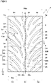
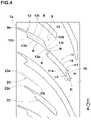
FIG. 4 is an enlarged view of some first lateral grooves ofFIG. 1 ; and -
FIG. 5 is a development view of the tread portion according to another embodiment. - Hereinafter, an embodiment of the present disclosure will be described with reference to the drawings.
FIG. 1 is a development view of atread portion 2 of a motorcycle tyre (hereafter, it may be simply referred to as "tyre".) 1 of an embodiment according to the present disclosure. Thetyre 1 according to the present embodiment may suitably be used for on-road driving such as on a dry asphalt road surface. Alternatively, thetyre 1 according to the present disclosure is not limited to such an aspect. - The
tread portion 2, in the present embodiment, includes a crown portion Cr that is a region of 50% of a tread development width TWe centered on the tyre equator C, and a firstshoulder portion S 1 that is an outer region of the crown portion Cr (left side of the crown portion Cr inFIG. 1 ). In addition, thetread portion 2 includes a second shoulder portion S2 that is located on the opposite side with respect to the first shoulder portion S 1 (right side of the crown portion Cr inFIG. 1 ). The crown portion Cr is a region that comes into contact with the ground when traveling straight mainly. The firstshoulder portion S 1 and the second shoulder portion S2 are regions that come into contact with the ground when turning. As used herein, the tread development width TWs is a distance in the tyre axial direction between tread edges Te when thetread portion 2 is developed on a plane. - In the present embodiment, the
tread portion 2 is provided with a plurality of firstlateral grooves 8. Each firstlateral groove 8 includes afirst groove portion 11 arranged in the crown portion Cr, asecond groove portion 12 arranged in the first shoulder portion S1, and athird groove portion 13 connecting thefirst groove portion 11 and thesecond groove portion 12. Since each firstlateral groove 8 extends from the crown portion Cr to the first shoulder portion S1, each firstlateral groove 8 can come into contact with the ground in a wide range from straight running to turning so as to improve drainage. In addition, since each firstlateral groove 8 may be greater in axial length than a ground contact width when running, the air between the road surface and the groove may be discharged from the non-grounded area, improving noise resistance. -
FIG. 2A is an enlarged view of one of the firstlateral grooves 8.FIG. 2B is a cross-sectional view taken along the line A-A ofFIG. 1 . As illustrated inFIGS. 2A and 2B , a groove depth D3 and a groove width W3 of thethird groove portion 13 are respectively smaller than a groove depth D1 and a groove width W1 of thefirst groove portion 11. Further, the groove depth D3 and the groove width W3 of thethird groove portion 13 are respectively smaller than a groove depth D2 and a groove width W2 of thesecond groove portion 12. Such athird groove portion 13 can suppress deformation of thefirst groove portion 11 and thesecond groove portion 12 during running to improve uneven wear resistance and vibration resistance. In addition, forwide tyres 1 where a rubber thickness of thetread portion 2 tends to be small, the transient characteristics that is stability of handling during turning can be improved by providing thethird groove portion 13. As used herein, unless otherwise noted, the dimensions of portions of the tyre are the values measured with thetyre 1 under a normal state. - As used herein, the "normal state" is such that the
tyre 1 is mounted onto a standard wheel rim (not illustrated) with a standard internal pressure but loaded with no tyre load. - As used herein, the "standard wheel rim" is a wheel rim officially approved for each tyre by standards organizations on which the
tyre 1 is based, wherein the standard wheel rim is the "standard rim" specified in JATMA, the "Design Rim" in TRA, and the "Measuring Rim" in ETRTO, for example. - As used herein, the "standard internal pressure" is a standard internal pressure officially approved for each tyre by standards organizations on which the
tyre 1 is based, wherein the standard internal pressure is the "maximum air pressure" in JATMA, the maximum pressure given in the "Tire Load Limits at Various Cold Inflation Pressures" table in TRA, and the "Inflation Pressure" in ETRTO, for example. - More than 80% of a tyre axial length L3 of the
third groove portion 13 is located in the firstshoulder portion S 1. Thus, the rigidity of the firstshoulder portion S 1, which may receive a large camber thrust when cornering, can be maintained high, and vibration during running and uneven wear can be suppressed. Further, since the concentration of deflection in thetyre 1 may be alleviated, the occurrence of cracks at the bottom of the groove can be suppressed. In the present embodiment, a 100% of the tyre axial length L3 of thethird groove portion 13 is located in the first shoulder portion S1. - The
tread portion 2 according to the present embodiment is preferably used for a front wheel tyre of motorcycles. Alternatively, thetread portion 2 according to the present embodiment may be used for a rear wheel tyre. -
FIG. 3 illustrates a cross-sectional view taken along the line B-B ofFIG. 1 . As illustrated inFIG. 3 , in order to ensure a sufficient ground contact area when turning with large camber angles, thetread portion 2 of thetyre 1 has aground contact surface 2a that is curved in an arc shape manner so as to be convex outward in the tyre radial direction. - The
tyre 1, for example, includes acarcass 6 extending between a pair ofbead portions band layer 7 disposed outward in the tyre radial direction of thecarcass 6 in thetread portion 2. - The
carcass 6, for example, includes two carcass plies 6A and 6B which are superimposed in the tyre radial direction. The carcass plies 6A and 6B, for example, include carcass cords (not illustrated) oriented at an angle of from 30 to 45 degrees with respect to the tyre circumferential direction, and thus thecarcass 6 is configured as a bias structure. For the carcass plies 6A and 6B, well-known cord materials can be used. Tires with a bias structure have a characteristic that the rigidity of thetread portions 2 may be smaller and these are easier to deformed thantyres 1 with a radial structure. In the present disclosure, it is possible to improve vibration resistance and uneven wear resistance not only in tyres having a radial structure but also in tyres having a bias structure by the above configuration. - The
band layer 7, in the present embodiment, includes a single band ply having a band cord (not illustrated) which is wound spirally at an angle of 5 degrees or less with respect to the tyre circumferential direction. For the band ply, a well-known material can be used. - As illustrated in
FIG. 1 , thetread portion 2 according to the present embodiment has a designated rotation direction N. In each firstlateral groove 8, thefirst groove portion 11 is located on a leading side than thesecond groove portion 12 with respect to the rotation direction N. Thus, in each firstlateral groove 8, the water under thetyre 1 can smoothly be discharged from the tyre equator C side to the tread edge Te side by the rotation of thetyre 1, and the drainage can be improved. - The first
lateral grooves 8, for example, are provided on both sides of the tyre equator C. In the present embodiment, the left side firstlateral grooves 8 and the right side firstlateral grooves 8 are arranged alternately in the tyre circumferential direction. The firstlateral grooves 8, in the present embodiment, do not cross the tyre equator C. In other words, thefirst groove portions 11 are located so as not to cross the tyre equator C. Such a layout can maintain the rigidity of thetread portion 2 around the tyre equator C, which is subject to large ground pressure, and can maintain uneven wear resistance and vibration resistance. In the present specification, for grooves and sipes of the same shape arranged on both sides of the tyre equator C, the grooves and sipes on the first shoulder portion S1 are described, and the explanation of the grooves and sipes on the second shoulder portion S2 is omitted. - As illustrated in
FIG. 2A , in each firstlateral groove 8, thefirst groove portion 11, thesecond groove portion 12 and thethird groove portion 13, for example, are inclined in the same direction with respect to the tyre axial direction. This makes the flow of water in each firstlateral groove 8 smoother. Angles θ1, θ2 and θ3 with respect to the tyre axial direction of thefirst groove portion 11, thesecond groove portion 12 and thethird groove portion 13, respectively, are preferably in a range from 20 to 60 degrees. The absolute value of the difference among the angle θ1 of thefirst groove portion 11, the angle θ2 of thesecond groove portion 12 and the angle θ3 of the third groove portion 13 (|θ1 - θ2|, | θ2 - θ3|, and |θ3 - θ1|) are preferably in a range of from 30 to 50 degrees. As used herein, each of the angles θ1, θ2 and θ3 is an average value of the maximum value and the minimum value of each of the first, second andthird groove portions - In each first
lateral groove 8, thefirst groove portion 11, for example, includes afirst groove edge 11e located on a first side (below inFIG. 2 ) in the tyre circumferential direction and asecond groove edge 11i located on a second side (above inFIG. 2 ) in the tyre circumferential direction. Thesecond groove edge 11i of thefirst groove portion 11, for example, includes a bent point F, and an angle of thesecond groove edge 11i with respect to the tyre axial direction changes locally via the bent point F. Thesecond groove edge 11i includes anouter portion 15 located outward in the tyre axial direction of the bent point F, and aninner portion 16 located inward in the tyre axial direction of the bent point F. Thefirst groove edge 11e of thefirst groove portion 11 extends smoothly without having a bent portion. Thefirst groove edge 11e and thesecond groove edge 11i, for example, are connected to aninner end 8i of the firstlateral groove 8. Theinner end 8i, in the present specification, is the innermost end in the tyre axial direction of thegroove centerline 8c of the firstlateral groove 8. In addition, theinner end 8i includes an arc portion having a radius of curvature r of equal to or less than 2 mm in this specification. - The
first groove edge 11e and theouter portion 15, for example, include arc portions R extending in an arc shape manner so as to be convex in one direction in the tyre circumferential direction. The arc portions R of thefirst groove edge 11e and theouter portion 15, in the present embodiment, protrude toward the rearward with respect to the rotation direction N. Theinner portion 16 according to the present embodiment extends straight. -
FIG. 4 illustrates an enlarged view of one of the firstlateral grooves 8. As illustrated inFIG. 4 , in each firstlateral groove 8, an angle α1 with respect to the tyre axial direction of theinner portion 16 is greater than an angle α2 with respect to the tyre axial direction of thefirst groove edge 11e. Thus, thefirst groove portion 11 formed by theinner portion 16 has a groove width w tapering toward theinner end 8i. Such afirst groove portion 11 can smoothly guide water and air into thefirst groove portion 11 utilizing the rotation of thetyre 1 while suppressing the decrease in rigidity of the crown portion Cr. - The
second groove portion 12, for example, includes afirst groove edge 12e located on the first side in the tyre circumferential direction and asecond groove edge 12i located on the second side in the tyre circumferential direction. Thefirst groove edge 12e and thesecond groove edge 12i, for example, include arc portions R extending in an arc shape manner so as to be convex in one direction (the first side) in the tyre circumferential direction. The arc portions R of thefirst groove edge 12e and thesecond groove edge 12i, in the present embodiment, protrude toward rearward with respect to the rotation direction N. - The
third groove portion 13 is arranged nearer to thesecond groove edge 11i of thefirst groove portion 11 than thefirst groove edge 11e of thefirst groove portion 11, and is arranged nearer to thefirst groove edge 12e of thesecond groove portion 12 than thesecond groove edge 12i of thesecond groove portion 12. In other words, in each firstlateral groove 8 according to the present embodiment, avirtual line 12k in which thegroove centerline 12c of thesecond groove portion 12 is expanded inward smoothly in the tyre axial direction is located on the rearward than thethird groove portion 13 in the rotation direction N. This feature may help to suppress cracks on the groove bottom of the firstlateral groove 8. - The
third groove portion 13, for example, includes afirst groove edge 13e located on the first side in the tyre circumferential direction and asecond groove edge 13i located on the second side in the tyre circumferential direction. Thefirst groove edge 13e of thethird groove portion 13, for example, includes a crank-shaped portion K that extends in a crank shape manner toward thefirst groove edge 11e of thefirst groove portion 11. Thesecond groove edge 13i of thethird groove portion 13, for example, includes an arc portion R that is convex on the opposite side to the convex of thesecond groove edge 11i of thefirst groove portion 11. - In the present embodiment, the groove width w of the
third groove portion 13 suddenly decreases between thefirst groove portion 11 and thesecond groove portion 12. Preferably, a ratio of the change of the groove width w to a unit length of the groove is equal to or more than 0.4. - As illustrated in
FIG. 2A , in each firstlateral groove 8, the groove width W3 of thethird groove portion 13 is preferably equal to or more than 15% of the groove widths W1 and W2 of thefirst groove portion 11 and thesecond groove portion 12, respectively, more preferably equal to or more than 20%, but preferably equal to or less than 50% of the groove widths W1 and W2, more preferably equal to or less than 45%. When the groove width W3 of thethird groove portion 13 is equal to or more than 15% of the groove widths W1 and distorted W2 of thefirst groove portion 11 and thesecond groove portion 12, respectively, drainage can be ensured. When the groove width W3 of thethird groove portion 13 is equal to or less than 50% of the groove widths W1 and distorted W2 of thefirst groove portion 11 and thesecond groove portion 12, respectively, uneven wear resistance and vibration resistance can be improved. Note that in each firstlateral groove 8, the groove width W3 of thethird groove portion 13 means the minimum groove width of thethird groove portion 13. Further, note that in each firstlateral groove 8, the groove widths W1 and W2 of thefirst groove portion 11 and thesecond groove portion 12 are the maximum groove width of thefirst groove portion 11 and the maximum groove width of thesecond groove portion 12, respectively. Although not particularly limited, the groove width W1 of eachfirst groove portion 11 is in a range from 3.5 to 7.0 mm. - As illustrated in
FIG. 2B , from a similar point of view, in each firstlateral groove 8, the groove depth D3 of thethird groove portion 13 is preferably equal to or more than 15% of the groove depths D1 and D2 of thefirst groove portion 11 and thesecond groove portion 12, respectively, more preferably equal to or more than 20%, but preferably equal to or less than 50% of the groove depths D1 and D2 of thefirst groove portion 11 and thesecond groove portion 12, respectively, more preferably equal to or less than 45%. Note that in each firstlateral groove 8, the groove depth D3 of thethird groove portion 13 means the minimum groove depth of thethird groove portion 13. Further, note that in each firstlateral groove 8, the groove depths D1 and D2 of thefirst groove portion 11 and thesecond groove portion 12, respectively, are the maximum groove depths of thefirst groove portion 11 and the maximum groove depth of thesecond groove portion 12, respectively. Although not particularly limited, the groove depth D1 of eachfirst groove portion 11 is in a range from 3.0 to 7.5 mm. - As illustrated in
FIG. 2A , the length L3 in the tyre axial direction of thethird groove portion 13 is preferably equal to or more than 10% of a development length Ws (shown inFIG. 1 ) in the tyre axial direction of the firstshoulder portion S 1, more preferably, equal to or more than 15%, but preferably equal to or less than 30% of the development length Ws, more preferably equal to or less than 25%. - Each first
lateral groove 8, for example, further includes afourth groove portion 14 extending outward in the tyre axial direction from thesecond groove portion 12. A groove width W4 of thefourth groove portion 14 is smaller than the groove widths W1 and W2 of thefirst groove portion 11 and thesecond groove portion 12, respectively. Further, a groove depth D4 of thefourth groove portion 14 is smaller than the groove depths D1 and D2 of thefirst groove portion 11 and thesecond groove portion 12, respectively. Such afourth groove portion 14 can also enhance drainage and suppress uneven wear resistance and deterioration of vibration resistance. Thefourth groove portion 14 can come into contact with the ground during turning with large camber angles. Hence, by setting the groove depth D4 and the groove width W4 of thefourth groove portion 14 small as described above, the reduction in rigidity of theground contact surface 2a can be prevented. Thus, a rider of a motorcycle during turning with large camber angles can return the motorcycle smoothly to straight running condition. Therefore, handling of motorcycle can be lighter. In the present embodiment, thefourth groove portion 14 is greater in axial length than thethird groove portion 13, and the fourth groove portion is smaller in angle with respect to the tyre axial direction than the third groove portion. - In the present embodiment, the groove depth D4 and the groove width W4 of the
fourth groove portion 14, for example, are substantially the same as the groove depth D3 and the groove width W3 of thethird groove portion 13, respectively. Such afourth groove portion 14 can effectively exert the above-mentioned effects. The above-mentioned "substantially the same" means that the difference between the groove depth D4 of thefourth groove portion 14 and the groove depth D3 of thethird groove portion 13 is within 2 mm. It also means that the difference between the groove width W4 of thefourth groove portion 14 and the groove width W3 of thethird groove portion 13 is within 2 mm. - Each
fourth groove portion 14, in the present embodiment, is inclined in the same direction as the inclination direction of thesecond groove portion 12 with respect to the tyre circumferential direction. Such afourth groove portion 14 can maintain smooth water flow in the firstlateral groove 8. - An
outer end 14a in the tyre axial direction of eachfourth groove portion 14 is located within the first shoulder portion S1. In other words, eachfourth groove portion 14 terminates within the first shoulder portion S1 so as not to traverse the tread edge Te. Such afourth groove portion 14 can suppress the decrease in rigidity of thetread portion 2 on the tread edge Te on which a large lateral force acts. - In each first
lateral groove 8, thefourth groove portion 14 is arranged nearer to thesecond groove edge 12i of thesecond groove portion 12 than thefirst groove edge 12e of thesecond groove portion 12. Eachfourth groove portion 14 includes afirst groove edge 14e on the first side in the tyre circumferential direction and asecond groove edge 14i located on the second side in the tyre circumferential direction. Thesecond groove edge 14i of thefourth groove portion 14 is connected to thesecond groove edge 12i of thesecond groove portion 12 so as to form a single circular arc. Thefirst groove edge 14e of thefourth groove portion 14 includes a crank-shaped portion K extending in a crank shape manner and connected to thesecond groove edge 12e of thesecond groove portion 12. - As illustrated in
FIG. 2B , a groove bottom 11s of thefirst groove portion 11 and a groove bottom 13s of thethird groove portion 13 are smoothly connected. Agroove bottom 12s of thesecond groove portion 12 and a groove bottom 13s of thethird groove portion 13 are smoothly connected. Further, the groove bottom 12s of thesecond groove portion 12 and a groove bottom 14s of thefourth groove portion 14 are smoothly connected. Such a firstlateral groove 8 can suppress the occurrence of cracks at the groove bottoms and smooth the flow of water in the groove. The above-mentioned "smoothly connected" means that each connected portion among thegroove bottoms inner arc portion 17a which is convex inward in the tyre radial direction, and anouter arc portion 17b which is convex outward in the tyre radial direction and is located outward in the tyre radial direction than theinner arc portion 17a. - As illustrated in
FIG. 1 , thetread portion 2, for example, is provided with acircumferential groove 20, a plurality of secondlateral grooves 21, a plurality of thirdlateral grooves 22, and a plurality ofsipes 23. As used herein, the grooves such as the firstlateral grooves 8 and thecircumferential groove 20 are voids that have a maximum groove width greater than 1.5 mm. As used herein, "sipe" means an incision that has a maximum width equal to or less than 1.5 mm. - The
circumferential groove 20, for example, extends continuously in the tyre circumferential direction on the tyre equator C. Thecircumferential groove 20 according to the present embodiment extends in a zigzag manner which includesfirst portions 20A inclined in a first direction (downward left inFIG. 1 ) with respect to the tyre circumferential direction andsecond portions 20B inclined in the opposite direction to thefirst portions 20A with respect to the tyre circumferential direction. - The
circumferential groove 20 includes a pair ofgroove edges circumferential groove 20 extends on the tyre equator C in a zigzag manner, each of the pair ofgroove edges 20e includesouter portions 25 located outward in the tyre axial direction than the other groove edge, andinner portions 26 located inward in the tyre axial direction than the other groove edge, wherein theouter portions 25 and theinner portions 26 are arranged alternately in the tyre circumferential direction. In connecting portions between thefirst portions 20A and thesecond portions 20B, theouter portions 25 are configured to include axial portions J that extend in the tyre axial direction. Such an axial portion J can collect water under theground contact surface 2a into thecircumferential groove 20 to improve drainage. - In the present embodiment, the second
lateral grooves 21, the thirdlateral grooves 22 and thesipes 23 are arranged on both sides of the tyre equator C. The secondlateral grooves 21, the thirdlateral grooves 22 and thesipes 23, for example, are inclined rearward in the rotation direction N toward the respective tread edges Te. In the present embodiment, the secondlateral grooves 21, the thirdlateral grooves 22 and thesipes 23 are curved in an arc manner so as to be convex rearward in the rotation direction N. The secondlateral grooves 21, the thirdlateral grooves 22 and thesipes 23, for example, terminate without reaching the tread edges Te. - On the left side of the tyre equator C, the second
lateral grooves 21, for example, extend from the crown portion Cr to the first shoulder portion S1. In the present embodiment, the secondlateral grooves 21 have a length in the tyre axial direction greater than that of the firstlateral grooves 8. Inner ends 21i in the tyre axial direction of the secondlateral grooves 21, for example, are located nearer to the tyre equator C than the inner ends 8i of the firstlateral grooves 8. - On the left side of the tyre equator C, the third
lateral grooves 22, for example, extend from the crown portion Cr to the first shoulder portion S1. The thirdlateral grooves 22 have a length in the tyre axial direction smaller than that of the firstlateral grooves 8. Axial inner ends 22i of the thirdlateral grooves 22 are located nearer to the tread edge Te than the inner ends 8i of the firstlateral grooves 8. Axial outer ends 22e of the thirdlateral grooves 22 are located nearer to the tyre equator C than the outer ends 8e (shown inFIG. 4 ) of the firstlateral grooves 8. - On the left side of the tyre equator C, as illustrated in
FIG. 4 , thesipes 23 are arranged in the first shoulder portion S1. Inner ends 23i in the tyre axial direction of thesipes 23 are located within the first shoulder portion S1. Outer ends 23e in the tyre axial direction of thesipes 23 are, in the tyre axial direction, arranged between the outer ends 8e of the firstlateral grooves 8 and the outer ends 22e of the thirdlateral grooves 22. -
FIG.5 illustrates a development view of thetread portion 2 in accordance with another embodiment. The same elements which have already explained in the above embodiment are designated by the same reference numerals and the description thereof may be omitted. In this embodiment, thetread portion 2 is preferably used for rear wheel tyres of motorcycles. Alternatively, thetread portion 2 may be used for front wheel tyres. - As illustrated in
FIG. 5 , thetread portion 2 according to the present embodiment includes the firstlateral grooves 8, the secondlateral grooves 21, the thirdlateral grooves 22 and thesipes 23. Thetread portion 2 according to this embodiment is not provided with any circumferential grooves. As to thesipes 23, for example, a set of two sipes are provided in each region between one of the firstlateral grooves 8 and one of the secondlateral grooves 21 which are directly adjacent in the tyre circumferential direction. - In this embodiment, the inner ends 21i of the second
lateral grooves 21 are located inward in the tyre axial direction than the inner ends 21i of the secondlateral grooves 21 of the previous embodiment. This can suppress the deterioration of drainage. The shortest distance Lb between the inner ends 21i of the secondlateral grooves 21 and the tyre equator C is preferably equal to or more than 0.5%, more preferably equal to or more than 0.7%, of a development width Wc of the crown portion Cr, but preferably equal to or less than 2.0%, more preferably equal to or less than 2.5% of the width Ws. - Motorcycles include front wheel tyres and rear wheel tyres (not illustrated). Rear wheel tyres are not significantly affected by the rider's steering wheel operation. For such tyres, grip performance is more important than handling performance. Thus, it is preferable that a land ratio of the
tread portion 2 of the rear wheel tyres is larger than a land ratio of thetread portion 2 of the front wheel tyre. In particular, a land ratio of thetread portion 2 of rear wheel tyres is preferably equal to or more than 80%. - Although some particularly preferable embodiments of the present disclosure have been described in detail above, the present disclosure is not limited to the embodiments shown in drawings.
- Motorcycle tyres with the basic tread pattern of
FIG. 1 was prepared. Then, handling performance, drainage performance, uneven wear resistance, durability, vibration resistance, and noise resistance of each test tyre were tested. The common specifications and test methods for each sample tyre are as follows. - Handling performance, uneven wear resistance, durability, vibration resistance, noise resistance test:
Each test tyre was mounted on the front wheel of a motorcycle (displacement 1500cc) under the following conditions. The same tyre with a tread pattern was used for the rear wheel tyre. Then, a test rider drove the motorcycle on a dry asphalt road surface, and lightness of handling, degree of vibration and noise at that time were evaluated by the sensuality of the test rider. In addition, occurrence of uneven wear after running and the occurrence of cracks on the bottoms of grooves were checked. The test results are shown in Table 1 using scoring with Ref. 1 as 100. Each performance is better when the numerical value is larger, wherein 95 or more is passed. - Front tyre specifications (size, rim, internal pressure):
110 / 70-13M/C, 13x3.00MT, 200 kPa - Rear wheel tyre specifications (size, rim, internal pressure):
130 / 70-13M/C, 13x3.50MT, 225 kPa - Drainage test:
Using the above motorcycle, the test rider drove the motorcycle on a wet asphalt road surface, and the ease of running at that time was evaluated by the sensuality of the test rider. The test results are shown in Table 1 using a score with Ref. 1 as 100. The larger the value, the better the drainage property, wherein 95 or more is passed. - Table 1 shows the test results.
- In Table 1, "A" represents that the positions of the second groove portions are at the positions shown in
FIG. 1 . - "B" represents that the second groove portions are located in the crown portion.
- "C" represents that the positions of the third groove portions are at the positions shown in
FIG.1 . - "D" represents that the third groove portions are located in the crown portion.
- "E" represents that 80% of the length of each third groove portion is located in the first shoulder portion.
- "F" represents that 70% of the length of each third groove portion is located in the first shoulder portion.
- "G" represents that the bottoms of the groove portions of each first lateral groove is configured as the embodiment shown in
FIG. 2B . - "H" represents that the bottoms of the groove portions of each first lateral groove are connected in a straight-line shape.
- "I" represents that the inner portion of each first groove portion is in the aspect of
FIG.1 . - "J" represents that the inner portion of each first groove portion extends with a constant width.
- The lengths of the third groove portions are all the same.
[Table 1] Ref. 1 Ref. 2 Ref. 3 Ex. 1 Ex. 2 Ex. 3 Ex. 4 Ex. 6 Ex. 6 Ex. 7 Ref. 4 Locations of second groove portions of first lateral grooves B A A A A A A A A A A Locations of third groove portions C C D C C C C C C E F L3 (%) 0 100 100 100 100 100 100 100 100 100 100 D3/D1 (%) 25 100 25 25 25 50 25 25 25 25 25 W3/W1 (%) 25 25 25 25 25 50 25 25 25 25 25 Fourth groove portions applied applied applied applied none applied applied applied applied applied applied D4/D1 (%) 25 25 25 25 - 25 50 25 25 25 25 Shapes of groove bottoms of first lateral grooves G G G G G G G H G G G Shapes of inner portions of first groove portions I I I I I I I I J I I Handling performance [score: Larger is better.] 100 100 95 100 95 95 100 100 100 100 100 Uneven wear resistance [score: Larger is better.] 100 95 90 105 105 100 100 95 95 100 90 Durability [score: Larger is better.] 100 95 100 100 105 100 100 95 95 100 100 Vibration resistance [score: Larger is better.] 100 90 95 105 105 105 100 100 100 105 95 Noise resistance [score: Larger is better.] 100 105 105 100 100 100 100 105 105 100 100 Drainage performance [score: Larger is better.] 100 115 110 110 105 115 115 115 115 110 105 - As a result of the tests, it is understood that the tyres of example have improved drainage performance without impairing the uneven wear resistance and vibration resistance as compared with the tyres of comparative example.
- The following additional notes are disclosed regarding the above-described embodiments.
- A motorcycle tyre comprising:
- a tread portion comprising a crown portion that is a region of 50% of a tread development width centered on a tyre equator, a first shoulder portion that is an outer region of the crown portion, and a plurality of first lateral grooves,
- each of the plurality of first lateral grooves comprising a first groove portion arranged in the crown portion, a second groove portion arranged in the first shoulder portion, and a third groove portion connecting the first groove portion and the second groove portion,
wherein - a groove depth and a groove width of the third groove portion are respectively smaller than a groove depth and a groove width of the first groove portion,
- the groove depth and the groove width of the third groove portion are respectively smaller than a groove depth and a groove width of the second groove portion, and
- more than 80% of a tyre axial length of the third groove portion is located in the first shoulder portion.
-
- The motorcycle tyre according to
Additional note 1, wherein - in each of the plurality of first lateral grooves, the first groove portion does not cross the tyre equator.
- The motorcycle tyre according to
Additional note
in each of the plurality of first lateral grooves, the first groove portion, the second groove portion and the third groove portion are inclined in a same direction with respect to the tyre axial direction. - The motorcycle tyre according to any one of
Additional notes 1 to 3, wherein
in each of the plurality of first lateral grooves, the groove width of the third groove portion is in a range from 15% to 50% of the groove width of the first groove portion and the groove width of the second groove portion. - The motorcycle tyre according to anyone of
Additional notes 1 to 4, wherein
in each of the plurality of first lateral grooves, the groove depth of the third groove portion is in a range from 15% to 50% of the groove depth of the first groove portion and the groove depth of the second groove portion. - The motorcycle tyre according to any one of
Additional notes 1 to 5, wherein - in each of the plurality of first lateral grooves,
- the first groove portion comprises a first groove edge located on a first side in a tyre circumferential direction and a second groove edge located on a second side in the tyre circumferential direction,
- the second groove portion comprises a first groove edge located on the first side in the tyre circumferential direction and a second groove edge located on the second side in the tyre circumferential direction, and
- the third groove portion is arranged nearer to the second groove edge of the first groove portion than the first groove edge of the first groove portion, and is arranged nearer to the first groove edge of the second groove portion than the second groove edge of the second groove portion.
- The motorcycle tyre according to any one of
Additional notes 1 to 6, wherein - each of the plurality of first lateral grooves further comprises a fourth groove portion extending outward in the tyre axial direction from the second groove portion, and
- a groove depth and a groove width of the fourth groove portion is respectively smaller than the groove depths and the groove widths of the first groove portion and the second groove portion, respectively.
- The motorcycle tyre according to
Additional note 7, wherein - in each of the plurality of first lateral grooves,
- the first groove portion, the second groove portion, the third groove portion, and the fourth groove portion are inclined in a same direction with respect to the tyre axial direction.
- The motorcycle tyre according to any one of
Additional notes 1 to 8, wherein - the tread portion has a designated rotation direction, and
- the first groove portion is located on a leading side than the second groove portion with respect to the rotation direction.
- The motorcycle tyre according to any one of
Additional notes 1 to 9, further comprising a carcass having a bias structure. - A set of motorcycle tyres comprising:
- a motorcycle tyre for front wheel according to any one of
Additional notes 1 to 10, and - a motorcycle tyre for rear wheel according to any one of
Additional notes 1 to 10, - wherein
- a land ratio of the motorcycle tyre for rear wheel is greater than a land ratio of the motorcycle tyre for front wheel.
Claims (11)
- A motorcycle tyre comprising:a tread portion comprising a crown portion that is a region of 50% of a tread development width centered on a tyre equator, a first shoulder portion that is an outer region of the crown portion, and a plurality of first lateral grooves,each of the plurality of first lateral grooves comprising a first groove portion arranged in the crown portion, a second groove portion arranged in the first shoulder portion, and a third groove portion connecting the first groove portion and the second groove portion,
whereina groove depth and a groove width of the third groove portion are respectively smaller than a groove depth and a groove width of the first groove portion,the groove depth and the groove width of the third groove portion are respectively smaller than a groove depth and a groove width of the second groove portion, andmore than 80% of a tyre axial length of the third groove portion is located in the first shoulder portion. - The motorcycle tyre according to claim 1, wherein
in each of the plurality of first lateral grooves, the first groove portion does not cross the tyre equator. - The motorcycle tyre according to claim 1 or 2, wherein
in each of the plurality of first lateral grooves, the first groove portion, the second groove portion and the third groove portion are inclined in a same direction with respect to the tyre axial direction. - The motorcycle tyre according to any one of claims 1 to 3, wherein
in each of the plurality of first lateral grooves, the groove width of the third groove portion is in a range from 15% to 50% of the groove width of the first groove portion and the groove width of the second groove portion. - The motorcycle tyre according to any one of claims 1 to 4, wherein
in each of the plurality of first lateral grooves, the groove depth of the third groove portion is in a range from 15% to 50% of the groove depth of the first groove portion and the groove depth of the second groove portion. - The motorcycle tyre according to any one of claims 1 to 5, whereinin each of the plurality of first lateral grooves,the first groove portion comprises a first groove edge located on a first side in a tyre circumferential direction and a second groove edge located on a second side in the tyre circumferential direction,the second groove portion comprises a first groove edge located on the first side in the tyre circumferential direction and a second groove edge located on the second side in the tyre circumferential direction, andthe third groove portion is arranged nearer to the second groove edge of the first groove portion than the first groove edge of the first groove portion, and is arranged nearer to the first groove edge of the second groove portion than the second groove edge of the second groove portion.
- The motorcycle tyre according to any one of claims 1 to 6, whereineach of the plurality of first lateral grooves further comprises a fourth groove portion extending outward in the tyre axial direction from the second groove portion, anda groove depth and a groove width of the fourth groove portion is respectively smaller than the groove depths and the groove widths of the first groove portion and the second groove portion, respectively.
- The motorcycle tyre according to claim 7, whereinin each of the plurality of first lateral grooves,the first groove portion, the second groove portion, the third groove portion, and the fourth groove portion are inclined in a same direction with respect to the tyre axial direction.
- The motorcycle tyre according to any one of claims 1 to 8, whereinthe tread portion has a designated rotation direction, andthe first groove portion is located on a leading side than the second groove portion with respect to the rotation direction.
- The motorcycle tyre according to any one of claims 1 to 9, further comprising a carcass having a bias structure.
- A set of motorcycle tyres comprising:a motorcycle tyre for front wheel according to any one of claims 1 to 10, anda motorcycle tyre for rear wheel according to any one of claims 1 to 10,whereina land ratio of the motorcycle tyre for rear wheel is greater than a land ratio of the motorcycle tyre for front wheel.
Applications Claiming Priority (1)
| Application Number | Priority Date | Filing Date | Title |
|---|---|---|---|
| JP2021066060A JP2022161333A (en) | 2021-04-08 | 2021-04-08 | Tire for motor cycle |
Publications (2)
| Publication Number | Publication Date |
|---|---|
| EP4070969A1 true EP4070969A1 (en) | 2022-10-12 |
| EP4070969B1 EP4070969B1 (en) | 2024-05-01 |
Family
ID=80628572
Family Applications (1)
| Application Number | Title | Priority Date | Filing Date |
|---|---|---|---|
| EP22160039.8A Active EP4070969B1 (en) | 2021-04-08 | 2022-03-03 | Motorcycle tyre |
Country Status (4)
| Country | Link |
|---|---|
| US (1) | US20220332146A1 (en) |
| EP (1) | EP4070969B1 (en) |
| JP (1) | JP2022161333A (en) |
| CN (1) | CN115195353A (en) |
Citations (5)
| Publication number | Priority date | Publication date | Assignee | Title |
|---|---|---|---|---|
| US20160221398A1 (en) * | 2015-01-30 | 2016-08-04 | Sumitomo Rubber Industries, Ltd. | Pneumatic motorcycle tire |
| JP2019104329A (en) | 2017-12-11 | 2019-06-27 | 住友ゴム工業株式会社 | Motorcycle tire |
| US20200282775A1 (en) * | 2019-03-05 | 2020-09-10 | Sumitomo Rubber Industries, Ltd. | Tyre |
| US20200282774A1 (en) * | 2019-03-05 | 2020-09-10 | Sumitomo Rubber Industries, Ltd. | Tyre |
| WO2021060033A1 (en) * | 2019-09-24 | 2021-04-01 | 株式会社ブリヂストン | Motorbike tire |
-
2021
- 2021-04-08 JP JP2021066060A patent/JP2022161333A/en active Pending
-
2022
- 2022-03-03 EP EP22160039.8A patent/EP4070969B1/en active Active
- 2022-03-10 US US17/691,254 patent/US20220332146A1/en active Pending
- 2022-03-11 CN CN202210241803.0A patent/CN115195353A/en active Pending
Patent Citations (5)
| Publication number | Priority date | Publication date | Assignee | Title |
|---|---|---|---|---|
| US20160221398A1 (en) * | 2015-01-30 | 2016-08-04 | Sumitomo Rubber Industries, Ltd. | Pneumatic motorcycle tire |
| JP2019104329A (en) | 2017-12-11 | 2019-06-27 | 住友ゴム工業株式会社 | Motorcycle tire |
| US20200282775A1 (en) * | 2019-03-05 | 2020-09-10 | Sumitomo Rubber Industries, Ltd. | Tyre |
| US20200282774A1 (en) * | 2019-03-05 | 2020-09-10 | Sumitomo Rubber Industries, Ltd. | Tyre |
| WO2021060033A1 (en) * | 2019-09-24 | 2021-04-01 | 株式会社ブリヂストン | Motorbike tire |
Also Published As
| Publication number | Publication date |
|---|---|
| CN115195353A (en) | 2022-10-18 |
| US20220332146A1 (en) | 2022-10-20 |
| EP4070969B1 (en) | 2024-05-01 |
| JP2022161333A (en) | 2022-10-21 |
Similar Documents
| Publication | Publication Date | Title |
|---|---|---|
| EP2135752B1 (en) | Motorcycle tire | |
| US9789736B2 (en) | Pneumatic tire | |
| US10500901B2 (en) | Motorcycle pneumatic tire | |
| US10889149B2 (en) | Pneumatic tire | |
| US20130292021A1 (en) | Pneumatic tire | |
| EP3056358B1 (en) | Motorcycle tire | |
| JP5109823B2 (en) | Pneumatic tire | |
| US11214096B2 (en) | Pneumatic tyre | |
| EP3424752B1 (en) | Pneumatic tire | |
| US11077714B2 (en) | Tire and three-wheeled vehicle with the same | |
| EP4070969B1 (en) | Motorcycle tyre | |
| EP4043241B1 (en) | Motorcycle tyre | |
| US11904639B2 (en) | Tire | |
| EP4144540B1 (en) | Tyre | |
| US11820175B2 (en) | Tyre | |
| EP4032726A1 (en) | Motorcycle tire and front and rear motorcycle tires | |
| US11865867B2 (en) | Motorcycle tire | |
| US11077713B2 (en) | Tire | |
| EP4032725A1 (en) | Motorcycle tyre | |
| EP4219193A1 (en) | Tyre and method for using the same | |
| EP3546250B1 (en) | Tire | |
| US10940720B2 (en) | Tire for motorcycles | |
| CN117885472A (en) | Tire with a tire body | |
| CN114829163A (en) | Tyre for vehicle wheels |
Legal Events
| Date | Code | Title | Description |
|---|---|---|---|
| PUAI | Public reference made under article 153(3) epc to a published international application that has entered the european phase |
Free format text: ORIGINAL CODE: 0009012 |
|
| STAA | Information on the status of an ep patent application or granted ep patent |
Free format text: STATUS: THE APPLICATION HAS BEEN PUBLISHED |
|
| AK | Designated contracting states |
Kind code of ref document: A1 Designated state(s): AL AT BE BG CH CY CZ DE DK EE ES FI FR GB GR HR HU IE IS IT LI LT LU LV MC MK MT NL NO PL PT RO RS SE SI SK SM TR |
|
| STAA | Information on the status of an ep patent application or granted ep patent |
Free format text: STATUS: REQUEST FOR EXAMINATION WAS MADE |
|
| 17P | Request for examination filed |
Effective date: 20221111 |
|
| RBV | Designated contracting states (corrected) |
Designated state(s): AL AT BE BG CH CY CZ DE DK EE ES FI FR GB GR HR HU IE IS IT LI LT LU LV MC MK MT NL NO PL PT RO RS SE SI SK SM TR |
|
| P01 | Opt-out of the competence of the unified patent court (upc) registered |
Effective date: 20230510 |
|
| RIC1 | Information provided on ipc code assigned before grant |
Ipc: B60C 11/117 20060101ALI20231109BHEP Ipc: B60C 11/13 20060101ALI20231109BHEP Ipc: B60C 11/03 20060101AFI20231109BHEP |
|
| GRAP | Despatch of communication of intention to grant a patent |
Free format text: ORIGINAL CODE: EPIDOSNIGR1 |
|
| STAA | Information on the status of an ep patent application or granted ep patent |
Free format text: STATUS: GRANT OF PATENT IS INTENDED |
|
| INTG | Intention to grant announced |
Effective date: 20240109 |
|
| GRAS | Grant fee paid |
Free format text: ORIGINAL CODE: EPIDOSNIGR3 |
|
| GRAA | (expected) grant |
Free format text: ORIGINAL CODE: 0009210 |
|
| STAA | Information on the status of an ep patent application or granted ep patent |
Free format text: STATUS: THE PATENT HAS BEEN GRANTED |
|
| AK | Designated contracting states |
Kind code of ref document: B1 Designated state(s): AL AT BE BG CH CY CZ DE DK EE ES FI FR GB GR HR HU IE IS IT LI LT LU LV MC MK MT NL NO PL PT RO RS SE SI SK SM TR |
|
| REG | Reference to a national code |
Ref country code: GB Ref legal event code: FG4D |