EP4070961A1 - Liquid discharge apparatus, liquid discharge method, and carrier medium - Google Patents
Liquid discharge apparatus, liquid discharge method, and carrier medium Download PDFInfo
- Publication number
- EP4070961A1 EP4070961A1 EP22166366.9A EP22166366A EP4070961A1 EP 4070961 A1 EP4070961 A1 EP 4070961A1 EP 22166366 A EP22166366 A EP 22166366A EP 4070961 A1 EP4070961 A1 EP 4070961A1
- Authority
- EP
- European Patent Office
- Prior art keywords
- data
- liquid discharge
- liquid
- dot
- unit
- Prior art date
- Legal status (The legal status is an assumption and is not a legal conclusion. Google has not performed a legal analysis and makes no representation as to the accuracy of the status listed.)
- Granted
Links
Images



Classifications
-
- B—PERFORMING OPERATIONS; TRANSPORTING
- B41—PRINTING; LINING MACHINES; TYPEWRITERS; STAMPS
- B41J—TYPEWRITERS; SELECTIVE PRINTING MECHANISMS, i.e. MECHANISMS PRINTING OTHERWISE THAN FROM A FORME; CORRECTION OF TYPOGRAPHICAL ERRORS
- B41J2/00—Typewriters or selective printing mechanisms characterised by the printing or marking process for which they are designed
- B41J2/005—Typewriters or selective printing mechanisms characterised by the printing or marking process for which they are designed characterised by bringing liquid or particles selectively into contact with a printing material
- B41J2/01—Ink jet
- B41J2/21—Ink jet for multi-colour printing
- B41J2/2132—Print quality control characterised by dot disposition, e.g. for reducing white stripes or banding
-
- B—PERFORMING OPERATIONS; TRANSPORTING
- B41—PRINTING; LINING MACHINES; TYPEWRITERS; STAMPS
- B41J—TYPEWRITERS; SELECTIVE PRINTING MECHANISMS, i.e. MECHANISMS PRINTING OTHERWISE THAN FROM A FORME; CORRECTION OF TYPOGRAPHICAL ERRORS
- B41J2/00—Typewriters or selective printing mechanisms characterised by the printing or marking process for which they are designed
- B41J2/005—Typewriters or selective printing mechanisms characterised by the printing or marking process for which they are designed characterised by bringing liquid or particles selectively into contact with a printing material
- B41J2/01—Ink jet
- B41J2/015—Ink jet characterised by the jet generation process
- B41J2/04—Ink jet characterised by the jet generation process generating single droplets or particles on demand
- B41J2/045—Ink jet characterised by the jet generation process generating single droplets or particles on demand by pressure, e.g. electromechanical transducers
- B41J2/04501—Control methods or devices therefor, e.g. driver circuits, control circuits
- B41J2/04588—Control methods or devices therefor, e.g. driver circuits, control circuits using a specific waveform
-
- B—PERFORMING OPERATIONS; TRANSPORTING
- B41—PRINTING; LINING MACHINES; TYPEWRITERS; STAMPS
- B41J—TYPEWRITERS; SELECTIVE PRINTING MECHANISMS, i.e. MECHANISMS PRINTING OTHERWISE THAN FROM A FORME; CORRECTION OF TYPOGRAPHICAL ERRORS
- B41J2/00—Typewriters or selective printing mechanisms characterised by the printing or marking process for which they are designed
- B41J2/005—Typewriters or selective printing mechanisms characterised by the printing or marking process for which they are designed characterised by bringing liquid or particles selectively into contact with a printing material
- B41J2/01—Ink jet
-
- B—PERFORMING OPERATIONS; TRANSPORTING
- B41—PRINTING; LINING MACHINES; TYPEWRITERS; STAMPS
- B41J—TYPEWRITERS; SELECTIVE PRINTING MECHANISMS, i.e. MECHANISMS PRINTING OTHERWISE THAN FROM A FORME; CORRECTION OF TYPOGRAPHICAL ERRORS
- B41J11/00—Devices or arrangements of selective printing mechanisms, e.g. ink-jet printers or thermal printers, for supporting or handling copy material in sheet or web form
- B41J11/0015—Devices or arrangements of selective printing mechanisms, e.g. ink-jet printers or thermal printers, for supporting or handling copy material in sheet or web form for treating before, during or after printing or for uniform coating or laminating the copy material before or after printing
- B41J11/002—Curing or drying the ink on the copy materials, e.g. by heating or irradiating
- B41J11/0024—Curing or drying the ink on the copy materials, e.g. by heating or irradiating using conduction means, e.g. by using a heated platen
-
- B—PERFORMING OPERATIONS; TRANSPORTING
- B41—PRINTING; LINING MACHINES; TYPEWRITERS; STAMPS
- B41J—TYPEWRITERS; SELECTIVE PRINTING MECHANISMS, i.e. MECHANISMS PRINTING OTHERWISE THAN FROM A FORME; CORRECTION OF TYPOGRAPHICAL ERRORS
- B41J15/00—Devices or arrangements of selective printing mechanisms, e.g. ink-jet printers or thermal printers, specially adapted for supporting or handling copy material in continuous form, e.g. webs
- B41J15/04—Supporting, feeding, or guiding devices; Mountings for web rolls or spindles
-
- B—PERFORMING OPERATIONS; TRANSPORTING
- B41—PRINTING; LINING MACHINES; TYPEWRITERS; STAMPS
- B41J—TYPEWRITERS; SELECTIVE PRINTING MECHANISMS, i.e. MECHANISMS PRINTING OTHERWISE THAN FROM A FORME; CORRECTION OF TYPOGRAPHICAL ERRORS
- B41J2/00—Typewriters or selective printing mechanisms characterised by the printing or marking process for which they are designed
- B41J2/005—Typewriters or selective printing mechanisms characterised by the printing or marking process for which they are designed characterised by bringing liquid or particles selectively into contact with a printing material
- B41J2/01—Ink jet
- B41J2/015—Ink jet characterised by the jet generation process
- B41J2/04—Ink jet characterised by the jet generation process generating single droplets or particles on demand
- B41J2/045—Ink jet characterised by the jet generation process generating single droplets or particles on demand by pressure, e.g. electromechanical transducers
- B41J2/04501—Control methods or devices therefor, e.g. driver circuits, control circuits
- B41J2/04558—Control methods or devices therefor, e.g. driver circuits, control circuits detecting presence or properties of a dot on paper
-
- B—PERFORMING OPERATIONS; TRANSPORTING
- B41—PRINTING; LINING MACHINES; TYPEWRITERS; STAMPS
- B41J—TYPEWRITERS; SELECTIVE PRINTING MECHANISMS, i.e. MECHANISMS PRINTING OTHERWISE THAN FROM A FORME; CORRECTION OF TYPOGRAPHICAL ERRORS
- B41J2/00—Typewriters or selective printing mechanisms characterised by the printing or marking process for which they are designed
- B41J2/005—Typewriters or selective printing mechanisms characterised by the printing or marking process for which they are designed characterised by bringing liquid or particles selectively into contact with a printing material
- B41J2/01—Ink jet
- B41J2/135—Nozzles
- B41J2/145—Arrangement thereof
-
- B—PERFORMING OPERATIONS; TRANSPORTING
- B41—PRINTING; LINING MACHINES; TYPEWRITERS; STAMPS
- B41J—TYPEWRITERS; SELECTIVE PRINTING MECHANISMS, i.e. MECHANISMS PRINTING OTHERWISE THAN FROM A FORME; CORRECTION OF TYPOGRAPHICAL ERRORS
- B41J2/00—Typewriters or selective printing mechanisms characterised by the printing or marking process for which they are designed
- B41J2/005—Typewriters or selective printing mechanisms characterised by the printing or marking process for which they are designed characterised by bringing liquid or particles selectively into contact with a printing material
- B41J2/01—Ink jet
- B41J2/21—Ink jet for multi-colour printing
- B41J2/2121—Ink jet for multi-colour printing characterised by dot size, e.g. combinations of printed dots of different diameter
- B41J2/2128—Ink jet for multi-colour printing characterised by dot size, e.g. combinations of printed dots of different diameter by means of energy modulation
-
- B—PERFORMING OPERATIONS; TRANSPORTING
- B41—PRINTING; LINING MACHINES; TYPEWRITERS; STAMPS
- B41J—TYPEWRITERS; SELECTIVE PRINTING MECHANISMS, i.e. MECHANISMS PRINTING OTHERWISE THAN FROM A FORME; CORRECTION OF TYPOGRAPHICAL ERRORS
- B41J29/00—Details of, or accessories for, typewriters or selective printing mechanisms not otherwise provided for
- B41J29/38—Drives, motors, controls or automatic cut-off devices for the entire printing mechanism
- B41J29/393—Devices for controlling or analysing the entire machine ; Controlling or analysing mechanical parameters involving printing of test patterns
-
- B—PERFORMING OPERATIONS; TRANSPORTING
- B41—PRINTING; LINING MACHINES; TYPEWRITERS; STAMPS
- B41J—TYPEWRITERS; SELECTIVE PRINTING MECHANISMS, i.e. MECHANISMS PRINTING OTHERWISE THAN FROM A FORME; CORRECTION OF TYPOGRAPHICAL ERRORS
- B41J3/00—Typewriters or selective printing or marking mechanisms characterised by the purpose for which they are constructed
- B41J3/44—Typewriters or selective printing mechanisms having dual functions or combined with, or coupled to, apparatus performing other functions
- B41J3/445—Printers integrated in other types of apparatus, e.g. printers integrated in cameras
-
- B—PERFORMING OPERATIONS; TRANSPORTING
- B41—PRINTING; LINING MACHINES; TYPEWRITERS; STAMPS
- B41J—TYPEWRITERS; SELECTIVE PRINTING MECHANISMS, i.e. MECHANISMS PRINTING OTHERWISE THAN FROM A FORME; CORRECTION OF TYPOGRAPHICAL ERRORS
- B41J29/00—Details of, or accessories for, typewriters or selective printing mechanisms not otherwise provided for
- B41J29/38—Drives, motors, controls or automatic cut-off devices for the entire printing mechanism
- B41J29/393—Devices for controlling or analysing the entire machine ; Controlling or analysing mechanical parameters involving printing of test patterns
- B41J2029/3937—Wireless communication between the printer and the cartridge, carriage or printhead
Definitions
- Embodiments of the present disclosure relate to a liquid discharge apparatus, a liquid discharge method, and a carrier medium.
- a technique is known in which an inkjet head discharges liquid, such as ink, to form an image.
- an inkjet recording apparatus forms dots at predetermined intervals to form a test pattern on a recording medium. Then, the inkjet recording apparatus measures the density of the dots. Next, on the basis of the measurement result, the inkjet recording apparatus determines the type of the recording medium.
- Such a technique is known of forming a test pattern to accurately determine the type of a recording medium (see, for example, Japanese Unexamined Patent Application Publication No. 2007-152670 ).
- a liquid discharge apparatus includes a discharge unit, a control unit, an input unit, an acquisition unit, a reading unit, a comparison unit, and a selection unit.
- the discharge unit discharges liquid to a recording medium to form a test pattern.
- the control unit causes the discharge unit to discharge the liquid according to a driving waveform.
- the input unit inputs a plurality of driving waveforms.
- the acquisition unit acquires first data indicating a standard pattern that corresponds to the driving waveform and is formed with the driving waveform or indicating a parameter of the standard pattern.
- the reading unit reads the test pattern to generate second data.
- the comparison unit compares the second data with the first data.
- the selection unit selects a driving waveform generating a smallest difference between the second data and the first data, based on a result of comparison of the second data with the first data by the comparison unit.
- a liquid discharge method to be performed by a liquid discharge apparatus includes discharging, controlling, inputting, acquiring, reading, comparing, and selecting.
- the discharging discharges liquid by a liquid discharge apparatus to a recording medium to form a test pattern.
- the controlling controls the liquid discharge apparatus to discharge the liquid according to a driving waveform.
- the inputting inputs a plurality of driving waveforms.
- the acquiring acquires first data that indicates a standard pattern that corresponds to the driving waveform and is formed with the driving waveform, or indicates a parameter of the standard pattern.
- the reading reads the test pattern to generate second data.
- the comparing compares the second data with the first data.
- the selecting selects a driving waveform generating a smallest difference between the second data and the first data, based on a result of comparison of the second data with the first data by the comparing.
- a carrier medium for carrying a program code for causing a computer to execute the liquid discharge method.
- the optimum size of discharged liquid can be obtained based on a test pattern.
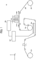
- FIG. 1 is a diagram illustrating an example of general configuration of a liquid discharge apparatus.
- the liquid discharge apparatus is an image forming apparatus 10
- a recording medium is a web 206.
- liquid discharged by the image forming apparatus 10 is ink.
- a direction in which the recording medium is conveyed is the “conveyance direction Y".
- the conveyance direction Y is a left or right direction in FIG. 1 .
- the recording medium is conveyed from the "upstream side” to the “downstream side”. Therefore, in FIG. 1 , the right side is the upstream side, and the left side is the downstream side.
- a direction perpendicular to the conveyance direction Y is referred to as the “perpendicular direction X”.
- a direction vertical to the conveyance direction Y, that is to say a surface of the recording medium, is referred to as the "vertical direction Z".
- the image forming apparatus 10 uses a head 210 to perform inkjet image formation.
- the head 210 includes four heads that include a K head 210K, a C head 210C, an M head 210M, and a Y head 210Y that align in this order from the upstream side to the downstream side.
- the K head 210K, the C head 210C, the M head 210M, and the Y head 210Y may be collectively referred to as the "head 210".
- the image forming apparatus 10 includes an unwinder 201, the head 210, a dryer 203, a reading device 204, a rewinder 205, a superior device 207, an engine 208, and the like.
- the unwinder 201 is a sheet feeder that rolls out and supplies the web 206 that is roll-shaped.
- the rewinder 205 is an accommodation device that rewinds and accommodates the web 206.
- the web 206 is a long sheet. As illustrated, the web 206 is conveyed from the unwinder 201 that is upstream to the rewinder 205 that is downstream. The web 206 is conveyed by, for example, actuators, such as conveyance rollers, and mechanical components.
- the head 210 includes a plurality of nozzles.
- the head 210 discharges ink from the nozzles to the web 206 conveyed directly under the head 210 to perform image formation.
- the dryer 203 dries the web 206.
- the dryer 203 dries the web 206 with a heat drum that is in contact with the web 206.
- the reading device 204 is, for example, a scanner. Therefore, the reading device 204 captures the web 206 to generate image data and the like.
- the image forming apparatus 10 may include a device not described above.
- the image forming apparatus 10 may include, for example, a device for forming an image on the back side, or a device for performing aftertreatment.
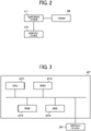
- FIG. 2 is a diagram illustrating an example of coupling of an information processing device and the like.
- the engine 208, a display device 209, and the like are coupled to the superior device 207.
- the superior device 207 is, for example, an information processing device that has a following hardware configuration.
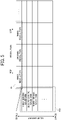
- FIG. 3 is a diagram illustrating an example of hardware configuration of the information processing device.
- the superior device 207 includes hardware, such as a central processing unit (hereinafter referred to as the "CPU 2071”), read-only memory (hereinafter referred to as the "ROM 2072”), random-access memory (hereinafter referred to as the "RAM 2073”), and a hard disk drive (hereinafter referred to as the "HDD 2074").
- CPU 2071 central processing unit
- ROM 2072 read-only memory
- RAM 2073 random-access memory
- HDD 2074 hard disk drive
- the CPU 2071 is an example of an computing device and a control device.
- the ROM 2072, the RAM 2073, and the HDD 2074 are an example of a storage device.
- An output device such as the display device 209, and the like are also coupled to the superior device 207 through interfaces.
- An input device and an external device may also be coupled to the superior device 207 through interfaces.
- the display device 209 is an example of an output device that outputs a processing result and the like.
- the information processing device is not limited to the illustrated hardware configuration.
- the information processing device may include the computing device, the control device, the storage device, the input device, the output device, an auxiliary device, or the like outside or inside the information processing apparatus.
- the superior device 207 is a digital front end (that may be referred to as a "DFE"). More specifically, the superior device 207 performs raster image processor (RIP) processing and the like. Further, the superior device 207 generates data for performing image formation (hereinafter referred to as the "control data") and the like, on the basis of job data and settings of a host device.
- DFE digital front end
- RIP raster image processor
- control data data for performing image formation
- the control data includes information, such as driving waveforms selected in processing for adjusting an image, and the like.
- the control data also includes information on a result of adjustment of nozzle alignment spaces.
- the control data also includes information on printing conditions that include a result of adjustment of gradation.
- the printing conditions are, for example, information, such as printing forms, printing types, information regarding sheet feeding, information regarding sheet ejection, information about recording media, the order of printing of the sides, sizes of recording media, a data amount of image data, resolution, gradation, colors, and the number of pages.
- the engine 208 controls the head 210 and the like to perform processing, such as image formation.
- the image forming apparatus 10 is not limited to the configurations illustrated in FIGS. 1 to 3 .
- the image forming apparatus 10 may include an information processing device not described above, and the like. Therefore, in the image forming apparatus 10, a device except the superior device 207 may perform processing.
- FIG. 4 is a flowchart illustrating a whole processing example.
- step S0401 the liquid discharge apparatus inputs a plurality of driving waveforms. Therefore, on the basis of the driving waveforms input in step S0401, the liquid discharge apparatus discharges liquid.
- step S0402 the liquid discharge apparatus acquires first data.
- the first data is data preliminarily acquired by forming a pattern with the driving waveforms.
- the pattern formed to acquire the first data is referred to as the "standard pattern”.
- first dots Dots that constitute the standard pattern are referred to as the "first dots”.
- the diameter of the first dots is referred to as the “first dot diameter”.
- the first data is, for example, a parameter, such as a numerical value that indicates the first dot diameter.
- the first data may be of a form except a numerical value that indicates the first dot diameter.
- the first data may be, for example, image data or the like that indicates the first dots. Therefore, the first data may be a numerical value or the like input by input operation of a user, or may be acquired from a result of image analysis or the like of the standard pattern. If image data is used in this way, an image of first dots indicated by the image data is analyzed to acquire a parameter for the first data. Therefore, the first data may be image data or the like that indicates dots as a "sample", or may be a numerical value or the like input by a user.
- step S0403 the liquid discharge apparatus discharges liquid to a recording medium to form a test pattern.
- step S0404 the liquid discharge apparatus generates second data.
- the second data is data generated on the basis of a result of reading the test pattern formed in step S0403.
- dots that constitute the test pattern are referred to as the "second dots”.
- the diameter of the second dots is referred to as the "second dot diameter”.
- step S0405 the liquid discharge apparatus compares the first data with the second data.
- step S0406 the liquid discharge apparatus selects a driving waveform on the basis of the comparison result.
- the above-described processing may be performed after selecting resolution (that is to say, a minimum pixel unit of an image).
- resolution that is to say, a minimum pixel unit of an image.
- usable driving waveforms and the like may be specified.
- the resolution may be selected with a user interface (UI) according to an application or the like.
- UI user interface
- the liquid discharge apparatus may correct nozzle alignment spaces, liquid discharge timings, the density, the gradation, or the combination of the nozzle alignment spaces, the liquid discharge timings, the density, and the gradation. For example, if the density is corrected, the variation in the density of each liquid discharge apparatus, the variation in the density of the front and the back, or the like is restricted to make the characteristics of the density and the gradation harmonize with each other.
- the liquid discharge apparatus To correct the gradation, the liquid discharge apparatus first calculates the density at nozzle intervals. Then the liquid discharge apparatus makes an adjustment to allow the densities to be the average density. In this way, the adjustment is made to decrease density unevenness in the head 210. Alternatively, the liquid discharge apparatus adjusts a gradation value or the like of each of the K head 210K, the C head 210C, the M head 210M, and the Y head 210Y to decrease color differences or the like between the K head 210K, the C head 210C, the M head 210M, and the Y head 210Y.
- the liquid discharge apparatus improves the image quality.
- FIG. 5 is a table illustrating an example of input of a plurality of driving waveforms 100 and the like.
- the plurality of driving waveforms 100 includes a "first driving waveform”, a "second driving waveform”, and a "third driving waveform”.
- the amount of discharged liquid is the smallest.
- the amount of discharged liquid is the largest.
- resolution 101 can be selected from “first resolution”, “second resolution”, and “third resolution”.
- the first resolution is the highest resolution
- the third resolution is the lowest resolution
- a test pattern differs by the combination of the resolution 101 and the driving waveforms 100. If as illustrated, the three driving waveforms 100 and the three types of resolution 101 are used, nine results are obtained.
- the number of the driving waveforms 100 and the number of the types of the resolution 101 are not limited to three.
- the driving waveforms 100 that are usable may be different for each of conditions, such as the resolution 101.
- FIG. 6 is a diagram illustrating an example of a test pattern 102.
- the test pattern 102 is formed on the web 206 with a dot group that is a group of second dots of each of the driving waveforms 100.
- a case is exemplified in which the test pattern 102 is constituted by a "first dot group 1021", a "second dot group 1022", and a "third dot group 1023".
- the first dot group 1021 is a dot group constituted by second dots formed with the first driving waveform.
- the second dot group 1022 is a dot group constituted by second dots formed with the second driving waveform.
- the third dot group 1023 is a dot group constituted by second dots formed with the third driving waveform.
- test pattern 102 is formed with the plurality of driving waveforms 100 that is switched.
- the test pattern 102 may not be formed at once with the plurality of driving waveforms 100 that is switched. That is to say, image formation may be performed a plurality of times to form the test pattern 102.
- the test pattern 102 is not limited to the illustrated configuration.
- the arrangement or the number of second dots may be different from the arrangement or the number of the illustrated second dots.
- second dots may be arranged such that different second dots do not overlie, and the second dots are regularly arranged. The regular arrangement in this way reduces unusable sheets.
- the second dots may be formed one dot by one dot with each of the nozzles.
- the second dots are formed one dot by one dot in this way, the effect of the variation in the discharge amounts in the head 210 and the nozzles is decreased.
- the reading device 204 reads the test pattern 102 to generate image data. Next, the reading device 204 analyzes the image data to generate second data. The procedure of generation of the second data will be described below.
- FIG. 7 is a graph illustrating an example of comparison and selection.
- the second data is dot diameters.
- the second data is generated for each of the types of recording media. More specifically, the recording media is of three types: a first sheet 301, a second sheet 302, and a third sheet 303.
- the first sheet 301 is a recording medium on which liquid is the most likely to be sucked and spread.
- the third sheet 303 is a recording medium on which liquid is the least likely to be sucked and spread.
- the second sheet 302 is a recording medium that has the medium likeliness, between the first sheet 301 and the third sheet 303, of liquid being sucked and spreading on the second sheet 302.
- the test patterns 102 are formed on these recording media to read the test patterns 102 to obtain measurement results, such as an eleventh measurement result 3011, a twelfth measurement result 3012, a thirteenth measurement result 3013, a twenty-first measurement result 3021, a twenty-second measurement result 3022, a twenty-third measurement result 3023, a thirty-first measurement result 3031, a thirty-second measurement result 3032, and a thirty-third measurement result 3033.
- the eleventh measurement result 3011 is a result of measurement of the diameter of second dots formed on the first sheet 301 with the first driving waveform.
- the twelfth measurement result 3012 is a result of measurement of the diameter of second dots formed on the first sheet 301 with the second driving waveform.
- the thirteenth measurement result 3013 is a result of measurement of the diameter of second dots formed on the first sheet 301 with the third driving waveform.
- the twenty-first measurement result 3021 is a result of measurement of the diameter of second dots formed on the second sheet 302 with the first driving waveform.
- the twenty-second measurement result 3022 is a result of measurement of the diameter of second dots formed on the second sheet 302 with the second driving waveform.
- the twenty-third measurement result 3023 is a result of measurement of the diameter of second dots formed on the second sheet 302 with the third driving waveform.
- the thirty-first measurement result 3031 is a result of measurement of the diameter of second dots formed on the third sheet 303 with the first driving waveform.
- the thirty-second measurement result 3032 is a result of measurement of the diameter of second dots formed on the third sheet 303 with the second driving waveform.
- the thirty-third measurement result 3033 is a result of measurement of the diameter of second dots formed on the third sheet 303 with the third driving waveform.
- the dot diameter is calculated considering resolution if the resolution is fixed.
- the dot diameter is likely to be a large value, as indicated by the eleventh measurement result 3011 to the thirteenth measurement result 3013.
- the dot diameter is likely to be a small value even if a liquid amount is large, as indicated by the thirty-first measurement result 3031 to the thirty-third measurement result 3033.
- results of the dot diameters may differ between the types of recording media, or the like even if the driving waveform is the same. Therefore, the test patterns 102 are read to generate the second data that indicates the dot diameters and the like.
- the second data is compared with the first data.
- the first data indicates a threshold 304.
- the threshold 304 is preliminarily set.
- the difference between the threshold 304 and the eleventh measurement result 3011 is the smallest. Therefore, if the first sheet 301 is used, using the first driving waveform optimizes the size. Therefore, if the first sheet 301 is used, the first driving waveform is selected.
- the difference between the threshold 304 and the twenty-second measurement result 3022 is the smallest. Therefore, if the second sheet 302 is used, using the second driving waveform optimizes the size. Therefore, if the second sheet 302 is used, the second driving waveform is selected.
- the third sheet 303 is used, the difference between the threshold 304 and the thirty-third measurement result 3033 is the smallest. Therefore, if the third sheet 303 is used, using the third driving waveform optimizes the size. Therefore, if the third sheet 303 is used, the third driving waveform is selected.
- the optimum size is set by acquiring the first data, such as the threshold 304.
- the liquid discharge apparatus generates and reads the test patterns 102 to generate the second data.
- the liquid discharge apparatus compares the first data with the second data to determine a result the closest to the optimum size. In this way, the liquid discharge apparatus can select a driving waveform that discharges the optimum size.
- the second data is generated as described below.
- FIGS. 8A and 8B are diagrams illustrating an example of generation of the second data.
- the test pattern 102 is read, and image data that indicates a second dot is generated, as illustrated in FIG. 8A , for example.
- the liquid discharge apparatus performs binarization of the image data.
- the liquid discharge apparatus When as illustrated in FIG. 8A , the liquid discharge apparatus performs the binarization, the liquid discharge apparatus can recognize an area where liquid is applied (hereinafter referred to as the "applied area 402") and an area where liquid is not applied (hereinafter referred to as the "blank area 401").
- the binarization for recognizing the blank area 401 and the applied area 402 a threshold or the like may be set considering the color of the recording medium, the type of the liquid, and the like.
- the area of the applied area 402 is determined from, for example, a count value of pixels that constitute the applied area 402 (hereinafter referred to as the "count value").
- the area of the one pixel is determined from, for example, resolution. Therefore, the area may be determined by the result of multiplication of the area of a pixel unit determined by resolution, by a count value.
- the second data that is to say a dot diameter
- the second data may be generated on the basis of a count value, the area, or the like.
- roundness that makes a second dot a perfect circle, or the like may be used.
- FIG. 8B is a diagram illustrating an example in which the second dot illustrated in FIG. 8A is made to be a perfect circle.
- a second dot may be a shape that is not a perfect circle, such as an ellipse illustrated in FIG. 8A , for example.
- the liquid discharge apparatus may calculate the diameter of the second dot supposed to be a perfect circle (hereinafter referred to as the "third dot diameter 403"). More specifically, the third dot diameter 403 is calculated by the following Expression (1) or the like.
- third dot diameter ⁇ 4 ⁇ area / ⁇
- the "area” is the result of multiplication of the area of a pixel unit determined by resolution, by a count value.
- the third dot diameter 403 calculated with Expression (1) above may be used for the second data.
- the second data may be a Feret diameter (also referred to as a "projection width” or the like) calculated on the basis of the result of binarization.
- the second data may be a statistical value or the like determined by statistical processing, such as average.
- the test pattern 102 is constituted by a plurality of second dots, as illustrated in FIG. 6 .
- the plurality of second dots is objects of reading, and a plurality of reading results is acquired.
- the statistical value is, for example, the average value, the median, or the maximum value. Using such a statistical value decreases the effect of the bias of second dots, and the like.
- second dots as objects of the statistical processing may be selected. For example, it may be determined that a second dot a portion of which is lost is an exclusion object. The second dot that receives the determination that the second dot is an exclusion object may be excluded from calculation of a statistical value.
- the roundness of each of second dots is calculated.
- Exclusion objects are determined by comparing the roundness of each of the second dots with a set value preliminarily set.
- the roundness is a value that is closer to "1" as the shape is closer to a perfect circle.
- the set value is, for example, a value from 0.5 to 0.6 preliminarily set. In such a case, a second dot that has roundness smaller than the set value is an exclusion object.
- the roundness may be calculated by a calculation method defined in Japanese Industrial Standard (JIS) B 0621-1984 or the like.
- an exclusion object may be a second dot that receives a determination that the second dot is abnormal, with an average value ⁇ 3 ⁇ (" ⁇ " is the standard deviation) as the standard.
- a liquid discharge system 20 that includes the liquid discharge apparatus may have the following configuration.
- FIG. 9 is a diagram illustrating a general configuration of a modification.
- the liquid discharge system 20 includes, for example, a sheet feeder 21, a treatment agent liquid application apparatus 22, a first inkjet apparatus 23 as an example of the liquid discharge apparatus, a reversing apparatus 24, and a second inkjet apparatus 25.
- a recording medium is, for example, a rolled sheet that is continuous stationery.
- the sheet feeder 21 conveys the recording medium to the treatment agent liquid application apparatus 22.
- the treatment agent liquid application apparatus 22 performs pretreatment to the recording medium.
- the treatment agent liquid application apparatus 22 applies treatment agent liquid to the front and back of the recording medium.
- the first inkjet apparatus 23 discharges liquid to the recording medium to perform image formation and the like.
- the first inkjet apparatus 23 forms an image indicated by image data, on the front of the recording medium.
- the reversing apparatus 24 turns over the recording medium.
- the second inkjet apparatus 25 discharges liquid to the recording medium to perform image formation and the like.
- the second inkjet apparatus 25 forms an image indicated by image data, on the back of the recording medium.
- the liquid discharge system 20 may not have the illustrated configuration.
- the liquid discharge system 20 may additionally include an apparatus that performs pretreatment or aftertreatment except the illustrated types of pretreatment and aftertreatment.
- the number of the liquid discharge apparatus may be one or three or more.
- FIGS. 10 is a diagram illustrating an example of configuration that detects the position of a recording medium with an image sensor 52.
- the liquid discharge apparatus may have, for example, the following configuration.
- the first inkjet apparatus 23 has a hardware configuration that includes the image sensor 52.
- the image sensor 52 captures a conveyed recording medium to generate image data. More specifically, the image sensor 52 captures the front of the recording medium at preset intervals.
- Part (B) of FIG. 10 is a diagram schematically illustrating intervals at which the image sensor 52 performs the capture.
- image data in the order of the capture is referred to as "first image data IMG1", “second image data IMG2”, “third image data IMG3”, “fourth image data IMG4", and ....
- the first inkjet apparatus 23 performs frequency analysis processing, such as fast Fourier transform (FFT), to the image data.
- FFT fast Fourier transform
- the first inkjet apparatus 23 uses the results of the frequency analysis processing to calculate a peak of image correlation between two pieces of image data.
- Part (C) of FIG. 10 is a diagram illustrating an example of the frequency analysis result. More specifically, the first inkjet apparatus 23 generates a "first analysis result F12", on the basis of the first image data IMG1 and the second image data IMG2. Similarly, the first inkjet apparatus 23 generates a "second analysis result F23", on the basis of the second image data IMG2 and the third image data IMG3. Next, the first inkjet apparatus 23 generates a "third analysis result F34", on the basis of the third image data IMG3 and the fourth image data IMG4. A peak is calculated in each of the analysis results.
- the first inkjet apparatus 23 calculates a conveyance amount. More specifically, the first inkjet apparatus 23 compares the positions of the peaks with each other to calculate a change in the position of the pattern on the surface of a recording medium. On the basis of such results, the first inkjet apparatus 23 generates a pulse at, for example, each time when the conveyance amount reaches a fixed value.
- such a configuration allows the first inkjet apparatus 23 to generate a signal that indicates the position change, the conveyance speed, the combination of the position change and the conveyance speed, or the like.
- the configuration that detects the position of a recording medium with the image sensor 52 decreases work for preliminarily preparing a slit or the like in a recording medium.
- the comparison may be performed by processing except the processing described above.
- the determination of similarity with artificial intelligence (AI) or the like may be performed for the comparison.
- first data is image data or the like that indicates a standard pattern.
- Second data is image data or the like read from second dots.
- the AI is preliminarily trained with the first data as training data. Such a configuration allows the AI to compare the first data with the second data. That is to say, the AI allows the liquid discharge apparatus to select a driving waveform that forms dots the closest to a dot indicated by the first data.
- FIG. 11 is a diagram illustrating a functional-configuration example.
- the liquid discharge apparatus includes, for example, a discharge unit 10F1, a control unit 10F2, an input unit 10F3, an acquisition unit 10F4, a reading unit 10F5, a comparison unit 10F6, and a selection unit 10F7.
- the discharge unit 10F1 discharges liquid to a recording medium to perform a discharge procedure that forms a test pattern.
- the discharge unit 10F1 is implemented by, for example, the head 210 and the like.
- the control unit 10F2 performs a control procedure that makes the discharge unit 10F1 discharge liquid according to a driving waveform.
- the control unit 10F2 is implemented by, for example, the engine 208 and the like.
- the input unit 10F3 performs an input procedure that inputs a plurality of driving waveforms.
- the input unit 10F3 is implemented by, for example, the superior device 207 and the like.
- the acquisition unit 10F4 performs an acquisition procedure that acquires first data.
- the acquisition unit 10F4 is implemented by, for example, the superior device 207 and the like.
- the reading unit 10F5 reads a test pattern to perform a reading procedure that generates second data.
- the reading unit 10F5 is implemented by, for example, the reading device 204 and the like.
- the comparison unit 10F6 performs a comparison procedure that compares the second data with the first data.
- the comparison unit 10F6 is implemented by, for example, the superior device 207 and the like.
- the selection unit 10F7 On the basis of the result of the comparison by the comparison unit 10F6, the selection unit 10F7 performs a selection procedure that selects a driving waveform that makes the smallest difference between the second data and the first data.
- the selection unit 10F7 is implemented by, for example, the superior device 207 and the like.
- a liquid discharge apparatus that has a combination of resolution and a conveyance speed (that may be referred to as a "line speed") according to a printing application.
- the conveyance speed is set high, and the resolution is set low to increase the productivity, for example.
- the conveyance speed is set low, and the resolution is set high.
- the liquid discharge apparatus makes liquid that has a larger size impact on a recording medium to deal with filling the image. Therefore, the optimum size exists for each of the conditions, such as the resolution.
- the size is smaller than the optimum size, the image is insufficiently filled. Thus, insufficient density, such as insufficient solid printing, and the like occur. On the other hand, when the size is larger than the optimum size, the granularity becomes poor.
- the characteristics of recording media differ between the types of the recording media, and the like.
- the size is affected by, for example, the characteristics, such as easiness of liquid being sucked and spreading, an outer air, humidity, or the like.
- the size is particularly often much affected by the characteristics of a recording medium. Therefore, to optimize the size, the liquid discharge apparatus forms a test pattern. When the test pattern is formed in this way, the size of discharged liquid is optimized.
- the liquid discharge apparatus optimizes the size to improve the density characteristic, the granularity, or the like to improve the image quality.
- the liquid discharge method described above may be implemented by, for example, a program. That is to say, the liquid discharge method is a method executed by a computer that allows the computing device, the storage device, the input device, the output device, and the control device to cooperate on the basis of the program.
- the program may be written into the storage device, a storage medium, or the like and distributed, or may be distributed via an electrical communication line or the like.
- each of the devices described above may not be one device. That is to say, each of the devices may be a system or the like that includes a plurality of devices.
- the image forming apparatus may be, for example, a commercial printing machine (for example, a large-scale electrophotographic printer or an inkjet printer).
- the recording medium is, for example, a sheet (that may be referred to as a "plain sheet of paper" or the like).
- the recording medium may be a coated sheet, a label sheet, or the like except the sheet, or an overhead projector sheet, a film, a flexible thin plate, or the like.
- the recording medium may be a rolled sheet or the like.
- the material of the recording medium only needs to have a material property such as ink or paint, such as toner, being capable of sticking to the material, being capable of temporarily sticking to the material, being capable of sticking and adhering to the material, or being capable of sticking to and permeating the material.
- a material property such as ink or paint, such as toner
- the recording medium is a sheet, a film, a medium to be recorded, such as cloth, an electronic board, an electronic component, such as a piezoelectric element (that may be referred to as a "piezoelectric component” or the like), a powder material layer (that may be referred to as a "powder layer” or the like), an organ model, a cell for inspection, or the like.
- a piezoelectric element that may be referred to as a "piezoelectric component” or the like
- a powder material layer that may be referred to as a "powder layer” or the like
- organ model that may be referred to as a cell for inspection, or the like.
- the material property of the recording medium may be paper, thread, fiber, fabric, leather, metal, plastic, glass, wood, or ceramics to which paint can stick, or the combination of paper, thread, fiber, fabric, leather, metal, plastic, glass, wood, and ceramics to which paint can stick.
- the liquid is not limited to ink but may not be ink if the liquid has a material property of sticking to the recording medium.
- the present invention can be implemented in any convenient form, for example using dedicated hardware, or a mixture of dedicated hardware and software.
- the present invention may be implemented as computer software implemented by one or more networked processing apparatuses.
- the processing apparatuses include any suitably programmed apparatuses such as a general purpose computer, personal digital assistant, mobile telephone (such as a WAP or 3G-compliant phone) and so on. Since the present invention can be implemented as software, each and every aspect of the present invention thus encompasses computer software implementable on a programmable device.
- the computer software can be provided to the programmable device using any conventional carrier medium (carrier means).
- the carrier medium includes a transient carrier medium such as an electrical, optical, microwave, acoustic or radio frequency signal carrying the computer code.
- transient medium is a TCP/IP signal carrying computer code over an IP network, such as the Internet.
- the carrier medium may also include a storage medium for storing processor readable code such as a floppy disk, hard disk, CD-ROM, magnetic tape device or solid state memory device.
Landscapes
- Engineering & Computer Science (AREA)
- Quality & Reliability (AREA)
- Ink Jet (AREA)
- Particle Formation And Scattering Control In Inkjet Printers (AREA)
Abstract
Description
- Embodiments of the present disclosure relate to a liquid discharge apparatus, a liquid discharge method, and a carrier medium.
- A technique is known in which an inkjet head discharges liquid, such as ink, to form an image.
- For example, first, an inkjet recording apparatus forms dots at predetermined intervals to form a test pattern on a recording medium. Then, the inkjet recording apparatus measures the density of the dots. Next, on the basis of the measurement result, the inkjet recording apparatus determines the type of the recording medium. Such a technique is known of forming a test pattern to accurately determine the type of a recording medium (see, for example,
Japanese Unexamined Patent Application Publication No. 2007-152670 - The technique disclosed in
Japanese Unexamined Patent Application Publication No. 2007-152670 - It is an object of the present disclosure to provide the optimum size of discharged liquid on the basis of a test pattern.
- To solve the problem described above, according to an embodiment of the present disclosure, a liquid discharge apparatus includes a discharge unit, a control unit, an input unit, an acquisition unit, a reading unit, a comparison unit, and a selection unit. The discharge unit discharges liquid to a recording medium to form a test pattern. The control unit causes the discharge unit to discharge the liquid according to a driving waveform. The input unit inputs a plurality of driving waveforms. The acquisition unit acquires first data indicating a standard pattern that corresponds to the driving waveform and is formed with the driving waveform or indicating a parameter of the standard pattern. The reading unit reads the test pattern to generate second data. The comparison unit compares the second data with the first data. The selection unit selects a driving waveform generating a smallest difference between the second data and the first data, based on a result of comparison of the second data with the first data by the comparison unit.
- According to another embodiment of the present disclosure, there is provided a liquid discharge method to be performed by a liquid discharge apparatus. The liquid discharge method includes discharging, controlling, inputting, acquiring, reading, comparing, and selecting. The discharging discharges liquid by a liquid discharge apparatus to a recording medium to form a test pattern. The controlling controls the liquid discharge apparatus to discharge the liquid according to a driving waveform. The inputting inputs a plurality of driving waveforms. The acquiring acquires first data that indicates a standard pattern that corresponds to the driving waveform and is formed with the driving waveform, or indicates a parameter of the standard pattern. The reading reads the test pattern to generate second data. The comparing compares the second data with the first data. The selecting selects a driving waveform generating a smallest difference between the second data and the first data, based on a result of comparison of the second data with the first data by the comparing.
- According to still another embodiment of the present disclosure, there is provided a carrier medium for carrying a program code for causing a computer to execute the liquid discharge method.
- According to embodiments of the present disclosure, the optimum size of discharged liquid can be obtained based on a test pattern.
- A more complete appreciation of the disclosure and many of the attendant advantages and features thereof can be readily obtained and understood from the following detailed description with reference to the accompanying drawings, wherein:
-
FIG. 1 is a diagram illustrating an example of a general configuration of a liquid discharge apparatus; -
FIG. 2 is a diagram illustrating an example of coupling of an information processing device and the like; -
FIG. 3 is a diagram illustrating an example of hardware configuration of the information processing device; -
FIG. 4 is a flowchart illustrating a whole processing example; -
FIG. 5 is a table illustrating an example of input of a plurality of driving waveforms and the like; -
FIG. 6 is a diagram illustrating an example of a test pattern; -
FIG. 7 is a graph illustrating an example of comparison and selection; -
FIG. 8A is a diagram illustrating an example of generation of second data; -
FIG. 8B is a diagram illustrating an example of generation of the second data; -
FIG. 9 is a diagram illustrating a general configuration of a modification; -
FIG. 10 is a diagram illustrating an example of configuration that detects the position of the recording medium with the image sensor; and -
FIG. 11 is a diagram illustrating a functional-configuration example. - Hereinafter, specific examples will be described with reference to the accompanying drawings. Note that embodiments are not limited to the specific examples described below.
- The terminology used herein is for the purpose of describing particular embodiments only and is not intended to be limiting of the present invention. As used herein, the singular forms "a", "an" and "the" are intended to include the plural forms as well, unless the context clearly indicates otherwise.
- In describing embodiments illustrated in the drawings, specific terminology is employed for the sake of clarity. However, the disclosure of this specification is not intended to be limited to the specific terminology so selected and it is to be understood that each specific element includes all technical equivalents that have a similar function, operate in a similar manner, and achieve a similar result.
-
FIG. 1 is a diagram illustrating an example of general configuration of a liquid discharge apparatus. Hereinafter, an example in which the liquid discharge apparatus is animage forming apparatus 10 will be described. In the example described below, a recording medium is aweb 206. In the example described below, liquid discharged by theimage forming apparatus 10 is ink. - Hereinafter, a direction in which the recording medium is conveyed is the "conveyance direction Y". The conveyance direction Y is a left or right direction in
FIG. 1 . In the description below, the recording medium is conveyed from the "upstream side" to the "downstream side". Therefore, inFIG. 1 , the right side is the upstream side, and the left side is the downstream side. A direction perpendicular to the conveyance direction Y is referred to as the "perpendicular direction X". A direction vertical to the conveyance direction Y, that is to say a surface of the recording medium, is referred to as the "vertical direction Z". - The
image forming apparatus 10 uses ahead 210 to perform inkjet image formation. Hereinafter, an example will be described in which thehead 210 includes four heads that include aK head 210K, aC head 210C, anM head 210M, and aY head 210Y that align in this order from the upstream side to the downstream side. TheK head 210K, theC head 210C, theM head 210M, and theY head 210Y may be collectively referred to as the "head 210". - The
image forming apparatus 10 includes anunwinder 201, thehead 210, adryer 203, areading device 204, arewinder 205, asuperior device 207, anengine 208, and the like. - The
unwinder 201 is a sheet feeder that rolls out and supplies theweb 206 that is roll-shaped. - The
rewinder 205 is an accommodation device that rewinds and accommodates theweb 206. - The
web 206 is a long sheet. As illustrated, theweb 206 is conveyed from theunwinder 201 that is upstream to therewinder 205 that is downstream. Theweb 206 is conveyed by, for example, actuators, such as conveyance rollers, and mechanical components. - The
head 210 includes a plurality of nozzles. Thehead 210 discharges ink from the nozzles to theweb 206 conveyed directly under thehead 210 to perform image formation. - The
dryer 203 dries theweb 206. For example, thedryer 203 dries theweb 206 with a heat drum that is in contact with theweb 206. - The
reading device 204 is, for example, a scanner. Therefore, thereading device 204 captures theweb 206 to generate image data and the like. - The
image forming apparatus 10 may include a device not described above. Theimage forming apparatus 10 may include, for example, a device for forming an image on the back side, or a device for performing aftertreatment. -
FIG. 2 is a diagram illustrating an example of coupling of an information processing device and the like. For example, theengine 208, adisplay device 209, and the like are coupled to thesuperior device 207. - The
superior device 207 is, for example, an information processing device that has a following hardware configuration. -
FIG. 3 is a diagram illustrating an example of hardware configuration of the information processing device. For example, thesuperior device 207 includes hardware, such as a central processing unit (hereinafter referred to as the "CPU 2071"), read-only memory (hereinafter referred to as the "ROM 2072"), random-access memory (hereinafter referred to as the "RAM 2073"), and a hard disk drive (hereinafter referred to as the "HDD 2074"). - The
CPU 2071 is an example of an computing device and a control device. - The
ROM 2072, theRAM 2073, and theHDD 2074 are an example of a storage device. - An output device, such as the
display device 209, and the like are also coupled to thesuperior device 207 through interfaces. An input device and an external device may also be coupled to thesuperior device 207 through interfaces. - The
display device 209 is an example of an output device that outputs a processing result and the like. - Note that the information processing device is not limited to the illustrated hardware configuration. For example, the information processing device may include the computing device, the control device, the storage device, the input device, the output device, an auxiliary device, or the like outside or inside the information processing apparatus.
- The
superior device 207 is a digital front end (that may be referred to as a "DFE"). More specifically, thesuperior device 207 performs raster image processor (RIP) processing and the like. Further, thesuperior device 207 generates data for performing image formation (hereinafter referred to as the "control data") and the like, on the basis of job data and settings of a host device. - The control data includes information, such as driving waveforms selected in processing for adjusting an image, and the like. The control data also includes information on a result of adjustment of nozzle alignment spaces. The control data also includes information on printing conditions that include a result of adjustment of gradation.
- The printing conditions are, for example, information, such as printing forms, printing types, information regarding sheet feeding, information regarding sheet ejection, information about recording media, the order of printing of the sides, sizes of recording media, a data amount of image data, resolution, gradation, colors, and the number of pages.
- On the basis of the control data and the like sent by the
superior device 207, theengine 208 controls thehead 210 and the like to perform processing, such as image formation. - The
image forming apparatus 10 is not limited to the configurations illustrated inFIGS. 1 to 3 . For example, theimage forming apparatus 10 may include an information processing device not described above, and the like. Therefore, in theimage forming apparatus 10, a device except thesuperior device 207 may perform processing. -
FIG. 4 is a flowchart illustrating a whole processing example. - In step S0401, the liquid discharge apparatus inputs a plurality of driving waveforms. Therefore, on the basis of the driving waveforms input in step S0401, the liquid discharge apparatus discharges liquid.
- In step S0402, the liquid discharge apparatus acquires first data.
- The first data is data preliminarily acquired by forming a pattern with the driving waveforms. Hereinafter, the pattern formed to acquire the first data is referred to as the "standard pattern".
- Dots that constitute the standard pattern are referred to as the "first dots". The diameter of the first dots is referred to as the "first dot diameter".
- The first data is, for example, a parameter, such as a numerical value that indicates the first dot diameter. However, the first data may be of a form except a numerical value that indicates the first dot diameter. The first data may be, for example, image data or the like that indicates the first dots. Therefore, the first data may be a numerical value or the like input by input operation of a user, or may be acquired from a result of image analysis or the like of the standard pattern. If image data is used in this way, an image of first dots indicated by the image data is analyzed to acquire a parameter for the first data. Therefore, the first data may be image data or the like that indicates dots as a "sample", or may be a numerical value or the like input by a user.
- In step S0403, the liquid discharge apparatus discharges liquid to a recording medium to form a test pattern.
- In step S0404, the liquid discharge apparatus generates second data.
- The second data is data generated on the basis of a result of reading the test pattern formed in step S0403. Hereinafter, dots that constitute the test pattern are referred to as the "second dots". The diameter of the second dots is referred to as the "second dot diameter".
- In step S0405, the liquid discharge apparatus compares the first data with the second data.
- In step S0406, the liquid discharge apparatus selects a driving waveform on the basis of the comparison result.
- The above-described processing may be performed after selecting resolution (that is to say, a minimum pixel unit of an image). According to the resolution, usable driving waveforms and the like may be specified. For example, the resolution may be selected with a user interface (UI) according to an application or the like.
- Further, the liquid discharge apparatus may correct nozzle alignment spaces, liquid discharge timings, the density, the gradation, or the combination of the nozzle alignment spaces, the liquid discharge timings, the density, and the gradation. For example, if the density is corrected, the variation in the density of each liquid discharge apparatus, the variation in the density of the front and the back, or the like is restricted to make the characteristics of the density and the gradation harmonize with each other.
- To correct the gradation, the liquid discharge apparatus first calculates the density at nozzle intervals. Then the liquid discharge apparatus makes an adjustment to allow the densities to be the average density. In this way, the adjustment is made to decrease density unevenness in the
head 210. Alternatively, the liquid discharge apparatus adjusts a gradation value or the like of each of theK head 210K, theC head 210C, theM head 210M, and theY head 210Y to decrease color differences or the like between theK head 210K, theC head 210C, theM head 210M, and theY head 210Y. - When such correction and the like described above are performed, the liquid discharge apparatus improves the image quality.
-
FIG. 5 is a table illustrating an example of input of a plurality of drivingwaveforms 100 and the like. Hereinafter, the plurality of drivingwaveforms 100 includes a "first driving waveform", a "second driving waveform", and a "third driving waveform". - In this example, when the first driving waveform is used, the amount of discharged liquid is the smallest. When the third driving waveform is used, the amount of discharged liquid is the largest.
- Hereinafter,
resolution 101 can be selected from "first resolution", "second resolution", and "third resolution". - In this example, the first resolution is the highest resolution, and the third resolution is the lowest resolution.
- A test pattern differs by the combination of the
resolution 101 and the drivingwaveforms 100. If as illustrated, the three drivingwaveforms 100 and the three types ofresolution 101 are used, nine results are obtained. The number of the drivingwaveforms 100 and the number of the types of theresolution 101 are not limited to three. The drivingwaveforms 100 that are usable may be different for each of conditions, such as theresolution 101. -
FIG. 6 is a diagram illustrating an example of atest pattern 102. For example, thetest pattern 102 is formed on theweb 206 with a dot group that is a group of second dots of each of the drivingwaveforms 100. Hereinafter, a case is exemplified in which thetest pattern 102 is constituted by a "first dot group 1021", a "second dot group 1022", and a "third dot group 1023". - The
first dot group 1021 is a dot group constituted by second dots formed with the first driving waveform. - The
second dot group 1022 is a dot group constituted by second dots formed with the second driving waveform. - The
third dot group 1023 is a dot group constituted by second dots formed with the third driving waveform. - In this way, the
test pattern 102 is formed with the plurality of drivingwaveforms 100 that is switched. Thetest pattern 102 may not be formed at once with the plurality of drivingwaveforms 100 that is switched. That is to say, image formation may be performed a plurality of times to form thetest pattern 102. - The
test pattern 102 is not limited to the illustrated configuration. For example, the arrangement or the number of second dots may be different from the arrangement or the number of the illustrated second dots. However, second dots may be arranged such that different second dots do not overlie, and the second dots are regularly arranged. The regular arrangement in this way reduces unusable sheets. - The second dots may be formed one dot by one dot with each of the nozzles. When the second dots are formed one dot by one dot in this way, the effect of the variation in the discharge amounts in the
head 210 and the nozzles is decreased. - After the
test pattern 102 is formed as described above, thereading device 204 reads thetest pattern 102 to generate image data. Next, thereading device 204 analyzes the image data to generate second data. The procedure of generation of the second data will be described below. -
FIG. 7 is a graph illustrating an example of comparison and selection. Hereinafter, the second data is dot diameters. For example, the second data is generated for each of the types of recording media. More specifically, the recording media is of three types: afirst sheet 301, asecond sheet 302, and athird sheet 303. - For example, of the three types, the
first sheet 301 is a recording medium on which liquid is the most likely to be sucked and spread. Of the three types, thethird sheet 303 is a recording medium on which liquid is the least likely to be sucked and spread. Thesecond sheet 302 is a recording medium that has the medium likeliness, between thefirst sheet 301 and thethird sheet 303, of liquid being sucked and spreading on thesecond sheet 302. - The
test patterns 102 are formed on these recording media to read thetest patterns 102 to obtain measurement results, such as aneleventh measurement result 3011, atwelfth measurement result 3012, athirteenth measurement result 3013, a twenty-first measurement result 3021, a twenty-second measurement result 3022, a twenty-third measurement result 3023, a thirty-first measurement result 3031, a thirty-second measurement result 3032, and a thirty-third measurement result 3033. - The
eleventh measurement result 3011 is a result of measurement of the diameter of second dots formed on thefirst sheet 301 with the first driving waveform. - The
twelfth measurement result 3012 is a result of measurement of the diameter of second dots formed on thefirst sheet 301 with the second driving waveform. - The
thirteenth measurement result 3013 is a result of measurement of the diameter of second dots formed on thefirst sheet 301 with the third driving waveform. - The twenty-
first measurement result 3021 is a result of measurement of the diameter of second dots formed on thesecond sheet 302 with the first driving waveform. - The twenty-
second measurement result 3022 is a result of measurement of the diameter of second dots formed on thesecond sheet 302 with the second driving waveform. - The twenty-
third measurement result 3023 is a result of measurement of the diameter of second dots formed on thesecond sheet 302 with the third driving waveform. - The thirty-
first measurement result 3031 is a result of measurement of the diameter of second dots formed on thethird sheet 303 with the first driving waveform. - The thirty-
second measurement result 3032 is a result of measurement of the diameter of second dots formed on thethird sheet 303 with the second driving waveform. - The thirty-
third measurement result 3033 is a result of measurement of the diameter of second dots formed on thethird sheet 303 with the third driving waveform. - The dot diameter is calculated considering resolution if the resolution is fixed.
- In a case of a recording medium on which liquid is likely to be sucked and spread, such as the
first sheet 301, liquid is likely to be sucked and spread after the impact. Therefore, the dot diameter is likely to be a large value, as indicated by theeleventh measurement result 3011 to thethirteenth measurement result 3013. In a case of a recording medium on which liquid is not likely to be sucked and spread, such as thethird sheet 303, liquid is not likely to be sucked and spread after the impact. Therefore, the dot diameter is likely to be a small value even if a liquid amount is large, as indicated by the thirty-first measurement result 3031 to the thirty-third measurement result 3033. - In this way, results of the dot diameters may differ between the types of recording media, or the like even if the driving waveform is the same. Therefore, the
test patterns 102 are read to generate the second data that indicates the dot diameters and the like. - Next, the second data is compared with the first data. In the illustrated example, the first data indicates a
threshold 304. For example, thethreshold 304 is preliminarily set. - In the illustrated example, if the
first sheet 301 is used, the difference between thethreshold 304 and theeleventh measurement result 3011 is the smallest. Therefore, if thefirst sheet 301 is used, using the first driving waveform optimizes the size. Therefore, if thefirst sheet 301 is used, the first driving waveform is selected. - Similarly, if the
second sheet 302 is used, the difference between thethreshold 304 and the twenty-second measurement result 3022 is the smallest. Therefore, if thesecond sheet 302 is used, using the second driving waveform optimizes the size. Therefore, if thesecond sheet 302 is used, the second driving waveform is selected. - If the
third sheet 303 is used, the difference between thethreshold 304 and the thirty-third measurement result 3033 is the smallest. Therefore, if thethird sheet 303 is used, using the third driving waveform optimizes the size. Therefore, if thethird sheet 303 is used, the third driving waveform is selected. - In this way, the optimum size is set by acquiring the first data, such as the
threshold 304. On the contrary, the liquid discharge apparatus generates and reads thetest patterns 102 to generate the second data. The liquid discharge apparatus compares the first data with the second data to determine a result the closest to the optimum size. In this way, the liquid discharge apparatus can select a driving waveform that discharges the optimum size. - For example, the second data is generated as described below.
-
FIGS. 8A and 8B are diagrams illustrating an example of generation of the second data. First, thetest pattern 102 is read, and image data that indicates a second dot is generated, as illustrated inFIG. 8A , for example. Next, the liquid discharge apparatus performs binarization of the image data. - When as illustrated in
FIG. 8A , the liquid discharge apparatus performs the binarization, the liquid discharge apparatus can recognize an area where liquid is applied (hereinafter referred to as the "appliedarea 402") and an area where liquid is not applied (hereinafter referred to as the "blank area 401"). For the binarization for recognizing theblank area 401 and the appliedarea 402, a threshold or the like may be set considering the color of the recording medium, the type of the liquid, and the like. - The area of the applied
area 402 is determined from, for example, a count value of pixels that constitute the applied area 402 (hereinafter referred to as the "count value"). The area of the one pixel is determined from, for example, resolution. Therefore, the area may be determined by the result of multiplication of the area of a pixel unit determined by resolution, by a count value. - For example, the second data, that is to say a dot diameter, may be generated on the basis of a count value, the area, or the like.
- To generate the second data, roundness that makes a second dot a perfect circle, or the like may be used.
-
FIG. 8B is a diagram illustrating an example in which the second dot illustrated inFIG. 8A is made to be a perfect circle. A second dot may be a shape that is not a perfect circle, such as an ellipse illustrated inFIG. 8A , for example. In such a case, the liquid discharge apparatus may calculate the diameter of the second dot supposed to be a perfect circle (hereinafter referred to as the "third dot diameter 403"). More specifically, thethird dot diameter 403 is calculated by the following Expression (1) or the like.
- In Expression (1) above, the "area" is the result of multiplication of the area of a pixel unit determined by resolution, by a count value. In this way, the
third dot diameter 403 calculated with Expression (1) above may be used for the second data. - The second data may be a Feret diameter (also referred to as a "projection width" or the like) calculated on the basis of the result of binarization.
- The second data may be a statistical value or the like determined by statistical processing, such as average. The
test pattern 102 is constituted by a plurality of second dots, as illustrated inFIG. 6 . In such a case, the plurality of second dots is objects of reading, and a plurality of reading results is acquired. - The statistical value is, for example, the average value, the median, or the maximum value. Using such a statistical value decreases the effect of the bias of second dots, and the like.
- If such statistical processing as described above is performed, second dots as objects of the statistical processing may be selected. For example, it may be determined that a second dot a portion of which is lost is an exclusion object. The second dot that receives the determination that the second dot is an exclusion object may be excluded from calculation of a statistical value.
- More specifically, first, the roundness of each of second dots is calculated. Exclusion objects are determined by comparing the roundness of each of the second dots with a set value preliminarily set. For example, the roundness is a value that is closer to "1" as the shape is closer to a perfect circle. The set value is, for example, a value from 0.5 to 0.6 preliminarily set. In such a case, a second dot that has roundness smaller than the set value is an exclusion object.
- The roundness may be calculated by a calculation method defined in Japanese Industrial Standard (JIS) B 0621-1984 or the like.
- Alternatively, an exclusion object may be a second dot that receives a determination that the second dot is abnormal, with an average value ± 3 σ ("σ" is the standard deviation) as the standard.
- As described above, even if abnormal dots are included, excluding the abnormal dots allows the liquid discharge apparatus to accurately select a driving waveform that provides the optimum size.
- A liquid discharge system 20 that includes the liquid discharge apparatus may have the following configuration.
-
FIG. 9 is a diagram illustrating a general configuration of a modification. The liquid discharge system 20 includes, for example, asheet feeder 21, a treatment agentliquid application apparatus 22, afirst inkjet apparatus 23 as an example of the liquid discharge apparatus, a reversingapparatus 24, and asecond inkjet apparatus 25. - A recording medium is, for example, a rolled sheet that is continuous stationery.
- The
sheet feeder 21 conveys the recording medium to the treatment agentliquid application apparatus 22. - The treatment agent
liquid application apparatus 22 performs pretreatment to the recording medium. For example, the treatment agentliquid application apparatus 22 applies treatment agent liquid to the front and back of the recording medium. - The
first inkjet apparatus 23 discharges liquid to the recording medium to perform image formation and the like. For example, thefirst inkjet apparatus 23 forms an image indicated by image data, on the front of the recording medium. - The reversing
apparatus 24 turns over the recording medium. - The
second inkjet apparatus 25 discharges liquid to the recording medium to perform image formation and the like. For example, thesecond inkjet apparatus 25 forms an image indicated by image data, on the back of the recording medium. - The liquid discharge system 20 may not have the illustrated configuration. For example, the liquid discharge system 20 may additionally include an apparatus that performs pretreatment or aftertreatment except the illustrated types of pretreatment and aftertreatment. The number of the liquid discharge apparatus may be one or three or more.
-
FIGS. 10 is a diagram illustrating an example of configuration that detects the position of a recording medium with animage sensor 52. The liquid discharge apparatus may have, for example, the following configuration. - As illustrated in part (A) of
FIG. 10 , thefirst inkjet apparatus 23 has a hardware configuration that includes theimage sensor 52. - The
image sensor 52 captures a conveyed recording medium to generate image data. More specifically, theimage sensor 52 captures the front of the recording medium at preset intervals. - Part (B) of
FIG. 10 is a diagram schematically illustrating intervals at which theimage sensor 52 performs the capture. Hereinafter, image data in the order of the capture is referred to as "first image data IMG1", "second image data IMG2", "third image data IMG3", "fourth image data IMG4", and .... - Then the
first inkjet apparatus 23 performs frequency analysis processing, such as fast Fourier transform (FFT), to the image data. Thefirst inkjet apparatus 23 uses the results of the frequency analysis processing to calculate a peak of image correlation between two pieces of image data. - Part (C) of
FIG. 10 is a diagram illustrating an example of the frequency analysis result. More specifically, thefirst inkjet apparatus 23 generates a "first analysis result F12", on the basis of the first image data IMG1 and the second image data IMG2. Similarly, thefirst inkjet apparatus 23 generates a "second analysis result F23", on the basis of the second image data IMG2 and the third image data IMG3. Next, thefirst inkjet apparatus 23 generates a "third analysis result F34", on the basis of the third image data IMG3 and the fourth image data IMG4. A peak is calculated in each of the analysis results. - On the basis of the peaks calculated in this way, the
first inkjet apparatus 23 calculates a conveyance amount. More specifically, thefirst inkjet apparatus 23 compares the positions of the peaks with each other to calculate a change in the position of the pattern on the surface of a recording medium. On the basis of such results, thefirst inkjet apparatus 23 generates a pulse at, for example, each time when the conveyance amount reaches a fixed value. - Similarly as an encoder roller or the like, such a configuration allows the
first inkjet apparatus 23 to generate a signal that indicates the position change, the conveyance speed, the combination of the position change and the conveyance speed, or the like. The configuration that detects the position of a recording medium with theimage sensor 52 decreases work for preliminarily preparing a slit or the like in a recording medium. - The comparison may be performed by processing except the processing described above. For example, the determination of similarity with artificial intelligence (AI) or the like may be performed for the comparison. More specifically, first data is image data or the like that indicates a standard pattern. Second data is image data or the like read from second dots. The AI is preliminarily trained with the first data as training data. Such a configuration allows the AI to compare the first data with the second data. That is to say, the AI allows the liquid discharge apparatus to select a driving waveform that forms dots the closest to a dot indicated by the first data.
-
FIG. 11 is a diagram illustrating a functional-configuration example. The liquid discharge apparatus includes, for example, a discharge unit 10F1, a control unit 10F2, an input unit 10F3, an acquisition unit 10F4, a reading unit 10F5, a comparison unit 10F6, and a selection unit 10F7. - The discharge unit 10F1 discharges liquid to a recording medium to perform a discharge procedure that forms a test pattern. The discharge unit 10F1 is implemented by, for example, the
head 210 and the like. - The control unit 10F2 performs a control procedure that makes the discharge unit 10F1 discharge liquid according to a driving waveform. The control unit 10F2 is implemented by, for example, the
engine 208 and the like. - The input unit 10F3 performs an input procedure that inputs a plurality of driving waveforms. The input unit 10F3 is implemented by, for example, the
superior device 207 and the like. - The acquisition unit 10F4 performs an acquisition procedure that acquires first data. The acquisition unit 10F4 is implemented by, for example, the
superior device 207 and the like. - The reading unit 10F5 reads a test pattern to perform a reading procedure that generates second data. The reading unit 10F5 is implemented by, for example, the
reading device 204 and the like. - The comparison unit 10F6 performs a comparison procedure that compares the second data with the first data. The comparison unit 10F6 is implemented by, for example, the
superior device 207 and the like. - On the basis of the result of the comparison by the comparison unit 10F6, the selection unit 10F7 performs a selection procedure that selects a driving waveform that makes the smallest difference between the second data and the first data. The selection unit 10F7 is implemented by, for example, the
superior device 207 and the like. - In a commercial field, for example, a liquid discharge apparatus that has a combination of resolution and a conveyance speed (that may be referred to as a "line speed") according to a printing application. For such a liquid discharge apparatus, the conveyance speed is set high, and the resolution is set low to increase the productivity, for example. To give a priority to the quality, the conveyance speed is set low, and the resolution is set high.
- In this way, if there is a plurality of types of resolution, as the resolution becomes lower, the liquid discharge apparatus makes liquid that has a larger size impact on a recording medium to deal with filling the image. Therefore, the optimum size exists for each of the conditions, such as the resolution.
- When the size is smaller than the optimum size, the image is insufficiently filled. Thus, insufficient density, such as insufficient solid printing, and the like occur. On the other hand, when the size is larger than the optimum size, the granularity becomes poor.
- Further, the characteristics of recording media differ between the types of the recording media, and the like. The size is affected by, for example, the characteristics, such as easiness of liquid being sucked and spreading, an outer air, humidity, or the like. The size is particularly often much affected by the characteristics of a recording medium. Therefore, to optimize the size, the liquid discharge apparatus forms a test pattern. When the test pattern is formed in this way, the size of discharged liquid is optimized.
- If an image is formed by discharging liquid, the liquid discharge apparatus optimizes the size to improve the density characteristic, the granularity, or the like to improve the image quality.
- The liquid discharge method described above may be implemented by, for example, a program. That is to say, the liquid discharge method is a method executed by a computer that allows the computing device, the storage device, the input device, the output device, and the control device to cooperate on the basis of the program. The program may be written into the storage device, a storage medium, or the like and distributed, or may be distributed via an electrical communication line or the like.
- Each of the devices described above may not be one device. That is to say, each of the devices may be a system or the like that includes a plurality of devices.
- The image forming apparatus may be, for example, a commercial printing machine (for example, a large-scale electrophotographic printer or an inkjet printer).
- The recording medium is, for example, a sheet (that may be referred to as a "plain sheet of paper" or the like). However, the recording medium may be a coated sheet, a label sheet, or the like except the sheet, or an overhead projector sheet, a film, a flexible thin plate, or the like. The recording medium may be a rolled sheet or the like.
- That is to say, the material of the recording medium only needs to have a material property such as ink or paint, such as toner, being capable of sticking to the material, being capable of temporarily sticking to the material, being capable of sticking and adhering to the material, or being capable of sticking to and permeating the material.
- More specifically, the recording medium is a sheet, a film, a medium to be recorded, such as cloth, an electronic board, an electronic component, such as a piezoelectric element (that may be referred to as a "piezoelectric component" or the like), a powder material layer (that may be referred to as a "powder layer" or the like), an organ model, a cell for inspection, or the like.
- In this way, the material property of the recording medium may be paper, thread, fiber, fabric, leather, metal, plastic, glass, wood, or ceramics to which paint can stick, or the combination of paper, thread, fiber, fabric, leather, metal, plastic, glass, wood, and ceramics to which paint can stick.
- The liquid is not limited to ink but may not be ink if the liquid has a material property of sticking to the recording medium.
- The present disclosure is not limited to the above-described and exemplified embodiments, and various modifications can be made without departing from the technical spirit of the present disclosure. Objects of the present disclosure include all technical matters included in a technical idea described in the claims. It is therefore to be understood that, the disclosure of this patent specification may be practiced otherwise by those skilled in the art than as specifically described herein, and such modifications and alternatives are within the technical scope of the appended claims. Such embodiments and variations thereof are included in the scope and gist of the embodiments of the present disclosure and are included in the embodiments described in the claims and the equivalent scope thereof.
- The present invention can be implemented in any convenient form, for example using dedicated hardware, or a mixture of dedicated hardware and software. The present invention may be implemented as computer software implemented by one or more networked processing apparatuses. The processing apparatuses include any suitably programmed apparatuses such as a general purpose computer, personal digital assistant, mobile telephone (such as a WAP or 3G-compliant phone) and so on. Since the present invention can be implemented as software, each and every aspect of the present invention thus encompasses computer software implementable on a programmable device. The computer software can be provided to the programmable device using any conventional carrier medium (carrier means). The carrier medium includes a transient carrier medium such as an electrical, optical, microwave, acoustic or radio frequency signal carrying the computer code. An example of such a transient medium is a TCP/IP signal carrying computer code over an IP network, such as the Internet. The carrier medium may also include a storage medium for storing processor readable code such as a floppy disk, hard disk, CD-ROM, magnetic tape device or solid state memory device.
Claims (8)
- A liquid discharge apparatus comprising:a discharge unit (10F1) configured to discharge liquid to a recording medium to form a test pattern;a control unit (10F2) configured to cause the discharge unit (10F1) to discharge the liquid according to a driving waveform;an input unit (10F3) configured to input a plurality of driving waveforms;an acquisition unit (10F4) configured to acquire first data indicating a standard pattern that corresponds to the driving waveform and is formed with the driving waveform or indicating a parameter of the standard pattern;a reading unit (10F5) configured to read the test pattern to generate second data;a comparison unit (10F6) configured to compare the second data with the first data; anda selection unit (10F7) configured to select a driving waveform generating a smallest difference between the second data and the first data, based on a result of comparison of the second data with the first data by the comparison unit (10F6).
- The liquid discharge apparatus according to claim 1,
wherein the comparison unit (10F6) is configured to compare the first data into which a first dot diameter is input that is a diameter of a first dot constituting the standard pattern, with the second data indicating a result of measurement of a second dot diameter that is a diameter of a second dot constituting the test pattern. - The liquid discharge apparatus according to claim 2,
wherein the reading unit (10F5) is configured to generate image data that indicates the second dot, perform binarization of the image data to recognize an area where the liquid is applied, and generate the second data based on a count value of pixels constituting the area, the result of measurement of the second dot diameter, and a resolution of the image data. - The liquid discharge apparatus according to claim 3,
wherein the reading unit (10F5) is configured to calculate, based on the count value, a third dot diameter that is a diameter of the second dot to be formed as a perfect circle, to generate the second data. - The liquid discharge apparatus according to any one of claims 1 to 4,
wherein the second data indicates a statistical value that includes an average value, a median, or a maximum value obtained from statistical processing of a plurality of second dot diameters that are diameters of second dots constituting the test pattern. - The liquid discharge apparatus according to claim 5,
wherein a roundness of each of the second dots is calculated, and the second data indicates the statistical value calculated from second dot diameters other than a diameter of a second dot determined to be excluded based on the roundness. - A liquid discharge method to be performed by a liquid discharge apparatus, the liquid discharge method comprising:discharging (S0403) liquid by a liquid discharge apparatus to a recording medium to form a test pattern;controlling the liquid discharge apparatus to discharge the liquid according to a driving waveform;inputting (S0401) a plurality of driving waveforms;acquiring (S0402) first data that indicates a standard pattern that corresponds to the driving waveform and is formed with the driving waveform, or indicates a parameter of the standard pattern;reading (S0404) the test pattern to generate second data;comparing (S0405) the second data with the first data; andselecting (S0406) a driving waveform generating a smallest difference between the second data and the first data, based on a result of comparison of the second data with the first data by the comparing.
- A carrier medium for carrying a program code for causing a computer to execute the liquid discharge method according to claim 7.
Applications Claiming Priority (1)
| Application Number | Priority Date | Filing Date | Title |
|---|---|---|---|
| JP2021065881A JP7647265B2 (en) | 2021-04-08 | 2021-04-08 | LIQUID EJECTION APPARATUS, LIQUID EJECTION METHOD, AND PROGRAM |
Publications (2)
| Publication Number | Publication Date |
|---|---|
| EP4070961A1 true EP4070961A1 (en) | 2022-10-12 |
| EP4070961B1 EP4070961B1 (en) | 2024-08-14 |
Family
ID=81325100
Family Applications (1)
| Application Number | Title | Priority Date | Filing Date |
|---|---|---|---|
| EP22166366.9A Active EP4070961B1 (en) | 2021-04-08 | 2022-04-01 | Liquid discharge apparatus, liquid discharge method, and carrier medium |
Country Status (4)
| Country | Link |
|---|---|
| US (1) | US12036791B2 (en) |
| EP (1) | EP4070961B1 (en) |
| JP (1) | JP7647265B2 (en) |
| CN (1) | CN115195293B (en) |
Cited By (1)
| Publication number | Priority date | Publication date | Assignee | Title |
|---|---|---|---|---|
| US12508829B2 (en) * | 2023-03-27 | 2025-12-30 | SCREEN Holdings Co., Ltd. | Inkjet printing apparatus and head inspection method |
Families Citing this family (2)
| Publication number | Priority date | Publication date | Assignee | Title |
|---|---|---|---|---|
| JP2023175462A (en) * | 2022-05-30 | 2023-12-12 | セイコーエプソン株式会社 | Drive waveform determination method, drive waveform determination program, and drive waveform determination device |
| JP2024076162A (en) * | 2022-11-24 | 2024-06-05 | キヤノン株式会社 | Method, program, measuring device and recording device for determining driving force of print head |
Citations (4)
| Publication number | Priority date | Publication date | Assignee | Title |
|---|---|---|---|---|
| JP2001232775A (en) * | 2000-02-18 | 2001-08-28 | Copyer Co Ltd | Ink-jet image forming apparatus |
| US20040239709A1 (en) * | 1992-09-29 | 2004-12-02 | Takuro Sekiya | Ink jet recording method and head |
| JP2007152670A (en) | 2005-12-02 | 2007-06-21 | Canon Inc | Recording medium discrimination method and inkjet recording apparatus |
| JP2008080730A (en) * | 2006-09-28 | 2008-04-10 | Fujifilm Corp | Ink discharge amount measuring method and ink discharge amount measuring system |
Family Cites Families (13)
| Publication number | Priority date | Publication date | Assignee | Title |
|---|---|---|---|---|
| JPH11240149A (en) * | 1997-12-26 | 1999-09-07 | Canon Inc | Printhead correction method, correction device thereof, printhead corrected by the device, and printing device using the printhead |
| US6234602B1 (en) * | 1999-03-05 | 2001-05-22 | Hewlett-Packard Company | Automated ink-jet printhead alignment system |
| JP2003054013A (en) * | 2001-08-09 | 2003-02-26 | Matsushita Electric Ind Co Ltd | Image forming device |
| JP4487145B2 (en) | 2006-01-18 | 2010-06-23 | 富士フイルム株式会社 | Image processing method and apparatus, and image forming apparatus |
| WO2012040424A2 (en) | 2010-09-24 | 2012-03-29 | Carestream Health, Inc. | Inkjet print calibration using test patches and densitometer |
| JP5782984B2 (en) * | 2011-10-20 | 2015-09-24 | セイコーエプソン株式会社 | Printing apparatus and printing method |
| CN105050818B (en) | 2013-01-28 | 2016-10-12 | 惠普发展公司,有限责任合伙企业 | Print the method for calibrating pattern, calibration steps and printer |
| KR102838767B1 (en) | 2015-12-07 | 2025-07-24 | 카티바, 인크. | Techniques for maufactu ing thin films with im proved homogeneity and print speed |
| JP2018001734A (en) | 2016-07-08 | 2018-01-11 | 株式会社リコー | Drive waveform generating device, liquid discharging device, and head driving method |
| JP6878818B2 (en) * | 2016-10-07 | 2021-06-02 | 株式会社リコー | Inkjet device and density adjustment method for inkjet device |
| CN106827814B (en) | 2017-02-15 | 2018-07-24 | 京东方科技集团股份有限公司 | Spray amount compensation process, emitted dose compensation equipment and ink-jet print system |
| CN111596536A (en) * | 2019-02-20 | 2020-08-28 | 东芝泰格有限公司 | Image forming apparatus, image forming method, and storage medium |
| US20230095675A1 (en) | 2020-03-25 | 2023-03-30 | Board Of Regents, The University Of Texas System | Controlling precision systems using free topology waveforms |
-
2021
- 2021-04-08 JP JP2021065881A patent/JP7647265B2/en active Active
-
2022
- 2022-03-29 CN CN202210319946.9A patent/CN115195293B/en active Active
- 2022-04-01 EP EP22166366.9A patent/EP4070961B1/en active Active
- 2022-04-04 US US17/712,444 patent/US12036791B2/en active Active
Patent Citations (4)
| Publication number | Priority date | Publication date | Assignee | Title |
|---|---|---|---|---|
| US20040239709A1 (en) * | 1992-09-29 | 2004-12-02 | Takuro Sekiya | Ink jet recording method and head |
| JP2001232775A (en) * | 2000-02-18 | 2001-08-28 | Copyer Co Ltd | Ink-jet image forming apparatus |
| JP2007152670A (en) | 2005-12-02 | 2007-06-21 | Canon Inc | Recording medium discrimination method and inkjet recording apparatus |
| JP2008080730A (en) * | 2006-09-28 | 2008-04-10 | Fujifilm Corp | Ink discharge amount measuring method and ink discharge amount measuring system |
Cited By (1)
| Publication number | Priority date | Publication date | Assignee | Title |
|---|---|---|---|---|
| US12508829B2 (en) * | 2023-03-27 | 2025-12-30 | SCREEN Holdings Co., Ltd. | Inkjet printing apparatus and head inspection method |
Also Published As
| Publication number | Publication date |
|---|---|
| JP7647265B2 (en) | 2025-03-18 |
| CN115195293B (en) | 2024-03-29 |
| US20220324225A1 (en) | 2022-10-13 |
| EP4070961B1 (en) | 2024-08-14 |
| CN115195293A (en) | 2022-10-18 |
| JP2022161230A (en) | 2022-10-21 |
| US12036791B2 (en) | 2024-07-16 |
Similar Documents
| Publication | Publication Date | Title |
|---|---|---|
| EP4070961B1 (en) | Liquid discharge apparatus, liquid discharge method, and carrier medium | |
| JP6314417B2 (en) | Printing apparatus, printed matter manufacturing method, and printing system | |
| JP6037463B2 (en) | Ink jet recording apparatus and ejector abnormality detection method | |
| EP2789468B1 (en) | Image recording apparatus, control method thereof, and program | |
| JP6107775B2 (en) | Image forming apparatus, image forming system, and image forming control method | |
| US8684491B2 (en) | Image forming apparatus, image correcting method, and computer-readable storage medium | |
| US11579827B1 (en) | Self-configuring inspection systems for printers | |
| JP2015186911A (en) | Printing apparatus, printing system, and printed matter manufacturing method | |
| EP3753736A1 (en) | Head driving device, liquid discharge apparatus, and head driving method | |
| JP2018058320A (en) | Inkjet device and density adjustment method for inkjet device | |
| JP2013067167A (en) | Dynamic inkjet nozzle flushing mechanism | |
| JP6558464B2 (en) | Inkjet recording apparatus and inkjet recording method | |
| JP6586725B2 (en) | Printing apparatus, printing system, printed material manufacturing method, and program | |
| JP7151313B2 (en) | Information processing device and program | |
| US10759184B2 (en) | Density correction profile generation method and image forming device | |
| US11820156B2 (en) | Method and device for increasing the print quality of an inkjet printing device | |
| JP2021138034A (en) | Liquid discharge device, liquid discharge method, and program | |
| US20260070354A1 (en) | Inkjet printing apparatus, inkjet printing method, and storage medium | |
| JP7707234B2 (en) | PRINTING DEVICE, PRINTING DEVICE CONTROL METHOD, AND PROGRAM | |
| EP3940593B1 (en) | Image forming apparatus, method for deriving correction data, and computer-readable carrier medium | |
| JP6311242B2 (en) | Printing apparatus, printing system, and printed matter manufacturing method | |
| US11475258B1 (en) | Time and printed image history dependent TRC | |
| US10189272B2 (en) | Correction value acquiring method for inkjet printing apparatus, and an inkjet printing apparatus | |
| JP2025148700A (en) | Image forming device | |
| JP2012071483A (en) | Image recording system and image recording method |
Legal Events
| Date | Code | Title | Description |
|---|---|---|---|
| PUAI | Public reference made under article 153(3) epc to a published international application that has entered the european phase |
Free format text: ORIGINAL CODE: 0009012 |
|
| STAA | Information on the status of an ep patent application or granted ep patent |
Free format text: STATUS: REQUEST FOR EXAMINATION WAS MADE |
|
| 17P | Request for examination filed |
Effective date: 20220401 |
|
| AK | Designated contracting states |
Kind code of ref document: A1 Designated state(s): AL AT BE BG CH CY CZ DE DK EE ES FI FR GB GR HR HU IE IS IT LI LT LU LV MC MK MT NL NO PL PT RO RS SE SI SK SM TR |
|
| GRAP | Despatch of communication of intention to grant a patent |
Free format text: ORIGINAL CODE: EPIDOSNIGR1 |
|
| STAA | Information on the status of an ep patent application or granted ep patent |
Free format text: STATUS: GRANT OF PATENT IS INTENDED |
|
| INTG | Intention to grant announced |
Effective date: 20240311 |
|
| P01 | Opt-out of the competence of the unified patent court (upc) registered |
Effective date: 20240418 |
|
| GRAS | Grant fee paid |
Free format text: ORIGINAL CODE: EPIDOSNIGR3 |
|
| GRAA | (expected) grant |
Free format text: ORIGINAL CODE: 0009210 |
|
| STAA | Information on the status of an ep patent application or granted ep patent |
Free format text: STATUS: THE PATENT HAS BEEN GRANTED |
|
| AK | Designated contracting states |
Kind code of ref document: B1 Designated state(s): AL AT BE BG CH CY CZ DE DK EE ES FI FR GB GR HR HU IE IS IT LI LT LU LV MC MK MT NL NO PL PT RO RS SE SI SK SM TR |
|
| REG | Reference to a national code |
Ref country code: GB Ref legal event code: FG4D |
|
| REG | Reference to a national code |
Ref country code: CH Ref legal event code: EP |
|
| REG | Reference to a national code |
Ref country code: DE Ref legal event code: R096 Ref document number: 602022005260 Country of ref document: DE |
|
| REG | Reference to a national code |
Ref country code: IE Ref legal event code: FG4D |
|
| REG | Reference to a national code |
Ref country code: LT Ref legal event code: MG9D |
|
| REG | Reference to a national code |
Ref country code: NL Ref legal event code: MP Effective date: 20240814 |
|
| PG25 | Lapsed in a contracting state [announced via postgrant information from national office to epo] |
Ref country code: NO Free format text: LAPSE BECAUSE OF FAILURE TO SUBMIT A TRANSLATION OF THE DESCRIPTION OR TO PAY THE FEE WITHIN THE PRESCRIBED TIME-LIMIT Effective date: 20241114 |
|
| REG | Reference to a national code |
Ref country code: AT Ref legal event code: MK05 Ref document number: 1712953 Country of ref document: AT Kind code of ref document: T Effective date: 20240814 |
|
| PG25 | Lapsed in a contracting state [announced via postgrant information from national office to epo] |
Ref country code: NL Free format text: LAPSE BECAUSE OF FAILURE TO SUBMIT A TRANSLATION OF THE DESCRIPTION OR TO PAY THE FEE WITHIN THE PRESCRIBED TIME-LIMIT Effective date: 20240814 Ref country code: GR Free format text: LAPSE BECAUSE OF FAILURE TO SUBMIT A TRANSLATION OF THE DESCRIPTION OR TO PAY THE FEE WITHIN THE PRESCRIBED TIME-LIMIT Effective date: 20241115 Ref country code: PT Free format text: LAPSE BECAUSE OF FAILURE TO SUBMIT A TRANSLATION OF THE DESCRIPTION OR TO PAY THE FEE WITHIN THE PRESCRIBED TIME-LIMIT Effective date: 20241216 Ref country code: PL Free format text: LAPSE BECAUSE OF FAILURE TO SUBMIT A TRANSLATION OF THE DESCRIPTION OR TO PAY THE FEE WITHIN THE PRESCRIBED TIME-LIMIT Effective date: 20240814 Ref country code: FI Free format text: LAPSE BECAUSE OF FAILURE TO SUBMIT A TRANSLATION OF THE DESCRIPTION OR TO PAY THE FEE WITHIN THE PRESCRIBED TIME-LIMIT Effective date: 20240814 |
|
| PG25 | Lapsed in a contracting state [announced via postgrant information from national office to epo] |
Ref country code: BG Free format text: LAPSE BECAUSE OF FAILURE TO SUBMIT A TRANSLATION OF THE DESCRIPTION OR TO PAY THE FEE WITHIN THE PRESCRIBED TIME-LIMIT Effective date: 20240814 |
|
| PG25 | Lapsed in a contracting state [announced via postgrant information from national office to epo] |
Ref country code: LV Free format text: LAPSE BECAUSE OF FAILURE TO SUBMIT A TRANSLATION OF THE DESCRIPTION OR TO PAY THE FEE WITHIN THE PRESCRIBED TIME-LIMIT Effective date: 20240814 |
|
| PG25 | Lapsed in a contracting state [announced via postgrant information from national office to epo] |
Ref country code: IS Free format text: LAPSE BECAUSE OF FAILURE TO SUBMIT A TRANSLATION OF THE DESCRIPTION OR TO PAY THE FEE WITHIN THE PRESCRIBED TIME-LIMIT Effective date: 20241214 Ref country code: AT Free format text: LAPSE BECAUSE OF FAILURE TO SUBMIT A TRANSLATION OF THE DESCRIPTION OR TO PAY THE FEE WITHIN THE PRESCRIBED TIME-LIMIT Effective date: 20240814 |
|
| PG25 | Lapsed in a contracting state [announced via postgrant information from national office to epo] |
Ref country code: HR Free format text: LAPSE BECAUSE OF FAILURE TO SUBMIT A TRANSLATION OF THE DESCRIPTION OR TO PAY THE FEE WITHIN THE PRESCRIBED TIME-LIMIT Effective date: 20240814 |
|
| PG25 | Lapsed in a contracting state [announced via postgrant information from national office to epo] |
Ref country code: ES Free format text: LAPSE BECAUSE OF FAILURE TO SUBMIT A TRANSLATION OF THE DESCRIPTION OR TO PAY THE FEE WITHIN THE PRESCRIBED TIME-LIMIT Effective date: 20240814 Ref country code: RS Free format text: LAPSE BECAUSE OF FAILURE TO SUBMIT A TRANSLATION OF THE DESCRIPTION OR TO PAY THE FEE WITHIN THE PRESCRIBED TIME-LIMIT Effective date: 20241114 |
|
| PG25 | Lapsed in a contracting state [announced via postgrant information from national office to epo] |
Ref country code: RS Free format text: LAPSE BECAUSE OF FAILURE TO SUBMIT A TRANSLATION OF THE DESCRIPTION OR TO PAY THE FEE WITHIN THE PRESCRIBED TIME-LIMIT Effective date: 20241114 Ref country code: PT Free format text: LAPSE BECAUSE OF FAILURE TO SUBMIT A TRANSLATION OF THE DESCRIPTION OR TO PAY THE FEE WITHIN THE PRESCRIBED TIME-LIMIT Effective date: 20241216 Ref country code: PL Free format text: LAPSE BECAUSE OF FAILURE TO SUBMIT A TRANSLATION OF THE DESCRIPTION OR TO PAY THE FEE WITHIN THE PRESCRIBED TIME-LIMIT Effective date: 20240814 Ref country code: NO Free format text: LAPSE BECAUSE OF FAILURE TO SUBMIT A TRANSLATION OF THE DESCRIPTION OR TO PAY THE FEE WITHIN THE PRESCRIBED TIME-LIMIT Effective date: 20241114 Ref country code: NL Free format text: LAPSE BECAUSE OF FAILURE TO SUBMIT A TRANSLATION OF THE DESCRIPTION OR TO PAY THE FEE WITHIN THE PRESCRIBED TIME-LIMIT Effective date: 20240814 Ref country code: LV Free format text: LAPSE BECAUSE OF FAILURE TO SUBMIT A TRANSLATION OF THE DESCRIPTION OR TO PAY THE FEE WITHIN THE PRESCRIBED TIME-LIMIT Effective date: 20240814 Ref country code: IS Free format text: LAPSE BECAUSE OF FAILURE TO SUBMIT A TRANSLATION OF THE DESCRIPTION OR TO PAY THE FEE WITHIN THE PRESCRIBED TIME-LIMIT Effective date: 20241214 Ref country code: HR Free format text: LAPSE BECAUSE OF FAILURE TO SUBMIT A TRANSLATION OF THE DESCRIPTION OR TO PAY THE FEE WITHIN THE PRESCRIBED TIME-LIMIT Effective date: 20240814 Ref country code: GR Free format text: LAPSE BECAUSE OF FAILURE TO SUBMIT A TRANSLATION OF THE DESCRIPTION OR TO PAY THE FEE WITHIN THE PRESCRIBED TIME-LIMIT Effective date: 20241115 Ref country code: FI Free format text: LAPSE BECAUSE OF FAILURE TO SUBMIT A TRANSLATION OF THE DESCRIPTION OR TO PAY THE FEE WITHIN THE PRESCRIBED TIME-LIMIT Effective date: 20240814 Ref country code: ES Free format text: LAPSE BECAUSE OF FAILURE TO SUBMIT A TRANSLATION OF THE DESCRIPTION OR TO PAY THE FEE WITHIN THE PRESCRIBED TIME-LIMIT Effective date: 20240814 Ref country code: BG Free format text: LAPSE BECAUSE OF FAILURE TO SUBMIT A TRANSLATION OF THE DESCRIPTION OR TO PAY THE FEE WITHIN THE PRESCRIBED TIME-LIMIT Effective date: 20240814 Ref country code: AT Free format text: LAPSE BECAUSE OF FAILURE TO SUBMIT A TRANSLATION OF THE DESCRIPTION OR TO PAY THE FEE WITHIN THE PRESCRIBED TIME-LIMIT Effective date: 20240814 |
|
| PG25 | Lapsed in a contracting state [announced via postgrant information from national office to epo] |
Ref country code: RO Free format text: LAPSE BECAUSE OF FAILURE TO SUBMIT A TRANSLATION OF THE DESCRIPTION OR TO PAY THE FEE WITHIN THE PRESCRIBED TIME-LIMIT Effective date: 20240814 Ref country code: SM Free format text: LAPSE BECAUSE OF FAILURE TO SUBMIT A TRANSLATION OF THE DESCRIPTION OR TO PAY THE FEE WITHIN THE PRESCRIBED TIME-LIMIT Effective date: 20240814 Ref country code: DK Free format text: LAPSE BECAUSE OF FAILURE TO SUBMIT A TRANSLATION OF THE DESCRIPTION OR TO PAY THE FEE WITHIN THE PRESCRIBED TIME-LIMIT Effective date: 20240814 |
|
| PG25 | Lapsed in a contracting state [announced via postgrant information from national office to epo] |
Ref country code: EE Free format text: LAPSE BECAUSE OF FAILURE TO SUBMIT A TRANSLATION OF THE DESCRIPTION OR TO PAY THE FEE WITHIN THE PRESCRIBED TIME-LIMIT Effective date: 20240814 |
|
| PG25 | Lapsed in a contracting state [announced via postgrant information from national office to epo] |
Ref country code: CZ Free format text: LAPSE BECAUSE OF FAILURE TO SUBMIT A TRANSLATION OF THE DESCRIPTION OR TO PAY THE FEE WITHIN THE PRESCRIBED TIME-LIMIT Effective date: 20240814 |
|
| PG25 | Lapsed in a contracting state [announced via postgrant information from national office to epo] |
Ref country code: IT Free format text: LAPSE BECAUSE OF FAILURE TO SUBMIT A TRANSLATION OF THE DESCRIPTION OR TO PAY THE FEE WITHIN THE PRESCRIBED TIME-LIMIT Effective date: 20240814 Ref country code: SK Free format text: LAPSE BECAUSE OF FAILURE TO SUBMIT A TRANSLATION OF THE DESCRIPTION OR TO PAY THE FEE WITHIN THE PRESCRIBED TIME-LIMIT Effective date: 20240814 |
|
| REG | Reference to a national code |
Ref country code: DE Ref legal event code: R097 Ref document number: 602022005260 Country of ref document: DE |
|
| PLBE | No opposition filed within time limit |
Free format text: ORIGINAL CODE: 0009261 |
|
| STAA | Information on the status of an ep patent application or granted ep patent |
Free format text: STATUS: NO OPPOSITION FILED WITHIN TIME LIMIT |
|
| PGFP | Annual fee paid to national office [announced via postgrant information from national office to epo] |
Ref country code: DE Payment date: 20250422 Year of fee payment: 4 |
|
| PGFP | Annual fee paid to national office [announced via postgrant information from national office to epo] |
Ref country code: FR Payment date: 20250425 Year of fee payment: 4 |
|
| 26N | No opposition filed |
Effective date: 20250515 |
|
| PG25 | Lapsed in a contracting state [announced via postgrant information from national office to epo] |
Ref country code: SE Free format text: LAPSE BECAUSE OF FAILURE TO SUBMIT A TRANSLATION OF THE DESCRIPTION OR TO PAY THE FEE WITHIN THE PRESCRIBED TIME-LIMIT Effective date: 20240814 |
|
| REG | Reference to a national code |
Ref country code: CH Ref legal event code: H13 Free format text: ST27 STATUS EVENT CODE: U-0-0-H10-H13 (AS PROVIDED BY THE NATIONAL OFFICE) Effective date: 20251125 |
|
| PG25 | Lapsed in a contracting state [announced via postgrant information from national office to epo] |
Ref country code: LU Free format text: LAPSE BECAUSE OF NON-PAYMENT OF DUE FEES Effective date: 20250401 |
|
| PG25 | Lapsed in a contracting state [announced via postgrant information from national office to epo] |
Ref country code: MC Free format text: LAPSE BECAUSE OF FAILURE TO SUBMIT A TRANSLATION OF THE DESCRIPTION OR TO PAY THE FEE WITHIN THE PRESCRIBED TIME-LIMIT Effective date: 20240814 |
|
| REG | Reference to a national code |
Ref country code: BE Ref legal event code: MM Effective date: 20250430 |
|
| PG25 | Lapsed in a contracting state [announced via postgrant information from national office to epo] |
Ref country code: BE Free format text: LAPSE BECAUSE OF NON-PAYMENT OF DUE FEES Effective date: 20250430 |
|
| PG25 | Lapsed in a contracting state [announced via postgrant information from national office to epo] |
Ref country code: CH Free format text: LAPSE BECAUSE OF NON-PAYMENT OF DUE FEES Effective date: 20250430 |
|
| PGFP | Annual fee paid to national office [announced via postgrant information from national office to epo] |
Ref country code: GB Payment date: 20260306 Year of fee payment: 5 |
|
| PG25 | Lapsed in a contracting state [announced via postgrant information from national office to epo] |
Ref country code: IE Free format text: LAPSE BECAUSE OF NON-PAYMENT OF DUE FEES Effective date: 20250401 |