EP4070885A1 - Hydrocarbon reforming catalyst and hydrocarbon reforming device - Google Patents
Hydrocarbon reforming catalyst and hydrocarbon reforming device Download PDFInfo
- Publication number
- EP4070885A1 EP4070885A1 EP20912112.8A EP20912112A EP4070885A1 EP 4070885 A1 EP4070885 A1 EP 4070885A1 EP 20912112 A EP20912112 A EP 20912112A EP 4070885 A1 EP4070885 A1 EP 4070885A1
- Authority
- EP
- European Patent Office
- Prior art keywords
- hydrocarbon reforming
- hydrocarbon
- reforming catalyst
- examples
- complex oxide
- Prior art date
- Legal status (The legal status is an assumption and is not a legal conclusion. Google has not performed a legal analysis and makes no representation as to the accuracy of the status listed.)
- Pending
Links
Images

Classifications
-
- B—PERFORMING OPERATIONS; TRANSPORTING
- B01—PHYSICAL OR CHEMICAL PROCESSES OR APPARATUS IN GENERAL
- B01J—CHEMICAL OR PHYSICAL PROCESSES, e.g. CATALYSIS OR COLLOID CHEMISTRY; THEIR RELEVANT APPARATUS
- B01J23/00—Catalysts comprising metals or metal oxides or hydroxides, not provided for in group B01J21/00
- B01J23/002—Mixed oxides other than spinels, e.g. perovskite
-
- B—PERFORMING OPERATIONS; TRANSPORTING
- B01—PHYSICAL OR CHEMICAL PROCESSES OR APPARATUS IN GENERAL
- B01J—CHEMICAL OR PHYSICAL PROCESSES, e.g. CATALYSIS OR COLLOID CHEMISTRY; THEIR RELEVANT APPARATUS
- B01J23/00—Catalysts comprising metals or metal oxides or hydroxides, not provided for in group B01J21/00
- B01J23/38—Catalysts comprising metals or metal oxides or hydroxides, not provided for in group B01J21/00 of noble metals
- B01J23/40—Catalysts comprising metals or metal oxides or hydroxides, not provided for in group B01J21/00 of noble metals of the platinum group metals
- B01J23/46—Ruthenium, rhodium, osmium or iridium
- B01J23/462—Ruthenium
-
- B—PERFORMING OPERATIONS; TRANSPORTING
- B01—PHYSICAL OR CHEMICAL PROCESSES OR APPARATUS IN GENERAL
- B01J—CHEMICAL OR PHYSICAL PROCESSES, e.g. CATALYSIS OR COLLOID CHEMISTRY; THEIR RELEVANT APPARATUS
- B01J23/00—Catalysts comprising metals or metal oxides or hydroxides, not provided for in group B01J21/00
- B01J23/38—Catalysts comprising metals or metal oxides or hydroxides, not provided for in group B01J21/00 of noble metals
- B01J23/54—Catalysts comprising metals or metal oxides or hydroxides, not provided for in group B01J21/00 of noble metals combined with metals, oxides or hydroxides provided for in groups B01J23/02 - B01J23/36
- B01J23/56—Platinum group metals
- B01J23/63—Platinum group metals with rare earths or actinides
-
- B—PERFORMING OPERATIONS; TRANSPORTING
- B01—PHYSICAL OR CHEMICAL PROCESSES OR APPARATUS IN GENERAL
- B01J—CHEMICAL OR PHYSICAL PROCESSES, e.g. CATALYSIS OR COLLOID CHEMISTRY; THEIR RELEVANT APPARATUS
- B01J35/00—Catalysts, in general, characterised by their form or physical properties
- B01J35/40—Catalysts, in general, characterised by their form or physical properties characterised by dimensions, e.g. grain size
-
- B—PERFORMING OPERATIONS; TRANSPORTING
- B01—PHYSICAL OR CHEMICAL PROCESSES OR APPARATUS IN GENERAL
- B01J—CHEMICAL OR PHYSICAL PROCESSES, e.g. CATALYSIS OR COLLOID CHEMISTRY; THEIR RELEVANT APPARATUS
- B01J37/00—Processes, in general, for preparing catalysts; Processes, in general, for activation of catalysts
- B01J37/0009—Use of binding agents; Moulding; Pressing; Powdering; Granulating; Addition of materials ameliorating the mechanical properties of the product catalyst
-
- B—PERFORMING OPERATIONS; TRANSPORTING
- B01—PHYSICAL OR CHEMICAL PROCESSES OR APPARATUS IN GENERAL
- B01J—CHEMICAL OR PHYSICAL PROCESSES, e.g. CATALYSIS OR COLLOID CHEMISTRY; THEIR RELEVANT APPARATUS
- B01J37/00—Processes, in general, for preparing catalysts; Processes, in general, for activation of catalysts
- B01J37/08—Heat treatment
- B01J37/082—Decomposition and pyrolysis
- B01J37/088—Decomposition of a metal salt
-
- C—CHEMISTRY; METALLURGY
- C01—INORGANIC CHEMISTRY
- C01B—NON-METALLIC ELEMENTS; COMPOUNDS THEREOF; METALLOIDS OR COMPOUNDS THEREOF NOT COVERED BY SUBCLASS C01C
- C01B3/00—Hydrogen; Gaseous mixtures containing hydrogen; Separation of hydrogen from mixtures containing it; Purification of hydrogen; Reversible storage of hydrogen
- C01B3/02—Production of hydrogen; Production of gaseous mixtures containing hydrogen
- C01B3/32—Production of hydrogen; Production of gaseous mixtures containing hydrogen by reaction of gaseous or liquid organic compounds with gasifying agents, e.g. water, carbon dioxide or air
- C01B3/34—Production of hydrogen; Production of gaseous mixtures containing hydrogen by reaction of gaseous or liquid organic compounds with gasifying agents, e.g. water, carbon dioxide or air by reaction of hydrocarbons with gasifying agents
- C01B3/38—Production of hydrogen; Production of gaseous mixtures containing hydrogen by reaction of gaseous or liquid organic compounds with gasifying agents, e.g. water, carbon dioxide or air by reaction of hydrocarbons with gasifying agents using catalysts
- C01B3/40—Production of hydrogen; Production of gaseous mixtures containing hydrogen by reaction of gaseous or liquid organic compounds with gasifying agents, e.g. water, carbon dioxide or air by reaction of hydrocarbons with gasifying agents using catalysts characterised by the catalyst
-
- B—PERFORMING OPERATIONS; TRANSPORTING
- B01—PHYSICAL OR CHEMICAL PROCESSES OR APPARATUS IN GENERAL
- B01J—CHEMICAL OR PHYSICAL PROCESSES, e.g. CATALYSIS OR COLLOID CHEMISTRY; THEIR RELEVANT APPARATUS
- B01J2523/00—Constitutive chemical elements of heterogeneous catalysts
-
- B—PERFORMING OPERATIONS; TRANSPORTING
- B01—PHYSICAL OR CHEMICAL PROCESSES OR APPARATUS IN GENERAL
- B01J—CHEMICAL OR PHYSICAL PROCESSES, e.g. CATALYSIS OR COLLOID CHEMISTRY; THEIR RELEVANT APPARATUS
- B01J2523/00—Constitutive chemical elements of heterogeneous catalysts
- B01J2523/20—Constitutive chemical elements of heterogeneous catalysts of Group II (IIA or IIB) of the Periodic Table
- B01J2523/24—Strontium
-
- B—PERFORMING OPERATIONS; TRANSPORTING
- B01—PHYSICAL OR CHEMICAL PROCESSES OR APPARATUS IN GENERAL
- B01J—CHEMICAL OR PHYSICAL PROCESSES, e.g. CATALYSIS OR COLLOID CHEMISTRY; THEIR RELEVANT APPARATUS
- B01J2523/00—Constitutive chemical elements of heterogeneous catalysts
- B01J2523/30—Constitutive chemical elements of heterogeneous catalysts of Group III (IIIA or IIIB) of the Periodic Table
- B01J2523/36—Yttrium
-
- B—PERFORMING OPERATIONS; TRANSPORTING
- B01—PHYSICAL OR CHEMICAL PROCESSES OR APPARATUS IN GENERAL
- B01J—CHEMICAL OR PHYSICAL PROCESSES, e.g. CATALYSIS OR COLLOID CHEMISTRY; THEIR RELEVANT APPARATUS
- B01J2523/00—Constitutive chemical elements of heterogeneous catalysts
- B01J2523/30—Constitutive chemical elements of heterogeneous catalysts of Group III (IIIA or IIIB) of the Periodic Table
- B01J2523/37—Lanthanides
- B01J2523/3712—Cerium
-
- B—PERFORMING OPERATIONS; TRANSPORTING
- B01—PHYSICAL OR CHEMICAL PROCESSES OR APPARATUS IN GENERAL
- B01J—CHEMICAL OR PHYSICAL PROCESSES, e.g. CATALYSIS OR COLLOID CHEMISTRY; THEIR RELEVANT APPARATUS
- B01J2523/00—Constitutive chemical elements of heterogeneous catalysts
- B01J2523/40—Constitutive chemical elements of heterogeneous catalysts of Group IV (IVA or IVB) of the Periodic Table
- B01J2523/48—Zirconium
-
- C—CHEMISTRY; METALLURGY
- C01—INORGANIC CHEMISTRY
- C01B—NON-METALLIC ELEMENTS; COMPOUNDS THEREOF; METALLOIDS OR COMPOUNDS THEREOF NOT COVERED BY SUBCLASS C01C
- C01B2203/00—Integrated processes for the production of hydrogen or synthesis gas
- C01B2203/02—Processes for making hydrogen or synthesis gas
- C01B2203/0205—Processes for making hydrogen or synthesis gas containing a reforming step
- C01B2203/0227—Processes for making hydrogen or synthesis gas containing a reforming step containing a catalytic reforming step
- C01B2203/0233—Processes for making hydrogen or synthesis gas containing a reforming step containing a catalytic reforming step the reforming step being a steam reforming step
-
- C—CHEMISTRY; METALLURGY
- C01—INORGANIC CHEMISTRY
- C01B—NON-METALLIC ELEMENTS; COMPOUNDS THEREOF; METALLOIDS OR COMPOUNDS THEREOF NOT COVERED BY SUBCLASS C01C
- C01B2203/00—Integrated processes for the production of hydrogen or synthesis gas
- C01B2203/02—Processes for making hydrogen or synthesis gas
- C01B2203/0205—Processes for making hydrogen or synthesis gas containing a reforming step
- C01B2203/0227—Processes for making hydrogen or synthesis gas containing a reforming step containing a catalytic reforming step
- C01B2203/0238—Processes for making hydrogen or synthesis gas containing a reforming step containing a catalytic reforming step the reforming step being a carbon dioxide reforming step
-
- C—CHEMISTRY; METALLURGY
- C01—INORGANIC CHEMISTRY
- C01B—NON-METALLIC ELEMENTS; COMPOUNDS THEREOF; METALLOIDS OR COMPOUNDS THEREOF NOT COVERED BY SUBCLASS C01C
- C01B2203/00—Integrated processes for the production of hydrogen or synthesis gas
- C01B2203/10—Catalysts for performing the hydrogen forming reactions
- C01B2203/1041—Composition of the catalyst
- C01B2203/1047—Group VIII metal catalysts
- C01B2203/1064—Platinum group metal catalysts
-
- Y—GENERAL TAGGING OF NEW TECHNOLOGICAL DEVELOPMENTS; GENERAL TAGGING OF CROSS-SECTIONAL TECHNOLOGIES SPANNING OVER SEVERAL SECTIONS OF THE IPC; TECHNICAL SUBJECTS COVERED BY FORMER USPC CROSS-REFERENCE ART COLLECTIONS [XRACs] AND DIGESTS
- Y02—TECHNOLOGIES OR APPLICATIONS FOR MITIGATION OR ADAPTATION AGAINST CLIMATE CHANGE
- Y02P—CLIMATE CHANGE MITIGATION TECHNOLOGIES IN THE PRODUCTION OR PROCESSING OF GOODS
- Y02P20/00—Technologies relating to chemical industry
- Y02P20/50—Improvements relating to the production of bulk chemicals
- Y02P20/52—Improvements relating to the production of bulk chemicals using catalysts, e.g. selective catalysts
Definitions
- the present invention relates to a hydrocarbon reforming catalyst used for forming a synthetic gas containing hydrogen and carbon monoxide from a hydrocarbon-based gas and to a hydrocarbon reforming apparatus including the hydrocarbon reforming catalyst.
- a synthetic gas containing hydrogen and carbon monoxide is obtained from a hydrocarbon-based gas by using a catalyst.
- the known catalyst used for a reforming reaction of the hydrocarbon-based gas include nickel-based catalysts in which nickel is supported by a base substrate such as alumina, ruthenium-based catalysts in which ruthenium is supported (refer to Patent Document 1), and rhodium-based catalysts in which rhodium is supported by a base substrate such as alumina (refer to Patent Document 2).
- rhodium, cobalt, or nickel serving as an active component is supported by a carrier including lanthanum aluminate, strontium titanate, or barium titanate, which are perovskite-type compounds, to suppress carbon from depositing and to improve the activity at low temperature (refer to Patent Document 3).
- Patent Document 1 to Patent Document 3 As a common method for producing a metal-supporting catalyst, an impregnation method in which an active metal is dispersed on the carrier surface by dipping an oxide serving as a carrier into a solution of a metal salt or the like and, thereafter, performing heat treatment is known (Patent Document 1 to Patent Document 3).
- the carrier component is required to have high heat stability and strength and, therefore, is sufficiently sintered by being subjected to heat treatment at high temperature, while the dispersibility of the supported metal has to be maintained to obtain high activity. Consequently, to minimize aggregation during a heat treatment step, the supported metal is fixed to the carrier under a heat treatment condition at relatively low temperature by using a production step different from the synthesis of the carrier, as in the impregnation method.
- the catalyst produced by the impregnation method can maintain high metal dispersibility.
- the impregnation step of supporting the metal component is necessary in addition to the carrier component synthesis step.
- the metal component is made to adhere by heat treatment at relatively low temperature, coupling between the metal and the carrier is weak, carbon deposition may cause an activity deterioration problem.
- Patent Document 4 a method in which a complex oxide containing BaNiY 2 O 5 is synthesized through solid-phase synthesis so as to improve the dispersibility of a Ni component is proposed.
- Patent Document 4 can suppress carbon from depositing. However, it cannot be said that the activity is sufficiently high, and there is room for improvement.
- the present invention addresses the above-described problem, and it is an object to provide a hydrocarbon reforming catalyst having high activity and to provide a hydrocarbon reforming apparatus including such a hydrocarbon reforming catalyst.
- a hydrocarbon reforming catalyst according to the present invention is a catalyst used for forming a synthetic gas containing hydrogen and carbon monoxide from a hydrocarbon-based gas and
- a hydrocarbon reforming catalyst having high activity and a hydrocarbon reforming apparatus including such a hydrocarbon reforming catalyst can be provided.
- the hydrocarbon reforming catalyst according to the present invention is a catalyst used for forming a synthetic gas containing hydrogen and carbon monoxide from a hydrocarbon-based gas and satisfies the requirements, that is, containing a complex oxide having a perovskite structure, wherein the complex oxide has a crystal phase containing SrZrO 3 as a primary component and contains Ru (hereafter referred to as requirements of the present invention).
- a propane gas containing propane as a primary component or a natural gas containing methane as a primary component may be used as the hydrocarbon-based gas that is a treatment object gas.
- hydrocarbon-based gases obtained by vaporizing liquid hydrocarbons such as gasoline, kerosene, methanol, and ethanol, may also be used.
- the method for forming a synthetic gas containing hydrogen and carbon monoxide from a hydrocarbon-based gas is not limited to steam reforming.
- oxygen, carbon dioxide, or a mixture thereof may be contained instead of steam.
- carbon dioxide is contained, the reforming reaction is represented by formula (2) below.
- Fig. 1 is a diagram illustrating the outline of the configuration of a hydrocarbon reforming apparatus 100 to form a synthetic gas containing hydrogen and carbon monoxide from a treatment object gas containing at least a hydrocarbon.
- the hydrocarbon reforming apparatus 100 includes a pipe 1 through which the treatment object gas passes, a heating portion 2 to heat the treatment object gas passing through the pipe 1, and a hydrocarbon reforming catalyst 3 disposed at a position in contact with the treatment object gas inside the pipe 1.
- the hydrocarbon reforming catalyst 3 is a catalyst that satisfies the requirements of the present invention and contains a complex oxide having a perovskite structure, and the complex oxide has a crystal phase containing SrZrO 3 as a primary component and containing Ru. In this regard, when just the treatment object gas is at sufficiently high temperature, the heating portion 2 may be skipped.
- a gas feed pipe 4 is coupled to the upstream side of the pipe 1.
- a hydrocarbon is fed from a hydrocarbon supply source 6 to the gas feed pipe 4.
- the hydrocarbon supply source 6 may be disposed at the former stage of the gas feed pipe 4.
- the hydrocarbon fed from the hydrocarbon supply source 6 may contain other components.
- a gas discharge pipe 5 to discharge a synthetic gas containing hydrogen and carbon monoxide obtained through reforming is coupled to the downstream side of the pipe 1.
- the gas discharge pipe 5 is provided with a hydrogen outlet 7 and is configured to be capable of separating hydrogen contained in the synthetic gas.
- a CO converter may be disposed in the gas discharge pipe 5 so as to remove carbon monoxide contained in the synthetic gas, and hydrogen may be separated through the hydrogen outlet 7.
- SrCO 3 , ZrO 2 , CeO 2 , and RuO 2 were prepared as the materials for forming the hydrocarbon reforming catalyst and weighed so that the molar ratio of Sr:Zr:Ce:Ru was set to be equal to the ratio described in Table 1, and pebbles, water, and a binder were wet-mixed so as to obtain a mixture.
- the resulting mixture was dried in an oven at a temperature of 120°C and was pulverized and classified so as to have a granular shape with the size of about 2 mm. Thereafter, hydrocarbon reforming catalysts of examples 1 to 4 were obtained by firing the granular sample in air under the conditions of 1,000°C and 1 hour.
- the hydrocarbon reforming catalysts of examples 1 to 4 were catalysts satisfying the requirements of the present invention. As described in Table 1, the hydrocarbon reforming catalysts of examples 1 to 4 contained Sr, Zr, Ce, and Ru. The molar ratios of Zr to Sr and molar ratios of Ce to Sr of the hydrocarbon reforming catalysts of examples 1 to 4 were equal to each other, but the molar ratios of Ru to Sr differed from each other.
- hydrocarbon reforming catalysts of examples 5 to 7 were produced by using the same method as the method for producing the hydrocarbon reforming catalysts of examples 1 to 4.
- the hydrocarbon reforming catalysts of examples 5 to 7 were catalysts satisfying the requirements of the present invention. As described in Table 1, the hydrocarbon reforming catalysts of examples 5 to 7 contained Sr, Zr, Ce, Y, and Ru. The molar ratios of Ru to Sr of the hydrocarbon reforming catalysts of examples 5 to 7 were substantially equal to each other, but the molar ratios of Zr, Ce, and Y differed from each other.
- hydrocarbon reforming catalysts of examples 8 to 11 were produced by using the same method as the method for producing the hydrocarbon reforming catalysts of examples 1 to 4.
- the hydrocarbon reforming catalysts of examples 8 to 11 were catalysts satisfying the requirements of the present invention. As described in Table 1, the hydrocarbon reforming catalysts of examples 8 to 11 contained Sr, Zr, Ce, and Ru but did not contain Y in the manner akin to the manner of the hydrocarbon reforming catalysts of examples 1 to 4. The molar ratios of Ru to Sr of the hydrocarbon reforming catalysts of examples 8 to 11 were substantially equal to each other, but the molar ratios of Zr and Ce differed from each other.
- hydrocarbon reforming catalysts of examples 12 to 14 were produced by using the same method as the method for producing the hydrocarbon reforming catalysts of examples 1 to 4.
- the hydrocarbon reforming catalysts of examples 12 to 14 were catalysts satisfying the requirements of the present invention. As described in Table 1, the hydrocarbon reforming catalysts of examples 12 to 14 contained Sr, Zr, Y, and Ru but did not contain Ce. The molar ratios of Ru to Sr of the hydrocarbon reforming catalysts of examples 12 to 14 were equal to each other, but the molar ratios of Zr and Y differed from each other.
- a hydrocarbon reforming catalyst of example 15 was produced by using the same method as the method for producing the hydrocarbon reforming catalysts of examples 1 to 4.
- the hydrocarbon reforming catalyst of example 15 was a catalyst satisfying the requirements of the present invention. As described in Table 1, the hydrocarbon reforming catalyst of example 15 contained Sr, Zr, and Ru but contained neither Ce nor Y.
- hydrocarbon reforming catalysts of comparative examples 1 and 2 were produced by using the same method as the method for producing the hydrocarbon reforming catalysts of examples 1 to 4.
- hydrocarbon reforming catalysts of comparative examples 1 and 2 were catalysts not satisfying the requirements of the present invention. As described in Table 1, the hydrocarbon reforming catalysts of comparative examples 1 and 2 contained Sr, Ce, Y, and Ru but did not contain Zr.
- a hydrocarbon reforming catalyst of comparative example 3 was produced by using the same method as the method for producing the hydrocarbon reforming catalysts of examples 1 to 4.
- the hydrocarbon reforming catalyst of comparative example 3 was a catalyst not satisfying the requirements of the present invention. As described in Table 1, the hydrocarbon reforming catalyst of comparative example 3 contained Sr, Ce, and Ru but contained neither Zr nor Y.
- a hydrocarbon reforming catalyst of comparative example 4 was produced by using the same method as the method for producing the hydrocarbon reforming catalyst of example 15 except that the firing temperature was set to be 600°C.
- the hydrocarbon reforming catalyst of comparative example 4 was a catalyst not satisfying the requirements of the present invention.
- SrCO 3 , ZrO 2 , CeO 2 , and RuO 2 were prepared and weighed so that the molar ratio of Sr:Zr:Ce:Ru was set to be equal to the ratio described in Table 1, and pebbles, water, and a binder were wet-mixed so as to obtain a mixture.
- the molar ratio of Sr:Zr:Ce:Ru in the resulting mixture was equal to the molar ratio of Sr:Zr:Ce:Ru of the materials used for producing the hydrocarbon reforming catalyst of example 10.
- a hydrocarbon reforming catalyst of comparative example 5 was produced by using the same method as the method for producing the hydrocarbon reforming catalyst of example 10 except that the firing temperature was set to be 600°C.
- the hydrocarbon reforming catalyst of comparative example 5 was a catalyst not satisfying the requirements of the present invention.
- hydrocarbon reforming catalysts of examples 1 to 15 and comparative examples 1 to 5 above were pulverized by using a mortar, and the crystal phase was examined by powder XRD measurement.
- powder XRD measurement Cu-K ⁇ 1 was used as the X-ray.
- Table 1 describes the crystal phase and the composition (molar ratio) examined with respect to the hydrocarbon reforming catalysts of examples 1 to 15 and comparative examples 1 to 5.
- Table 1 Catalyst Crystal phase Molar ratio Sr Zr Ce Y Ru
- Example 1 SrZrO 3 , SrCeO 3 1.00 0.50 0.50 - 0.01
- Example 2 SrZrO 3 , SrCeO 3 1.00 0.50 0.50 - 0.04
- Example 3 SrZrO 3 , SrCeO 3 , SrCO 3 1.00 0.50 0.50 - 0.19
- Example 4 SrZrO 3 , SrCeO 3 , SrCO 3 1.00 0.50 0.50 - 0.38
- Example 5 SrZrO 3 , SrCeO 3 , Y 2 O 3 , SrCO 3 1.00 0.40 0.30 0.30 0.07
- Example 6 SrZrO 3 , SrCeO 3 1.00 0.40 0.50 0.10 0.08
- hydrocarbon reforming catalysts of examples 1 to 15 it was ascertained that a crystal phase of a complex oxide having a perovskite structure, specifically, at least a crystal phase containing SrZrO 3 as a primary component was present. Further specifically, regarding the hydrocarbon reforming catalysts of examples 1 to 11, it was ascertained that a crystal phase containing SrZrO 3 as a primary component and a crystal phase containing SrCeO 3 as a primary component were present. In addition, regarding the hydrocarbon reforming catalysts of examples 12 to 15, it was ascertained that a crystal phase containing SrZrO 3 as a primary component was present.
- heterogeneous phases such as SrCO 3 and Y 2 O 3 were also observed in accordance with the composition ratio.
- the main crystal phase of the complex oxide having a perovskite structure was a crystal phase containing SrZrO 3 as a primary component when a crystal phase containing SrCeO 3 as a primary component was not contained and was a crystal phase containing SrZrO 3 as a primary component and a crystal phase containing SrCeO 3 as a primary component when a crystal phase containing SrCeO 3 as a primary component was contained.
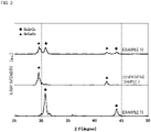
- Fig. 2 illustrates X-ray diffraction patterns of the hydrocarbon reforming catalysts of examples 10 and 15 and comparative example 3.
- a crystal phase attributed to SrZrO 3 and a crystal phase attributed to SrCeO 3 are present in the hydrocarbon reforming catalyst of example 10.
- a crystal phase attributed to SrZrO 3 is present in the hydrocarbon reforming catalyst of example 15, and it can be ascertained that a crystal phase attributed to SrCeO 3 is present in the hydrocarbon reforming catalyst of comparative example 3.
- no diffraction lines attributed to RuO 2 and Ru simple substance are observed regarding these hydrocarbon reforming catalysts.
- Ru is present in at least one structure of a crystal phase containing SrZrO 3 as a primary component and a crystal phase containing SrCeO 3 as a primary component.
- Ru is present in the structure of a crystal phase containing SrZrO 3 as a primary component.
- Ru is present in the structure of a crystal phase containing SrCeO 3 as a primary component.
- Ru is present as a component constituting a complex oxide having a perovskite structure.
- Ru is present as a component constituting a complex oxide having a perovskite structure in the hydrocarbon reforming catalysts of examples 1 to 4, 8, 9, 11, and 15.
- each of Y and Ru is present as a component constituting the complex oxide having a perovskite structure.
- the hydrocarbon reforming catalyst of comparative example 4 was a mixture of SrCO 3 , ZrO 2 , and RuO 2 which were used for preparation since the firing temperature during production was 600°C which was lower than the formation temperature of the complex oxide having a perovskite structure.
- the hydrocarbon reforming catalyst of comparative example 5 was also a mixture of SrCO 3 , ZrO 2 , CeO 2 , and RuO 2 which were used for preparation.
- Each of the hydrocarbon reforming catalysts of examples 1 to 15 and the hydrocarbon reforming catalysts of comparative examples 1 to 5 was finely pulverized by using a mortar, and the resulting powder was subjected to composition analysis by X-ray fluorescence analysis (XRF analysis).
- XRF analysis X-ray fluorescence analysis
- the molar ratio of Ru to Sr was 0.01 or more and 0.38 or less.
- the hydrocarbon reforming catalyst of each of examples 1 to 15 and comparative examples 1 to 5 was pulverized and classified into the size of 0.5 mm to 0.7 mm. Thereafter, a steam reforming evaluation test of a propane gas was performed by using the following method.
- the pipe 1 of the hydrocarbon reforming apparatus 100 illustrated in Fig. 1 was filled with 0.3 g of hydrocarbon reforming catalyst produced by using the above-described method, and heating at 600°C was performed in the heating portion 2. Subsequently, a raw material gas was introduced from the gas feed pipe 4 at a flow rate of nitrogen (N 2 ) of 350 cc/min, propane (C 3 H 8 ) of 7 cc/min, steam (H 2 O) of 60 cc/min, and carbon dioxide (CO 2 ) of 60 cc/min.
- N 2 nitrogen
- propane C 3 H 8
- steam H 2 O
- CO 2 carbon dioxide
- the raw material gas introduced into the pipe 1 was reformed, and a synthetic gas containing hydrogen and carbon monoxide was discharged from the gas discharge pipe 5.
- the synthetic gas discharged from the gas discharge pipe 5 was introduced into a gas analyzer (gas chromatograph) after moisture was removed by a cooling-type trap, and a hydrogen concentration was measured.
- the hydrogen gas concentration percentage in an equilibrium state was 8.1% by volume except for moisture. Therefore, when the reaction of the introduced raw material gas progresses 100%, the concentration of hydrogen in an equilibrium state (hereafter referred to as an equilibrium hydrogen concentration) discharged from the gas discharge pipe 5 is 8.1% by volume.
- the equilibrium achievement percentage of the initial activity was a value higher than 22%, in particular, 29% or more.
- the equilibrium achievement percentage of the initial activity was 22% or less and was a low value.
- the reason for the hydrocarbon reforming catalyst satisfying the requirements of the present invention having high initial activity is as described below. That is, it is conjectured that the hydrocarbon reforming catalyst is stabilized by the Ru component in a solid solution state being dispersed in the complex oxide having at least a crystal phase containing SrZrO 3 as a primary component and having a perovskite structure, aggregation and vaporization of the Ru component under a high-temperature oxidizing condition can be suppressed from occurring, and, as a result, the activity is improved.
- the hydrocarbon reforming catalysts satisfying the requirements of the present invention when the hydrocarbon reforming catalysts of examples 1 to 4 and 8 to 11, in which the complex oxide further had a crystal phase containing SrCeO 3 as a primary component but did not contain Y, were used, the equilibrium achievement percentage of the initial activity was 47% or more and was a high value. Therefore, regarding the hydrocarbon reforming catalyst satisfying the requirements of the present invention, it is favorable that the complex oxide further have a crystal phase containing SrCeO 3 as a primary component but not contain Y.
- the equilibrium achievement percentage of the initial activity was 62% or more and was a high value. Therefore, regarding the hydrocarbon reforming catalyst satisfying the requirements of the present invention, it is favorable that the complex oxide further contain Y but not contain Ce.
- the hydrocarbon reforming catalysts of examples 6 and 7, in which the complex oxide further had a crystal phase containing SrCeO 3 as a primary component and further contained Y at a molar ratio of Y to Ce of 0.6 or less were used, the equilibrium achievement percentage of the initial activity was 72% or more and was a high value. Therefore, regarding the hydrocarbon reforming catalyst satisfying the requirements of the present invention, it is favorable that the complex oxide further have a crystal phase containing SrCeO 3 as a primary component and further contain Y at a molar ratio of Y to Ce of 0.6 or less.
- the hydrocarbon reforming catalysts satisfying the requirements of the present invention when the hydrocarbon reforming catalysts of examples 1 to 14, in which the complex oxide further contained at least one of Ce and Y, were used, the equilibrium achievement percentage of the initial activity after deterioration due to sulfur was 23% or more and was a high value. Therefore, from the viewpoint of recovering the activity after deterioration due to sulfur, regarding the hydrocarbon reforming catalysts satisfying the requirements of the present invention, it is favorable that the complex oxide further contain at least one of Ce and Y.
- the hydrocarbon reforming catalysts of the above-described examples take on granular forms.
- a hydrocarbon reforming catalyst made into a powder may be supported by a ceramic or metal base material and be used.
- a catalyst powder may be formed by a method of press molding, extrusion molding, or the like without using a base material and be used in the form of a pellet, a ring, a honeycomb, or the like.
Landscapes
- Chemical & Material Sciences (AREA)
- Chemical Kinetics & Catalysis (AREA)
- Organic Chemistry (AREA)
- Engineering & Computer Science (AREA)
- Materials Engineering (AREA)
- Inorganic Chemistry (AREA)
- Combustion & Propulsion (AREA)
- General Health & Medical Sciences (AREA)
- Health & Medical Sciences (AREA)
- Physics & Mathematics (AREA)
- Thermal Sciences (AREA)
- Hydrogen, Water And Hydrids (AREA)
- Catalysts (AREA)
Abstract
Description
- The present invention relates to a hydrocarbon reforming catalyst used for forming a synthetic gas containing hydrogen and carbon monoxide from a hydrocarbon-based gas and to a hydrocarbon reforming apparatus including the hydrocarbon reforming catalyst.
- In a known method, a synthetic gas containing hydrogen and carbon monoxide is obtained from a hydrocarbon-based gas by using a catalyst. Examples of the known catalyst used for a reforming reaction of the hydrocarbon-based gas include nickel-based catalysts in which nickel is supported by a base substrate such as alumina, ruthenium-based catalysts in which ruthenium is supported (refer to Patent Document 1), and rhodium-based catalysts in which rhodium is supported by a base substrate such as alumina (refer to Patent Document 2).
- Further, in known catalysts, rhodium, cobalt, or nickel serving as an active component is supported by a carrier including lanthanum aluminate, strontium titanate, or barium titanate, which are perovskite-type compounds, to suppress carbon from depositing and to improve the activity at low temperature (refer to Patent Document 3).
- As a common method for producing a metal-supporting catalyst, an impregnation method in which an active metal is dispersed on the carrier surface by dipping an oxide serving as a carrier into a solution of a metal salt or the like and, thereafter, performing heat treatment is known (Patent Document 1 to Patent Document 3).
- In this regard, the carrier component is required to have high heat stability and strength and, therefore, is sufficiently sintered by being subjected to heat treatment at high temperature, while the dispersibility of the supported metal has to be maintained to obtain high activity. Consequently, to minimize aggregation during a heat treatment step, the supported metal is fixed to the carrier under a heat treatment condition at relatively low temperature by using a production step different from the synthesis of the carrier, as in the impregnation method.
- The catalyst produced by the impregnation method can maintain high metal dispersibility. However, the impregnation step of supporting the metal component is necessary in addition to the carrier component synthesis step. Further, since the metal component is made to adhere by heat treatment at relatively low temperature, coupling between the metal and the carrier is weak, carbon deposition may cause an activity deterioration problem.
- Consequently, as a method for producing a catalyst without using the impregnation step, a method in which a complex oxide containing BaNiY2O5 is synthesized through solid-phase synthesis so as to improve the dispersibility of a Ni component is proposed (Patent Document 4).
-
- Patent Document 1:
Japanese Unexamined Patent Application Publication No. 8-231204 - Patent Document 2:
Japanese Unexamined Patent Application Publication No. 9-168740 - Patent Document 3:
Japanese Unexamined Patent Application Publication No. 2006-346598 - Patent Document 4:
Japanese Unexamined Patent Application Publication No. 2015-136668 - The catalyst described in
Patent Document 4 can suppress carbon from depositing. However, it cannot be said that the activity is sufficiently high, and there is room for improvement. - The present invention addresses the above-described problem, and it is an object to provide a hydrocarbon reforming catalyst having high activity and to provide a hydrocarbon reforming apparatus including such a hydrocarbon reforming catalyst.
- A hydrocarbon reforming catalyst according to the present invention is a catalyst used for forming a synthetic gas containing hydrogen and carbon monoxide from a hydrocarbon-based gas and
- contains a complex oxide having a perovskite structure,
- wherein the complex oxide has a crystal phase containing SrZrO3 as a primary component and contains Ru. Advantageous Effects of Invention
- According to the present invention, a hydrocarbon reforming catalyst having high activity and a hydrocarbon reforming apparatus including such a hydrocarbon reforming catalyst can be provided.
-
- [
Fig. 1] Fig. 1 is a diagram illustrating the outline of the configuration of a hydrocarbon reforming apparatus. - [
Fig. 2] Fig. 2 is a diagram illustrating X-ray diffraction patterns of the hydrocarbon reforming catalysts of examples 10 and 15 and comparative example 3. Description of Embodiments - An embodiment according to the present invention will be illustrated below so as to specifically describe the features of the present invention.
- The hydrocarbon reforming catalyst according to the present invention is a catalyst used for forming a synthetic gas containing hydrogen and carbon monoxide from a hydrocarbon-based gas and satisfies the requirements, that is, containing a complex oxide having a perovskite structure, wherein the complex oxide has a crystal phase containing SrZrO3 as a primary component and contains Ru (hereafter referred to as requirements of the present invention).
- For example, a propane gas containing propane as a primary component or a natural gas containing methane as a primary component may be used as the hydrocarbon-based gas that is a treatment object gas. In addition, hydrocarbon-based gases obtained by vaporizing liquid hydrocarbons, such as gasoline, kerosene, methanol, and ethanol, may also be used.
- The reaction which forms a synthetic gas containing hydrogen and carbon monoxide from a hydrocarbon-based gas will be described with reference to steam reforming of a propane gas as an example. The steam reforming of a propane gas is represented by formula (1) below.
C3H8 + 3H2O → 7H2 + 3CO (1)
- In this regard, the method for forming a synthetic gas containing hydrogen and carbon monoxide from a hydrocarbon-based gas is not limited to steam reforming. For example, oxygen, carbon dioxide, or a mixture thereof may be contained instead of steam. When carbon dioxide is contained, the reforming reaction is represented by formula (2) below.
C3H8 + 3CO2 → 4H2 + 6CO (2)
-
Fig. 1 is a diagram illustrating the outline of the configuration of ahydrocarbon reforming apparatus 100 to form a synthetic gas containing hydrogen and carbon monoxide from a treatment object gas containing at least a hydrocarbon. Thehydrocarbon reforming apparatus 100 includes a pipe 1 through which the treatment object gas passes, aheating portion 2 to heat the treatment object gas passing through the pipe 1, and ahydrocarbon reforming catalyst 3 disposed at a position in contact with the treatment object gas inside the pipe 1. Thehydrocarbon reforming catalyst 3 is a catalyst that satisfies the requirements of the present invention and contains a complex oxide having a perovskite structure, and the complex oxide has a crystal phase containing SrZrO3 as a primary component and containing Ru. In this regard, when just the treatment object gas is at sufficiently high temperature, theheating portion 2 may be skipped. - A
gas feed pipe 4 is coupled to the upstream side of the pipe 1. A hydrocarbon is fed from ahydrocarbon supply source 6 to thegas feed pipe 4. However, thehydrocarbon supply source 6 may be disposed at the former stage of thegas feed pipe 4. In this regard, the hydrocarbon fed from thehydrocarbon supply source 6 may contain other components. - A
gas discharge pipe 5 to discharge a synthetic gas containing hydrogen and carbon monoxide obtained through reforming is coupled to the downstream side of the pipe 1. Thegas discharge pipe 5 is provided with a hydrogen outlet 7 and is configured to be capable of separating hydrogen contained in the synthetic gas. For example, a CO converter may be disposed in thegas discharge pipe 5 so as to remove carbon monoxide contained in the synthetic gas, and hydrogen may be separated through the hydrogen outlet 7. - SrCO3, ZrO2, CeO2, and RuO2 were prepared as the materials for forming the hydrocarbon reforming catalyst and weighed so that the molar ratio of Sr:Zr:Ce:Ru was set to be equal to the ratio described in Table 1, and pebbles, water, and a binder were wet-mixed so as to obtain a mixture. The resulting mixture was dried in an oven at a temperature of 120°C and was pulverized and classified so as to have a granular shape with the size of about 2 mm. Thereafter, hydrocarbon reforming catalysts of examples 1 to 4 were obtained by firing the granular sample in air under the conditions of 1,000°C and 1 hour.
- The hydrocarbon reforming catalysts of examples 1 to 4 were catalysts satisfying the requirements of the present invention. As described in Table 1, the hydrocarbon reforming catalysts of examples 1 to 4 contained Sr, Zr, Ce, and Ru. The molar ratios of Zr to Sr and molar ratios of Ce to Sr of the hydrocarbon reforming catalysts of examples 1 to 4 were equal to each other, but the molar ratios of Ru to Sr differed from each other.
- Regarding the material for forming the hydrocarbon reforming catalyst, SrCO3, ZrO2, CeO2, Y2O3, and RuO2 were prepared and weighed so that the molar ratio of Sr:Zr:Ce:Y:Ru was set to be equal to the ratio described in Table 1, and pebbles, water, and a binder were wet-mixed so as to obtain a mixture. Thereafter, hydrocarbon reforming catalysts of examples 5 to 7 were produced by using the same method as the method for producing the hydrocarbon reforming catalysts of examples 1 to 4.
- The hydrocarbon reforming catalysts of examples 5 to 7 were catalysts satisfying the requirements of the present invention. As described in Table 1, the hydrocarbon reforming catalysts of examples 5 to 7 contained Sr, Zr, Ce, Y, and Ru. The molar ratios of Ru to Sr of the hydrocarbon reforming catalysts of examples 5 to 7 were substantially equal to each other, but the molar ratios of Zr, Ce, and Y differed from each other.
- Regarding the material for forming the hydrocarbon reforming catalyst, SrCO3, ZrO2, CeO2, and RuO2 were prepared and weighed so that the molar ratio of Sr:Zr:Ce:Ru was set to be equal to the ratio described in Table 1, and pebbles, water, and a binder were wet-mixed so as to obtain a mixture. Thereafter, hydrocarbon reforming catalysts of examples 8 to 11 were produced by using the same method as the method for producing the hydrocarbon reforming catalysts of examples 1 to 4.
- The hydrocarbon reforming catalysts of examples 8 to 11 were catalysts satisfying the requirements of the present invention. As described in Table 1, the hydrocarbon reforming catalysts of examples 8 to 11 contained Sr, Zr, Ce, and Ru but did not contain Y in the manner akin to the manner of the hydrocarbon reforming catalysts of examples 1 to 4. The molar ratios of Ru to Sr of the hydrocarbon reforming catalysts of examples 8 to 11 were substantially equal to each other, but the molar ratios of Zr and Ce differed from each other.
- Regarding the material for forming the hydrocarbon reforming catalyst, SrCO3, ZrO2, Y2O3, and RuO2 were prepared and weighed so that the molar ratio of Sr:Zr:Y:Ru was set to be equal to the ratio described in Table 1, and pebbles, water, and a binder were wet-mixed so as to obtain a mixture. Thereafter, hydrocarbon reforming catalysts of examples 12 to 14 were produced by using the same method as the method for producing the hydrocarbon reforming catalysts of examples 1 to 4.
- The hydrocarbon reforming catalysts of examples 12 to 14 were catalysts satisfying the requirements of the present invention. As described in Table 1, the hydrocarbon reforming catalysts of examples 12 to 14 contained Sr, Zr, Y, and Ru but did not contain Ce. The molar ratios of Ru to Sr of the hydrocarbon reforming catalysts of examples 12 to 14 were equal to each other, but the molar ratios of Zr and Y differed from each other.
- Regarding the material for forming the hydrocarbon reforming catalyst, SrCO3, ZrO2, and RuO2 were prepared and weighed so that the molar ratio of Sr:Zr:Ru was set to be equal to the ratio described in Table 1, and pebbles, water, and a binder were wet-mixed so as to obtain a mixture. Thereafter, a hydrocarbon reforming catalyst of example 15 was produced by using the same method as the method for producing the hydrocarbon reforming catalysts of examples 1 to 4.
- The hydrocarbon reforming catalyst of example 15 was a catalyst satisfying the requirements of the present invention. As described in Table 1, the hydrocarbon reforming catalyst of example 15 contained Sr, Zr, and Ru but contained neither Ce nor Y.
- Regarding the material for forming the hydrocarbon reforming catalyst, SrCO3, CeO2, Y2O3, and RuO2 were prepared and weighed so that the molar ratio of Sr:Ce:Y:Ru was set to be equal to the ratio described in Table 1, and pebbles, water, and a binder were wet-mixed so as to obtain a mixture. Thereafter, hydrocarbon reforming catalysts of comparative examples 1 and 2 were produced by using the same method as the method for producing the hydrocarbon reforming catalysts of examples 1 to 4.
- The hydrocarbon reforming catalysts of comparative examples 1 and 2 were catalysts not satisfying the requirements of the present invention. As described in Table 1, the hydrocarbon reforming catalysts of comparative examples 1 and 2 contained Sr, Ce, Y, and Ru but did not contain Zr.
- Regarding the material for forming the hydrocarbon reforming catalyst, SrCO3, CeO2, and RuO2 were prepared and weighed so that the molar ratio of Sr:Ce:Ru was set to be equal to the ratio described in Table 1, and pebbles, water, and a binder were wet-mixed so as to obtain a mixture. Thereafter, a hydrocarbon reforming catalyst of comparative example 3 was produced by using the same method as the method for producing the hydrocarbon reforming catalysts of examples 1 to 4.
- The hydrocarbon reforming catalyst of comparative example 3 was a catalyst not satisfying the requirements of the present invention. As described in Table 1, the hydrocarbon reforming catalyst of comparative example 3 contained Sr, Ce, and Ru but contained neither Zr nor Y.
- Regarding the material for forming the hydrocarbon reforming catalyst, SrCO3, ZrO2, and RuO2 were prepared and weighed so that the molar ratio of Sr:Zr:Ru was set to be equal to the ratio described in Table 1, and pebbles, water, and a binder were wet-mixed so as to obtain a mixture. The molar ratio of Sr:Zr:Ru in the resulting mixture was equal to the molar ratio of the materials used for producing the hydrocarbon reforming catalyst of example 15. Thereafter, a hydrocarbon reforming catalyst of comparative example 4 was produced by using the same method as the method for producing the hydrocarbon reforming catalyst of example 15 except that the firing temperature was set to be 600°C. The hydrocarbon reforming catalyst of comparative example 4 was a catalyst not satisfying the requirements of the present invention.
- Regarding the material for forming the hydrocarbon reforming catalyst, SrCO3, ZrO2, CeO2, and RuO2 were prepared and weighed so that the molar ratio of Sr:Zr:Ce:Ru was set to be equal to the ratio described in Table 1, and pebbles, water, and a binder were wet-mixed so as to obtain a mixture. The molar ratio of Sr:Zr:Ce:Ru in the resulting mixture was equal to the molar ratio of Sr:Zr:Ce:Ru of the materials used for producing the hydrocarbon reforming catalyst of example 10. Thereafter, a hydrocarbon reforming catalyst of comparative example 5 was produced by using the same method as the method for producing the hydrocarbon reforming catalyst of example 10 except that the firing temperature was set to be 600°C. The hydrocarbon reforming catalyst of comparative example 5 was a catalyst not satisfying the requirements of the present invention.
- The hydrocarbon reforming catalysts of examples 1 to 15 and comparative examples 1 to 5 above were pulverized by using a mortar, and the crystal phase was examined by powder XRD measurement. Regarding the powder XRD measurement, Cu-Kα1 was used as the X-ray.
- Table 1 describes the crystal phase and the composition (molar ratio) examined with respect to the hydrocarbon reforming catalysts of examples 1 to 15 and comparative examples 1 to 5.
[Table 1] Catalyst Crystal phase Molar ratio Sr Zr Ce Y Ru Example 1 SrZrO3, SrCeO3 1.00 0.50 0.50 - 0.01 Example 2 SrZrO3, SrCeO3 1.00 0.50 0.50 - 0.04 Example 3 SrZrO3, SrCeO3, SrCO3 1.00 0.50 0.50 - 0.19 Example 4 SrZrO3, SrCeO3, SrCO3 1.00 0.50 0.50 - 0.38 Example 5 SrZrO3, SrCeO3, Y2O3, SrCO3 1.00 0.40 0.30 0.30 0.07 Example 6 SrZrO3, SrCeO3 1.00 0.40 0.50 0.10 0.08 Example 7 SrZrO3, SrCeO3, Y2O3, SrCO3 1.00 0.20 0.50 0.30 0.07 Example 8 SrZrO3, SrCeO3 1.00 0.90 0.10 - 0.07 Example 9 SrZrO3, SrCeO3, SrCO3 1.00 0.70 0.30 - 0.07 Example 10 SrZrO3, SrCeO3, SrCO3 1.00 0.50 0.50 - 0.08 Example 11 SrZrO3, SrCeO3 1.00 0.20 0.80 - 0.08 Example 12 SrZrO3 1.00 0.90 - 0.10 0.07 Example 13 SrZrO3, SrCeO3 1.00 0.70 - 0.30 0.07 Example 14 SrZrO3, Y2O3, SrCO3 1.00 0.50 - 0.50 0.07 Example 15 SrZrO3 1.00 1.00 - - 0.07 Comparative example 1 SrCeO3 1.00 - 0.80 0.20 0.08 Comparative example 2 SrCeO3, Y2O3, SrCO3 1.00 - 0.50 0.50 0.07 Comparative example 3 SrCeO3 1.00 - 1.00 - 0.08 Comparative example 4 SrCO3, ZrO2, RuO2 1.00 1.00 - - 0.07 Comparative example 5 SrCO3, ZrO2, CeO2 RuO2 1.00 0.50 0.50 - 0.08 - Regarding the hydrocarbon reforming catalysts of examples 1 to 15, it was ascertained that a crystal phase of a complex oxide having a perovskite structure, specifically, at least a crystal phase containing SrZrO3 as a primary component was present. Further specifically, regarding the hydrocarbon reforming catalysts of examples 1 to 11, it was ascertained that a crystal phase containing SrZrO3 as a primary component and a crystal phase containing SrCeO3 as a primary component were present. In addition, regarding the hydrocarbon reforming catalysts of examples 12 to 15, it was ascertained that a crystal phase containing SrZrO3 as a primary component was present.
- Regarding hydrocarbon reforming catalysts of some examples, heterogeneous phases such as SrCO3 and Y2O3 were also observed in accordance with the composition ratio. However, even in these hydrocarbon reforming catalysts, the main crystal phase of the complex oxide having a perovskite structure was a crystal phase containing SrZrO3 as a primary component when a crystal phase containing SrCeO3 as a primary component was not contained and was a crystal phase containing SrZrO3 as a primary component and a crystal phase containing SrCeO3 as a primary component when a crystal phase containing SrCeO3 as a primary component was contained.
-
Fig. 2 illustrates X-ray diffraction patterns of the hydrocarbon reforming catalysts of examples 10 and 15 and comparative example 3. As illustrated inFig. 2 , it can be ascertained that a crystal phase attributed to SrZrO3 and a crystal phase attributed to SrCeO3 are present in the hydrocarbon reforming catalyst of example 10. In addition, it can be ascertained that a crystal phase attributed to SrZrO3 is present in the hydrocarbon reforming catalyst of example 15, and it can be ascertained that a crystal phase attributed to SrCeO3 is present in the hydrocarbon reforming catalyst of comparative example 3. On the other hand, no diffraction lines attributed to RuO2 and Ru simple substance are observed regarding these hydrocarbon reforming catalysts. - That is, in the hydrocarbon reforming catalyst of example 10, Ru is present in at least one structure of a crystal phase containing SrZrO3 as a primary component and a crystal phase containing SrCeO3 as a primary component. In addition, in the hydrocarbon reforming catalyst of example 15, Ru is present in the structure of a crystal phase containing SrZrO3 as a primary component. Further, in the hydrocarbon reforming catalyst of comparative example 3, Ru is present in the structure of a crystal phase containing SrCeO3 as a primary component. In other words, Ru is present as a component constituting a complex oxide having a perovskite structure.
- Likewise, Ru is present as a component constituting a complex oxide having a perovskite structure in the hydrocarbon reforming catalysts of examples 1 to 4, 8, 9, 11, and 15. Regarding the hydrocarbon reforming catalysts of examples 5 to 7 and 12 to 14 in which Y and Ru are contained in a complex oxide, each of Y and Ru is present as a component constituting the complex oxide having a perovskite structure.
- On the other hand, it was ascertained that the hydrocarbon reforming catalyst of comparative example 4 was a mixture of SrCO3, ZrO2, and RuO2 which were used for preparation since the firing temperature during production was 600°C which was lower than the formation temperature of the complex oxide having a perovskite structure. Likewise, it was ascertained that the hydrocarbon reforming catalyst of comparative example 5 was also a mixture of SrCO3, ZrO2, CeO2, and RuO2 which were used for preparation.
- Each of the hydrocarbon reforming catalysts of examples 1 to 15 and the hydrocarbon reforming catalysts of comparative examples 1 to 5 was finely pulverized by using a mortar, and the resulting powder was subjected to composition analysis by X-ray fluorescence analysis (XRF analysis). As a result, it was ascertained that regarding all the hydrocarbon reforming catalysts subjected to the composition analysis, the element molar ratio of the formulation for weighing was maintained and a change in the element molar ratio, such as reduction in each component due to heating and firing treatment, did not occur.
- In this regard, in the hydrocarbon reforming catalysts of examples 1 to 15, the molar ratio of Ru to Sr was 0.01 or more and 0.38 or less.
- The hydrocarbon reforming catalyst of each of examples 1 to 15 and comparative examples 1 to 5 was pulverized and classified into the size of 0.5 mm to 0.7 mm. Thereafter, a steam reforming evaluation test of a propane gas was performed by using the following method.
- The pipe 1 of the
hydrocarbon reforming apparatus 100 illustrated inFig. 1 was filled with 0.3 g of hydrocarbon reforming catalyst produced by using the above-described method, and heating at 600°C was performed in theheating portion 2. Subsequently, a raw material gas was introduced from thegas feed pipe 4 at a flow rate of nitrogen (N2) of 350 cc/min, propane (C3H8) of 7 cc/min, steam (H2O) of 60 cc/min, and carbon dioxide (CO2) of 60 cc/min. - The raw material gas introduced into the pipe 1 was reformed, and a synthetic gas containing hydrogen and carbon monoxide was discharged from the
gas discharge pipe 5. The synthetic gas discharged from thegas discharge pipe 5 was introduced into a gas analyzer (gas chromatograph) after moisture was removed by a cooling-type trap, and a hydrogen concentration was measured. - Herein, as a result of calculation of the equilibrium gas composition at the above-described conditions of the gas partial pressure and the temperature, the hydrogen gas concentration percentage in an equilibrium state was 8.1% by volume except for moisture. Therefore, when the reaction of the introduced raw material gas progresses 100%, the concentration of hydrogen in an equilibrium state (hereafter referred to as an equilibrium hydrogen concentration) discharged from the
gas discharge pipe 5 is 8.1% by volume. - It was assumed that no sulfur component was present for the first 1 hour from introduction of the raw material gas, and the hydrogen concentration after 1 hour (initial hydrogen concentration) was measured so as to examine the initial activity of the hydrocarbon reforming catalyst. Table 2 describes the concentration of hydrogen discharged from the gas discharge pipe 5 (initial hydrogen concentration) and the equilibrium achievement percentage of the initial activity when the hydrocarbon reforming catalyst of each of the examples and the comparative examples was used. The equilibrium achievement percentage of the initial activity was defined by formula (3) below.

- After the above-described initial activity was examined, a SO2 gas was mixed so that the proportion was set to be 10 ppm relative to the total flow rate of the raw material gas of 477 cc/min, the hydrogen gas concentration after 1 hour was measured so as to examine deterioration in the catalyst activity in the presence of sulfur. Table 2 describes the concentration of hydrogen discharged from the
gas discharge pipe 5 after 1 hour in the presence of sulfur and the equilibrium achievement percentage when the hydrocarbon reforming catalyst of each of the examples and the comparative examples was used. In Table 2, these are expressed as the hydrogen concentration "After deterioration due to sulfur" and "Equilibrium achievement percentage after deterioration due to sulfur". The equilibrium achievement percentage after deterioration due to sulfur was defined by formula (4) below.
- After the test was completed, to examine presence or absence of carbon deposition, the hydrocarbon reforming catalyst was cooled and removed in a N2 atmosphere, and a change in the weight of the catalyst due to carbon combustion was examined by TG-DTA (thermogravimetric-differential thermal analysis). As a result, regarding all the hydrocarbon reforming catalysts of the examples and comparative examples subjected to the evaluation, carbon deposition was not observed.
[Table 2] Catalyst Hydrogen concentration (% by volume) Equilibrium achievement percentage of initial activity Equilibrium achievement percentage after deterioration due to sulfur Initial stage After deterioration due to sulfur Example 1 3.8 2.8 47% 35% Example 2 5.8 4.2 72% 52% Example 3 8.1 8.1 100% 100% Example 4 8.1 8.1 100% 100% Example 5 2.3 1.8 29% 23% Example 6 5.9 3.8 72% 47% Example 7 7.6 5.5 94% 68% Example 8 7.2 4.4 89% 54% Example 9 7.8 5.9 97% 72% Example 10 8.1 7.1 100% 87% Example 11 8.0 2.7 98% 34% Example 12 7.5 4.2 93% 52% Example 13 6.7 6.1 83% 75% Example 14 5.0 3.0 62% 37% Example 15 7.3 1.3 90% 16% Comparative example 1 0.0 0.0 0% 0% Comparative example 2 0.5 0.1 6% 1% Comparative example 3 0.4 0.1 5% 1% Comparative example 4 1.8 0.0 22% 0% Comparative example 5 1.2 0.0 15% 0% - As described in Table 2, when the hydrocarbon reforming catalysts of examples 1 to 15 satisfying the requirements of the present invention were used, the equilibrium achievement percentage of the initial activity was a value higher than 22%, in particular, 29% or more. On the other hand, when the hydrocarbon reforming catalysts of comparative examples 1 to 5 not satisfying the requirements of the present invention were used, the equilibrium achievement percentage of the initial activity was 22% or less and was a low value.
- The reason for the hydrocarbon reforming catalyst satisfying the requirements of the present invention having high initial activity is as described below. That is, it is conjectured that the hydrocarbon reforming catalyst is stabilized by the Ru component in a solid solution state being dispersed in the complex oxide having at least a crystal phase containing SrZrO3 as a primary component and having a perovskite structure, aggregation and vaporization of the Ru component under a high-temperature oxidizing condition can be suppressed from occurring, and, as a result, the activity is improved.
- In this regard, of the hydrocarbon reforming catalysts satisfying the requirements of the present invention, when the hydrocarbon reforming catalysts of examples 1 to 4 and 8 to 11, in which the complex oxide further had a crystal phase containing SrCeO3 as a primary component but did not contain Y, were used, the equilibrium achievement percentage of the initial activity was 47% or more and was a high value. Therefore, regarding the hydrocarbon reforming catalyst satisfying the requirements of the present invention, it is favorable that the complex oxide further have a crystal phase containing SrCeO3 as a primary component but not contain Y.
- In addition, when the hydrocarbon reforming catalysts of examples 12 to 14, in which the complex oxide further contained Y but did not contain Ce, were used, the equilibrium achievement percentage of the initial activity was 62% or more and was a high value. Therefore, regarding the hydrocarbon reforming catalyst satisfying the requirements of the present invention, it is favorable that the complex oxide further contain Y but not contain Ce.
- In addition, when the hydrocarbon reforming catalysts of examples 6 and 7, in which the complex oxide further had a crystal phase containing SrCeO3 as a primary component and further contained Y at a molar ratio of Y to Ce of 0.6 or less, were used, the equilibrium achievement percentage of the initial activity was 72% or more and was a high value. Therefore, regarding the hydrocarbon reforming catalyst satisfying the requirements of the present invention, it is favorable that the complex oxide further have a crystal phase containing SrCeO3 as a primary component and further contain Y at a molar ratio of Y to Ce of 0.6 or less.
- As described in Table 2, when the hydrocarbon reforming catalysts of comparative examples 1 to 5 not satisfying the requirements of the present invention were used, the equilibrium achievement percentage after deterioration due to sulfur was 1% or less. On the other hand, when the hydrocarbon reforming catalysts of examples 1 to 15 satisfying the requirements of the present invention were used, the equilibrium achievement percentage of the initial activity after deterioration due to sulfur was 16% or more. It is conjectured that regarding the hydrocarbon reforming catalysts satisfying the requirements of the present invention, since Ru component in a solid solution state is dispersed in the complex oxide, the bonding force is strong, an effect of suppressing a poisoning component such as sulfur from adsorbing or forming a compound is obtained, and high sulfur resistance is provided.
- In this regard, of the hydrocarbon reforming catalysts satisfying the requirements of the present invention, when the hydrocarbon reforming catalysts of examples 1 to 14, in which the complex oxide further contained at least one of Ce and Y, were used, the equilibrium achievement percentage of the initial activity after deterioration due to sulfur was 23% or more and was a high value. Therefore, from the viewpoint of recovering the activity after deterioration due to sulfur, regarding the hydrocarbon reforming catalysts satisfying the requirements of the present invention, it is favorable that the complex oxide further contain at least one of Ce and Y.
- The present invention is not limited to the above-described embodiment and can be variously applied and modified within the scope of the present invention.
- For example, the hydrocarbon reforming catalysts of the above-described examples take on granular forms. However, similarly to the common metal-supporting catalyst, a hydrocarbon reforming catalyst made into a powder may be supported by a ceramic or metal base material and be used. Alternatively, a catalyst powder may be formed by a method of press molding, extrusion molding, or the like without using a base material and be used in the form of a pellet, a ring, a honeycomb, or the like.
-
- 1
- pipe
- 2
- heating portion
- 3
- hydrocarbon reforming catalyst
- 4
- gas feed pipe
- 5
- gas discharge pipe
- 6
- hydrocarbon supply source
- 7
- hydrogen outlet
- 100
- hydrocarbon reforming apparatus
Claims (9)
- A hydrocarbon reforming catalyst used for forming a synthetic gas containing hydrogen and carbon monoxide from a hydrocarbon-based gas, the hydrocarbon reforming catalyst comprising:a complex oxide having a perovskite structure,wherein the complex oxide has a crystal phase containing SrZrO3 as a primary component and contains Ru.
- The hydrocarbon reforming catalyst according to Claim 1, wherein the molar ratio of Ru to Sr is 0.01 or more and 0.38 or less.
- The hydrocarbon reforming catalyst according to Claim 1 or Claim 2, wherein the complex oxide further has a crystal phase containing SrCeO3 as a primary component.
- The hydrocarbon reforming catalyst according to Claim 3, wherein the complex oxide further contains Y.
- The hydrocarbon reforming catalyst according to Claim 4, wherein the molar ratio of Y to Ce is 0.6 or less.
- The hydrocarbon reforming catalyst according to Claim 3, wherein the complex oxide does not contain Y.
- The hydrocarbon reforming catalyst according to Claim 1 or Claim 2, wherein the complex oxide further contains Y but does not contain Ce.
- The hydrocarbon reforming catalyst according to Claim 1 or Claim 2, wherein the complex oxide further contains at least one of Ce and Y.
- A hydrocarbon reforming apparatus comprising:a pipe through which a treatment object gas containing at least a hydrocarbon passes; andthe hydrocarbon reforming catalyst according to any one of Claims 1 to 8 disposed at a position in contact with the treatment object gas inside the pipe.
Applications Claiming Priority (2)
| Application Number | Priority Date | Filing Date | Title |
|---|---|---|---|
| JP2020000916 | 2020-01-07 | ||
| PCT/JP2020/041152 WO2021140733A1 (en) | 2020-01-07 | 2020-11-04 | Hydrocarbon reforming catalyst and hydrocarbon reforming device |
Publications (2)
| Publication Number | Publication Date |
|---|---|
| EP4070885A1 true EP4070885A1 (en) | 2022-10-12 |
| EP4070885A4 EP4070885A4 (en) | 2024-01-03 |
Family
ID=76787838
Family Applications (1)
| Application Number | Title | Priority Date | Filing Date |
|---|---|---|---|
| EP20912112.8A Pending EP4070885A4 (en) | 2020-01-07 | 2020-11-04 | Hydrocarbon reforming catalyst and hydrocarbon reforming device |
Country Status (5)
| Country | Link |
|---|---|
| US (1) | US12589381B2 (en) |
| EP (1) | EP4070885A4 (en) |
| JP (1) | JP7184214B2 (en) |
| CN (1) | CN114829003A (en) |
| WO (1) | WO2021140733A1 (en) |
Families Citing this family (1)
| Publication number | Priority date | Publication date | Assignee | Title |
|---|---|---|---|---|
| CN114829003A (en) * | 2020-01-07 | 2022-07-29 | 株式会社村田制作所 | Hydrocarbon reforming catalyst and hydrocarbon reforming apparatus |
Family Cites Families (22)
| Publication number | Priority date | Publication date | Assignee | Title |
|---|---|---|---|---|
| JPS63302950A (en) | 1987-06-03 | 1988-12-09 | Nissan Motor Co Ltd | Waste gas purifying catalyst |
| JP2618319B2 (en) | 1992-12-14 | 1997-06-11 | 財団法人石油産業活性化センター | Catalyst structure for catalytic reduction of nitrogen oxides |
| JPH0780310A (en) * | 1993-06-29 | 1995-03-28 | Idemitsu Kosan Co Ltd | Process for producing perovskite-type or perovskite-like oxide-supported catalyst |
| JPH08231204A (en) | 1994-12-27 | 1996-09-10 | Sekiyu Sangyo Kasseika Center | Method for producing hydrogen and carbon monoxide by carbon dioxide reforming reaction |
| JP3638358B2 (en) | 1995-12-20 | 2005-04-13 | 財団法人石油産業活性化センター | Carbon dioxide reforming catalyst and reforming method using the same |
| AU759921B2 (en) * | 1998-09-21 | 2003-05-01 | University Of Queensland, The | Catalysts and process for reforming of hydrocarbons |
| JP2002346341A (en) | 2001-05-23 | 2002-12-03 | Isuzu Motors Ltd | Exhaust gas purification device |
| WO2003033431A1 (en) | 2001-10-15 | 2003-04-24 | Nippon Steel Corporation | Porcelain composition, composite material comprising catalyst and ceramic, film reactor, method for producing synthetic gas, apparatus for producing synthetic gas and method for activating catalyst |
| JP4430291B2 (en) * | 2001-10-15 | 2010-03-10 | 国際石油開発帝石株式会社 | Syngas production method |
| CN1674985A (en) * | 2002-07-09 | 2005-09-28 | 大发工业株式会社 | Catalyst for Exhaust Purification |
| AU2003303385A1 (en) * | 2002-12-20 | 2004-07-22 | Honda Giken Kogyo Kabushiki Kaisha | Platinum-ruthenium containing catalyst formulations for hydrogen generation |
| WO2004074205A1 (en) * | 2003-02-24 | 2004-09-02 | National University Corporation Nagoya University | Proton-conductive and electron-conductive ceramic |
| JP2006346598A (en) | 2005-06-16 | 2006-12-28 | Nissan Motor Co Ltd | Steam reforming catalyst |
| WO2008084785A1 (en) * | 2007-01-09 | 2008-07-17 | Murata Manufacturing Co., Ltd. | Carbon dioxide reforming catalyst and method for production thereof |
| CN101224427A (en) * | 2008-02-01 | 2008-07-23 | 汉能科技有限公司 | Catalyst for hydrogen production from methane vapor reforming and preparing method thereof |
| US8133463B1 (en) * | 2008-04-14 | 2012-03-13 | The United States Of America As Represented By The Department Of Energy | Pyrochlore-type catalysts for the reforming of hydrocarbon fuels |
| JP5126560B2 (en) * | 2009-09-02 | 2013-01-23 | 株式会社村田製作所 | Hydrocarbon gas reforming catalyst, method for producing the same, and method for producing synthesis gas |
| US20160107143A1 (en) * | 2013-03-15 | 2016-04-21 | Siluria Technologies, Inc. | Catalysts for petrochemical catalysis |
| JP5780271B2 (en) * | 2013-07-22 | 2015-09-16 | 新日鐵住金株式会社 | Catalyst for reforming tar-containing gas, method for producing the same, and method for reforming tar-containing gas |
| JP6187282B2 (en) | 2014-01-23 | 2017-08-30 | 株式会社村田製作所 | Hydrocarbon reforming catalyst |
| CN108695532B (en) * | 2017-04-11 | 2021-01-15 | 阜阳师范学院 | High-stability doped strontium cerate/zirconium cerate-alkali metal salt composite electrolyte and preparation method thereof |
| CN114829003A (en) * | 2020-01-07 | 2022-07-29 | 株式会社村田制作所 | Hydrocarbon reforming catalyst and hydrocarbon reforming apparatus |
-
2020
- 2020-11-04 CN CN202080088742.8A patent/CN114829003A/en active Pending
- 2020-11-04 JP JP2021569738A patent/JP7184214B2/en active Active
- 2020-11-04 EP EP20912112.8A patent/EP4070885A4/en active Pending
- 2020-11-04 WO PCT/JP2020/041152 patent/WO2021140733A1/en not_active Ceased
-
2022
- 2022-06-27 US US17/849,912 patent/US12589381B2/en active Active
Also Published As
| Publication number | Publication date |
|---|---|
| WO2021140733A1 (en) | 2021-07-15 |
| EP4070885A4 (en) | 2024-01-03 |
| US20220331779A1 (en) | 2022-10-20 |
| US12589381B2 (en) | 2026-03-31 |
| JP7184214B2 (en) | 2022-12-06 |
| JPWO2021140733A1 (en) | 2021-07-15 |
| CN114829003A (en) | 2022-07-29 |
Similar Documents
| Publication | Publication Date | Title |
|---|---|---|
| EP3804850B1 (en) | Hydrocarbon reforming catalyst and hydrocarbon reforming apparatus | |
| US8329612B2 (en) | Catalyst for reforming hydrocarbon gas, method of manufacturing the same, and method of manufacturing synthesized gas | |
| EP2474355A1 (en) | Hydrocarbon gas reforming catalyst, method for producing same, and method for producing synthetic gas | |
| WO2010001690A1 (en) | Carbon dioxide reforming process | |
| US20050232857A1 (en) | Catalyst for hydrogen generation through steam reforming of hydrocarbons | |
| US20110084237A1 (en) | Proton conducting membranes for hydrogen production and separation | |
| Brackmann et al. | LaCoO3 perovskite on ceramic monoliths–pre and post reaction analyzes of the partial oxidation of methane | |
| EP4245409A1 (en) | Methane-reforming catalyst and method for producing same | |
| US20090108238A1 (en) | Catalyst for reforming hydrocarbons | |
| CN110013840A (en) | Steam reforming catalyst | |
| US12589381B2 (en) | Hydrocarbon reforming catalyst and hydrocarbon reforming apparatus | |
| US12390792B2 (en) | Hydrocarbon reforming catalyst and hydrocarbon reforming device | |
| EP3988206B1 (en) | Hydrocarbon reforming catalyst and hydrocarbon reforming device | |
| EP4056268A1 (en) | Hydrocarbon reforming catalyst, hydrocarbon reforming device, and method for regenerating hydrocarbon reforming catalyst poisoned by sulfur | |
| JP2006116372A (en) | Carbon monoxide selective oxidation catalyst | |
| JP5626446B2 (en) | Hydrocarbon carbon dioxide reforming catalyst and hydrocarbon carbon dioxide reforming method | |
| JP2006116370A (en) | Carbon monoxide shift reaction catalyst |
Legal Events
| Date | Code | Title | Description |
|---|---|---|---|
| STAA | Information on the status of an ep patent application or granted ep patent |
Free format text: STATUS: THE INTERNATIONAL PUBLICATION HAS BEEN MADE |
|
| PUAI | Public reference made under article 153(3) epc to a published international application that has entered the european phase |
Free format text: ORIGINAL CODE: 0009012 |
|
| STAA | Information on the status of an ep patent application or granted ep patent |
Free format text: STATUS: REQUEST FOR EXAMINATION WAS MADE |
|
| 17P | Request for examination filed |
Effective date: 20220704 |
|
| AK | Designated contracting states |
Kind code of ref document: A1 Designated state(s): AL AT BE BG CH CY CZ DE DK EE ES FI FR GB GR HR HU IE IS IT LI LT LU LV MC MK MT NL NO PL PT RO RS SE SI SK SM TR |
|
| DAV | Request for validation of the european patent (deleted) | ||
| DAX | Request for extension of the european patent (deleted) | ||
| A4 | Supplementary search report drawn up and despatched |
Effective date: 20231204 |
|
| RIC1 | Information provided on ipc code assigned before grant |
Ipc: C01B 3/40 20060101ALI20231128BHEP Ipc: B01J 37/08 20060101ALI20231128BHEP Ipc: B01J 37/00 20060101ALI20231128BHEP Ipc: B01J 35/02 20060101ALI20231128BHEP Ipc: B01J 23/00 20060101ALI20231128BHEP Ipc: B01J 27/232 20060101ALI20231128BHEP Ipc: B01J 23/58 20060101ALI20231128BHEP Ipc: B01J 23/63 20060101AFI20231128BHEP |