EP4070879A1 - Molten salt-ceramic composite membrane with high co2 permeability - Google Patents
Molten salt-ceramic composite membrane with high co2 permeability Download PDFInfo
- Publication number
- EP4070879A1 EP4070879A1 EP21382302.4A EP21382302A EP4070879A1 EP 4070879 A1 EP4070879 A1 EP 4070879A1 EP 21382302 A EP21382302 A EP 21382302A EP 4070879 A1 EP4070879 A1 EP 4070879A1
- Authority
- EP
- European Patent Office
- Prior art keywords
- mgo
- mixture
- temperature
- ceramic
- oxide
- Prior art date
- Legal status (The legal status is an assumption and is not a legal conclusion. Google has not performed a legal analysis and makes no representation as to the accuracy of the status listed.)
- Withdrawn
Links
- 239000012528 membrane Substances 0.000 title claims abstract description 56
- 239000000919 ceramic Substances 0.000 title claims abstract description 45
- 239000002131 composite material Substances 0.000 title claims abstract description 32
- 230000035699 permeability Effects 0.000 title description 20
- 239000000203 mixture Substances 0.000 claims abstract description 49
- 230000005496 eutectics Effects 0.000 claims abstract description 41
- 239000011148 porous material Substances 0.000 claims abstract description 38
- 238000000034 method Methods 0.000 claims abstract description 30
- 239000011159 matrix material Substances 0.000 claims abstract description 18
- 150000004649 carbonic acid derivatives Chemical class 0.000 claims abstract description 17
- 238000005530 etching Methods 0.000 claims abstract description 12
- 230000008569 process Effects 0.000 claims abstract description 11
- 239000000395 magnesium oxide Substances 0.000 claims description 59
- CPLXHLVBOLITMK-UHFFFAOYSA-N magnesium oxide Inorganic materials [Mg]=O CPLXHLVBOLITMK-UHFFFAOYSA-N 0.000 claims description 59
- AXZKOIWUVFPNLO-UHFFFAOYSA-N magnesium;oxygen(2-) Chemical compound [O-2].[Mg+2] AXZKOIWUVFPNLO-UHFFFAOYSA-N 0.000 claims description 44
- 238000002844 melting Methods 0.000 claims description 25
- 230000008018 melting Effects 0.000 claims description 25
- 229910001233 yttria-stabilized zirconia Inorganic materials 0.000 claims description 21
- RVTZCBVAJQQJTK-UHFFFAOYSA-N oxygen(2-);zirconium(4+) Chemical compound [O-2].[O-2].[Zr+4] RVTZCBVAJQQJTK-UHFFFAOYSA-N 0.000 claims description 17
- 229910001928 zirconium oxide Inorganic materials 0.000 claims description 17
- 239000007789 gas Substances 0.000 claims description 16
- 238000007711 solidification Methods 0.000 claims description 16
- 239000000463 material Substances 0.000 claims description 15
- 230000008023 solidification Effects 0.000 claims description 15
- BVKZGUZCCUSVTD-UHFFFAOYSA-L Carbonate Chemical compound [O-]C([O-])=O BVKZGUZCCUSVTD-UHFFFAOYSA-L 0.000 claims description 13
- 239000011777 magnesium Substances 0.000 claims description 12
- 229910052809 inorganic oxide Inorganic materials 0.000 claims description 11
- 229910000288 alkali metal carbonate Inorganic materials 0.000 claims description 7
- 150000008041 alkali metal carbonates Chemical class 0.000 claims description 7
- 239000000843 powder Substances 0.000 claims description 7
- QTBSBXVTEAMEQO-UHFFFAOYSA-N Acetic acid Chemical compound CC(O)=O QTBSBXVTEAMEQO-UHFFFAOYSA-N 0.000 claims description 6
- CDBYLPFSWZWCQE-UHFFFAOYSA-L Sodium Carbonate Chemical compound [Na+].[Na+].[O-]C([O-])=O CDBYLPFSWZWCQE-UHFFFAOYSA-L 0.000 claims description 6
- XLYOFNOQVPJJNP-UHFFFAOYSA-N water Chemical compound O XLYOFNOQVPJJNP-UHFFFAOYSA-N 0.000 claims description 6
- 239000002253 acid Substances 0.000 claims description 5
- 238000001816 cooling Methods 0.000 claims description 5
- 230000004580 weight loss Effects 0.000 claims description 5
- 239000004568 cement Substances 0.000 claims description 4
- CETPSERCERDGAM-UHFFFAOYSA-N ceric oxide Chemical compound O=[Ce]=O CETPSERCERDGAM-UHFFFAOYSA-N 0.000 claims description 4
- 229910000422 cerium(IV) oxide Inorganic materials 0.000 claims description 4
- 239000012153 distilled water Substances 0.000 claims description 4
- BWHMMNNQKKPAPP-UHFFFAOYSA-L potassium carbonate Chemical compound [K+].[K+].[O-]C([O-])=O BWHMMNNQKKPAPP-UHFFFAOYSA-L 0.000 claims description 4
- 238000010438 heat treatment Methods 0.000 claims description 3
- 238000001566 impedance spectroscopy Methods 0.000 claims description 3
- XGZVUEUWXADBQD-UHFFFAOYSA-L lithium carbonate Chemical compound [Li+].[Li+].[O-]C([O-])=O XGZVUEUWXADBQD-UHFFFAOYSA-L 0.000 claims description 3
- 229910052808 lithium carbonate Inorganic materials 0.000 claims description 3
- 229910000027 potassium carbonate Inorganic materials 0.000 claims description 3
- 238000005245 sintering Methods 0.000 claims description 3
- 229910000029 sodium carbonate Inorganic materials 0.000 claims description 3
- 238000003325 tomography Methods 0.000 claims description 3
- RUDFQVOCFDJEEF-UHFFFAOYSA-N yttrium(III) oxide Inorganic materials [O-2].[O-2].[O-2].[Y+3].[Y+3] RUDFQVOCFDJEEF-UHFFFAOYSA-N 0.000 claims description 3
- XMIIGOLPHOKFCH-UHFFFAOYSA-N 3-phenylpropionic acid Chemical compound OC(=O)CCC1=CC=CC=C1 XMIIGOLPHOKFCH-UHFFFAOYSA-N 0.000 claims description 2
- UGFAIRIUMAVXCW-UHFFFAOYSA-N Carbon monoxide Chemical compound [O+]#[C-] UGFAIRIUMAVXCW-UHFFFAOYSA-N 0.000 claims description 2
- GRYLNZFGIOXLOG-UHFFFAOYSA-N Nitric acid Chemical compound O[N+]([O-])=O GRYLNZFGIOXLOG-UHFFFAOYSA-N 0.000 claims description 2
- QAOWNCQODCNURD-UHFFFAOYSA-N Sulfuric acid Chemical compound OS(O)(=O)=O QAOWNCQODCNURD-UHFFFAOYSA-N 0.000 claims description 2
- 229910000421 cerium(III) oxide Inorganic materials 0.000 claims description 2
- 238000000151 deposition Methods 0.000 claims description 2
- 239000003546 flue gas Substances 0.000 claims description 2
- CMIHHWBVHJVIGI-UHFFFAOYSA-N gadolinium(III) oxide Inorganic materials [O-2].[O-2].[O-2].[Gd+3].[Gd+3] CMIHHWBVHJVIGI-UHFFFAOYSA-N 0.000 claims description 2
- CJNBYAVZURUTKZ-UHFFFAOYSA-N hafnium(IV) oxide Inorganic materials O=[Hf]=O CJNBYAVZURUTKZ-UHFFFAOYSA-N 0.000 claims description 2
- 238000002156 mixing Methods 0.000 claims description 2
- 229910017604 nitric acid Inorganic materials 0.000 claims description 2
- FKTOIHSPIPYAPE-UHFFFAOYSA-N samarium(III) oxide Inorganic materials [O-2].[O-2].[O-2].[Sm+3].[Sm+3] FKTOIHSPIPYAPE-UHFFFAOYSA-N 0.000 claims description 2
- 238000004626 scanning electron microscopy Methods 0.000 claims description 2
- 238000001764 infiltration Methods 0.000 abstract description 5
- 230000008595 infiltration Effects 0.000 abstract description 5
- 238000000926 separation method Methods 0.000 abstract description 2
- 239000012071 phase Substances 0.000 description 13
- 239000000047 product Substances 0.000 description 7
- 239000007788 liquid Substances 0.000 description 6
- 239000007787 solid Substances 0.000 description 6
- 239000012466 permeate Substances 0.000 description 5
- 238000010587 phase diagram Methods 0.000 description 5
- 150000003839 salts Chemical class 0.000 description 5
- MCMNRKCIXSYSNV-UHFFFAOYSA-N Zirconium dioxide Chemical compound O=[Zr]=O MCMNRKCIXSYSNV-UHFFFAOYSA-N 0.000 description 4
- -1 carbonate anions Chemical class 0.000 description 3
- 238000004090 dissolution Methods 0.000 description 3
- 238000000635 electron micrograph Methods 0.000 description 3
- 238000002474 experimental method Methods 0.000 description 3
- 239000007790 solid phase Substances 0.000 description 3
- 239000000243 solution Substances 0.000 description 3
- 230000008901 benefit Effects 0.000 description 2
- 238000006243 chemical reaction Methods 0.000 description 2
- 150000001875 compounds Chemical class 0.000 description 2
- 239000013078 crystal Substances 0.000 description 2
- 238000005516 engineering process Methods 0.000 description 2
- 238000007654 immersion Methods 0.000 description 2
- 229910052744 lithium Inorganic materials 0.000 description 2
- 238000004519 manufacturing process Methods 0.000 description 2
- 229910052700 potassium Inorganic materials 0.000 description 2
- 239000000376 reactant Substances 0.000 description 2
- 229910052708 sodium Inorganic materials 0.000 description 2
- QBYHSJRFOXINMH-UHFFFAOYSA-N [Co].[Sr].[La] Chemical compound [Co].[Sr].[La] QBYHSJRFOXINMH-UHFFFAOYSA-N 0.000 description 1
- 238000010306 acid treatment Methods 0.000 description 1
- 239000000654 additive Substances 0.000 description 1
- 239000003513 alkali Substances 0.000 description 1
- 230000008859 change Effects 0.000 description 1
- 230000000052 comparative effect Effects 0.000 description 1
- 239000000470 constituent Substances 0.000 description 1
- 238000005520 cutting process Methods 0.000 description 1
- 230000007423 decrease Effects 0.000 description 1
- 230000003247 decreasing effect Effects 0.000 description 1
- 238000010586 diagram Methods 0.000 description 1
- 238000009826 distribution Methods 0.000 description 1
- 230000009977 dual effect Effects 0.000 description 1
- 230000000694 effects Effects 0.000 description 1
- 239000003792 electrolyte Substances 0.000 description 1
- 239000000374 eutectic mixture Substances 0.000 description 1
- 238000000605 extraction Methods 0.000 description 1
- 239000000835 fiber Substances 0.000 description 1
- 230000004907 flux Effects 0.000 description 1
- 150000002500 ions Chemical class 0.000 description 1
- 238000000462 isostatic pressing Methods 0.000 description 1
- 238000005259 measurement Methods 0.000 description 1
- 239000008188 pellet Substances 0.000 description 1
- 238000000614 phase inversion technique Methods 0.000 description 1
- 238000005498 polishing Methods 0.000 description 1
- 238000002360 preparation method Methods 0.000 description 1
- 230000009257 reactivity Effects 0.000 description 1
- 230000009467 reduction Effects 0.000 description 1
- 239000006104 solid solution Substances 0.000 description 1
- 238000003860 storage Methods 0.000 description 1
- 238000006557 surface reaction Methods 0.000 description 1
- 238000010345 tape casting Methods 0.000 description 1
- 238000010792 warming Methods 0.000 description 1
- 229910000859 α-Fe Inorganic materials 0.000 description 1
Images




Classifications
-
- B—PERFORMING OPERATIONS; TRANSPORTING
- B01—PHYSICAL OR CHEMICAL PROCESSES OR APPARATUS IN GENERAL
- B01D—SEPARATION
- B01D53/00—Separation of gases or vapours; Recovering vapours of volatile solvents from gases; Chemical or biological purification of waste gases, e.g. engine exhaust gases, smoke, fumes, flue gases, aerosols
- B01D53/22—Separation of gases or vapours; Recovering vapours of volatile solvents from gases; Chemical or biological purification of waste gases, e.g. engine exhaust gases, smoke, fumes, flue gases, aerosols by diffusion
- B01D53/228—Separation of gases or vapours; Recovering vapours of volatile solvents from gases; Chemical or biological purification of waste gases, e.g. engine exhaust gases, smoke, fumes, flue gases, aerosols by diffusion characterised by specific membranes
-
- B—PERFORMING OPERATIONS; TRANSPORTING
- B01—PHYSICAL OR CHEMICAL PROCESSES OR APPARATUS IN GENERAL
- B01D—SEPARATION
- B01D67/00—Processes specially adapted for manufacturing semi-permeable membranes for separation processes or apparatus
- B01D67/0039—Inorganic membrane manufacture
- B01D67/0041—Inorganic membrane manufacture by agglomeration of particles in the dry state
- B01D67/00411—Inorganic membrane manufacture by agglomeration of particles in the dry state by sintering
-
- B—PERFORMING OPERATIONS; TRANSPORTING
- B01—PHYSICAL OR CHEMICAL PROCESSES OR APPARATUS IN GENERAL
- B01D—SEPARATION
- B01D67/00—Processes specially adapted for manufacturing semi-permeable membranes for separation processes or apparatus
- B01D67/0039—Inorganic membrane manufacture
- B01D67/0053—Inorganic membrane manufacture by inducing porosity into non porous precursor membranes
- B01D67/006—Inorganic membrane manufacture by inducing porosity into non porous precursor membranes by elimination of segments of the precursor, e.g. nucleation-track membranes, lithography or laser methods
- B01D67/0062—Inorganic membrane manufacture by inducing porosity into non porous precursor membranes by elimination of segments of the precursor, e.g. nucleation-track membranes, lithography or laser methods by micromachining techniques, e.g. using masking and etching steps, photolithography
-
- B—PERFORMING OPERATIONS; TRANSPORTING
- B01—PHYSICAL OR CHEMICAL PROCESSES OR APPARATUS IN GENERAL
- B01D—SEPARATION
- B01D67/00—Processes specially adapted for manufacturing semi-permeable membranes for separation processes or apparatus
- B01D67/0081—After-treatment of organic or inorganic membranes
- B01D67/0086—Mechanical after-treatment
-
- B—PERFORMING OPERATIONS; TRANSPORTING
- B01—PHYSICAL OR CHEMICAL PROCESSES OR APPARATUS IN GENERAL
- B01D—SEPARATION
- B01D69/00—Semi-permeable membranes for separation processes or apparatus characterised by their form, structure or properties; Manufacturing processes specially adapted therefor
- B01D69/10—Supported membranes; Membrane supports
- B01D69/106—Membranes in the pores of a support, e.g. polymerized in the pores or voids
-
- B—PERFORMING OPERATIONS; TRANSPORTING
- B01—PHYSICAL OR CHEMICAL PROCESSES OR APPARATUS IN GENERAL
- B01D—SEPARATION
- B01D69/00—Semi-permeable membranes for separation processes or apparatus characterised by their form, structure or properties; Manufacturing processes specially adapted therefor
- B01D69/10—Supported membranes; Membrane supports
- B01D69/108—Inorganic support material
-
- B—PERFORMING OPERATIONS; TRANSPORTING
- B01—PHYSICAL OR CHEMICAL PROCESSES OR APPARATUS IN GENERAL
- B01D—SEPARATION
- B01D69/00—Semi-permeable membranes for separation processes or apparatus characterised by their form, structure or properties; Manufacturing processes specially adapted therefor
- B01D69/14—Dynamic membranes
- B01D69/141—Heterogeneous membranes, e.g. containing dispersed material; Mixed matrix membranes
- B01D69/142—Heterogeneous membranes, e.g. containing dispersed material; Mixed matrix membranes with "carriers"
-
- B—PERFORMING OPERATIONS; TRANSPORTING
- B01—PHYSICAL OR CHEMICAL PROCESSES OR APPARATUS IN GENERAL
- B01D—SEPARATION
- B01D71/00—Semi-permeable membranes for separation processes or apparatus characterised by the material; Manufacturing processes specially adapted therefor
- B01D71/02—Inorganic material
- B01D71/024—Oxides
-
- B—PERFORMING OPERATIONS; TRANSPORTING
- B01—PHYSICAL OR CHEMICAL PROCESSES OR APPARATUS IN GENERAL
- B01D—SEPARATION
- B01D2256/00—Main component in the product gas stream after treatment
- B01D2256/10—Nitrogen
-
- B—PERFORMING OPERATIONS; TRANSPORTING
- B01—PHYSICAL OR CHEMICAL PROCESSES OR APPARATUS IN GENERAL
- B01D—SEPARATION
- B01D2256/00—Main component in the product gas stream after treatment
- B01D2256/12—Oxygen
-
- B—PERFORMING OPERATIONS; TRANSPORTING
- B01—PHYSICAL OR CHEMICAL PROCESSES OR APPARATUS IN GENERAL
- B01D—SEPARATION
- B01D2256/00—Main component in the product gas stream after treatment
- B01D2256/16—Hydrogen
-
- B—PERFORMING OPERATIONS; TRANSPORTING
- B01—PHYSICAL OR CHEMICAL PROCESSES OR APPARATUS IN GENERAL
- B01D—SEPARATION
- B01D2256/00—Main component in the product gas stream after treatment
- B01D2256/20—Carbon monoxide
-
- B—PERFORMING OPERATIONS; TRANSPORTING
- B01—PHYSICAL OR CHEMICAL PROCESSES OR APPARATUS IN GENERAL
- B01D—SEPARATION
- B01D2256/00—Main component in the product gas stream after treatment
- B01D2256/24—Hydrocarbons
- B01D2256/245—Methane
-
- B—PERFORMING OPERATIONS; TRANSPORTING
- B01—PHYSICAL OR CHEMICAL PROCESSES OR APPARATUS IN GENERAL
- B01D—SEPARATION
- B01D2257/00—Components to be removed
- B01D2257/50—Carbon oxides
- B01D2257/504—Carbon dioxide
-
- B—PERFORMING OPERATIONS; TRANSPORTING
- B01—PHYSICAL OR CHEMICAL PROCESSES OR APPARATUS IN GENERAL
- B01D—SEPARATION
- B01D2323/00—Details relating to membrane preparation
- B01D2323/08—Specific temperatures applied
-
- B—PERFORMING OPERATIONS; TRANSPORTING
- B01—PHYSICAL OR CHEMICAL PROCESSES OR APPARATUS IN GENERAL
- B01D—SEPARATION
- B01D2323/00—Details relating to membrane preparation
- B01D2323/15—Use of additives
- B01D2323/218—Additive materials
- B01D2323/2181—Inorganic additives
- B01D2323/21817—Salts
-
- B—PERFORMING OPERATIONS; TRANSPORTING
- B01—PHYSICAL OR CHEMICAL PROCESSES OR APPARATUS IN GENERAL
- B01D—SEPARATION
- B01D2323/00—Details relating to membrane preparation
- B01D2323/28—Pore treatments
-
- B—PERFORMING OPERATIONS; TRANSPORTING
- B01—PHYSICAL OR CHEMICAL PROCESSES OR APPARATUS IN GENERAL
- B01D—SEPARATION
- B01D2323/00—Details relating to membrane preparation
- B01D2323/46—Impregnation
Definitions
- the invention relates to a molten salt-ceramic composite membrane, a process to obtain said composite, that comprises the etching of a fibrilar eutectic composite to produce a ceramic porous matrix and the infiltration of the matrix with molten carbonates, and the use of said composite as a CO 2 separator, wherein the pore alignment impacts on separation performance as do support and molten-salt conductivities, membrane thickness and pore volume fraction, size, connectivity and tortuosity factor.
- Membrane permeability depends both on intensive factors of the constituent materials, such as the support and molten salt conductivities, as on geometrical factors (membrane thickness) and support microstructural properties related to pores, such as pore diameter, tortuosity, connectivity between feed and permeate sides of the membrane, specific internal surface, contact surface between the molten salt and the atmosphere, etc. Achieving a good control of these parameters is crucial to obtain high permeability values. The relation between pore characteristics and membrane performance has been demonstrated in a number of works.
- porosity control relies upon the use of sacrificial materials as pore formers. Sacrificial materials are also used in the phase-inversion technique, currently applied to produce supports in tubular form, with the goal of obtaining dimensions closer to those required for large-scale applications.
- sacrificial materials are also used in the phase-inversion technique, currently applied to produce supports in tubular form, with the goal of obtaining dimensions closer to those required for large-scale applications.
- the present invention discloses a novel molten salt-ceramic composite membrane, wherein the etching of the minority phase in a fibrilar eutectic can be used to produce a membrane support with geometrical and microstructural properties difficult to achieve by other methods with a higher permeability than in the state-of-the-art values.
- the present invention takes benefit of the natural ordering of eutectic by crystals to produce a porous support that, after infiltration with molten carbonates, allows the CO 2 transport through the liquid in the form of carbonate anions.
- Different solidification techniques may be used to produce the parent eutectic system, basically unidirectional solidification or surface melting, providing solidified materials with different sizes and geometrical shapes.
- the porous support is obtained from the eutectic by crystal by dissolution of the minority phase through etching. If the parent material is a fibrilar eutectic, fibre dissolution results in a porous matrix with highly dense and well aligned parallel pores of very uniform diameter.
- TPB tortuosity factor
- a high permeability value was obtained, which was attributed to the excellent pore and solid-oxide microstructural characteristics: good pore connectivity and alignment, high pore specific density and homogeneous micrometric pore size. These properties are specific to the directional-solidification preparation process and add to the properties common to supported molten-salt membranes, such as suitability for high-temperature operation and very high CO 2 /N 2 selectivity.
- the specific surface area of the porous ceramic oxide support is between 0.2 y 6 ⁇ m -1 and said value in accordance with the pore dimensions and porosity values of the support.
- the porous ceramic oxide support is a 1-2 mm diameter solidified rod or a 0.3 -1 mm thick eutectic plate of 1-50 cm 2 surface.
- the porous ceramic oxide matrix is selected from magnesium-stabilised zirconia Zr 1-x Mg x O 2-z (0.10 ⁇ x ⁇ 0.25) (MgSZ), Zr 1-x-y Y x Mg y O 2-z (x ⁇ 0.45, y ⁇ 0.25), Zr 1-x-y Hf x Mg y O 2-z (x ⁇ 0.45, y ⁇ 0.25), Zr 1-x-y Ce x Mg y O 2-z (x ⁇ 0.45, y ⁇ 0.25), Ce 1-x-y Sm x Mg y O 2-z (x ⁇ 0.25, y ⁇ 0.25), Ce 1-x-y Gd x Mg y O 2-z (x ⁇ 0.25, y ⁇ 0.25), and any combination thereof.
- the measured CO 2 permeability is much higher than those reported for YSZ (Zr 1.85 Y 0.15 O 1.925 )-based supported molten-salt membranes, despite the conductivity of MgSZ being approximately one order of magnitude lower than that of YSZ.
- the high permeability therefore may be attributed to the improved pore characteristics: good connectivity between the feed side and the permeate side of the membrane, alignment along the permeation direction, very homogeneous pore size, high specific surface and high contact surface between the feed gas and the molten salt.
- the ordered pore distribution also reduces the ceramic support tortuosity factor.
- the molten salt infiltrated in the porous ceramic matrix is a mixture of Li 2 CO 3 , Na 2 CO 3 and K 2 CO 3 carbonates, preferably in the ternary eutectic proportion of 42.5/32.5/25 mol% respectively. Using this carbonate proportion, the melting temperature of the carbonate mixture is lowered to T ⁇ 400 oC. Single or binary carbonate mixtures can also be used, with higher melting temperatures (T ⁇ 490 oC).
- eutectic composition refers to a mixture of compounds at a proportion corresponding to an invariant point in the composition-temperature phase diagram in which a homogenous liquid is in equilibrium with two (or more) crystalline solid phases.
- eutectic temperature refers to the temperature corresponding to an invariant point in the composition-temperature phase diagram of a mixture of compounds at which a homogenous liquid is in equilibrium with two (or more) crystalline solid phases.
- the phases are considered to be oxides with fixed stoichiometry, and the solidification is performed by cooling the molten mixture (with “eutectic composition") below its melting point (the “eutectic temperature”) to generate simultaneously the two solid oxides.
- eutectic composition and “eutectic temperature” are used herein also to refer to compositions that might involve also a third (or more) component oxide and that allows the homogenous and coupled growth of two solid phases by cooling a liquid directionally below its melting temperature. The extra component will in this case incorporate in one or both phases forming solid solutions.
- the eutectic composition is one preferred composition herein as it is the one that gives the minimum melting temperature of mixtures of the selected carbonates.
- the mixture of a combination of inorganic oxides of step (a) comprises a first oxide selected from ZrO 2 , Y 2 O 3 , HfO 2 , CeO 2 , Ce 2 O 3 , Sm 2 O 3 , Gd 2 O 3 , YSZ and a combination thereof, and a second oxide selected from MgO, NiO, CoO or a combination thereof, wherein the proportion between the first and second oxide is between 40:60 to 60:40 respectively and it corresponds to the eutectic composition ⁇ 10 mol%.
- step (a) the combination of inorganic oxides in step (a) are zirconium oxide (ZrO 2 ) and magnesium oxide (MgO), wherein the mixture is 47:53 mol% ZrO 2 :MgO.
- the sintering temperature of step (a) is between 1450 oC and 1550 oC.
- the combination of inorganic in step (a) oxides are yttria-stabilized zirconia (YSZ) and magnesium oxide (MgO), wherein the mixture is 49:51 mol% YSZ:MgO.
- the combination of inorganic oxides in step (a) are Ce 0.5 Zr 0.5 O 2 (CZO) and magnesium oxide (MgO) wherein the mixture is 52:48 mol% CZO:MgO.
- step (b) of the mixture of oxides is produced by a technique selected from laser assisted directional solidification (LFZ) and laser assisted surface melting and solidification.
- LFZ laser assisted directional solidification
- the combination of inorganic oxides in step (a) are ZrO 2 and magnesium oxide (MgO), wherein the mixture is 47:53 mol% ZrO 2 -MgO and the melting of step (b) of the mixture of oxides is produced by laser-assisted directional solidification. Said method resulting in 1-2 mm diameter solidified rods.
- the combination of inorganic oxides in step (a) are ZrO 2 and magnesium oxide (MgO), wherein the mixture is 47:53mol% ZrO 2 -MgO and the melting of step (b) of the mixture of oxides is produced by laser-assisted surface melting and solidification. Said method resulting in 0.3 -1 mm thick eutectic plates of 1-50 cm 2 surface.
- a third aspect of the present invention relates to the use of the composite described above as a CO 2 separator at a temperature of between 550 oC and 900 oC, preferably the temperature is between 600 and 750 oC. At said temperature carbonate or support reactivity are avoided. This is also an adequate temperature range for industrial processes.
- a fourth aspect of the present invention is a membrane system characterized in that it comprises a plurality of the molten salt-ceramic composite membranes described above located laterally adjacent to each other.
- each molten salt-ceramic composite membrane is a rod wherein said rod has a diameter of between 1 mm and 2 mm, and a thickness of between 0.5 mm and 2 mm.
- each molten salt-ceramic composite membrane is a flat disk wherein said flat disk has a thickness of between 0.3 mm and 1 mm and 1-50 cm 2 surface.
- each composite is glued to each other with ceramic cement.
- the system of the present invention comprises seven molten salt-ceramic composite membranes, wherein membranes are inserted into circular holes which are laser-drilled in a 500 ⁇ m-thick YSZ ceramic plate.
- Said ceramic cement is used to secure the rods within the plate, for mechanical stability.
- the ceramic cement covers all the YSZ plate surface around the membranes.
- Rods of 47:53 mol% ZrO 2 :MgO, according to the ZrO 2 -MgO phase diagram ( Figure 1 [ Phase Equilibria Diagrams Online Database (NIST Standard Reference Database 31), The American Ceramic Society and the National Institute of Standards and Technology, 2020 . Figure Number Zr-076-A, Y. Yin and B. B. Argent, J. Phase Equilib., 14 [4] 439-450 (1993 ).]
- LFZ laser floating zone
- MgSZ magnesium-stabilised zirconia
- Sections of the rods were acid-etched by immersion in a 1 M solution of HCI in distilled water at 60 °C. The degree of etching was determined from the weight loss of the sample relative to the weight proportion of the MgO fibres in the MgSZ-MgO eutectic. MgO weight losses between 80 and 90% were achieved after acid treatments of at least 20 days, resulting in a support porosity in the 22 to 27% range.
- X-ray nano-CT of a 32,100 ⁇ m 3 sample volume of the porous matrix resulting from etching yielded a 20.5% of open porosity with pores aligned along the growth direction and with misalignment in perpendicular directions smaller than 10o. More than 76% of the open pores percolated from one side of the membrane to the other side.
- the volume-specific internal surface area was -0.8 ⁇ m -1 for the percolating pores, which is in agreement with the value expected from the geometrical parameters of the parent eutectic microstructure.
- the slight pore misalignment found in tomography experiments is attributed to the curvature of the solidification front during melting. For typical support diameters and thicknesses above ⁇ 1 mm misalignment may result in a significant reduction of the proportion of pores percolating between both sides of the membrane. Therefore, the supports must be as thin as possible.
- a mixture of Li 2 CO 3 , Na 2 CO 3 and K 2 CO 3 carbonates in the ternary eutectic proportion (42.5/32.5/25 mol%, respectively) (4) was deposited in compacted powder form on top of the MgSZ (1) porous sample obtained in example 1 after the etching step of the MgO (2), and heated above the eutectic temperature of the carbonate mixture (397 °C) to allow the carbonates (4) to melt and infiltrate the pores (3) by capillarity so as to obtain a molten salt-ceramic composite membrane.
- a scheme of the last two steps is shown in Figure 3 .
- Rods of 49:51 mol% YSZ:MgO composition were directionally solidified using the laser floating zone (LFZ) method at a growth rate of 25 mm.h -1 , in the same manner as in Example 1, using commercial powders of ZrO 2 (Aldrich, 99%), Y 2 O 3 (Aldrich, 99.99%) and MgO (Alfa Aesar, 99.99%) as reactants to prepare the feedstock material.
- the diameters of the solidified rods were between 1.2 and 1.5 mm and the eutectic microstructure consisted of MgO fibres embedded in a YSZ(Mg) matrix ( Figure 4 ).
- Rods of 52:48 mol% CZO:MgO composition were directionally solidified using the laser floating zone (LFZ) method at a growth rate of 25 mm.h -1 , in the same manner as in Example 1, using commercial powders of ZrO 2 (Aldrich, 99%), CeO 2 (Aldrich, 99.9%) and MgO (Alfa Aesar, 99.99%) as reactants to prepare the feedstock material.
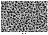
- the diameters of the solidified rods were between 1.2 and 1.5 mm and the eutectic microstructure consisted of MgO fibres embedded in a Ce 0.5 Zr 0.5 O 2 (Mg) matrix ( Figure 5 ).
- ⁇ eff ⁇ / ⁇ c ⁇ c ⁇ / ⁇ so ⁇ so ⁇ / ⁇ c ⁇ c + ⁇ / ⁇ so ⁇ so , where ⁇ c , ( ⁇ / ⁇ ) c and ⁇ so , ( ⁇ / ⁇ ) so are the conductivity and volume-fraction-to-tortuosity-factor ratio of carbonate and solid oxide phases, respectively, the conductivity of both the solid and molten carbonate phases impact performance.
- Figure 6 shows the total electrical conductivity of the carbonate-infiltrated MgSZ rod (blue triangles) and MgSZ-MgO eutectic sample (green squares), obtained from impedance spectroscopy measurements up to 600 °C (for carbonate infiltrated MgSZ) or 850 °C (for MgSZ-MgO eutectic).
- As-grown rods were ⁇ 1.5 mm diameter and -80 mm long. Each rod was cut into ⁇ 2 mm-long slices that were acid etched for ⁇ 20 days to dissolve the MgO fibres. To increase the effective membrane surface area, in a particular example that can be seen in Figure 7 seven MgSZ porous slices (1) were inserted into circular holes drilled on a 500 ⁇ m-thick YSZ ceramic plate (2). Ceramabond 885 was used to secure the rods within the plate.
- the support assembly formed by the seven etched rods was pasted to a 11-mm-diameter, 250-mm-long YSZ tube.
- a pellet of pressed carbonate powders was deposited on top of the support (3), then the tube was inserted into the membrane reactor, which was placed inside the furnace.
- the temperature was first increased from room temperature to 495 °C at 1 °C.min -1 under 30 ml.min -1 flow of composition 50%CO 2 /25%N 2 /25%O 2 , both at the feed and permeate side inlets.
- the sweep gas was switched to 30 ml.min -1 of high-purity Ar and the temperature was increased first to 565 °C and then from 565 to 815 °C in steps of 50 °C, with 7 or 10 h of holding time at each temperature step and 1 °C.min -1 ramp between steps.
- the outlet permeate-side gases were analysed using a mass spectrometer and an IR analyser.
- the CO 2 permeability is 0.83x10 -10 mol.m -1 .s -1 .Pa -1 at 765 °C and 1.41 x 10 -10 mol.m -1 .s -1 .Pa -1 at 815 °C, much higher than in ceramic membranes based on YSZ as ionic conducting phase ( ⁇ 10 -11 mol.m -1 .s -1 .Pa -1 at 850 °C in [ Wade et al., J. Membr. Sci. 369, 20 (2011 )] and 7.69 x 10 -13 mol.m -1 .s -1 .Pa -1 at 650 oC [ Lu et al., J. Membr. Sci. 444, 402 (2013 )]), despite the lower conductivity of MgSZ compared to YSZ.
- Plate-shaped porous MgSZ with micron-sized pores connected to the outer faces, with larger macroscopic dimensions than the ones we can achieve with the currently available LFZ technique, can be prepared by the procedure of surface laser melting.
Landscapes
- Chemical & Material Sciences (AREA)
- Chemical Kinetics & Catalysis (AREA)
- Inorganic Chemistry (AREA)
- Engineering & Computer Science (AREA)
- Manufacturing & Machinery (AREA)
- Dispersion Chemistry (AREA)
- Physics & Mathematics (AREA)
- Optics & Photonics (AREA)
- Analytical Chemistry (AREA)
- General Chemical & Material Sciences (AREA)
- Oil, Petroleum & Natural Gas (AREA)
- Compositions Of Oxide Ceramics (AREA)
Abstract
The invention relates to a molten salt-ceramic composite membrane, a process to obtain said composite, that comprises the etching of a fibrilar eutectic composition to produce a ceramic porous matrix and the infiltration of the matrix with molten carbonates and the use of said composite as a CO2 separator, wherein the pore alignment impacts on separation performance as do support and molten-salt conductivities, membrane thickness and pore volume fraction, size, connectivity and tortuosity factor.
Description
- The invention relates to a molten salt-ceramic composite membrane, a process to obtain said composite, that comprises the etching of a fibrilar eutectic composite to produce a ceramic porous matrix and the infiltration of the matrix with molten carbonates, and the use of said composite as a CO2 separator, wherein the pore alignment impacts on separation performance as do support and molten-salt conductivities, membrane thickness and pore volume fraction, size, connectivity and tortuosity factor.
- The climate change and the global warming induced by greenhouse effect gases, such as CO2, urge to search forms of separating the CO2 emitted in industrial processes as a previous step of its storage. Among devices that may serve to such goal, supported molten-salt membranes, also known as dual membranes, have attracted interest since their appearance in 2005 [Chung et al., Ind. Eng. Chem. Res. 44, 7999 (2005)]. In these devices, selectivity to CO2 is based on permeation of that gas through molten carbonates infiltrated in the pores of a support. For the case of a purely ionic (O2-) conducting support, the conventional understanding of how these membranes work assumes that CO3 2- anions are formed at the feed side through a surface reaction between the CO2 from the feed gas and oxide ions from the ceramic support. The CO3 2- anions thus formed diffuse through the molten carbonates and deliver CO2 at the permeate side through the reverse reaction.
- Membrane permeability depends both on intensive factors of the constituent materials, such as the support and molten salt conductivities, as on geometrical factors (membrane thickness) and support microstructural properties related to pores, such as pore diameter, tortuosity, connectivity between feed and permeate sides of the membrane, specific internal surface, contact surface between the molten salt and the atmosphere, etc. Achieving a good control of these parameters is crucial to obtain high permeability values. The relation between pore characteristics and membrane performance has been demonstrated in a number of works. In a samarium-doped ceria (SDC)-carbonate system, for instance, the conductivity increased linearly with the SDC-carbonate interfacial area, but was inversely proportional to the tortuosity factor [Y. Shilong et al., Mater. Lett. 92, 78 (2013)]. In a lanthanum strontium cobalt ferrite (LSCF)-carbonate system, permeability could be increased by decreasing either the carbonate or the solid-oxide tortuosity [J. Ortiz-Landeros et al., Chem. Eng. Sci. 104, 891 (2013)].
- In membranes prepared at the laboratory scale by techniques such as isostatic pressing or tape-casting, porosity control relies upon the use of sacrificial materials as pore formers. Sacrificial materials are also used in the phase-inversion technique, currently applied to produce supports in tubular form, with the goal of obtaining dimensions closer to those required for large-scale applications. However, although a relatively good control of pore diameter and total support porosity has been achieved with these methods, an adequate control of the pore alignment in the direction of the gas transport is still lacking, especially for pore diameters in the 1-50 µm range.
- The present invention discloses a novel molten salt-ceramic composite membrane, wherein the etching of the minority phase in a fibrilar eutectic can be used to produce a membrane support with geometrical and microstructural properties difficult to achieve by other methods with a higher permeability than in the state-of-the-art values. The present invention takes benefit of the natural ordering of eutectic by crystals to produce a porous support that, after infiltration with molten carbonates, allows the CO2 transport through the liquid in the form of carbonate anions. Different solidification techniques may be used to produce the parent eutectic system, basically unidirectional solidification or surface melting, providing solidified materials with different sizes and geometrical shapes. The porous support is obtained from the eutectic by crystal by dissolution of the minority phase through etching. If the parent material is a fibrilar eutectic, fibre dissolution results in a porous matrix with highly dense and well aligned parallel pores of very uniform diameter.
- A first aspect of the present invention is related to a molten salt-ceramic composite membrane characterized in that it comprises
- a porous ceramic oxide support with a conductivity measured by impedance spectroscopy of between 3.5x10⁻³ and 15 S m-1 at a temperature of between 600 to 840 °C, wherein the porosity determined from weight loss after acid etching or X-ray tomography is between 10 and 35% and the pore diameter range measured by scanning electron microscopy (SEM) is between 0.2 to 5 µm, and wherein the tortuosity factor is between 1 and 3, and wherein the specific surface area of the support is between 0.2
y 6 µm-1; and - at least one alkali metal carbonate melted and infiltrated into the pores of the ceramic oxide support.
- The term "tortuosity factor" as used herein refers to the alignment of the pores along the material. A better alignment decreases the tortuosity (the optimal value of the tortuosity factor = 1 would be reached in the ideal situation of perfect alignment) and enhances the flow of CO2 through the membrane, thus improving its permeability. The micrometric diameter of the pores, as well as their high density, result in high values of both the specific surface (SS) area (internal pore surface area versus volume of the support) and the length of the TPB (triple phase boundary) reaction points, where the gas (atmosphere), liquid (molten salts) and solid (ceramic support) phases meet. Therefore, increases in TPB and SS will facilitate permeation. A high permeability value was obtained, which was attributed to the excellent pore and solid-oxide microstructural characteristics: good pore connectivity and alignment, high pore specific density and homogeneous micrometric pore size. These properties are specific to the directional-solidification preparation process and add to the properties common to supported molten-salt membranes, such as suitability for high-temperature operation and very high CO2/N2 selectivity. The specific surface area of the porous ceramic oxide support is between 0.2
y 6 µm-1 and said value in accordance with the pore dimensions and porosity values of the support. - Thus, a preferred embodiment of the composite of the present invention the porous ceramic oxide support is a 1-2 mm diameter solidified rod or a 0.3 -1 mm thick eutectic plate of 1-50 cm2 surface.
- In other preferred embodiment of the composite of the present invention the porous ceramic oxide matrix is selected from magnesium-stabilised zirconia Zr1-xMgxO2-z (0.10 ≤ x ≤ 0.25) (MgSZ), Zr1-x-yYxMgyO2-z (x ≤ 0.45, y ≤ 0.25), Zr1-x-yHfxMgyO2-z (x ≤ 0.45, y ≤ 0.25), Zr1-x-yCexMgyO2-z (x ≤ 0.45, y ≤ 0.25), Ce1-x-ySmxMgyO2-z (x ≤ 0.25, y ≤ 0.25), Ce1-x-yGdxMgyO2-z (x ≤ 0.25, y ≤ 0.25), and any combination thereof.
- In a further embodiment where the ceramic oxide matrix is MgSZ, the measured CO2 permeability is much higher than those reported for YSZ (Zr1.85Y0.15O1.925)-based supported molten-salt membranes, despite the conductivity of MgSZ being approximately one order of magnitude lower than that of YSZ. The high permeability therefore may be attributed to the improved pore characteristics: good connectivity between the feed side and the permeate side of the membrane, alignment along the permeation direction, very homogeneous pore size, high specific surface and high contact surface between the feed gas and the molten salt. The ordered pore distribution also reduces the ceramic support tortuosity factor.
- In other preferred embodiment, the molten salt infiltrated in the porous ceramic matrix is a mixture of Li2CO3, Na2CO3 and K2CO3 carbonates, preferably in the ternary eutectic proportion of 42.5/32.5/25 mol% respectively. Using this carbonate proportion, the melting temperature of the carbonate mixture is lowered to T∼400 ºC. Single or binary carbonate mixtures can also be used, with higher melting temperatures (T ≥ 490 ºC).
- A second aspect of the present invention is a process to obtain the composite described above characterized in that it comprises the following steps
- a) mixing a combination of inorganic oxides with a eutectic composition, and sintering at a temperature up to 1600 ºC;
- b) melting the mixture obtained in step (a) at a temperature between 1800 and 2500 °C, followed by solidification at a controlled rate of between 1 and 500 mm/h and cooling to a temperature between 10 ºC and 30 ºC;
- c) immersing the product obtained in step (b) into a solution of an acid selected from HCI, H2SO4, HNO3 and acetic acid in distilled water at a temperature of between 10 ºC and 90 °C for a time of between 10 and 500 h; and
- d) depositing in compacted powder form at least an alkali metal carbonate on top of the support material obtained in step (c) and heating above the melting temperature of the alkali-metal carbonate or carbonate mixture so that the carbonates infiltrate the pores of the support.
- The term "eutectic composition" as used herein refers to a mixture of compounds at a proportion corresponding to an invariant point in the composition-temperature phase diagram in which a homogenous liquid is in equilibrium with two (or more) crystalline solid phases.
- The term "eutectic temperature" as used herein refers to the temperature corresponding to an invariant point in the composition-temperature phase diagram of a mixture of compounds at which a homogenous liquid is in equilibrium with two (or more) crystalline solid phases.
- With respect to the mixture of oxides referred to herein, the phases are considered to be oxides with fixed stoichiometry, and the solidification is performed by cooling the molten mixture (with "eutectic composition") below its melting point (the "eutectic temperature") to generate simultaneously the two solid oxides. More loosely, the terms "eutectic composition" and "eutectic temperature" are used herein also to refer to compositions that might involve also a third (or more) component oxide and that allows the homogenous and coupled growth of two solid phases by cooling a liquid directionally below its melting temperature. The extra component will in this case incorporate in one or both phases forming solid solutions.
- With respect to carbonate mixtures, the eutectic composition is one preferred composition herein as it is the one that gives the minimum melting temperature of mixtures of the selected carbonates.
- In a preferred embodiment of the process of the present invention, the mixture of a combination of inorganic oxides of step (a) comprises a first oxide selected from ZrO2, Y2O3, HfO2, CeO2, Ce2O3, Sm2O3, Gd2O3, YSZ and a combination thereof, and a second oxide selected from MgO, NiO, CoO or a combination thereof, wherein the proportion between the first and second oxide is between 40:60 to 60:40 respectively and it corresponds to the eutectic composition ± 10 mol%.
- In a further preferred embodiment the combination of inorganic oxides in step (a) are zirconium oxide (ZrO2) and magnesium oxide (MgO), wherein the mixture is 47:53 mol% ZrO2:MgO. In an even further preferred embodiment, the sintering temperature of step (a) is between 1450 ºC and 1550 ºC.
- In another further preferred embodiment the combination of inorganic in step (a) oxides are yttria-stabilized zirconia (YSZ) and magnesium oxide (MgO), wherein the mixture is 49:51 mol% YSZ:MgO.
- In another further preferred embodiment the combination of inorganic oxides in step (a) are Ce0.5Zr0.5O2 (CZO) and magnesium oxide (MgO) wherein the mixture is 52:48 mol% CZO:MgO.
- In another preferred embodiment of the process of the present invention the melting of step (b) of the mixture of oxides is produced by a technique selected from laser assisted directional solidification (LFZ) and laser assisted surface melting and solidification.
- In another further preferred embodiment, the combination of inorganic oxides in step (a) are ZrO2 and magnesium oxide (MgO), wherein the mixture is 47:53 mol% ZrO2-MgO and the melting of step (b) of the mixture of oxides is produced by laser-assisted directional solidification. Said method resulting in 1-2 mm diameter solidified rods.
- In another preferred embodiment, the combination of inorganic oxides in step (a) are ZrO2 and magnesium oxide (MgO), wherein the mixture is 47:53mol% ZrO2-MgO and the melting of step (b) of the mixture of oxides is produced by laser-assisted surface melting and solidification. Said method resulting in 0.3 -1 mm thick eutectic plates of 1-50 cm2 surface.
- A third aspect of the present invention relates to the use of the composite described above as a CO2 separator at a temperature of between 550 ºC and 900 ºC, preferably the temperature is between 600 and 750 ºC. At said temperature carbonate or support reactivity are avoided. This is also an adequate temperature range for industrial processes.
- A fourth aspect of the present invention is a membrane system characterized in that it comprises a plurality of the molten salt-ceramic composite membranes described above located laterally adjacent to each other.
- In a preferably embodiment of the membrane system each molten salt-ceramic composite membrane is a rod wherein said rod has a diameter of between 1 mm and 2 mm, and a thickness of between 0.5 mm and 2 mm. In another preferred embodiment each molten salt-ceramic composite membrane is a flat disk wherein said flat disk has a thickness of between 0.3 mm and 1 mm and 1-50 cm2 surface.
- In a preferably embodiment of the membrane system each composite is glued to each other with ceramic cement.
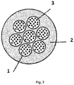
- In a preferred embodiment of the system of the present invention it comprises seven molten salt-ceramic composite membranes, wherein membranes are inserted into circular holes which are laser-drilled in a 500 µm-thick YSZ ceramic plate. Said ceramic cement is used to secure the rods within the plate, for mechanical stability. The ceramic cement covers all the YSZ plate surface around the membranes.
- A fifth aspect of the present invention is a procedure to use the system described above in the present invention characterized in that it comprises the following steps
- i. attaching the membrane described above to a gas outlet conduction, preferably a flue gas exit conduction; and
- ii. feeding a gas flow through the membrane of step i) of at least of 20 ml.min-1, wherein said gas comprises at least CO2, with at least other gas selected from N2, H2, CO, H2O, SOx, NOx, O2, CH4, NH3 and any combination thereof, at a temperature of between 550 ºC and 850 ºC, preferably the temperature is between 600 and 750 ºC.
- Unless otherwise defined, all technical and scientific terms used herein have the same meaning as commonly understood by one of ordinary skilled in the art to which this invention belongs. Methods and materials similar or equivalent to those described herein can be used in the practice of the present invention. Throughout the description and claims the word "comprise" and its variations are not intended to exclude other technical features, additives, components, or steps. Additional objects, advantages and features of the invention will become apparent to those skilled in the art upon examination of the description or may be learned by practice of the invention. The following examples and drawings are provided by way of illustration and are not intended to be limiting of the present invention.
-
-
Fig. 1 . ZrO2-MgO phase diagram. -
Fig. 2 . Electron micrograph of the transverse section (perpendicular to the growth axis) of an MgSZ-MgO eutectic solidified at 25 mm.h-1 after etching, depicting an array of micrometric pores (dark grayscale) embedded into the ceramic matrix. -
Fig. 3 . Schematics of the etching and infiltration steps applied to the as-grown MgSZ-MgO eutectic rods. -
Fig. 4 . Electron micrograph of the transverse section (perpendicular to the growth axis) of the eutectic of the YSZ:MgO system solidified at 25 mm.h-1, depicting an array of micrometric fibres (dark grayscale) embedded into the ceramic matrix. -
Fig. 5 . Electron micrograph of the transverse section (perpendicular to the growth axis) of the eutectic of the CZO:MgO system solidified at 25 mm.h-1, depicting an array of micrometric fibres (dark grayscale) embedded into the ceramic matrix. -
Fig. 6 . Total electrical conductivity of the MgSZ porous matrix infiltrated with carbonates (1, circles) and MgSZ-MgO as grown eutectic (2, squares). Thearrow 3 indicates the melting temperature of the eutectic mixture of Li, Na and K carbonates. -
Fig. 7 . Arrangement of seven infiltrated transverse rod portions forming the membrane to be used in the permeation experiment. For the permeation experiments, carbonates were infiltrated after the seven etched rods were pasted to the support. -
Fig. 8 . CO2 and O2 permeabilities of the membrane prepared by infiltrating the mixture of Li, Na, K carbonates with ternary eutectic composition into the porous MgSZ matrix obtained from the MgSZ-MgO fibrilar eutectic after etching the MgO phase. - Rods of 47:53 mol% ZrO2:MgO, according to the ZrO2-MgO phase diagram (
Figure 1 [Phase Equilibria Diagrams Online Database (NIST Standard Reference Database 31), The American Ceramic Society and the National Institute of Standards and Technology, 2020. Figure Number Zr-076-A, Y. Yin and B. B. Argent, J. Phase Equilib., 14 [4] 439-450 (1993).]), were directionally solidified using the laser floating zone (LFZ) method, where a drop of a sample is melted by focussing a high-power CO2 laser on a small volume of the feedstock material as it moves vertically. To prepare the feedstock rods, commercial powders of ZrO2 (Aldrich, 99%) and MgO (Alfa Aesar, 99.99%) were mixed in the appropriate amount, isostatically pressed for 3 min at 200 MPa and sintered at 1500 °C for 12 h in an open furnace. Rods of -80 mm length were melted and solidified in air using 80-100 W of a CO2 laser as a heating source at rates varying between 10 and 100 mm.h-1. The diameters of the solidified rods were between 1.2 and 1.5 mm. At the eutectic temperature the liquid crystallizes in the form of a quasi-hexagonal lattice of micron-sized MgO fibres embedded within a magnesium-stabilised zirconia (MgSZ) cubic phase with ∼20% Mg2+ content (Figure 2 ). - Sections of the rods were acid-etched by immersion in a 1 M solution of HCI in distilled water at 60 °C. The degree of etching was determined from the weight loss of the sample relative to the weight proportion of the MgO fibres in the MgSZ-MgO eutectic. MgO weight losses between 80 and 90% were achieved after acid treatments of at least 20 days, resulting in a support porosity in the 22 to 27% range.
- X-ray nano-CT of a 32,100 µm3 sample volume of the porous matrix resulting from etching yielded a 20.5% of open porosity with pores aligned along the growth direction and with misalignment in perpendicular directions smaller than 10º. More than 76% of the open pores percolated from one side of the membrane to the other side. The volume-specific internal surface area was -0.8 µm-1 for the percolating pores, which is in agreement with the value expected from the geometrical parameters of the parent eutectic microstructure. The slight pore misalignment found in tomography experiments is attributed to the curvature of the solidification front during melting. For typical support diameters and thicknesses above ∼1 mm misalignment may result in a significant reduction of the proportion of pores percolating between both sides of the membrane. Therefore, the supports must be as thin as possible.
- Infiltration of the carbonates into the porous matrix obtained in example 1.
- For that purpose, a mixture of Li2CO3, Na2CO3 and K2CO3 carbonates in the ternary eutectic proportion (42.5/32.5/25 mol%, respectively) (4) was deposited in compacted powder form on top of the MgSZ (1) porous sample obtained in example 1 after the etching step of the MgO (2), and heated above the eutectic temperature of the carbonate mixture (397 °C) to allow the carbonates (4) to melt and infiltrate the pores (3) by capillarity so as to obtain a molten salt-ceramic composite membrane. A scheme of the last two steps is shown in
Figure 3 . - Rods of 49:51 mol% YSZ:MgO composition were directionally solidified using the laser floating zone (LFZ) method at a growth rate of 25 mm.h-1, in the same manner as in Example 1, using commercial powders of ZrO2 (Aldrich, 99%), Y2O3 (Aldrich, 99.99%) and MgO (Alfa Aesar, 99.99%) as reactants to prepare the feedstock material. The diameters of the solidified rods were between 1.2 and 1.5 mm and the eutectic microstructure consisted of MgO fibres embedded in a YSZ(Mg) matrix (
Figure 4 ). - Rods of 52:48 mol% CZO:MgO composition (
Figure 8 ), were directionally solidified using the laser floating zone (LFZ) method at a growth rate of 25 mm.h-1, in the same manner as in Example 1, using commercial powders of ZrO2 (Aldrich, 99%), CeO2 (Aldrich, 99.9%) and MgO (Alfa Aesar, 99.99%) as reactants to prepare the feedstock material. The diameters of the solidified rods were between 1.2 and 1.5 mm and the eutectic microstructure consisted of MgO fibres embedded in a Ce0.5Zr0.5O2(Mg) matrix (Figure 5 ). - According to the equation of the effective ambipolar conductivity:

Figure 6 shows the total electrical conductivity of the carbonate-infiltrated MgSZ rod (blue triangles) and MgSZ-MgO eutectic sample (green squares), obtained from impedance spectroscopy measurements up to 600 °C (for carbonate infiltrated MgSZ) or 850 °C (for MgSZ-MgO eutectic). - The conductivity observed for the MgSZ-MgO eutectic is identical to the one reported in [R.I. Merino et al., )]. The conductivity of the sample infiltrated with carbonates increased at the carbonate melting temperature (∼400 °C), as expected [H. Näfe, Conductivity of Alkali Carbonates, Carbonate-Based Composite Electrolytes and IT-SOFC, ECS J. Solid State Science and Technology 3 (2014) N7-N14].
- As-grown rods were ∼1.5 mm diameter and -80 mm long. Each rod was cut into ∼2 mm-long slices that were acid etched for ≥20 days to dissolve the MgO fibres. To increase the effective membrane surface area, in a particular example that can be seen in
Figure 7 seven MgSZ porous slices (1) were inserted into circular holes drilled on a 500 µm-thick YSZ ceramic plate (2). Ceramabond 885 was used to secure the rods within the plate. - The support assembly formed by the seven etched rods was pasted to a 11-mm-diameter, 250-mm-long YSZ tube. A pellet of pressed carbonate powders was deposited on top of the support (3), then the tube was inserted into the membrane reactor, which was placed inside the furnace. The temperature was first increased from room temperature to 495 °C at 1 °C.min-1 under 30 ml.min-1 flow of composition 50%CO2/25%N2/25%O2, both at the feed and permeate side inlets. Then, the sweep gas was switched to 30 ml.min-1 of high-purity Ar and the temperature was increased first to 565 °C and then from 565 to 815 °C in steps of 50 °C, with 7 or 10 h of holding time at each temperature step and 1 °C.min-1 ramp between steps. The outlet permeate-side gases were analysed using a mass spectrometer and an IR analyser.
- Permeability example. The table lists the CO2 permeabilities obtained for a membrane using a porous MgSZ support obtained through the procedure described in Example 1. The high temperature CO2 permeability was measured in a membrane reactor operated at atmospheric pressure, following the procedure described in Example 6.
Sample support material T (°C) Permeability mol.m-1.s-1.Pa-1 Example 1-2-6 Product MgSZ 815 1.41 x 10⁻¹⁰ Example 1-2-6 Product MgSZ 765 8.33 x 10⁻¹¹ Example 1-2-6 Product MgSZ 665 1.06 x10⁻¹¹ -
Figure 8 shows the CO2 (P CO2) and O2 (P O2) permeabilities obtained from the measured fluxes (J CO2 and J O2) through the expression P= J i .t/(p i-po), where t is the membrane thickness and p, p o are the CO2 or O2 partial pressures at the feed and permeate sides, respectively. The CO2 permeability is 0.83x10⁻¹⁰ mol.m-1.s-1.Pa-1 at 765 °C and 1.41 x 10⁻¹⁰ mol.m-1.s-1.Pa-1 at 815 °C, much higher than in ceramic membranes based on YSZ as ionic conducting phase (∼10-11 mol.m-1.s-1.Pa-1 at 850 °C in [Wade et al., J. Membr. Sci. 369, 20 (2011)] and 7.69 x 10⁻¹³ mol.m-1.s-1.Pa-1 at 650 ºC [Lu et al., J. Membr. Sci. 444, 402 (2013)]), despite the lower conductivity of MgSZ compared to YSZ. - Comparative example of the permeability obtained with the present invention and permeability values reported in the literature.
Reference Support material T (°C) Permeability mol.m-1.s-1.Pa-1 Wade et al., J. Membr. Sci. 369, 20 (2011) YSZ 850 9 x 10-12 Lu et al., J. Membr. Sci. 444, 402 (2013) YSZ 650 7.69x10⁻¹³ Example 1-2-6 Product MgSZ 815 1.41 x 10⁻¹⁰ Example 1-2-6 Product MgSZ 765 8.33 x 10⁻¹¹ Example 1-2-6 Product MgSZ 665 1.06 x10⁻¹¹ Gili et al., Membranes 9, 108 (2019) SDC 900 7.59 x 10⁻¹¹ SDC:Fe 900 1.31 x10⁻¹⁰ Norton et al., J. Membr. Sci. 467, 244 (2014) SDC 900 1.52 x10⁻¹⁰ Dong et al., J. Membr. Sci. 564, 73 (2018) SDC 900 3.79×10⁻¹¹ Chen et al., J. Membr. Sci. 597, 117770 (2020) SDC 700 1.06 x 10⁻¹⁰ - This table shows that the permeability values obtained with the membrane object of the present invention (example 1-2-6) are much higher than those obtained with YSZ supports, and are similar to the best values obtained with supports of SDC, a material with even higher conductivity than YSZ in the 600-900 ºC temperature range.
- Plate-shaped porous MgSZ, with micron-sized pores connected to the outer faces, with larger macroscopic dimensions than the ones we can achieve with the currently available LFZ technique, can be prepared by the procedure of surface laser melting. Ceramic prisms with the composition 47:53 mol% ZrO2:MgO, according to the ZrO2-MgO phase diagram (
Figure 1 ), were pressed and then sintered at ∼1500 ºC. The size of the prisms was ∼10 x 20 x 2 mm3. Then, the sample was subjected to surface melting and solidification using a CO2 laser. The procedure is similar to the one used in reference [J. Gurauskis, et al. "Laser-assisted, crack-free surface meeting of large eutectic ceramic bodies". J. Europ. Ceram. Soc 31 (2011) 1251. DOI:10.1016/j.jeurceramsoc.2010.08.017]. In the present case the preheating was between 1200 and 1500 ºC and the sample travelling rate was comprised between 50 and 150 mm h-1. The laser power was adjusted to form a molten pool with a depth of ∼1 mm. - After cooling and extraction from the furnace, the unmelted part of the sample was removed by cutting, lapping and polishing. The upper part was also lapped and polished. Finally, a slice of around 0.5 mm depth was obtained, with approximate transverse dimensions of 8 x 4 mm2. This piece was acid-etched by immersion in a 1M solution of HCI in distilled water at 60 ºC. The total sample weight loss was 21%, indicative of full MgO dissolution.
Claims (15)
- Molten salt-ceramic composite membrane characterized in that it comprises• a porous ceramic oxide support with a conductivity measured by impedance spectroscopy of between 3.5x10⁻³ and 15 S m-1 at a temperature of between 600 to 840 °C, wherein the porosity determined from weight loss after acid etching or X-ray tomography is between 10 and 35% and the pore diameter range measured by scanning electron microscopy is between 0.2 to 5 µm, and wherein the tortuosity factor is between 1 and 3, and wherein the specific surface area of the support is between 0.2 and 6 µm-1; and• at least one alkali metal carbonate melted and infiltrated into the pores of the ceramic oxide support.
- Composite according to claim 1, wherein porous ceramic oxide support is a 1-2 mm diameter solidified rod or a 0.3 -1 mm thick eutectic plate of 1-50 cm2 surface.
- Composite according to any of claim 1 or 2, wherein the porous ceramic oxide matrix is selected from Zr1-xMgxO2-z (0.10 ≤ x ≤ 0.25), Zr1-x-yYxMgyO2-z (x ≤ 0.45, y ≤ 0.25), Zr1-x-yHfxMgyO2-z (x ≤ 0.45, y ≤ 0.25), Zr1-x-yCexMgyO2-z (x ≤ 0.45, y ≤ 0.25), Ce1-x-ySmxMgyO2-z (x ≤ 0.25, y ≤ 0.25), Ce1-x-yGdxMgyO2-z (x ≤ 0.25, y ≤ 0.25), and any combination thereof.
- Composite according to any of claims 1 to 3, wherein the alkali metal carbonate melted is a mixture of Li2CO3, Na2CO3 and K2CO3, preferably in the ternary eutectic proportion of 42.5/32.5/25 mol% respectively.
- The process to obtain the composite according to claims 1 to 4, characterized in that it comprises the following stepsa) mixing a combination of inorganic oxides with a eutectic composition, and sintering at a temperature up to 1600 ºC;b) melting the mixture obtained in step (a) at a temperature between 1800 and 2500 °C, followed by solidification at a controlled rate of between 1 and 500 mm/h and cooling to a temperature between 10 ºC and 30 ºC;c) immersing the product obtained in step (b) into a solution of an acid selected from HCI, H2SO4, HNO3 and acetic acid in distilled water at a temperature of between 10 ºC and 90 °C for a time of between 10 and 500 h; andd) depositing in compacted powder form at least an alkali metal carbonate on top of the support material obtained in step (c) and heating above the melting temperature of the alkali-metal carbonate or carbonate mixture so that the carbonates infiltrate the pores of the support.
- Process according to claim 5, wherein the mixture of a combination of inorganic oxides of step (a) comprises a first oxide selected from ZrO2, Y2O3, HfO2, CeO2, Ce2O3, Sm2O3, Gd2O3, YSZ and any combination thereof, and a second oxide selected from MgO, NiO, CoO or a combination thereof, wherein the proportion between the first and second oxide is between 40:60 to 60:40 respectively and it corresponds to the eutectic composition ± 10 mol%.
- Process according to claim 5, wherein the combination of inorganic oxides are selected from zirconium oxide (ZrO2) and magnesium oxide (MgO), wherein the mixture is 47:53 mol% ZrO2:MgO or YSZ and MgO in proportion 49:51 mol% YSZ:MgO or are Ce0.5Zr0.5O2 (CZO) and MgO in proportion 52:48 mol% CZO:MgO.
- Process according to any of claims 5 to 7, wherein the melting of step (b) of the mixture of oxides is produced by a technique selected from laser assisted directional solidification (LFZ) and laser assisted surface melting and solidification.
- Process according to claim 8, wherein the combination of inorganic oxides in step (a) are zirconium oxide and magnesium oxide (MgO), wherein the mixture is 47:53 mol% ZrO2-MgO and the melting of step (b) of the mixture of oxides is produced by laser assisted directional solidification.
- Process according to claim 8, wherein the combination of inorganic oxides in step (a) are zirconium oxide and magnesium oxide (MgO), wherein the mixture is 47:53 mol% ZrO2-MgO and the melting of step (b) of the mixture of oxides is produced by laser assisted surface melting and solidification.
- Use of the composite according to any of claims 1 to 4 as a CO2 separator at a temperature of between 550 ºC and 900 ºC.
- A membrane system characterized in that it comprises a plurality of the molten salt-ceramic composite membranes according to any claims 1 to 4 located laterally adjacent to each other and each composite is glued to each other with ceramic cement.
- Membrane system according to claim 12, wherein each molten salt-ceramic composite membrane is a rod wherein said rod has a diameter of between 1 mm and 2 mm, and a thickness of between 0.5 mm and 2 mm or each molten salt-ceramic composite membrane is a flat disk wherein said flat disk has a thickness of between 0.3 mm and 1 mm and 1-50 cm2 surface.
- Membrane system according to any claims 12 to 13, comprising seven molten salt-ceramic composite membranes, wherein membranes are inserted into circular holes which are laser-drilled in a 500 µm-thick YSZ ceramic plate.
- A procedure to use the membrane system to claims 12 to 14 characterized in that it comprises the following stepsi. attaching the membrane of claims 1 to 4 to a gas outlet conduction, preferably a flue gas exit conduction; andii. feeding a gas flow through the membrane of step i) of at least of 20 ml.min-1, wherein said gas comprises at least CO2, with at least other gas selected from N2, H2, CO, H2O, SOx, NOx, O2, CH4, NH3 and any combination thereof, at a temperature of between 550 ºC and 850 ºC, preferably the temperature is between 600 and 750 ºC.
Priority Applications (1)
| Application Number | Priority Date | Filing Date | Title |
|---|---|---|---|
| EP21382302.4A EP4070879A1 (en) | 2021-04-09 | 2021-04-09 | Molten salt-ceramic composite membrane with high co2 permeability |
Applications Claiming Priority (1)
| Application Number | Priority Date | Filing Date | Title |
|---|---|---|---|
| EP21382302.4A EP4070879A1 (en) | 2021-04-09 | 2021-04-09 | Molten salt-ceramic composite membrane with high co2 permeability |
Publications (1)
| Publication Number | Publication Date |
|---|---|
| EP4070879A1 true EP4070879A1 (en) | 2022-10-12 |
Family
ID=75529956
Family Applications (1)
| Application Number | Title | Priority Date | Filing Date |
|---|---|---|---|
| EP21382302.4A Withdrawn EP4070879A1 (en) | 2021-04-09 | 2021-04-09 | Molten salt-ceramic composite membrane with high co2 permeability |
Country Status (1)
| Country | Link |
|---|---|
| EP (1) | EP4070879A1 (en) |
Cited By (2)
| Publication number | Priority date | Publication date | Assignee | Title |
|---|---|---|---|---|
| CN116199513A (en) * | 2023-04-28 | 2023-06-02 | 内蒙古工业大学 | Three-layer ceramic carbonate biphase film with sandwich structure, and preparation method and application thereof |
| CN118479881A (en) * | 2024-05-08 | 2024-08-13 | 上海大学 | Ceramic-carbonate compact biphase inorganic membrane material and preparation method thereof |
-
2021
- 2021-04-09 EP EP21382302.4A patent/EP4070879A1/en not_active Withdrawn
Non-Patent Citations (12)
| Title |
|---|
| CHUNG ET AL., IND. ENG. CHEM. RES., vol. 44, 2005, pages 7999 |
| GRIMA L. ET AL: "High CO2 permeability in supported molten-salt membranes with highly dense and aligned pores produced by directional solidification", JOURNAL OF MEMBRANE SCIENCE, vol. 630, 12 January 2021 (2021-01-12), NL, pages 119057, XP055834038, ISSN: 0376-7388, Retrieved from the Internet <URL:https://reader.elsevier.com/reader/sd/pii/S0376738821000107?token=A0A999E557292088B24A4A95685232467A2BE969F8FCC951AE9EEC1FFD8E74CF23F9362C4258557D2294C9755B0F4742&originRegion=eu-west-1&originCreation=20210824064549> [retrieved on 20210823], DOI: 10.1016/j.memsci.2021.119057 * |
| GRIMA, L ET AL.: "High CO2 permeability in supported molten-salt membranes with highly dense and aligned pores produced by directional solidification: Supplementary Information", DATABASE J. PHASE EQUILIB, 12 January 2021 (2021-01-12), pages 439 - 450, XP055834078, Retrieved from the Internet <URL:https://ars.els-cdn.com/content/image/1-s2.0-S0376738821000107-mmc1.pdf> [retrieved on 20210823] * |
| GURAUSKIS J ET AL: "Laser-assisted, crack-free surface melting of large eutectic ceramic bodies", JOURNAL OF THE EUROPEAN CERAMIC SOCIETY, vol. 31, no. 7, 15 September 2010 (2010-09-15), pages 1251 - 1256, XP028186948, ISSN: 0955-2219, [retrieved on 20100819], DOI: 10.1016/J.JEURCERAMSOC.2010.08.017 * |
| H. NAFE: "Conductivity of Alkali Carbonates, Carbonate-Based Composite Electrolytes and IT-SOFC", ECS J. SOLID STATE SCIENCE AND TECHNOLOGY, vol. 3, 2014, pages N7 - N14 |
| J. GURAUSKIS ET AL.: "Laser-assisted, crack-free surface meeting of large eutectic ceramic bodies", J. EUROP. CERAM. SOC, vol. 31, 2011, pages 1251, XP028186948, DOI: 10.1016/j.jeurceramsoc.2010.08.017 |
| J. ORTIZ-LANDEROS ET AL., CHEM. ENG. SCI., vol. 104, 2013, pages 891 |
| LU ET AL., J. MEMBR. SCI., vol. 444, 2013, pages 402 |
| R.I. MERINO ET AL., SOLID STATE IONICS, vol. 100, 1997, pages 313 |
| WADE ET AL., J. MEMBR. SCI., vol. 369, no. 20, 2011 |
| Y. SHILONG ET AL., MATER. LETT., vol. 92, 2013, pages 78 |
| Y. YINB. B. ARGENT, J. PHASE EQUILIB., vol. 14, no. 4, 1993, pages 439 - 450 |
Cited By (2)
| Publication number | Priority date | Publication date | Assignee | Title |
|---|---|---|---|---|
| CN116199513A (en) * | 2023-04-28 | 2023-06-02 | 内蒙古工业大学 | Three-layer ceramic carbonate biphase film with sandwich structure, and preparation method and application thereof |
| CN118479881A (en) * | 2024-05-08 | 2024-08-13 | 上海大学 | Ceramic-carbonate compact biphase inorganic membrane material and preparation method thereof |
Similar Documents
| Publication | Publication Date | Title |
|---|---|---|
| AU2006200744B2 (en) | Method of making an ion transport membrane oxygen separation device | |
| EP2012381B1 (en) | Electrode-Electrolyte Composite Particles for a Fuel Cell and Method for the Preparation thereof | |
| Büchler et al. | Preparation and properties of thin La1− xSrxCo1− yFeyO3− δ perovskitic membranes supported on tailored ceramic substrates | |
| US10008731B2 (en) | Ceria electrolyte for low-temperature sintering and solid oxide fuel cell using the same | |
| KR20160004310A (en) | Channeled articles and methods for their manufacture | |
| KR20130023234A (en) | Microreactor comprising a porous ceramic material | |
| KR20130019411A (en) | Ceramic material comprising frustoconical tubular pores | |
| EP4393898A1 (en) | Preparation method for multilayer ceramic membrane having oxide thin layer, and application | |
| CN107851804A (en) | Electrolyte layer anode composite part for fuel cell and manufacturing method thereof | |
| Mu et al. | Engineering of microstructures of protonic ceramics by a novel rapid laser reactive sintering for ceramic energy conversion devices | |
| Lemes-Rachadel et al. | Current developments of mixed conducting membranes on porous substrates | |
| Li et al. | Single-step fabrication of asymmetric dual-phase composite membranes for oxygen separation | |
| He et al. | Tailoring of surface modified ultrathin membranes with CO 2 tolerance and high oxygen permeability | |
| Fontaine et al. | CO2 removal at high temperature from multi-component gas stream using porous ceramic membranes infiltrated with molten carbonates | |
| JP4332639B2 (en) | Fuel cell and method for producing the same | |
| JP4993496B2 (en) | Oxygen separation membrane and method for producing the same | |
| Gao et al. | Influence of high-energy ball milling of the starting powder on the sintering; microstructure and oxygen permeability of Ba0. 5Sr0. 5Co0. 5Fe0. 5O3− δ membranes | |
| Coors | Co-ionic Conduction in Protonic Ceramics of the Solid Solution, BaCexZr (yx) Y (1-y) O3-d; Part I: Fabrication and Microstructure | |
| Guesnet et al. | Densification study of Pr6O11 as a limiting step for the determination of its oxygen transport properties | |
| JP2006344543A (en) | Method for producing cell for solid oxide fuel cell | |
| JP2012514827A (en) | Method for producing nickel cermet electrode | |
| JP2008047445A (en) | Method of manufacturing solid electrolytic ceramic membrane, and electrochemical device | |
| KR20220139612A (en) | High permeability membrane for oxygen separation and fabrication method thereof | |
| Zhu et al. | Critical factors affecting oxygen permeation through dual-phase membranes | |
| Athayde et al. | Perovskite membranes for oxygen separation |
Legal Events
| Date | Code | Title | Description |
|---|---|---|---|
| PUAI | Public reference made under article 153(3) epc to a published international application that has entered the european phase |
Free format text: ORIGINAL CODE: 0009012 |
|
| STAA | Information on the status of an ep patent application or granted ep patent |
Free format text: STATUS: THE APPLICATION HAS BEEN PUBLISHED |
|
| AK | Designated contracting states |
Kind code of ref document: A1 Designated state(s): AL AT BE BG CH CY CZ DE DK EE ES FI FR GB GR HR HU IE IS IT LI LT LU LV MC MK MT NL NO PL PT RO RS SE SI SK SM TR |
|
| STAA | Information on the status of an ep patent application or granted ep patent |
Free format text: STATUS: THE APPLICATION IS DEEMED TO BE WITHDRAWN |
|
| 18D | Application deemed to be withdrawn |
Effective date: 20230413 |