EP4070875A1 - Multi waste processor - Google Patents
Multi waste processor Download PDFInfo
- Publication number
- EP4070875A1 EP4070875A1 EP22166827.0A EP22166827A EP4070875A1 EP 4070875 A1 EP4070875 A1 EP 4070875A1 EP 22166827 A EP22166827 A EP 22166827A EP 4070875 A1 EP4070875 A1 EP 4070875A1
- Authority
- EP
- European Patent Office
- Prior art keywords
- processing chamber
- waste
- gas
- water
- liquid waste
- Prior art date
- Legal status (The legal status is an assumption and is not a legal conclusion. Google has not performed a legal analysis and makes no representation as to the accuracy of the status listed.)
- Pending
Links
Images


Classifications
-
- B—PERFORMING OPERATIONS; TRANSPORTING
- B01—PHYSICAL OR CHEMICAL PROCESSES OR APPARATUS IN GENERAL
- B01D—SEPARATION
- B01D53/00—Separation of gases or vapours; Recovering vapours of volatile solvents from gases; Chemical or biological purification of waste gases, e.g. engine exhaust gases, smoke, fumes, flue gases, aerosols
- B01D53/26—Drying gases or vapours
- B01D53/265—Drying gases or vapours by refrigeration (condensation)
-
- B—PERFORMING OPERATIONS; TRANSPORTING
- B09—DISPOSAL OF SOLID WASTE; RECLAMATION OF CONTAMINATED SOIL
- B09B—DISPOSAL OF SOLID WASTE NOT OTHERWISE PROVIDED FOR
- B09B3/00—Destroying solid waste or transforming solid waste into something useful or harmless
- B09B3/40—Destroying solid waste or transforming solid waste into something useful or harmless involving thermal treatment, e.g. evaporation
-
- B—PERFORMING OPERATIONS; TRANSPORTING
- B01—PHYSICAL OR CHEMICAL PROCESSES OR APPARATUS IN GENERAL
- B01D—SEPARATION
- B01D5/00—Condensation of vapours; Recovering volatile solvents by condensation
- B01D5/0057—Condensation of vapours; Recovering volatile solvents by condensation in combination with other processes
- B01D5/006—Condensation of vapours; Recovering volatile solvents by condensation in combination with other processes with evaporation or distillation
-
- B—PERFORMING OPERATIONS; TRANSPORTING
- B01—PHYSICAL OR CHEMICAL PROCESSES OR APPARATUS IN GENERAL
- B01D—SEPARATION
- B01D5/00—Condensation of vapours; Recovering volatile solvents by condensation
- B01D5/0057—Condensation of vapours; Recovering volatile solvents by condensation in combination with other processes
- B01D5/0069—Condensation of vapours; Recovering volatile solvents by condensation in combination with other processes with degasification or deaeration
-
- B—PERFORMING OPERATIONS; TRANSPORTING
- B01—PHYSICAL OR CHEMICAL PROCESSES OR APPARATUS IN GENERAL
- B01D—SEPARATION
- B01D53/00—Separation of gases or vapours; Recovering vapours of volatile solvents from gases; Chemical or biological purification of waste gases, e.g. engine exhaust gases, smoke, fumes, flue gases, aerosols
- B01D53/002—Separation of gases or vapours; Recovering vapours of volatile solvents from gases; Chemical or biological purification of waste gases, e.g. engine exhaust gases, smoke, fumes, flue gases, aerosols by condensation
-
- B—PERFORMING OPERATIONS; TRANSPORTING
- B01—PHYSICAL OR CHEMICAL PROCESSES OR APPARATUS IN GENERAL
- B01D—SEPARATION
- B01D53/00—Separation of gases or vapours; Recovering vapours of volatile solvents from gases; Chemical or biological purification of waste gases, e.g. engine exhaust gases, smoke, fumes, flue gases, aerosols
- B01D53/34—Chemical or biological purification of waste gases
- B01D53/74—General processes for purification of waste gases; Apparatus or devices specially adapted therefor
- B01D53/86—Catalytic processes
-
- C—CHEMISTRY; METALLURGY
- C02—TREATMENT OF WATER, WASTE WATER, SEWAGE, OR SLUDGE
- C02F—TREATMENT OF WATER, WASTE WATER, SEWAGE, OR SLUDGE
- C02F1/00—Treatment of water, waste water, or sewage
- C02F1/02—Treatment of water, waste water, or sewage by heating
- C02F1/04—Treatment of water, waste water, or sewage by heating by distillation or evaporation
- C02F1/048—Purification of waste water by evaporation
-
- B—PERFORMING OPERATIONS; TRANSPORTING
- B01—PHYSICAL OR CHEMICAL PROCESSES OR APPARATUS IN GENERAL
- B01D—SEPARATION
- B01D2257/00—Components to be removed
- B01D2257/80—Water
-
- B—PERFORMING OPERATIONS; TRANSPORTING
- B01—PHYSICAL OR CHEMICAL PROCESSES OR APPARATUS IN GENERAL
- B01D—SEPARATION
- B01D2258/00—Sources of waste gases
- B01D2258/02—Other waste gases
-
- B—PERFORMING OPERATIONS; TRANSPORTING
- B01—PHYSICAL OR CHEMICAL PROCESSES OR APPARATUS IN GENERAL
- B01D—SEPARATION
- B01D2259/00—Type of treatment
- B01D2259/45—Gas separation or purification devices adapted for specific applications
- B01D2259/4566—Gas separation or purification devices adapted for specific applications for use in transportation means
- B01D2259/4575—Gas separation or purification devices adapted for specific applications for use in transportation means in aeroplanes or space ships
-
- B—PERFORMING OPERATIONS; TRANSPORTING
- B09—DISPOSAL OF SOLID WASTE; RECLAMATION OF CONTAMINATED SOIL
- B09B—DISPOSAL OF SOLID WASTE NOT OTHERWISE PROVIDED FOR
- B09B3/00—Destroying solid waste or transforming solid waste into something useful or harmless
- B09B3/30—Destroying solid waste or transforming solid waste into something useful or harmless involving mechanical treatment
- B09B3/32—Compressing or compacting
Definitions
- a multi-waste processing system includes a processing chamber.
- the processing chamber includes one or more heaters and a piston, and the processing chamber is configured to evaporate liquid waste and compact solid waste input.
- a condenser is operably connected to the processing chamber.
- the condenser is configured to condense water from the evaporated liquid waste output from the processing chamber.
- a gas and water separator is operably connected to the condenser.
- the gas and water separator is configured to separate water from the evaporated liquid waste output from the processing chamber.
- a recirculation pathway connects the gas and water separator to the processing chamber to recirculate gas from the gas and water separator to the processing chamber.
- the piston is actuated to keep the one or more heaters in close proximity to the solid waste and the liquid waste in the processing chamber.
- a vacuum pump is operably connected to the processing chamber to reduce a pressure inside the processing chamber thereby reducing a boiling point of the liquid waste.
- the one or more heaters are configured to sterilize the compacted solid waste.
- the processing chamber is configured to produce geometrically stable compacted solid waste.
- a vent is configured to dispose of or collect processed gas.
- a compressor is configured to compress processed gas
- an accumulator is configured to store the compressed processed gas
- the solid waste is compacted by greater than 80%.
- a heater of the one or more heaters is located in the piston.
- a method of multi-waste processing includes inputting a volume of solid waste and a volume of liquid waste into a processing chamber, heating the processing chamber via one or more heaters to evaporate the liquid waste therein, outputting the evaporated liquid waste in gas phase to a gas and water separator, condensing water from the evaporated liquid waste in gas phase at the condenser, separating water from gas at the separator, and directing gaseous products of the gas and water separator to the processing chamber via a recirculation line.
- the method includes compacting the solid waste at the processing chamber via actuation of a piston at the processing chamber.
- a processed gas is disposed of via a vent.
- processed gas is compressed at a compressor, and the compressed processed gas is collected at an accumulator.
- the liquid waste 12 and the solid waste 14 are input into a processing chamber 16.
- the liquid waste 12 and solid waste 14 may be from a variety of sources, such as a universal waste management system (UWMS), also known as a "space toilet” or a urine processing assembly (UPA), which would provide feces, brine and/or urine to the processing chamber 16.
- UWMS universal waste management system
- UPA urine processing assembly
- the processing chamber 16 includes one or more heaters 18, and a piston 20 located inside the processing chamber 16 utilizing, for example, a screw drive 22 or alternatively a linear actuator connected to the piston 20 to drive movement of the piston 20 in the processing chamber 16.
- a heater 18 of the one or more heaters 18 is located in the piston 20.
- the pressure inside the processing chamber 16 is lowered by removing much of the air from the processing chamber 16 by use of, for example, a vacuum pump 24 connected to the processing chamber 16. Lowering the pressure reduces the boiling point of the water content of the waste and facilitates the extraction of water from the waste.
- the one or more heaters 18 are activated thus evaporating, or in some instances boiling, the liquid waste 12 and producing gas effluent 26 which is directed from the processing chamber 16 to a condenser 28.
- the one or more heaters 18 are operated via solid state relays for fast switching between on/off, and are controlled by a proportional-integral-derivative (PID) controller 66 operably connected to the one or more heaters 18 to reduce power usage by the one or more heaters 18 while still effectively processing waste in the processing chamber 16.
- PID proportional-integral-derivative
- water 32 is condensed from the gas effluent forming a two-phase flow which then proceeds to a separator 30.
- the piston 20 is actuated to keep the heaters 18 in close contact with the waste 12/14, and to compress the solid waste 14 in the processing chamber 16.
- the screw drive 22 includes one or more features, for example a thread shape or locking mechanism, which prevents the liquid waste 12 and the solid waste 14 in the processing chamber 16 from moving the piston 20 from its selected position.
- the one or more heaters 18 not only evaporate the liquid waste 12, but also soften or melt components of the solid waste 14, for example, plastics, to improve compaction of the solid waste 14.
- the solid waste 14 is compacted by greater than 80%.
- the coolant flow 56 may be a liquid, gas or other.
- the conditioned airflow 54 is then directed to the second heat exchanger 52 via a first valve 62.
- the processing chamber 16 outputs gas effluent 26.
- This gas effluent 26 is directed to the second heat exchanger 52 where thermal energy is exchanged with the conditioned airflow 54, thus condensing water 32 from the gas effluent 26.
- the water 32 is condensed from the gas effluent forming a two-phase flow which then proceeds to the separator 30.
- the water 32 is directed from the separator 30 to the water collector 36, while gas byproducts from the separator 30 are returned to the processing chamber 16 via the recirculation line 38.
- the conditioned airflow 54 is output via second valve 64.
- the thermal control assembly 48 may be configured to operate in the chamber cooling mode to cool the processing chamber 16.
- the first valve 62 directs the conditioned airflow 54 to the processing chamber 16, where the conditioned airflow 54 cools the processing chamber 16.
- the conditioned airflow 4 is output from the processing chamber 16 via the second valve 64.
Landscapes
- Chemical & Material Sciences (AREA)
- Engineering & Computer Science (AREA)
- Chemical Kinetics & Catalysis (AREA)
- Environmental & Geological Engineering (AREA)
- Oil, Petroleum & Natural Gas (AREA)
- Analytical Chemistry (AREA)
- General Chemical & Material Sciences (AREA)
- Thermal Sciences (AREA)
- Physics & Mathematics (AREA)
- Health & Medical Sciences (AREA)
- Biomedical Technology (AREA)
- Organic Chemistry (AREA)
- Water Supply & Treatment (AREA)
- Life Sciences & Earth Sciences (AREA)
- Hydrology & Water Resources (AREA)
- Heat Treatment Of Water, Waste Water Or Sewage (AREA)
- Refuse Collection And Transfer (AREA)
- Processing Of Solid Wastes (AREA)
Abstract
Description
- Exemplary embodiments pertain to the art of waste processing, especially waste processing in a space environment.
- In manned space environments, such as space stations, there is a large volume of waste that is produced and processed. For example, on the International Space Station (ISS) about 20 lbs of urine is produced per day, which is processed by a urine processing assembly (UPA) onboard the ISS. The processing at the UPA typically recovers about 80% of the water content, while the resulting brine is stored or processed by a specialized Brine Processing Assembly (BPA). Fecal matter and vomit are processed by a Universal Waste Management System (UWMS). Solid waste from food and goods packaging, used clothing, wipes, tissues, food scraps, and other waste streams is currently stored in bags on the ISS. A system which can reduce the footprint of the trash while being flexible enough to handle multiple waste streams while collecting water provides a huge benefit as resource utilization is a critical element of human space exploration.
- In one embodiment, a multi-waste processing system includes a processing chamber. The processing chamber includes one or more heaters and a piston, and the processing chamber is configured to evaporate liquid waste and compact solid waste input. A condenser is operably connected to the processing chamber. The condenser is configured to condense water from the evaporated liquid waste output from the processing chamber. A gas and water separator is operably connected to the condenser. The gas and water separator is configured to separate water from the evaporated liquid waste output from the processing chamber. A recirculation pathway connects the gas and water separator to the processing chamber to recirculate gas from the gas and water separator to the processing chamber. The piston is actuated to keep the one or more heaters in close proximity to the solid waste and the liquid waste in the processing chamber.
- In embodiments a water collector is operably connected to the gas and water separator
- In embodiments a vacuum pump is operably connected to the processing chamber to reduce a pressure inside the processing chamber thereby reducing a boiling point of the liquid waste.
- In embodiments the one or more heaters are configured to sterilize the compacted solid waste.
- In embodiments the processing chamber is configured to produce geometrically stable compacted solid waste.
- In embodiments the piston is driven by one of a linear actuator or a screw drive.
- In embodiments a vent is configured to dispose of or collect processed gas.
- In embodiments a catalytic oxidation reactor is thermally integrated with the processing chamber.
- In embodiments a compressor is configured to compress processed gas, and an accumulator is configured to store the compressed processed gas.
- In embodiments the solid waste is compacted by greater than 80%.
- In embodiments a heater of the one or more heaters is located in the piston.
- In another embodiment, a method of multi-waste processing includes inputting a volume of solid waste and a volume of liquid waste into a processing chamber, heating the processing chamber via one or more heaters to evaporate the liquid waste therein, outputting the evaporated liquid waste in gas phase to a gas and water separator, condensing water from the evaporated liquid waste in gas phase at the condenser, separating water from gas at the separator, and directing gaseous products of the gas and water separator to the processing chamber via a recirculation line.
- In embodiments the method includes compacting the solid waste at the processing chamber via actuation of a piston at the processing chamber.
- In embodiments the compacted solid waste is geometrically stable.
- In embodiments the solid waste is compacted by greater than 80%.
- In embodiments the condensed water is collected at a water collector.
- In embodiments a pressure inside the processing chamber is reduced thereby reducing a boiling point of the liquid waste.
- In embodiments a processed gas is disposed of via a vent.
- In embodiments the processed gas is treated via catalytic oxidation in a reactor that is thermally integrated with the processing chamber.
- In embodiments processed gas is compressed at a compressor, and the compressed processed gas is collected at an accumulator.
- The following descriptions should not be considered limiting in any way. With reference to the accompanying drawings, like elements are numbered alike:
-
FIG. 1 is a schematic illustration of an embodiment of a multi-waste processor; -
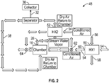
FIG. 2 is a schematic illustration of a multi-waste processor including a thermal control assembly operating in a vapor condensation mode; -
FIG. 3 is a schematic illustration of a multi-waste processor including a thermal control assembly operating in a chamber cooling mode; -
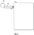
FIG. 4 is a schematic illustration of an embodiment of a liquid waste inlet arrangement to the processing chamber; and -
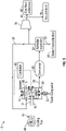
FIG. 5 is a schematic illustration of another embodiment of a multi-waste processor. - A detailed description of one or more embodiments of the disclosed apparatus and method are presented herein by way of exemplification and not limitation with reference to the Figures.
- Illustrated in
FIG. 1 is a schematic view of an embodiment of amulti-waste processor 10. Themulti-waste processor 10 is utilized to process bothliquid waste 12, such as urine, and othersolid waste 14, such as plastic, feces, and other trash, resulting in a considerable savings in weight and volume relative to typical systems, which is of utmost importance in an environment such as a space station. - The
liquid waste 12 and thesolid waste 14 are input into aprocessing chamber 16. Theliquid waste 12 andsolid waste 14 may be from a variety of sources, such as a universal waste management system (UWMS), also known as a "space toilet" or a urine processing assembly (UPA), which would provide feces, brine and/or urine to theprocessing chamber 16. Theprocessing chamber 16 includes one ormore heaters 18, and apiston 20 located inside theprocessing chamber 16 utilizing, for example, ascrew drive 22 or alternatively a linear actuator connected to thepiston 20 to drive movement of thepiston 20 in theprocessing chamber 16. In some embodiments, aheater 18 of the one ormore heaters 18 is located in thepiston 20. Once theliquid waste 12 and thesolid waste 14 are placed in theprocessing chamber 16, the pressure inside theprocessing chamber 16 is lowered by removing much of the air from theprocessing chamber 16 by use of, for example, avacuum pump 24 connected to theprocessing chamber 16. Lowering the pressure reduces the boiling point of the water content of the waste and facilitates the extraction of water from the waste. - The one or
more heaters 18 are activated thus evaporating, or in some instances boiling, theliquid waste 12 and producinggas effluent 26 which is directed from theprocessing chamber 16 to acondenser 28. In some embodiments, the one ormore heaters 18 are operated via solid state relays for fast switching between on/off, and are controlled by a proportional-integral-derivative (PID)controller 66 operably connected to the one ormore heaters 18 to reduce power usage by the one ormore heaters 18 while still effectively processing waste in theprocessing chamber 16. In thecondenser 28,water 32 is condensed from the gas effluent forming a two-phase flow which then proceeds to aseparator 30. In some embodiments, amicroporous bag 68, liner, or the like with a temperature resistant fitting is located inside of theprocessing chamber 16 when the input is mostlyliquid waste 12, for example. The fitting is closed to contain thesolid waste 14 portion, and during the heating and compression, theliquid waste 12 is removed from thebag 68 through the micropores, while the solid waste remains in thebag 68. Alternatively, such as shown inFIG. 4 , theliquid waste 12 may be loaded into theprocessing chamber 16 without such a bag, via one ormore input hoses 70 andinput pumps 72. Theprocessing chamber 16 is provided with aninput valve 74 to prevent undesired flow of theliquid waste 12 from theprocessing chamber 16 - At the
separator 30,water 32 is separated from thegas effluent 26. In some embodiments, the separator utilizes one or more of a condensing heat exchanger, rotor, membrane, adsorbent or the like to separate thewater 32 from thegas effluent 26. Thewater 32 is directed from theseparator 30 to awater collector 36, while gas byproducts from theseparator 30 are returned to theprocessing chamber 16 via arecirculation line 38. This process is repeated until a predefined amount or percentage of thewater 32 content is removed from thewaste 12/14 and collected in thewater collector 36. In some embodiments, greater than 90% of the water content is removed. To ensure thorough processing of theliquid waste 12 and thesolid waste 14, thepiston 20 is actuated to keep theheaters 18 in close contact with thewaste 12/14, and to compress thesolid waste 14 in theprocessing chamber 16. In some embodiments, thescrew drive 22 includes one or more features, for example a thread shape or locking mechanism, which prevents theliquid waste 12 and thesolid waste 14 in theprocessing chamber 16 from moving thepiston 20 from its selected position. - In some embodiments, the one or
more heaters 18 not only evaporate theliquid waste 12, but also soften or melt components of thesolid waste 14, for example, plastics, to improve compaction of thesolid waste 14. In some embodiments, thesolid waste 14 is compacted by greater than 80%. Once the heating process is completed, theprocessing chamber 16 may be cooled by, for example, a coolingairflow 44 from afan 46. - In other embodiments, as illustrated in
FIG. 2 andFIG. 3 , themulti-waste processor 10 includes athermal control assembly 48. Thethermal control assembly 48 includes afirst heat exchanger 50 and asecond heat exchanger 52 and is configured to operate in a condensing mode illustrated inFIG. 2 and a chamber cooling mode illustrated inFIG. 3 . First, in condensing mode as shown inFIG. 2 , thefirst heat exchanger 50 conditions anairflow 54 input to thefirst heat exchanger 50 by thermal energy exchange with acoolant flow 56 input into thefirst heat exchanger 50. Thecoolant flow 56 is output from thefirst heat exchanger 50 at acoolant outlet 58, while the conditionedairflow 54 is output from thefirst heat exchanger 50 at anair outlet 60. Thecoolant flow 56 may be a liquid, gas or other. The conditionedairflow 54 is then directed to thesecond heat exchanger 52 via afirst valve 62. As described above regardingFIG. 1 , theprocessing chamber 16outputs gas effluent 26. Thisgas effluent 26 is directed to thesecond heat exchanger 52 where thermal energy is exchanged with the conditionedairflow 54, thus condensingwater 32 from thegas effluent 26. Thewater 32 is condensed from the gas effluent forming a two-phase flow which then proceeds to theseparator 30. Thewater 32 is directed from theseparator 30 to thewater collector 36, while gas byproducts from theseparator 30 are returned to theprocessing chamber 16 via therecirculation line 38. After passing through thesecond heat exchanger 52, the conditionedairflow 54 is output viasecond valve 64. In some embodiments, only a single heat exchanger is utilized, and thecoolant flow 56 is applied directly to thecondenser 28 and/or theprocessing chamber 16. Referring now toFIG. 3 , via operation of thefirst valve 62 and thesecond valve 64, thethermal control assembly 48 may be configured to operate in the chamber cooling mode to cool theprocessing chamber 16. In chamber cooling mode, thefirst valve 62 directs the conditionedairflow 54 to theprocessing chamber 16, where the conditionedairflow 54 cools theprocessing chamber 16. The conditionedairflow 4 is output from theprocessing chamber 16 via thesecond valve 64. - When the desired amount of
water 32 is removed from thewaste 12/14 and recovered at thewater collector 36, and/or the desired degree of compaction of thesolid waste 14 is achieved and/or thesolid waste 14 is sterilized, the process is stopped. Thedry gas 40 is directed to agas collector 42 for venting via a vent, and/or reuse. In some embodiments, thedry gas 40 is passed through a catalytic oxidation interphase and/or a sorbent bed to process thedry gas 40 to allow for its venting back into a human habitable cabin or environment. The solid byproducts of themulti-waste processor 10 are geometrically stable and in some embodiments sterile, facilitating their handling and storage. In other embodiments where thesolid waste 14 is not heated sufficiently for sterilization, the solid byproducts may be placed, for example, in Ag-containing bags to facilitate safe handling. The solid byproducts may be reused as, for example, a radiation insulation material, a construction block or an energy source. In some embodiments, thewater 32 collected at thewater collector 36 may be further processed at, for example, a water processing system so that thewater 32 may be recycled for further use. - In another embodiment, such as illustrated in
FIG. 5 , themulti-waste processor 10 includes acompressor 76 and anaccumulator 78 in order to contain the effluents in the off nominal event such that the venting capabilities are disabled or unavailable while themulti-waste processor 10 is still continuing to process the waste contents. In such configurations, thedry gas 40 is compressed at thecompressor 76 and then routed to and stored at theaccumulator 78 until such time as it can be vented. Further, thecompressor 76 may be utilized to lower the pressure in theprocessing chamber 16, in addition to or in place of thevacuum pump 24. - The term "about" is intended to include the degree of error associated with measurement of the particular quantity based upon the equipment available at the time of filing the application.
- The terminology used herein is for the purpose of describing particular embodiments only and is not intended to be limiting of the present disclosure. As used herein, the singular forms "a", "an" and "the" are intended to include the plural forms as well, unless the context clearly indicates otherwise. It will be further understood that the terms "comprises" and/or "comprising," when used in this specification, specify the presence of stated features, integers, steps, operations, elements, and/or components, but do not preclude the presence or addition of one or more other features, integers, steps, operations, element components, and/or groups thereof.
- While the present disclosure has been described with reference to an exemplary embodiment or embodiments, it will be understood by those skilled in the art that various changes may be made without departing from the scope of the invention as defined by the claims. In addition, many modifications may be made to adapt a particular situation or material to the teachings of the present disclosure without departing from the scope of the claims. Therefore, it is intended that the present disclosure not be limited to the particular embodiment disclosed as the best mode contemplated for carrying out this present disclosure, but that the present disclosure will include all embodiments falling within the scope of the claims.
Claims (15)
- A multi-waste processing system, comprising:a processing chamber (16), the processing chamber including one or more heaters (18) and a piston (20), the processing chamber configured to evaporate liquid waste and compact solid waste input;a condenser (28) operably connected to the processing chamber, the condenser configured to condense water from the evaporated liquid waste output from the processing chamber; anda gas and water separator (30) operably connected to the condenser, the gas and water separator configured to separate water from the evaporated liquid waste output from the processing chamber; anda recirculation pathway (38) connecting the gas and water separator to the processing chamber to recirculate gas from the gas and water separator to the processing chamber;wherein the piston is actuated to keep the one or more heaters in close proximity to the solid waste and the liquid waste in the processing chamber.
- The multi-waste processing system of claim 1, further comprising a water collector (36) operably connected to the gas and water separator
- The multi-waste processing system of claim 1 or 2, further comprising a vacuum pump (24) operably connected to the processing chamber to reduce a pressure inside the processing chamber thereby reducing a boiling point of the liquid waste.
- The multi-waste processing system of any preceding claim, wherein the one or more heaters are configured to sterilize the compacted solid waste, and optionally wherein the processing chamber is configured to produce geometrically stable compacted solid waste.
- The multi-waste processing system of any preceding claim, wherein the piston is driven by one of a linear actuator or a screw drive.
- The multi-waste processing system of any preceding claim, further comprising a vent to dispose of or collect processed gas.
- The multi-waste processing system of any preceding claim, further comprising a catalytic oxidation reactor thermally integrated with the processing chamber.
- The multi-waste processing system of any preceding claim, further comprising:
a compressor (76) configured to compress processed gas; and - The multi-waste processing system of any preceding claim, wherein a heater of the one or more heaters is disposed in the piston.
- A method of multi-waste processing, comprising:inputting a volume of solid waste and a volume of liquid waste into a processing chamber (16);heating the processing chamber via one or more heaters (18) to evaporate the liquid waste therein;outputting the evaporated liquid waste in gas phase to a gas and water separator (30);condensing water from the evaporated liquid waste in gas phase at the condenser; andseparating water from gas at the separator; anddirecting gaseous products of the gas and water separator to the processing chamber via a recirculation line (38).
- The method of claim 10, further comprising compacting the solid waste at the processing chamber via actuation of a piston (20) at the processing chamber, and optionally wherein the compacted solid waste is geometrically stable, and/or wherein the solid waste is compacted greater than 80%.
- The method of claim 10 or 11, further comprising collecting the condensed water at a water collector.
- The method of claim 10, 11 or 12, further comprising reducing a pressure inside the processing chamber thereby reducing a boiling point of the liquid waste.
- The method of any of claims claim 10 to 13, further comprising disposing of a processed gas via a vent.
- The method of any of claims 10 to 14, further comprising treatment of the gas via catalytic oxidation in a reactor that is thermally integrated with the processing chamber; and/or further comprising:compressing processed gas at a compressor (76); andstoring the compressed processed gas at an accumulator (78).
Applications Claiming Priority (1)
| Application Number | Priority Date | Filing Date | Title |
|---|---|---|---|
| US17/226,381 US12179243B2 (en) | 2021-04-09 | 2021-04-09 | Multi waste processor |
Publications (1)
| Publication Number | Publication Date |
|---|---|
| EP4070875A1 true EP4070875A1 (en) | 2022-10-12 |
Family
ID=81748902
Family Applications (1)
| Application Number | Title | Priority Date | Filing Date |
|---|---|---|---|
| EP22166827.0A Pending EP4070875A1 (en) | 2021-04-09 | 2022-04-05 | Multi waste processor |
Country Status (3)
| Country | Link |
|---|---|
| US (1) | US12179243B2 (en) |
| EP (1) | EP4070875A1 (en) |
| JP (1) | JP7781692B2 (en) |
Citations (4)
| Publication number | Priority date | Publication date | Assignee | Title |
|---|---|---|---|---|
| US20020185016A1 (en) * | 2001-06-07 | 2002-12-12 | Claus Hoffjann | Apparatus for compacting and draining mixed waste in passenger transport vehicles |
| US20180354218A1 (en) * | 2017-06-09 | 2018-12-13 | Hamilton Sundstrand Corporation | Outer space waste compaction |
| US20200198991A1 (en) * | 2016-09-16 | 2020-06-25 | Paragon Space Development Corporation | Systems and methods for recovery of purified water and concentrated brine |
| CN111804712A (en) * | 2019-11-29 | 2020-10-23 | 深圳市康灵盾智能厨具设备有限公司 | A kitchen waste disposer |
Family Cites Families (18)
| Publication number | Priority date | Publication date | Assignee | Title |
|---|---|---|---|---|
| US3947327A (en) * | 1971-07-22 | 1976-03-30 | Hanover Research Corporation | Process and apparatus for recovering clean water from aqueous wastes |
| JPS6274806A (en) * | 1985-09-27 | 1987-04-06 | 株式会社日立製作所 | Kitchen waste processing equipment |
| US4745691A (en) * | 1987-03-20 | 1988-05-24 | Systems Engineering And Manufacturing Corp. | Means and methods for drying sludge |
| US5273719A (en) | 1988-05-10 | 1993-12-28 | Japanic Corporation | Urine treating device |
| JPH06183507A (en) * | 1992-01-16 | 1994-07-05 | Sekisui Chem Co Ltd | Disposal method and device for household refuse |
| JPH0970576A (en) * | 1995-09-04 | 1997-03-18 | Sharp Corp | Garbage processing equipment |
| JPH09314093A (en) * | 1996-06-04 | 1997-12-09 | Matsushita Electric Ind Co Ltd | Waste plastic volume reduction device and waste plastic volume reduction processing method |
| JPH10216673A (en) * | 1997-02-06 | 1998-08-18 | Jidosha Buhin Kogyo Co Ltd | Garbage drying equipment |
| RU2127627C1 (en) | 1998-07-21 | 1999-03-20 | Открытое акционерное общество "Научно-исследовательский и конструкторский институт химического машиностроения" | System and vacuum centrifugal distiller for regeneration of water from urine on spacecraft board |
| JP2004349518A (en) | 2003-05-23 | 2004-12-09 | Hitachi Kokusai Electric Inc | Semiconductor manufacturing equipment |
| US7024800B2 (en) * | 2004-07-19 | 2006-04-11 | Earthrenew, Inc. | Process and system for drying and heat treating materials |
| JP2006110600A (en) | 2004-10-15 | 2006-04-27 | Sun-Wa Tescom Corp | Waste compression volume reduction machine and waste compression volume reduction method |
| DE102010021742A1 (en) * | 2010-05-20 | 2011-11-24 | Ralf Schneider Holding Gmbh | Device for drying bulk material in at least one storage container |
| US20120055777A1 (en) | 2010-09-03 | 2012-03-08 | Liquidbreaker Llc. | Distillation Urine Recycling Systems and Methods |
| WO2014153007A1 (en) * | 2013-03-14 | 2014-09-25 | Revive Electronics, LLC | Methods and apparatuses for drying electronic devices |
| KR20170116086A (en) * | 2015-02-12 | 2017-10-18 | 뉴웨이 엠에스더블유 아이피 홀딩 엘엘피 | New methods and apparatus for converting undifferentiated municipal solid waste into geopolymer pellets / briquettes and geopolymer brick / sidewall blocks |
| BE1025113B1 (en) * | 2017-04-04 | 2018-10-31 | Organic Waste Systems, Verkort O.W.S. Naamloze Vennootschap | Device for separating a product into a liquid fraction and into a non-liquid fraction |
| US10653280B2 (en) | 2018-01-16 | 2020-05-19 | Hamilton Sundstrand Corporation | Method and apparatus for processing of fecal waste |
-
2021
- 2021-04-09 US US17/226,381 patent/US12179243B2/en active Active
-
2022
- 2022-03-30 JP JP2022054822A patent/JP7781692B2/en active Active
- 2022-04-05 EP EP22166827.0A patent/EP4070875A1/en active Pending
Patent Citations (4)
| Publication number | Priority date | Publication date | Assignee | Title |
|---|---|---|---|---|
| US20020185016A1 (en) * | 2001-06-07 | 2002-12-12 | Claus Hoffjann | Apparatus for compacting and draining mixed waste in passenger transport vehicles |
| US20200198991A1 (en) * | 2016-09-16 | 2020-06-25 | Paragon Space Development Corporation | Systems and methods for recovery of purified water and concentrated brine |
| US20180354218A1 (en) * | 2017-06-09 | 2018-12-13 | Hamilton Sundstrand Corporation | Outer space waste compaction |
| CN111804712A (en) * | 2019-11-29 | 2020-10-23 | 深圳市康灵盾智能厨具设备有限公司 | A kitchen waste disposer |
Also Published As
| Publication number | Publication date |
|---|---|
| US12179243B2 (en) | 2024-12-31 |
| JP7781692B2 (en) | 2025-12-08 |
| US20220324002A1 (en) | 2022-10-13 |
| JP2022161848A (en) | 2022-10-21 |
Similar Documents
| Publication | Publication Date | Title |
|---|---|---|
| US6258215B1 (en) | System and a rotary vacuum distiller for water recovery from aqueous solutions, preferably from urine aboard spacecraft | |
| KR102443681B1 (en) | Devices for treating medical waste and methods of their use | |
| US3248305A (en) | Fresh water recovery system | |
| US20210268401A1 (en) | Apparatus and method for extracting oil from plant material | |
| US3989461A (en) | Apparatus for use, recovery, reconstitution, and recyclization of sterilant gas mixture | |
| GB2040426A (en) | Environmental protection refrigerant disposal and charging system | |
| JPH06269605A (en) | Method and device for recovery of multi-component vapor mixture | |
| JP7042411B2 (en) | Steam generation system | |
| US8518252B1 (en) | System for field intravenous fluid reconstruction | |
| TW550367B (en) | Method and apparatus for producing a purified liquid | |
| US12179243B2 (en) | Multi waste processor | |
| US8246789B2 (en) | Hydrous matter treatment system | |
| JPH07241545A (en) | Kitchen waste processing equipment | |
| RU83415U1 (en) | MEDICAL WASTE DISPOSAL | |
| Turner et al. | Generation 2 heat melt compactor development | |
| RU2650068C9 (en) | Solid medical wastes thermal disinfection system | |
| Wetzel et al. | Heat melt compactor test unit | |
| WO2010004302A1 (en) | Energy absorption and release devices and systems | |
| JP2002017825A (en) | Steam sterilizing device | |
| JP2004313918A (en) | Vacuum sludge drying method and equipment | |
| Klopotic et al. | Design of a Trash Compaction & Processing System (TCPS) for Waste Management and Logistics Reduction in Long Duration Spaceflight | |
| CN120285259A (en) | A dry heat disinfection device for medical waste | |
| WO2005051559A1 (en) | Device and method for removing mercury from residues | |
| JPH08290004A (en) | Solution vacuum distillation device | |
| CN113683243A (en) | Small sewage recycling and treatment device |
Legal Events
| Date | Code | Title | Description |
|---|---|---|---|
| PUAI | Public reference made under article 153(3) epc to a published international application that has entered the european phase |
Free format text: ORIGINAL CODE: 0009012 |
|
| STAA | Information on the status of an ep patent application or granted ep patent |
Free format text: STATUS: THE APPLICATION HAS BEEN PUBLISHED |
|
| AK | Designated contracting states |
Kind code of ref document: A1 Designated state(s): AL AT BE BG CH CY CZ DE DK EE ES FI FR GB GR HR HU IE IS IT LI LT LU LV MC MK MT NL NO PL PT RO RS SE SI SK SM TR |
|
| STAA | Information on the status of an ep patent application or granted ep patent |
Free format text: STATUS: REQUEST FOR EXAMINATION WAS MADE |
|
| 17P | Request for examination filed |
Effective date: 20230412 |
|
| RBV | Designated contracting states (corrected) |
Designated state(s): AL AT BE BG CH CY CZ DE DK EE ES FI FR GB GR HR HU IE IS IT LI LT LU LV MC MK MT NL NO PL PT RO RS SE SI SK SM TR |