EP4070733A1 - Abnormal physical condition determination system, abnormal physical condition determination method, and computer program - Google Patents
Abnormal physical condition determination system, abnormal physical condition determination method, and computer program Download PDFInfo
- Publication number
- EP4070733A1 EP4070733A1 EP19955334.8A EP19955334A EP4070733A1 EP 4070733 A1 EP4070733 A1 EP 4070733A1 EP 19955334 A EP19955334 A EP 19955334A EP 4070733 A1 EP4070733 A1 EP 4070733A1
- Authority
- EP
- European Patent Office
- Prior art keywords
- physical condition
- abnormal physical
- condition determination
- unit
- target person
- Prior art date
- Legal status (The legal status is an assumption and is not a legal conclusion. Google has not performed a legal analysis and makes no representation as to the accuracy of the status listed.)
- Pending
Links
- 230000002159 abnormal effect Effects 0.000 title claims abstract description 211
- 238000000034 method Methods 0.000 title claims description 21
- 238000004590 computer program Methods 0.000 title claims description 19
- 238000009825 accumulation Methods 0.000 claims abstract description 25
- 238000004364 calculation method Methods 0.000 claims abstract description 23
- 238000000605 extraction Methods 0.000 claims abstract description 20
- 239000000284 extract Substances 0.000 claims abstract description 7
- 201000003152 motion sickness Diseases 0.000 claims description 54
- 210000001747 pupil Anatomy 0.000 claims description 10
- 238000010586 diagram Methods 0.000 description 24
- 230000001133 acceleration Effects 0.000 description 18
- 238000001514 detection method Methods 0.000 description 14
- 230000000694 effects Effects 0.000 description 9
- 230000006399 behavior Effects 0.000 description 7
- 230000005856 abnormality Effects 0.000 description 5
- 208000002173 dizziness Diseases 0.000 description 5
- 238000005516 engineering process Methods 0.000 description 5
- 238000003384 imaging method Methods 0.000 description 4
- 230000035622 drinking Effects 0.000 description 3
- 230000006870 function Effects 0.000 description 3
- 230000007613 environmental effect Effects 0.000 description 2
- 239000006187 pill Substances 0.000 description 2
- 208000012886 Vertigo Diseases 0.000 description 1
- 238000004378 air conditioning Methods 0.000 description 1
- 238000004458 analytical method Methods 0.000 description 1
- 230000008030 elimination Effects 0.000 description 1
- 238000003379 elimination reaction Methods 0.000 description 1
- 210000000887 face Anatomy 0.000 description 1
- 230000001815 facial effect Effects 0.000 description 1
- 239000011521 glass Substances 0.000 description 1
- 230000007774 longterm Effects 0.000 description 1
- 206010025482 malaise Diseases 0.000 description 1
- 239000007787 solid Substances 0.000 description 1
- 231100000889 vertigo Toxicity 0.000 description 1
Images


Classifications
-
- G—PHYSICS
- G16—INFORMATION AND COMMUNICATION TECHNOLOGY [ICT] SPECIALLY ADAPTED FOR SPECIFIC APPLICATION FIELDS
- G16H—HEALTHCARE INFORMATICS, i.e. INFORMATION AND COMMUNICATION TECHNOLOGY [ICT] SPECIALLY ADAPTED FOR THE HANDLING OR PROCESSING OF MEDICAL OR HEALTHCARE DATA
- G16H30/00—ICT specially adapted for the handling or processing of medical images
- G16H30/40—ICT specially adapted for the handling or processing of medical images for processing medical images, e.g. editing
-
- G—PHYSICS
- G06—COMPUTING; CALCULATING OR COUNTING
- G06V—IMAGE OR VIDEO RECOGNITION OR UNDERSTANDING
- G06V20/00—Scenes; Scene-specific elements
- G06V20/50—Context or environment of the image
- G06V20/59—Context or environment of the image inside of a vehicle, e.g. relating to seat occupancy, driver state or inner lighting conditions
- G06V20/597—Recognising the driver's state or behaviour, e.g. attention or drowsiness
-
- A—HUMAN NECESSITIES
- A61—MEDICAL OR VETERINARY SCIENCE; HYGIENE
- A61B—DIAGNOSIS; SURGERY; IDENTIFICATION
- A61B5/00—Measuring for diagnostic purposes; Identification of persons
- A61B5/0059—Measuring for diagnostic purposes; Identification of persons using light, e.g. diagnosis by transillumination, diascopy, fluorescence
- A61B5/0077—Devices for viewing the surface of the body, e.g. camera, magnifying lens
-
- A—HUMAN NECESSITIES
- A61—MEDICAL OR VETERINARY SCIENCE; HYGIENE
- A61B—DIAGNOSIS; SURGERY; IDENTIFICATION
- A61B5/00—Measuring for diagnostic purposes; Identification of persons
- A61B5/103—Detecting, measuring or recording devices for testing the shape, pattern, colour, size or movement of the body or parts thereof, for diagnostic purposes
- A61B5/11—Measuring movement of the entire body or parts thereof, e.g. head or hand tremor, mobility of a limb
- A61B5/1126—Measuring movement of the entire body or parts thereof, e.g. head or hand tremor, mobility of a limb using a particular sensing technique
- A61B5/1128—Measuring movement of the entire body or parts thereof, e.g. head or hand tremor, mobility of a limb using a particular sensing technique using image analysis
-
- A—HUMAN NECESSITIES
- A61—MEDICAL OR VETERINARY SCIENCE; HYGIENE
- A61B—DIAGNOSIS; SURGERY; IDENTIFICATION
- A61B5/00—Measuring for diagnostic purposes; Identification of persons
- A61B5/16—Devices for psychotechnics; Testing reaction times ; Devices for evaluating the psychological state
- A61B5/163—Devices for psychotechnics; Testing reaction times ; Devices for evaluating the psychological state by tracking eye movement, gaze, or pupil change
-
- A—HUMAN NECESSITIES
- A61—MEDICAL OR VETERINARY SCIENCE; HYGIENE
- A61B—DIAGNOSIS; SURGERY; IDENTIFICATION
- A61B5/00—Measuring for diagnostic purposes; Identification of persons
- A61B5/16—Devices for psychotechnics; Testing reaction times ; Devices for evaluating the psychological state
- A61B5/18—Devices for psychotechnics; Testing reaction times ; Devices for evaluating the psychological state for vehicle drivers or machine operators
-
- A—HUMAN NECESSITIES
- A61—MEDICAL OR VETERINARY SCIENCE; HYGIENE
- A61B—DIAGNOSIS; SURGERY; IDENTIFICATION
- A61B5/00—Measuring for diagnostic purposes; Identification of persons
- A61B5/68—Arrangements of detecting, measuring or recording means, e.g. sensors, in relation to patient
- A61B5/6887—Arrangements of detecting, measuring or recording means, e.g. sensors, in relation to patient mounted on external non-worn devices, e.g. non-medical devices
- A61B5/6893—Cars
-
- B—PERFORMING OPERATIONS; TRANSPORTING
- B60—VEHICLES IN GENERAL
- B60W—CONJOINT CONTROL OF VEHICLE SUB-UNITS OF DIFFERENT TYPE OR DIFFERENT FUNCTION; CONTROL SYSTEMS SPECIALLY ADAPTED FOR HYBRID VEHICLES; ROAD VEHICLE DRIVE CONTROL SYSTEMS FOR PURPOSES NOT RELATED TO THE CONTROL OF A PARTICULAR SUB-UNIT
- B60W40/00—Estimation or calculation of non-directly measurable driving parameters for road vehicle drive control systems not related to the control of a particular sub unit, e.g. by using mathematical models
- B60W40/08—Estimation or calculation of non-directly measurable driving parameters for road vehicle drive control systems not related to the control of a particular sub unit, e.g. by using mathematical models related to drivers or passengers
-
- F—MECHANICAL ENGINEERING; LIGHTING; HEATING; WEAPONS; BLASTING
- F16—ENGINEERING ELEMENTS AND UNITS; GENERAL MEASURES FOR PRODUCING AND MAINTAINING EFFECTIVE FUNCTIONING OF MACHINES OR INSTALLATIONS; THERMAL INSULATION IN GENERAL
- F16C—SHAFTS; FLEXIBLE SHAFTS; ELEMENTS OR CRANKSHAFT MECHANISMS; ROTARY BODIES OTHER THAN GEARING ELEMENTS; BEARINGS
- F16C32/00—Bearings not otherwise provided for
- F16C32/04—Bearings not otherwise provided for using magnetic or electric supporting means
- F16C32/0406—Magnetic bearings
- F16C32/044—Active magnetic bearings
- F16C32/0459—Details of the magnetic circuit
- F16C32/0461—Details of the magnetic circuit of stationary parts of the magnetic circuit
- F16C32/0465—Details of the magnetic circuit of stationary parts of the magnetic circuit with permanent magnets provided in the magnetic circuit of the electromagnets
-
- F—MECHANICAL ENGINEERING; LIGHTING; HEATING; WEAPONS; BLASTING
- F25—REFRIGERATION OR COOLING; COMBINED HEATING AND REFRIGERATION SYSTEMS; HEAT PUMP SYSTEMS; MANUFACTURE OR STORAGE OF ICE; LIQUEFACTION SOLIDIFICATION OF GASES
- F25B—REFRIGERATION MACHINES, PLANTS OR SYSTEMS; COMBINED HEATING AND REFRIGERATION SYSTEMS; HEAT PUMP SYSTEMS
- F25B31/00—Compressor arrangements
- F25B31/02—Compressor arrangements of motor-compressor units
- F25B31/026—Compressor arrangements of motor-compressor units with compressor of rotary type
-
- G—PHYSICS
- G06—COMPUTING; CALCULATING OR COUNTING
- G06T—IMAGE DATA PROCESSING OR GENERATION, IN GENERAL
- G06T7/00—Image analysis
- G06T7/70—Determining position or orientation of objects or cameras
- G06T7/73—Determining position or orientation of objects or cameras using feature-based methods
-
- G—PHYSICS
- G06—COMPUTING; CALCULATING OR COUNTING
- G06V—IMAGE OR VIDEO RECOGNITION OR UNDERSTANDING
- G06V10/00—Arrangements for image or video recognition or understanding
- G06V10/40—Extraction of image or video features
- G06V10/62—Extraction of image or video features relating to a temporal dimension, e.g. time-based feature extraction; Pattern tracking
-
- G—PHYSICS
- G06—COMPUTING; CALCULATING OR COUNTING
- G06V—IMAGE OR VIDEO RECOGNITION OR UNDERSTANDING
- G06V10/00—Arrangements for image or video recognition or understanding
- G06V10/70—Arrangements for image or video recognition or understanding using pattern recognition or machine learning
- G06V10/74—Image or video pattern matching; Proximity measures in feature spaces
-
- G—PHYSICS
- G06—COMPUTING; CALCULATING OR COUNTING
- G06V—IMAGE OR VIDEO RECOGNITION OR UNDERSTANDING
- G06V40/00—Recognition of biometric, human-related or animal-related patterns in image or video data
- G06V40/10—Human or animal bodies, e.g. vehicle occupants or pedestrians; Body parts, e.g. hands
- G06V40/16—Human faces, e.g. facial parts, sketches or expressions
- G06V40/168—Feature extraction; Face representation
- G06V40/171—Local features and components; Facial parts ; Occluding parts, e.g. glasses; Geometrical relationships
-
- G—PHYSICS
- G16—INFORMATION AND COMMUNICATION TECHNOLOGY [ICT] SPECIALLY ADAPTED FOR SPECIFIC APPLICATION FIELDS
- G16H—HEALTHCARE INFORMATICS, i.e. INFORMATION AND COMMUNICATION TECHNOLOGY [ICT] SPECIALLY ADAPTED FOR THE HANDLING OR PROCESSING OF MEDICAL OR HEALTHCARE DATA
- G16H40/00—ICT specially adapted for the management or administration of healthcare resources or facilities; ICT specially adapted for the management or operation of medical equipment or devices
- G16H40/60—ICT specially adapted for the management or administration of healthcare resources or facilities; ICT specially adapted for the management or operation of medical equipment or devices for the operation of medical equipment or devices
- G16H40/67—ICT specially adapted for the management or administration of healthcare resources or facilities; ICT specially adapted for the management or operation of medical equipment or devices for the operation of medical equipment or devices for remote operation
-
- G—PHYSICS
- G16—INFORMATION AND COMMUNICATION TECHNOLOGY [ICT] SPECIALLY ADAPTED FOR SPECIFIC APPLICATION FIELDS
- G16H—HEALTHCARE INFORMATICS, i.e. INFORMATION AND COMMUNICATION TECHNOLOGY [ICT] SPECIALLY ADAPTED FOR THE HANDLING OR PROCESSING OF MEDICAL OR HEALTHCARE DATA
- G16H50/00—ICT specially adapted for medical diagnosis, medical simulation or medical data mining; ICT specially adapted for detecting, monitoring or modelling epidemics or pandemics
- G16H50/20—ICT specially adapted for medical diagnosis, medical simulation or medical data mining; ICT specially adapted for detecting, monitoring or modelling epidemics or pandemics for computer-aided diagnosis, e.g. based on medical expert systems
-
- G—PHYSICS
- G16—INFORMATION AND COMMUNICATION TECHNOLOGY [ICT] SPECIALLY ADAPTED FOR SPECIFIC APPLICATION FIELDS
- G16H—HEALTHCARE INFORMATICS, i.e. INFORMATION AND COMMUNICATION TECHNOLOGY [ICT] SPECIALLY ADAPTED FOR THE HANDLING OR PROCESSING OF MEDICAL OR HEALTHCARE DATA
- G16H50/00—ICT specially adapted for medical diagnosis, medical simulation or medical data mining; ICT specially adapted for detecting, monitoring or modelling epidemics or pandemics
- G16H50/30—ICT specially adapted for medical diagnosis, medical simulation or medical data mining; ICT specially adapted for detecting, monitoring or modelling epidemics or pandemics for calculating health indices; for individual health risk assessment
-
- H—ELECTRICITY
- H02—GENERATION; CONVERSION OR DISTRIBUTION OF ELECTRIC POWER
- H02K—DYNAMO-ELECTRIC MACHINES
- H02K7/00—Arrangements for handling mechanical energy structurally associated with dynamo-electric machines, e.g. structural association with mechanical driving motors or auxiliary dynamo-electric machines
- H02K7/08—Structural association with bearings
- H02K7/09—Structural association with bearings with magnetic bearings
-
- A—HUMAN NECESSITIES
- A61—MEDICAL OR VETERINARY SCIENCE; HYGIENE
- A61B—DIAGNOSIS; SURGERY; IDENTIFICATION
- A61B2576/00—Medical imaging apparatus involving image processing or analysis
- A61B2576/02—Medical imaging apparatus involving image processing or analysis specially adapted for a particular organ or body part
-
- B—PERFORMING OPERATIONS; TRANSPORTING
- B60—VEHICLES IN GENERAL
- B60W—CONJOINT CONTROL OF VEHICLE SUB-UNITS OF DIFFERENT TYPE OR DIFFERENT FUNCTION; CONTROL SYSTEMS SPECIALLY ADAPTED FOR HYBRID VEHICLES; ROAD VEHICLE DRIVE CONTROL SYSTEMS FOR PURPOSES NOT RELATED TO THE CONTROL OF A PARTICULAR SUB-UNIT
- B60W40/00—Estimation or calculation of non-directly measurable driving parameters for road vehicle drive control systems not related to the control of a particular sub unit, e.g. by using mathematical models
- B60W40/08—Estimation or calculation of non-directly measurable driving parameters for road vehicle drive control systems not related to the control of a particular sub unit, e.g. by using mathematical models related to drivers or passengers
- B60W2040/0872—Driver physiology
-
- B—PERFORMING OPERATIONS; TRANSPORTING
- B60—VEHICLES IN GENERAL
- B60W—CONJOINT CONTROL OF VEHICLE SUB-UNITS OF DIFFERENT TYPE OR DIFFERENT FUNCTION; CONTROL SYSTEMS SPECIALLY ADAPTED FOR HYBRID VEHICLES; ROAD VEHICLE DRIVE CONTROL SYSTEMS FOR PURPOSES NOT RELATED TO THE CONTROL OF A PARTICULAR SUB-UNIT
- B60W2420/00—Indexing codes relating to the type of sensors based on the principle of their operation
- B60W2420/40—Photo, light or radio wave sensitive means, e.g. infrared sensors
- B60W2420/403—Image sensing, e.g. optical camera
-
- B—PERFORMING OPERATIONS; TRANSPORTING
- B60—VEHICLES IN GENERAL
- B60W—CONJOINT CONTROL OF VEHICLE SUB-UNITS OF DIFFERENT TYPE OR DIFFERENT FUNCTION; CONTROL SYSTEMS SPECIALLY ADAPTED FOR HYBRID VEHICLES; ROAD VEHICLE DRIVE CONTROL SYSTEMS FOR PURPOSES NOT RELATED TO THE CONTROL OF A PARTICULAR SUB-UNIT
- B60W2540/00—Input parameters relating to occupants
- B60W2540/223—Posture, e.g. hand, foot, or seat position, turned or inclined
-
- B—PERFORMING OPERATIONS; TRANSPORTING
- B60—VEHICLES IN GENERAL
- B60W—CONJOINT CONTROL OF VEHICLE SUB-UNITS OF DIFFERENT TYPE OR DIFFERENT FUNCTION; CONTROL SYSTEMS SPECIALLY ADAPTED FOR HYBRID VEHICLES; ROAD VEHICLE DRIVE CONTROL SYSTEMS FOR PURPOSES NOT RELATED TO THE CONTROL OF A PARTICULAR SUB-UNIT
- B60W2540/00—Input parameters relating to occupants
- B60W2540/225—Direction of gaze
-
- B—PERFORMING OPERATIONS; TRANSPORTING
- B60—VEHICLES IN GENERAL
- B60W—CONJOINT CONTROL OF VEHICLE SUB-UNITS OF DIFFERENT TYPE OR DIFFERENT FUNCTION; CONTROL SYSTEMS SPECIALLY ADAPTED FOR HYBRID VEHICLES; ROAD VEHICLE DRIVE CONTROL SYSTEMS FOR PURPOSES NOT RELATED TO THE CONTROL OF A PARTICULAR SUB-UNIT
- B60W60/00—Drive control systems specially adapted for autonomous road vehicles
- B60W60/001—Planning or execution of driving tasks
- B60W60/0015—Planning or execution of driving tasks specially adapted for safety
- B60W60/0016—Planning or execution of driving tasks specially adapted for safety of the vehicle or its occupants
-
- G—PHYSICS
- G06—COMPUTING; CALCULATING OR COUNTING
- G06T—IMAGE DATA PROCESSING OR GENERATION, IN GENERAL
- G06T2207/00—Indexing scheme for image analysis or image enhancement
- G06T2207/30—Subject of image; Context of image processing
- G06T2207/30196—Human being; Person
- G06T2207/30201—Face
-
- G—PHYSICS
- G06—COMPUTING; CALCULATING OR COUNTING
- G06T—IMAGE DATA PROCESSING OR GENERATION, IN GENERAL
- G06T2207/00—Indexing scheme for image analysis or image enhancement
- G06T2207/30—Subject of image; Context of image processing
- G06T2207/30248—Vehicle exterior or interior
- G06T2207/30268—Vehicle interior
Definitions
- the present invention relates to an abnormal physical condition determination system, an abnormal physical condition determination method, and a computer program that determine an abnormal physical condition of a target person.
- Patent Literature 1 discloses a technique/technology of estimating a condition of a driver from a position of a face, a direction of the face, a gaze direction, and the like that are obtained by analyzing a face image.
- Patent Literature 2 discloses a technique/technology of detecting a face position from a face image and estimating the condition of the driver by using a degree of opening and closing of an eye, the gaze direction, the direction of the face, and the like.
- Patent Literature 3 discloses a technique/technology of detecting a feature point vector from a plurality of feature points extracted from image data on a face.
- the present invention has been made in view of the above problems, and it is an example object of the present invention is to provide an abnormal physical condition determination system, an abnormal physical condition determination method, and a computer program that are appropriately determine an abnormal physical condition of a target person.
- An abnormal physical condition determination system includes: an extraction unit that extracts a plurality of feature quantities indicating a condition of a target person from an image of the target person; an accumulation unit that accumulates the plurality of feature quantities as time series data; a calculation unit that calculates a relationship between each feature quantity from the plurality of feature quantities accumulated in the accumulation unit; and a determination unit that determines an abnormal physical condition of the target person on the basis of the relationship.
- An abnormal physical condition determination method includes: extracting a plurality of feature quantities indicating a condition of a target person from an image of the target person; accumulating the plurality of feature quantities as time series data; calculating a relationship between each feature quantity from the plurality of feature quantities accumulated in the accumulation unit; and determining an abnormal physical condition of the target person on the basis of the relationship.
- a computer program of the present invention operates a computer: to extract a plurality of feature quantities indicating a condition of a target person from an image of the target person; to accumulate the plurality of feature quantities as time series data; to calculate a relationship between each feature quantity from the plurality of feature quantities accumulated in the accumulation unit; and to determine an abnormal physical condition of the target person on the basis of the relationship.
- the abnormal physical condition determination system According to the abnormal physical condition determination system, the abnormal physical condition determination method, and the computer program in the respective aspects described above, it is possible to appropriately determine the abnormal condition of the target person.
- an abnormal physical condition determination system will be described with reference to FIG. 1 to FIG. 5 .
- the abnormal physical condition determination system is an apparatus that determines an abnormal physical condition of an occupant of a vehicle (specifically, a motion sickness).
- FIG. 1 is a block diagram illustrating the overall configuration of the abnormal physical condition determination system according to a first example embodiment.
- FIG. 2 is a block diagram illustrating an overall configuration of an abnormal physical condition determination system according to a modified example.
- an abnormal physical condition determination system 1 is installed in a vehicle 10 including a cabin camera 50.
- the abnormal physical condition determination system 1 includes, as functional blocks for realizing its functions, an image acquisition unit 101, a target detection unit 102, a feature extraction unit 103, a feature accumulation unit 104, a feature relationship calculation unit 105, and an abnormal physical condition determination unit 106.
- the image acquisition unit 101 is configured to obtain an image captured by the cabin camera 50 (specifically, an image of an occupant of the vehicle 10).
- the image obtained by the image acquisition unit 101 is configured to be outputted to the target detection unit 102.
- the target detection unit 102 is configured to detect a target person whose abnormal physical condition is determined, from the image obtained by the image acquisition unit 101.
- the target detection unit 102 detects, for example, an area in which the target person appears, (e.g., a face area of the target person, etc.) from the captured image.
- an area in which the target person appears e.g., a face area of the target person, etc.
- a detection result of the target detection unit 102 is configured to be outputted to the feature extraction unit 103.
- the feature extraction unit 103 is configured to extract feature quantities for determining the abnormal physical condition of the target person from the area detected by the target detection unit 102.
- the feature quantities extracted by the feature extraction unit 103 include, for example, feature quantities related to the position of a pupil of the occupant, the direction of a face, a gaze direction, the color of the face, the position of a face feature point, and a degree of opening of a lid.
- the feature extraction unit 103 extracts a plurality of types of feature quantities from the occupant.
- the feature quantities extracted by the feature extraction unit 103 are configured to be outputted to each of the feature accumulation unit 104 and the feature relationship calculation unit 105.
- the feature accumulation unit 104 is configured to accumulate the feature quantities extracted by the feature extraction unit 103, as time series data.
- the feature accumulation unit 104 accumulates the feature quantities, for example, in units of frames arranged in time series.
- the feature quantities accumulated in the feature accumulation unit 104 are configured to be appropriately outputted to the feature relationship calculation unit 105.
- the feature relationship calculation unit 105 is configured to calculate a relationship between each feature quantity (i.e., a relationship between different types of feature quantities), from time series data on a plurality of types of feature quantities. More specifically, the feature relationship calculation unit 105 calculates the relationship between each feature quantity, from the feature quantities extracted by the feature extraction unit 103 (in other words, current feature quantities) and the feature quantities read from the feature accumulation unit 104 (in other words, past feature quantities). The relationship between each feature quantity is calculated, for example, as a feature vector having a plurality of dimensions. The relationship between each feature quantity calculated by the feature relationship calculation unit 105 is configured to be outputted to the abnormal physical condition determination unit 106.
- the abnormal physical condition determination unit 106 determines the abnormal physical condition of the occupant on the basis of the relationship between each feature quantity calculated by the feature relationship calculation unit 105.
- the abnormal physical condition determination unit 106 determines, for example, whether or not the occupant is in an abnormal physical condition, or a degree of the abnormal physical condition of the occupant.
- the determination of the abnormal physical condition can be performed by setting a relevance between the abnormal physical condition and the relationship of feature quantities in advance. For example, a threshold for the feature vector may be set, and when the calculated feature vector exceeds the threshold, it may be determined that the occupant is in the abnormal physical condition.
- the abnormal physical condition determination unit 106 may be configured to learn the threshold associated with the determination. For example, the abnormal physical condition determination unit 106 may perform learning by using correct data or the like obtained by an input made by the occupant.
- the abnormal physical condition determination system 1 may be provided in an external server 20 that is outside the vehicle 10. That is, the abnormal physical condition determination system 1 may not necessarily be installed in the vehicle 10. Instead of all the components of the abnormal physical condition determination system 1, a part of the components of the abnormal physical condition determination system 1 may be provided in the external server 20.
- FIG. 3 is a block diagram illustrating the hardware configuration of the abnormal physical condition determination system according to the first example embodiment.
- the abnormal physical condition determination system 1 includes a CPU (Central Processing Unit) 11, a RAM (Random Access Memory) 12, a ROM (Read Only Memory) 13, and a storage apparatus 14.
- the abnormal physical condition determination system 1 may further include an input apparatus 15 and an output apparatus 16.
- the CPU 11, the RAM 12, the ROM 13, the storage apparatus 14, the input apparatus 15, and the output apparatus 16 are connected through a data bus 17.
- the CPU 11 reads a computer program.
- the CPU 11 is configured to read a computer program stored by at least one of the RAM 12, the ROM 13 and the storage apparatus 14.
- the CPU 11 may read a computer program stored by a computer readable recording medium by using a not-illustrated recording medium reading apparatus.
- the CPU 11 may obtain (i.e., read) a computer program from a not-illustrated apparatus that is located outside the physical condition determination system 1 through a network interface.
- the CPU 11 controls the RAM 12, the storage apparatus 14, the input apparatus 15, and the output apparatus 16 by executing the read computer program.
- a functional block for determining the abnormal physical condition is implemented in the CPU 11.
- the RAM 12 temporarily stores the computer program to be executed by the CPU 11.
- the RAM 12 temporarily stores the data that is temporarily used by the CPU 11 when the CPU 11 executes the computer program.
- the RAM 12 may be, for example, a D-RAM (Dynamic RAM).
- the ROM 13 stores the computer program to be executed by the CPU 11.
- the ROM 13 may otherwise store fixed data.
- the ROM 13 may be, for example, a P-ROM (Programmable ROM).
- the storage apparatus 14 stores the data that is stored for a long term by the abnormal physical condition determination system 1.
- the storage apparatus 14 may operate as a temporary storage apparatus of the CPU 11.
- the storage apparatus 14 may include, for example, at least one of a hard disk apparatus, a magneto-optical disk apparatus, an SSD (Solid State Drive), and a disk array apparatus.
- the input apparatus 15 is an apparatus that receives an input instruction from a user of the abnormal physical condition determination system 1.
- the input apparatus 15 may include, for example, at least one of a keyboard, a mouse, and a touch panel.
- the output apparatus 16 is an apparatus that outputs information about the abnormal physical condition determination system 1 to the outside.
- the output apparatus 16 may be a display apparatus (e.g., a display) that is configured to display the information about the abnormal physical condition determination system 1.
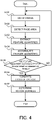
- FIG. 4 is a flowchart illustrating the flow of the operation of the abnormal physical condition determination system according to the first example embodiment.
- the image acquisition unit 101 obtains the image of the occupant captured by the cabin camera 50 (step S101). Then, the target detection unit 102 detects the face area from the image of the occupant (step S102). When the feature quantities are detected from other than the face area, another area corresponding to the feature quantities may be detected.
- the feature extraction unit 103 extracts the feature quantities from the face area (step S103). Then, the feature accumulation unit 104 accumulates (i.e., stores) the extracted feature quantities (step S104).
- the feature relationship calculation unit 105 determines whether or not the feature quantities are accumulated for a predetermined number of frames in the feature accumulation unit 104 (step S105).
- the " predetermined number of frames” is a value corresponding to an amount of feature quantities sufficient to calculate the relationship between each feature quantity, and an optimum value (e.g., the number of frames corresponding to 5 seconds) is set in advance.
- the process is performed from the step S101 again. That is, the process of extracting the feature quantities from the image of the occupant and accumulating them is repeated.
- the feature relationship calculation unit 105 calculates the relationship between each feature quantity (step S106). Then, the abnormal physical condition determination unit 106 determines the abnormal physical condition of the occupant (here, a motion sickness) on the basis of the calculated relationship between each feature quantity (step S107).
- the abnormal physical condition determination system 1 may start the operation, for example, when the vehicle 10 starts to run. Furthermore, it may start the operation at a timing after a lapse of a predetermined time (a time in which the abnormality supposedly begins to appear in the physical condition of the occupant) from the start of the running.
- a predetermined time may be arbitrarily set.
- the predetermined time may be set on the basis of a history information, wherein a time from the start of the running until the abnormality begins to appear in the physical condition of the occupant is stored as the history information. In this way, it is possible to reduce an unnecessary process in a period in which the occupant is not in an abnormal physical condition.
- the abnormal physical condition determination system 1 may start the operation at a timing at which the face of the occupant can be normally detected or at a timing at which the occupant gets in the vehicle. In this way, the face of the occupant can be tracked, and it is thus possible to prevent a situation in which the face of the occupant cannot be detected even though the occupant is in the abnormal physical condition.
- the abnormal physical condition determination system 1 may start the operation on the basis of a behavior information about the vehicle (e.g., at a timing at which a threshold of an acceleration sensor becomes greater than or equal to a predetermined threshold). In this way, it is possible to reduce an unnecessary process when the vehicle takes a behavior that hardly causes the abnormal physical condition.
- the abnormal physical condition determination system 1 ends the operation, for example, at a timing when the vehicle 10 stops running. Alternatively, it may end the operation on the basis of the behavior information about the vehicle (e.g., at a timing at which the threshold of the acceleration sensor is less than or equal to a predetermined threshold).
- FIG. 5 is a table illustrating a specific example of the feature vector.
- the feature extraction unit 103 extracts positions of the occupant's right and left eye pupils, a face direction angle (pan, tilt, and roll directions), and a gaze angle (horizontal and vertical directions) as the feature quantities.
- the feature relationship calculation unit 105 calculates the relationship between the above-described plurality of types of feature quantities, as a multi-dimensional feature vector.
- the feature relationship calculation unit 105 calculates an eight-dimensional feature vector including (1) a correlation between a face position and a right pupil position, (2) a correlation between the face position and a left pupil position, (3) a correlation between a face pan direction and a gaze horizontal direction, (4) a correlation between a face tilt direction and a gaze vertical direction, (5) a ratio in a moving velocity between a face gravity-center position and a right eye position, (6) a ratio in the moving velocity between the face gravity-center position and a left eye position, (7) a ratio in an angular velocity between the face pan direction and the gaze horizontal direction, and (8) a ratio in the angular velocity between the face tilt direction and the gaze vertical direction.
- the correlation is obtained by dividing the covariance of the face position and the right pupil by the product of a standard deviation of the face position and a standard deviation of the right pupil.
- each element of the feature vector may be appropriately weighted.
- the weight in this case may be determined in accordance with a face condition estimated from the image of the face area. Specifically, when the occupant wears glasses, the weight of the feature quantity related to the eyes may be reduced because the accuracy of the feature quantity obtained for the eyes is considered to be reduced.
- the feature vector does not need to be eight-dimensional, and may have dimensionality that is appropriately set.
- the abnormal physical condition determination unit 106 determines that the occupant is in the abnormal physical condition on the basis of the calculated relationship between each feature quantity. Specifically, when the correlation and the ratio calculated by the feature relationship calculation unit 105 are greater than or equal to a predetermined value, it is determined that the occupant is in the abnormal physical condition. Incidentally, in calculating the eight-dimensional feature vector including the above-described (1) to (8), it may be determined that the occupant is in the abnormal physical condition when any one or more correlations or ratios are greater than or equal to a predetermined value, or it may be determined that the occupant is in the abnormal physical condition when all the eight correlations and ratios are greater than or equal to respective predetermined values.
- the occupant feels vertigo, or dizziness in eye opening.
- the above-described (1) to (8) in the feature vector are calculated as the relationship between a pair of feature quantities that normally changes in the same manner. Therefore, according to the feature vector described above, it is possible to discriminate a situation in which the movements of the face and eyes do not correspond to each other due to dizziness, and it is possible to suitably determine the occurrence of the motion sickness.
- the feature vector described above is merely an example, and another relationship of feature quantities may be used.
- a pair of feature quantities for calculating their relationship may be determined in accordance with the type of the abnormal physical condition that is to be determined.
- the abnormal physical condition determination system 1 in the first example embodiment it is possible to determine the motion sickness of the occupant on the basis of the feature quantities extracted from the image of the occupant.
- the motion sickness is determined on the basis of the relationship between a plurality of feature quantities, rather than by directly utilizing the extracted feature quantities. Therefore, for example, it is possible to suppress an influence of environmental variations, such as individual differences and lighting conditions, and it is possible to determine the motion sickness with high accuracy.
- the feature quantities that are time series data are utilized, unlike the case where the feature quantities are extracted from only one image, a change per unit time in the feature quantities can also be considered. Therefore, it is possible to determine the motion sickness, more accurately.
- the above example embodiment describes an example of determining the motion sickness of the occupant of the vehicle 10, but the motion sickness of the occupant of a movable body other than the vehicle 10, such as, for example, a ship or an airplane, may be also determined.
- an abnormal physical condition other than the motion sickness may be determined. Specifically, a determination may be performed on dizziness that may occur in the use of a VR (Virtual Reality) apparatus (so-called VR sickness) or the like. If the feature quantity related to the face of the target person is utilized as in the example embodiment, it is possible to appropriately determine the abnormal physical condition that is especially accompanied by dizziness, but it can also be applied to the determination of another abnormal physical condition that is not accompanied by dizziness, by utilizing the relationship between appropriate feature quantities.
- the abnormal physical condition determination system 1 will be described with reference to FIG. 6 to FIG. 12 .
- the second example embodiment is partially different from the above-described first example embodiment only in the configuration and operation, and is substantially the same in the other parts. Therefore, the parts that differ from the first example embodiment will be described in detail below, and the other overlapping parts will be omitted as appropriate.
- FIG. 6 is a block diagram illustrating the overall configuration of the abnormal physical condition determination system according to the second example embodiment.
- FIG. 7 is a schematic diagram illustrating an interior configuration of a vehicle to which the abnormal physical condition determination system according to the second example embodiment is applied.
- the same components as those illustrated in FIG. 1 carry the same reference numerals.
- the abnormal physical condition determination system 1 includes a determination result output unit 107 in addition to the components of the abnormal physical condition determination system 1 according to the first example embodiment (see FIG. 1 ).
- the abnormal physical condition determination unit 106 may identify a cause of the abnormal physical condition of the occupant from the information indicating the behavior of the vehicle 10.
- the abnormal physical condition determination unit 106 may be configured to obtain the information indicating the behavior of the vehicle 10 from a not-illustrated sensor (e.g., an acceleration sensor or the like) provided in the vehicle 10.
- the abnormal physical condition determination unit 106 may identify the cause of the abnormal physical condition of the occupant from an analysis result of the image of the occupant, or the like.
- the abnormal physical condition determination unit 106 may be configured to extract the feature quantity that allows the cause of the abnormal physical condition to be determined, from an image or the like including a whole body of the occupant.
- a not-illustrated abnormal physical condition cause identification unit may identify the cause of the abnormal physical condition of the occupant.
- the abnormal physical condition determination unit 106 obtains an acceleration of the vehicle at the determined timing.
- the abnormal physical condition determination unit 106 compares the obtained acceleration with a threshold stored in advance (e.g., an acceleration that likely causes the abnormal physical condition), thereby to determine whether or not the abnormal physical condition of the occupant is due to the acceleration of the vehicle 10.
- the obtained acceleration may be an acceleration at a timing a predetermined period before the timing at which it is determined that the occupant is in the abnormal physical condition. Alternatively, it may be an acceleration in a predetermined period until the timing at which it is determined that the occupant is in the abnormal physical condition.
- At least one of a velocity, an angular velocity, an angular velocity in a yaw direction, an angular acceleration in the yaw direction, an angular velocity in a pitch direction, an angular acceleration in the pitch direction, an angular velocity in a roll direction, and an angular acceleration in the roll direction may be obtained.
- the cause may be identified on the basis of at least one of them or all of them.
- the abnormal physical condition determination unit 106 may identify the cause of the abnormal physical condition without comparing the detected acceleration or the like with the threshold. For example, with respect to the acceleration detected at the timing at which it is determined that the occupant is in the abnormal physical condition, it can be determined that the acceleration itself is the cause of the abnormal physical condition. Therefore, the acceleration detected at the timing at which it is determined that the occupant is in the abnormal physical condition or the like may be identified as the cause of abnormal physical condition as it is.
- the abnormal physical condition determination unit 106 specifies what action (e.g., reading, eating and drinking, etc.) the occupant is taking, from a camera image at the determined timing.
- the abnormal physical condition determination unit 106 determines whether or not the abnormal physical condition of the occupant is due to the action of the occupant, from whether or not the specified action corresponds to the cause of the abnormal physical condition stored in advance (e.g., a table information about the action that likely causes the abnormal physical condition).
- the camera image used to identify the cause may be captured or photographed at a timing a predetermined period before the timing at which it is determined that the occupant is in the abnormal physical condition.
- the table information about the action that likely causes the abnormal physical condition may be associated with the degree of the abnormal physical condition for each action.
- multiple actions may be obtained, and the cause may be identified on the basis of at least one of them or all of them.
- the determination result output unit 107 is configured to output a determination result of the abnormal physical condition determination unit 106, to a display unit 301 mounted on the vehicle 10. That is, the determination result output unit 107 outputs information about the physical condition abnormal of the occupant, so as to present to the occupant or a fellow occupant. Incidentally, the determination result output unit 107 may be configured to output the information about the abnormal physical condition of the occupant, to a not-illustrated speaker or the like.
- the display unit 301 is configured as a display or the like provided on a front side of the vehicle.
- the cabin camera 50 is provided as a camera 50a that is configured to image the faces of occupants 201 in a driver's seat and a passenger seat, and a camera 50b that is configured to image the face of an occupant 202 in a rear seat.
- FIG. 8 is a diagram illustrating an example of a display area of the display unit.
- FIG. 9 is version 1 of a diagram illustrating a display example in the display area when the occupant has a car sickness.
- FIG. 10 is version 2 of a diagram illustrating a display in the display area when the occupant has a car sickness.
- FIG. 11 is a diagram illustrating an example of an icon illustrating a degree of the car sickness.
- FIG. 12 is a diagram illustrating another display example in the display area of the display unit.
- the display area of the display unit 301 may include a cause/measure information display area.
- the display area of the display unit 301 may also include an occupant information display area.
- An example is illustrated in FIG. 8 .
- the cause/measure information display area located on a left side shows at least one of a cause and a measure in accordance with a determination result about the motion sickness. If there is no occupant who has a motion sickness, nothing may be displayed in the cause/measure information display area.
- the occupant information display area located on a right side shows information about the occupant of the vehicle 10 and information about instructions to the occupant.
- an icon indicating the presence of the occupant (a circular icon in FIG. 8 ) is displayed in each seat.
- the occupant in the left rear seat is having a motion sickness.
- the icon corresponding to the occupant in the left rear seat in the occupant information display area is changed to an icon indicating the motion sickness.
- an arrow icon (an icon in front of the vehicle) in the occupant information display area is turned on. This icon indicates that it recommends pulling over.
- a driving route for pulling over or parking the vehicle 10 in a parking space may be displayed in conjunction with a navigation apparatus.
- the cause/measure information display area shows the cause of the motion sickness of the occupant in the left rear seat (here, braking and reading).
- the cause of the motion sickness may be identified by the abnormal physical condition determination unit 106 or a not-illustrated abnormal physical condition cause specifying unit, as described above.
- the cause/measure information display area may be divided in accordance with the number of the occupants and each division may perform a corresponding display.
- more specific instructions may be displayed as a measure against the abnormal physical condition, such as "Driver should be careful not to apply a brake" and "Person in the left rear seat should stop reading", on the basis of the identified cause of the abnormal physical condition.
- the display of the cause and measure may use a template information prepared in advance.
- contents of the cause such as “sudden braking” and “reading” and contents of instructions such as “the driver should drive carefully” and “the occupants should stop reading and drinking” may be set as at least one display information.
- the template information may be an icon image indicating the cause and measure.
- the template information may be used without identifying the cause of the abnormal physical condition.
- voice guidance may be provided.
- the example illustrated in FIG. 10 is a display example obtained after the vehicle 10 is pulled over after the situation illustrated in FIG. 9 occurs.
- the arrow icon that is turned on in FIG. 9 is turned off because the vehicle 10 is pulled over.
- an arrow icon near the occupant in the left rear seat is turned on. This arrow icon recommends the occupant in the left rear seat to get out of the vehicle 10.
- the cause/measure information display area shows contents of an instruction that is "Please get out and take a deep breath". That is, a measure to reduce the motion sickness is displayed.
- the display example here is merely an example, and another measure may be displayed.
- a display that encourages the occupant to look out of the window, to adjust the seat to easily look outside, to move to the passenger seat, to take a motion sickness pill, or the like may be provided.
- a driving route suitable to take the measure may be displayed in conjunction with a navigation apparatus.
- a choice of whether or not to the occupant needs a motion sickness pill may be displayed and the occupant's reply may be accepted (an inquiry may be made by audio and the occupant's reply may be accepted by voice recognition), and when the occupant replies that he or she needs it, a driving route to a nearby pharmacy may be displayed.
- One of the causes of the motion sickness is that the occupant other than the driver cannot predict the behavior of the vehicle 10.
- a display or a voice guidance related to the behavior of the vehicle 10 may be provided. For example, on the basis of information about a driving road, in which direction and in how many seconds the vehicle 10 turns may be voice-guided. Alternatively, in which direction the vehicle 10 turns or in how many seconds the vehicle 10 moves may be displayed on the display unit 301.
- the icon of the occupant displayed in the occupant information display area varies depending on the degree of the motion sickness.
- an expression of the icon varies depending on the degree of the motion sickness.
- brightness and color of the icon varies depending on the degree of the motion sickness.
- it is preferable to adopt a color from which emergency can be intuitively grasped. Specifically, it may be changed to "green” when the degree of the motion sickness is slight, to "yellow” when the degree of the motion sickness is moderate, and to “red” when the degree is severe.
- the number of types of the icon may be increased or reduced in accordance with the degree, such as, for example, in five stages.
- the cause/measure information display area may be icon-displayed.
- the icons in FIG. 12 indicate the cause of the motion sickness.
- the icons in the upper row indicate “reading”, “sudden braking", and “not looking outside” in order from the left.
- the icons in the lower row indicate “eating and drinking”, “sudden start” and “vibration” in order from the left.
- the icons of "reading” and “sudden braking” are turned on because they are estimated to be the cause of the motion sickness.
- the abnormal physical condition determination system 1 in the second example embodiment it is possible to accurately inform the occupant of the vehicle 10 of a current situation by displaying the determination result about the motion sickness. Furthermore, the display of the cause and measure of the motion sickness makes it easy to attempt to remove the motion sickness.
- the second example embodiment can be also applied to the motion sickness that occurs in a movable body other than the vehicle 10 or the abnormal physical condition other than the motion sickness.
- the third example embodiment is partially different from the above-described first and second example embodiments only in the configuration and operation, and is substantially the same in the other parts. Therefore, the parts that differ from the first and second example embodiments will be described in detail below, and the other overlapping parts will be omitted as appropriate.
- FIG. 13 is a block diagram illustrating the overall configuration of the abnormal physical condition determination system according to the third example embodiment.
- the same components as those illustrated in FIG. 1 carry the same reference numerals.
- the abnormal physical condition determination system 1 includes a control information output unit 108 in addition to the components of the abnormal physical condition determination system 1 according to the first example embodiment (see FIG. 1 ).
- the control information output unit 108 generates and outputs a control information for controlling the vehicle 10 on the basis of the determination result about the abnormal physical condition.
- the control information outputted from the control information output unit 108 is configured to be inputted to a vehicle control unit 302 of the vehicle 10.
- the vehicle control unit 302 is a control unit that is configured to control each unit and part of the vehicle 10, and performs a control corresponding to the control information.
- the control information output unit 108 outputs, for example, the control information about autonomous driving of the vehicle 10. Specifically, the control information output unit 108 may output the control information for allowing the elimination of a low-frequency motion in a motion control unit that controls the movement of the vehicle 10. In this way, it is possible to prevent minute vibration that causes the motion sickness.
- the control information output unit 108 may output the control information for allowing the avoidance of sudden braking or sudden start.
- the control information output unit 108 may output such a control information that allows the vehicle 10 to be slowly pulled over.
- the control information output unit 108 may output the control information that when the vehicle 10 is running at an autonomous driving level 3 or higher (i.e., at a level where the driver is hardly involved in driving), the autonomous driving level is reduced to one of 0 to 2 (i.e., at a level where the driver is involved in driving) so that the driver can pull over.
- control information output unit 108 may output the control information for controlling air conditioning in a vehicle cabin. That is, it may output information for changing a state of the air in the vehicle cabin to a state in which the occupant hardly has a motion sickness.
- control information output unit 108 may output the control information for adjusting the position of a movable navigation display unit or a movable smartphone holder in the vehicle cabin or the like at the level that outside scenery comes in sight when the occupant looks at a display screen. That is, it may output information for changing the occupant's field of view into the state in which the occupant hardly has a motion sickness.
- the abnormal physical condition determination system 1 in the third example embodiment it is possible to realize a situation in which the motion sickness is easily eliminated or a situation in which the motion sickness hardly occurs, by performing the control corresponding to the determination result about the motion sickness.
- the third example embodiment can be also applied to the motion sickness that occurs in a movable body other than the vehicle 10 or the abnormal physical condition other than the motion sickness.
- the fourth example embodiment is partially different from the above-described first to third example embodiments only in the configuration and operation, and is substantially the same in the other parts. Therefore, the parts that differ from the first to third example embodiments will be described in detail below, and the other overlapping parts will be omitted as appropriate.
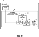
- FIG. 14 is a block diagram illustrating the overall configuration of the abnormal physical condition determination system according to the fourth example embodiment.
- the same components as those illustrated in FIG.1 carry the same reference numerals.
- the abnormal physical condition determination system 1 according to the fourth example embodiment includes the feature extraction unit 103, the feature accumulation unit 104, the feature relationship calculation unit 105, and the abnormal physical condition determination unit 106. That is, the abnormal physical condition determination system 1 according to the fourth example embodiment does not include the image acquisition unit 101 and the target detection unit 102 among the components of the abnormal physical condition determination system 1 according to the first example embodiment (see FIG. 1 ).
- the feature extraction unit 103 is configured to obtain an image captured by the cabin camera 50 and to extract feature quantities for determining the abnormal physical condition of a target person from the image.
- the components other than the feature quantity extraction unit 103 i.e., the feature accumulation unit 104, the feature relationship calculation unit 105, and the abnormal physical condition determining unit 106) are configured in the same manner as those in the first to third example embodiments.
- the detection of the target person by the target detection unit 102 (e.g., detection of the face area of the target person, etc.) is not performed.
- the image obtained by the feature extraction unit 103 is an image including an area suitable for extracting feature quantities (e.g., an image obtained by enlarging and imaging a facial periphery of the target person or the like).
- an imaging range of the cabin camera 50 may be adjusted to be an appropriate range in advance, or the cabin camera 50 may be provided with a function of automatically adjusting the imaging range.
- the feature extraction unit 103 may have a function of automatically detecting the area suitable for extracting feature quantities from the captured image and of extracting feature quantities from the area.
- the motion sickness of the occupant can be determined on the basis of the relationship between each feature quantity extracted from the image of the occupant.
- the fourth example embodiment since the system configuration is simplified, it is possible to suppress the cost and size of the apparatus.
- the fourth example embodiment can be also applied to the motion sickness that occurs in a movable body other than the vehicle 10 or the abnormal physical condition other than the motion sickness.
- An abnormal physical condition determination system described in Supplementary Note 1 is an abnormal physical condition determination system including: an extraction unit that extracts a plurality of feature quantities indicating a condition of a target person from an image of the target person; an accumulation unit that accumulates the plurality of feature quantities as time series data; a calculation unit that calculates a relationship between each feature quantity from the plurality of feature quantities accumulated in the accumulation unit; and a determination unit that determines an abnormal physical condition of the target person on the basis of the relationship.
- An abnormal physical condition determination system described in Supplementary Note 2 is the abnormal physical condition determination system described in Supplementary Note 1, wherein the calculation unit calculates the relationship from a degree of a change per unit time in the plurality of feature quantities.
- An abnormal physical condition determination system described in Supplementary Note 3 is the abnormal physical condition determination system described in Supplementary Note 1 or 2, wherein the calculation unit calculates a correlation or a ratio between different feature quantities as the relationship.
- An abnormal physical condition determination system described in Supplementary Note 4 is the abnormal physical condition determination system described in any one of Supplementary Notes 1 to 3, wherein the plurality of feature quantities includes feature quantities related to a position of a pupil of the target person, a direction of a face, or a gaze direction.
- An abnormal physical condition determination system described in Supplementary Note 5 is the abnormal physical condition determination system described in any one of Supplementary Notes 1 to 4, wherein the relationship includes at least one of a correlation between a face position and a position of a pupil, a correlation between a face pan direction and a gaze horizontal direction, and a correlation between a face tilt direction and a gaze vertical direction.
- An abnormal physical condition determination system described in Supplementary Note 6 is the abnormal physical condition determination system described in any one of Supplementary Notes 1 to 5, wherein the relationship includes at least one of a ratio in a moving velocity between a face gravity-center position and an eye position, a ratio in an angular velocity between a face pan direction and a gaze horizontal direction, and a ratio in the angular velocity between a face tilt direction and a gaze vertical direction.
- An abnormal physical condition determination system described in Supplementary Note 7 is the abnormal physical condition determination system described in any one of Supplementary Notes 1 to 6, wherein the determination unit determines and outputs a degree of the abnormal physical condition on the basis of the relationship.
- An abnormal physical condition determination system described in Supplementary Note 8 is the system for determining abnormal physical condition described in any one of Supplementary Notes 1 to 7, further comprising: a presentation unit that presents information about the abnormal physical condition of the target person corresponding to a determination result of the determination unit, to at least one of the target person and a person who is around the target person.
- An abnormal physical condition determination system described in Supplementary Note 9 is the abnormal physical condition determination system described in any one of Supplementary Notes 1 to 8, wherein the target person is an occupant of a vehicle, and the abnormal physical condition determination system further includes an output unit that outputs a control information for controlling the vehicle in accordance with the abnormal physical condition, on the basis of a determination result of the determination unit.
- An abnormal physical condition determination system described in Supplementary Note 10 is the abnormal physical condition determination system described in any one of Supplementary Notes 1 to 9, wherein the abnormal physical condition is a motion sickness.
- An abnormal physical condition determination method described in Supplementary Note 11 is an abnormal physical condition determination method including: extracting a plurality of feature quantities indicating a condition of a target person from an image of the target person; accumulating the plurality of feature quantities as time series data; calculating a relationship between each feature quantity from the plurality of feature quantities accumulated in the accumulation unit; and determining an abnormal physical condition of the target person on the basis of the relationship.
- a computer program described in Supplementary Note 12 is a computer program that operates a computer: to extract a plurality of feature quantities indicating a condition of a target person from an image of the target person; to accumulate the plurality of feature quantities as time series data; to calculate a relationship between each feature quantity from the plurality of feature quantities accumulated in the accumulation unit; and to determine an abnormal physical condition of the target person on the basis of the relationship.
Landscapes
- Engineering & Computer Science (AREA)
- Health & Medical Sciences (AREA)
- Life Sciences & Earth Sciences (AREA)
- Physics & Mathematics (AREA)
- General Health & Medical Sciences (AREA)
- Medical Informatics (AREA)
- Public Health (AREA)
- Biomedical Technology (AREA)
- Pathology (AREA)
- Theoretical Computer Science (AREA)
- Computer Vision & Pattern Recognition (AREA)
- General Physics & Mathematics (AREA)
- Veterinary Medicine (AREA)
- Biophysics (AREA)
- Animal Behavior & Ethology (AREA)
- Heart & Thoracic Surgery (AREA)
- Molecular Biology (AREA)
- Surgery (AREA)
- Multimedia (AREA)
- Mechanical Engineering (AREA)
- Oral & Maxillofacial Surgery (AREA)
- Epidemiology (AREA)
- Primary Health Care (AREA)
- General Engineering & Computer Science (AREA)
- Databases & Information Systems (AREA)
- Automation & Control Theory (AREA)
- Mathematical Physics (AREA)
- Transportation (AREA)
- Radiology & Medical Imaging (AREA)
- Psychiatry (AREA)
- Social Psychology (AREA)
- Nuclear Medicine, Radiotherapy & Molecular Imaging (AREA)
- Psychology (AREA)
- Hospice & Palliative Care (AREA)
- Data Mining & Analysis (AREA)
- Educational Technology (AREA)
- Developmental Disabilities (AREA)
- Child & Adolescent Psychology (AREA)
- Software Systems (AREA)
- Power Engineering (AREA)
Abstract
Description
- The present invention relates to an abnormal physical condition determination system, an abnormal physical condition determination method, and a computer program that determine an abnormal physical condition of a target person.
- A known system of this type determines a condition of a target person on the basis of an image obtained by imaging the target person. For example,
Patent Literature 1 discloses a technique/technology of estimating a condition of a driver from a position of a face, a direction of the face, a gaze direction, and the like that are obtained by analyzing a face image.Patent Literature 2 discloses a technique/technology of detecting a face position from a face image and estimating the condition of the driver by using a degree of opening and closing of an eye, the gaze direction, the direction of the face, and the like. - As another related art, for example,
Patent Literature 3 discloses a technique/technology of detecting a feature point vector from a plurality of feature points extracted from image data on a face. -
- Patent Literature 1: International Publication No.
WO2017/209225 - Patent Literature 2: International Publication No.
WO2017/208529 - Patent Literature 3: International Publication No.
WO2016/013090 - When an attempt is made to determine the condition of the target person by directly utilizing a feature, such as the position of the face, the direction of the face, and the gaze direction, it is assumed that the condition will be affected by environmental variations such as, for example, individual differences and lighting conditions. In this case, depending on an environment when the condition is determined, there is a possibility that the accuracy of the determination is reduced. In other words, in the techniques/technologies as described in
Patent Literatures 1 2 and 3, the condition of the target person cannot be accurately determined depending on the circumstances, which is technically problematic. - The present invention has been made in view of the above problems, and it is an example object of the present invention is to provide an abnormal physical condition determination system, an abnormal physical condition determination method, and a computer program that are appropriately determine an abnormal physical condition of a target person.
- An abnormal physical condition determination system according to an example aspect of the present invention includes: an extraction unit that extracts a plurality of feature quantities indicating a condition of a target person from an image of the target person; an accumulation unit that accumulates the plurality of feature quantities as time series data; a calculation unit that calculates a relationship between each feature quantity from the plurality of feature quantities accumulated in the accumulation unit; and a determination unit that determines an abnormal physical condition of the target person on the basis of the relationship.
- An abnormal physical condition determination method according to an example aspect of the present invention includes: extracting a plurality of feature quantities indicating a condition of a target person from an image of the target person; accumulating the plurality of feature quantities as time series data; calculating a relationship between each feature quantity from the plurality of feature quantities accumulated in the accumulation unit; and determining an abnormal physical condition of the target person on the basis of the relationship.
- A computer program of the present invention operates a computer: to extract a plurality of feature quantities indicating a condition of a target person from an image of the target person; to accumulate the plurality of feature quantities as time series data; to calculate a relationship between each feature quantity from the plurality of feature quantities accumulated in the accumulation unit; and to determine an abnormal physical condition of the target person on the basis of the relationship.
- According to the abnormal physical condition determination system, the abnormal physical condition determination method, and the computer program in the respective aspects described above, it is possible to appropriately determine the abnormal condition of the target person.
-
- [
FIG. 1] FIG. 1 is a block diagram illustrating an overall configuration of an abnormal physical condition determination system according to a first example embodiment. - [
FIG. 2] FIG. 2 is a block diagram illustrating an overall configuration of an abnormal physical condition determination system according to a modified example. - [
FIG. 3] FIG. 3 is a block diagram illustrating a hardware configuration of the abnormal physical condition determination system according to the first example embodiment. - [
FIG. 4] FIG. 4 is a flowchart illustrating a flow of operation of the abnormal physical condition determination system according to the first example embodiment. - [
FIG. 5] FIG. 5 is a table illustrating a specific example of a feature vector. - [
FIG. 6] FIG. 6 is a block diagram illustrating an overall configuration of an abnormal physical condition determination system according to a second example embodiment. - [
FIG. 7] FIG. 7 is a schematic diagram illustrating an interior configuration of a vehicle to which the abnormal physical condition determination system according to the second example embodiment is applied. - [
FIG. 8] FIG. 8 is a diagram illustrating an example of a display area of a display unit. - [
FIG. 9] FIG. 9 isversion 1 of a diagram illustrating a display example in the display area when an occupant has a car sickness. - [
FIG. 10] FIG. 10 isversion 2 of a diagram illustrating a display in the display area when the occupant has a car sickness. - [
FIG. 11] FIG. 11 is a diagram illustrating an example of an icon illustrating a degree of the car sickness. - [
FIG. 12] FIG. 12 is a diagram illustrating another display example in the display area of the display unit. - [
FIG. 13] FIG. 13 is a block diagram illustrating an overall configuration of an abnormal physical condition determination system according to a third example embodiment. - [
FIG. 14] FIG. 14 is a block diagram illustrating an overall configuration of an abnormal physical condition determination system according to a fourth example embodiment. - Hereinafter, example embodiments of an abnormal physical condition determination system, an abnormal physical condition determination method, and a computer program will be described with reference to the drawings.
- An abnormal physical condition determination system according to a first example embodiment will be described with reference to
FIG. 1 to FIG. 5 . In the following, a description will be made to an example in which the abnormal physical condition determination system is an apparatus that determines an abnormal physical condition of an occupant of a vehicle (specifically, a motion sickness). - First, an overall configuration of the abnormal physical condition determination system according to the first example embodiment will be described with reference to
FIG. 1 andFIG. 2 .FIG. 1 is a block diagram illustrating the overall configuration of the abnormal physical condition determination system according to a first example embodiment.FIG. 2 is a block diagram illustrating an overall configuration of an abnormal physical condition determination system according to a modified example. - As illustrated in
FIG. 1 , an abnormal physicalcondition determination system 1 according to the first example embodiment is installed in avehicle 10 including acabin camera 50. The abnormal physicalcondition determination system 1 includes, as functional blocks for realizing its functions, animage acquisition unit 101, atarget detection unit 102, afeature extraction unit 103, afeature accumulation unit 104, a featurerelationship calculation unit 105, and an abnormal physicalcondition determination unit 106. - The
image acquisition unit 101 is configured to obtain an image captured by the cabin camera 50 (specifically, an image of an occupant of the vehicle 10). The image obtained by theimage acquisition unit 101 is configured to be outputted to thetarget detection unit 102. - The
target detection unit 102 is configured to detect a target person whose abnormal physical condition is determined, from the image obtained by theimage acquisition unit 101. Thetarget detection unit 102 detects, for example, an area in which the target person appears, (e.g., a face area of the target person, etc.) from the captured image. Incidentally, as the existing techniques/technologies can be adopted as appropriate, a detailed description of a specific method of detecting the target person from the captured image will be omitted here. A detection result of thetarget detection unit 102 is configured to be outputted to thefeature extraction unit 103. - The
feature extraction unit 103 is configured to extract feature quantities for determining the abnormal physical condition of the target person from the area detected by thetarget detection unit 102. The feature quantities extracted by thefeature extraction unit 103 include, for example, feature quantities related to the position of a pupil of the occupant, the direction of a face, a gaze direction, the color of the face, the position of a face feature point, and a degree of opening of a lid. Thefeature extraction unit 103 extracts a plurality of types of feature quantities from the occupant. The feature quantities extracted by thefeature extraction unit 103 are configured to be outputted to each of thefeature accumulation unit 104 and the featurerelationship calculation unit 105. - The
feature accumulation unit 104 is configured to accumulate the feature quantities extracted by thefeature extraction unit 103, as time series data. Thefeature accumulation unit 104 accumulates the feature quantities, for example, in units of frames arranged in time series. The feature quantities accumulated in thefeature accumulation unit 104 are configured to be appropriately outputted to the featurerelationship calculation unit 105. - The feature
relationship calculation unit 105 is configured to calculate a relationship between each feature quantity (i.e., a relationship between different types of feature quantities), from time series data on a plurality of types of feature quantities. More specifically, the featurerelationship calculation unit 105 calculates the relationship between each feature quantity, from the feature quantities extracted by the feature extraction unit 103 (in other words, current feature quantities) and the feature quantities read from the feature accumulation unit 104 (in other words, past feature quantities). The relationship between each feature quantity is calculated, for example, as a feature vector having a plurality of dimensions. The relationship between each feature quantity calculated by the featurerelationship calculation unit 105 is configured to be outputted to the abnormal physicalcondition determination unit 106. - The abnormal physical
condition determination unit 106 determines the abnormal physical condition of the occupant on the basis of the relationship between each feature quantity calculated by the featurerelationship calculation unit 105. The abnormal physicalcondition determination unit 106 determines, for example, whether or not the occupant is in an abnormal physical condition, or a degree of the abnormal physical condition of the occupant. Incidentally, the determination of the abnormal physical condition can be performed by setting a relevance between the abnormal physical condition and the relationship of feature quantities in advance. For example, a threshold for the feature vector may be set, and when the calculated feature vector exceeds the threshold, it may be determined that the occupant is in the abnormal physical condition. Furthermore, the abnormal physicalcondition determination unit 106 may be configured to learn the threshold associated with the determination. For example, the abnormal physicalcondition determination unit 106 may perform learning by using correct data or the like obtained by an input made by the occupant. - As illustrated in
FIG. 2 , the abnormal physicalcondition determination system 1 may be provided in anexternal server 20 that is outside thevehicle 10. That is, the abnormal physicalcondition determination system 1 may not necessarily be installed in thevehicle 10. Instead of all the components of the abnormal physicalcondition determination system 1, a part of the components of the abnormal physicalcondition determination system 1 may be provided in theexternal server 20. - Next, a hardware configuration of the abnormal physical
condition determination system 1 according to the first example embodiment will be described with reference toFIG. 3. FIG. 3 is a block diagram illustrating the hardware configuration of the abnormal physical condition determination system according to the first example embodiment. - As illustrated in
FIG. 3 , the abnormal physicalcondition determination system 1 according to the first example embodiment includes a CPU (Central Processing Unit) 11, a RAM (Random Access Memory) 12, a ROM (Read Only Memory) 13, and astorage apparatus 14. The abnormal physicalcondition determination system 1 may further include aninput apparatus 15 and anoutput apparatus 16. TheCPU 11, theRAM 12, theROM 13, thestorage apparatus 14, theinput apparatus 15, and theoutput apparatus 16 are connected through adata bus 17. - The
CPU 11 reads a computer program. For example, theCPU 11 is configured to read a computer program stored by at least one of theRAM 12, theROM 13 and thestorage apparatus 14. Alternatively, theCPU 11 may read a computer program stored by a computer readable recording medium by using a not-illustrated recording medium reading apparatus. TheCPU 11 may obtain (i.e., read) a computer program from a not-illustrated apparatus that is located outside the physicalcondition determination system 1 through a network interface. TheCPU 11 controls theRAM 12, thestorage apparatus 14, theinput apparatus 15, and theoutput apparatus 16 by executing the read computer program. Especially in the example embodiment, when theCPU 11 executes the computer program read by theCPU 11, a functional block for determining the abnormal physical condition is implemented in theCPU 11. - The
RAM 12 temporarily stores the computer program to be executed by theCPU 11. TheRAM 12 temporarily stores the data that is temporarily used by theCPU 11 when theCPU 11 executes the computer program. TheRAM 12 may be, for example, a D-RAM (Dynamic RAM). - The
ROM 13 stores the computer program to be executed by theCPU 11. TheROM 13 may otherwise store fixed data. TheROM 13 may be, for example, a P-ROM (Programmable ROM). - The
storage apparatus 14 stores the data that is stored for a long term by the abnormal physicalcondition determination system 1. Thestorage apparatus 14 may operate as a temporary storage apparatus of theCPU 11. Thestorage apparatus 14 may include, for example, at least one of a hard disk apparatus, a magneto-optical disk apparatus, an SSD (Solid State Drive), and a disk array apparatus. - The
input apparatus 15 is an apparatus that receives an input instruction from a user of the abnormal physicalcondition determination system 1. Theinput apparatus 15 may include, for example, at least one of a keyboard, a mouse, and a touch panel. - The
output apparatus 16 is an apparatus that outputs information about the abnormal physicalcondition determination system 1 to the outside. For example, theoutput apparatus 16 may be a display apparatus (e.g., a display) that is configured to display the information about the abnormal physicalcondition determination system 1. - Next, with reference to
FIG. 4 , a flow of operation of the abnormal physicalcondition determination system 1 according to the first example embodiment will be described.FIG. 4 is a flowchart illustrating the flow of the operation of the abnormal physical condition determination system according to the first example embodiment. - As illustrated in
FIG. 4 , in operation of the abnormal physicalcondition determination system 1 according to the first example embodiment, first, theimage acquisition unit 101 obtains the image of the occupant captured by the cabin camera 50 (step S101). Then, thetarget detection unit 102 detects the face area from the image of the occupant (step S102). When the feature quantities are detected from other than the face area, another area corresponding to the feature quantities may be detected. - Then, the
feature extraction unit 103 extracts the feature quantities from the face area (step S103). Then, thefeature accumulation unit 104 accumulates (i.e., stores) the extracted feature quantities (step S104). - Then, the feature
relationship calculation unit 105 determines whether or not the feature quantities are accumulated for a predetermined number of frames in the feature accumulation unit 104 (step S105). Here, the " predetermined number of frames" is a value corresponding to an amount of feature quantities sufficient to calculate the relationship between each feature quantity, and an optimum value (e.g., the number of frames corresponding to 5 seconds) is set in advance. When it is determined that the feature quantities are not accumulated for a predetermined number of frames (the step S105: NO), the process is performed from the step S101 again. That is, the process of extracting the feature quantities from the image of the occupant and accumulating them is repeated. - On the other hand, when it is determined that the feature quantities are accumulated for a predetermined number of frames (the step S105: YES), the feature
relationship calculation unit 105 calculates the relationship between each feature quantity (step S106). Then, the abnormal physicalcondition determination unit 106 determines the abnormal physical condition of the occupant (here, a motion sickness) on the basis of the calculated relationship between each feature quantity (step S107). - Incidentally, a series of process steps described above is performed while the
vehicle 10 is running. The abnormal physicalcondition determination system 1 may start the operation, for example, when thevehicle 10 starts to run. Furthermore, it may start the operation at a timing after a lapse of a predetermined time (a time in which the abnormality supposedly begins to appear in the physical condition of the occupant) from the start of the running. Here, the predetermined time may be arbitrarily set. Alternatively, the predetermined time may be set on the basis of a history information, wherein a time from the start of the running until the abnormality begins to appear in the physical condition of the occupant is stored as the history information. In this way, it is possible to reduce an unnecessary process in a period in which the occupant is not in an abnormal physical condition. Alternatively, the abnormal physicalcondition determination system 1 may start the operation at a timing at which the face of the occupant can be normally detected or at a timing at which the occupant gets in the vehicle. In this way, the face of the occupant can be tracked, and it is thus possible to prevent a situation in which the face of the occupant cannot be detected even though the occupant is in the abnormal physical condition. Alternatively, the abnormal physicalcondition determination system 1 may start the operation on the basis of a behavior information about the vehicle (e.g., at a timing at which a threshold of an acceleration sensor becomes greater than or equal to a predetermined threshold). In this way, it is possible to reduce an unnecessary process when the vehicle takes a behavior that hardly causes the abnormal physical condition. - Furthermore, the abnormal physical
condition determination system 1 ends the operation, for example, at a timing when thevehicle 10 stops running. Alternatively, it may end the operation on the basis of the behavior information about the vehicle (e.g., at a timing at which the threshold of the acceleration sensor is less than or equal to a predetermined threshold). - Next, with reference to
FIG. 5 , the feature vector (i.e., the relationship between each feature quantity generated in the step S106 inFIG. 4 ) used in the abnormal physicalcondition determination system 1 according to the first example embodiment will be specifically described.FIG. 5 is a table illustrating a specific example of the feature vector. - In
FIG. 5 , it is assumed that thefeature extraction unit 103 extracts positions of the occupant's right and left eye pupils, a face direction angle (pan, tilt, and roll directions), and a gaze angle (horizontal and vertical directions) as the feature quantities. In this case, the featurerelationship calculation unit 105 calculates the relationship between the above-described plurality of types of feature quantities, as a multi-dimensional feature vector. - Specifically, the feature
relationship calculation unit 105 calculates an eight-dimensional feature vector including (1) a correlation between a face position and a right pupil position, (2) a correlation between the face position and a left pupil position, (3) a correlation between a face pan direction and a gaze horizontal direction, (4) a correlation between a face tilt direction and a gaze vertical direction, (5) a ratio in a moving velocity between a face gravity-center position and a right eye position, (6) a ratio in the moving velocity between the face gravity-center position and a left eye position, (7) a ratio in an angular velocity between the face pan direction and the gaze horizontal direction, and (8) a ratio in the angular velocity between the face tilt direction and the gaze vertical direction. Taking (1) as an example, the correlation is obtained by dividing the covariance of the face position and the right pupil by the product of a standard deviation of the face position and a standard deviation of the right pupil. - Incidentally, for each element of the feature vector may be appropriately weighted. The weight in this case may be determined in accordance with a face condition estimated from the image of the face area. Specifically, when the occupant wears glasses, the weight of the feature quantity related to the eyes may be reduced because the accuracy of the feature quantity obtained for the eyes is considered to be reduced. Furthermore, the feature vector does not need to be eight-dimensional, and may have dimensionality that is appropriately set.
- The abnormal physical
condition determination unit 106 determines that the occupant is in the abnormal physical condition on the basis of the calculated relationship between each feature quantity. Specifically, when the correlation and the ratio calculated by the featurerelationship calculation unit 105 are greater than or equal to a predetermined value, it is determined that the occupant is in the abnormal physical condition. Incidentally, in calculating the eight-dimensional feature vector including the above-described (1) to (8), it may be determined that the occupant is in the abnormal physical condition when any one or more correlations or ratios are greater than or equal to a predetermined value, or it may be determined that the occupant is in the abnormal physical condition when all the eight correlations and ratios are greater than or equal to respective predetermined values. - When having a motion sickness, the occupant feels vertigo, or dizziness in eye opening. On the other hand, the above-described (1) to (8) in the feature vector are calculated as the relationship between a pair of feature quantities that normally changes in the same manner. Therefore, according to the feature vector described above, it is possible to discriminate a situation in which the movements of the face and eyes do not correspond to each other due to dizziness, and it is possible to suitably determine the occurrence of the motion sickness.
- Incidentally, the feature vector described above is merely an example, and another relationship of feature quantities may be used. For example, a pair of feature quantities for calculating their relationship may be determined in accordance with the type of the abnormal physical condition that is to be determined.
- Next, a technical effect obtained by the abnormal physical
condition determination system 1 according to the first example embodiment will be described. - As described in
FIG. 1 to FIG. 5 , according to the abnormal physicalcondition determination system 1 in the first example embodiment, it is possible to determine the motion sickness of the occupant on the basis of the feature quantities extracted from the image of the occupant. Especially in this example embodiment, the motion sickness is determined on the basis of the relationship between a plurality of feature quantities, rather than by directly utilizing the extracted feature quantities. Therefore, for example, it is possible to suppress an influence of environmental variations, such as individual differences and lighting conditions, and it is possible to determine the motion sickness with high accuracy. In addition, since the feature quantities that are time series data are utilized, unlike the case where the feature quantities are extracted from only one image, a change per unit time in the feature quantities can also be considered. Therefore, it is possible to determine the motion sickness, more accurately. - The above example embodiment describes an example of determining the motion sickness of the occupant of the
vehicle 10, but the motion sickness of the occupant of a movable body other than thevehicle 10, such as, for example, a ship or an airplane, may be also determined. In addition, an abnormal physical condition other than the motion sickness may be determined. Specifically, a determination may be performed on dizziness that may occur in the use of a VR (Virtual Reality) apparatus (so-called VR sickness) or the like. If the feature quantity related to the face of the target person is utilized as in the example embodiment, it is possible to appropriately determine the abnormal physical condition that is especially accompanied by dizziness, but it can also be applied to the determination of another abnormal physical condition that is not accompanied by dizziness, by utilizing the relationship between appropriate feature quantities. - Next, the abnormal physical
condition determination system 1 according to a second example embodiment will be described with reference toFIG. 6 to FIG. 12 . The second example embodiment is partially different from the above-described first example embodiment only in the configuration and operation, and is substantially the same in the other parts. Therefore, the parts that differ from the first example embodiment will be described in detail below, and the other overlapping parts will be omitted as appropriate. - First, an overall configuration of the abnormal physical
condition determination system 1 according to the second example embodiment will be described with reference toFIG. 6 andFIG. 7 .FIG. 6 is a block diagram illustrating the overall configuration of the abnormal physical condition determination system according to the second example embodiment.FIG. 7 is a schematic diagram illustrating an interior configuration of a vehicle to which the abnormal physical condition determination system according to the second example embodiment is applied. Incidentally, inFIG. 6 , the same components as those illustrated inFIG. 1 carry the same reference numerals. - As illustrated in
FIG. 6 , the abnormal physicalcondition determination system 1 according to the second example embodiment includes a determinationresult output unit 107 in addition to the components of the abnormal physicalcondition determination system 1 according to the first example embodiment (seeFIG. 1 ). - The abnormal physical
condition determination unit 106 may identify a cause of the abnormal physical condition of the occupant from the information indicating the behavior of thevehicle 10. In this case, the abnormal physicalcondition determination unit 106 may be configured to obtain the information indicating the behavior of thevehicle 10 from a not-illustrated sensor (e.g., an acceleration sensor or the like) provided in thevehicle 10. Furthermore, the abnormal physicalcondition determination unit 106 may identify the cause of the abnormal physical condition of the occupant from an analysis result of the image of the occupant, or the like. In this case, the abnormal physicalcondition determination unit 106 may be configured to extract the feature quantity that allows the cause of the abnormal physical condition to be determined, from an image or the like including a whole body of the occupant. In addition, a not-illustrated abnormal physical condition cause identification unit may identify the cause of the abnormal physical condition of the occupant. - For example, when it is determined that the occupant is in the abnormal physical condition, the abnormal physical
condition determination unit 106 obtains an acceleration of the vehicle at the determined timing. The abnormal physicalcondition determination unit 106 compares the obtained acceleration with a threshold stored in advance (e.g., an acceleration that likely causes the abnormal physical condition), thereby to determine whether or not the abnormal physical condition of the occupant is due to the acceleration of thevehicle 10. The obtained acceleration may be an acceleration at a timing a predetermined period before the timing at which it is determined that the occupant is in the abnormal physical condition. Alternatively, it may be an acceleration in a predetermined period until the timing at which it is determined that the occupant is in the abnormal physical condition. Furthermore, in place of or in addition to the acceleration, at least one of a velocity, an angular velocity, an angular velocity in a yaw direction, an angular acceleration in the yaw direction, an angular velocity in a pitch direction, an angular acceleration in the pitch direction, an angular velocity in a roll direction, and an angular acceleration in the roll direction may be obtained. The cause may be identified on the basis of at least one of them or all of them. - Incidentally, the abnormal physical
condition determination unit 106 may identify the cause of the abnormal physical condition without comparing the detected acceleration or the like with the threshold. For example, with respect to the acceleration detected at the timing at which it is determined that the occupant is in the abnormal physical condition, it can be determined that the acceleration itself is the cause of the abnormal physical condition. Therefore, the acceleration detected at the timing at which it is determined that the occupant is in the abnormal physical condition or the like may be identified as the cause of abnormal physical condition as it is. - Furthermore, for example, when it is determined that the occupant is in the abnormal physical condition, the abnormal physical
condition determination unit 106 specifies what action (e.g., reading, eating and drinking, etc.) the occupant is taking, from a camera image at the determined timing. The abnormal physicalcondition determination unit 106 determines whether or not the abnormal physical condition of the occupant is due to the action of the occupant, from whether or not the specified action corresponds to the cause of the abnormal physical condition stored in advance (e.g., a table information about the action that likely causes the abnormal physical condition). Incidentally, the camera image used to identify the cause may be captured or photographed at a timing a predetermined period before the timing at which it is determined that the occupant is in the abnormal physical condition. Alternatively, it may be captured in a predetermined period until the timing at which it is determined that the occupant is in the abnormal physical condition. In addition, the table information about the action that likely causes the abnormal physical condition may be associated with the degree of the abnormal physical condition for each action. Alternatively, multiple actions may be obtained, and the cause may be identified on the basis of at least one of them or all of them. - The determination
result output unit 107 is configured to output a determination result of the abnormal physicalcondition determination unit 106, to adisplay unit 301 mounted on thevehicle 10. That is, the determinationresult output unit 107 outputs information about the physical condition abnormal of the occupant, so as to present to the occupant or a fellow occupant. Incidentally, the determinationresult output unit 107 may be configured to output the information about the abnormal physical condition of the occupant, to a not-illustrated speaker or the like. - As illustrated in
FIG. 7 , thedisplay unit 301 is configured as a display or the like provided on a front side of the vehicle. Thecabin camera 50 is provided as acamera 50a that is configured to image the faces ofoccupants 201 in a driver's seat and a passenger seat, and acamera 50b that is configured to image the face of anoccupant 202 in a rear seat. - Next, a display example by the abnormal physical
condition determination system 1 according to the second example embodiment (i.e., a specific display example of the display unit 301) will be described with reference toFIG. 8 to FIG. 12 .FIG. 8 is a diagram illustrating an example of a display area of the display unit.FIG. 9 isversion 1 of a diagram illustrating a display example in the display area when the occupant has a car sickness.FIG. 10 isversion 2 of a diagram illustrating a display in the display area when the occupant has a car sickness.FIG. 11 is a diagram illustrating an example of an icon illustrating a degree of the car sickness.FIG. 12 is a diagram illustrating another display example in the display area of the display unit. - The display area of the
display unit 301 may include a cause/measure information display area. The display area of thedisplay unit 301 may also include an occupant information display area. An example is illustrated inFIG. 8 . The cause/measure information display area located on a left side shows at least one of a cause and a measure in accordance with a determination result about the motion sickness. If there is no occupant who has a motion sickness, nothing may be displayed in the cause/measure information display area. The occupant information display area located on a right side shows information about the occupant of thevehicle 10 and information about instructions to the occupant. In this example, since there are a total of three occupants, which are one in the driver's seat, one in the passenger seat, and one in the left rear seat, an icon indicating the presence of the occupant (a circular icon inFIG. 8 ) is displayed in each seat. - In the example illustrated in
FIG. 9 , the occupant in the left rear seat is having a motion sickness. For this reason, the icon corresponding to the occupant in the left rear seat in the occupant information display area is changed to an icon indicating the motion sickness. In addition, an arrow icon (an icon in front of the vehicle) in the occupant information display area is turned on. This icon indicates that it recommends pulling over. In such cases, a driving route for pulling over or parking thevehicle 10 in a parking space may be displayed in conjunction with a navigation apparatus. - The cause/measure information display area shows the cause of the motion sickness of the occupant in the left rear seat (here, braking and reading). Incidentally, the cause of the motion sickness may be identified by the abnormal physical
condition determination unit 106 or a not-illustrated abnormal physical condition cause specifying unit, as described above. When there is more than one occupant who is having a motion sickness, the cause/measure information display area may be divided in accordance with the number of the occupants and each division may perform a corresponding display. In addition, although it is not illustrated here, more specific instructions may be displayed as a measure against the abnormal physical condition, such as "Driver should be careful not to apply a brake" and "Person in the left rear seat should stop reading", on the basis of the identified cause of the abnormal physical condition. - Incidentally, the display of the cause and measure may use a template information prepared in advance. For the template information, contents of the cause such as "sudden braking" and "reading" and contents of instructions such as "the driver should drive carefully" and "the occupants should stop reading and drinking" may be set as at least one display information. The template information may be an icon image indicating the cause and measure. In addition, when the abnormal physical condition of the occupant is detected, the template information may be used without identifying the cause of the abnormal physical condition.
- Alternatively, in addition to or in place of the display of the
display unit 301, voice guidance may be provided. - The example illustrated in
FIG. 10 is a display example obtained after thevehicle 10 is pulled over after the situation illustrated inFIG. 9 occurs. In the occupant information display area, the arrow icon that is turned on inFIG. 9 is turned off because thevehicle 10 is pulled over. On the other hand, an arrow icon near the occupant in the left rear seat is turned on. This arrow icon recommends the occupant in the left rear seat to get out of thevehicle 10. - The cause/measure information display area shows contents of an instruction that is "Please get out and take a deep breath". That is, a measure to reduce the motion sickness is displayed. Incidentally, the display example here is merely an example, and another measure may be displayed. For example, such a display that encourages the occupant to look out of the window, to adjust the seat to easily look outside, to move to the passenger seat, to take a motion sickness pill, or the like may be provided. Alternatively, a driving route suitable to take the measure may be displayed in conjunction with a navigation apparatus. Specifically, a choice of whether or not to the occupant needs a motion sickness pill may be displayed and the occupant's reply may be accepted (an inquiry may be made by audio and the occupant's reply may be accepted by voice recognition), and when the occupant replies that he or she needs it, a driving route to a nearby pharmacy may be displayed.
- One of the causes of the motion sickness is that the occupant other than the driver cannot predict the behavior of the
vehicle 10. As a measure for such a cause, when there is an occupant who has a motion sickness, a display or a voice guidance related to the behavior of thevehicle 10 may be provided. For example, on the basis of information about a driving road, in which direction and in how many seconds thevehicle 10 turns may be voice-guided. Alternatively, in which direction thevehicle 10 turns or in how many seconds thevehicle 10 moves may be displayed on thedisplay unit 301. - As illustrated in
FIG. 11 , the icon of the occupant displayed in the occupant information display area varies depending on the degree of the motion sickness. For example, in Example 1, an expression of the icon varies depending on the degree of the motion sickness. In Example 2, brightness and color of the icon varies depending on the degree of the motion sickness. When changing the color of the icon, it is preferable to adopt a color from which emergency can be intuitively grasped. Specifically, it may be changed to "green" when the degree of the motion sickness is slight, to "yellow" when the degree of the motion sickness is moderate, and to "red" when the degree is severe. Although an example of changing the icon in three stages is illustrated here, the number of types of the icon may be increased or reduced in accordance with the degree, such as, for example, in five stages. - As illustrated in
FIG. 12 , the cause/measure information display area may be icon-displayed. The icons inFIG. 12 indicate the cause of the motion sickness. The icons in the upper row indicate "reading", "sudden braking", and "not looking outside" in order from the left. The icons in the lower row indicate "eating and drinking", "sudden start" and "vibration" in order from the left. In the example ofFIG. 12 , the icons of "reading" and "sudden braking" are turned on because they are estimated to be the cause of the motion sickness. - Next, a technical effect obtained by the physical condition
abnormality determination system 1 according to the second example embodiment will be described. - As described in
FIG. 6 to FIG. 12 , according to the abnormal physicalcondition determination system 1 in the second example embodiment, it is possible to accurately inform the occupant of thevehicle 10 of a current situation by displaying the determination result about the motion sickness. Furthermore, the display of the cause and measure of the motion sickness makes it easy to attempt to remove the motion sickness. As in the first example embodiment, the second example embodiment can be also applied to the motion sickness that occurs in a movable body other than thevehicle 10 or the abnormal physical condition other than the motion sickness. - Next, the abnormal physical
condition determination system 1 according to a third example embodiment will be described with reference toFIG. 13 . The third example embodiment is partially different from the above-described first and second example embodiments only in the configuration and operation, and is substantially the same in the other parts. Therefore, the parts that differ from the first and second example embodiments will be described in detail below, and the other overlapping parts will be omitted as appropriate. - First, an overall configuration of the abnormal physical
condition determination system 1 according to the third example embodiment will be described with reference toFIG. 13. FIG. 13 is a block diagram illustrating the overall configuration of the abnormal physical condition determination system according to the third example embodiment. Incidentally, inFIG. 13 , the same components as those illustrated inFIG. 1 carry the same reference numerals. - As illustrated in
FIG. 13 , the abnormal physicalcondition determination system 1 according to the third example embodiment includes a controlinformation output unit 108 in addition to the components of the abnormal physicalcondition determination system 1 according to the first example embodiment (seeFIG. 1 ). - The control
information output unit 108 generates and outputs a control information for controlling thevehicle 10 on the basis of the determination result about the abnormal physical condition. The control information outputted from the controlinformation output unit 108 is configured to be inputted to avehicle control unit 302 of thevehicle 10. Thevehicle control unit 302 is a control unit that is configured to control each unit and part of thevehicle 10, and performs a control corresponding to the control information. - Next, contents of the control performed by the control information outputted from the control information output unit 108 (in other words, contents of the control performed by the vehicle control unit 302) will be specifically described.
- The control
information output unit 108 outputs, for example, the control information about autonomous driving of thevehicle 10. Specifically, the controlinformation output unit 108 may output the control information for allowing the elimination of a low-frequency motion in a motion control unit that controls the movement of thevehicle 10. In this way, it is possible to prevent minute vibration that causes the motion sickness. The controlinformation output unit 108 may output the control information for allowing the avoidance of sudden braking or sudden start. The controlinformation output unit 108 may output such a control information that allows thevehicle 10 to be slowly pulled over. The controlinformation output unit 108 may output the control information that when thevehicle 10 is running at anautonomous driving level 3 or higher (i.e., at a level where the driver is hardly involved in driving), the autonomous driving level is reduced to one of 0 to 2 (i.e., at a level where the driver is involved in driving) so that the driver can pull over. - Furthermore, the control
information output unit 108 may output the control information for controlling air conditioning in a vehicle cabin. That is, it may output information for changing a state of the air in the vehicle cabin to a state in which the occupant hardly has a motion sickness. Alternatively, the controlinformation output unit 108 may output the control information for adjusting the position of a movable navigation display unit or a movable smartphone holder in the vehicle cabin or the like at the level that outside scenery comes in sight when the occupant looks at a display screen. That is, it may output information for changing the occupant's field of view into the state in which the occupant hardly has a motion sickness. - Next, a technical effect obtained by the physical condition
abnormality determination system 1 according to the third example embodiment will be described. - As described in
FIG. 13 , according to the abnormal physicalcondition determination system 1 in the third example embodiment, it is possible to realize a situation in which the motion sickness is easily eliminated or a situation in which the motion sickness hardly occurs, by performing the control corresponding to the determination result about the motion sickness. As in the first and second example embodiments, the third example embodiment can be also applied to the motion sickness that occurs in a movable body other than thevehicle 10 or the abnormal physical condition other than the motion sickness. - Next, the abnormal physical
condition determination system 1 according to a fourth example embodiment will be described with reference toFIG. 14 . The fourth example embodiment is partially different from the above-described first to third example embodiments only in the configuration and operation, and is substantially the same in the other parts. Therefore, the parts that differ from the first to third example embodiments will be described in detail below, and the other overlapping parts will be omitted as appropriate. - First, an overall configuration of the abnormal physical
condition determination system 1 according to the fourth example embodiment will be described with reference toFIG. 14. FIG. 14 is a block diagram illustrating the overall configuration of the abnormal physical condition determination system according to the fourth example embodiment. Incidentally, inFIG. 14 , the same components as those illustrated inFIG.1 carry the same reference numerals. - As illustrated in
FIG. 14 , the abnormal physicalcondition determination system 1 according to the fourth example embodiment includes thefeature extraction unit 103, thefeature accumulation unit 104, the featurerelationship calculation unit 105, and the abnormal physicalcondition determination unit 106. That is, the abnormal physicalcondition determination system 1 according to the fourth example embodiment does not include theimage acquisition unit 101 and thetarget detection unit 102 among the components of the abnormal physicalcondition determination system 1 according to the first example embodiment (seeFIG. 1 ). - The
feature extraction unit 103 according to the fourth example embodiment is configured to obtain an image captured by thecabin camera 50 and to extract feature quantities for determining the abnormal physical condition of a target person from the image. The components other than the feature quantity extraction unit 103 (i.e., thefeature accumulation unit 104, the featurerelationship calculation unit 105, and the abnormal physical condition determining unit 106) are configured in the same manner as those in the first to third example embodiments. - Especially in the fourth example embodiment, as in the first to third example embodiments already described, the detection of the target person by the target detection unit 102 (e.g., detection of the face area of the target person, etc.) is not performed. For this reason, it is preferable that the image obtained by the
feature extraction unit 103 is an image including an area suitable for extracting feature quantities (e.g., an image obtained by enlarging and imaging a facial periphery of the target person or the like). In order to capture such an image, for example, an imaging range of thecabin camera 50 may be adjusted to be an appropriate range in advance, or thecabin camera 50 may be provided with a function of automatically adjusting the imaging range. Alternatively, thefeature extraction unit 103 may have a function of automatically detecting the area suitable for extracting feature quantities from the captured image and of extracting feature quantities from the area. - Next, a technical effect obtained by the physical condition
abnormality determination system 1 according to the fourth example embodiment will be described. - As described in
FIG. 14 , according to the abnormal physicalcondition determination system 1 in the fourth example embodiment, as in the first example embodiment, the motion sickness of the occupant can be determined on the basis of the relationship between each feature quantity extracted from the image of the occupant. Especially in the fourth example embodiment, since the system configuration is simplified, it is possible to suppress the cost and size of the apparatus. As in the first to third example embodiments, the fourth example embodiment can be also applied to the motion sickness that occurs in a movable body other than thevehicle 10 or the abnormal physical condition other than the motion sickness. - The example embodiments described above may be described in, but not limited to, the following Supplementary Notes.
- An abnormal physical condition determination system described in
Supplementary Note 1 is an abnormal physical condition determination system including: an extraction unit that extracts a plurality of feature quantities indicating a condition of a target person from an image of the target person; an accumulation unit that accumulates the plurality of feature quantities as time series data; a calculation unit that calculates a relationship between each feature quantity from the plurality of feature quantities accumulated in the accumulation unit; and a determination unit that determines an abnormal physical condition of the target person on the basis of the relationship. - An abnormal physical condition determination system described in
Supplementary Note 2 is the abnormal physical condition determination system described inSupplementary Note 1, wherein the calculation unit calculates the relationship from a degree of a change per unit time in the plurality of feature quantities. - An abnormal physical condition determination system described in
Supplementary Note 3 is the abnormal physical condition determination system described inSupplementary Note - An abnormal physical condition determination system described in
Supplementary Note 4 is the abnormal physical condition determination system described in any one ofSupplementary Notes 1 to 3, wherein the plurality of feature quantities includes feature quantities related to a position of a pupil of the target person, a direction of a face, or a gaze direction. - An abnormal physical condition determination system described in
Supplementary Note 5 is the abnormal physical condition determination system described in any one ofSupplementary Notes 1 to 4, wherein the relationship includes at least one of a correlation between a face position and a position of a pupil, a correlation between a face pan direction and a gaze horizontal direction, and a correlation between a face tilt direction and a gaze vertical direction. - An abnormal physical condition determination system described in
Supplementary Note 6 is the abnormal physical condition determination system described in any one ofSupplementary Notes 1 to 5, wherein the relationship includes at least one of a ratio in a moving velocity between a face gravity-center position and an eye position, a ratio in an angular velocity between a face pan direction and a gaze horizontal direction, and a ratio in the angular velocity between a face tilt direction and a gaze vertical direction. - An abnormal physical condition determination system described in
Supplementary Note 7 is the abnormal physical condition determination system described in any one ofSupplementary Notes 1 to 6, wherein the determination unit determines and outputs a degree of the abnormal physical condition on the basis of the relationship. - An abnormal physical condition determination system described in
Supplementary Note 8 is the system for determining abnormal physical condition described in any one ofSupplementary Notes 1 to 7, further comprising: a presentation unit that presents information about the abnormal physical condition of the target person corresponding to a determination result of the determination unit, to at least one of the target person and a person who is around the target person. - An abnormal physical condition determination system described in Supplementary Note 9 is the abnormal physical condition determination system described in any one of
Supplementary Notes 1 to 8, wherein the target person is an occupant of a vehicle, and the abnormal physical condition determination system further includes an output unit that outputs a control information for controlling the vehicle in accordance with the abnormal physical condition, on the basis of a determination result of the determination unit. - An abnormal physical condition determination system described in
Supplementary Note 10 is the abnormal physical condition determination system described in any one ofSupplementary Notes 1 to 9, wherein the abnormal physical condition is a motion sickness. - An abnormal physical condition determination method described in
Supplementary Note 11 is an abnormal physical condition determination method including: extracting a plurality of feature quantities indicating a condition of a target person from an image of the target person; accumulating the plurality of feature quantities as time series data; calculating a relationship between each feature quantity from the plurality of feature quantities accumulated in the accumulation unit; and determining an abnormal physical condition of the target person on the basis of the relationship. - A computer program described in
Supplementary Note 12 is a computer program that operates a computer: to extract a plurality of feature quantities indicating a condition of a target person from an image of the target person; to accumulate the plurality of feature quantities as time series data; to calculate a relationship between each feature quantity from the plurality of feature quantities accumulated in the accumulation unit; and to determine an abnormal physical condition of the target person on the basis of the relationship. - The present invention is not limited to the examples described above and is allowed to be changed, if desired, without departing from the essence or spirit of the invention which can be read from the claims and the entire specification. An abnormal physical condition determination system, an abnormal physical condition determination method, and a computer program with such changes are also intended to be within the technical scope of the present invention.
-
- 1 Abnormal physical condition detection system
- 10 Vehicle
- 11 CPU
- 12 RAM
- 13 ROM
- 14 Storage apparatus
- 15 Input apparatus
- 16 Output apparatus
- 17 Data bus
- 20 External server
- 50 Cabin camera
- 101 Image acquisition unit
- 102 Target detection unit
- 103 Feature extraction unit
- 104 Feature accumulation unit
- 105 Feature relationship calculation unit
- 106 Abnormal physical condition determination unit
- 107 Determination result output unit
- 108 Control information output unit
- 201,202 Occupant
- 301 Display unit
- 302 Vehicle control unit
Claims (12)
- An abnormal physical condition determination system comprising:an extraction unit that extracts a plurality of feature quantities indicating a condition of a target person from an image of the target person;an accumulation unit that accumulates the plurality of feature quantities as time series data;a calculation unit that calculates a relationship between each feature quantity from the plurality of feature quantities accumulated in the accumulation unit; anda determination unit that determines an abnormal physical condition of the target person on the basis of the relationship.
- The abnormal physical condition determination system according to claim 1, wherein the calculation unit calculates the relationship from a degree of a change per unit time in the plurality of feature quantities.
- The abnormal physical condition determination system according to claim 1 or 2, wherein the calculation unit calculates a correlation or a ratio between different feature quantities as the relationship.
- The abnormal physical condition determination system according to any one of claims 1 to 3, wherein the plurality of feature quantities includes feature quantities related to a position of a pupil of the target person, a direction of a face, or a gaze direction.
- The abnormal physical condition determination system according to any one of claims 1 to 4, wherein the relationship includes at least one of a correlation between a face position and a position of a pupil, a correlation between a face pan direction and a gaze horizontal direction, and a correlation between a face tilt direction and a gaze vertical direction.
- The abnormal physical condition determination system according to any one of claims 1 to 5, wherein the relationship includes at least one of a ratio in a moving velocity between a face gravity-center position and an eye position, a ratio in an angular velocity between a face pan direction and a gaze horizontal direction, and a ratio in the angular velocity between a face tilt direction and a gaze vertical direction.
- The abnormal physical condition determination system according to any one of claims 1 to 6, wherein the determination unit determines and outputs a degree of the abnormal physical condition on the basis of the relationship.
- The system for determining abnormal physical condition according to any one of claims 1 to 7, further comprising: a presentation unit that presents information about the abnormal physical condition of the target person corresponding to a determination result of the determination unit, to at least one of the target person and a person who is around the target person.
- The abnormal physical condition determination system according to any one of claims 1 to 8, whereinthe target person is an occupant of a vehicle, andthe abnormal physical condition determination system further comprises an output unit that outputs a control information for controlling the vehicle in accordance with the abnormal physical condition, on the basis of a determination result of the determination unit.
- The abnormal physical condition determination system according to any one of claims 1 to 9, wherein the abnormal physical condition is a motion sickness.
- An abnormal physical condition determination method comprising:extracting a plurality of feature quantities indicating a condition of a target person from an image of the target person;accumulating the plurality of feature quantities as time series data;calculating a relationship between each feature quantity from the plurality of feature quantities accumulated in the accumulation unit; anddetermining an abnormal physical condition of the target person on the basis of the relationship.
- A computer program that operates a computer:to extract a plurality of feature quantities indicating a condition of a target person from an image of the target person;to accumulate the plurality of feature quantities as time series data;to calculate a relationship between each feature quantity from the plurality of feature quantities accumulated in the accumulation unit; andto determine an abnormal physical condition of the target person on the basis of the relationship.
Applications Claiming Priority (1)
| Application Number | Priority Date | Filing Date | Title |
|---|---|---|---|
| PCT/JP2019/047514 WO2021111567A1 (en) | 2019-12-04 | 2019-12-04 | Abnormal physical condition determination system, abnormal physical condition determination method, and computer program |
Publications (2)
| Publication Number | Publication Date |
|---|---|
| EP4070733A1 true EP4070733A1 (en) | 2022-10-12 |
| EP4070733A4 EP4070733A4 (en) | 2022-11-30 |
Family
ID=76221570
Family Applications (1)
| Application Number | Title | Priority Date | Filing Date |
|---|---|---|---|
| EP19955334.8A Pending EP4070733A4 (en) | 2019-12-04 | 2019-12-04 | Abnormal physical condition determination system, abnormal physical condition determination method, and computer program |
Country Status (5)
| Country | Link |
|---|---|
| US (2) | US20230005279A1 (en) |
| EP (1) | EP4070733A4 (en) |
| JP (2) | JP7298711B2 (en) |
| AU (1) | AU2019476916B2 (en) |
| WO (1) | WO2021111567A1 (en) |
Families Citing this family (1)
| Publication number | Priority date | Publication date | Assignee | Title |
|---|---|---|---|---|
| JP7099768B1 (en) | 2021-12-08 | 2022-07-12 | 敦史 園部 | Vertigo diagnostic equipment and remote dizziness diagnostic programs and systems |
Family Cites Families (6)
| Publication number | Priority date | Publication date | Assignee | Title |
|---|---|---|---|---|
| JP2006040055A (en) * | 2004-07-28 | 2006-02-09 | Matsushita Electric Ind Co Ltd | Image display device |
| US20140121927A1 (en) * | 2011-07-11 | 2014-05-01 | Kiyoto Hanita | Vehicle emergency evacuation device |
| JP6365671B2 (en) | 2014-07-24 | 2018-08-01 | 富士通株式会社 | Face authentication device, face authentication method, and face authentication program |
| WO2017209225A1 (en) | 2016-06-02 | 2017-12-07 | オムロン株式会社 | State estimation apparatus, state estimation method, and state estimation program |
| WO2017208529A1 (en) | 2016-06-02 | 2017-12-07 | オムロン株式会社 | Driver state estimation device, driver state estimation system, driver state estimation method, driver state estimation program, subject state estimation device, subject state estimation method, subject state estimation program, and recording medium |
| EP3494874A1 (en) * | 2017-12-05 | 2019-06-12 | Koninklijke Philips N.V. | A system and method for detecting motion sickness |
-
2019
- 2019-12-04 JP JP2021562270A patent/JP7298711B2/en active Active
- 2019-12-04 AU AU2019476916A patent/AU2019476916B2/en active Active
- 2019-12-04 EP EP19955334.8A patent/EP4070733A4/en active Pending
- 2019-12-04 US US17/781,586 patent/US20230005279A1/en active Pending
- 2019-12-04 WO PCT/JP2019/047514 patent/WO2021111567A1/en unknown
-
2023
- 2023-06-05 JP JP2023092541A patent/JP2023120235A/en active Pending
- 2023-11-02 US US18/500,436 patent/US20240063687A1/en active Pending
Also Published As
| Publication number | Publication date |
|---|---|
| EP4070733A4 (en) | 2022-11-30 |
| WO2021111567A1 (en) | 2021-06-10 |
| AU2019476916A1 (en) | 2022-06-23 |
| JP7298711B2 (en) | 2023-06-27 |
| JP2023120235A (en) | 2023-08-29 |
| JPWO2021111567A1 (en) | 2021-06-10 |
| AU2019476916B2 (en) | 2024-02-22 |
| US20230005279A1 (en) | 2023-01-05 |
| US20240063687A1 (en) | 2024-02-22 |
Similar Documents
| Publication | Publication Date | Title |
|---|---|---|
| Braunagel et al. | Ready for take-over? A new driver assistance system for an automated classification of driver take-over readiness | |
| US10009580B2 (en) | Method for supplementing a piece of object information assigned to an object and method for selecting objects in surroundings of a vehicle | |
| US20240063687A1 (en) | Abnormal physical condition determination system, abnormal physical condition determination method, and computer program | |
| US10235768B2 (en) | Image processing device, in-vehicle display system, display device, image processing method, and computer readable medium | |
| Kutila et al. | Driver distraction detection with a camera vision system | |
| EP2363067B1 (en) | Arousal state classification model generating device, arousal state classifying device, and warning device | |
| CN111539333B (en) | Method for identifying gazing area and detecting distraction of driver | |
| CN110765807B (en) | Driving behavior analysis and processing method, device, equipment and storage medium | |
| US10748404B2 (en) | Method and apparatus for recognising microsleep in a driver of a vehicle | |
| US9928404B2 (en) | Determination device, determination method, and non-transitory storage medium | |
| US9761012B2 (en) | Object tracking device, object tracking method, and computer-readable medium | |
| KR102048186B1 (en) | Apparatus and method for judging drowsiness drive using driving pattern of vehicle | |
| KR20160046495A (en) | Method and device to display screen in response to event related to external obejct | |
| US11453401B2 (en) | Closed eye determination device | |
| EP3654276B1 (en) | Analysis device, analysis method, and program | |
| EP4184431A1 (en) | Information processing device, information processing method, and program | |
| JP6731481B2 (en) | Method and apparatus for classifying at least one eye opening data of a vehicle occupant, and method and apparatus for detecting drowsiness and/or microsleep of a vehicle occupant | |
| US20220284718A1 (en) | Driving analysis device and driving analysis method | |
| CN108627167B (en) | Apparatus and method for optimizing navigation performance | |
| US11420639B2 (en) | Driving assistance apparatus | |
| JP2022154052A (en) | Vehicle display device | |
| Andersen et al. | Optical information for collision detection during deceleration | |
| JP7119372B2 (en) | Uncomfortable Object Discrimination Method and Uncomfortable Object Discriminating Device | |
| US10562450B2 (en) | Enhanced lane negotiation | |
| CN116776204B (en) | Driver risk sensitivity differentiation characterization method, device, equipment and medium |
Legal Events
| Date | Code | Title | Description |
|---|---|---|---|
| STAA | Information on the status of an ep patent application or granted ep patent |
Free format text: STATUS: THE INTERNATIONAL PUBLICATION HAS BEEN MADE |
|
| PUAI | Public reference made under article 153(3) epc to a published international application that has entered the european phase |
Free format text: ORIGINAL CODE: 0009012 |
|
| STAA | Information on the status of an ep patent application or granted ep patent |
Free format text: STATUS: REQUEST FOR EXAMINATION WAS MADE |
|
| 17P | Request for examination filed |
Effective date: 20220628 |
|
| AK | Designated contracting states |
Kind code of ref document: A1 Designated state(s): AL AT BE BG CH CY CZ DE DK EE ES FI FR GB GR HR HU IE IS IT LI LT LU LV MC MK MT NL NO PL PT RO RS SE SI SK SM TR |
|
| A4 | Supplementary search report drawn up and despatched |
Effective date: 20221103 |
|
| RIC1 | Information provided on ipc code assigned before grant |
Ipc: A61B 5/16 20060101ALI20221027BHEP Ipc: A61B 5/11 20060101ALI20221027BHEP Ipc: G16H 50/30 20180101ALI20221027BHEP Ipc: G16H 50/20 20180101ALI20221027BHEP Ipc: G16H 40/67 20180101ALI20221027BHEP Ipc: A61B 5/00 20060101ALI20221027BHEP Ipc: G16H 30/40 20180101ALI20221027BHEP Ipc: B60W 40/08 20120101ALI20221027BHEP Ipc: A61B 5/18 20060101ALI20221027BHEP Ipc: A61B 10/00 20060101AFI20221027BHEP |
|
| DAV | Request for validation of the european patent (deleted) | ||
| DAX | Request for extension of the european patent (deleted) |