EP4070547B1 - Skalierungsverfahren für gemeinsame chroma-codierte blöcke - Google Patents
Skalierungsverfahren für gemeinsame chroma-codierte blöcke Download PDFInfo
- Publication number
- EP4070547B1 EP4070547B1 EP20812087.3A EP20812087A EP4070547B1 EP 4070547 B1 EP4070547 B1 EP 4070547B1 EP 20812087 A EP20812087 A EP 20812087A EP 4070547 B1 EP4070547 B1 EP 4070547B1
- Authority
- EP
- European Patent Office
- Prior art keywords
- joint
- block
- video
- video block
- data
- Prior art date
- Legal status (The legal status is an assumption and is not a legal conclusion. Google has not performed a legal analysis and makes no representation as to the accuracy of the status listed.)
- Active
Links
Images







Classifications
-
- H—ELECTRICITY
- H04—ELECTRIC COMMUNICATION TECHNIQUE
- H04N—PICTORIAL COMMUNICATION, e.g. TELEVISION
- H04N19/00—Methods or arrangements for coding, decoding, compressing or decompressing digital video signals
- H04N19/10—Methods or arrangements for coding, decoding, compressing or decompressing digital video signals using adaptive coding
- H04N19/102—Methods or arrangements for coding, decoding, compressing or decompressing digital video signals using adaptive coding characterised by the element, parameter or selection affected or controlled by the adaptive coding
- H04N19/124—Quantisation
- H04N19/126—Details of normalisation or weighting functions, e.g. normalisation matrices or variable uniform quantisers
-
- H—ELECTRICITY
- H04—ELECTRIC COMMUNICATION TECHNIQUE
- H04N—PICTORIAL COMMUNICATION, e.g. TELEVISION
- H04N19/00—Methods or arrangements for coding, decoding, compressing or decompressing digital video signals
- H04N19/60—Methods or arrangements for coding, decoding, compressing or decompressing digital video signals using transform coding
-
- H—ELECTRICITY
- H04—ELECTRIC COMMUNICATION TECHNIQUE
- H04N—PICTORIAL COMMUNICATION, e.g. TELEVISION
- H04N19/00—Methods or arrangements for coding, decoding, compressing or decompressing digital video signals
- H04N19/10—Methods or arrangements for coding, decoding, compressing or decompressing digital video signals using adaptive coding
- H04N19/102—Methods or arrangements for coding, decoding, compressing or decompressing digital video signals using adaptive coding characterised by the element, parameter or selection affected or controlled by the adaptive coding
- H04N19/12—Selection from among a plurality of transforms or standards, e.g. selection between discrete cosine transform [DCT] and sub-band transform or selection between H.263 and H.264
-
- H—ELECTRICITY
- H04—ELECTRIC COMMUNICATION TECHNIQUE
- H04N—PICTORIAL COMMUNICATION, e.g. TELEVISION
- H04N19/00—Methods or arrangements for coding, decoding, compressing or decompressing digital video signals
- H04N19/10—Methods or arrangements for coding, decoding, compressing or decompressing digital video signals using adaptive coding
- H04N19/102—Methods or arrangements for coding, decoding, compressing or decompressing digital video signals using adaptive coding characterised by the element, parameter or selection affected or controlled by the adaptive coding
- H04N19/124—Quantisation
-
- H—ELECTRICITY
- H04—ELECTRIC COMMUNICATION TECHNIQUE
- H04N—PICTORIAL COMMUNICATION, e.g. TELEVISION
- H04N19/00—Methods or arrangements for coding, decoding, compressing or decompressing digital video signals
- H04N19/10—Methods or arrangements for coding, decoding, compressing or decompressing digital video signals using adaptive coding
- H04N19/169—Methods or arrangements for coding, decoding, compressing or decompressing digital video signals using adaptive coding characterised by the coding unit, i.e. the structural portion or semantic portion of the video signal being the object or the subject of the adaptive coding
- H04N19/17—Methods or arrangements for coding, decoding, compressing or decompressing digital video signals using adaptive coding characterised by the coding unit, i.e. the structural portion or semantic portion of the video signal being the object or the subject of the adaptive coding the unit being an image region, e.g. an object
- H04N19/176—Methods or arrangements for coding, decoding, compressing or decompressing digital video signals using adaptive coding characterised by the coding unit, i.e. the structural portion or semantic portion of the video signal being the object or the subject of the adaptive coding the unit being an image region, e.g. an object the region being a block, e.g. a macroblock
-
- H—ELECTRICITY
- H04—ELECTRIC COMMUNICATION TECHNIQUE
- H04N—PICTORIAL COMMUNICATION, e.g. TELEVISION
- H04N19/00—Methods or arrangements for coding, decoding, compressing or decompressing digital video signals
- H04N19/10—Methods or arrangements for coding, decoding, compressing or decompressing digital video signals using adaptive coding
- H04N19/169—Methods or arrangements for coding, decoding, compressing or decompressing digital video signals using adaptive coding characterised by the coding unit, i.e. the structural portion or semantic portion of the video signal being the object or the subject of the adaptive coding
- H04N19/186—Methods or arrangements for coding, decoding, compressing or decompressing digital video signals using adaptive coding characterised by the coding unit, i.e. the structural portion or semantic portion of the video signal being the object or the subject of the adaptive coding the unit being a colour or a chrominance component
-
- H—ELECTRICITY
- H04—ELECTRIC COMMUNICATION TECHNIQUE
- H04N—PICTORIAL COMMUNICATION, e.g. TELEVISION
- H04N19/00—Methods or arrangements for coding, decoding, compressing or decompressing digital video signals
- H04N19/70—Methods or arrangements for coding, decoding, compressing or decompressing digital video signals characterised by syntax aspects related to video coding, e.g. related to compression standards
-
- H—ELECTRICITY
- H04—ELECTRIC COMMUNICATION TECHNIQUE
- H04N—PICTORIAL COMMUNICATION, e.g. TELEVISION
- H04N19/00—Methods or arrangements for coding, decoding, compressing or decompressing digital video signals
- H04N19/85—Methods or arrangements for coding, decoding, compressing or decompressing digital video signals using pre-processing or post-processing specially adapted for video compression
Definitions
- At least one of the present embodiments generally relates to a method or an apparatus for video encoding or decoding, and more particularly, to a method or an apparatus for simplifications of coding modes based on neighboring samples dependent parametric models.
- image and video coding schemes usually employ prediction, including motion vector prediction, and transform to leverage spatial and temporal redundancy in the video content.
- prediction including motion vector prediction, and transform
- intra or inter prediction is used to exploit the intra or inter frame correlation, then the differences between the original image and the predicted image, often denoted as prediction errors or prediction residuals, are transformed, quantized, and entropy coded.
- the compressed data are decoded by inverse processes corresponding to the entropy coding, quantization, transform, and prediction.
- Each Coding Tree Unit is represented by a Coding Tree in the compressed domain. This is a quad-tree division of the CTU, where each leaf is called a Coding Unit (CU).
- Each CU is then given some Intra or Inter prediction parameters (Prediction Info). To do so, it is spatially partitioned into one or more Prediction Units (PUs), each PU being assigned some prediction information.
- the Intra or Inter coding mode is assigned on the CU level.
- Intra Prediction is used to provide an estimated version of the block using previously reconstructed neighbor samples.
- the difference between the source block and the prediction is then encoded.
- a single line of reference sample is used at the left and at the top of the current block.
- encoding of a frame of video sequence is based on a quadtree (QT) block partitioning structure.
- a frame is divided into square coding tree units (CTUs) which all undergo quadtree based splitting to multiple coding units (CUs) based on rate-distortion (RD) criteria.
- CTUs square coding tree units
- CUs coding units
- RD rate-distortion
- Each CU is either intra-predicted, that is, it is spatially predicted from the causal neighbor CUs, or inter-predicted, that is, it is temporally predicted from reference frames already decoded.
- I-slices all CUs are intra-predicted, whereas in P and B slices the CUs can be both intra- or inter-predicted.
- HEVC For intra prediction, HEVC defines 35 prediction modes which includes one planar mode (indexed as mode 0), one DC mode (indexed as mode 1) and 33 angular modes (indexed as modes 2 - 34). The angular modes are associated with prediction directions ranging from 45 degree to -135 degree in the clockwise direction. Since HEVC supports a quadtree (QT) block partitioning structure, all prediction units (PUs) have square shapes. Hence the definition of the prediction angles from 45 degree to -135 degree is justified from the perspective of a PU (Prediction Unit) shape. For a target prediction unit of size NxN pixels, the top reference array and the left reference array are each of size 2N+1 samples, which is required to cover the aforementioned angle range for all target pixels. Considering that the height and width of a PU are of equal length, the equality of lengths of two reference arrays also makes sense.
- the invention is in the field of video compression. It aims at improving the biprediction in inter coded blocks compared to existing video compression systems.
- the present invention also proposes to separate luma and chroma coding trees for inter slices.
- Coding Tree Units In the HEVC video compression standard, a picture is divided into so-called Coding Tree Units (CTU), which size is typically 64x64, 128x128, or 256x256 pixels. Each CTU is represented by a Coding Tree in the compressed domain. This is a quadtree division of the CTU, where each leaf is called a Coding Unit (CU), see Figure 14 .
- CU Coding Unit
- Each CU is then given some Intra or Inter prediction parameters (Prediction Info). To do so, it is spatially partitioned into one or more Prediction Units (PUs), each PU being assigned some prediction information.
- the Intra or Inter coding mode is assigned on the CU level, see Figure 15 .
- New emerging video compression tools include a Coding Tree Unit representation in the compressed domain is proposed, in order to represent picture data in a more flexible way in the compressed domain.
- the advantage of this more flexible representation of the coding tree is that it provides increased compression efficiency compared to the CU/PU/TU arrangement of the HEVC standard.
- Quad-Tree plus Binary-Tree (QTBT) coding tool provides this increased flexibility. It consists in a coding tree where coding units can be split both in a quadtree and in a binary-tree fashion. Such coding tree representation of a Coding Tree Unit is illustrated on Figure 16 .
- the splitting of a coding unit is decided on the encoder side through a rate distortion optimization procedure, which consists is determine the QTBT representation of the CTU with minimal rate distortion cost.
- a CU In the QTBT technology, a CU has either square or rectangular shape.
- the size of coding unit is always a power of 2, and typically goes from 4 to 128.
- this new CTU representation has the following different characteristics compared to HEVC.
- the QTBT decomposition of a CTU is made of two stages: first the CTU is split in a quad-tree fashion, then each quad-tree leaf can be further divide in a binary fashion. This is illustrated on the right of Figure 16 where solid lines represent the quad-tree decomposition phase and dashed lines represent the binary decomposition that is spatially embedded in the quad-tree leaves.
- a video codec is made of a combination of multiple coding tools.
- the common practice is to standardize the decoder side (syntax and decoding process).
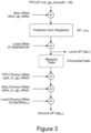
- the dequantization part is illustrated in Figure 2 .
- the scaling (or dequantization) process of VVC consists in scaling the transformed coefficients by a quantization step qStep and a quantization matrix m[][], resulting in dequantized coefficients d[][].
- d[ x ][ y ] Clip3( coeffMin, coeffMax, ( ( TransCoeffLevel[ xTbY ][ yTbY ][ cldx ][ x ][ y ] * m[ x ][ y ] * levelScale[ qP%6 ] ⁇ (qP / 6 ) ) + ( 1 ⁇ ( bdShift - 1 ) ) ) >> bdShift )
- Quantization control is the combination of syntax used to control the QP and quantization matrix for a specific coded block.
- a current coding scheme (VVC draft 6) describes a joint chroma coded residual feature, where a single chroma channel is coded, and Cb/Cr chroma channels are reconstructed by sign change (based on a slice-level flag) and/or 1 ⁇ 2 scale depending on joint chroma mode (TuCResMode), which is derived from the chroma transform blocks coded block flags tu_cbf_cb and tu_cbf_cr, as illustrated in Table 2: Table 2: Joint chroma coded modes in VVC draft 6 tu_cbf_cb tu_cbr_cr Reconstruction of Cb and Cr residuals TuCResMode Quant.
- the CSign variable of Table 2 is derived as ( 1 - 2 * pic_joint_cbcr_sign_flag ), where pic_joint_cbcr_sign_flag is a syntax element decoded at the picture level.
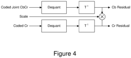
- the scaling and transformation process is adapted as illustrated in Figure 4 (and as specified in section 8.7.2 pp.282-283 of VVC draft 6, for example), where the single coded chroma block in dequantized, then inverse transformed, then split into Cb and Cr channels (called demultiplexing in the rest of this document).
- the "scale" factor is either -1, -1 ⁇ 2, +1 ⁇ 2 or +1 depending on CSign and TuCResMode, as detailed in Table 2.
- the grayed-out part normally for the secondary chroma channel, is not used in this case. Coded channel and Cb and Cr residuals can be swapped depending on joint chroma mode, which is not shown in Figure 4 for the sake of simplicity, but detailed in Table 2.
- Figure 5 shows the residual block decoding process as specified in a current coding scheme.
- the input to this process is a transform unit (TU) to decode, and the input bit-stream to parse.
- TU transform unit
- the embodiments presented here propose to move demultiplexing of Cb and Cr residuals from after transform to before dequantization, so that regular separate Cb and Cr chroma quantization control parameters (QP offsets, quantization matrices) can be used, without the need for specific joint-CbCr quantization control parameters.
- a current coding scheme includes specific quantization control parameters for joint chroma mode, but not for all parameters: there are no specific quantization matrices (Cb or Cr quantization matrix is selected as shown in Table 2).
- the problem to be solved is to make quantization control consistent for all chroma coding modes, either joint or not, while possibly removing joint chroma coding mode-specific quantization control parameters. This is expected to result in a simpler coding scheme and less coded bits.
- JVET-P0608 This has the drawback of adding more bits to the scaling_list_data syntax used to transmit custom quantization matrices.
- a second option proposed in JVET-P0608 that avoids transmitting extra quantization matrices, but still using specific ones for joint chroma coded blocks is to use an average of Cb and Cr quantization matrices.
- FAN K ET AL (BYTEDANCE): "Non-CE3: JCCR and LMCS interaction", 128. MPEG MEETING; 7-11 Oct. 2019; GENEVA; (MOTION PICTURE EXPERT GROUP OR ISO/ IEC JTC1/SC29/WG11), no. m50350 25 September 2019 ,
- LMCS Luma Mapping with Chroma Scaling
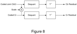
- Cb and Cr channels are demultiplexed before dequantization instead of after inverse transform.
- regular Cb and Cr quantization control parameters can be used, optionally with minor adjustments when the current block is joint-chroma coded (e.g. a general QP offset).
- Cb and Cr channels are reconstructed before dequantization instead of after inverse transform, as illustrated in Figure 8 .
- the algorithm of Figure 9 depicts the residual block decoding process according to the proposed embodiment.
- the process of Figure 9 is a modified version of the decoding process of a residual block of Figure 5 , according to the main embodiment of the proposed invention. As can be seen, the ordering of operations is changed compared to Figure 5 .
- the separate Cb and Cr residuals are now obtained in the quantized transform domain rather than in the spatial domain as is the case in VVC draft 6.
- the demultiplexing of the joint Cb/Cr quantized residual is performed first, in case the TU-level joint_cb_cr_residual_flag is true.
- the usual inverse quantization and inverse transform are applied separately on the obtained Cb and Cr residual blocks, exactly in the same way as for transform units not coded in joint Cb/Cr mode.
- Variants include moving the right shift of (1126) to:
- some specific quantization control parameters can be specified, e.g. the QP offset currently defined in VVC draft, like pps_joint_cbcr_qp_offset and/or slice_joint_cbcr_qp_offset, could still be used (either directly for Cb and Cr, or preferably on top of regular Cb and Cr QP offsets). This can be justified by specific properties of joint chroma coded blocks, like different scaling norm, or different visual quality.
- quantization control parameters specific to joint chroma coded blocks PPS and slice-level offset, chroma QP mapping table, etc
- VVC draft 6 quantization control parameters specific to joint chroma coded blocks (PPS and slice-level offset, chroma QP mapping table, etc) as defined by VVC draft 6 could still be used for both Cb and Cr channels instead of regular chroma QPs.
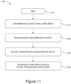
- FIG. 11 One embodiment of a method 1100 under the general aspects described here is shown in Figure 11 .
- the method commences at start block 1101 and control proceeds to block 1110 for demultiplexing Cb and Cr from a video block when joint Cb/Cr are coded for the video block.
- Control proceeds from block 1110 to block 1120 for dequantizing the demultiplexed Cb and Cr data.
- Control proceeds from block 1120 to block 1130 for inverse transforming the dequantized Cb and Cr data.
- Control proceeds from block 1130 to block 1140 for decoding said video block using said inverse transformed Cb and Cr data.
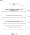
- FIG. 12 One embodiment of a method 1200 under the general aspects described here is shown in Figure 12 .
- the method commences at start block 1201 and control proceeds to block 1210 for parsing a video bitstream and scaling Cb and Cr from a video block.
- Control proceeds from block 1210 to block 1220 for dequantizing the demultiplexed Cb and Cr data.
- Control proceeds from block 1220 to block 1230 for inverse transforming the dequantized Cb and Cr data.
- Control proceeds from block 1230 to block 1240 for decoding said video block using said inverse transformed Cb and Cr data.
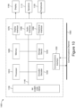
- Figure 13 shows one embodiment of an apparatus 1300 for encoding, decoding, compressing or decompressing video data using simplifications of coding modes based on neighboring samples dependent parametric models.
- the apparatus comprises Processor 1310 and can be interconnected to a memory 1320 through at least one port. Both Processor 1310 and memory 1320 can also have one or more additional interconnections to external connections.
- Processor 1310 is also configured to either insert or receive information in a bitstream and, either compressing, encoding or decoding using any of the described aspects.
- Figures 1 , 2 and 10 provide some embodiments, but other embodiments are contemplated and the discussion of Figures 1 , 2 and 10 does not limit the breadth of the implementations.
- At least one of the aspects generally relates to video encoding and decoding, and at least one other aspect generally relates to transmitting a bitstream generated or encoded.
- These and other aspects can be implemented as a method, an apparatus, a computer readable storage medium having stored thereon instructions for encoding or decoding video data according to any of the methods described, and/or a computer readable storage medium having stored thereon a bitstream generated according to any of the methods described.
- the terms “reconstructed” and “decoded” may be used interchangeably, the terms “pixel” and “sample” may be used interchangeably, the terms “image,” “picture” and “frame” may be used interchangeably.
- the term “reconstructed” is used at the encoder side while “decoded” is used at the decoder side.
- a picture is encoded by the encoder elements as described below.
- the picture to be encoded is partitioned (102) and processed in units of, for example, CUs.
- Each unit is encoded using, for example, either an intra or inter mode.
- intra prediction 160
- inter mode motion estimation (175) and compensation (170) are performed.
- the encoder decides (105) which one of the intra mode or inter mode to use for encoding the unit, and indicates the intra/inter decision by, for example, a prediction mode flag.
- Prediction residuals are calculated, for example, by subtracting (110) the predicted block from the original image block.
- the prediction residuals are then transformed (125) and quantized (130).
- the quantized transform coefficients, as well as motion vectors and other syntax elements, are entropy coded (145) to output a bitstream.
- the encoder can skip the transform and apply quantization directly to the non-transformed residual signal.
- the encoder can bypass both transform and quantization, i.e., the residual is coded directly without the application of the transform or quantization processes.
- the encoder decodes an encoded block to provide a reference for further predictions.
- the quantized transform coefficients are de-quantized (140) and inverse transformed (150) to decode prediction residuals.
- In-loop filters (165) are applied to the reconstructed picture to perform, for example, deblocking/SAO (Sample Adaptive Offset) filtering to reduce encoding artifacts.
- the filtered image is stored at a reference picture buffer (180).
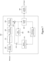
- Figure 2 illustrates a block diagram of a video decoder 200.
- a bitstream is decoded by the decoder elements as described below.
- Video decoder 200 generally performs a decoding pass reciprocal to the encoding pass as described in Figure 1 .
- the encoder 100 also generally performs video decoding as part of encoding video data.
- the input of the decoder includes a video bitstream, which can be generated by video encoder 100.
- the bitstream is first entropy decoded (230) to obtain transform coefficients, motion vectors, and other coded information.
- the picture partition information indicates how the picture is partitioned.
- the decoder may therefore divide (235) the picture according to the decoded picture partitioning information.
- the transform coefficients are de-quantized (240) and inverse transformed (250) to decode the prediction residuals.
- Combining (255) the decoded prediction residuals and the predicted block an image block is reconstructed.
- the predicted block can be obtained (270) from intra prediction (260) or motioncompensated prediction (i.e., inter prediction) (275).
- In-loop filters (265) are applied to the reconstructed image.
- the filtered image is stored at a reference picture buffer (280).
- the decoded picture can further go through post-decoding processing (285), for example, an inverse color transform (e.g. conversion from YCbCr 4:2:0 to RGB 4:4:4) or an inverse remapping performing the inverse of the remapping process performed in the pre-encoding processing (101).
- post-decoding processing can use metadata derived in the pre-encoding processing and signaled in the bitstream.
- FIG. 10 illustrates a block diagram of an example of a system in which various aspects and embodiments are implemented.
- System 1000 can be embodied as a device including the various components described below and is configured to perform one or more of the aspects described in this document. Examples of such devices include, but are not limited to, various electronic devices such as personal computers, laptop computers, smartphones, tablet computers, digital multimedia set top boxes, digital television receivers, personal video recording systems, connected home appliances, and servers.
- Elements of system 1000, singly or in combination can be embodied in a single integrated circuit (IC), multiple ICs, and/or discrete components.
- the processing and encoder/decoder elements of system 1000 are distributed across multiple ICs and/or discrete components.
- system 1000 is communicatively coupled to one or more other systems, or other electronic devices, via, for example, a communications bus or through dedicated input and/or output ports.
- system 1000 is configured to implement one or more of the aspects described in this document.
- the system 1000 includes at least one processor 1010 configured to execute instructions loaded therein for implementing, for example, the various aspects described in this document.
- Processor 1010 can include embedded memory, input output interface, and various other circuitries as known in the art.
- the system 1000 includes at least one memory 1020 (e.g., a volatile memory device, and/or a non-volatile memory device).
- System 1000 includes a storage device 1040, which can include non-volatile memory and/or volatile memory, including, but not limited to, Electrically Erasable Programmable Read-Only Memory (EEPROM), Read-Only Memory (ROM), Programmable Read-Only Memory (PROM), Random Access Memory (RAM), Dynamic Random Access Memory (DRAM), Static Random Access Memory (SRAM), flash, magnetic disk drive, and/or optical disk drive.
- the storage device 1040 can include an internal storage device, an attached storage device (including detachable and non-detachable storage devices), and/or a network accessible storage device, as non-limiting examples.
- processor 1010 Program code to be loaded onto processor 1010 or encoder/decoder 1030 to perform the various aspects described in this document can be stored in storage device 1040 and subsequently loaded onto memory 1020 for execution by processor 1010.
- processor 1010, memory 1020, storage device 1040, and encoder/decoder module 1030 can store one or more of various items during the performance of the processes described in this document.
- Such stored items can include, but are not limited to, the input video, the decoded video or portions of the decoded video, the bitstream, matrices, variables, and intermediate or final results from the processing of equations, formulas, operations, and operational logic.
- memory inside of the processor 1010 and/or the encoder/decoder module 1030 is used to store instructions and to provide working memory for processing that is needed during encoding or decoding.
- a memory external to the processing device (for example, the processing device can be either the processor 1010 or the encoder/decoder module 1030) is used for one or more of these functions.
- the external memory can be the memory 1020 and/or the storage device 1040, for example, a dynamic volatile memory and/or a non-volatile flash memory.
- an external non-volatile flash memory is used to store the operating system of, for example, a television.
- a fast external dynamic volatile memory such as a RAM is used as working memory for video coding and decoding operations, such as for MPEG-2 (MPEG refers to the Moving Picture Experts Group, MPEG-2 is also referred to as ISO/IEC 13818, and 13818-1 is also known as H.222, and 13818-2 is also known as H.262), HEVC (HEVC refers to High Efficiency Video Coding, also known as H.265 and MPEG-H Part 2), or VVC (Versatile Video Coding, a new standard being developed by JVET, the Joint Video Experts Team).
- MPEG-2 MPEG refers to the Moving Picture Experts Group
- MPEG-2 is also referred to as ISO/IEC 13818
- 13818-1 is also known as H.222
- 13818-2 is also known as H.262
- HEVC High Efficiency Video Coding
- VVC Very Video Coding
- the input devices of block 1130 have associated respective input processing elements as known in the art.
- the RF portion can be associated with elements suitable for (i) selecting a desired frequency (also referred to as selecting a signal, or band-limiting a signal to a band of frequencies), (ii) downconverting the selected signal, (iii) band-limiting again to a narrower band of frequencies to select (for example) a signal frequency band which can be referred to as a channel in certain embodiments, (iv) demodulating the downconverted and bandlimited signal, (v) performing error correction, and (vi) demultiplexing to select the desired stream of data packets.
- the RF portion of various embodiments includes one or more elements to perform these functions, for example, frequency selectors, signal selectors, band-limiters, channel selectors, filters, downconverters, demodulators, error correctors, and demultiplexers.
- the RF portion can include a tuner that performs various of these functions, including, for example, downconverting the received signal to a lower frequency (for example, an intermediate frequency or a near-baseband frequency) or to baseband.
- the RF portion and its associated input processing element receives an RF signal transmitted over a wired (for example, cable) medium, and performs frequency selection by filtering, downconverting, and filtering again to a desired frequency band.
- Adding elements can include inserting elements in between existing elements, such as, for example, inserting amplifiers and an analog-to-digital converter.
- the RF portion includes an antenna.
- USB and/or HDMI terminals can include respective interface processors for connecting system 1000 to other electronic devices across USB and/or HDMI connections.
- various aspects of input processing for example, Reed-Solomon error correction
- aspects of USB or HDMI interface processing can be implemented within separate interface ICs or within processor 1010 as necessary.
- the demodulated, error corrected, and demultiplexed stream is provided to various processing elements, including, for example, processor 1010, and encoder/decoder 1030 operating in combination with the memory and storage elements to process the datastream as necessary for presentation on an output device.
- Various elements of system 1000 can be provided within an integrated housing, Within the integrated housing, the various elements can be interconnected and transmit data therebetween using suitable connection arrangement, for example, an internal bus as known in the art, including the Inter-IC (I2C) bus, wiring, and printed circuit boards.
- I2C Inter-IC
- the system 1000 includes communication interface 1050 that enables communication with other devices via communication channel 1060.
- the communication interface 1050 can include, but is not limited to, a transceiver configured to transmit and to receive data over communication channel 1060.
- the communication interface 1050 can include, but is not limited to, a modem or network card and the communication channel 1060 can be implemented, for example, within a wired and/or a wireless medium.
- Wi-Fi Wireless Fidelity
- IEEE 802.11 IEEE refers to the Institute of Electrical and Electronics Engineers
- the Wi-Fi signal of these embodiments is received over the communications channel 1060 and the communications interface 1050 which are adapted for Wi-Fi communications.
- the communications channel 1060 of these embodiments is typically connected to an access point or router that provides access to external networks including the Internet for allowing streaming applications and other over-the-top communications.
- Other embodiments provide streamed data to the system 1000 using a set-top box that delivers the data over the HDMI connection of the input block 1130.
- Still other embodiments provide streamed data to the system 1000 using the RF connection of the input block 1130.
- various embodiments provide data in a nonstreaming manner.
- various embodiments use wireless networks other than Wi-Fi, for example a cellular network or a Bluetooth network.
- the system 1000 can provide an output signal to various output devices, including a display 1100, speakers 1110, and other peripheral devices 1120.
- the display 1100 of various embodiments includes one or more of, for example, a touchscreen display, an organic light-emitting diode (OLED) display, a curved display, and/or a foldable display.
- the display 1100 can be for a television, a tablet, a laptop, a cell phone (mobile phone), or other device.
- the display 1100 can also be integrated with other components (for example, as in a smart phone), or separate (for example, an external monitor for a laptop).
- control signals are communicated between the system 1000 and the display 1100, speakers 1110, or other peripheral devices 1120 using signaling such as AV.Link, Consumer Electronics Control (CEC), or other communications protocols that enable device-to-device control with or without user intervention.
- the output devices can be communicatively coupled to system 1000 via dedicated connections through respective interfaces 1070, 1080, and 1090. Alternatively, the output devices can be connected to system 1000 using the communications channel 1060 via the communications interface 1050.
- the display 1100 and speakers 1110 can be integrated in a single unit with the other components of system 1000 in an electronic device such as, for example, a television.
- the display interface 1070 includes a display driver, such as, for example, a timing controller (T Con) chip.
- the display 1100 and speaker 1110 can alternatively be separate from one or more of the other components, for example, if the RF portion of input 1130 is part of a separate set-top box.
- the output signal can be provided via dedicated output connections, including, for example, HDMI ports, USB ports, or COMP outputs.
- the embodiments can be carried out by computer software implemented by the processor 1010 or by hardware, or by a combination of hardware and software. As a non-limiting example, the embodiments can be implemented by one or more integrated circuits.
- the memory 1020 can be of any type appropriate to the technical environment and can be implemented using any appropriate data storage technology, such as optical memory devices, magnetic memory devices, semiconductor-based memory devices, fixed memory, and removable memory, as non-limiting examples.
- the processor 1010 can be of any type appropriate to the technical environment, and can encompass one or more of microprocessors, general purpose computers, special purpose computers, and processors based on a multi-core architecture, as non-limiting examples.
- Decoding can encompass all or part of the processes performed, for example, on a received encoded sequence to produce a final output suitable for display.
- processes include one or more of the processes typically performed by a decoder, for example, entropy decoding, inverse quantization, inverse transformation, and differential decoding.
- processes also, or alternatively, include processes performed by a decoder of various implementations described in this application.
- decoding refers only to entropy decoding
- decoding refers only to differential decoding
- decoding refers to a combination of entropy decoding and differential decoding.
- encoding can encompass all or part of the processes performed, for example, on an input video sequence to produce an encoded bitstream.
- processes include one or more of the processes typically performed by an encoder, for example, partitioning, differential encoding, transformation, quantization, and entropy encoding.
- processes also, or alternatively, include processes performed by an encoder of various implementations described in this application.
- encoding refers only to entropy encoding
- encoding refers only to differential encoding
- encoding refers to a combination of differential encoding and entropy encoding.
- syntax elements as used herein are descriptive terms. As such, they do not preclude the use of other syntax element names.
- Various embodiments may refer to parametric models or rate distortion optimization.
- the balance or trade-off between the rate and distortion is usually considered, often given the constraints of computational complexity. It can be measured through a Rate Distortion Optimization (RDO) metric, or through Least Mean Square (LMS), Mean of Absolute Errors (MAE), or other such measurements.
- RDO Rate Distortion Optimization
- LMS Least Mean Square
- MAE Mean of Absolute Errors
- Rate distortion optimization is usually formulated as minimizing a rate distortion function, which is a weighted sum of the rate and of the distortion. There are different approaches to solve the rate distortion optimization problem.
- the approaches may be based on an extensive testing of all encoding options, including all considered modes or coding parameters values, with a complete evaluation of their coding cost and related distortion of the reconstructed signal after coding and decoding.
- Faster approaches may also be used, to save encoding complexity, in particular with computation of an approximated distortion based on the prediction or the prediction residual signal, not the reconstructed one.
- Mix of these two approaches can also be used, such as by using an approximated distortion for only some of the possible encoding options, and a complete distortion for other encoding options.
- Other approaches only evaluate a subset of the possible encoding options. More generally, many approaches employ any of a variety of techniques to perform the optimization, but the optimization is not necessarily a complete evaluation of both the coding cost and related distortion.
- the implementations and aspects described herein can be implemented in, for example, a method or a process, an apparatus, a software program, a data stream, or a signal. Even if only discussed in the context of a single form of implementation (for example, discussed only as a method), the implementation of features discussed can also be implemented in other forms (for example, an apparatus or program).
- An apparatus can be implemented in, for example, appropriate hardware, software, and firmware.
- the methods can be implemented in, for example, , a processor, which refers to processing devices in general, including, for example, a computer, a microprocessor, an integrated circuit, or a programmable logic device. Processors also include communication devices, such as, for example, computers, cell phones, portable/personal digital assistants ("PDAs”), and other devices that facilitate communication of information between end-users.
- PDAs portable/personal digital assistants
- references to "one embodiment” or “an embodiment” or “one implementation” or “an implementation”, as well as other variations thereof, means that a particular feature, structure, characteristic, and so forth described in connection with the embodiment is included in at least one embodiment.
- the appearances of the phrase “in one embodiment” or “in an embodiment” or “in one implementation” or “in an implementation”, as well any other variations, appearing in various places throughout this application are not necessarily all referring to the same embodiment.
- Determining the information can include one or more of, for example, estimating the information, calculating the information, predicting the information, or retrieving the information from memory.
- Accessing the information can include one or more of, for example, receiving the information, retrieving the information (for example, from memory), storing the information, moving the information, copying the information, calculating the information, determining the information, predicting the information, or estimating the information.
- this application may refer to "receiving" various pieces of information.
- Receiving is, as with “accessing”, intended to be a broad term.
- Receiving the information can include one or more of, for example, accessing the information, or retrieving the information (for example, from memory).
- “receiving” is typically involved, in one way or another, during operations such as, for example, storing the information, processing the information, transmitting the information, moving the information, copying the information, erasing the information, calculating the information, determining the information, predicting the information, or estimating the information.
- such phrasing is intended to encompass the selection of the first listed option (A) only, or the selection of the second listed option (B) only, or the selection of the third listed option (C) only, or the selection of the first and the second listed options (A and B) only, or the selection of the first and third listed options (A and C) only, or the selection of the second and third listed options (B and C) only, or the selection of all three options (A and B and C).
- This may be extended, as is clear to one of ordinary skill in this and related arts, for as many items as are listed.
- the word "signal" refers to, among other things, indicating something to a corresponding decoder.
- the encoder signals a particular one of a plurality of transforms, coding modes or flags.
- the same transform, parameter, or mode is used at both the encoder side and the decoder side.
- an encoder can transmit (explicit signaling) a particular parameter to the decoder so that the decoder can use the same particular parameter.
- signaling can be used without transmitting (implicit signaling) to simply allow the decoder to know and select the particular parameter.
- implementations can produce a variety of signals formatted to carry information that can be, for example, stored or transmitted.
- the information can include, for example, instructions for performing a method, or data produced by one of the described implementations.
- a signal can be formatted to carry the bitstream of a described embodiment.
- Such a signal can be formatted, for example, as an electromagnetic wave (for example, using a radio frequency portion of spectrum) or as a baseband signal.
- the formatting can include, for example, encoding a data stream and modulating a carrier with the encoded data stream.
- the information that the signal carries can be, for example, analog or digital information.
- the signal can be transmitted over a variety of different wired or wireless links, as is known.
- the signal can be stored on a processor-readable medium.
- embodiments across various claim categories and types. Features of these embodiments can be provided alone or in any combination. Further, embodiments can include one or more of the following features, devices, or aspects, alone or in any combination, across various claim categories and types:
Landscapes
- Engineering & Computer Science (AREA)
- Multimedia (AREA)
- Signal Processing (AREA)
- Physics & Mathematics (AREA)
- Discrete Mathematics (AREA)
- General Physics & Mathematics (AREA)
- Compression Or Coding Systems Of Tv Signals (AREA)
- Color Television Systems (AREA)
Claims (7)
- Verfahren, umfassend:Demultiplexieren gemeinsamer Cb/Cr-quantisierter Residuen von einem Videoblock, wenn für den Videoblock ein gemeinsamer Chroma-Coding-Modus verwendet wird;Dequantisieren der demultiplexierten Cb- und Cr-Daten;inverses Transformieren der dequantisierten Cb- und Cr-Daten; undDecodieren des genannten Videoblocks unter Verwendung der genannten invers transformierten Cb- und Cr-Daten.
- Apparatur, umfassend:
einen Prozessor, dafür konfiguriert:gemeinsame Cb/Cr-quantisierte Residuen von einem Videoblock zu demultiplexieren, wenn für den Videoblock ein gemeinsamer Chroma-Coding-Modus verwendet wird;die demultiplexierten Cb- und Cr-Daten zu dequantisieren;die dequantisierten Cb- und Cr-Daten invers zu transformieren; undden genannten Videoblock unter Verwendung der genannten invers transformierten Cb- und Cr-Daten zu decodieren. - Vorrichtung, umfassend:eine Apparatur nach Anspruch 1; undmindestens eins von (i) einer Antenne, die dafür konfiguriert ist, ein Signal zu empfangen, wobei das Signal den Videoblock umfasst, (ii) einen Band Limiter, der dafür konfiguriert ist, das empfangene Signal auf ein Band von Frequenzen, das den Videoblock enthält, zu begrenzen, und (iii) ein Display, das dafür konfiguriert ist, einen Output darzustellen, der einen Videoblock repräsentiert.
- Verfahren nach Anspruch 1 oder Apparatur nach Anspruch 2, wobei separate Cb- und Cr-Chroma-Quantisierungssteuerparameter spezifiziert sind.
- Verfahren nach Anspruch 4 oder Apparatur nach Anspruch 4, wobei Cb- und Cr-QP-Offsets für gemeinsame Chroma-codierte Blöcke spezifiziert sind.
- Verfahren nach Anspruch 1 oder Apparatur nach Anspruch 2, wobei Quantisierungssteuerparameter, die für gemeinsame Chroma-codierte Blöcke spezifisch sind, für beide Cb- und Cr-Kanäle verwendet werden, anstelle gemeinsamer Cb/Cr-Quantisierungssteuerparameter.
- Computerprogrammprodukt, das Anweisungen umfasst, die bei Ausführung des Programms durch einen Computer den Computer veranlassen, das Verfahren nach Anspruch 1 durchzuführen.
Applications Claiming Priority (2)
| Application Number | Priority Date | Filing Date | Title |
|---|---|---|---|
| EP19306586 | 2019-12-06 | ||
| PCT/EP2020/084021 WO2021110628A1 (en) | 2019-12-06 | 2020-12-01 | Scaling process for joint chroma coded blocks |
Publications (2)
| Publication Number | Publication Date |
|---|---|
| EP4070547A1 EP4070547A1 (de) | 2022-10-12 |
| EP4070547B1 true EP4070547B1 (de) | 2025-07-02 |
Family
ID=69005653
Family Applications (1)
| Application Number | Title | Priority Date | Filing Date |
|---|---|---|---|
| EP20812087.3A Active EP4070547B1 (de) | 2019-12-06 | 2020-12-01 | Skalierungsverfahren für gemeinsame chroma-codierte blöcke |
Country Status (5)
| Country | Link |
|---|---|
| US (1) | US12081798B2 (de) |
| EP (1) | EP4070547B1 (de) |
| JP (1) | JP7677970B2 (de) |
| CN (1) | CN115336267B (de) |
| WO (1) | WO2021110628A1 (de) |
Families Citing this family (2)
| Publication number | Priority date | Publication date | Assignee | Title |
|---|---|---|---|---|
| US11616983B2 (en) * | 2020-05-05 | 2023-03-28 | Tencent America LLC | Joint component secondary transform |
| US20250350725A1 (en) * | 2023-04-23 | 2025-11-13 | Quasistatics Inc. | Method and system for energy-efficient approximate digital jpeg and mjpeg-compression |
Family Cites Families (8)
| Publication number | Priority date | Publication date | Assignee | Title |
|---|---|---|---|---|
| US7599438B2 (en) * | 2003-09-07 | 2009-10-06 | Microsoft Corporation | Motion vector block pattern coding and decoding |
| CN106162185B (zh) * | 2012-01-20 | 2019-10-18 | 维洛媒体国际有限公司 | 色度量化参数扩展 |
| EP2843949B1 (de) * | 2013-06-28 | 2020-04-29 | Velos Media International Limited | Verfahren und Vorrichtungen zur Emulation von Low-Fidelity-Kodierung in einem High-Fidelity-Kodierer |
| US10523966B2 (en) * | 2017-03-31 | 2019-12-31 | Mediatek Inc. | Coding transform blocks |
| KR20240144474A (ko) * | 2018-03-30 | 2024-10-02 | 인터디지털 브이씨 홀딩스 인코포레이티드 | 비디오 인코딩 및 디코딩에서의 크로마 양자화 파라미터 조정 |
| CN110009725B (zh) * | 2019-03-06 | 2021-04-09 | 浙江大学 | 基于多张rgb图像的人脸重建方法 |
| JP7493310B2 (ja) * | 2019-06-07 | 2024-05-31 | キヤノン株式会社 | 画像復号装置及び方法及びプログラム |
| CN120223888A (zh) * | 2019-07-05 | 2025-06-27 | Lg 电子株式会社 | 图像解码方法及其设备 |
-
2020
- 2020-12-01 EP EP20812087.3A patent/EP4070547B1/de active Active
- 2020-12-01 WO PCT/EP2020/084021 patent/WO2021110628A1/en not_active Ceased
- 2020-12-01 US US17/782,226 patent/US12081798B2/en active Active
- 2020-12-01 JP JP2022529701A patent/JP7677970B2/ja active Active
- 2020-12-01 CN CN202080079424.5A patent/CN115336267B/zh active Active
Also Published As
| Publication number | Publication date |
|---|---|
| JP7677970B2 (ja) | 2025-05-15 |
| JP2023504372A (ja) | 2023-02-03 |
| EP4070547A1 (de) | 2022-10-12 |
| WO2021110628A1 (en) | 2021-06-10 |
| US12081798B2 (en) | 2024-09-03 |
| CN115336267A (zh) | 2022-11-11 |
| CN115336267B (zh) | 2024-12-31 |
| US20230232045A1 (en) | 2023-07-20 |
Similar Documents
| Publication | Publication Date | Title |
|---|---|---|
| US12413729B2 (en) | Chroma quantization parameter adjustment in video encoding and decoding | |
| IL317810A (en) | Simplifications of coding modes based on neighboring examples depend on parametric models | |
| US12170771B2 (en) | Single-index quantization matrix design for video encoding and decoding | |
| US12177446B2 (en) | Method and apparatus for determining chroma quantization parameters when using separate coding trees for luma and chroma | |
| US20240171756A1 (en) | Template matching prediction for video encoding and decoding | |
| US12081798B2 (en) | Scaling process for joint chroma coded blocks | |
| US11979585B2 (en) | Current picture referencing block vector initialization with dual tree | |
| WO2021122416A1 (en) | Subblock merge candidates in triangle merge mode | |
| EP3709647A1 (de) | Transformationsauswahl und signalisierung zur videocodierung oder -decodierung | |
| US12401790B2 (en) | Combining ABT with VVC sub-block-based coding tools | |
| US20220360781A1 (en) | Video encoding and decoding using block area based quantization matrices | |
| US20230262268A1 (en) | Chroma format dependent quantization matrices for video encoding and decoding | |
| EP3641312A1 (de) | Verfahren und vorrichtung zur bestimmung von chromaquantisierungsparametern bei getrennten codierungsbäumen für luma und chroma | |
| WO2020068461A1 (en) | Separate coding trees for luma and chroma prediction | |
| US20220224902A1 (en) | Quantization matrices selection for separate color plane mode | |
| CN117501692A (zh) | 用于视频编码和解码的模板匹配预测 |
Legal Events
| Date | Code | Title | Description |
|---|---|---|---|
| STAA | Information on the status of an ep patent application or granted ep patent |
Free format text: STATUS: UNKNOWN |
|
| STAA | Information on the status of an ep patent application or granted ep patent |
Free format text: STATUS: THE INTERNATIONAL PUBLICATION HAS BEEN MADE |
|
| PUAI | Public reference made under article 153(3) epc to a published international application that has entered the european phase |
Free format text: ORIGINAL CODE: 0009012 |
|
| STAA | Information on the status of an ep patent application or granted ep patent |
Free format text: STATUS: REQUEST FOR EXAMINATION WAS MADE |
|
| 17P | Request for examination filed |
Effective date: 20220704 |
|
| AK | Designated contracting states |
Kind code of ref document: A1 Designated state(s): AL AT BE BG CH CY CZ DE DK EE ES FI FR GB GR HR HU IE IS IT LI LT LU LV MC MK MT NL NO PL PT RO RS SE SI SK SM TR |
|
| DAV | Request for validation of the european patent (deleted) | ||
| DAX | Request for extension of the european patent (deleted) | ||
| RAP1 | Party data changed (applicant data changed or rights of an application transferred) |
Owner name: INTERDIGITAL CE PATENT HOLDINGS, SAS |
|
| GRAP | Despatch of communication of intention to grant a patent |
Free format text: ORIGINAL CODE: EPIDOSNIGR1 |
|
| STAA | Information on the status of an ep patent application or granted ep patent |
Free format text: STATUS: GRANT OF PATENT IS INTENDED |
|
| INTG | Intention to grant announced |
Effective date: 20250123 |
|
| GRAS | Grant fee paid |
Free format text: ORIGINAL CODE: EPIDOSNIGR3 |
|
| GRAA | (expected) grant |
Free format text: ORIGINAL CODE: 0009210 |
|
| STAA | Information on the status of an ep patent application or granted ep patent |
Free format text: STATUS: THE PATENT HAS BEEN GRANTED |
|
| P01 | Opt-out of the competence of the unified patent court (upc) registered |
Free format text: CASE NUMBER: APP_22702/2025 Effective date: 20250513 |
|
| AK | Designated contracting states |
Kind code of ref document: B1 Designated state(s): AL AT BE BG CH CY CZ DE DK EE ES FI FR GB GR HR HU IE IS IT LI LT LU LV MC MK MT NL NO PL PT RO RS SE SI SK SM TR |
|
| REG | Reference to a national code |
Ref country code: GB Ref legal event code: FG4D |
|
| REG | Reference to a national code |
Ref country code: CH Ref legal event code: EP |
|
| REG | Reference to a national code |
Ref country code: DE Ref legal event code: R096 Ref document number: 602020053917 Country of ref document: DE |
|
| REG | Reference to a national code |
Ref country code: IE Ref legal event code: FG4D |
|
| REG | Reference to a national code |
Ref country code: NL Ref legal event code: FP |
|
| PG25 | Lapsed in a contracting state [announced via postgrant information from national office to epo] |
Ref country code: PT Free format text: LAPSE BECAUSE OF FAILURE TO SUBMIT A TRANSLATION OF THE DESCRIPTION OR TO PAY THE FEE WITHIN THE PRESCRIBED TIME-LIMIT Effective date: 20251103 |
|
| REG | Reference to a national code |
Ref country code: AT Ref legal event code: MK05 Ref document number: 1810631 Country of ref document: AT Kind code of ref document: T Effective date: 20250702 |
|
| PG25 | Lapsed in a contracting state [announced via postgrant information from national office to epo] |
Ref country code: IS Free format text: LAPSE BECAUSE OF FAILURE TO SUBMIT A TRANSLATION OF THE DESCRIPTION OR TO PAY THE FEE WITHIN THE PRESCRIBED TIME-LIMIT Effective date: 20251102 |
|
| PGFP | Annual fee paid to national office [announced via postgrant information from national office to epo] |
Ref country code: GB Payment date: 20251223 Year of fee payment: 6 |
|
| PG25 | Lapsed in a contracting state [announced via postgrant information from national office to epo] |
Ref country code: NO Free format text: LAPSE BECAUSE OF FAILURE TO SUBMIT A TRANSLATION OF THE DESCRIPTION OR TO PAY THE FEE WITHIN THE PRESCRIBED TIME-LIMIT Effective date: 20251002 |
|
| REG | Reference to a national code |
Ref country code: LT Ref legal event code: MG9D |
|
| PG25 | Lapsed in a contracting state [announced via postgrant information from national office to epo] |
Ref country code: AT Free format text: LAPSE BECAUSE OF FAILURE TO SUBMIT A TRANSLATION OF THE DESCRIPTION OR TO PAY THE FEE WITHIN THE PRESCRIBED TIME-LIMIT Effective date: 20250702 |
|
| PG25 | Lapsed in a contracting state [announced via postgrant information from national office to epo] |
Ref country code: FI Free format text: LAPSE BECAUSE OF FAILURE TO SUBMIT A TRANSLATION OF THE DESCRIPTION OR TO PAY THE FEE WITHIN THE PRESCRIBED TIME-LIMIT Effective date: 20250702 |
|
| PG25 | Lapsed in a contracting state [announced via postgrant information from national office to epo] |
Ref country code: HR Free format text: LAPSE BECAUSE OF FAILURE TO SUBMIT A TRANSLATION OF THE DESCRIPTION OR TO PAY THE FEE WITHIN THE PRESCRIBED TIME-LIMIT Effective date: 20250702 |
|
| PGFP | Annual fee paid to national office [announced via postgrant information from national office to epo] |
Ref country code: FR Payment date: 20251223 Year of fee payment: 6 Ref country code: NL Payment date: 20251222 Year of fee payment: 6 |
|
| PG25 | Lapsed in a contracting state [announced via postgrant information from national office to epo] |
Ref country code: GR Free format text: LAPSE BECAUSE OF FAILURE TO SUBMIT A TRANSLATION OF THE DESCRIPTION OR TO PAY THE FEE WITHIN THE PRESCRIBED TIME-LIMIT Effective date: 20251003 |
|
| PG25 | Lapsed in a contracting state [announced via postgrant information from national office to epo] |
Ref country code: CZ Free format text: LAPSE BECAUSE OF FAILURE TO SUBMIT A TRANSLATION OF THE DESCRIPTION OR TO PAY THE FEE WITHIN THE PRESCRIBED TIME-LIMIT Effective date: 20250702 Ref country code: SE Free format text: LAPSE BECAUSE OF FAILURE TO SUBMIT A TRANSLATION OF THE DESCRIPTION OR TO PAY THE FEE WITHIN THE PRESCRIBED TIME-LIMIT Effective date: 20250702 |
|
| PG25 | Lapsed in a contracting state [announced via postgrant information from national office to epo] |
Ref country code: LV Free format text: LAPSE BECAUSE OF FAILURE TO SUBMIT A TRANSLATION OF THE DESCRIPTION OR TO PAY THE FEE WITHIN THE PRESCRIBED TIME-LIMIT Effective date: 20250702 |
|
| PG25 | Lapsed in a contracting state [announced via postgrant information from national office to epo] |
Ref country code: PL Free format text: LAPSE BECAUSE OF FAILURE TO SUBMIT A TRANSLATION OF THE DESCRIPTION OR TO PAY THE FEE WITHIN THE PRESCRIBED TIME-LIMIT Effective date: 20250702 Ref country code: BG Free format text: LAPSE BECAUSE OF FAILURE TO SUBMIT A TRANSLATION OF THE DESCRIPTION OR TO PAY THE FEE WITHIN THE PRESCRIBED TIME-LIMIT Effective date: 20250702 |
|
| PG25 | Lapsed in a contracting state [announced via postgrant information from national office to epo] |
Ref country code: RS Free format text: LAPSE BECAUSE OF FAILURE TO SUBMIT A TRANSLATION OF THE DESCRIPTION OR TO PAY THE FEE WITHIN THE PRESCRIBED TIME-LIMIT Effective date: 20251002 |
|
| PG25 | Lapsed in a contracting state [announced via postgrant information from national office to epo] |
Ref country code: ES Free format text: LAPSE BECAUSE OF FAILURE TO SUBMIT A TRANSLATION OF THE DESCRIPTION OR TO PAY THE FEE WITHIN THE PRESCRIBED TIME-LIMIT Effective date: 20250702 |
|
| PG25 | Lapsed in a contracting state [announced via postgrant information from national office to epo] |
Ref country code: RO Free format text: LAPSE BECAUSE OF FAILURE TO SUBMIT A TRANSLATION OF THE DESCRIPTION OR TO PAY THE FEE WITHIN THE PRESCRIBED TIME-LIMIT Effective date: 20250702 |
|
| PG25 | Lapsed in a contracting state [announced via postgrant information from national office to epo] |
Ref country code: SM Free format text: LAPSE BECAUSE OF FAILURE TO SUBMIT A TRANSLATION OF THE DESCRIPTION OR TO PAY THE FEE WITHIN THE PRESCRIBED TIME-LIMIT Effective date: 20250702 |
|
| PG25 | Lapsed in a contracting state [announced via postgrant information from national office to epo] |
Ref country code: DK Free format text: LAPSE BECAUSE OF FAILURE TO SUBMIT A TRANSLATION OF THE DESCRIPTION OR TO PAY THE FEE WITHIN THE PRESCRIBED TIME-LIMIT Effective date: 20250702 |
|
| PGFP | Annual fee paid to national office [announced via postgrant information from national office to epo] |
Ref country code: DE Payment date: 20251229 Year of fee payment: 6 |
|
| PG25 | Lapsed in a contracting state [announced via postgrant information from national office to epo] |
Ref country code: IT Free format text: LAPSE BECAUSE OF FAILURE TO SUBMIT A TRANSLATION OF THE DESCRIPTION OR TO PAY THE FEE WITHIN THE PRESCRIBED TIME-LIMIT Effective date: 20250702 |
|
| PG25 | Lapsed in a contracting state [announced via postgrant information from national office to epo] |
Ref country code: SK Free format text: LAPSE BECAUSE OF FAILURE TO SUBMIT A TRANSLATION OF THE DESCRIPTION OR TO PAY THE FEE WITHIN THE PRESCRIBED TIME-LIMIT Effective date: 20250702 Ref country code: EE Free format text: LAPSE BECAUSE OF FAILURE TO SUBMIT A TRANSLATION OF THE DESCRIPTION OR TO PAY THE FEE WITHIN THE PRESCRIBED TIME-LIMIT Effective date: 20250702 |
|
| PLBE | No opposition filed within time limit |
Free format text: ORIGINAL CODE: 0009261 |
|
| STAA | Information on the status of an ep patent application or granted ep patent |
Free format text: STATUS: NO OPPOSITION FILED WITHIN TIME LIMIT |