EP4070519B1 - Verfahren, computerprogramm und system zur gemeinsamen nutzung von daten zur gemeinsamen nutzung benutzerspezifischer daten eines benutzers - Google Patents
Verfahren, computerprogramm und system zur gemeinsamen nutzung von daten zur gemeinsamen nutzung benutzerspezifischer daten eines benutzers Download PDFInfo
- Publication number
- EP4070519B1 EP4070519B1 EP20807817.0A EP20807817A EP4070519B1 EP 4070519 B1 EP4070519 B1 EP 4070519B1 EP 20807817 A EP20807817 A EP 20807817A EP 4070519 B1 EP4070519 B1 EP 4070519B1
- Authority
- EP
- European Patent Office
- Prior art keywords
- user
- data
- processing circuitry
- data processing
- access rights
- Prior art date
- Legal status (The legal status is an assumption and is not a legal conclusion. Google has not performed a legal analysis and makes no representation as to the accuracy of the status listed.)
- Active
Links
Images










Classifications
-
- H—ELECTRICITY
- H04—ELECTRIC COMMUNICATION TECHNIQUE
- H04L—TRANSMISSION OF DIGITAL INFORMATION, e.g. TELEGRAPHIC COMMUNICATION
- H04L63/00—Network architectures or network communication protocols for network security
- H04L63/10—Network architectures or network communication protocols for network security for controlling access to devices or network resources
-
- G—PHYSICS
- G06—COMPUTING OR CALCULATING; COUNTING
- G06F—ELECTRIC DIGITAL DATA PROCESSING
- G06F21/00—Security arrangements for protecting computers, components thereof, programs or data against unauthorised activity
- G06F21/60—Protecting data
- G06F21/62—Protecting access to data via a platform, e.g. using keys or access control rules
- G06F21/6218—Protecting access to data via a platform, e.g. using keys or access control rules to a system of files or objects, e.g. local or distributed file system or database
- G06F21/6245—Protecting personal data, e.g. for financial or medical purposes
-
- G—PHYSICS
- G06—COMPUTING OR CALCULATING; COUNTING
- G06F—ELECTRIC DIGITAL DATA PROCESSING
- G06F21/00—Security arrangements for protecting computers, components thereof, programs or data against unauthorised activity
- G06F21/60—Protecting data
- G06F21/64—Protecting data integrity, e.g. using checksums, certificates or signatures
Definitions
- Embodiments of the present disclosure relate to a method, a computer program, a system and apparatuses for sharing user-specific data of a user. Particularly, the examples relate to a concept for controlling a communication of the user-specific data to an external entity.
- the user/customer may not have any control, clarity and/or ownership of the user-specific data.
- Document CN109326337A relates to an improved stock authorization certification mechanism DPOS, smart contract, cloud storage and interceptable signature technology, in particular to a model and method for storing and sharing electronic medical records based on blockchain which can be used for secure storage and sharing of data under blockchain technology.
- the user may have a permanent access to the access rights, for example, to modify or check the access rights which enables the user to control sharing the user-specific data among diverse external entities.
- the first data processing circuitry comprises a data storage.
- the data storage can be implemented as a cloud storage (e.g. InterPlanetary File System (IPFS), Sia or StorJ) accessible via the internet or alternatively as a "local" data storage, such as a hard disk drive, a Read Only Memory (ROM) or comparable electro-mechanical data storage devices.
- IPFS InterPlanetary File System
- Sia Sia
- StorJ StorJ
- a "local" data storage such as a hard disk drive, a Read Only Memory (ROM) or comparable electro-mechanical data storage devices.
- the second data processing circuitry may be separated from the first data processing circuitry.
- the second data processing circuitry may, similar to the first data processing circuitry, comprise another data storage which can be implemented as another cloud storage comprising multiple interconnected data servers. Alternatively, the second data processing circuitry can comprise another "local" data storage.
- the access rights can be stored on the cloud storage of the second data processing circuitry.
- the access rights of different external entities can be different.
- the portion of the user-specific data which is accessible to the different entities may be different.
- the interface between the first and the second data processing circuitry comprises a physical link to communicate the access rights to the first data processing circuitry.
- the physical link can comprise one or more radio communication links and/or wired links which each individually or in combination may form a network path between the first and the second data processing circuitry.
- the user interface may comprise an input device and optionally a user software, such as an application programming interface (API) implemented on the input device.
- the input device can be configured to establish a (data) connection to the second data processing circuitry to authenticate the user to whom the user-specific data belongs.
- the input device can execute an authentication process using a user-specific input (e.g. fingerprint, credentials and/or facial recognition).
- the user can modify the access rights, e.g. extend or restrict the access rights for the external entity.
- the user can control sharing the user-specific data among the external entities by modifying the access rights. Further, the user is able to restrict or revoke access rights of one of the external entities.
- the user interface is configured to provide user-specific credentials to the second data processing circuitry to authenticate the user.
- the credentials for example, comprise a user-specific input (e.g. fingerprint, credentials and/or facial recognition).
- a user-specific input e.g. fingerprint, credentials and/or facial recognition
- the second data processing circuitry may verify the user-specific credentials through a comparison with reference data, for example, indicative of a password or image data related to a face of the user.
- This enables the user to authenticate himself independently of the input device utilized as user interface.
- the user owns multiple input devices (e.g. a mobile, a tablet and a personal computer).
- the user can authenticate himself regardless of which of the input device he is using with the user-specific credentials.
- the second data processing circuitry is further configured to store ownership rights of the user to modify the access rights.
- the second data processing circuitry is further configured to store the access rights and the ownership rights on a blockchain.
- the blockchain can be understood as a (growing) list of records, called blocks, which are linked using cryptographic functions. For purposes of auditability, each block contains a cryptographic hash of the previous block and a timestamp.
- At least one of the blocks may further contain the access rights.
- the blockchain can be shared within the multiple interconnected data servers (e.g. of a distributed ledger) of the second data processing circuitry.
- storing the access rights on a blockchain may enable the user to audit preceding modifications and invocations of the access rights.
- the first data processing circuitry is further configured to combine the blockchain with access information on communicating the portion of the user-specific data to the external entity.
- the first data processing circuitry logs in the form of the access information at which time which one of the different external entities had access to which portion of the user-specific data.
- the second data processing circuitry is further configured to store a first cryptographic accumulator defined for the ownership rights and a second cryptographic accumulator defined for the access rights.
- the first cryptographic accumulator may accumulate one or more first members indicative of the ownership rights and the second cryptographic accumulator may accumulate one or more second members indicative of the access rights.
- a cryptographic accumulator can be understood as a membership function which allows to verify if an input of the membership function is a member (e.g. a prime number or a hash) of the cryptographic accumulator without revealing every member included.
- the access rights and/or the ownership rights can be reflected by so-called “commitments” according to a cryptographic primitive called “commitment scheme".
- the skilled person having benefit from the present disclosure will appreciate that alternatively the commitments of the access rights and/or the ownership rights can be stored in cryptographic accumulators, such as Merkle trees/hash trees.
- the first and the second cryptographic accumulator can be stored on the blockchain.
- the user interface is further configured to provide to the second data processing circuitry a first zero knowledge proof.
- the first cryptographic accumulator can be configured to authenticate the user by verifying that a user-specific input of the first zero knowledge proof corresponds to at least one of the first members accumulated by the first cryptographic accumulator.
- a zero knowledge proof or zero knowledge protocol is a method by which a prover can prove to a verifier that they know an information, without revealing the information to the verifier.
- the zero knowledge proof can be generated using a predefined proving logic and the information as input. Subsequently, the zero knowledge proof can be verified using a predefined verifying logic associated with the proving logic.
- the user proves a knowledge on the user-specific input indicative of the ownership rights using the first zero knowledge proof.
- the user-specific input may comprise one or more commitments associated with the ownership rights of the user.
- the first cryptographic accumulator may be a one way membership function and may calculate an accumulated value from the first members.
- the first cryptographic accumulator may verify if the user-specific input of the first zero knowledge proof is one of the first members accumulated by the first accumulator.
- the first cryptographic accumulator verifies whether the user specific input corresponds to a (prime) factor of the accumulated value.
- the second data processing circuitry can determine the ownership rights of the user from the corresponding first members without the user being required to reveal his identity publicly.
- the first data processing circuitry is further configured to obtain from the external entity a second zero knowledge proof.
- the second cryptographic accumulator can be configured to proof an ownership of the access rights by verifying that an entity-specific input of the second zero knowledge proof corresponds to at least one of the second members accumulated by the cryptographic accumulator for a verification of the second zero knowledge proof.
- the interface between the first and the second data processing circuitry may be further configured to communicate the access rights from the second data processing circuitry depending on the verification of the second zero knowledge proof.
- the second data processing circuitry is further configured to obtain from the external entity a third zero knowledge proof for a verification of the third zero knowledge proof by comparing an entity-specific input with the second members of the cryptographic accumulator.
- the second data processing circuitry may be further configured to reveal the access rights to the external entity depending on the verification of the third zero knowledge proof.
- the external entity can verify the access rights without revealing an identity using the second and the third zero knowledge proof, respectively.
- the user-specific data is encrypted with a symmetric key which is suitable for decrypting the user-specific data encrypted with the symmetric key.
- the first data processing circuitry may be further configured to obtain the symmetric key from the user interface and provide the symmetric key to the external entity for decrypting the user-specific data.
- Encrypting and decrypting the user-specific data using the symmetric key allows a symmetric encryption which may be faster than an asymmetric encryption using pairs of a public and a private key.
- the user-specific data stored on the first data processing circuitry are encrypted to prevent the first data processing circuitry from revealing personal information included by the user-specific data.
- the user interface may enable the first processing circuitry to re-encrypt the user-specific data such that the external entity can decrypt the re-encrypted user specific data with its private key.
- the re-encryption key may depend on a public key and the private key of the external entity as well as on another public and private key of the user. This may further enable the user to decrypt the re-encrypted user-specific data.
- the users-specific data can be stored and distributed in an encrypted form for privacy protection.
- the first data processing circuitry is configured to obtain the user-specific data from a data providing entity commissioned by the user.
- the data providing entity for example, is a hospital, a physician, a school, a university or a government agency.
- the second data processing circuitry is further configured to store information of the user-specific data and, wherein the access rights further comprise information access rights for the external entity to access the information.
- the second data processing circuitry may further be configured to communicate a portion of the information to the external entity in accordance with the information access rights for generating the access request based on the portion of the information.
- the public blockchain is further configured to determine an identity of the external entity by reference to verifiable credentials provided by the external entity for retrieving the access rights of the external entity at the second data processing circuitry.
- the public blockchain can identify the external entity and the user by the verifiable credentials, for example, for an authentication to the second data processing circuitry, respectively.
- the verifiable credentials can comprise a set of tamper-evident metadata that cryptographically proves the identity and/or properties of the external entity and/or the user for the authentication.
- the metadata may comprise a string indicative of the identity of the external server or the user/user interface, respectively.
- the verifiable credentials for example, may state a banking account information or whether the user is older than 18 or 21 years of age.
- the present disclosure relates to a method for sharing user-specific data.
- the method comprises storing user-specific data of a user on a first data processing circuitry and storing, on a second data processing circuitry, access rights of an external entity to access the user-specific data stored on the first data processing circuitry. Further, the method comprises communicating the access rights from the second data processing circuitry to the first data processing circuitry and communicating portions of the user-specific data from the first data processing circuitry to the external entity in accordance with the access rights.
- the method can be executed, for example, using the data sharing system described above.
- the present disclosure relates to a first user data processing circuitry.
- the user data processing circuitry comprises a user data storage configured to store user-specific data of a user and an interface.
- the interface is configured to obtain access rights of an external entity to access the user-specific data from a second data processing circuitry and communicate portions of the user-specific data to the external entity in accordance with the access rights.
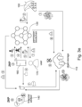
- the data sharing system 100 comprises a first data processing circuitry 110 configured to store user-specific data of a user 170 and at least one second data processing circuitry 120 which is configured to store access rights of an external entity 140 to access the user-specific data stored on the first data processing circuitry 110.
- the data sharing system 100 comprises a user interface 160 which is configured to authenticate the user 170 to the second data processing circuitry 120 for modifying the access rights.
- the first data processing circuitry 110 is designed as a cloud storage integrated in a network.
- the network for example comprises the interfaces 130' and 130'' to connect the cloud storage 110 with the external entities 140 and one or more nodes of a distributed ledger/blockchain (system) forming the second data processing circuitry 120.
- system distributed ledger/blockchain
- the data sharing system 100 may comprise multiple cloud storages 110.
- the second data processing circuitry 120 may also be referred to as a blockchain node.
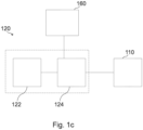
- the second data processing circuitry 120 which can also be referred to as access data processing circuitry, generally can comprise an access data storage 122.
- the access data storage is configured to store access rights of the external entity 140 to access user-specific data of the user 170 stored on the user data processing circuitry 110.
- the second data processing circuitry can comprise an interface 124 configured to communicate the access rights to the user data processing circuitry 110 storing the user-specific data for communicating portions of the user-specific data from the user data processing circuitry to the external entity in accordance with the access rights.
- the interface 124 further may enable the user 170 to modify the access rights in response to the user interface 160 authenticating the user 170.
- the access rights can be stored on the blockchain node 120 for a distributed and immutable repository of the user-specific data.
- the user 170 can connect to any of various nodes of the blockchain node 120, the user 170 can control sharing the user-specific data independently from a single of the various external entities 140 (e.g. companies or organizations).
- various external entities 140 e.g. companies or organizations
- the blockchain node 120 may include ownership rights which enable the user 170 to modify the access rights in case of a successful authentication of the user to the blockchain node 120.
- a first cryptographic (data ownership) accumulator may comprise at least one data ownership commitment and a second cryptographic (data access permission) accumulator may comprise multiple data access commitments.
- the access rights define which of the external entities may access which portion of the user-specific data.
- the access rights may allow the hospital 140, 150 to access a portion of the user-specific data comprising the medical findings of the preceding medical examinations but may also refrain the hospital from accessing another portion of the user-specific data regarding to financial matters of the user 170.
- the user interface for example, provides user-specific credentials to the blockchain node 120 for an authentication by reference to the user-specific credentials in response to a successful login of the user to an Application Programming Interface (API).
- API Application Programming Interface
- the external entities 140 and/or the data providing entities 150 provide the appropriate Application Programming Interface (API) to the user 170 or the user interface 160.
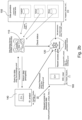
- FIG. 2a , 2b , 2f and 2h schematically illustrate further examples of the data sharing system 100.
- the external entities 140 and the data providing entities 150 are considered as separated for simplifying an explanation of the further examples of the data sharing system 100. However, the external entities 140 and the data providing entities 150 may also correspond to each other in general, as stated above.
- the data providing entities 150 can collect the user-specific data and transmit those to the cloud storage 110.
- the ownership rights can be indicative of a data ownership record 210 which enables the user 170 to modify the access rights, as stated in more detail later.
- the ownership record 210 can be set by one of the data providing entities 150 when they submit the user-specific data to the cloud storage 110.
- the user 170 can also set or modify ownership records.
- this can be encrypted with a public key 214 of the user interface and a first random value 216.
- the ownership record 210 can be shared with the user interface 160 to transmit the first random value 216 and the data ID 212.
- the external entities 140 can request to access the user-specific data.
- the external entities 140 can create an access request based on information of the user-specific data.
- the external entity 140 can ask the user 170 for a modification of the access rights which enables the external entity 140 to access requested user-specific data.
- the information can be stored and made publicly available on the cloud storage 110 by the user 170.
- the user 170 can set appropriate information access rights which enable the external entities 140 to create the access request by reference to the information of the user-specific data.
- the external entity 140 may transmit the access request to the user interface 160 via the API. Consequently, the user 170 may receive a notification from the user interface 160 with an option to whether reject the access request or to modify the access rights in accordance with the access request. In general, the user 170 can also modify the access rights such that the external entity 140 can (only) access a portion of the requested user-specific data.
- the external entity 140 can send a query to the cloud storage 110 to access the user-specific data.
- the cloud storage 110 may compare the query with the access rights stored on the blockchain node 120 to grant or reject an access of the external entity 140 to the user-specific data.
- the user interface 160 can authenticate the user 170 using a first zero knowledge proof 220 and the external entity 140 can prove its access rights using a second and/or a third zero knowledge proof 240.
- the user interface 160 is configured to generate the first zero knowledge proof 220 by applying a predefined logic 228 to a user-specific input.
- the data access commitment 230 can be generated by the user interface 160 using a second random value 226, the data ID 212 and a public key 224 of the external entity 140 as input.
- the user interface 160 can obtain the data ID 212 and the first random value 216 by decrypting the ownership record 210 obtained from the blockchain node 120.
- the user interface 160 can authenticate the user 170 through a comparison of the first cryptographic accumulator 222 with the data ownership commitment 218 stored on the blockchain node 120 using the first zero knowledge proof 220.
- the blockchain node 120 applies a verification program 221 to the first zero knowledge proof 220 for the comparison of the first cryptographic accumulator 222 with the data ownership commitment 218.
- the external entity 140 can invoke the second cryptographic accumulator 232 from the blockchain node 120 as entity-specific input of the second zero knowledge proof 240.
- the external entity 140 further creates the data access commitment 230 as further entity-specific input of the second zero knowledge proof 240 using the data ID 212, its public key 224 and the random value 226.
- the external entity 140 for example, creates the second zero knowledge proof 240 by applying another predefined logic to the entity-specific input.
- the cloud storage 110 can verify the access rights of the external entity 140 using the second cryptographic accumulator 232 stored on the blockchain node 120 for a comparison with the data access commitment 230 included in the second zero knowledge proof 240. For this, the cloud storage 110 can apply another verification program 221' to the second zero knowledge proof 240.
- the cloud storage 110 can provide the portion of the user-specific data with the appropriate data ID 212 to the external entity 140.
- Fig. 2f illustrates a third example of the data sharing system 100.
- the user-specific data may be stored on the cloud storage 110 in an encrypted form.
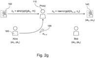
- the user interface 160 provides a re-encryption key 166 to the cloud storage 110 to generate re-encrypted user-specific data by "re-encrypting" the portion of the user-specific data to be provided to the external entity 140 in accordance with the access rights.
- the re-encryption key 166 may depend on the public key of the external entity 140 such that the re-encrypted user-specific data can be decrypted using the private key of the external entity 140.
- the re-encryption key 166 may also depend on the public key of the user interface 160 to enable the user 170 to access the user-specific data as well.
- the user-specific data is encrypted with a symmetric key which is also suitable for decrypting the user-specific data encrypted with the symmetric key.
- the cloud storage 110 may transfer the symmetric key from the user interface 160 to the external entity 140 for decrypting the user-specific data.
- Using the symmetric key may cause a faster encryption and/or decryption compared to an asymmetric encryption/decryption using pairs of public and private keys.
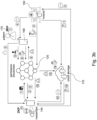
- Fig. 2h illustrates a fourth example of the data sharing system 100.
- the data sharing system 100 further comprises a third data processing circuitry storing a public blockchain 180.
- the user interface 160 for example, is registered with the public blockchain 180.
- the public blockchain 180 may assign the identity, a so-called Decentralized Identifier (DID), to the user interface 160 in response to a registration of the user interface 160 with the public blockchain 180.
- DID Decentralized Identifier
- the public blockchain 180 can determine an identity of the external entity 140 by reference to verifiable credentials provided by the external entity 140.
- the blockchain node 120 can provide the external entity 140 and/or the cloud storage with a portion of access rights by reference to the identity of the external entity 140.
- the user 170 is a graduate
- the external entity 140 is an interviewer
- the data providing entity 150 corresponds to a school of the graduate 170.
- the graduate 170 intends to share his user-specific data with the interviewer 140 in connection with a job application.
- the user-specific data for example, is a transcript.
- the interviewer 140 may send a data request to the user interface 160 of the graduate 170.
- the graduate 170 may accept the data request and return a download link to the interviewer 140.
- the user interface 160 can obtain the data ownership record from the blockchain node 120 to generate the first zero knowledge proof for an authentication.
- the interviewer 140 can generate the second zero knowledge proof based on the data access record and provides the second zero knowledge proof to the cloud storage 110 to verify his access rights to the cloud storage 110.
- the cloud storage 110 verifies the second zero knowledge proof by reference to the second cryptographic accumulator and provides the transcript to the interviewer 140.
- the user 170 corresponds to a patient
- the external entity 140 corresponds to a researcher
- the data providing entity 150 corresponds to a hospital.
- the researcher 140 can look up user-specific data stored on the cloud storage 110 with regard to an information associated with the user-specific data. For example, with respect to the information, the researcher 140 can recognize whether the user-specific data relate to a predefined medical issue or an economical issues.
- the cloud storage for example, stores user-specific data of multiple users/patients.
- one of the access requests may be transmitted to the user interface 160 via the hospital 150 to preserve a privacy and/or anonymity of the patient 170 towards the researcher 140.
- the patient 170 can allow the researcher 140 to access the user-specific data analogously, as described in connection with the first use case, to share the user-specific data with the researcher 140.
- the anonymity of the patient 170 and the researcher 140 may be preserved using the blockchain node 120 for transmitting the access request.
- the user 170 corresponds to a job seeker
- the external entities 140 correspond to various companies
- the data providing entity 150 corresponds to a school of the job seeker.
- the school 150 uploads user-specific data, such as a diploma, to the cloud storage 110. Further, the job seeker uploads further user-specific data, such as a curriculum vitae (CV), to the cloud storage.
- user-specific data such as a diploma
- CV curriculum vitae
- the job seeker 170 can proof its ownership of the diploma using the first zero knowledge proof. This may ensure that the job seeker may not use a fake diploma for a job application.
- the user interface 160 can transmit a download link to the various companies 140 such that the companies 140 can trigger a download of the CV and the diploma from the cloud storage. Furthermore, the job seeker 170 can modify the access rights in such a way that the various companies 140 can access the CV and the diploma.
- the data providing entity 150 corresponds to an insurance broker and the external entity 140 corresponds to a financial advisor.
- the insurance broker 150 may upload a portfolio as user-specific data to the cloud storage 110. Initially, the user 170 may allow the financial advisor 140 to access the portfolio.
- the user 170 can revoke the access rights of the financial advisor using the first zero knowledge proof for the authentication.
- the financial advisor 140 can create the second zero knowledge proof to access the portfolio. However, due to a revocation of the access rights by the user 170, the financial advisor 140 cannot access the portfolio.
- the user 170 can prevent a distribution of the user-specific/portfolio data to the financial advisor 140 although the user 170 previously allowed the financial advisor 140 to access the portfolio.
- Fig. 4 schematically illustrates a method 400 for sharing user-specific data.
- the method 400 comprises storing 410 the user-specific data of a user on a first data processing circuitry and storing 420 access rights of an external entity to access the user-specific data stored on the first data processing circuitry.
- the method 400 comprises communicating 430 the access rights from the second data processing circuitry to the first data processing circuitry and communicating 440 portions of the user-specific data from the first data processing circuitry to the external entity in accordance with the access rights.
- Examples may further be or relate to a computer program having a program code for performing one or more of the above methods, when the computer program is executed on a computer or processor. Steps, operations or processes of various above-described methods may be performed by programmed computers or processors. Examples may also cover program storage devices such as digital data storage media, which are machine, processor or computer readable and encode machine-executable, processor-executable or computer-executable programs of instructions. The instructions perform or cause performing some or all of the acts of the above-described methods.
- the program storage devices may comprise or be, for instance, digital memories, magnetic storage media such as magnetic disks and magnetic tapes, hard drives, or optically readable digital data storage media.
- FIG. 1 may also cover computers, processors or control units programmed to perform the acts of the above-described methods or (field) programmable logic arrays ((F)PLAs) or (field) programmable gate arrays ((F)PGAs), programmed to perform the acts of the above-described methods.
- a functional block denoted as "means for " performing a certain function may refer to a circuit that is configured to perform a certain function.
- a "means for s.th.” may be implemented as a "means configured to or suited for s.th.”, such as a device or a circuit configured to or suited for the respective task.
- Functions of various elements shown in the figures may be implemented in the form of dedicated hardware, such as “a signal provider”, “a signal processing unit”, “a processor”, “a controller”, etc. as well as hardware capable of executing software in association with appropriate software.
- a processor the functions may be provided by a single dedicated processor, by a single shared processor, or by a plurality of individual processors, some of which or all of which may be shared.
- processor or “controller” is by far not limited to hardware exclusively capable of executing software, but may include digital signal processor (DSP) hardware, network processor, application specific integrated circuit (ASIC), field programmable gate array (FPGA), read only memory (ROM) for storing software, random access memory (RAM), and non-volatile storage.
- DSP digital signal processor
- ASIC application specific integrated circuit
- FPGA field programmable gate array
- ROM read only memory
- RAM random access memory
- non-volatile storage Other hardware, conventional and/or custom, may also be included.
- a block diagram may, for instance, illustrate a high-level circuit diagram implementing the principles of the disclosure.
- a flow chart, a flow diagram, a state transition diagram, a pseudo code, and the like may represent various processes, operations or steps, which may, for instance, be substantially represented in computer readable medium and so executed by a computer or processor, whether or not such computer or processor is explicitly shown.
- Methods disclosed in the specification or in the claims may be implemented by a device having means for performing each of the respective acts of these methods.
Landscapes
- Engineering & Computer Science (AREA)
- Theoretical Computer Science (AREA)
- Computer Security & Cryptography (AREA)
- Health & Medical Sciences (AREA)
- Bioethics (AREA)
- General Health & Medical Sciences (AREA)
- General Engineering & Computer Science (AREA)
- Computer Hardware Design (AREA)
- Physics & Mathematics (AREA)
- Software Systems (AREA)
- General Physics & Mathematics (AREA)
- Medical Informatics (AREA)
- Databases & Information Systems (AREA)
- Computing Systems (AREA)
- Computer Networks & Wireless Communication (AREA)
- Signal Processing (AREA)
- Storage Device Security (AREA)
Claims (15)
- System zum gemeinsamen Nutzen von Daten, umfassend:eine erste Datenverarbeitungsschaltlogik (110), die konfiguriert ist, um benutzerspezifische Daten eines Benutzers (170) zu speichern;mindestens eine zweite Datenverarbeitungsschaltlogik (120), die konfiguriert ist, um Zugriffsrechte einer externen Entität zu speichern, um auf die benutzerspezifischen Daten zuzugreifen, die auf der ersten Datenverarbeitungsschaltlogik (110) gespeichert sind;eine Schnittstelle (130') zwischen der ersten Datenverarbeitungsschaltlogik (110) und der zweiten Datenverarbeitungsschaltlogik (120), die konfiguriert ist, um die Zugriffsrechte von der zweiten Datenverarbeitungsschaltlogik (120) an die erste Datenverarbeitungsschaltlogik (110) zu übermitteln;eine Benutzerschnittstelle (160), die konfiguriert ist, um den Benutzer gegenüber der zweiten Datenverarbeitungsschaltlogik (120) zum Modifizieren der Zugriffsrechte zu authentifizieren; undeine Schnittstelle (130") zwischen der ersten Datenverarbeitungsschaltlogik (110) und der externen Entität (140), die konfiguriert ist, um einen Anteil der benutzerspezifischen Daten an die externe Entität (140) gemäß den Zugriffsrechten zu übermitteln.
- System zum gemeinsamen Nutzen von Daten nach Anspruch 1, wobei die Benutzerschnittstelle (160) konfiguriert ist, um benutzerspezifische Berechtigungsdaten an die zweite Datenverarbeitungsschaltlogik (120) bereitzustellen, um den Benutzer (170) zu authentifizieren.
- System zum gemeinsamen Nutzen von Daten nach Anspruch 1 oder 2, wobei die zweite Datenverarbeitungsschaltlogik (120) ferner konfiguriert ist, um Eigentumsrechte des Benutzers zu speichern, um die Zugriffsrechte zu modifizieren.
- System zum gemeinsamen Nutzen von Daten nach Anspruch 3, wobei die zweite Datenverarbeitungsschaltlogik (120) ferner konfiguriert ist, um die Zugriffsrechte und die Eigentumsrechte in einer Blockchain zu speichern.
- System zum gemeinsamen Nutzen von Daten nach Anspruch 4, wobei die erste Datenverarbeitungsschaltlogik (110) ferner konfiguriert ist, um die Blockchain mit Zugriffsinformationen beim Übermitteln des Anteils der benutzerspezifischen Daten an die externe Entität (140) zu kombinieren.
- System zum gemeinsamen Nutzen von Daten nach einem der Ansprüche 3 bis 5, wobei die zweite Datenverarbeitungsschaltlogik (120) ferner konfiguriert ist, um einen ersten kryptografischen Akkumulator, der für die Eigentumsrechte definiert ist, und einen zweiten kryptografischen Akkumulator, der für die Zugriffsrechte definiert ist, zu speichern, wobei der erste kryptografische Akkumulator ein oder mehrere erste Elemente akkumuliert, die die bezeichnend für Eigentumsrechte sind, und der zweite kryptografische Akkumulator ein oder mehrere zweite Elemente akkumuliert, die bezeichnend für die Zugriffsrechte sind.
- System zum gemeinsamen Nutzen von Daten nach Anspruch 6, wobei die Benutzerschnittstelle (160) ferner konfiguriert ist, um der zweiten Datenverarbeitungsschaltlogik (120) einen ersten Nullwissen-Nachweis bereitzustellen, wobei der erste kryptografische Akkumulator konfiguriert ist, um den Benutzer durch Verifizieren, dass eine benutzerspezifische Eingabe des ersten Nullwissen-Nachweises mindestens einem der ersten Elemente entspricht, die durch den ersten kryptografischen Akkumulator akkumuliert sind, zu authentifizieren.
- System zum gemeinsamen Nutzen von Daten nach Anspruch 6, wobei die erste Datenverarbeitungsschaltlogik (110) ferner konfiguriert ist, um von der externen Entität (140) einen zweiten Nullwissen-Nachweis zu erhalten, wobei der zweite kryptografische Akkumulator konfiguriert ist, um ein Eigentum der Zugriffsrechte durch Verifizieren, dass eine einheitenspezifische Eingabe des zweiten Nullwissen-Nachweises mindestens einem der zweiten Elemente entspricht, die durch den zweiten kryptografischen Akkumulator für eine Verifikation des zweiten Nullwissen-Nachweises akkumuliert sind, nachzuweisen, und wobei die Schnittstelle (130') zwischen der ersten und der zweiten Datenverarbeitungsschaltlogik (110, 120) ferner konfiguriert ist, um die Zugriffsrechte von der zweiten Datenverarbeitungsschaltlogik (120) in Abhängigkeit von der Verifikation des zweiten Nullwissen-Nachweises zu übermitteln.
- System zum gemeinsamen Nutzen von Daten nach einem der Ansprüche 1 bis 8,wobei die benutzerspezifischen Daten mit einem symmetrischen Schlüssel verschlüsselt werden, der zum Entschlüsseln der benutzerspezifischen Daten, die mit dem symmetrischen Schlüssel verschlüsselt sind, geeignet ist; undwobei die erste Datenverarbeitungsschaltlogik (110) ferner konfiguriert ist zum: Erhalten des symmetrischen Schlüssels von der Benutzerschnittstelle (160); undBereitstellen des symmetrischen Schlüssels für die externe Entität (140) zum Entschlüsseln der benutzerspezifischen Daten.
- System zum gemeinsamen Nutzen von Daten nach einem der Ansprüche 1 bis 9, wobei die Benutzerschnittstelle (160) konfiguriert ist zumGenerieren eines Neuverschlüsselungsschlüssels in Abhängigkeit von einem öffentlichen Schlüssel der externen Entität (140);Bereitstellen des Neuverschlüsselungsschlüssels an die erste Datenverarbeitungsschaltlogik (110),wobei die erste Datenverarbeitungsschaltlogik (110) ferner konfiguriert ist zumGenerieren von neuverschlüsselten benutzerspezifischen Daten durch Neuverschlüsseln des Anteils der benutzerspezifischen Daten, wobei die neuverschlüsselten benutzerspezifischen Daten unter Verwendung eines privaten Schlüssels, der sich auf den öffentlichen Schlüssel bezieht, entschlüsselbar sind,Bereitstellen der neuverschlüsselten benutzerspezifischen Daten an die externe Entität (140).
- System zum gemeinsamen Nutzen von Daten nach einem der Ansprüche 1 bis 10, wobei die Benutzerschnittstelle (160) ferner konfiguriert ist zum:Erhalten einer Zugriffsanforderung für die externe Entität, um auf einen angeforderten Anteil der benutzerspezifischen Daten zuzugreifen; undModifizieren der Zugriffsrechte gemäß der Zugriffsanforderung.
- Verfahren (400) zum gemeinsamen Nutzen von benutzerspezifischen Daten, umfassend:Speichern (410) von benutzerspezifischen Daten eines Benutzers auf einer ersten Datenverarbeitungsschaltlogik (110);Speichern (420), auf einer zweiten Datenverarbeitungsschaltlogik (120), von Zugriffsrechten einer externen Entität, um auf die benutzerspezifischen Daten, die auf der ersten Datenverarbeitungsschaltlogik gespeichert sind, zuzugreifen;Übermitteln (430) der Zugriffsrechte von der zweiten Datenverarbeitungsschaltlogik (120) an die erste Datenverarbeitungsschaltlogik (110); undÜbermitteln (440) von Anteilen der benutzerspezifischen Daten von der ersten Datenverarbeitungsschaltlogik (110) an die externe Entität (140) gemäß den Zugriffsrechten.
- Computerprogramm, umfassend Anweisung, die, wenn sie durch mindestens einen Prozessor ausgeführt werden, den Prozessor dazu veranlassen, das Verfahren nach Anspruch 12 durchzuführen.
- Erste Datenverarbeitungsschaltlogik (110), umfassend:einen Benutzerdatenspeicher (112), der konfiguriert ist, um benutzerspezifische Daten eines Benutzers zu speichern; undeine Schnittstelle (114), die konfiguriert ist zumErhalten von Zugriffsrechten einer externen Entität (140), um auf die benutzerspezifischen Daten von einer zweiten Datenverarbeitungsschaltlogik (120) zuzugreifen; undÜbermitteln eines Anteils der benutzerspezifischen Daten an die externe Entität (140) gemäß den Zugriffsrechten.
- Zweite Datenverarbeitungsschaltlogik (120), umfassend:einen Zugriffsdatenspeicher (122), der konfiguriert ist zum
Speichern von Zugriffsrechten einer externen Entität (140), um auf benutzerspezifische Daten eines Benutzers zuzugreifen, die in einer ersten Datenverarbeitungsschaltlogik (110) gespeichert sind; undeine Schnittstelle (124), die konfiguriert ist zumÜbermitteln der Zugriffsrechte an die erste Datenverarbeitungsschaltlogik (110), in der die benutzerspezifischen Daten gespeichert sind, zum Übermitteln von Anteilen der benutzerspezifischen Daten von der ersten Datenverarbeitungsschaltlogik (110) an die externe Entität (140) gemäß den Zugriffsrechten; undAktivieren eines Benutzers (170), um die Zugriffsrechte als Reaktion auf eine Benutzerschnittstelle (160) zu modifizieren, die den Benutzer (170) authentifiziert.
Applications Claiming Priority (3)
| Application Number | Priority Date | Filing Date | Title |
|---|---|---|---|
| EP19213237 | 2019-12-03 | ||
| EP19216210 | 2019-12-13 | ||
| PCT/EP2020/083104 WO2021110462A1 (en) | 2019-12-03 | 2020-11-23 | Method, computer program and data sharing system for sharing user-specific data of a user |
Publications (2)
| Publication Number | Publication Date |
|---|---|
| EP4070519A1 EP4070519A1 (de) | 2022-10-12 |
| EP4070519B1 true EP4070519B1 (de) | 2025-04-09 |
Family
ID=73452227
Family Applications (1)
| Application Number | Title | Priority Date | Filing Date |
|---|---|---|---|
| EP20807817.0A Active EP4070519B1 (de) | 2019-12-03 | 2020-11-23 | Verfahren, computerprogramm und system zur gemeinsamen nutzung von daten zur gemeinsamen nutzung benutzerspezifischer daten eines benutzers |
Country Status (4)
| Country | Link |
|---|---|
| US (1) | US12493714B2 (de) |
| EP (1) | EP4070519B1 (de) |
| CN (1) | CN114762291A (de) |
| WO (1) | WO2021110462A1 (de) |
Families Citing this family (4)
| Publication number | Priority date | Publication date | Assignee | Title |
|---|---|---|---|---|
| CN115438353A (zh) * | 2021-06-04 | 2022-12-06 | 华为技术有限公司 | 一种用户数据管理方法以及相关设备 |
| CN116090016B (zh) * | 2023-04-10 | 2023-07-11 | 江苏省国信数字科技有限公司 | 区块链数据存储隐私保护方法、装置、设备及存储介质 |
| CN117993017B (zh) * | 2024-03-29 | 2024-06-07 | 苏州元脑智能科技有限公司 | 数据共享系统、方法、装置、计算机设备及存储介质 |
| US12126623B1 (en) * | 2024-04-30 | 2024-10-22 | Citibank, N.A. | Aggregated authorization token |
Family Cites Families (9)
| Publication number | Priority date | Publication date | Assignee | Title |
|---|---|---|---|---|
| WO2011003953A2 (de) * | 2009-07-07 | 2011-01-13 | Fraunhofer-Gesellschaft Zur Foerderung Der Angewandten Forschung E.V. | Pseudonymisierte authentifizierung |
| JP6452156B2 (ja) * | 2015-09-03 | 2019-01-16 | 日本電信電話株式会社 | 許諾情報管理システム、利用者端末、権利者端末、許諾情報管理方法、および、許諾情報管理プログラム |
| KR102470727B1 (ko) * | 2016-12-30 | 2022-11-25 | 비씨 디벨롭먼트 랩스 게엠베하 | 블록체인 가능한 서비스 제공자 시스템 |
| FR3079323B1 (fr) * | 2018-03-26 | 2020-04-17 | Commissariat A L'energie Atomique Et Aux Energies Alternatives | Methode et systeme d'acces a des donnees anonymisees |
| US10929352B2 (en) | 2018-05-29 | 2021-02-23 | Oracle International Corporation | Securing access to confidential data using a blockchain ledger |
| CN109326337B (zh) * | 2018-09-06 | 2021-09-03 | 西安电子科技大学 | 基于区块链的电子医疗记录存储和共享的模型及方法 |
| CN109450910B (zh) | 2018-11-26 | 2021-03-30 | 远光软件股份有限公司 | 基于区块链的数据共享方法、数据共享网络及电子设备 |
| CN110061988B (zh) | 2019-04-19 | 2022-06-10 | 深圳市网心科技有限公司 | 嵌入式设备的鉴权方法、嵌入式设备、业务服务器及存储介质 |
| US11469886B2 (en) * | 2019-05-22 | 2022-10-11 | Salesforce.Com, Inc. | System or method to implement record level access on metadata driven blockchain using shared secrets and consensus on read |
-
2020
- 2020-11-23 EP EP20807817.0A patent/EP4070519B1/de active Active
- 2020-11-23 WO PCT/EP2020/083104 patent/WO2021110462A1/en not_active Ceased
- 2020-11-23 US US17/779,569 patent/US12493714B2/en active Active
- 2020-11-23 CN CN202080082175.5A patent/CN114762291A/zh active Pending
Also Published As
| Publication number | Publication date |
|---|---|
| CN114762291A (zh) | 2022-07-15 |
| EP4070519A1 (de) | 2022-10-12 |
| US12493714B2 (en) | 2025-12-09 |
| WO2021110462A1 (en) | 2021-06-10 |
| US20230010786A1 (en) | 2023-01-12 |
Similar Documents
| Publication | Publication Date | Title |
|---|---|---|
| Thwin et al. | Blockchain‐based access control model to preserve privacy for personal health record systems | |
| Fabian et al. | Collaborative and secure sharing of healthcare data in multi-clouds | |
| EP2513804B1 (de) | Zuverlässige erweiterbare markierungssprache für zuverlässige berechnungs- und datendienste | |
| US10275603B2 (en) | Containerless data for trustworthy computing and data services | |
| EP2396922B1 (de) | Sicheres rahmenwerk für cloud-computing und entsprechende dienste | |
| EP2396921B1 (de) | Sicheres rahmenwerk für cloud-computing und entsprechende dienste | |
| US12493714B2 (en) | Method, computer program and data sharing system for sharing user-specific data of a user | |
| CN102656589A (zh) | 通过包装器合成的用于数据的可验证的信任 | |
| Ghorbel et al. | Accountable privacy preserving attribute-based access control for cloud services enforced using blockchain | |
| CN112926082B (zh) | 一种基于区块链的信息处理方法及装置 | |
| Satybaldy et al. | Decentralized identity management for E-health applications: State-of-the-art and guidance for future work | |
| WO2014064323A1 (en) | Method and apparatus for managing access rights | |
| Karegar et al. | Opportunities and challenges of CREDENTIAL: towards a metadata-privacy respecting identity provider | |
| Thakkar et al. | A privacy-preserving framework using hyperledger fabric for EHR sharing applications | |
| US12309274B2 (en) | Cryptography-as-a-service | |
| Paik et al. | Decentralized Identity Management and Blockchains: Design Patterns and Architectures | |
| Onamade et al. | The use of self-sovereign identity in blockchain systems | |
| Abouakil et al. | Data models for the pseudonymization of DICOM data | |
| Vanjipriya et al. | Blockchain-Based Access Control with Decentralized Architecture for Data Storage and Transfer | |
| US12395329B1 (en) | Record-level encryption scheme for data ownership platform | |
| Zhang et al. | Secure deduplication | |
| Vrielynck | A decentralized access control and resource delegation framework | |
| Alniamy | Blockchain-Based Secure Collaboration for Sharing and Accessing Research Data | |
| Thwin et al. | Research Article Blockchain-Based Access Control Model to Preserve Privacy for Personal Health Record Systems | |
| Altameem | Enhancing Cloud Based Information System Security Using the Role and Identity Based Access Control with Fully Homomorphic Encryption |
Legal Events
| Date | Code | Title | Description |
|---|---|---|---|
| STAA | Information on the status of an ep patent application or granted ep patent |
Free format text: STATUS: UNKNOWN |
|
| STAA | Information on the status of an ep patent application or granted ep patent |
Free format text: STATUS: THE INTERNATIONAL PUBLICATION HAS BEEN MADE |
|
| PUAI | Public reference made under article 153(3) epc to a published international application that has entered the european phase |
Free format text: ORIGINAL CODE: 0009012 |
|
| STAA | Information on the status of an ep patent application or granted ep patent |
Free format text: STATUS: REQUEST FOR EXAMINATION WAS MADE |
|
| 17P | Request for examination filed |
Effective date: 20220704 |
|
| AK | Designated contracting states |
Kind code of ref document: A1 Designated state(s): AL AT BE BG CH CY CZ DE DK EE ES FI FR GB GR HR HU IE IS IT LI LT LU LV MC MK MT NL NO PL PT RO RS SE SI SK SM TR |
|
| DAV | Request for validation of the european patent (deleted) | ||
| DAX | Request for extension of the european patent (deleted) | ||
| STAA | Information on the status of an ep patent application or granted ep patent |
Free format text: STATUS: EXAMINATION IS IN PROGRESS |
|
| 17Q | First examination report despatched |
Effective date: 20240227 |
|
| REG | Reference to a national code |
Ref country code: DE Ref legal event code: R079 Free format text: PREVIOUS MAIN CLASS: H04L0029060000 Ipc: H04L0009400000 Ref country code: DE Ref legal event code: R079 Ref document number: 602020049200 Country of ref document: DE Free format text: PREVIOUS MAIN CLASS: H04L0029060000 Ipc: H04L0009400000 |
|
| GRAP | Despatch of communication of intention to grant a patent |
Free format text: ORIGINAL CODE: EPIDOSNIGR1 |
|
| STAA | Information on the status of an ep patent application or granted ep patent |
Free format text: STATUS: GRANT OF PATENT IS INTENDED |
|
| RIC1 | Information provided on ipc code assigned before grant |
Ipc: G06F 21/62 20130101ALI20241011BHEP Ipc: H04L 9/40 20220101AFI20241011BHEP |
|
| INTG | Intention to grant announced |
Effective date: 20241119 |
|
| GRAS | Grant fee paid |
Free format text: ORIGINAL CODE: EPIDOSNIGR3 |
|
| GRAA | (expected) grant |
Free format text: ORIGINAL CODE: 0009210 |
|
| STAA | Information on the status of an ep patent application or granted ep patent |
Free format text: STATUS: THE PATENT HAS BEEN GRANTED |
|
| P01 | Opt-out of the competence of the unified patent court (upc) registered |
Free format text: CASE NUMBER: APP_7185/2025 Effective date: 20250212 |
|
| AK | Designated contracting states |
Kind code of ref document: B1 Designated state(s): AL AT BE BG CH CY CZ DE DK EE ES FI FR GB GR HR HU IE IS IT LI LT LU LV MC MK MT NL NO PL PT RO RS SE SI SK SM TR |
|
| REG | Reference to a national code |
Ref country code: GB Ref legal event code: FG4D |
|
| REG | Reference to a national code |
Ref country code: CH Ref legal event code: EP |
|
| REG | Reference to a national code |
Ref country code: DE Ref legal event code: R096 Ref document number: 602020049200 Country of ref document: DE |
|
| REG | Reference to a national code |
Ref country code: IE Ref legal event code: FG4D |
|
| REG | Reference to a national code |
Ref country code: NL Ref legal event code: MP Effective date: 20250409 |
|
| PG25 | Lapsed in a contracting state [announced via postgrant information from national office to epo] |
Ref country code: NL Free format text: LAPSE BECAUSE OF FAILURE TO SUBMIT A TRANSLATION OF THE DESCRIPTION OR TO PAY THE FEE WITHIN THE PRESCRIBED TIME-LIMIT Effective date: 20250409 |
|
| REG | Reference to a national code |
Ref country code: AT Ref legal event code: MK05 Ref document number: 1784572 Country of ref document: AT Kind code of ref document: T Effective date: 20250409 |
|
| PG25 | Lapsed in a contracting state [announced via postgrant information from national office to epo] |
Ref country code: FI Free format text: LAPSE BECAUSE OF FAILURE TO SUBMIT A TRANSLATION OF THE DESCRIPTION OR TO PAY THE FEE WITHIN THE PRESCRIBED TIME-LIMIT Effective date: 20250409 Ref country code: ES Free format text: LAPSE BECAUSE OF FAILURE TO SUBMIT A TRANSLATION OF THE DESCRIPTION OR TO PAY THE FEE WITHIN THE PRESCRIBED TIME-LIMIT Effective date: 20250409 Ref country code: PT Free format text: LAPSE BECAUSE OF FAILURE TO SUBMIT A TRANSLATION OF THE DESCRIPTION OR TO PAY THE FEE WITHIN THE PRESCRIBED TIME-LIMIT Effective date: 20250811 |
|
| REG | Reference to a national code |
Ref country code: LT Ref legal event code: MG9D |
|
| PG25 | Lapsed in a contracting state [announced via postgrant information from national office to epo] |
Ref country code: GR Free format text: LAPSE BECAUSE OF FAILURE TO SUBMIT A TRANSLATION OF THE DESCRIPTION OR TO PAY THE FEE WITHIN THE PRESCRIBED TIME-LIMIT Effective date: 20250710 Ref country code: NO Free format text: LAPSE BECAUSE OF FAILURE TO SUBMIT A TRANSLATION OF THE DESCRIPTION OR TO PAY THE FEE WITHIN THE PRESCRIBED TIME-LIMIT Effective date: 20250709 |
|
| PG25 | Lapsed in a contracting state [announced via postgrant information from national office to epo] |
Ref country code: PL Free format text: LAPSE BECAUSE OF FAILURE TO SUBMIT A TRANSLATION OF THE DESCRIPTION OR TO PAY THE FEE WITHIN THE PRESCRIBED TIME-LIMIT Effective date: 20250409 |
|
| PG25 | Lapsed in a contracting state [announced via postgrant information from national office to epo] |
Ref country code: BG Free format text: LAPSE BECAUSE OF FAILURE TO SUBMIT A TRANSLATION OF THE DESCRIPTION OR TO PAY THE FEE WITHIN THE PRESCRIBED TIME-LIMIT Effective date: 20250409 |
|
| PG25 | Lapsed in a contracting state [announced via postgrant information from national office to epo] |
Ref country code: HR Free format text: LAPSE BECAUSE OF FAILURE TO SUBMIT A TRANSLATION OF THE DESCRIPTION OR TO PAY THE FEE WITHIN THE PRESCRIBED TIME-LIMIT Effective date: 20250409 |
|
| PG25 | Lapsed in a contracting state [announced via postgrant information from national office to epo] |
Ref country code: AT Free format text: LAPSE BECAUSE OF FAILURE TO SUBMIT A TRANSLATION OF THE DESCRIPTION OR TO PAY THE FEE WITHIN THE PRESCRIBED TIME-LIMIT Effective date: 20250409 |
|
| PG25 | Lapsed in a contracting state [announced via postgrant information from national office to epo] |
Ref country code: RS Free format text: LAPSE BECAUSE OF FAILURE TO SUBMIT A TRANSLATION OF THE DESCRIPTION OR TO PAY THE FEE WITHIN THE PRESCRIBED TIME-LIMIT Effective date: 20250709 |
|
| PG25 | Lapsed in a contracting state [announced via postgrant information from national office to epo] |
Ref country code: IS Free format text: LAPSE BECAUSE OF FAILURE TO SUBMIT A TRANSLATION OF THE DESCRIPTION OR TO PAY THE FEE WITHIN THE PRESCRIBED TIME-LIMIT Effective date: 20250809 |
|
| PG25 | Lapsed in a contracting state [announced via postgrant information from national office to epo] |
Ref country code: LV Free format text: LAPSE BECAUSE OF FAILURE TO SUBMIT A TRANSLATION OF THE DESCRIPTION OR TO PAY THE FEE WITHIN THE PRESCRIBED TIME-LIMIT Effective date: 20250409 |
|
| PGFP | Annual fee paid to national office [announced via postgrant information from national office to epo] |
Ref country code: DE Payment date: 20251022 Year of fee payment: 6 |
|
| PGFP | Annual fee paid to national office [announced via postgrant information from national office to epo] |
Ref country code: GB Payment date: 20251022 Year of fee payment: 6 |
|
| REG | Reference to a national code |
Ref country code: DE Ref legal event code: R097 Ref document number: 602020049200 Country of ref document: DE |
|
| PG25 | Lapsed in a contracting state [announced via postgrant information from national office to epo] |
Ref country code: SM Free format text: LAPSE BECAUSE OF FAILURE TO SUBMIT A TRANSLATION OF THE DESCRIPTION OR TO PAY THE FEE WITHIN THE PRESCRIBED TIME-LIMIT Effective date: 20250409 Ref country code: DK Free format text: LAPSE BECAUSE OF FAILURE TO SUBMIT A TRANSLATION OF THE DESCRIPTION OR TO PAY THE FEE WITHIN THE PRESCRIBED TIME-LIMIT Effective date: 20250409 |
|
| PG25 | Lapsed in a contracting state [announced via postgrant information from national office to epo] |
Ref country code: CZ Free format text: LAPSE BECAUSE OF FAILURE TO SUBMIT A TRANSLATION OF THE DESCRIPTION OR TO PAY THE FEE WITHIN THE PRESCRIBED TIME-LIMIT Effective date: 20250409 |
|
| PG25 | Lapsed in a contracting state [announced via postgrant information from national office to epo] |
Ref country code: EE Free format text: LAPSE BECAUSE OF FAILURE TO SUBMIT A TRANSLATION OF THE DESCRIPTION OR TO PAY THE FEE WITHIN THE PRESCRIBED TIME-LIMIT Effective date: 20250409 |
|
| PG25 | Lapsed in a contracting state [announced via postgrant information from national office to epo] |
Ref country code: SK Free format text: LAPSE BECAUSE OF FAILURE TO SUBMIT A TRANSLATION OF THE DESCRIPTION OR TO PAY THE FEE WITHIN THE PRESCRIBED TIME-LIMIT Effective date: 20250409 |
|
| PG25 | Lapsed in a contracting state [announced via postgrant information from national office to epo] |
Ref country code: IT Free format text: LAPSE BECAUSE OF FAILURE TO SUBMIT A TRANSLATION OF THE DESCRIPTION OR TO PAY THE FEE WITHIN THE PRESCRIBED TIME-LIMIT Effective date: 20250409 |
|
| PG25 | Lapsed in a contracting state [announced via postgrant information from national office to epo] |
Ref country code: RO Free format text: LAPSE BECAUSE OF FAILURE TO SUBMIT A TRANSLATION OF THE DESCRIPTION OR TO PAY THE FEE WITHIN THE PRESCRIBED TIME-LIMIT Effective date: 20250409 |
|
| PLBE | No opposition filed within time limit |
Free format text: ORIGINAL CODE: 0009261 |
|
| STAA | Information on the status of an ep patent application or granted ep patent |
Free format text: STATUS: NO OPPOSITION FILED WITHIN TIME LIMIT |
|
| REG | Reference to a national code |
Ref country code: CH Ref legal event code: L10 Free format text: ST27 STATUS EVENT CODE: U-0-0-L10-L00 (AS PROVIDED BY THE NATIONAL OFFICE) Effective date: 20260218 |
|
| 26N | No opposition filed |
Effective date: 20260112 |