EP4070290B1 - Erzeugung von unterirdischen darstellungen unter verwendung eines schichtraums - Google Patents
Erzeugung von unterirdischen darstellungen unter verwendung eines schichtraums Download PDFInfo
- Publication number
- EP4070290B1 EP4070290B1 EP20895849.6A EP20895849A EP4070290B1 EP 4070290 B1 EP4070290 B1 EP 4070290B1 EP 20895849 A EP20895849 A EP 20895849A EP 4070290 B1 EP4070290 B1 EP 4070290B1
- Authority
- EP
- European Patent Office
- Prior art keywords
- subsurface
- representations
- tiles
- conditioning
- tile
- Prior art date
- Legal status (The legal status is an assumption and is not a legal conclusion. Google has not performed a legal analysis and makes no representation as to the accuracy of the status listed.)
- Active
Links
Images


Classifications
-
- G—PHYSICS
- G06—COMPUTING OR CALCULATING; COUNTING
- G06T—IMAGE DATA PROCESSING OR GENERATION, IN GENERAL
- G06T17/00—Three-dimensional [3D] modelling for computer graphics
-
- G—PHYSICS
- G06—COMPUTING OR CALCULATING; COUNTING
- G06T—IMAGE DATA PROCESSING OR GENERATION, IN GENERAL
- G06T17/00—Three-dimensional [3D] modelling for computer graphics
- G06T17/20—Finite element generation, e.g. wire-frame surface description, tesselation
-
- G—PHYSICS
- G01—MEASURING; TESTING
- G01V—GEOPHYSICS; GRAVITATIONAL MEASUREMENTS; DETECTING MASSES OR OBJECTS; TAGS
- G01V20/00—Geomodelling in general
-
- G—PHYSICS
- G01—MEASURING; TESTING
- G01V—GEOPHYSICS; GRAVITATIONAL MEASUREMENTS; DETECTING MASSES OR OBJECTS; TAGS
- G01V2210/00—Details of seismic processing or analysis
- G01V2210/60—Analysis
- G01V2210/66—Subsurface modeling
- G01V2210/661—Model from sedimentation process modeling, e.g. from first principles
-
- G—PHYSICS
- G06—COMPUTING OR CALCULATING; COUNTING
- G06F—ELECTRIC DIGITAL DATA PROCESSING
- G06F30/00—Computer-aided design [CAD]
- G06F30/20—Design optimisation, verification or simulation
- G06F30/23—Design optimisation, verification or simulation using finite element methods [FEM] or finite difference methods [FDM]
Definitions
- the present disclosure relates generally to the field of generating representations of subsurface using layer space.
- Subsurface simulations face competing challenges of honoring conditioning subsurface characteristics versus maintaining subsurface realism. For example, simulations produced using Cartesian grids precludes modeling of small-scale continuous layers. Honoring conditioning subsurface characteristics may be difficult for process-based approaches. Reference may be made to HARRIS SIMON ET AL: "SPE-193202-MS Complex Geological Modeling and Quality Assurance Using Unstructured Grids", ABU DHABI INTERNATIONAL PETROLEUM EXHIBITION & CONFERENCE, 12 November 2018 , which relates to a structural modeling and gridding workflow. A volume-based 3D structural model based on fault and horizon surfaces is constructed from input data.
- a definition of a flattened ('depositional') space that deforms the structural model mesh under mechanical constraints is created.
- a 3D 'unstructured' grid is created in the depositional space, based on 'cutting' a property-populated, regular cuboidal grid by the geological discontinuities.
- the representation information defines one or more sets of computational stratigraphy model representations.
- the set(s) of computational stratigraphy model representations define subsurface configurations in a physical space such that the subsurface configurations are defined as a function of depth.
- the conditioning information defines one or more conditioning characteristics in the physical space such that the conditioning characteristic(s) are defined as the function of depth.
- the set(s) of computational stratigraphy model representations are converted from the physical space to a layer space such that the subsurface configurations are defined as a function of layers (and lateral spatial location).
- the conditioning information are converted from the physical space to the layer space such that the conditioning characteristic(s) are defined as the function of layers (and lateral spatial location).
- Modeling is performed within the layer space based on the set(s) of computational stratigraphy model representations within the layer space and the conditioning characteristic(s) within the layer space to generate multiple subsurface representations within the layer space.
- the multiple subsurface representations include regions of the subsurface configurations defined by the set of computational stratigraphy model representations based on the conditioning characteristic(s).
- the multiple subsurface representations are converted from the layer space to the physical space.
- a system that generates subsurface representations may include one or more electronic storage, one or more processors and/or other components.
- the electronic storage may store representation information, information relating to subsurface representations, information relating to subsurface configurations, conditioning information, information relating to conditioning characteristics, information relating to physical space, information relating to layer space, information relating to conversion between physical space and layer space, information relating to modeling, and/or other information.
- the processor(s) may be configured by machine-readable instructions. Executing the machine-readable instructions may cause the processor(s) to facilitate generating subsurface representations.
- the machine-readable instructions may include one or more computer program components.
- the computer program components may include one or more of a representation information component, a conditioning information component, a layer space component, a modeling component, a physical space component, and/or other computer program components.
- the representation information component is configured to obtain representation information.
- the representation information defines one or more sets of computational stratigraphy model representations.
- a set of computational stratigraphy model representations defines subsurface configurations in a physical space such that the subsurface configurations are defined as a function of depth.
- the conditioning information component is configured to obtain conditioning information.
- the conditioning information e.g., geological data, petrophysical data, geophysical data, seismic data
- the conditioning characteristic(s) are determined based on one or more well logs obtained from borehole logging and/or interpreted seismic information.
- the layer space component is configured to convert the conditioning information from the physical space to a layer space such that the conditioning characteristic(s) are defined as a function of layers.
- the layer space component is configured to convert the set(s) of computational stratigraphy model representations from the physical space to the layer space such that the subsurface configurations are defined as the function of layers.
- the set(s) of computational stratigraphy model representations in the layer space may define the subsurface configurations using cells within individual computational stratigraphy model grid layers.
- the cells may be characterized by a cell thickness, one or more properties of interest, and/or other information.
- the propert(ies) of interest may include a grain size, a grain type, a grain lithology, a porosity, a permeability, and/or other propert(ies).
- the modeling component is configured to perform modeling within the layer space based on the set(s) of computational stratigraphy model representations within the layer space and the conditioning characteristic(s) within the layer space to generate multiple subsurface representations within the layer space.
- the subsurface representations include regions of the subsurface configurations defined by the set of computational stratigraphy model representations based on the conditioning characteristics .
- the modeling may be performed using a multi-point statistics technique and/or other techniques.
- the set(s) of computational stratigraphy model representations may be used as a set of training images in the multi-point statistics technique.
- performance of the modeling may include, for an individual subsurface representation, generation of a simulation domain to define one or more properties of interest and a cell thickness for individual cells.
- the simulation domain may be populated with the conditioning characteristic(s).
- the simulation domain may be partitioned into tiles, with individual tiles having a core region and a peripheral region. At least some of the peripherical region of an individual tile may overlap with the core region of a neighboring tile.
- the tiles may include a set of partially populated tiles and a set of unpopulated tiles.
- the set of partially populated tiles may include one or more partially populated tiles populated with at least one of the conditioning characteristic(s).
- the set of unpopulated tiles may include one or more unpopulated tiles not populated with any of the conditioning characteristic(s).
- individual populated tiles may be filled based on partially populated tile matching regions of the subsurface configurations and/or other information.
- the partially populated tile matching regions may be determined based on matching with the conditioning characteristic(s) within the individual partially populated tiles and/or other information.
- Individual unpopulated tiles may be filled based on unpopulated tile matching regions of the subsurface configurations and/or other information.
- the unpopulated tile matching regions may be determined based on continuity with one or more neighboring tiles and/or other information.
- the individual partially populated tiles may be filled prior to filling of the individual unpopulated tiles.
- the partially populated tile matching regions may be determined further based on a continuity score between a search template in the layer space and a computational stratigraphy model representation in the layer space.
- An order in which the individual unpopulated tiles are filled may be determined based on a raster path and/or other information.
- the raster path may prioritize in the order the unpopulated tiles adjacent to one or more of populated tiles over the unpopulated tiles not adjacent to any of the populated tiles.
- the physical space component is configured to convert the multiple subsurface representations from the layer space to the physical space.
- the subsurface representation(s) may model small-scale continuous layers and maintain physically plausible continuities of the set(s) of computational stratigraphy model representations, while jointly honoring the conditioning characteristic(s).
- the present disclosure relates to generating subsurface representations.
- Data in physical space are converted to layer space before performing modeling to generate one or more subsurface representations.
- Computational stratigraphy model representations that define subsurface configurations as a function of depth (and lateral spatial location) in the physical space are converted to the layer space so that the subsurface configurations are defined as a function of layers (and lateral spatial location).
- Conditioning information that defines conditioning characteristics as the function of depth (and lateral spatial location) in the physical space are converted to the layer space so that the conditioning characteristics are defined as the function of layers (and lateral spatial location).
- Modeling is performed in the layer space to generate subsurface representations within layer space, and the subsurface representations are converted into the physical space.
- Such subsurface representations may model small-scale continuous layers and maintain physically plausible continuities of the computational stratigraphy model representations, while jointly honoring the conditioning characteristics.
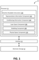
- the methods of the present disclosure are implemented by and/or in a computing system, such as a system 10 shown in FIG. 1 .
- the system 10 may include one or more of a processor 11, an interface 12 (e.g., bus, wireless interface), an electronic storage 13, and/or other components.
- Representation information, conditioning information, and/or other information may be obtained by the processor 11.
- the representation information defines one or more sets of computational stratigraphy model representations.
- the set(s) of computational stratigraphy model representations define subsurface configurations in the physical space such that the subsurface configurations are defined as a function of depth (and lateral spatial location), wherein the set of computational stratigraphy model representations are generated layer-by-layer using a forward stratigraphic model that simulates one or more sedimentary processes.
- the conditioning information defines one or more conditioning characteristics in the physical space such that the conditioning characteristic(s) are defined as the function of depth (and lateral spatial location), wherein the one or more conditioning characteristics are determined based on one or more well logs obtained from borehole logging and/or interpreted seismic information.
- the set(s) of computational stratigraphy model representations are converted by the processor 11 from the physical space to the layer space such that the subsurface configurations are defined as a function of layers (and lateral spatial (location), wherein the set of computational stratigraphy model representations are converted from the physical space to the layer space based on the layer-by-layer generation of the set of computational stratigraphy model representations by the forward stratigraphic model.
- the conditioning information is converted by the processor 11 from the physical space to the layer space such that the conditioning characteristic(s) are defined as the function of layers (and lateral spatial location).
- Modeling is performed by the processor 11 within the layer space based on the set(s) of computational stratigraphy model representations within the layer space, the conditioning characteristic(s) within the layer space, to generate multiple subsurface representations within the layer space.
- the subsurface representations include regions of the subsurface configurations defined by the set of computational stratigraphy model representations based on the conditioning characteristic(s) wherein the performance of the modeling within the layer space includes simultaneous simulation of both subsurface structures and subsurface properties using the regions of the subsurface configurations defined by the set of computational stratigraphy model representations, the multiple subsurface representations generated to include different subsurface structures and subsurface properties such that the multiple subsurface representations define different subsurface configurations.
- the subsurface representations are converted by the processor 11 from the layer space to the physical space.
- Modeling is used to generate subsurface representations. For example, modeling may be used to generate subsurface representations of reservoirs (e.g., 2D/3D reservoir models) conditioned to subsurface characteristics (e.g., of one or more wells) on stratigraphic grids. Increasing performance of modeling require continuous properties modeled on stratigraphic grids while retaining subsurface features with long range continuities.
- reservoirs e.g., 2D/3D reservoir models
- subsurface characteristics e.g., of one or more wells
- a significant technological challenge in generating subsurface representations is capturing heterogeneity features that have great impact on the subsurface flow.
- An important geologic features that often defines the reservoir heterogeneity is low permeability layers sandwiched between high permeability layers. These low permeability layers are often layers of shale and mud deposits, or poorly sorted sedimentary beds such as hybrid beds. Although most of these low permeability layers are thin, they are often spatially continuous. It is precisely because of its spatial continuities, these low permeability layers can separate and partition the high permeability layers such as well sorted sand layers, to multiple disconnected compartments that prevent liquids in the reservoir to flow freely.
- While smaller patches of low permeability layers may not be able to functions as flow barriers that completely separate high perm layers to multiple compartments, they may function as flow baffles that can significantly alter the flow pathways, and for example, can have significant impact on the sweep efficiencies and recoveries in oil and gas reservoirs.
- Computational stratigraphy modeling may be used to build subsurface representations. Rather than focusing on the final geometries of sedimentary bodies, and their spatial arrangement and distributions directly, computational stratigraphy may model the geologic systems/reservoirs by reproducing the processes of the formation of the natural geologic systems/reservoirs based on the fundamental physics of water flow, sediment transport, and other physics that governs the formation and evolution of that geological system/reservoir. By realistically reproduce the physical processes, the geometries of the resulting sedimentary bodies, their spatial distributions and arrangement may be reproduced automatically and naturally. These reproduced features may also include the thin and continuous shale and mud layers.
- existing modeling techniques may generate models (e.g., 2D/3D representations) using training images.
- existing modeling techniques may be limited to modeling discrete subsurface properties (facies) on Cartesian grids using simple training images.
- Existing modeling techniques may not be able to apply geostatistics on stratigraphic grids while successfully retaining subsurface features.
- existing modeling techniques may not be applied on stratigraphic grids required to capture thin layer features, which may have dramatic impact on the performance of the model.
- the spatial distribution of petrophysical properties and large-scale connectivity may be critical in determining the performance of oil and gas reservoirs.
- Existing techniques to generate stochastic representations of subsurface properties face competing challenges of honoring conditioning characteristics versus maintaining subsurface realism.
- Geostatistical methods that can honor conditioning characteristics may not be able to generate realistic representations.
- subsurface representations produced using Cartesian grids may preclude modeling of small-scale heterogeneities, such as thin shale layers.
- process-based techniques may be used to generate realistic representations on stratigraphic grids that contain small scale heterogeneities.
- honoring conditioning characteristics may be difficult due to the unknown initial and boundary conditions.
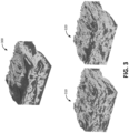
- FIG. 3 illustrates an example computational stratigraphy model representation 300.
- the computational stratigraphy model representation 300 may define subsurface configurations in the physical space.
- the computational stratigraphy model representation 300 may be used as a training image (training data) for modeling to generate subsurface representations 310, 320 in the physical space.
- the subsurface representations 310, 320 may be poor representations of a subsurface region.
- the subsurface representations 310, 320 may be noisy and unstructured compared to the computational stratigraphy model representation 300.
- the subsurface representations 310, 320 may not include small features, such as thin continuous layers.
- the methods and systems of the present disclosure perform modeling within the layer space, rather than the physical space, to generate subsurface representations. While information in the physical space is defined as a function of depth, information in the layer space is defined as a function of layers. Computational stratigraphy model representations and conditioning characteristic(s) in the physical space are converted to the layer space before performing modeling to generate subsurface representations that are both statistically representative as well as physically realistic. Computations of modeling, such as construction and pattern matching, are performed in the layer space, and subsequently subsurface representations are converted from the layer space to the physical space.
- the methods and systems of the present disclosure enable direct simulation of the stratigraphic grids, population of the stratigraphic grids with conditioning characteristics, and generation of subsurface representations that model small-scale continuous layers and maintain physically plausible continuities specified in computational stratigraphy model representations, while jointly honoring conditioning characteristics.
- the methods and systems of the present disclosure solves the challenge of generating representations on non-Cartesian grids by directly simulating the grid itself, and by simultaneously populating the grid with the appropriate properties of interest (e.g., reservoir property) while maintaining the physically plausible continuities specified in the computational stratigraphy model representation and honoring conditioning characteristics (e.g., observed data).
- the electronic storage 13 may be configured to include electronic storage medium that electronically stores information.
- the electronic storage 13 may store software algorithms, information determined by the processor 11, information received remotely, and/or other information that enables the system 10 to function properly.
- the electronic storage 13 may store representation information, information relating to subsurface representations, information relating to subsurface configurations, conditioning information, information relating to conditioning characteristics, information relating to physical space, information relating to layer space, information relating to conversion between physical space and layer space, information relating to modeling, and/or other information.
- the processor 11 may be configured to provide information processing capabilities in the system 10.
- the processor 11 may comprise one or more of a digital processor, an analog processor, a digital circuit designed to process information, a central processing unit, a graphics processing unit, a microcontroller, an analog circuit designed to process information, a state machine, and/or other mechanisms for electronically processing information.
- the processor 11 may be configured to execute one or more machine-readable instructions 100 to facilitate generating subsurface representations.
- the machine-readable instructions 100 may include one or more computer program components.
- the machine-readable instructions 100 may include one or more of a representation information component 102, a conditioning information component 104, a layer space component 106, a modeling component 108, a physical space component 110, and/or other computer program components.
- the representation information component 102 may be configured to obtain representation information and/or other information. Obtaining representation information may include one or more of accessing, acquiring, analyzing, determining, examining, identifying, loading, locating, opening, receiving, retrieving, reviewing, selecting, storing, utilizing, and/or otherwise obtaining the representation information.
- the representation information component 102 may obtain representation information from one or more locations. For example, the representation information component 102 may obtain representation information from a storage location, such as the electronic storage 13, electronic storage of a device accessible via a network, and/or other locations.
- the representation information component 102 may obtain representation information from one or more hardware components (e.g., a computing device, a component of a computing device) and/or one or more software components (e.g., software running on a computing device). Representation information may be stored within a single file or multiple files.
- hardware components e.g., a computing device, a component of a computing device
- software components e.g., software running on a computing device.
- the representation information defines one or more sets of subsurface representations.
- a set of subsurface representations includes multiple subsurface representations.
- a subsurface representation may refer to a computer-generated representation of a subsurface region, such as a one-dimensional, two-dimensional and/or three-dimensional model of the subsurface region.
- a subsurface representation may be defined by and/or include the subsurface configurations simulated by one or more subsurface models.
- a subsurface representation may be used as and/or may be referred to as a digital analog.
- a subsurface region may refer to a part of earth located beneath the surface/located underground.
- a subsurface region may refer to a part of earth that is not exposed at the surface of the ground.
- a subsurface region may be defined in a single dimension (e.g., a point, a line) or in multiple dimensions (e.g., a surface, a volume).
- a subsurface region may include a physical subsurface region, such as a region in the real world, or a virtual subsurface region, such as a subsurface representation generated/simulated using one or more computer models (e.g., computational stratigraphy models).
- a subsurface model may refer to a computer model (e.g., program, tool, script, function, process, algorithm) that generates subsurface representations.
- a subsurface model may simulate one or more subsurface configurations within a region underneath the surface (subsurface region).
- a subsurface model may simulate subsurface configurations by generating one or more subsurface representations.
- a subsurface configuration may refer to attribute, quality, and/or characteristics of a subsurface region.
- a subsurface configuration may refer to physical arrangement of materials (e.g., subsurface elements) within a subsurface region.
- Examples of subsurface configurations simulated by a subsurface model may include types of subsurface materials, characteristics of subsurface materials, compositions of subsurface materials, arrangements/configurations of subsurface materials, physics of subsurface materials, and/or other subsurface configurations.
- a subsurface configuration may include and/or define types, shapes, and/or properties of materials and/or layers that form subsurface (e.g., geological, petrophysical, geophysical, stratigraphic) structures.
- the subsurface model is a computational stratigraphy model.
- a computational stratigraphy model may refer to a computer model that simulates depositional and/or stratigraphic processes on a grain size scale while honoring physics-based flow dynamics.
- a computational stratigraphy model may simulate rock properties, such as velocity and density, based on rock-physics equations and assumptions.
- Input to a computational stratigraphy model may include information relating to a subsurface region to be simulated. For example, input to a computational stratigraphy model may include paleo basin floor topography, paleo flow and sediment inputs to the basin, and/or other information relating to the basin.
- input to a computational stratigraphy model may include one or more paleo geologic controls, such as climate changes, sea level changes, tectonics and other allocyclic controls.
- Output of a computational stratigraphy model may include one or more subsurface configurations and/or one or more subsurface representations.
- a subsurface representation generated by a computational stratigraphy model may be referred to as a computational stratigraphy model representation.
- the computational stratigraphy model includes a forward stratigraphic model.
- a forward stratigraphic model may be fully based on physics of flow and sediment transport.
- a forward stratigraphic model simulates one or more sedimentary processes that recreate the way stratigraphic successions develop and/or are preserved.
- the forward stratigraphic model may be used to numerically reproduce the physical processes that eroded, transported, deposited and/or modified the sediments over variable time periods.
- data may not be used as the anchor points for facies interpolation or extrapolation. Rather, data may be used to test and validate the results of the simulation.
- Stratigraphic forward modelling may be an iterative approach, where input parameters have to be modified until the results are validated by actual data. Usage of other subsurface models and other subsurface representations are contemplated.
- a subsurface representation may define one or more subsurface configurations.
- a subsurface representation defines subsurface configuration(s) in the physical space such that the subsurface configurations are defined as a function of spatial location.
- a subsurface representation defines subsurface configuration(s) in the physical space such that the subsurface configurations are defined as a function of depth.
- a subsurface representation may define different types, shapes, and/or properties of materials and/or layers as a function of depth into the ground and as a function of lateral spatial location.
- the subsurface configurations defined as the function of spatial location may simulate the subsurface configurations that would be seen within a volume (e.g., well, reservoir) in the ground.
- the subsurface configuration e.g., arrangements of subsurface materials and associated properties
- a subsurface representation may be representative of a subsurface region of interest.
- the subsurface configurations defined by a subsurface representation may be representative of the subsurface configurations of a reservoir from which it is desired to generate simulate other subsurface configurations and/or generate other subsurface representations.
- Other types of subsurface settings are contemplated.
- the conditioning information component 104 is configured to obtain conditioning information.
- Obtaining conditioning information may include one or more of accessing, acquiring, analyzing, determining, examining, identifying, loading, locating, opening, receiving, retrieving, reviewing, selecting, storing, utilizing, and/or otherwise obtaining the conditioning information.
- the conditioning information component 104 may obtain conditioning information from one or more locations.
- the conditioning information component 104 may obtain conditioning information from a storage location, such as the electronic storage 13, electronic storage of a device accessible via a network, and/or other locations.
- the conditioning information component 104 may obtain conditioning information from one or more hardware components (e.g., a computing device, a component of a computing device) and/or one or more software components (e.g., software running on a computing device). Conditioning information may be stored within a single file or multiple files.
- conditioning characteristics may refer to subsurface feature, quantity, and/or quality that is desired to be preserved within subsurface representations.
- conditioning characteristics may refer to geological characteristics, geophysical characteristics, and/or other subsurface characteristics.
- Conditioning characteristics may define the guide(s) and/or the fixed point(s) in generating subsurface representations.
- Conditioning characteristics may include subsurface feature, quantity, and/or quality of one or more subsurface points, areas, and/or volumes of interest.
- Conditioning characteristics may be referred to as hard data or fixed data.
- conditioning information may include geological data, petrophysical data, geophysical data, seismic data, and/or other subsurface data (from one or more locations/paths).
- conditioning characteristics may include/reflect the characteristics at one or multiple geographical locations and/or along one or multiple specific paths.
- conditioning characteristics may include one or more rock properties (e.g., rock types, layers, grain sizes, porosity, permeability) that are to be preserved within subsurface representations and/or to be used as guides in generating subsurface representations.
- the rock properties may define fixed points from which subsurface representations are generated. Usage of other subsurface properties as condition characteristics are contemplated.
- the conditioning information defines one or more conditioning characteristics in the physical space such that the conditioning characteristic(s) are defined as the function of depth.
- the conditioning information may define different types, shapes, and/or properties of materials and/or layers as a function of depth at one or more locations (e.g., one or more wells).
- the conditioning information is determined based on one or more well logs obtained from borehole logging and/or interpreted seismic information (including data or data sets).
- the layer space component 106 is configured to convert subsurface data from the physical space to the layer space.
- Subsurface data may refer to data relating to one or more subsurface regions.
- a subsurface data may refer to data relating to physical subsurface region(s) and/or virtual subsurface region(s).
- the layer space component 106 converts subsurface data from the physical space to the layer space before the subsurface data is used in modeling to generate subsurface representations. Conversion of subsurface data from the physical space to the layer space includes change in the vertical dimension used to define the subsurface data. Conversion of subsurface data from the physical space to the layer space includes change in the vertical dimension from depth (distance) into layers. The lateral dimensions of the subsurface data may not be changed by the conversion of the subsurface data between the physical space and the layer space.
- Subsurface data in the physical space may provide and/or define information as a function of depth into the ground.
- subsurface data in the physical space may define different types, shapes, and/or properties of materials and/or layers as a function of depth into the ground.
- Subsurface data in the layer space may provide and/or define information as a function of layers (e.g., rock layers) rather than as a function of depth.
- subsurface data in the layer space may define different types, shapes, and/or properties of materials a function of layers in the ground.
- the subsurface data in the layer space may define thickness of layers (e.g., thickness of sedimentary rock) and other layer properties of interest as a function of layer (and the lateral spatial location).
- the subsurface data in the layer space may define the thickness of sedimentary rock and other rock properties for different layers at any x-y location.
- the layer space component 106 is configured to convert the conditioning information from the physical space to a layer space.
- Conditioning information that defines conditioning characteristic(s) as the function of depth in physical space is converted to the layer space such that the conditioning characteristic(s) are defined as the function of layer.
- the layer space component 106 is configured to convert the set(s) of subsurface representations (e.g., computational stratigraphy model representations) from the physical space to the layer space.
- Subsurface representations that define subsurface configurations as a function of depth in the physical space are converted to the layer space such that the subsurface configurations are defined as a function of layer.
- Information on generation of a subsurface representation (layer-by-layer building based on deposition times by a subsurface model) is used to convert the subsurface representation from the physical space to the layer space.
- conversion of subsurface data from the physical space to the layer space may not include a straight conversion of depth to layer. Rather, conversion of subsurface data from the physical space to the layer space may group subsurface data based on being located within the same layer. Conversion of other subsurface data are contemplated.
- FIG. 4 illustrates an example conversion of subsurface data between the physical space and the layer space.
- FIG. 4 includes a physical space representation 410 of a subsurface region in the physical space and a layer space representation 420 of the subsurface region in the layer space.
- the vertical dimension of the physical space representation 410 in the physical space may be depth (distance).
- the subsurface configurations of the subsurface region may be defined as a function of depth under the ground.
- the subsurface region in the physical space may include layers 412, 414, 416.
- the layers 412, 414, 416 may include rocks layers that are arranged on top of one another.
- the layers 412, 414, 416 may have been deposited at different times.
- the layers 412, 414, 416 may be divided into cells 418.
- the vertical dimension of the layer space representation 420 of subsurface region in the layer space may be layers.
- the subsurface configurations of the subsurface region may be defined as a function of layer, instead of depth.
- the layer space representation 420 may include the subsurface region divided/separated in area-layer rather than area-depth as shown in the physical space representation 410.
- the subsurface region in the layer space may include layers 422, 424, 426 (e.g., computational stratigraphy model grid layers).
- the layers 422, 424, 426 may be divided into cells 428.
- the layer 422 may correspond to the layer 412
- the layer 424 may correspond to the layer 414
- the layer 426 may correspond to the layer 416.
- the corresponding upper right cell in the layer space representation 420 is larger, making the computation becomes easier to perform in the layer space compared to in the physical space.
- conversion of the subsurface data from the physical space to the layer space may facilitate modeling to generate subsurface representations. Conversion of the subsurface representation from the layer space to the physical space may result in the subsurface representation simulating how the corresponding subsurface region would appear in the real world.
- one or more computational stratigraphy model representations in the layer space may define the subsurface configurations using cells within individual computational stratigraphy model grid layers.
- a cell within individual computational stratigraphy model grid layer may be used to convey information relating to the corresponding portion of the subsurface configurations.
- the cells may be characterized by a cell thickness, one or more properties of interest, and/or other information.
- the propert(ies) of interest may include a grain size, a grain type, a grain lithology, a porosity, a permeability, and/or other propert(ies).
- the propert(ies) of interest may include one or more geological, petrophysical, geophysical, and/or stratigraphic properties.
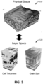
- FIG. 5 illustrates an example conversion of a subsurface representation (digital analog) between the physical space and the layer space.
- FIG. 5 includes a physical space representation 510 of a computational stratigraphy model representation in the physical space and a layer space representation 520 of the computational stratigraphy model representation in the layer space.
- the vertical dimension of the physical space representation 510 of the computational stratigraphy model representation in the physical space may be depth (distance) and the vertical dimension of the layer space representation 520 of the computational stratigraphy model representation in the layer space may be layers.
- the physical space representation 510 and/or the layer space representation 520 may be divided into cells.
- the layer space representation 520 of the computational stratigraphy model representation in the layer space may include multiple representations to define different properties of the computational stratigraphy model representation. For a given computational stratigraphy model representation (denoted by superscript DA), conversion into the layer space may result in representations that define stratigraphic cell thicknesses and the corresponding subsurface properties of interest for individual cells V 1 DA , V 2 DA , ... , V n p DA .
- layer space representation 520 of the computational stratigraphy model representation in the layer space may include a representation of cell thickness and a representation of grain size. Representations for other properties of interest (e.g., porosity, permeability) are contemplated.
- the computational stratigraphy model representation in the physical space may not perform well as training images in modeling due to non-uniform cell thicknesses. Conversion of the computational stratigraphy model representation from the physical space to the layer space may result in layers of differing thicknesses and shapes being represented by uniform layers. Thus, conversion of the computational stratigraphy model representation from the physical space to the layer space may facilitate modeling to generate subsurface representations. Conversion of the computational stratigraphy model representation from the layer space to the physical space may result in the computational stratigraphy model representation simulating how the corresponding subsurface region (e.g., subsurface configurations of the subsurface region) would appear in the real world.
- subsurface region e.g., subsurface configurations of the subsurface region
- the modeling component 108 is configured to perform modeling within the layer space based on subsurface data in the layer space. The modeling is performed to generate multiple subsurface representations.
- modeling component 108 is configured to perform modeling within the layer space based on the set(s) of subsurface representations (e.g., computational stratigraphy model representation) within the layer space and the conditioning characteristic(s) within the layer space to generate multiple subsurface representations within the layer space.
- the modeling component 108 uses the subsurface configurations and conditioning characteristics defined as a function of layer (and as a function of lateral spatial location) to generate subsurface representations within the layer space.
- the modeling component 108 may use conditioning characteristics to determine which portions of the subsurface configurations will be included within the subsurface representation.
- Modeling may refer to simulation of subsurface configurations using one or more subsurface models to building probable/equiprobable subsurface representations.
- the subsurface representation may be generated for a particular subsurface region, for a particular moment in time, and/or for a duration of time (e.g., simulation of how subsurface configurations change within a subsurface region over time).
- Modeling may generate one or more detailed subsurface representations using sparse data (e.g., conditioning characteristic(s) from well log(s)/well core(s)) and information relating to depositional systems (e.g., computational stratigraphy model representation(s)) to estimate subsurface characteristics (e.g., around well(s) and/or between wells).
- modeling may be used to generate one or more subsurface representations of a reservoir based on conditioning characteristics from one or more wells of interest.
- Modeling e.g., geostatistical modeling, stochastic simulation
- modeling may be performed to populate the properties associated with each location on individual layer surfaces.
- the properties may include layer thickness.
- the properties may include other subsurface properties, such mean grain size for the deposited sediments, sorting of the grain size distribution of the deposited sediments, porosity and permeability, and/or other subsurface properties.
- Performing modeling within the layer space may facilitate generation of subsurface representations that model small-scale continuous layers and maintain physically plausible continuities of the subsurface representations (e.g., computational stratigraphy model representations), while jointly honoring conditioning characteristics.
- Layer space may enable use of modeling that handle both continuous and discrete variables.
- Performing modeling within the layer space may enable simulation of both subsurface structures and properties.
- Simulation of subsurface configurations within the layer space may enable simulation of both continuous and discrete properties, overcoming the deficiencies of existing multi-point statistics techniques that are limited to discrete properties.
- Simulation of the subsurface structures and the properties may be performed concurrently to avoid correlation issues.
- geostatistical modeling of petrophysical properties may be performed concurrently with structure generation. Such geostatistical modeling may require use of a multivariate geostatistical algorithm, such as the algorithm disclosed herein. Algorithms that perform subsurface structure and properties simulation sequentially may not be able to properly maintain property-structure correlations.
- the modeling may be performed using one or more multi-point statistics techniques and/or other techniques.
- a multi-point statistics technique may refer to a facies modeling technique based on multiple-point statistics.
- a multi-point statistics technique may enable modeling of complex and heterogeneous subsurface configurations through use of one or more training images, which describe subsurface characteristics of the facies to model.
- one or more computational stratigraphy model representations/one or more sets of computational stratigraphy model representations may be used as a set of training images in the multi-point statistics technique.
- a multi-point statistics technique performed within the layer space may handle multivariate continuous variables.
- a multi-point statistics technique performed within the layer space may be based on fast Fourier transform and may be computationally efficient.
- the subsurface representations generated through modeling within the layer space include regions of the subsurface configurations defined by the set(s) of subsurface representations (e.g., computational stratigraphy model representations).
- the regions of the subsurface configurations defined by the set(s) of subsurface representations may be included within the newly generated subsurface representation(s) based on the conditioning characteristic(s) and/or other information.
- Regions of the subsurface configurations defined by the set(s) of subsurface representations may refer to areas or portions of the subsurface configurations defined by one or more subsurface representations within the set(s) of subsurface representations.
- Modeling may be used to identify regions of the subsurface configurations to be included within a subsurface representation based on one or more conditioning characteristics.
- Regions of the subsurface configurations identified for inclusion within a subsurface representation may include subsurface configurations that honor (e.g., preserves, simulates) the conditioning characteristics within the subsurface representation.
- performance of the modeling may include, for an individual subsurface representation, generation of a simulation domain to define one or more properties of interest and a cell thickness for individual cells.
- Generation of a simulation domain may include specifying a simulation domain of size.
- a simulation domain may include one or more simulation/computation grids on which the modeling is performed.
- the simulation domain may include a multivariate grid used to define individual properties of interest (e.g., reservoir properties) in addition to cell thickness.
- the simulation domain may be populated with the conditioning characteristic(s).
- the simulation domain may be populated at corresponding spatial locations with the conditioning characteristic(s). That is, the conditioning characteristics may be inserted into the simulation domain in their corresponding locations based on the locations of the conditioning characteristics in the layer space.
- the simulation domain may be partitioned into tiles, with individual tiles having a core region and a peripheral region.
- the simulation domain may be partitioned into tiles of equal sizes.
- the tile size may need not be a factor of the simulation grid size.
- a core region may be included within a tile.
- a core region may refer to a core portion of a tile.
- a core region may include the portion of the tile that is to be filled based on conditioning characteristics within the core region and/or based on continuity with neighboring tiles (as determined through the peripheral region).
- a peripheral region may be included within a tile or located outside the tile.
- a peripheral region may include one or more portions of the tile that surround the core region and extend to edges of the tile.
- a peripheral region may include one or more areas outside the tile that surround the edges of the tile. At least some of the peripherical region of an individual tile may overlap with the core region of one or more neighboring tiles. That is, individual tiles within the simulation domain may define a core region and a peripheral region that may overlap with neighboring tile(s). Individual tile's core region may be assigned a region of the simulation domain, while the peripheral region may coincide with the core region of one or more neighboring tiles.
- the tiles may include a set of partially populated tiles and a set of unpopulated tiles.
- a partially populated tile may refer to a tile that includes/is populated with at least one of the conditioning characteristic(s).
- the set of partially populated tiles may include one or more partially populated tiles populated with at least one of the conditioning characteristic(s).
- An unpopulated tile may refer to a tile that does not include/is not populated with any conditioning characteristics.
- the set of unpopulated tiles may include one or more unpopulated tiles not populated with any of the conditioning characteristic(s).
- individual partially populated tiles may be filled based on partially populated tile matching regions of the subsurface configurations and/or other information.
- Partially populated tile matching regions may be determined based on matching with the conditioning characteristic(s) within the individual tiles and/or other information.
- the conditioning characteristic(s) within a tile may represent data points that need to be matched/is sought to be matched within the subsurface configurations of the computational stratigraphy model representations.
- a partially populated tile matching region of the subsurface configurations may refer to a region of the subsurface configurations that matches the conditioning characteristic(s) within a partially populated tile.
- a region of the subsurface configurations may match the conditioning characteristic(s) within a partially populated tile based on the region of the subsurface configurations having the same or similar (within a threshold value) subsurface characteristic(s) as the conditioning characteristic(s) within the partially populated tile.
- the subsurface configurations of the subsurface representation(s) e.g., computational stratigraphy model representation(s)
- the partially populated tile may be filed with and/or based on the partially populated tile matching regions of the subsurface configurations determined based on the conditioning characteristic(s) within the partially populated tile.
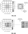
- FIG. 6A illustrates example tiles within a simulation domain and example overlap regions (peripheral region) when filling the center tile based on conditioning characteristics/hard data (grain size).
- the conditioning characteristic(s) (hard data) within a partially populated tile may be used to fill the partially populated tile with the region of the subsurface configurations that will honor the conditioning characteristic(s) within the partially populated tile.
- the region of the subsurface representation e.g., computational stratigraphy model representation
- the region of the subsurface representation with the matching region of the subsurface configurations may be extracted to fill the partially populated tile.
- the region of the subsurface representation with the matching region of the subsurface configurations may be used to fill the partially populated tile.
- region of the subsurface representation with the matching region of the subsurface configurations may be modified before being used to fill the partially
- filling of the partially populated tile with/based on the determined region of the subsurface configurations may include filling of the core region and the peripheral region of the partially populated tile. That is, both the core region and the peripheral region of the partially populated tile may be filled with/based on the tile matching region of the subsurface configurations. The peripheral region of the partially populated tile may be filled with/based on the corresponding portion of the determined region of the subsurface configurations.
- filling of the partially populated tile with/based on the determined region of the subsurface configurations may include filling of the core region of the partially populated tile without filling of the peripheral region of the partially populated tile. That is, the peripheral region of the partially populated tile may not be filled with/based on the tile matching region of the subsurface configurations when filling the core region of the partially populated tile.
- a partially populated tile may be filled further based on one or more neighboring tiles that have been previously filled.
- a neighboring tile of a tile may refer to an adjacent tile of the tile.
- a neighboring tile of a tile may share one or more edges of the tile.
- a neighboring tile of a tile e.g., square
- a neighboring tile of a tile may include tiles that are above, below, to the right, and/or to the left of the tile.
- a neighboring tile of a tile e.g., cube
- a neighboring tile of a tile may share one or more points of the tile.
- a neighboring tile of a tile may include tiles that are above, below, to the right, to the left, and/or at corner/diagonal to the tile.
- a neighboring tile of a tile may include tiles that are above, below, to the right, to the left, in front of, behind, at upper-right front corner, at upper-right rear corner, at upper-left front corner, at upper-left rear corner, at lower-right front corner, at lower-right rear corner, at lower-left front corner, and/or at lower-left rear corner of the tile.
- Filling a partially populated tile further based on previously filled neighboring tile(s) may include determining the partially populated tile matching region of the subsurface configurations further based on one or more portions of the filled neighboring tile(s).
- the partially populated tile region may be determined so that the subsurface characteristics of the partially populated tile region that overlaps with the previously filled neighboring tile(s) has the same or similar (within a threshold value) subsurface characteristics as the overlapping portion of the previously filled neighboring tile(s).
- a core region of a neighboring tile may have been previously filled, and the partially populated tile matching region of the subsurface configuration may be determined based on the prior filling of the neighboring tile's core region so that the peripheral region of the partially populated tile matching region (that overlaps with the neighboring tile's core region) has the same or similar (within a threshold value) subsurface characteristics as the overlapping portion of core region of the neighboring tile.
- a peripheral region of a neighboring tile may have been previously filled, and the partially populated tile matching region of the subsurface configuration may be determined based on the prior filling of the neighboring tile's peripheral region that overlaps with the tile being filled so that the core region of the partially populated tile matching region (that overlaps with the neighboring tile's peripheral region) has the same or similar (within a threshold value) subsurface characteristics as the overlapping portion of peripheral region of the neighboring tile.
- filling of a partially populated tile may take into account both the conditioning characteristic(s) within the partially populated tile, as well as the overlap with the previously filled neighboring tile(s).
- FIG. 6B illustrates example tiles within a simulation domain and example overlap regions when filling in tiles that have a previously filled neighboring tile. Overlap regions within multiple previously filled neighboring tiles may be used to fill a partially populated tile.
- separate cross correlation maps may be computed for individual overlaps, and appropriate translations may be applied such that they coincide and then are stacked and summed.
- Use of the overlap with previously filled tile(s) may enable generation of subsurface representations that maintains continuity of subsurface configurations within the simulation and/or continuity between neighboring tiles.
- Use of the overlap with previously filled tile(s) to fill a partially populated tile may effectuate/simulate use of a sliding window to fill the partially populated tile.
- subsurface characteristics within the overlapping portions of neighboring tiles may be modified to increase continuity between the tiles. For example, subsurface characteristics within the overlapping portions of neighboring tiles may be blended to minimize discontinuities between neighboring tiles.
- a boundary cutting technique may be used to maintain continuity of subsurface configurations within adjacent tiles. A boundary cutting technique may apply optimal boundary to minimize discontinuities between tiles.
- a sampled tile's left overlap may not match the previous tile's right target overlap.
- Optimal boundary may be applied to minimize the discontinuity, where content of the tile to the left of the boundary may be set to target overlap, and content of the tile to the right of the boundary may be matched overlap.
- Use of the overlap with previously filled tile(s) may enable generation of subsurface representations that maintain physically plausible continuities of the subsurface representations (e.g., computational stratigraphy model representations).
- the partially populated tile matching regions may be determined further based on a continuity score between a search template in the layer space (comprised of conditioning data) and one or more subsurface representations (e.g., computational stratigraphy model representation(s), a set of computational stratigraphy model representations) in the layer space.
- a search template may refer to a set of points that are organized systematically and used for finding similar patterns in the subsurface representations (training images). For example, for individual partially populated tiles, a search template may be constructed for finding the (optimal) locations on the subsurface representations to extract the subsurface configurations.
- the continuity score between the search template and the subsurface representation may be computed. This may be quantified using the (1) sum of square differences (SSD) and normalized cross correlation (NCC).
- the continuity score at location x on the subsurface representation may be weighted sum of these two measures for individual properties of interest.
- the weight may be chosen to emphasis continuity for a property.
- the following may be performed: (1) Hessian blob detection may be performed to identify regions of high match; (2) a weighted randomized sampling (weighed by maximum continuity cost map value in each blob) may be performed to select a single location x *; (3) the region of the subsurface representation that corresponds to the x * denoted S DA * may be extracted; (4) S DA * may be compared to S ijk and patching blending may be performed to S DA * (i.e. Gaussian blending) to ensure that they are consistent where I ijk ⁇ 0.
- the blended S DA * may be copied onto the simulation domain. This process (starting from construction of a search template) may be repeated until all partially populated tiles are filled.
- individual unpopulated tiles may be filled based on unpopulated tile matching regions of the subsurface configurations and/or other information.
- An unpopulated tile matching region may be determined based on continuity with one or more neighboring tiles and/or other information. Continuity with the neighboring tile(s) may be determined based on overlap between peripheral regions of neighboring tiles and core of the unpopulated tile. Overlaps between an unpopulated tile with neighboring tile(s) that have been previously filled may represent areas of data points that need to be matched using the subsurface configurations of the computational stratigraphy model representations.
- An unpopulated tile matching region of the subsurface configurations may refer to a region of the subsurface configurations that matches the subsurface characteristic(s) within overlapping regions of neighboring tile(s).
- a region of the subsurface configurations may match the subsurface characteristic(s) within overlapping regions of neighboring tile(s) based on the region of the subsurface configurations having the same or similar (within a threshold value) subsurface characteristic(s) as the overlapping regions of neighboring tile(s).
- the subsurface configurations of the subsurface representation(s) e.g., computational stratigraphy model representation(s)
- the unpopulated tile may be filed with and/or based on the unpopulated tile matching regions of the subsurface configurations determined based on continuity with neighboring tile(s).
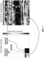
- FIG. 7 illustrates an example insertion of a portion of subsurface configurations in the layer space into a simulation domain based on continuity with a previously filled (simulated) neighboring tile.
- a portion of the subsurface configurations may be determined as an unpopulated tile matching region for assignment as the next (adjacent) tile based on the portion of the subsurface configurations being able to maintain continuity with the previously filled neighboring tile.
- the continuity of the tiles may be used to fill the unpopulated tile with the region of the subsurface configurations that will maintain physically plausible continuities of the subsurface representation (e.g., computational stratigraphy model representation).
- the region of the subsurface representation with the matching region of the subsurface configurations may be extracted to fill the unpopulated tile.
- the region of the subsurface representation with the matching region of the subsurface configurations may be used to fill the unpopulated tile.
- region of the subsurface representation with the matching region of the subsurface configurations may be modified before being used to fill the unpopulated tile.
- FIG. 6A, FIG. 6B , and FIG. 7 are in two-dimensions, this is merely as an example and is not meant to be limiting.
- the simulation domain may be partitioned into two-dimensional and/or three-dimensional tiles, and tile matching/filling may be performed in two-dimensions and/or three-dimensions.
- individual partially populated tiles may be filled prior to filling of individual unpopulated tiles (tiles with no data). That is, partially populated tiles may be prioritized in filling order so that they are filled with matching regions of the subsurface configurations prior to filling of unpopulated tiles. Such filling of tiles may prioritize conditioning characteristics within the simulation domain in generating subsurface representations.
- An order in which the individual unpopulated tiles are filled may be determined based on a raster path and/or other information.
- the raster path may prioritize in the order the unpopulated tiles adjacent to one or more of the populated tiles (tiles that have been filled and have peripheral data that surrounding unpopulated tiles must take into account) over the unpopulated tiles not adjacent to any of the populated tiles.
- Such filing of tiles may prioritize regions near conditioning characteristics within the simulation domain in generating subsurface representations.
- one or more morphological dilations may be applied to the simulation domain, where tiles filled in previous step (those containing conditioning characteristic(s)) are 1 and empty tiles are 0.
- the morphological structuring element may be a cube (e.g., 3x3 cube). Individual empty tiles that are dilated may be stored into a list (the raster path). This process may be repeated until the dilation covers the entire simulation domain.
- the rather path may contain the order in which unpopulated tiles should be filled to ensure that unpopulated tiles surrounding conditioning characteristics are filled prior to other unpopulated tiles.
- J ijk ( x ) may be used and a single location x * may be sampled as describe above, and S DA * may be extracted; (3) S DA * may be compared to S ijk , and the (optimal) boundary cut within I ijk ⁇ 0 may be found that would allow the two tiles to be stitched together while maximizing continuity. In some implementations, this may be accomplished by using one or more shortest path algorithms, such as Dijkstra's algorithm, on the
- shortest path algorithms such as Dijkstra's algorithm
- FIGS. 8A and 8B illustrate an example flow diagram (split into parts 800A, 800B) including steps to generate subsurface representations within the layer space.
- Random sampling of tiles from locations with high correlations may enable generation of multiple subsurface representations. If only locations with maximum correlations are sampled for insertion in the simulation domain, different subsurface representations may contain only small differences. This may be due to the subsurface representations being generated from entire chunks of computational stratigraphy model representation being inserted into the simulation domain. Random sampling of tiles from locations with high correlations may be used to create variability between different subsurface representations.
- the physical space component 110 is configured to convert the subsurface representations from the layer space to the physical space.
- the subsurface representations are back-transformed to the physical space.
- the subsurface representations in the layer space define subsurface data (e.g., subsurface configurations) as a function of layers (and lateral spatial location), and conversion of the subsurface representations into the physical space results in the subsurface representations defining subsurface data as a function of depth (and lateral spatial location). Conversion of the subsurface representations from the layer space to the physical space results in the subsurface representations simulating how the subsurface region would appear in the real world.
- a subsurface representation may be converted from the layer space to the physical space based on cell thicknesses, propert(ies) of interest, and/or other information.
- a subsurface representation may be converted from the layer space to the physical space by taking the cumulative sum of the cell thicknesses in the z-direction and populating individual cells with the simulated propert(ies) of interest (e.g., simulated reservoir property).
- the subsurface representation(s) generated as described herein in the layer space and converted into the physical space may model small-scale continuous layers and maintain physically plausible continuities of the set(s) of computational stratigraphy model representations, while jointly honoring the conditioning characteristic(s).
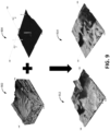
- FIG. 9 illustrates example inputs and outputs of the subsurface representation generation algorithm as disclosed herein.
- the inputs to the subsurface representation generation algorithm may include a computational stratigraphy model representation 902 and conditioning data 904.
- the conditioning data 904 may include subsurface data for three separate wells. Use of other number of wells are contemplated.
- the computational stratigraphy model representation 902 (three-dimensional training image) may provide rich digital analogs of depositional environments, and one or more subsurface representations that preserves the conditioning data 904 in their corresponding locations may be generated.
- two separate subsurface representations 912, 914 may be generated from the computational stratigraphy model representation 902 and the conditioning data 904.
- the simulation grid may be half of the size of the training image.
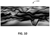
- FIG. 10 illustrates an example two-dimensional image 1000 (e.g., cross-sectional image) of a computational stratigraphy model representation.
- the two-dimensional image 1000 may be used as a training image for modeling.
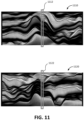
- FIG. 11 illustrate two separate two-dimensional subsurface representations 1110, 1120 generated from the two-dimensional image 1000.
- the two-dimensional subsurface representations 1110, 1120 may include two-dimensional slices of three-dimensional subsurface representations generated from the computational stratigraphy model representation.
- Areas 1112, 1122 of the two-dimensional subsurface representations 1110, 1120 may include/preserve conditioning data. As shown in FIG. 11 , the conditioning data may be included/preserved within the areas 1112, 1122 of the subsurface representations 1110, 1120.
- Other areas of the subsurface representations 1110, 1120 may differ from each other. The variations in different subsurface representations may capture different possibilities of structural configurations.
- Implementations of the disclosure may be made in hardware, firmware, software, or any suitable combination thereof. Aspects of the disclosure may be implemented as instructions stored on a machine-readable medium, which may be read and executed by one or more processors.
- a machine-readable medium may include any mechanism for storing or transmitting information in a form readable by a machine (e.g., a computing device).
- a tangible computer-readable storage medium may include read-only memory, random access memory, magnetic disk storage media, optical storage media, flash memory devices, and others
- a machine-readable transmission media may include forms of propagated signals, such as carrier waves, infrared signals, digital signals, and others.
- Firmware, software, routines, or instructions may be described herein in terms of specific exemplary aspects and implementations of the disclosure and performing certain actions.
- External resources may include hosts/sources of information, computing, and/or processing and/or other providers of information, computing, and/or processing outside of the system 10.
- any communication medium may be used to facilitate interaction between any components of the system 10.
- One or more components of the system 10 may communicate with each other through hard-wired communication, wireless communication, or both.
- one or more components of the system 10 may communicate with each other through a network.
- the processor 11 may wirelessly communicate with the electronic storage 13.
- wireless communication may include one or more of radio communication, Bluetooth communication, Wi-Fi communication, cellular communication, infrared communication, or other wireless communication. Other types of communications are contemplated by the present disclosure.
- the processor 11 is shown in FIG. 1 as a single entity, this is for illustrative purposes only. In some implementations, the processor 11 may comprise a plurality of processing units. These processing units may be physically located within the same device, or the processor 11 may represent processing functionality of a plurality of devices operating in coordination. The processor 11 may be separate from and/or be part of one or more components of the system 10. The processor 11 may be configured to execute one or more components by software; hardware; firmware; some combination of software, hardware, and/or firmware; and/or other mechanisms for configuring processing capabilities on the processor 11.
- computer program components are illustrated in FIG. 1 as being co-located within a single processing unit, one or more of computer program components may be located remotely from the other computer program components. While computer program components are described as performing or being configured to perform operations, computer program components may comprise instructions which may program processor 11 and/or system 10 to perform the operation.
- While computer program components are described herein as being implemented via processor 11 through machine-readable instructions 100, this is merely for ease of reference and is not meant to be limiting. In some implementations, one or more functions of computer program components described herein may be implemented via hardware ( e.g ., dedicated chip, field-programmable gate array) rather than software. One or more functions of computer program components described herein may be software-implemented, hardware-implemented, or software and hardware-implemented .
- processor 11 may be configured to execute one or more additional computer program components that may perform some or all of the functionality attributed to one or more of computer program components described herein.
- the electronic storage media of the electronic storage 13 may be provided integrally (i.e ., substantially non-removable) with one or more components of the system 10 and/or as removable storage that is connectable to one or more components of the system 10 via, for example, a port ( e.g ., a USB port, a Firewire port, etc. ) or a drive ( e.g., a disk drive, etc. ) .
- the electronic storage 13 may include one or more of optically readable storage media (e.g., optical disks, etc. ) , magnetically readable storage media (e.g ., magnetic tape, magnetic hard drive, floppy drive, etc.
- the electronic storage 13 may be a separate component within the system 10, or the electronic storage 13 may be provided integrally with one or more other components of the system 10 ( e .g., the processor 11). Although the electronic storage 13 is shown in FIG. 1 as a single entity, this is for illustrative purposes only. In some implementations, the electronic storage 13 may comprise a plurality of storage units. These storage units may be physically located within the same device, or the electronic storage 13 may represent storage functionality of a plurality of devices operating in coordination.
- FIG. 2 illustrates method 200 for generating subsurface representations.
- the operations of method 200 presented below are intended to be illustrative. In some implementations, method 200 may be accomplished with one or more additional operations not described, and/or without one or more of the operations discussed. In some implementations, two or more of the operations may occur substantially simultaneously.
- method 200 may be implemented in one or more processing devices (e.g ., a digital processor, an analog processor, a digital circuit designed to process information, a central processing unit, a graphics processing unit, a microcontroller, an analog circuit designed to process information, a state machine, and/or other mechanisms for electronically processing information).
- the one or more processing devices may include one or more devices executing some or all of the operations of method 200 in response to instructions stored electronically on one or more electronic storage media.
- the one or more processing devices may include one or more devices configured through hardware, firmware, and/or software to be specifically designed for execution of one or more of the operations of method 200.
- representation information is obtained.
- the representation information defines a set of computational stratigraphy model representations.
- the set of computational stratigraphy model representations defines subsurface configurations in a physical space such that the subsurface configurations are defined as a function of depth.
- operation 202 may be performed by a processor component the same as or similar to the representation information component 102 (Shown in FIG. 1 and described herein).
- conditioning information is obtained.
- the conditioning information defines one or more conditioning characteristics in the physical space such that the conditioning characteristic(s) are defined as the function of depth.
- operation 204 may be performed by a processor component the same as or similar to the conditioning information component 104 (Shown in FIG. 1 and described herein).
- the set of computational stratigraphy model representations is converted from the physical space to a layer space such that the subsurface configurations are defined as a function of layers.
- operation 206 may be performed by a processor component the same as or similar to the layer space component 106 (Shown in FIG. 1 and described herein).
- the conditioning information is converted from the physical space to the layer space such that the conditioning characteristic(s) are defined as the function of layers.
- operation 208 may be performed by a processor component the same as or similar to the layer space component 106 (Shown in FIG. 1 and described herein).
- modeling is performed within the layer space based on the set of computational stratigraphy model representations within the layer space and the conditioning characteristic(s) within the layer space to generate multiple subsurface representations within the layer space.
- the subsurface representations include regions of the subsurface configurations based on the conditioning characteristic(s) .
- operation 210 may be performed by a processor component the same as or similar to the modeling component 108 (Shown in FIG. 1 and described herein).
- operation 212 the subsurface representations are converted from the layer space to the physical space.
- operation 212 may be performed by a processor component the same as or similar to the physical space component 110 (Shown in FIG. 1 and described herein).
Landscapes
- Physics & Mathematics (AREA)
- Engineering & Computer Science (AREA)
- General Physics & Mathematics (AREA)
- Computer Graphics (AREA)
- Geometry (AREA)
- Software Systems (AREA)
- Theoretical Computer Science (AREA)
- Life Sciences & Earth Sciences (AREA)
- General Life Sciences & Earth Sciences (AREA)
- Geophysics (AREA)
- Processing Or Creating Images (AREA)
- Management, Administration, Business Operations System, And Electronic Commerce (AREA)
Claims (12)
- Computer-implementiertes Verfahren (200) zum Erzeugen von Darstellungen eines Untergrunds, wobei das computer-implementierte Verfahren (200) Folgendes umfasst:Erhalten (202) von Darstellungsinformationen, wobei die Darstellungsinformationen eine Gruppe von Computerstratigraphiemodell-Darstellungen definieren, wobei die Gruppe von Computerstratigraphiemodell-Darstellungen Untergrundkonfigurationen in einem physikalischen Raum definieren, derart, dass die Untergrundkonfigurationen als eine Funktion der Tiefe definiert werden, wobei die Gruppe von Computerstratigraphiemodell-Darstellungen Schicht für Schicht unter Verwendung eines vorwärts gerichteten Stratigraphiemodells, das einen oder mehrere Sedimentierungsprozesse simuliert, erzeugt werden;Erhalten (204) von Konditionierungsinformationen, wobei die Konditionierungsinformationen eine oder mehrere Konditionierungseigenschaften im physikalischen Raum definieren, derart, dass die eine oder die mehreren Konditionierungseigenschaften als eine Funktion der Tiefe definiert werden, wobei die eine oder die mehreren Konditionierungseigenschaften auf der Grundlage einer oder mehrerer Bohrlochmessungen bestimmt werden, die aus einer Bohrlochuntersuchung und/oder aus interpretierten seismischen Informationen erhalten werden;Umsetzen (206) der Gruppe von Computerstratigraphiemodell-Darstellungen aus dem physikalischen Raum in einen Schichtraum, derart, dass die Untergrundkonfigurationen als eine Funktion von Schichten definiert werden, wobei die Gruppe von Computerstratigraphiemodell-Darstellungen auf der Grundlage der Erzeugung Schicht für Schicht der Gruppe von Computerstratigraphiemodell-Darstellungen durch das vorwärts gerichtete Stratigraphiemodell aus dem physikalischen Raum in den Schichtraum umgesetzt werden;Umsetzen (208) der Konditionierungsinformationen aus dem physikalischen Raum in den Schichtraum, derart, dass die eine oder die mehreren Konditionierungseigenschaften als die Funktion der Schichten definiert werden;Durchführen einer Modellierung (210) im Schichtraum auf der Grundlage der Gruppe von Computerstratigraphiemodell-Darstellungen im Schichtraum und der einen oder den mehreren Konditionierungseigenschaften im Schichtraum, um mehrere Untergrunddarstellungen im Schichtraum zu erzeugen, wobei die mehreren Untergrunddarstellungen Bereiche der Untergrundkonfigurationen enthalten, die durch die Gruppe von Computerstratigraphiemodell-Darstellungen auf der Grundlage der einen oder der mehreren Konditionierungseigenschaften definiert werden, wobei die Leistung der Modellierung im Schichtraum die gleichzeitige Simulation sowohl von Untergrundstrukturen als auch von Untergrundeigenschaften unter Verwendung der Bereiche der Untergrundkonfigurationen, die durch die Gruppe von Computerstratigraphiemodell-Darstellungen definiert werden, enthält, wobei die mehreren Untergrunddarstellungen auf eine Weise erzeugt werden, dass sie verschiedene Untergrundstrukturen und Untergrundeigenschaften enthalten, derart, dass die mehreren Untergrunddarstellungen verschiedene Untergrundkonfigurationen definieren; undUmsetzen (212) der mehreren Untergrunddarstellungen aus dem Schichtraum in den physikalischen Raum.
- Verfahren (200) nach Anspruch 1, wobei das Modellieren (210) unter Verwendung einer Mehrpunkt-Statistik-Technik durchgeführt wird.
- Verfahren (200) nach Anspruch 2, wobei die Gruppe von Computerstratigraphiemodell-Darstellungen als eine Gruppe von Trainingsbildern in der Mehrpunkt-Statistiktechnik verwendet wird.
- Verfahren (200) nach Anspruch 1, wobei die Gruppe von Computerstratigraphiemodell-Darstellungen im Schichtraum die Untergrundkonfigurationen unter Verwendung von Zellen in einzelnen Computerstratigraphiemodell-Rasterschichten definiert, wobei die Zellen durch eine Zellendicke und/oder durch eine oder mehrere Eigenschaften von Interesse beschrieben werden.
- Verfahren (200) nach Anspruch 4, wobei die eine oder die mehreren Eigenschaften von Interesse eine Korngröße, eine Kornart, eine Kornlithologie, eine Porosität und/oder eine Durchlässigkeit enthalten.
- Verfahren (200) nach Anspruch 1, wobei die Ausführung der Modellierung Folgendes umfasst:für eine einzelne Untergrunddarstellung, Erzeugen einer Simulationsdomäne, um eine oder mehrere Eigenschaften von Interesse und eine Zellendicke für einzelne Zellen zu definieren;Befüllen der Simulationsdomäne mit der einen oder den mehreren Konditionierungseigenschaften;Unterteilen der Simulationsdomäne in Kacheln, wobei einzelne Kacheln einen Kernbereich und einen Randbereich aufweisen, wobei zumindest ein Anteil des Randbereichs einer einzelnen Kachel mit dem Kernbereich einer benachbarten Kachel überlappt, wobei die Kacheln ferner eine Gruppe teilweise befüllter Kacheln und eine Gruppe nicht befüllter Kacheln enthalten, wobei die Gruppe teilweise befüllter Kacheln eine oder mehrere teilweise befüllte Kacheln, die mit mindestens einer der einen oder der mehreren Konditionierungseigenschaften befüllt sind, enthält, und die Gruppe nicht befüllter Kacheln eine oder mehrere nicht befüllte Kacheln, die mit keiner der einen oder der mehreren Konditionierungseigenschaften befüllt sind, enthält;Auffüllen einzelner teilweise befüllter Kacheln auf der Grundlage von Bereichen mit übereinstimmenden teilweise befüllten Kacheln der Untergrundkonfigurationen, wobei die Bereiche mit übereinstimmenden teilweise befüllten Kacheln auf der Grundlage einer Übereinstimmung mit der einen oder den mehreren Konditionierungseigenschaften in den einzelnen teilweise befüllten Kacheln bestimmt werden; undAuffüllen einzelner nicht befüllter Kacheln auf der Grundlage von Bereichen mit übereinstimmenden nicht befüllten Kacheln der Untergrundkonfigurationen, wobei die Bereiche mit übereinstimmenden nicht befüllten Kacheln auf der Grundlage einer Kontinuität mit einer oder mehreren benachbarten Kacheln bestimmt werden;wobei die einzelnen teilweise befüllten Kacheln vor dem Auffüllen der einzelnen nicht befüllten Kacheln aufgefüllt werden.
- Verfahren (200) nach Anspruch 6, wobei die Bereiche mit übereinstimmenden teilweise befüllten Kacheln ferner auf der Grundlage einer Kontinuitätsbewertung zwischen einer Suchvorlage im Schichtraum und einer Computerstratigraphiemodell-Darstellung im Schichtraum bestimmt werden, und wobei die Kontinuitätsbewertung wahlweise als eine gewichtete Summe einer normierten Kreuzkorrelation (NCC) und einer Summe (SSD) der quadrierten Differenzen für einzelne Eigenschaften von Interesse berechnet wird.
- Verfahren (200) nach Anspruch 6, wobei eine Reihenfolge, in der die einzelnen nicht befüllten Kacheln aufgefüllt werden, auf der Grundlage eines Rasterpfads bestimmt wird, wobei der Rasterpfad in der Reihenfolge die nicht befüllten Kacheln, die zu einer oder mehreren befüllten Kacheln benachbart sind, höher als die nicht befüllten Kacheln, die zu keiner der befüllten Kacheln benachbart sind, priorisiert.
- Verfahren (200) nach Anspruch 1, wobei die mehreren Untergrunddarstellungen kleinmaßstäbliche, ununterbrochene Schichten modellieren und physikalisch plausible Kontinuitäten der Gruppe von Computerstratigraphiemodell-Darstellungen aufrechterhalten, während die eine oder die mehreren Konditionierungseigenschaften zusammenwirkend berücksichtigt werden.
- System (10) zum Erzeugen von Darstellungen eines Untergrunds, wobei das System (10) einen oder mehrere physikalische Prozessoren (11) umfasst, die durch maschinenlesbare Anweisungen (100) konfiguriert sind, das Verfahren nach einem der vorhergehenden Ansprüche auszuführen.
- Ein oder mehrere Computerprogramme, die Anweisungen enthalten, die dann, wenn sie durch einen oder mehrere Computerprozessoren (11) ausgeführt werden, bewirken, dass der eine oder die mehreren Computerprozessoren das Verfahren nach einem der Ansprüche 1 bis 9 ausführen.
- Nichtflüchtiges, computerlesbares Speichermedium, das das eine oder die mehreren Computerprogramme nach Anspruch 11 speichert.
Applications Claiming Priority (2)
| Application Number | Priority Date | Filing Date | Title |
|---|---|---|---|
| US16/706,602 US11010969B1 (en) | 2019-12-06 | 2019-12-06 | Generation of subsurface representations using layer-space |
| PCT/US2020/061489 WO2021113091A1 (en) | 2019-12-06 | 2020-11-20 | Generation of subsurface representations using layer-space |
Publications (3)
| Publication Number | Publication Date |
|---|---|
| EP4070290A1 EP4070290A1 (de) | 2022-10-12 |
| EP4070290A4 EP4070290A4 (de) | 2023-12-06 |
| EP4070290B1 true EP4070290B1 (de) | 2024-12-25 |
Family
ID=75910217
Family Applications (1)
| Application Number | Title | Priority Date | Filing Date |
|---|---|---|---|
| EP20895849.6A Active EP4070290B1 (de) | 2019-12-06 | 2020-11-20 | Erzeugung von unterirdischen darstellungen unter verwendung eines schichtraums |
Country Status (4)
| Country | Link |
|---|---|
| US (1) | US11010969B1 (de) |
| EP (1) | EP4070290B1 (de) |
| AU (1) | AU2020397825B2 (de) |
| WO (1) | WO2021113091A1 (de) |
Families Citing this family (10)
| Publication number | Priority date | Publication date | Assignee | Title |
|---|---|---|---|---|
| US11604909B2 (en) | 2019-05-28 | 2023-03-14 | Chevron U.S.A. Inc. | System and method for accelerated computation of subsurface representations |
| US11249220B2 (en) | 2019-08-14 | 2022-02-15 | Chevron U.S.A. Inc. | Correlation matrix for simultaneously correlating multiple wells |
| US11320566B2 (en) | 2020-01-16 | 2022-05-03 | Chevron U.S.A. Inc. | Multiple well matching within subsurface representation |
| US11263362B2 (en) | 2020-01-16 | 2022-03-01 | Chevron U.S.A. Inc. | Correlation of multiple wells using subsurface representation |
| US11397279B2 (en) | 2020-03-27 | 2022-07-26 | Chevron U.S.A. Inc. | Comparison of wells using a dissimilarity matrix |
| WO2022216311A1 (en) | 2021-04-08 | 2022-10-13 | Sas Institute Inc. | Machine-learning techniques for automatically identifying tops of geological layers in subterranean formations |
| US11852768B2 (en) | 2021-11-19 | 2023-12-26 | Saudi Arabian Oil Company | Multimodal approach to target stratigraphic plays through seismic sequence stratigraphy, rock physics, seismic inversion and machine learning |
| US20240420423A1 (en) * | 2022-05-05 | 2024-12-19 | Schlumberger Technology Corporation | Distributed, scalable, trace-based imaging earth model representation |
| CN119644407B (zh) * | 2023-09-15 | 2025-10-14 | 中国石油化工股份有限公司 | 沙漠多工区三维地震资料振幅一致性处理方法及装置 |
| CN119758453B (zh) * | 2025-03-04 | 2025-10-28 | 北京中恒利华石油技术研究所 | 一种基于三维地震数据的断缝型甜点储层预测方法及装置 |
Family Cites Families (68)
| Publication number | Priority date | Publication date | Assignee | Title |
|---|---|---|---|---|
| US2653220A (en) | 1949-10-21 | 1953-09-22 | Carl A Bays | Electromagnetic wave transmission system |
| AU2001251019A1 (en) | 2000-03-27 | 2001-10-08 | Peter J. Ortoleva | Method for simulation of enhanced fracture detection in sedimentary basins |
| US6748329B2 (en) | 2000-12-08 | 2004-06-08 | Halliburton Energy Services, Inc. | Acoustic signal processing method using array coherency |
| EP1733330A1 (de) | 2004-03-31 | 2006-12-20 | ExxonMobil Upstream Research Company | Verfahren zur konstruktion eines geologischen modells eines unteroberflächen-reservoirs |
| US7516055B2 (en) | 2004-08-20 | 2009-04-07 | Chevron U.S.A. Inc | Multiple-point statistics (MPS) simulation with enhanced computational efficiency |
| US7079953B2 (en) | 2004-08-20 | 2006-07-18 | Chevron U.S.A. Inc. | Method for creating facies probability cubes based upon geologic interpretation |
| US20060041409A1 (en) | 2004-08-20 | 2006-02-23 | Chevron U.S.A. Inc. | Method for making a reservoir facies model utilizing a training image and a geologically interpreted facies probability cube |
| US8065088B2 (en) | 2006-06-21 | 2011-11-22 | Terraspark Geosciences, Llc | Extraction of depositional systems |
| US7706981B2 (en) | 2007-02-08 | 2010-04-27 | Chevron U.S.A. Inc. | Method for generating reservoir models utilizing synthetic stratigraphic columns |
| US8271244B2 (en) | 2008-01-28 | 2012-09-18 | Landmark Graphics Corporation | Hybrid stratigraphic layering using pseudo-wheeler space |
| CN104111473B (zh) | 2008-01-28 | 2017-01-04 | 界标制图有限公司 | 使用伪惠勒空间的混合地层学分层 |
| US9581723B2 (en) | 2008-04-10 | 2017-02-28 | Schlumberger Technology Corporation | Method for characterizing a geological formation traversed by a borehole |
| US8213261B2 (en) | 2008-05-22 | 2012-07-03 | Exxonmobil Upstream Research Company | Method for geophysical and geological interpretation of seismic volumes in the domains of depth, time, and age |
| NZ588826A (en) | 2008-05-22 | 2012-10-26 | Exxonmobil Upstream Res Co | Transforming seismic survey data to assess an area for hydrocarbon production potential |
| WO2010071722A1 (en) | 2008-12-18 | 2010-06-24 | Exxonmobil Upstream Reseach Company | Overlapped multiple layer depth averaged flow model of a turbidity current |
| WO2010082969A1 (en) | 2009-01-13 | 2010-07-22 | Exxonmobil Upstream Research Company | Methods and systems to volumetrically conceptualize hydrocarbon plays |
| US9134457B2 (en) | 2009-04-08 | 2015-09-15 | Schlumberger Technology Corporation | Multiscale digital rock modeling for reservoir simulation |
| FR2947345B1 (fr) | 2009-06-26 | 2011-07-15 | Inst Francais Du Petrole | Methode pour modifier des proportions de facies lors du calage d'historique d'un modele geologique |
| GB2474740A (en) | 2009-09-03 | 2011-04-27 | Logined Bv | Gridless geological modeling of a structural framework |
| US8655632B2 (en) | 2009-09-03 | 2014-02-18 | Schlumberger Technology Corporation | Gridless geological modeling |
| CA2774933A1 (en) | 2009-11-23 | 2011-05-26 | Exxonmobil Upstream Research Company | Method and system for modeling geologic properties using homogenized mixed finite elements |
| US8452580B2 (en) | 2010-02-26 | 2013-05-28 | Chevron U.S.A. Inc. | Method and system for using multiple-point statistics simulation to model reservoir property trends |
| US8838425B2 (en) | 2010-03-18 | 2014-09-16 | Schlumberger Technology Corporation | Generating facies probablity cubes |
| AU2011258764B2 (en) | 2010-05-28 | 2014-10-23 | Exxonmobil Upstream Research Company | Method for seismic hydrocarbon system analysis |
| WO2012015518A2 (en) | 2010-07-29 | 2012-02-02 | Exxonmobil Upstream Research Company | Methods and systems for machine-learning based simulation of flow |
| US8515678B2 (en) | 2010-07-29 | 2013-08-20 | Schlumberger Technology Corporation | Chrono-stratigraphic and tectono-stratigraphic interpretation on seismic volumes |
| US20130151161A1 (en) | 2010-08-27 | 2013-06-13 | Matthias G. Imhof | Seismic Horizon Skeletonization |
| EP2635879B1 (de) | 2010-11-02 | 2019-12-25 | Landmark Graphics Corporation | Systeme und verfahren zur erzeugung von aktualisierungen von geologischen modellen |
| CN102540256A (zh) | 2012-01-06 | 2012-07-04 | 中国石油化工股份有限公司胜利油田分公司西部新区研究中心 | 地震沉积学储层预测系统 |
| US9097821B2 (en) | 2012-01-10 | 2015-08-04 | Chevron U.S.A. Inc. | Integrated workflow or method for petrophysical rock typing in carbonates |
| WO2013148021A1 (en) | 2012-03-28 | 2013-10-03 | Exxonmobil Upstream Research Company | Method for mutiphase flow upscaling |
| US9377546B2 (en) | 2012-05-06 | 2016-06-28 | Schlumberger Technology Corporation | Automatic extraction and characterization of fault and fracture populations |
| US9164193B2 (en) | 2012-06-11 | 2015-10-20 | Chevron U.S.A. Inc. | System and method for optimizing the number of conditioning data in multiple point statistics simulation |
| US9121971B2 (en) | 2012-08-01 | 2015-09-01 | Chevron U.S.A. Inc. | Hybrid method of combining multipoint statistic and object-based methods for creating reservoir property models |
| US8666149B2 (en) | 2012-08-01 | 2014-03-04 | Chevron U.S.A. Inc. | Method for editing a multi-point facies simulation |
| WO2014051904A1 (en) | 2012-09-26 | 2014-04-03 | Exxonmobil Upstream Research Company | Conditional process-aided multiple-points statistics modeling |
| WO2014051903A1 (en) | 2012-09-28 | 2014-04-03 | Exxonmobil Upstream Research Company | Fault removal in geological models |
| EA029700B1 (ru) | 2012-11-08 | 2018-05-31 | Тоталь Са | Способ обработки сейсмического изображения недр |
| WO2014099202A1 (en) | 2012-12-20 | 2014-06-26 | Exxonmobil Upstream Research Company | Method and system for geophysical modeling of subsurface volumes based on label propagation |
| WO2014107149A1 (en) | 2013-01-03 | 2014-07-10 | Landmark Graphics Corporation | System and method for predicting and visualizing drilling events |
| US10853893B2 (en) | 2013-04-17 | 2020-12-01 | Drilling Info, Inc. | System and method for automatically correlating geologic tops |
| US10459098B2 (en) | 2013-04-17 | 2019-10-29 | Drilling Info, Inc. | System and method for automatically correlating geologic tops |
| US20140358440A1 (en) | 2013-05-31 | 2014-12-04 | Chevron U.S.A. Inc. | System and Method For Characterizing Geological Systems Using Statistical Methodologies |
| CN103454686B (zh) | 2013-08-12 | 2016-01-06 | 中国石油天然气股份有限公司 | 基于地层切片的小尺度沉积相进行储层预测的方法及系统 |
| CN103454678B (zh) | 2013-08-12 | 2016-02-10 | 中国石油天然气股份有限公司 | 一种地震切片等时性的确定方法及系统 |
| US20150066460A1 (en) | 2013-08-30 | 2015-03-05 | Jimmy Klinger | Stratigraphic function |
| US20150088424A1 (en) | 2013-09-20 | 2015-03-26 | Schlumberger Technology Corporation | Identifying geological formation depth structure using well log data |
| FR3016983A1 (fr) | 2014-01-28 | 2015-07-31 | IFP Energies Nouvelles | Procede de construction d'un maillage volumique pour la modelisation de structures geologiques |
| US9804282B2 (en) | 2014-02-17 | 2017-10-31 | General Electric Company | Computer-assisted fault interpretation of seismic data |
| WO2016011384A1 (en) * | 2014-07-18 | 2016-01-21 | Chevron U.S.A. Inc. | System and method for determining stratigraphic location and areal extent of total organic carbon using an integrated stratigraphic approach |
| EP3175265A1 (de) | 2014-07-30 | 2017-06-07 | ExxonMobil Upstream Research Company | Verfahren zur erzeugung eines volumetrischen gitters in einem bereich mit heterogenen materialeigenschaften |
| US10359523B2 (en) | 2014-08-05 | 2019-07-23 | Exxonmobil Upstream Research Company | Exploration and extraction method and system for hydrocarbons |
| US20160048933A1 (en) | 2014-08-15 | 2016-02-18 | Chevron U.S.A., Inc. | Reservoir property trend modeling guidance using data-driven uncertainty range |
| US10317569B2 (en) * | 2014-09-11 | 2019-06-11 | Chevron U.S.A. Inc. | Method of stratigraphic modeling of faults |
| US10288766B2 (en) | 2014-10-09 | 2019-05-14 | Chevron U.S.A. Inc. | Conditioning of object or event based reservior models using local multiple-point statistics simulations |
| FR3028649B1 (fr) | 2014-11-18 | 2016-12-02 | Ifp Energies Now | Procede de construction d'un modele geologique |
| GB2534931A (en) | 2015-02-06 | 2016-08-10 | Foster Findlay Ass Ltd | A method for determining sedimentary facies using 3D seismic data |
| WO2016171778A1 (en) | 2015-04-24 | 2016-10-27 | Exxonmobil Upstream Research Company | Seismic stratigraphic surface classification |
| US11982144B2 (en) | 2015-07-28 | 2024-05-14 | Schlumberger Technology Corporation | Method and system for generating a virtual core |
| FR3039679B1 (fr) | 2015-07-30 | 2018-08-10 | Services Petroliers Schlumberger | Affectation de sequences sedimentaires |
| US10287858B2 (en) * | 2015-10-20 | 2019-05-14 | Chevron U.S.A. Inc. | System and method for modeling coupled systems of hydrodynamics and sediment transport |
| CN105372705B (zh) | 2015-10-27 | 2017-10-27 | 中国石油天然气股份有限公司 | 一种基于多波资料的地层切片方法 |
| CN105717542B (zh) | 2016-04-11 | 2019-02-22 | 北京科胜伟达石油科技股份有限公司 | 基于三维地震的Wheeler域切片砂体雕刻方法 |
| CN105954802B (zh) | 2016-06-20 | 2018-02-02 | 中国石油天然气股份有限公司 | 一种岩性数据体的转换方法及装置 |
| US10816440B2 (en) * | 2017-02-20 | 2020-10-27 | Conocophillips Company | Rock mechanical properties from drill cuttings |
| CN107976713B (zh) | 2017-11-08 | 2019-07-09 | 中国石油天然气股份有限公司 | 一种高维地震数据输入下去除沉积背景的方法及装置 |
| CN107942382B (zh) | 2017-11-08 | 2019-08-06 | 中国石油天然气股份有限公司 | 一种去除沉积背景的方法及装置 |
| US11604909B2 (en) | 2019-05-28 | 2023-03-14 | Chevron U.S.A. Inc. | System and method for accelerated computation of subsurface representations |
-
2019
- 2019-12-06 US US16/706,602 patent/US11010969B1/en active Active
-
2020
- 2020-11-20 AU AU2020397825A patent/AU2020397825B2/en active Active
- 2020-11-20 EP EP20895849.6A patent/EP4070290B1/de active Active
- 2020-11-20 WO PCT/US2020/061489 patent/WO2021113091A1/en not_active Ceased
Also Published As
| Publication number | Publication date |
|---|---|
| EP4070290A4 (de) | 2023-12-06 |
| AU2020397825B2 (en) | 2023-05-18 |
| EP4070290A1 (de) | 2022-10-12 |
| US11010969B1 (en) | 2021-05-18 |
| WO2021113091A1 (en) | 2021-06-10 |
| US20210174583A1 (en) | 2021-06-10 |
| AU2020397825A1 (en) | 2022-06-09 |
Similar Documents
| Publication | Publication Date | Title |
|---|---|---|
| EP4070290B1 (de) | Erzeugung von unterirdischen darstellungen unter verwendung eines schichtraums | |
| EP4070289B1 (de) | Erzeugung von unterirdischen darstellungen unter verwendung eines schichtraums | |
| EP3329307B1 (de) | Zuweisung von systemtrakten | |
| US9121971B2 (en) | Hybrid method of combining multipoint statistic and object-based methods for creating reservoir property models | |
| US8666149B2 (en) | Method for editing a multi-point facies simulation | |
| EP4090998B1 (de) | Korrelation von mehreren vertiefungen unter verwendung einer untergrunddarstellung | |
| EP4090999B1 (de) | Mehrfacher bohrlochabgleich in der untergrunddarstellung | |
| CN112292714B (zh) | 基于断层辐射的网格隔分 | |
| US20230349277A1 (en) | Machine learning approach for generating subsurface representations in layer-space | |
| Beucher et al. | Reservoir characterization |
Legal Events
| Date | Code | Title | Description |
|---|---|---|---|
| STAA | Information on the status of an ep patent application or granted ep patent |
Free format text: STATUS: THE INTERNATIONAL PUBLICATION HAS BEEN MADE |
|
| PUAI | Public reference made under article 153(3) epc to a published international application that has entered the european phase |
Free format text: ORIGINAL CODE: 0009012 |
|
| STAA | Information on the status of an ep patent application or granted ep patent |
Free format text: STATUS: REQUEST FOR EXAMINATION WAS MADE |
|
| 17P | Request for examination filed |
Effective date: 20220429 |
|
| AK | Designated contracting states |
Kind code of ref document: A1 Designated state(s): AL AT BE BG CH CY CZ DE DK EE ES FI FR GB GR HR HU IE IS IT LI LT LU LV MC MK MT NL NO PL PT RO RS SE SI SK SM TR |
|
| DAV | Request for validation of the european patent (deleted) | ||
| DAX | Request for extension of the european patent (deleted) | ||
| P01 | Opt-out of the competence of the unified patent court (upc) registered |
Effective date: 20230522 |
|
| REG | Reference to a national code |
Ref country code: DE Ref legal event code: R079 Free format text: PREVIOUS MAIN CLASS: G06T0017200000 Ipc: G01V0099000000 Ref country code: DE Ref legal event code: R079 Ref document number: 602020043851 Country of ref document: DE Free format text: PREVIOUS MAIN CLASS: G06T0017200000 Ipc: G01V0099000000 |
|
| A4 | Supplementary search report drawn up and despatched |
Effective date: 20231106 |
|
| RIC1 | Information provided on ipc code assigned before grant |
Ipc: G06F 30/23 20200101ALN20231030BHEP Ipc: G06T 17/00 20060101ALI20231030BHEP Ipc: G01V 99/00 20090101AFI20231030BHEP |
|
| RAP3 | Party data changed (applicant data changed or rights of an application transferred) |
Owner name: CHEVRON U.S.A. INC. |
|
| REG | Reference to a national code |
Ref legal event code: R079 Ipc: G01V0020000000 Ref country code: DE Ref legal event code: R079 Ref document number: 602020043851 Country of ref document: DE Free format text: PREVIOUS MAIN CLASS: G01V0099000000 Ipc: G01V0020000000 |
|
| GRAP | Despatch of communication of intention to grant a patent |
Free format text: ORIGINAL CODE: EPIDOSNIGR1 |
|
| STAA | Information on the status of an ep patent application or granted ep patent |
Free format text: STATUS: GRANT OF PATENT IS INTENDED |
|
| RIC1 | Information provided on ipc code assigned before grant |
Ipc: G06F 30/23 20200101ALN20240904BHEP Ipc: G06T 17/00 20060101ALI20240904BHEP Ipc: G01V 20/00 20240101AFI20240904BHEP |
|
| INTG | Intention to grant announced |
Effective date: 20240916 |
|
| GRAS | Grant fee paid |
Free format text: ORIGINAL CODE: EPIDOSNIGR3 |
|
| GRAA | (expected) grant |
Free format text: ORIGINAL CODE: 0009210 |
|
| STAA | Information on the status of an ep patent application or granted ep patent |
Free format text: STATUS: THE PATENT HAS BEEN GRANTED |
|
| AK | Designated contracting states |
Kind code of ref document: B1 Designated state(s): AL AT BE BG CH CY CZ DE DK EE ES FI FR GB GR HR HU IE IS IT LI LT LU LV MC MK MT NL NO PL PT RO RS SE SI SK SM TR |
|
| REG | Reference to a national code |
Ref country code: GB Ref legal event code: FG4D |
|
| REG | Reference to a national code |
Ref country code: CH Ref legal event code: EP |
|
| REG | Reference to a national code |
Ref country code: DE Ref legal event code: R096 Ref document number: 602020043851 Country of ref document: DE |
|
| REG | Reference to a national code |
Ref country code: IE Ref legal event code: FG4D |
|
| REG | Reference to a national code |
Ref country code: NL Ref legal event code: FP |
|
| REG | Reference to a national code |
Ref country code: LT Ref legal event code: MG9D |
|
| PG25 | Lapsed in a contracting state [announced via postgrant information from national office to epo] |
Ref country code: HR Free format text: LAPSE BECAUSE OF FAILURE TO SUBMIT A TRANSLATION OF THE DESCRIPTION OR TO PAY THE FEE WITHIN THE PRESCRIBED TIME-LIMIT Effective date: 20241225 |
|
| PG25 | Lapsed in a contracting state [announced via postgrant information from national office to epo] |
Ref country code: FI Free format text: LAPSE BECAUSE OF FAILURE TO SUBMIT A TRANSLATION OF THE DESCRIPTION OR TO PAY THE FEE WITHIN THE PRESCRIBED TIME-LIMIT Effective date: 20241225 |
|
| PG25 | Lapsed in a contracting state [announced via postgrant information from national office to epo] |
Ref country code: BG Free format text: LAPSE BECAUSE OF FAILURE TO SUBMIT A TRANSLATION OF THE DESCRIPTION OR TO PAY THE FEE WITHIN THE PRESCRIBED TIME-LIMIT Effective date: 20241225 |
|
| PG25 | Lapsed in a contracting state [announced via postgrant information from national office to epo] |
Ref country code: GR Free format text: LAPSE BECAUSE OF FAILURE TO SUBMIT A TRANSLATION OF THE DESCRIPTION OR TO PAY THE FEE WITHIN THE PRESCRIBED TIME-LIMIT Effective date: 20250326 Ref country code: LV Free format text: LAPSE BECAUSE OF FAILURE TO SUBMIT A TRANSLATION OF THE DESCRIPTION OR TO PAY THE FEE WITHIN THE PRESCRIBED TIME-LIMIT Effective date: 20241225 |
|
| PG25 | Lapsed in a contracting state [announced via postgrant information from national office to epo] |
Ref country code: RS Free format text: LAPSE BECAUSE OF FAILURE TO SUBMIT A TRANSLATION OF THE DESCRIPTION OR TO PAY THE FEE WITHIN THE PRESCRIBED TIME-LIMIT Effective date: 20250325 |
|
| REG | Reference to a national code |
Ref country code: AT Ref legal event code: MK05 Ref document number: 1754635 Country of ref document: AT Kind code of ref document: T Effective date: 20241225 |
|
| PG25 | Lapsed in a contracting state [announced via postgrant information from national office to epo] |
Ref country code: SM Free format text: LAPSE BECAUSE OF FAILURE TO SUBMIT A TRANSLATION OF THE DESCRIPTION OR TO PAY THE FEE WITHIN THE PRESCRIBED TIME-LIMIT Effective date: 20241225 |
|
| PG25 | Lapsed in a contracting state [announced via postgrant information from national office to epo] |
Ref country code: PL Free format text: LAPSE BECAUSE OF FAILURE TO SUBMIT A TRANSLATION OF THE DESCRIPTION OR TO PAY THE FEE WITHIN THE PRESCRIBED TIME-LIMIT Effective date: 20241225 |
|
| PG25 | Lapsed in a contracting state [announced via postgrant information from national office to epo] |
Ref country code: ES Free format text: LAPSE BECAUSE OF FAILURE TO SUBMIT A TRANSLATION OF THE DESCRIPTION OR TO PAY THE FEE WITHIN THE PRESCRIBED TIME-LIMIT Effective date: 20241225 |
|
| PG25 | Lapsed in a contracting state [announced via postgrant information from national office to epo] |
Ref country code: IS Free format text: LAPSE BECAUSE OF FAILURE TO SUBMIT A TRANSLATION OF THE DESCRIPTION OR TO PAY THE FEE WITHIN THE PRESCRIBED TIME-LIMIT Effective date: 20250425 |
|
| PG25 | Lapsed in a contracting state [announced via postgrant information from national office to epo] |
Ref country code: PT Free format text: LAPSE BECAUSE OF FAILURE TO SUBMIT A TRANSLATION OF THE DESCRIPTION OR TO PAY THE FEE WITHIN THE PRESCRIBED TIME-LIMIT Effective date: 20250428 |
|
| PG25 | Lapsed in a contracting state [announced via postgrant information from national office to epo] |
Ref country code: EE Free format text: LAPSE BECAUSE OF FAILURE TO SUBMIT A TRANSLATION OF THE DESCRIPTION OR TO PAY THE FEE WITHIN THE PRESCRIBED TIME-LIMIT Effective date: 20241225 |
|
| PG25 | Lapsed in a contracting state [announced via postgrant information from national office to epo] |
Ref country code: AT Free format text: LAPSE BECAUSE OF FAILURE TO SUBMIT A TRANSLATION OF THE DESCRIPTION OR TO PAY THE FEE WITHIN THE PRESCRIBED TIME-LIMIT Effective date: 20241225 Ref country code: RO Free format text: LAPSE BECAUSE OF FAILURE TO SUBMIT A TRANSLATION OF THE DESCRIPTION OR TO PAY THE FEE WITHIN THE PRESCRIBED TIME-LIMIT Effective date: 20241225 |
|
| PG25 | Lapsed in a contracting state [announced via postgrant information from national office to epo] |
Ref country code: SK Free format text: LAPSE BECAUSE OF FAILURE TO SUBMIT A TRANSLATION OF THE DESCRIPTION OR TO PAY THE FEE WITHIN THE PRESCRIBED TIME-LIMIT Effective date: 20241225 |
|
| PG25 | Lapsed in a contracting state [announced via postgrant information from national office to epo] |
Ref country code: CZ Free format text: LAPSE BECAUSE OF FAILURE TO SUBMIT A TRANSLATION OF THE DESCRIPTION OR TO PAY THE FEE WITHIN THE PRESCRIBED TIME-LIMIT Effective date: 20241225 |
|
| PG25 | Lapsed in a contracting state [announced via postgrant information from national office to epo] |
Ref country code: IT Free format text: LAPSE BECAUSE OF FAILURE TO SUBMIT A TRANSLATION OF THE DESCRIPTION OR TO PAY THE FEE WITHIN THE PRESCRIBED TIME-LIMIT Effective date: 20241225 |
|
| PG25 | Lapsed in a contracting state [announced via postgrant information from national office to epo] |
Ref country code: SE Free format text: LAPSE BECAUSE OF FAILURE TO SUBMIT A TRANSLATION OF THE DESCRIPTION OR TO PAY THE FEE WITHIN THE PRESCRIBED TIME-LIMIT Effective date: 20241225 |
|
| REG | Reference to a national code |
Ref country code: DE Ref legal event code: R097 Ref document number: 602020043851 Country of ref document: DE |
|
| PG25 | Lapsed in a contracting state [announced via postgrant information from national office to epo] |
Ref country code: DK Free format text: LAPSE BECAUSE OF FAILURE TO SUBMIT A TRANSLATION OF THE DESCRIPTION OR TO PAY THE FEE WITHIN THE PRESCRIBED TIME-LIMIT Effective date: 20241225 |
|
| PGFP | Annual fee paid to national office [announced via postgrant information from national office to epo] |
Ref country code: FR Payment date: 20250930 Year of fee payment: 6 |
|
| PLBE | No opposition filed within time limit |
Free format text: ORIGINAL CODE: 0009261 |
|
| STAA | Information on the status of an ep patent application or granted ep patent |
Free format text: STATUS: NO OPPOSITION FILED WITHIN TIME LIMIT |
|
| PGFP | Annual fee paid to national office [announced via postgrant information from national office to epo] |
Ref country code: NL Payment date: 20251003 Year of fee payment: 6 |
|
| 26N | No opposition filed |
Effective date: 20250926 |
|
| PGFP | Annual fee paid to national office [announced via postgrant information from national office to epo] |
Ref country code: GB Payment date: 20251001 Year of fee payment: 6 |
|
| PGFP | Annual fee paid to national office [announced via postgrant information from national office to epo] |
Ref country code: NO Payment date: 20251113 Year of fee payment: 6 |