EP4068885A1 - Dispositif terminal, dispositif de station de base et procédé de communication - Google Patents
Dispositif terminal, dispositif de station de base et procédé de communication Download PDFInfo
- Publication number
- EP4068885A1 EP4068885A1 EP20893805.0A EP20893805A EP4068885A1 EP 4068885 A1 EP4068885 A1 EP 4068885A1 EP 20893805 A EP20893805 A EP 20893805A EP 4068885 A1 EP4068885 A1 EP 4068885A1
- Authority
- EP
- European Patent Office
- Prior art keywords
- signal
- base station
- signal waveform
- station apparatus
- terminal device
- Prior art date
- Legal status (The legal status is an assumption and is not a legal conclusion. Google has not performed a legal analysis and makes no representation as to the accuracy of the status listed.)
- Pending
Links
Images


Classifications
-
- H—ELECTRICITY
- H04—ELECTRIC COMMUNICATION TECHNIQUE
- H04L—TRANSMISSION OF DIGITAL INFORMATION, e.g. TELEGRAPHIC COMMUNICATION
- H04L27/00—Modulated-carrier systems
- H04L27/0008—Modulated-carrier systems arrangements for allowing a transmitter or receiver to use more than one type of modulation
-
- H—ELECTRICITY
- H04—ELECTRIC COMMUNICATION TECHNIQUE
- H04W—WIRELESS COMMUNICATION NETWORKS
- H04W72/00—Local resource management
- H04W72/20—Control channels or signalling for resource management
- H04W72/23—Control channels or signalling for resource management in the downlink direction of a wireless link, i.e. towards a terminal
-
- H—ELECTRICITY
- H04—ELECTRIC COMMUNICATION TECHNIQUE
- H04L—TRANSMISSION OF DIGITAL INFORMATION, e.g. TELEGRAPHIC COMMUNICATION
- H04L27/00—Modulated-carrier systems
- H04L27/26—Systems using multi-frequency codes
- H04L27/2601—Multicarrier modulation systems
- H04L27/2602—Signal structure
-
- H—ELECTRICITY
- H04—ELECTRIC COMMUNICATION TECHNIQUE
- H04L—TRANSMISSION OF DIGITAL INFORMATION, e.g. TELEGRAPHIC COMMUNICATION
- H04L27/00—Modulated-carrier systems
- H04L27/26—Systems using multi-frequency codes
- H04L27/2601—Multicarrier modulation systems
- H04L27/2626—Arrangements specific to the transmitter only
- H04L27/2627—Modulators
- H04L27/2628—Inverse Fourier transform modulators, e.g. inverse fast Fourier transform [IFFT] or inverse discrete Fourier transform [IDFT] modulators
-
- H—ELECTRICITY
- H04—ELECTRIC COMMUNICATION TECHNIQUE
- H04L—TRANSMISSION OF DIGITAL INFORMATION, e.g. TELEGRAPHIC COMMUNICATION
- H04L27/00—Modulated-carrier systems
- H04L27/26—Systems using multi-frequency codes
- H04L27/2601—Multicarrier modulation systems
- H04L27/2626—Arrangements specific to the transmitter only
- H04L27/2627—Modulators
- H04L27/2634—Inverse fast Fourier transform [IFFT] or inverse discrete Fourier transform [IDFT] modulators in combination with other circuits for modulation
- H04L27/2636—Inverse fast Fourier transform [IFFT] or inverse discrete Fourier transform [IDFT] modulators in combination with other circuits for modulation with FFT or DFT modulators, e.g. standard single-carrier frequency-division multiple access [SC-FDMA] transmitter or DFT spread orthogonal frequency division multiplexing [DFT-SOFDM]
-
- H—ELECTRICITY
- H04—ELECTRIC COMMUNICATION TECHNIQUE
- H04L—TRANSMISSION OF DIGITAL INFORMATION, e.g. TELEGRAPHIC COMMUNICATION
- H04L27/00—Modulated-carrier systems
- H04L27/26—Systems using multi-frequency codes
- H04L27/2601—Multicarrier modulation systems
- H04L27/2626—Arrangements specific to the transmitter only
- H04L27/2627—Modulators
- H04L27/264—Pulse-shaped multi-carrier, i.e. not using rectangular window
-
- H—ELECTRICITY
- H04—ELECTRIC COMMUNICATION TECHNIQUE
- H04L—TRANSMISSION OF DIGITAL INFORMATION, e.g. TELEGRAPHIC COMMUNICATION
- H04L27/00—Modulated-carrier systems
- H04L27/26—Systems using multi-frequency codes
- H04L27/2601—Multicarrier modulation systems
- H04L27/2647—Arrangements specific to the receiver only
- H04L27/2649—Demodulators
- H04L27/265—Fourier transform demodulators, e.g. fast Fourier transform [FFT] or discrete Fourier transform [DFT] demodulators
-
- H—ELECTRICITY
- H04—ELECTRIC COMMUNICATION TECHNIQUE
- H04L—TRANSMISSION OF DIGITAL INFORMATION, e.g. TELEGRAPHIC COMMUNICATION
- H04L27/00—Modulated-carrier systems
- H04L27/26—Systems using multi-frequency codes
- H04L27/2601—Multicarrier modulation systems
- H04L27/2647—Arrangements specific to the receiver only
- H04L27/2649—Demodulators
- H04L27/26524—Fast Fourier transform [FFT] or discrete Fourier transform [DFT] demodulators in combination with other circuits for demodulation
- H04L27/26526—Fast Fourier transform [FFT] or discrete Fourier transform [DFT] demodulators in combination with other circuits for demodulation with inverse FFT [IFFT] or inverse DFT [IDFT] demodulators, e.g. standard single-carrier frequency-division multiple access [SC-FDMA] receiver or DFT spread orthogonal frequency division multiplexing [DFT-SOFDM]
-
- H—ELECTRICITY
- H04—ELECTRIC COMMUNICATION TECHNIQUE
- H04L—TRANSMISSION OF DIGITAL INFORMATION, e.g. TELEGRAPHIC COMMUNICATION
- H04L5/00—Arrangements affording multiple use of the transmission path
- H04L5/0001—Arrangements for dividing the transmission path
- H04L5/0003—Two-dimensional division
- H04L5/0005—Time-frequency
- H04L5/0007—Time-frequency the frequencies being orthogonal, e.g. OFDM(A), DMT
- H04L5/001—Time-frequency the frequencies being orthogonal, e.g. OFDM(A), DMT the frequencies being arranged in component carriers
-
- H—ELECTRICITY
- H04—ELECTRIC COMMUNICATION TECHNIQUE
- H04L—TRANSMISSION OF DIGITAL INFORMATION, e.g. TELEGRAPHIC COMMUNICATION
- H04L5/00—Arrangements affording multiple use of the transmission path
- H04L5/003—Arrangements for allocating sub-channels of the transmission path
- H04L5/0048—Allocation of pilot signals, i.e. of signals known to the receiver
- H04L5/005—Allocation of pilot signals, i.e. of signals known to the receiver of common pilots, i.e. pilots destined for multiple users or terminals
-
- H—ELECTRICITY
- H04—ELECTRIC COMMUNICATION TECHNIQUE
- H04L—TRANSMISSION OF DIGITAL INFORMATION, e.g. TELEGRAPHIC COMMUNICATION
- H04L5/00—Arrangements affording multiple use of the transmission path
- H04L5/003—Arrangements for allocating sub-channels of the transmission path
- H04L5/0053—Allocation of signaling, i.e. of overhead other than pilot signals
-
- H—ELECTRICITY
- H04—ELECTRIC COMMUNICATION TECHNIQUE
- H04W—WIRELESS COMMUNICATION NETWORKS
- H04W72/00—Local resource management
- H04W72/04—Wireless resource allocation
- H04W72/044—Wireless resource allocation based on the type of the allocated resource
- H04W72/0453—Resources in frequency domain, e.g. a carrier in FDMA
-
- H—ELECTRICITY
- H04—ELECTRIC COMMUNICATION TECHNIQUE
- H04L—TRANSMISSION OF DIGITAL INFORMATION, e.g. TELEGRAPHIC COMMUNICATION
- H04L27/00—Modulated-carrier systems
- H04L27/26—Systems using multi-frequency codes
- H04L27/2601—Multicarrier modulation systems
- H04L27/2614—Peak power aspects
-
- H—ELECTRICITY
- H04—ELECTRIC COMMUNICATION TECHNIQUE
- H04W—WIRELESS COMMUNICATION NETWORKS
- H04W72/00—Local resource management
- H04W72/12—Wireless traffic scheduling
- H04W72/1263—Mapping of traffic onto schedule, e.g. scheduled allocation or multiplexing of flows
- H04W72/1273—Mapping of traffic onto schedule, e.g. scheduled allocation or multiplexing of flows of downlink data flows
Definitions
- the present disclosure relates to a terminal device, a base station apparatus, and a communication method.
- LTE Long Term Evolution
- LTE-A Long Term Evolution
- LTE-A Pro Long Term Evolution Pro
- NR New Radio
- NRAT New Radio Access Technology
- EUTRA Evolved UniversaLTErrestrial Radio Access
- FEUTRA Frether EUTRA
- a base station apparatus in LTE and NR, a base station apparatus (base station) is also referred to as evolved NodeB (eNodeB) in LTE and gNodeB in NR, and a terminal device (mobile station, mobile station apparatus, or terminal) is also referred to as User Equipment (UE).
- eNodeB evolved NodeB
- UE User Equipment
- LTE and NR are cellular communication systems in which a plurality of areas covered by the base station apparatuses is arranged in cells. Note that a single base station apparatus may manage a plurality of cells.
- NR Radio Access Technology
- RAT Radio Access Technology
- NR is Radio Access Technology (RAT), as a next generation radio access method next to LTE, which is different from the LTE.
- NR is an access technology that is configured to support various use cases including Enhanced mobile broadband (eMMB), Massive machine type communications (mMTC), and Ultra reliable and low latency communications (URLLC).
- eMMB Enhanced mobile broadband
- mMTC Massive machine type communications
- URLLC Ultra reliable and low latency communications
- NR has been studied for a technical framework that addresses usage scenarios, requirement conditions, and deployment scenarios in these use cases.
- Non Patent Literature 1 discloses a study on use of the millimeter waves in 3GPP.
- Non Patent Literature 1 3GPP TR 38.807 V0.2.0 "3rd GeneRATion Partnership Project; Technical Specification Group Radio Access Network; Study oNRequirements for NR beyond 52.6 GHz (Release 16)" June, 2019 .
- a signal waveform having low Peak to Average Power RATio is required particularly in a region having a large transmission power, due to the problem of non-linearity of a power amplifier (PA).
- PAPR Peak to Average Power RATio
- CP-OFDM Cyclic Prefix-Orthogonal Frequency Division Multiplexing
- the present disclosure proposes a mechanism that can satisfy a PAPR requirement in downlink communication.
- a terminal device includes a control unit.
- the control unit acquires, from a base station apparatus, information about a signal waveform for use, of a plurality of signal waveforms including a single carrier signal, the signal waveform for use being used for downlink communication with the base station apparatus, the information being transmitted by using a predetermined signal waveform of the plurality of signal waveforms.
- the control unit performs the downlink communication with the base station apparatus by using the signal waveform for use, on the basis of the information.
- a plurality of component elements having substantially the same functional configurations will be distinguished by giving the same reference numerals followed by different alphabets in some cases.
- a plurality of configurations having substantially the same functional configuration is distinguished as necessary, such as terminal device 2A and terminal device 2B.
- the component elements are denoted by only the same reference numeral.
- the terminal devices are simply referred to as terminal devices 2.
- Examples of use cases of millimeter wave communication include the followings.
- a signal waveform having low Peak to Average Power RATio is required, due to the problem of non-linearity of a power amplifier (PA).
- PAPR Peak to Average Power RATio
- downlink communication transmitting a signal from a base station apparatus to a terminal device communication with large transmission power such as multicast communication is performed. Therefore, downlink communication using millimeter wave tends to be affected by the non-linearity of the power amplifier, and a signal waveform having low PAPR is required.
- a single carrier signal As a signal that has a signal waveform with low PAPR, there is known a single carrier signal. Using the single carrier signal for millimeter wave wireless communication achieves low PAPR.
- the multicarrier signal has the following advantages as compared with the single carrier signal.
- the ease of separation from multipath affects, in particular, the number of multiplexing in MIMO. Easier separation of the multicarrier signal from the multipath makes it possible to increase the number of multiplexing in MIMO, as compared with the single carrier signal.
- the base station apparatus is connected to a plurality of terminal devices, and therefore, improvement of the frequency utilization efficiency is demanded even in the millimeter wave band. As described above, in the downlink communication in the millimeter wave band, the low PAPR and an improvement in efficiency of the entire system are demanded.
- downlink communication is performed using one of a plurality of signal waveforms including a single carrier signal in order to achieve the low PAPR and the improvement in efficiency of the entire system.
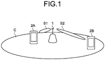
- the overview of the technology of the present disclosure will be described with reference to FIG. 1 .
- FIG. 1 is a diagram for illustrating an overview of a communication system according to an embodiment of the present disclosure.
- the communication system according to the present embodiment includes a base station apparatus 1 and a plurality of terminal devices 2A and 2B.
- the base station apparatus 1 determines a signal waveform to be used for the downlink communication with each of the terminal devices 2, from the plurality of signal waveforms including the single carrier signal. For example, the base station apparatus 1 determines to use either the single carrier signal or a multicarrier signal for the downlink communication.
- the multicarrier signal is, for example, CP-OFDM.
- examples of the single carrier signal include DFT-S-OFDM, SC-QAM, Single carrier with zero padding/unique word, and the like.
- the base station apparatus 1 determines the signal waveform to be used, for each terminal device 2, and notifies the terminal device 2 of information about the determined signal waveform.
- the base station apparatus 1 performs the downlink communication with the terminal device 2 by using the signal waveform that the base station apparatus 1 has notified of.
- the base station apparatus 1 selects the multicarrier signal and performs downlink communication S1 with the terminal device 2A positioned near the center of a cell C. Furthermore, the base station apparatus 1 selects the single carrier signal and performs downlink communication S2 with the terminal device 2B positioned near an edge of the cell C.
- the required transmission power for the terminal device 2A positioned near the center of the cell C is smaller than that for the terminal device 2B positioned near the cell edge, and thus, the transmission power required can be easily secured even if the PAPR is high.
- the base station apparatus 1 selects the multicarrier signal for the terminal device 2A positioned near the center of the cell C, and selects the single carrier signal for the terminal device 2B positioned near the edge of the cell C.
- the base station apparatus 1 allocates the single carrier signal to the downlink communication in which the low PAPR is severely required, and allocates the signal waveform of a signal other than the single carrier signal (here, the multicarrier signal) to the downlink communication in which the low PAPR is not so severely required. Accordingly, the base station apparatus 1 can achieve the low PAPR and the improvement in efficiency of the entire system.
- the method of determining the signal waveform by the base station apparatus 1 is not limited thereto. Details of the method of determining the signal waveform by the base station apparatus 1 will be described later.
- the communication system according to the present embodiment includes the base station apparatus 1 and the terminal devices 2.
- FIG. 2 is a block diagram illustrating a configuration example of the base station apparatus 1 according to an embodiment of the present disclosure.
- the base station apparatus 1 includes an upper layer processing unit 101, a control unit 103, a reception unit 105, a transmission unit 107, and a transmission/reception antenna 109.
- the base station apparatus 1 can be configured to support one or more Radio Access Technologies (RATs).
- RATs Radio Access Technologies
- the base station apparatus 1 is configured to support both LTE and NR.
- some or all of the units included in the base station apparatus 1 can be individually configured according to the RATs.
- the reception unit 105 and the transmission unit 107 are individually configured according to LTE and NR.
- some or all of the units included in the base station apparatus 1 illustrated in FIG. 2 can be individually configured according to a parameter set related to a transmission signal.
- a radio receiver 1057 and a radio transmitter 1077 can be individually configured according to the parameter set related to the transmission signal.
- the upper layer processing unit 101 outputs downlink data (transport block) to the control unit 103.
- the upper layer processing unit 101 performs processing of a Medium Access Control (MAC) layer, a Packet Data Convergence Protocol (PDCP) layer, a radio link control (RLC) layer, and a Radio Resource Control (RRC) layer.
- MAC Medium Access Control
- PDCP Packet Data Convergence Protocol
- RLC radio link control
- RRC Radio Resource Control
- the upper layer processing unit 101 generates control information to control the reception unit 105 and the transmission unit 107, and outputs the control information to the control unit 103.
- the upper layer processing unit 101 performs processing and management related to RAT control, radio resource control, subframe setting, scheduling control, and/or CSI report control.
- the processing and management in the upper layer processing unit 101 are performed for each terminal device or commonly for the terminal devices connected to the base station apparatus.
- the processing and management in the upper layer processing unit 101 may be performed only by the upper layer processing unit 101 or may be acquired from an upper node or another base station apparatus.
- the processing and management in the upper layer processing unit 101 may be individually performed according to the RATs.
- the upper layer processing unit 101 individually performs processing and management according to LTE and processing and management according to NR.
- management related to the RATs is performed.
- management for LTE and/or management for NR is performed.
- the management for NR includes setting and processing of the parameter set related to the transmission signal in the NR cell.
- radio resource control in the upper layer processing unit 101 management of setting information in the base station apparatus is managed.
- radio resource control in the upper layer processing unit 101 generation and/or management of the downlink data (transport block), system information, an RRC message (RRC parameter), and/or MAC Control Element (CE) is performed.
- subframe setting in the upper layer processing unit 101 management of subframe setting, subframe pattern setting, uplink downlink setting, uplink reference UL-DL setting, and/or downlink reference UL-DL setting is performed.
- the subframe setting in the upper layer processing unit 101 is also referred to as base station subframe setting.
- the subframe setting in the upper layer processing unit 101 can be determined on the basis of an uplink traffic and a downlink traffic.
- the subframe setting in the upper layer processing unit 101 can be determined on the basis of a scheduling result of the scheduling control in the upper layer processing unit 101.
- a frequency and subframe to which a physical channel is allocated, a code rate, a modulation method, the transmission power, and the like of the physical channel are determined, on the basis of channel state information received, an estimation value of a propagation channel, channel quality, and the like input from a channel measurement unit 1059.
- the control unit 103 generates the control information (DCI format) on the basis of the scheduling result of the scheduling control in the upper layer processing unit 101.
- the CSI report from each terminal device 2 is controlled. For example, setting related to a CSI reference resource to be assumed for calculation of CSI in the terminal device 2 is controlled.
- the control unit 103 controls the reception unit 105 and the transmission unit 107 on the basis of the control information from the upper layer processing unit 101.
- the control unit 103 generates the control information for the upper layer processing unit 101 and outputs the control information to the upper layer processing unit 101.
- the control unit 103 receives an input of a decoded signal from a decoding unit 1051 and an input of a channel estimation result from the channel measurement unit 1059.
- the control unit 103 outputs a signal to be encoded to an encoding unit 1071. Furthermore, the control unit 103 is used to control the whole or part of the base station apparatus 1.
- control unit 103 determines the signal waveform (hereinafter, also referred to as signal waveform for use) to be used for downlink communication with each terminal device 2, from the single carrier signal and the multicarrier signal.
- the control unit 103 controls the transmission unit 107 to notify the terminal device 2 of information about the signal waveform for use, by using a predetermined signal waveform (e.g., the single carrier signal).
- the control unit 103 controls the transmission unit 107, and performs the downlink communication with the terminal device 2 by using the signal waveform for use that has been notified of. Note that processing performed by the control unit 103 will be described in detail later.
- the reception unit 105 under the control of the control unit 103, receives a signal transmitted from the terminal device 2 via the transmission/reception antenna 109, further performs reception processing such as separation, demodulation, and decoding, and outputs information subjected to the reception processing to the control unit 103.
- reception processing in the reception unit 105 is performed on the basis of setting defined in advance or setting that the terminal device 2 is notified of by the base station apparatus 1.
- the reception unit 105 includes the decoding unit 1051, a demodulation unit 1053, a demultiplexing unit 1055, the radio receiver 1057, and the channel measurement unit 1059.
- the radio receiver 1057 performs, on an uplink signal received via the transmission/reception antenna 109, conversion (down conversion) into an intermediate frequency, removal of an unnecessary frequency component, control of an amplification level to maintain an appropriate signal level, quadrature demodulation based on an in-phase component and a quadrature component of the received signal, conversion from an analog signal into a digital signal, removal of a Guard Interval (GI), and/or extraction of a frequency domain signal by Fast Fourier Transform (FFT).
- GI Guard Interval
- FFT Fast Fourier Transform
- the demultiplexing unit 1055 separates an uplink channel such as PUCCH or PUSCH and/or an uplink reference signal, from a signal input from the radio receiver 1057.
- the demultiplexing unit 1055 outputs the uplink reference signal to the channel measurement unit 1059.
- the demultiplexing unit 1055 performs compensation of the propagation channel for the uplink channel, on the basis of the estimation value of the propagation channel input from the channel measurement unit 1059.
- the demodulation unit 1053 performs, on a modulation symbol from the uplink channel, demodulation of the received signal by using a modulation method such as Binary Phase Shift Keying (BPSK), ⁇ /2BPSK, Quadrature Phase shift Keying (QPSK), Quadrature Amplitude Modulation (16QAM), 64QAM, or 256QAM.
- BPSK Binary Phase Shift Keying
- QPSK Quadrature Phase shift Keying
- 16QAM Quadrature Amplitude Modulation
- 64QAM 64QAM
- 256QAM 256QAM
- the decoding unit 1051 performs decode processing on encoded bits demodulated in the uplink channel. Decoded uplink data and uplink control information are output to the control unit 103. The decoding unit 1051 performs decode processing on PUSCH for each transport block.
- the channel measurement unit 1059 measures the estimation value of the propagation channel and/or the quality of a channel, on the basis of the uplink reference signal input from the demultiplexing unit 1055, and outputs the estimation value and/or the channel quality to the demultiplexing unit 1055 and/or the control unit 103.
- the channel measurement unit 1059 measures the estimation value of the propagation channel for propagation channel compensation on PUCCH or PUSCH by using UL-DMRS, and measures the channel quality in the uplink by using SRS.
- the transmission unit 107 under the control of the control unit 103, performs transmission processing such as encoding, modulation, and multiplexing, on downlink control information and the downlink data that are input from the upper layer processing unit 101. For example, the transmission unit 107 multiplexes generated PHICH, PDCCH, EPDCCH, PDSCH, and downlink reference signal to generate the transmission signal. Note that the transmission processing in the transmission unit 107 is performed, on the basis of the setting defined in advance, the setting that the terminal device 2 is notified of by the base station apparatus 1, or setting notified of through the PDCCH or EPDCCH transmitted in the same subframe.
- the transmission unit 107 includes the encoding unit 1071, a modulation unit 1073, a multiplexing unit 1075, the radio transmitter 1077, and a downlink reference signal generation unit 1079.
- the encoding unit 1071 performs encoding of an HARQ indicator (HARQ-ACK), the downlink control information, and the downlink data that are input from the control unit 103, by using a predetermined encoding method such as block coding, convolutional coding, or turbo coding.
- the modulation unit 1073 modulates encoded bits that are input from the encoding unit 1071 by using a predetermined modulation method such as BPSK, ⁇ /2BPSK, QPSK, 16QAM, 64QAM, or 256QAM.
- the downlink reference signal generation unit 1079 generates the downlink reference signal on the basis of Physical cell identification (PCI), the RRC parameter set in the terminal device 2, and the like.
- PCI Physical cell identification
- the multiplexing unit 1075 multiplexes the modulation symbols and the downlink reference signals in each channel, and arranges the modulation symbols and the downlink reference signals in a predetermined resource element.
- the radio transmitter 1077 performs, on the signal from the multiplexing unit 1075, processing such as conversion into a signal in a time domain by Inverse Fast Fourier Transform (IFFT), addition of the guard interval, generation of a baseband digital signal, conversion into an analog signal, quadrature modulation, conversion from a signal having the intermediate frequency to a signal having a high frequency (up conversion), removal of an unnecessary frequency component, and amplification of power, and generates the transmission signal.
- IFFT Inverse Fast Fourier Transform
- the transmission signal output from the radio transmitter 1077 is transmitted from the transmission/reception antenna 109.
- the radio transmitter 1077 is configured to support a plurality of downlink signal waveforms.
- the radio transmitter 1077 in the base station apparatus 1 that supports both of a first signal waveform (the multicarrier signal) and a second signal waveform (the single carrier signal) will be described in detail with reference to FIGS. 3 to 5 .
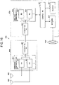
- FIG. 3 is a block diagram illustrating a configuration example of the radio transmitter 1077.
- the radio transmitter 1077 includes a signal waveform switching unit 401, a first signal waveform transmission unit 403, and a second signal waveform transmission unit 405.
- the signal waveform switching unit 401 is configured to switch the signal waveforms in the downlink communication for transmission, between the first signal waveform and the second signal waveform, according to a predetermined condition or situation.
- the downlink communication for transmission uses the first signal waveform
- the downlink communication is subjected to transmission processing by the first signal waveform transmission unit 403.
- the downlink communication is subjected to transmission processing by the second signal waveform transmission unit 405.
- a switching condition and situation in the signal waveform switching unit 401 will be described later.
- the signal waveform switching unit is also referred to as a signal waveform control unit.
- the first signal waveform transmission unit 403 and the second signal waveform transmission unit 405 are illustrated as different processing units, but the first and second signal waveform transmission units 403 and 405 may be configured as one processing unit so that the transmission processing is only partially switched.
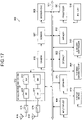
- FIG. 4 is a block diagram illustrating a configuration example of the first signal waveform transmission unit 403.
- the first signal waveform transmission unit 403 transmits a downlink channel and signal to be transmitted by using CP-OFDM, as the signal waveform for uplink communication.
- the first signal waveform transmission unit 403 includes an S/P unit 4031, an Inverse Discrete Fourier Transform (IDFT) unit 4033, a P/S unit 4035, and a CP insertion unit 4037.
- IDFT Inverse Discrete Fourier Transform
- the S/P unit 4031 converts an input serial signal into a parallel signal of size M.
- the size M is determined depending on the size of resource in the frequency domain used for the downlink communication.
- the parallel signal of size M is input to the IDFT unit 4033 so as to correspond to a predetermined frequency domain.
- the IDFT unit 4033 performs inverse Fourier transform processing on a parallel signal of size N.
- IFFT Inverse Fast Fourier Transform
- the P/S unit 4035 converts the parallel signal of size N into a serial signal.
- the CP insertion unit 4037 inserts a predetermined CP for each OFDM symbol.
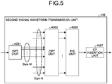
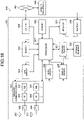
- FIG. 5 is a block diagram illustrating a configuration example of the second signal waveform transmission unit 405.
- the second signal waveform transmission unit 405 transmits the downlink channel and signal to be transmitted by using, for example, SC-FDMA, as the signal waveform for downlink communication.
- the second signal waveform transmission unit 405 includes a DFT unit 4051, an inverse discrete Fourier transform (IDFT) unit 4053, a P/S unit 4055, and a CP insertion unit 4057.
- the DFT unit 4051 performs DFT conversion into a parallel signal of size M.
- the size M is determined depending on the size of resource in the frequency domain used for the downlink communication.
- the parallel signal of size M is input to the IDFT unit 4053 so as to correspond to a predetermined frequency domain.
- the IDFT unit 4053 performs inverse Fourier transform processing on the parallel signal of size N.
- IFFT Inverse Fast Fourier Transform
- the P/S unit 4055 converts the parallel signal of size N into a serial signal.
- the CP insertion unit 4057 inserts a predetermined CP for each SC-FDMA symbol.
- FIG. 6 is a block diagram illustrating a configuration example of each terminal device 2 according to an embodiment of the present disclosure.
- the terminal device 2 includes an upper layer processing unit 201, a control unit 203, a reception unit 205, a transmission unit 207, and a transmission/reception antenna 209.
- the terminal device 2 is configured to support one or more Radio Access Technologies (RATs).
- RATs Radio Access Technologies
- the terminal device 2 is configured to support both LTE and NR.
- some or all of the units included in the terminal device 2 can be individually configured according to the RATs.
- the reception unit 205 and the transmission unit 207 are individually configured according to LTE and NR.
- some or all of the units included in the terminal device 2 illustrated in FIG. 6 can be individually configured according to a parameter set related to a transmission signal.
- a radio receiver 2057 and a radio transmitter 2077 can be individually configured according to the parameter set related to the transmission signal.
- the upper layer processing unit 201 outputs uplink data (transport block) to the control unit 203.
- the upper layer processing unit 201 performs processing of a Medium Access Control (MAC) layer, a Packet Data Convergence Protocol (PDCP) layer, a Radio Link Control (RLC) layer, and a Radio Resource Control (RRC) layer.
- MAC Medium Access Control
- PDCP Packet Data Convergence Protocol
- RLC Radio Link Control
- RRC Radio Resource Control
- the upper layer processing unit 201 generates control information to control the reception unit 205 and the transmission unit 207, and outputs the control information to the control unit 203.
- the upper layer processing unit 201 performs processing and management related to RAT control, radio resource control, subframe setting, scheduling control, and/or CSI report control.
- the processing and management in the upper layer processing unit 201 are performed on the basis of setting defined in advance and/or setting based on the control information set or notified of by the base station apparatus 1.
- the control information from the base station apparatus 1 includes the RRC parameter, the MAC control element, or the DCI.
- the processing and management in the upper layer processing unit 201 may be individually performed according to the RATs.
- the upper layer processing unit 201 individually performs processing and management according to LTE and processing and management according to NR.
- management related to the RAT is performed.
- management for LTE and/or management for NR is performed.
- the management for NR includes setting and processing of the parameter set related to the transmission signal in the NR cell.
- radio resource control in the upper layer processing unit 201 management of setting information in the terminal device is managed.
- radio resource control in the upper layer processing unit 201 generation and/or management of the uplink data (transport block), system information, an RRC message (RRC parameter), and/or MAC Control Element (CE) is performed.
- subframe setting in the upper layer processing unit 201 subframe setting in the base station apparatus 1 and/or a base station apparatus different from the base station apparatus 1 is managed.
- the subframe setting includes uplink or downlink setting for a subframe, subframe pattern setting, uplink downlink setting, uplink reference UL-DL setting, and/or downlink reference UL-DL setting. Note that the subframe setting in the upper layer processing unit 201 is also referred to as terminal subframe setting.
- the control information for control related to scheduling of the reception unit 205 and the transmission unit 207 is generated on the basis of the DCI (scheduling information) from the base station apparatus 1.
- control related to the CSI report to the base station apparatus 1 is performed.
- control related to the CSI report to the base station apparatus 1 is performed.
- setting related to the CSI reference resource to be assumed for calculation of CSI in a channel measurement unit 2059 is controlled.
- a resource (timing) used to report CSI is controlled on the basis of the DCI and/or the RRC parameter.
- the control unit 203 controls the reception unit 205 and the transmission unit 207 on the basis of the control information from the upper layer processing unit 201.
- the control unit 203 generates the control information for the upper layer processing unit 201 and outputs the control information to the upper layer processing unit 201.
- the control unit 203 receives an input of a decoded signal from a decoding unit 2051 and an input of a channel estimation result from the channel measurement unit 2059.
- the control unit 203 outputs a signal to be encoded to an encoding unit 2071.
- the control unit 203 may be used to control the whole or part of the terminal device 2.
- control unit 203 acquires, from the base station apparatus 1 via the reception unit 205, the information about the signal waveform for use that is used for downlink communication with the base station apparatus 1, that is, the single carrier signal or the multicarrier signal.
- the information about the signal waveform for use is information transmitted with a predetermined signal waveform (e.g., the single carrier signal).
- the control unit 203 controls the reception unit 205, and performs the downlink communication with the base station apparatus 1 by using the signal waveform for use.
- the reception unit 205 under the control of the control unit 203, receives a signal transmitted from the base station apparatus 1 via the transmission/reception antenna 209, further performs reception processing such as separation, demodulation, and decoding, and outputs information subjected to the reception processing to the control unit 203.
- reception processing in the reception unit 205 is performed on the basis of setting defined in advance or a notification or setting from the base station apparatus 1.
- the reception unit 205 includes the decoding unit 2051, a demodulation unit 2053, a demultiplexing unit 2055, the radio receiver 2057, and the channel measurement unit 2059.
- the radio receiver 2057 performs, on an uplink signal received via the transmission/reception antenna 209, conversion (down conversion) into an intermediate frequency, removal of an unnecessary frequency component, control of an amplification level to maintain an appropriate signal level, quadrature demodulation based on an in-phase component and a quadrature component of the received signal, conversion from an analog signal into a digital signal, removal of a Guard Interval (GI), and/or extraction of a frequency domain signal by Fast Fourier Transform (FFT).
- conversion down conversion
- removal of an unnecessary frequency component control of an amplification level to maintain an appropriate signal level
- quadrature demodulation based on an in-phase component and a quadrature component of the received signal
- conversion from an analog signal into a digital signal removal of a Guard Interval (GI), and/or extraction of a frequency domain signal by Fast Fourier Transform (FFT).
- GI Guard Interval
- FFT Fast Fourier Transform
- the radio receiver 2057 is configured to support a plurality of uplink signal waveforms.
- the radio receiver 2057 in the terminal device 2 that supports both of the first signal waveform (the multicarrier signal) and the second signal waveform (the single carrier signal) will be described in detail with reference to with reference to FIGS. 7 to 9 .
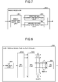
- FIG. 7 is a block diagram illustrating a configuration example of the radio receiver 2057.
- the radio receiver 2057 includes a signal waveform switching unit 301, a first signal waveform reception unit 303, and a second signal waveform reception unit 305.
- the signal waveform switching unit 301 is configured to be switched depending on whether the received downlink communication uses the first signal waveform or the second signal waveform, according to a predetermined condition or situation. In a case where the received downlink communication uses the first signal waveform, the downlink communication is subjected to reception processing by the first signal waveform reception unit 303. In a case where the received downlink communication uses the second signal waveform, the downlink communication is subjected to reception processing by the second signal waveform reception unit 305. A switching condition and situation in the signal waveform switching unit 301 will be described later. Note that the signal waveform switching unit is also referred to as a signal waveform control unit. Furthermore, in FIG. 7 , the first signal waveform reception unit 303 and the second signal waveform reception unit 305 are illustrated as different processing units, but the first and second signal waveform reception units 303 and 305 may be configured as one processing unit so that the reception processing is only partially switched.
- FIG. 8 is a block diagram illustrating a configuration example of the first signal waveform reception unit 303.
- the first signal waveform reception unit 303 performs the reception processing for the downlink channel and signal transmitted by using CP-OFDM, as the signal waveform for downlink communication.
- the first signal waveform reception unit 303 includes a CP removal unit 3031, an S/P unit 3033, a discrete Fourier transform (DFT) unit 3035, and a P/S unit 3037.
- DFT discrete Fourier transform
- the CP removal unit 3031 removes the Cyclic prefix (CP) added in the received downlink communication.
- the S/P unit 3033 converts the input serial signal into the parallel signal of size N.
- the DFT unit 3035 performs Fourier transform processing. Here, in the Fourier transform processing in a case where the size N is a power of 2, Fast Fourier Transform (FFT) processing can be performed.
- the P/S unit 3037 converts the input parallel signal of size M into the serial signal.
- the downlink communication signal transmitted by the terminal device 2 that performs the reception processing is input to the P/S unit 3037.
- the size M is determined depending on the size of resource in the frequency domain used for the downlink communication.
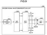
- FIG. 9 is a block diagram illustrating a configuration example of the second signal waveform reception unit 305.
- the second signal waveform reception unit 305 receives the downlink channel and signal transmitted by using, for example, SC-FDMA, as the signal waveform for downlink communication.
- the second signal waveform reception unit 305 includes a CP removal unit 3051, an S/P unit 3053, a discrete Fourier transform (DFT) unit 3055, and an inverse discrete Fourier transform (IDFT) unit 3057.
- DFT discrete Fourier transform
- IDFT inverse discrete Fourier transform
- the CP removal unit 3051 removes the Cyclic prefix (CP) added in the received downlink communication.
- the S/P unit 3053 converts the input serial signal into the parallel signal of size N.
- the DFT unit 3055 performs Fourier transform processing. Here, in the Fourier transform processing in a case where the size N is a power of 2, Fast Fourier Transform (FFT) processing can be performed.
- the IDFT unit 3057 performs inverse Fourier transform processing on the input signal of size M.
- the downlink communication signal transmitted by the terminal device 2 that performs the reception processing is input to the IDFT 3057.
- the size M is determined depending on the size of resource in the frequency domain used for the downlink communication.
- the demultiplexing unit 2055 separates a downlink channel such as PHICH, PDCCH, EPDCCH, or PDSCH, a downlink synchronization signal, and/or the downlink reference signal from the signal input from the radio receiver 2057.
- the demultiplexing unit 2055 outputs the downlink reference signal to the channel measurement unit 2059.
- the demultiplexing unit 2055 performs compensation of the propagation channel for the downlink channel, on the basis of the estimation value of the propagation channel input from the channel measurement unit 2059.
- the demodulation unit 2053 performs, on a modulation symbol from the downlink channel, demodulation of the received signal by using the modulation method such as BPSK, ⁇ /2BPSK, QPSK, 16QAM, 64QAM, or 256QAM.
- the demodulation unit 2053 performs separation and demodulation on a downlink channel multiplexed in MIMO.
- the decoding unit 2051 performs decode processing on encoded bits demodulated in the downlink channel. Decoded downlink data and downlink control information are output to the control unit 203. The decoding unit 2051 performs decode processing on PDSCH for each transport block.
- the channel measurement unit 2059 measures the estimation value of the propagation channel and/or the quality of a channel, on the basis of the downlink reference signal input from the demultiplexing unit 2055, and outputs the estimation value and/or the channel quality to the demultiplexing unit 2055 and/or the control unit 203.
- the downlink reference signal used for the measurement by the channel measurement unit 2059 may be determined on the basis of at least a transmission mode set by the RRC parameter, and/or another RRC parameter.
- DL-DMRS measures the estimation value of the propagation channel for performing propagation channel compensation for PDSCH or EPDCCH.
- CRS measures the estimation value of the propagation channel for performing propagation channel compensation on PDCCH or PDSCH, and/or a channel in the downlink for reporting CSI.
- the CSI-RS measures the channel in the downlink for reporting CSI.
- the channel measurement unit 2059 calculates Reference Signal Received Power (RSRP) and/or Reference Signal Received Quality (RSRQ) on the basis of the CRS, CSI-RS, or a detection signal, and outputs the RSRP and/or RSRQ to the upper layer processing unit 201.
- RSRP Reference Signal Received Power
- RSRQ Reference Signal Received Quality
- the transmission unit 207 under the control of the control unit 203, performs transmission processing such as encoding, modulation, and multiplexing, on uplink control information and the uplink data that are input from the upper layer processing unit 201. For example, the transmission unit 207 generates and multiplexes the uplink channel such as PUSCH or PUCCH, and/or the uplink reference signal, and generates the transmission signal. Note that the transmission processing in the transmission unit 207 is performed on the basis of setting defined in advance or setting or notification from the base station apparatus 1.
- the transmission unit 207 includes the encoding unit 2071, a modulation unit 2073, a multiplexing unit 2075, the radio transmitter 2077, and an uplink reference signal generation unit 2079.
- the encoding unit 2071 performs encoding of an HARQ indicator (HARQ-ACK), the uplink control information, and the uplink data that are input from the control unit 203, by using a predetermined encoding method such as block coding, convolutional coding, or turbo coding.
- the modulation unit 2073 modulates encoded bits that are input from the encoding unit 2071 by using a predetermined modulation method such as BPSK, ⁇ /2BPSK, QPSK, 16QAM, 64QAM, or 256QAM.
- the uplink reference signal generation unit 2079 generates the uplink reference signal on the basis of the RRC parameter or the like set in the terminal device 2.
- the multiplexing unit 2075 multiplexes the modulation symbols and the uplink reference signals in each channel, and arranges the modulation symbols and the downlink reference signals in a predetermined resource element.
- the radio transmitter 2077 performs, on the signal from the multiplexing unit 2075, processing such as conversion into a signal in a time domain by Inverse Fast Fourier Transform (IFFT), addition of the guard interval, generation of a baseband digital signal, conversion into an analog signal, quadrature modulation, conversion from a signal having the intermediate frequency to a signal having a high frequency (up conversion), removal of an unnecessary frequency component, and amplification of power, and generates the transmission signal.
- IFFT Inverse Fast Fourier Transform
- the transmission signal output from the radio transmitter 2077 is transmitted from the transmission/reception antenna 209.
- the communication system according to the present embodiment uses one of the single carrier signal or the multicarrier signal to perform downlink communication between the base station apparatus 1 and each terminal device 2.
- each of the base station apparatus 1 and the terminal device 2 supports one or more Radio Access Technologies (RATs).
- the RATs include LTE and NR.
- One RAT corresponds to one cell (component carrier).
- the RATs correspond to different cells.
- the cell represents a combination of a downlink resource, an uplink resource, and/or sidelink.
- a cell corresponding to LTE is referred to as an LTE cell
- a cell corresponding to NR is referred to an NR cell.
- the base station apparatus 1 and the terminal device 2 are configured to support communication using a set of one or more cells in the downlink, the uplink, and/or the sidelink.
- the set of a plurality of cells is also referred to as carrier aggregation or dual connectivity.
- carrier aggregation and the dual connectivity will be described in detail later.
- each cell uses a predetermined frequency bandwidth. The maximum value, the minimum value, and a possible value in the predetermined frequency bandwidth can be defined in advance.
- FIG. 10 is a diagram illustrating an example of setting of the component carrier according to the embodiment of the present disclosure.
- one LTE cell and two NR cells are set.
- One LTE cell is set as a primary cell.
- the two NR cells are set as a primary secondary cell and a secondary cell.
- the two NR cells are aggregated by carrier aggregation.
- the LTE cell and the NR cells are aggregated by dual connectivity. Note that the LTE cell and the NR cells may be aggregated by carrier aggregation.
- NR can be connected with the assistance of the LTE cell, the primary cell, removing the need for supporting some functions such as functions for stand-alone communication.
- the functions for stand-alone communication include functions necessary for initial connection.
- FIG. 11 is a diagram illustrating an example of setting of the component carrier according to the embodiment of the present disclosure.
- two NR cells are set.
- the two NR cells are set as the primary cell and the secondary cell and are integrated by carrier aggregation.
- the NR cells support the functions for stand-alone communication, removing the need for assistance of the LTE cell.
- the two NR cells may be aggregated by dual connectivity.
- FIG. 12 is an explanatory diagram illustrating an example of the NR frame structure.
- a radio frame of 10 ms includes two half frames.
- a duration of a half frame is 5 ms.
- Each of the half frames includes five subframes.
- one subframe includes one or more slots.
- One slot includes 14 symbols for normal CP and 12 symbols for extended CP.
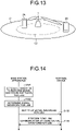
- FIG. 14 is a sequence diagram illustrating an example of the communication process according to the embodiment of the present disclosure.
- the base station apparatus 1 determines first whether to switch the signal waveforms (Step S101). Subsequently, when switching the signal waveforms for downlink communication, the base station apparatus 1 determines the signal waveform for use (Step S102). Note that, when the signal waveforms are not switched, the base station apparatus 1 performs downlink communication by using the signal waveform that is defined in advance.
- the base station apparatus 1 notifies the corresponding terminal device 2 of information about the determined signal waveform for use (waveform information) (Step S103). Then, the base station apparatus 1 and the terminal device 2 perform downlink communication by using the signal waveform for use (Step S104).
- downlink communication is performed by switching the single carrier signal and the multicarrier signal.
- the base station apparatus 1 selects one of the single carrier signal and the multicarrier signal.
- the base station apparatus 1 determines whether to perform a signal waveform switching process, as illustrated in Step S101 of FIG. 14 .
- the base station apparatus 1 determines whether to switch the signal waveforms according to, for example, the capability of the base station apparatus 1.
- the base station apparatus 1 determines whether to switch the signal waveforms according to, for example, the maximum transmission power of the base station apparatus 1 or the presence or absence of a transmission circuit corresponding to the plurality of signal waveforms. For example, in a case where the maximum transmission power of the base station apparatus 1 is equal to or larger than a predetermined threshold and the power amplifier can be operated in a linear region even if the multicarrier signal is transmitted, the base station apparatus 1 performs downlink communication by using the multicarrier signal without switching the signal waveforms.
- the base station apparatus 1 performs downlink communication by using the multicarrier signal without switching the signal waveforms.
- the base station apparatus 1 may determine whether to switch the signal waveforms according to coverage or data throughput required for the downlink communication. For example, in a case where the required coverage is narrow, having small transmission power, the base station apparatus 1 selects the multicarrier signal that has high frequency utilization efficiency without switching the signal waveforms. In addition, also in a case where the required data throughput is high, the base station apparatus 1 selects the multicarrier signal that has high frequency utilization efficiency without switching the signal waveforms.
- the base station apparatus 1 determines whether to switch the signal waveforms, for example, according to the capability of the terminal device 2 that is a communication partner. In this case, the base station apparatus 1 determines whether to switch the signal waveforms, for the plurality of terminal devices 2. The base station apparatus 1 determines whether to switch the signal waveforms according to, for example, whether the terminal device 2 has a reception circuit corresponding to the plurality of signal waveforms. For example, in a case where, the terminal device 2 has a reception circuit corresponding to a single signal waveform, for example, in a case where the terminal device 2 has a reception circuit corresponding only to the multicarrier signal, the base station apparatus 1 performs downlink communication with the multicarrier signal without switching the signal waveforms.
- the base station apparatus 1 determines to perform the switching process, the base station apparatus 1 switches the signal waveforms according to, for example, the physical channel or the frequency band.
- the base station apparatus 1 switches the signal waveforms, for a predetermined physical channel or a predetermined frequency band.
- targets for which the base station apparatus 1 is to switch the signal waveforms will be described.
- the base station apparatus 1 switches, for example, the signal waveforms, for a predetermined physical channel/signal.
- the base station apparatus 1 uses, for example, the signal waveform selected from the multicarrier signal and the single carrier signal, for a physical channel/signal used for transmission of data information, more specifically, PDSCH and/or PDSCH DMRS.
- a predetermined signal waveform is used, for a physical channel/signal other than a predetermined physical channel, for example, a physical channel/signal used for transmission of the control information, more specifically, SSB, PDCCH, and/or CSI-RS.
- the base station apparatus 1 can use the single carrier signal as the predetermined signal waveform to widen the coverage, more reliably transmitting the control information.
- the signal waveforms are switched for a predetermined BWP.
- the base station apparatus 1 switches the signal waveforms in another BWP excepting initial active bandwidth, but transmits a signal by using the predetermined signal waveform in initial active bandwidth.
- the base station apparatus 1 uses, for example, initial active bandwidth to notify of information about the signal waveform to be used in the another BWP.
- the base station apparatus 1 switches the signal waveforms, for a predetermined cell. For example, the base station apparatus 1 performs transmission by switching signal waveforms, in a secondary cell (Scell) or a secondary cell group (SCG) including the secondary cell.
- the base station apparatus 1 transmits a signal by using a predetermined signal waveform. In this case, the base station apparatus 1 notifies of the information about the signal waveform to be used in the Scell or the SCG by using, for example, the Pcell or the MCG.
- selection criteria for selecting the signal waveform for use will be described, which is used when the base station apparatus 1 selects the signal waveform to be used for downlink communication in Step S102 of FIG. 14 .
- the base station apparatus 1 switches the signal waveforms according to the following selection criteria.
- the base station apparatus 1 selects the signal waveform for use, according to the position of the terminal device 2. For example, when the distance between the base station apparatus 1 and the terminal device 2 are distant from each other, large transmission power is required. Low PAPR is demanded to ensure large transmission power by the power amplifier. Therefore, the base station apparatus 1 selects the single carrier signal as the signal waveform for use, when the large transmission power is required. On the other hand, when the base station apparatus 1 and the terminal device are closer to each other, the transmission power may be small. Therefore, PAPR may be high, and in this case, the base station apparatus 1 selects the multicarrier signal as the signal waveform for use.
- FIG. 13 is a diagram illustrating a positional relationship between the base station apparatus 1 and terminal devices 2.
- the base station apparatus 1 selects the single carrier signal as the signal waveform to be used for downlink communication with the terminal device 2B positioned at the cell edge C1.
- the base station apparatus 1 selects the multicarrier signal as the signal waveform for use that is used for downlink communication with the terminal device 2A positioned at the cell center C2.
- the base station apparatus 1 determines whether the terminal device 2 is positioned at the cell edge C1 or at the cell center C2, on the basis of, for example, RSRP. More specifically, when the terminal device 2 has an RSRP less than a predetermined threshold, the base station apparatus 1 determines that the terminal device 2 is spaced apart and the terminal device 2 is positioned at the cell edge C1. On the other hand, when the RSRP of the terminal device 2 is equal to or larger than the predetermined threshold, it is determined that the distance to the terminal device 2 is positioned closer and the terminal device 2 is positioned at the cell center C2.
- the base station apparatus 1 may determine the position of the terminal device 2 in the cell C, on the basis of the position information of the terminal device 2. For example, the base station apparatus 1 determines whether the terminal device 2 is positioned at the cell edge C1 or at the cell center C2, on the basis of the position information acquired from GPS or the like mounted on the terminal device 2.
- the base station apparatus 1 may select the signal waveform according to the bandwidth or the channel width that is used for downlink communication. For example, the wider the band, the lower transmit power density. Therefore, in a case where the single carrier signal with which the transmission power can be increased is selected, the transmit power density can be ensured even with a wider band. On the other hand, in a case where the multicarrier signal with high PAPR that makes it difficult to increase the transmission power is selected, the transmission power density decreases as the band becomes wider, and the multicarrier signal is desirably used in a narrow band to ensure the transmission power.
- the base station apparatus 1 selects the signal waveform according to the bandwidth or the channel width used for downlink communication. Specifically, the base station apparatus 1 selects the single carrier signal when the bandwidth is equal to or larger than a predetermined width, and selects the multicarrier signal when the bandwidth is less than the predetermined width.
- the base station apparatus 1 may select the signal waveform according to a time length. For example, the base station apparatus 1 selects the single carrier signal, for a predetermined time length, and selects the multicarrier signal, for the other time lengths. In this manner, the base station apparatus 1 can switch the signal waveforms according to the time length.
- the base station apparatus 1 switches the signal waveforms, for example, for each slot. For example, the base station apparatus 1 selects the single carrier signal, for a predetermined slot, and selects the multicarrier signal, for the other slots.
- the time length (e.g., the number of slots) for which the single carrier signal is selected may be the same as or different from the time length (e.g., the number of slots) for which the multicarrier signal is selected.
- the time length of the downlink communication with the multicarrier signal may be longer or may be shorter than that the time length of the downlink communication with the single carrier signal.
- the multicarrier signal and the single carrier signal may be switched at the same periodic intervals.
- the base station apparatus 1 selects the signal waveform for use, according to a signal waveform for use in uplink communication.
- a signal waveform for use in uplink communication In the uplink communication, either a single carrier signal or a multicarrier signal is used.
- the base station apparatus 1 uses the signal waveforms to be used for the uplink communication also in the downlink communication.
- This configuration makes it possible, for example, to use the same signal waveform between uplink communication and downlink communication, and the signal waveform for use, for both of the uplink communication and the downlink communication can be notified of at a time. Note that the notification of the information about the signal waveform for use, by the base station apparatus 1 will be described later in detail.
- the base station apparatus 1 selects the signal waveform for use, according to a signal waveform for use of another wireless communication system.
- a frequency band of 60 GHz is used not only for cellular communication but also for wireless communication (e.g., IEEE 802.11ad, 11ay, and the like) according to, for example, a wireless LAN standard.
- the base station apparatus 1 selects the signal waveforms used by the another wireless communication system, as the signal waveforms for use.
- the single carrier signal is used The base station apparatus 1 that has detected the communication using the single carrier signal selects the single carrier signal as the signal waveform for use.
- performing communication using the same signal waveform as that of another wireless communication system makes it possible for the another wireless communication system to readily detect the signal transmitted by the base station apparatus 1.
- the base station apparatus 1 can also more easily detect the signal transmitted and received to and from the another wireless communication system.
- the base station apparatus 1 switches the signal waveforms in any of three frequency modes, that is, static mode, semi-static mode, and dynamic mode.
- the base station apparatus 1 selects a signal waveform for use once, notifies the terminal device 2 of the selected signal waveform, and then uses the signal waveform notified of. In this case, the base station apparatus 1 adds the information about the selected signal waveform for use, for example, to system information and notifies the terminal device 2 of the information.
- the base station apparatus 1 selects a signal waveform for use at predetermined periodic interval, and notifies the terminal device 2 of the selected signal waveform. In this case, the base station apparatus 1 adds the information about the selected signal waveform for use, for example, to RRC signaling and notifies the terminal device 2 of the information.
- the base station apparatus 1 selects a signal waveform for use every time transmitting the data information, and notifies the terminal device 2 of the selected signal waveform. In this case, the base station apparatus 1 adds the information about the selected signal waveform for use, for example, to the PDCCH and notifies the terminal device 2 of the information.
- the base station apparatus 1 that has switched the signal waveforms for use notifies the terminal device 2 of the selected signal waveform for use.
- a method of transmitting the information about the signal waveform for use to the terminal device 2 by the base station apparatus 1 three methods are considered, that is, an Explicit transmission method, an Implicit transmission method, and a method of blind detection of the signal waveform for use that is used on the terminal device 2 side.
- the base station apparatus 1 transmits the waveform information, the waveform information being added to, for example, the system information, RRC signaling, or DCI.
- the system information is classified into a Master Information Block (MIB) and a System Information Block (SIB) .
- MIB Master Information Block
- SIB System Information Block
- the base station apparatus 1 adds the waveform information to, for example, MIB as the system information, and transmits the waveform information.
- the waveform information is added to the MIB as, for example, one bit parameter.
- the waveform information sets, for example, 1 or 0 to the one bit parameter to specify a signal waveform of the single carrier signal or the multicarrier signal.
- the waveform information is added to, for example, the Synchronization signal (SSB/PBCH block) of MIB and transmitted.
- the base station apparatus 1 transmits the SSB by using the predetermined signal waveform (e.g., the single carrier signal), and transmits a physical downlink channel/signal other than the SSB by using the signal waveform specified in the waveform information.
- the base station apparatus 1 transmits PDCCH or PDSCH included in SIB, by using a signal waveform specified in the waveform information.
- the base station apparatus 1 may add the waveform information to, for example, SIB as the system information, and transmits the waveform information.
- the base station apparatus 1 transmits SSB, type0-PDCCH, and PDSCH scheduled by type0-PDCCH, by using the predetermined signal waveform (e.g., the single carrier signal), and transmits the other physical downlink channels/signals by using the signal waveform specified in the waveform information.
- the predetermined signal waveform e.g., the single carrier signal
- transmitting a predetermined physical downlink channel/signal by using the predetermined signal waveform makes it possible for the terminal device 2 to more reliably receive the predetermined physical downlink channel/signal.
- the base station apparatus 1 adds a parameter indicating the waveform information to, for example, the RRC signaling after RRC connection, and transmits the parameter. Therefore, the base station apparatus 1 can periodically notify of the waveform information.
- the base station apparatus 1 adds the waveform information to DCI of PDCCH and transmits the waveform information.
- the base station apparatus 1 notifies of the waveform information by using field included in DCI.
- the base station apparatus 1 is allowed to dynamically switch the signal waveforms.
- the base station apparatus 1 may notify of the waveform information in association with notification of the signal waveform for use for the uplink communication.
- the base station apparatus 1 gives notification that the signal waveform for use for uplink communication is the signal waveform for use for downlink communication. In other words, the base station apparatus 1 collectively notifies of the information about the signal waveforms for use for uplink communication and downlink communication, as one piece of information.
- notification of the waveform information added to, for example, DCI is transmitted, for example, with the single carrier signal, thus, complicating multiplexing of resources of the single carrier signal and the multicarrier signal. Therefore, it is desirable to transmit the notification of the waveform information as early as possible, for example, using the system information such as MIB.
- notification of the waveform information by using the system information makes it difficult to dynamically allocate the signal waveform.
- the base station apparatus 1 adds the waveform information to the system information such as MIB and transmits the system information and then switches the signal waveform for use
- the waveform information after switching may be added to the RRC signaling or DCI, for transmission.
- the base station apparatus 1 transmits the waveform information a plurality of times, thus enabling to individually switch the signal waveforms for use used by the terminal devices 2 while transmitting the waveform information common to the cells.
- the base station apparatus 1 changes, for example, the configuration of SSB, the configuration of PDCCH, or the like according to the signal waveform for use to notify each terminal device 2 of the waveform information.
- the base station apparatus 1 transmits SSB having a configuration corresponding to a selected signal waveform for use to notify the terminal device 2 of the waveform information.
- a Primary Synchronization Signal (PSS) and/or Secondary Synchronization Signal (SSS) sequence is defined for each signal waveform, and the base station apparatus 1 transmits PSS and/or SSS according to the defined sequence.
- PSS and/or the SSS is detected, the terminal device 2 determines a signal waveform corresponding to the detected PSS and/or SSS as the signal waveform for use.
- the base station apparatus 1 is configured to notify of the waveform information by associating the signal waveform with the PSS and/or SSS sequence.
- the base station apparatus 1 may notify of the waveform information by resource allocation of PSS/SSS/PBCH (SSB block).
- PSS/SSS/PBCH resources for PSS/SSS/PBCH (SSB block) are defined for each signal waveform.
- the terminal device 2 determines, as the signal waveform for use, the signal waveform corresponding to resources to which the detected PSS/SSS/PBCH (SSB block) is transmitted In this manner, the association between the signal waveform with the resources makes it possible for the base station apparatus 1 to notify of the waveform information.
- associating the signal waveform with CORESET or search space for PDCCH, the type of DCI, RNTI, and the like makes it possible for the base station apparatus 1 to notify the terminal device 2 of the waveform information by transmitting PDCCH.
- the signal waveform is associated with CORESET, for example, each of CORESET #0 and the other CORESETs, and when the base station apparatus 1 transmits either CORESET #0 or the other CORESETs, the terminal device 2 detects the signal waveform for use.
- the signal waveform is associated with each of Common Search Space (CSS) and UE-specific Search Space (USS) of the search space, and the base station apparatus 1 notifies the terminal device 2 of the signal waveform for use, depending on whether the PDCCH is transmitted in which search section.
- CSS Common Search Space
- USS UE-specific Search Space
- the signal waveform may be associated with the type of DCI, for example, each of fallback DCI and non-fallback DCI.
- the terminal device 2 detects the signal waveform for use.
- the signal waveform may be associated with RNTI, for example, each of C-RNTI and other RNTIs.
- the terminal device 2 detects the signal waveform for use.
- a method of acquiring (blind detection) the waveform information can be provided.
- the signal transmitted by the base station apparatus 1 by using the signal waveform for use is detected by the terminal device 2.
- the single carrier signal has a low PAPR
- the multicarrier signal has a high PAPR. Therefore, for example, the terminal device 2 detects an amplitude variation of the received signal to determine whether the signal waveform of the received signal shows the single carrier signal or the multicarrier signal.
- the terminal device 2 blindly detects the state of the signal waveform of a symbol in downlink communication. More specifically, the terminal device 2 detects a variation (e.g., PAPR) in amplitude on the frequency axis. When the detected variation is below a predetermined threshold, the terminal device 2 determines that the signal waveform for use is the single carrier signal, and when the detected variation is equal to or more than the predetermined threshold, the terminal device 2 determines that the signal waveform for use is the multicarrier signal.
- a variation e.g., PAPR
- the terminal device 2 can detect the signal waveform for use, even if the base station apparatus 1 does not notify of the waveform information.
- the change of the frame structure by using the single carrier signal and the multicarrier signal by the base station apparatus 1 may cause the terminal device 2 to blindly detect the signal waveform.
- the base station apparatus 1 changes a frame format or a symbol length of the radio frame, a CP configuration, or the like of the radio frame, for each signal waveform.
- the base station apparatus 1 changes the CP configuration with the single carrier signal and the multicarrier signal. More specifically, the base station apparatus 1 changes the CP configuration, for example, to zero padding or unique word, according to the signal waveform. Assuming that the CP configuration is zero padding, the power of a portion corresponding to the CP of the radio frame becomes zero. On the other hand, assuming that the CP configuration is a unique word, the power of a portion corresponding to the CP of the radio frame does not become zero. Therefore, the terminal device 2 detects the signal waveform of the received signal by performing threshold determination on the power of the portion of the received signal corresponding to the CP.
- the base station apparatus 1 can also add the waveform information to the transmission signal and transmit the transmission signal to the terminal device 2 by using the signal waveform for use.
- the base station apparatus 1 adds the waveform information to the CP, for transmission. Therefore, even if the base station apparatus 1 does not separately transmit the waveform information, the base station apparatus 1 and the terminal device 2 can perform communication using the signal waveform for use.
- the base station apparatus 1 may change the symbol length according to, for example, the signal waveform for use.
- one slot includes 14 symbols, but the number of symbols of one slot may be changed, for example, according to the signal waveform. More specifically, for example, the base station apparatus 1 sets the number of symbols in one slot to 14, when communication is performed by using the multicarrier signal, and sets the number of symbols in one slot to 28 that is twice the number of symbols of that in the communication using the multicarrier signal, when communication is performed by using the single carrier signal.
- the base station apparatus 1 may change the number of symbols of CP instead of that of slot, according to the signal waveform.
- the base station apparatus 1 continuously transmits a plurality of CPs when the single carrier signal is used, and transmits one CP when the multicarrier signal is used.
- the base station apparatus 1 may change the number of CPs, that is, the CP length according to the signal waveform.
- the base station apparatus 1 Upon notifying of the information about the signal waveform for use by the method described above, the base station apparatus 1 uses the signal waveform for use to perform downlink communication with the terminal device 2, as illustrated in Step S104 of FIG. 14 .
- Step S104 of FIG. 14 a communication process performed by the base station apparatus 1, according to the signal waveform for use will be described.
- the base station apparatus 1 changes a resource allocation method according to the signal waveform for use. For example, in a case where communication is performed using the multicarrier signal, the base station apparatus 1 discontinuously allocates the transmission signal to the resources. In addition, when the single carrier signal is used, the base station apparatus 1 continuously allocates the transmission signal to the resources.
- the base station apparatus 1 selects the single carrier signal when it is desired to transmit a signal with low PAPR.
- the single carrier signals can be transmitted with low PAPR by being arranged together on a frequency axis. Therefore, when selecting the single carrier signal, the base station apparatus 1 selects non-contiguous allocation (Resource allocation Type 1) as the resource allocation method.
- the base station apparatus 1 selects non-contiguous allocation (resource allocation type 0). Therefore, the base station apparatus 1 can transmit a signal by using a portion having good characteristics on the frequency axis, improving the frequency utilization efficiency.
- the base station apparatus 1 determines the number of layers (the number of data signals multiplexed) according to the signal waveform. For example, in a case where the single carrier signal is used, the number of layers is limited to two or less of a vertically polarized wave and a horizontally polarized wave. On the other hand, in a case where the multicarrier signal is used, the number of layers is not particularly limited. Therefore, the base station apparatus 1 may transmit the multicarrier signal by setting the number of layers, for example, to three or more.
- the base station apparatus 1 sets the number of layers in MIMO to two or less in a case where the single carrier signal is used, and sets the number of layers to three or more in a case where the multicarrier signal is used. In this manner, the base station apparatus 1 determines the number of layers in MIMO, according to the signal waveform.
- precoding and feedback e.g., Channel State Information (CSI)
- CSI Channel State Information
- RI Rank Indicator
- PMI Precoding Matrix Indicator
- the base station apparatus 1 determines a modulation method according to the signal waveform. For example, in a case where low PAPR is demanded, the base station apparatus 1 performs downlink communication using the single carrier signal. Therefore, when the single carrier signal is used, the base station apparatus 1 selects a modulation method with low PAPR.
- An example of the modulation method with low PAPR includes ⁇ /2BPSK.
- the base station apparatus 1 uses the multicarrier signal to perform to perform downlink communication. Therefore, when the multicarrier signal is used, the base station apparatus 1 selects a modulation method other than the modulation method with low PAPR. For example, the base station apparatus 1 selects a modulation method such as QPSK or 16QAM that has higher transmission efficiency than BPSK, as the modulation method for the multicarrier signal.
- a modulation method such as QPSK or 16QAM that has higher transmission efficiency than BPSK
- determination of the modulation method according to the signal waveform by the base station apparatus 1 improves the transmission efficiency while satisfying the request for low PAPR.
- the base station apparatus 1 determines the signal waveform for use that is used for downlink communication, from the plurality of signal waveforms including the single carrier signal.
- the base station apparatus 1 notifies the terminal device 2 of the information about the determined signal waveform for use (waveform information).
- the terminal device 2 that has received the notification performs downlink communication with the base station apparatus 1 by using the signal waveform for use.
- Selection of the single carrier signal by the base station apparatus 1 makes it possible to satisfy the request for low PAPR, and selection of a signal waveform other than the single carrier signal by the base station apparatus 1 makes it possible to improve the transmission efficiency of the entire system.
- the base station apparatus 1 may be implemented as any type of evolved Node B (eNB) such as macro eNB or small eNB.
- the small eNB may be eNB that covers a cell smaller than a macro cell, such as pico eNB, micro eNB, or home (femto) eNB.
- the base station apparatus 1 may be implemented as another type of base station such as NodeB or Base Transceiver Station (BTS).
- BTS Base Transceiver Station
- the base station apparatus 1 may include a main body (also referred to as base station apparatus) that controls wireless communication, and one or more Remote Radio Heads (RRHs) that are arranged at places different from that of the main body.
- RRHs Remote Radio Heads
- various types of terminals which are described later, may operate as the base station apparatus 1 by temporarily or semi-persistently serving base station functions.
- the terminal device 2 may be implemented as a mobile terminal such as a smartphone, tablet Personal Computer (PC), notebook PC, portable game terminal, a portable/dongle mobile router, and digital camera, and an in-vehicle terminal such as a car navigation device.
- the terminal device 2 may be implemented as a terminal (also referred to as Machine Type Communication (MTC) terminal) that performs machine to machine (M2M) communication.
- the terminal device 2 may be a wireless communication module (e.g., an integrated circuit module including one die) that is mounted on each of these terminals.
- FIG. 15 is a block diagram illustrating a first example of a schematic configuration of eNB to which a technology according to the present disclosure is applicable.
- the eNB 800 includes one or more antennas 810 and a base station apparatus 820. Each of the antennas 810 and the base station apparatus 820 may be connected to each other via an RF cable.
- Each of the antennas 810 includes a single or a plurality of antenna elements (e.g., a plurality of antenna elements constituting a MIMO antenna), and is used for transmission and reception of a radio signal from and to the base station apparatus 820.
- the eNB 800 may include a plurality of the antennas 810 that correspond to, for example, a plurality of frequency bands used by the eNB 800. Note that although FIG. 15 illustrates an example in which the eNB 800 includes the plurality of the antennas 810, the eNB 800 may include a single antenna 810.
- the base station apparatus 820 includes a controller 821, a memory 822, a network interface 823, and a wireless communication interface 825.
- the controller 821 may be, for example, CPU or DSP, and causes various functions of an upper layer of the base station apparatus 820 to be performed. For example, the controller 821 generates a data packet from data in a signal processed by the wireless communication interface 825, and transfers the generated packet via the network interface 823. The controller 821 may generate a bundled packet by bundling data from a plurality of baseband processors and transfer the generated bundled packet. In addition, the controller 821 may have a logical function of executing control, such as Radio Resource Control, Radio Bearer Control, Mobility Management, Admission Control, or Scheduling. Furthermore, the control may be executed in cooperation with peripheral eNB or a core network node.
- the memory 822 includes RAM and ROM, and stores programs executed by the controller 821 and various control data (e.g., terminal list, transmission power data, scheduling data, etc.).
- the network interface 823 is a communication interface for connecting the base station apparatus 820 to a core network 824.
- the controller 821 may communicate with a core network node or another eNB via the network interface 823.
- the eNB 800 and the core network node or the another eNB may be connected to each other by a logical interface (e.g., S1 interface or X2 interface).
- the network interface 823 may be a wired communication interface or a wireless communication interface for wireless backhaul.
- the network interface 823 may use, for wireless communication, a frequency band higher than a frequency band used by the wireless communication interface 825.
- the wireless communication interface 825 supports any cellular communication system such as Long Term Evolution (LTE) or LTE-Advanced, and provides a wireless connection to a terminal positioned in a cell of the eNB 800 via each antenna 810.
- the wireless communication interface 825 can typically include a baseband (BB) processor 826, an RF circuit 827, and the like.
- the BB processor 826 may perform, for example, encoding/decoding, modulation/demodulation, and multiplexing/demultiplexing, and executes various signal processing in each layer (e.g., L1, Medium Access Control (MAC), Radio Link Control (RLC), and Packet Data Convergence Protocol (PDCP)).
- L1 Medium Access Control
- RLC Radio Link Control
- PDCP Packet Data Convergence Protocol
- the BB processor 826 may have some or all of the logical functions described above.
- the BB processor 826 may include a module including a memory that stores a communication control program, a processor that executes the program, and a related circuit, and the BB processor 826 may have a function that is changeable by updating the program.
- the module described above may be a card or a blade inserted into a slot of the base station apparatus 820, or may be a chip mounted on the card or the blade.
- the RF circuit 827 may include a mixer, a filter, an amplifier, and the like, and transmits and receives a radio signal via the antenna 810.
- the wireless communication interface 825 includes a plurality of BB processors 826 as illustrated in FIG. 15 , and the plurality of BB processors 826 may correspond to, for example, a plurality of frequency bands used by the eNB 800. Furthermore, the wireless communication interface 825 includes a plurality of RF circuits 827 as illustrated in FIG. 15 , and the plurality of RF circuits 827 may correspond to, for example, a plurality of antenna elements. Note that although the example in which the wireless communication interface 825 includes the plurality of BB processors 826 and the plurality of RF circuits 827 is illustrated in FIG. 15 , the wireless communication interface 825 may include a single BB processor 826 or a single RF circuit 827.
- FIG. 16 is a block diagram illustrating a second example of a schematic configuration of eNB to which a technology according to the present disclosure is applicable.
- the eNB 830 includes one or more antennas 840, a base station apparatus 850, and RRH 860. Each of the antennas 840 and the RRH 860 can be connected to each other via an RF cable. In addition, the base station apparatus 850 and the RRH 860 can be connected to each other via a high-speed line such as an optical fiber cable.
- Each of the antennas 840 includes a single or a plurality of antenna elements (e.g., a plurality of antenna elements constituting a MIMO antenna), and is used for transmission and reception of a radio signal from and to the RRH 860.
- the eNB 830 may include a plurality of the antennas 840 that correspond to, for example, a plurality of frequency bands used by the eNB 830. Note that although FIG. 16 illustrates an example in which the eNB 830 includes the plurality of the antennas 840, the eNB 830 may include a single antenna 840.
- the base station apparatus 850 includes a controller 851, a memory 852, a network interface 853, a wireless communication interface 855, and a connection interface 857.
- the controller 851, the memory 852, and the network interface 853 are configured similarly to the controller 821, the memory 822, and the network interface 823 which are described with reference to FIG. 15 .
- the wireless communication interface 855 supports any cellular communication system such as LTE or LTE-Advanced, and provides a wireless connection to a terminal positioned in a sector corresponding to the RRH 860 via the RRH 860 and each antenna 840.
- the wireless communication interface 855 can typically include a BB processor 856, and the like.
- the BB processor 856 is configured similarly to the BB processor 826 which is described with reference to FIG. 15 , except that the BB processor 856 is connected to an RF circuit 864 of the RRH 860 via the connection interface 857.
- the wireless communication interface 855 includes a plurality of BB processors 856 as illustrated in FIG.
- the wireless communication interface 855 may correspond to, for example, a plurality of frequency bands used by the eNB 830. Note that although the example in which the wireless communication interface 855 includes the plurality of BB processors 856 is illustrated in FIG. 16 , the wireless communication interface 855 may include a single BB processor 856.
- connection interface 857 is an interface for connecting the base station apparatus 850 (wireless communication interface 855) to the RRH 860.
- the connection interface 857 may be a communication module for communication on the high-speed line connecting the base station apparatus 850 (wireless communication interface 855) and the RRH 860.
- the RRH 860 includes a connection interface 861 and a wireless communication interface 863.
- connection interface 861 is an interface for connecting the RRH 860 (wireless communication interface 863) to the base station apparatus 850.
- the connection interface 861 may be a communication module for communication on the high-speed line.
- the wireless communication interface 863 transmits and receives a radio signal via each antenna 840.
- the wireless communication interface 863 may typically include the RF circuit 864, and the like.
- the RF circuit 864 may include a mixer, a filter, an amplifier, and the like, and transmits and receives a radio signal via the antenna 840.
- the wireless communication interface 863 includes a plurality of RF circuits 864 as illustrated in FIG. 16 , and the plurality of RF circuits 864 may correspond to, for example, a plurality of antenna elements. Note that although the example in which the wireless communication interface 863 includes the plurality of RF circuits 864 is illustrated in FIG. 16 , the wireless communication interface 863 may include a single RF circuit 864.
- the eNB 800, the eNB 830, the base station apparatus 820, or the base station apparatus 850 illustrated in FIGS. 15 and 16 can correspond to the base station apparatus 1 described with reference to FIG. 2 and the like.
- FIG. 17 is a block diagram illustrating an example of a schematic configuration of a smartphone 900 to which a technology according to the present disclosure is applicable.
- the smartphone 900 includes a processor 901, a memory 902, a storage 903, an external connection interface 904, a camera 906, a sensor 907, a microphone 908, an input device 909, a display device 910, a speaker 911, a wireless communication interface 912, one or more antenna switches 915, one or more antennas 916, a bus 917, a battery 918, and an auxiliary controller 919.
- the processor 901 may be, for example, CPU or System on Chip (SoC), and controls functions of an application layer and the other layers of the smartphone 900.
- the memory 902 includes RAM and ROM, and stores programs and data executed by the processor 901.
- the storage 903 can include a storage medium such as a semiconductor memory or a hard disk.
- the external connection interface 904 is an interface for connecting an external device such as a memory card or a Universal Serial Bus (USB) device, to the smartphone 900.
- USB Universal Serial Bus
- the camera 906 includes, for example, an imaging element such as a Charge Coupled Device (CCD) or a Complementary Metal Oxide Semiconductor (CMOS) to generate a captured image.
- the sensor 907 can include, for example, a sensor group of a positioning sensor, gyroscope sensor, geomagnetic sensor, acceleration sensor, and the like.
- the microphone 908 converts voice input to the smartphone 900 into a voice signal.
- the input device 909 includes, for example, a touch sensor that detects a touch on a screen of the display device 910, a keypad, a keyboard, a button, or a switch, and receives an operation or information input from the user.
- the display device 910 includes the screen such as a liquid crystal display (LCD) or an organic light emitting diode (OLED) display, and displays an output image of the smartphone 900.
- the speaker 911 converts a voice signal output from the smartphone 900 into voice.
- the wireless communication interface 912 supports any cellular communication system such as LTE or LTE-Advanced, and performs wireless communication.
- the wireless communication interface 912 may typically include a BB processor 913, an RF circuit 914, and the like.
- the BB processor 913 may perform, for example, encoding/decoding, modulation/demodulation, and multiplexing/demultiplexing, and executes various signal processing for wireless communication.
- the RF circuit 914 may include a mixer, a filter, an amplifier, and the like, and transmits and receives a radio signal via the antenna 916.
- the wireless communication interface 912 may be a one-chip module on which the BB processor 913 and the RF circuit 914 are integrated.
- the wireless communication interface 912 may include a plurality of the BB processors 913 and a plurality of the RF circuits 914 as illustrated in FIG. 17 . Note that although the example in which the wireless communication interface 912 includes the plurality of BB processors 913 and the plurality of RF circuits 914 is illustrated in FIG. 17 , the wireless communication interface 912 may include a single BB processor 913 or a single RF circuit 914.
- the wireless communication interface 912 may support another type of wireless communication system such as a near field wireless communication system, a proximity wireless communication system, or a wireless Local Area Network (LAN) system, and may include the BB processor 913 and the RF circuit 914 for each wireless communication system, in such a configuration.
- the antenna switches 915 are configured to switch the connection destinations of the antennas 916, between a plurality of circuits (e.g., circuits for different wireless communication systems) included in the wireless communication interface 912.
- Each of the antennas 916 includes a single or a plurality of antenna elements (e.g., a plurality of antenna elements constituting a MIMO antenna), and is used for transmission and reception of a radio signal from and to the wireless communication interface 912.
- the smartphone 900 may have a plurality of antennas 916 as illustrated in FIG. 17 . Note that although FIG. 17 illustrates an example in which the smartphone 900 includes the plurality of the antennas 916, the smartphone 900 may include a single antenna 916.
- the smartphone 900 may include the antenna 916 for each wireless communication system.
- the antenna switches 915 may be omitted from the configuration of the smartphone 900.
- the bus 917 connects the processor 901, the memory 902, the storage 903, the external connection interface 904, the camera 906, the sensor 907, the microphone 908, the input device 909, the display device 910, the speaker 911, the wireless communication interface 912, and the auxiliary controller 919 to each other.
- the battery 918 supplies power to the respective blocks of the smartphone 900 illustrated in FIG. 17 via feed lines partially indicated by a broken line in the drawing.
- the auxiliary controller 919 causes minimum necessary functions of the smartphone 900 to be performed, for example, in a sleep mode.
- FIG. 18 is a block diagram illustrating an example of a schematic configuration of a car navigation device 920 to which a technology according to the present disclosure is applicable.
- the car navigation device 920 includes a processor 921, a memory 922, a global positioning system (GPS) module 924, a sensor 925, a data interface 926, a content player 927, a storage medium interface 928, an input device 929, a display device 930, a speaker 931, a wireless communication interface 933, one or more antenna switches 936, one or more antennas 937, and a battery 938.
- GPS global positioning system
- the processor 921 may be, for example, CPU or SoC, and controls a navigation function and the other functions of the car navigation device 920.
- the memory 922 includes RAM and ROM, and stores programs and data executed by the processor 921.
- the GPS module 924 uses a GPS signal received from a GPS satellite to measure a position (e.g. latitude, longitude, and altitude) of the car navigation device 920.
- the sensor 925 can include, for example, a sensor group of a gyroscope sensor, geomagnetic sensor, pressure sensor, and the like.
- the data interface 926 is connected to an in-vehicle network 941 via, for example, a terminal which is not illustrated and acquires data, such as vehicle speed data, generated on the vehicle side.
- the content player 927 reproduces content stored in a storage medium (e.g., CD or DVD) inserted into the storage medium interface 928.
- the input device 929 includes, for example, a touch sensor that detects a touch on a screen of the display device 930, a button, or a switch, and receives an operation or information input from the user.
- the display device 930 has a screen such as an LCD or OLED display, and displays a navigation function or an image of content to be played back.
- the speaker 931 outputs sound of the navigation function or the content played back.
- the wireless communication interface 933 supports any cellular communication system such as LTE or LTE-Advanced, and performs wireless communication.
- the wireless communication interface 933 may typically include a BB processor 934, an RF circuit 935, and the like.
- the BB processor 934 may perform, for example, encoding/decoding, modulation/demodulation, and multiplexing/demultiplexing, and executes various signal processing for wireless communication.
- the RF circuit 935 may include a mixer, a filter, an amplifier, and the like, and transmits and receives a radio signal via the antenna 937.
- the wireless communication interface 933 may be a one-chip module on which the BB processor 934 and the RF circuit 935 are integrated.
- the wireless communication interface 933 may include a plurality of the BB processors 934 and a plurality of the RF circuits 935 as illustrated in FIG. 18 . Note that although the example in which the wireless communication interface 933 includes the plurality of BB processors 934 and the plurality of RF circuits 935 is illustrated in FIG. 18 , the wireless communication interface 933 may include a single BB processor 934 or a single RF circuit 935.
- the wireless communication interface 933 may support another type of wireless communication system such as a near field wireless communication system, a proximity wireless communication system, or a wireless Local Area Network (LAN) system, and may include the BB processor 934 and the RF circuit 935 for each wireless communication system, in such a configuration.
- the antenna switches 936 are configured to switch the connection destinations of the antennas 937, between a plurality of circuits (e.g., circuits for different wireless communication systems) included in the wireless communication interface 933.
- Each of the antennas 937 includes a single or a plurality of antenna elements (e.g., a plurality of antenna elements constituting a MIMO antenna), and is used for transmission and reception of a radio signal from and to the wireless communication interface 933.
- the car navigation device 920 may have a plurality of antennas 937 as illustrated in FIG. 18 . Note that although FIG. 18 illustrates an example in which the car navigation device 920 includes the plurality of the antennas 937, the car navigation device 920 may include a single antenna 937.
- the car navigation device 920 may include the antenna 937 for each wireless communication system.
- the antenna switches 936 may be omitted from the configuration of the car navigation device 920.
- the battery 938 supplies power to the respective blocks of the car navigation device 920 illustrated in FIG. 18 via feed lines partially indicated by a broken line in the drawing. In addition, the battery 938 accumulates power supplied from the vehicle side.
- the technology according to the present disclosure may be implemented as an in-vehicle system (or vehicle) 940 that includes one or more blocks of the car navigation device 920 described above, and further includes the in-vehicle network 941 and a vehicle-side module 942.
- the vehicle-side module 942 generates vehicle-side data such as a vehicle speed, an engine speed, or failure information, and outputs the generated data to the in-vehicle network 941.
- the signal waveforms used for downlink communication may be switched in communication other than the cellular communication, as well.
- the satellite station may switch the signal waveforms.
- the satellite communication unlike the cellular communication described above, communication is performed using microwaves instead of the millimeter waves.
- a high-performance power amplifier cannot be mounted in the satellite station, in some cases.
- a signal waveform having low PAPR may be required in order to operate the power amplifier with a high output to send a signal to the ground station. Therefore, also in satellite communication, switching the signal waveforms using the technology of the present disclosure makes it possible to further improve the transmission efficiency while satisfying low PAPR.
- the component elements of the devices are illustrated as functional concepts and are not necessarily required to be physically configured as illustrated.
- specific forms of distribution or integration of the devices are not limited to those illustrated, and all or some of the specific forms may be configured by being functionally or physically distributed or integrated in appropriate units, according to various loads or usage conditions.
- a microscope has been described as an example of the image processing apparatus, but the image processing of the present disclosure is also applicable to an image capturing device other than the microscope.
- the present technology may also be configured as below.
Landscapes
- Engineering & Computer Science (AREA)
- Signal Processing (AREA)
- Computer Networks & Wireless Communication (AREA)
- Physics & Mathematics (AREA)
- Discrete Mathematics (AREA)
- General Physics & Mathematics (AREA)
- Mathematical Physics (AREA)
- Mobile Radio Communication Systems (AREA)
Applications Claiming Priority (2)
| Application Number | Priority Date | Filing Date | Title |
|---|---|---|---|
| JP2019217326 | 2019-11-29 | ||
| PCT/JP2020/043587 WO2021106837A1 (fr) | 2019-11-29 | 2020-11-24 | Dispositif terminal, dispositif de station de base et procédé de communication |
Publications (2)
| Publication Number | Publication Date |
|---|---|
| EP4068885A1 true EP4068885A1 (fr) | 2022-10-05 |
| EP4068885A4 EP4068885A4 (fr) | 2022-12-21 |
Family
ID=76130471
Family Applications (1)
| Application Number | Title | Priority Date | Filing Date |
|---|---|---|---|
| EP20893805.0A Pending EP4068885A4 (fr) | 2019-11-29 | 2020-11-24 | Dispositif terminal, dispositif de station de base et procédé de communication |
Country Status (5)
| Country | Link |
|---|---|
| US (1) | US20220400470A1 (fr) |
| EP (1) | EP4068885A4 (fr) |
| KR (1) | KR20220108042A (fr) |
| CN (1) | CN114731667A (fr) |
| WO (1) | WO2021106837A1 (fr) |
Families Citing this family (4)
| Publication number | Priority date | Publication date | Assignee | Title |
|---|---|---|---|---|
| WO2022190379A1 (fr) * | 2021-03-12 | 2022-09-15 | 株式会社Nttドコモ | Terminal et procédé de communication |
| WO2023095708A1 (fr) * | 2021-11-26 | 2023-06-01 | ソニーグループ株式会社 | Dispositif de station de base, dispositif de communication radio et système de communication radio |
| CN116489792A (zh) * | 2022-01-12 | 2023-07-25 | 维沃移动通信有限公司 | 下行传输方法、终端及网络侧设备 |
| US11632271B1 (en) * | 2022-02-24 | 2023-04-18 | T-Mobile Usa, Inc. | Location-based channel estimation in wireless communication systems |
Family Cites Families (6)
| Publication number | Priority date | Publication date | Assignee | Title |
|---|---|---|---|---|
| CN101965692B (zh) * | 2009-04-24 | 2014-06-04 | 联发科技股份有限公司 | 载波分配方法、基站和移动站 |
| US11405914B2 (en) * | 2016-09-26 | 2022-08-02 | Qualcomm Incorporated | Waveform selection in wireless communications |
| US11012280B2 (en) * | 2017-02-03 | 2021-05-18 | Ntt Docomo, Inc. | User terminal and radio communication method |
| US10667244B2 (en) * | 2017-03-23 | 2020-05-26 | Qualcomm Incorporated | Techniques and apparatuses for waveform signaling for downlink communications |
| US10644827B2 (en) * | 2017-04-06 | 2020-05-05 | Qualcomm Incorporated | Systems and methods for dynamic switching between waveforms on downlink |
| CN109151981B (zh) * | 2017-06-16 | 2020-10-23 | 华为技术有限公司 | 一种上行波形指示方法及相关设备 |
-
2020
- 2020-11-24 WO PCT/JP2020/043587 patent/WO2021106837A1/fr unknown
- 2020-11-24 US US17/770,057 patent/US20220400470A1/en active Pending
- 2020-11-24 KR KR1020227015776A patent/KR20220108042A/ko unknown
- 2020-11-24 CN CN202080081028.6A patent/CN114731667A/zh active Pending
- 2020-11-24 EP EP20893805.0A patent/EP4068885A4/fr active Pending
Non-Patent Citations (1)
| Title |
|---|
| "3rd GeneRATion Partnership Project; Technical Specification Group Radio Access Network; Study oNRequirements for NR beyond 52.6 GHz (Release 16)", 3GPP TR 38.807, June 2019 (2019-06-01) |
Also Published As
| Publication number | Publication date |
|---|---|
| CN114731667A (zh) | 2022-07-08 |
| US20220400470A1 (en) | 2022-12-15 |
| KR20220108042A (ko) | 2022-08-02 |
| WO2021106837A1 (fr) | 2021-06-03 |
| EP4068885A4 (fr) | 2022-12-21 |
Similar Documents
| Publication | Publication Date | Title |
|---|---|---|
| US10306589B2 (en) | Hybrid reference signals for wireless communication | |
| EP4068885A1 (fr) | Dispositif terminal, dispositif de station de base et procédé de communication | |
| EP3500013B1 (fr) | Dispositif de communication, procédé de communication, et programme pour double connectivité | |
| EP3927040A1 (fr) | Dispositif de communication et procédé de communication | |
| US20230023099A1 (en) | Electronic device, radio communication method, and computer readable storage medium | |
| EP3641170A1 (fr) | Dispositif de communication, procédé de communication, et programme informatique | |
| EP3499832A1 (fr) | Dispositif terminal, dispositif station de base, et procédé de communication | |
| EP3352493B1 (fr) | Dispositif dans un système de communication sans fil et procédé | |
| EP3499972A1 (fr) | Dispositif de communication, procédé de communication, et programme | |
| US10681623B2 (en) | Methods and apparatus for cell access via anchor carrier | |
| US11849443B2 (en) | Electronic device, radio communication method, and computer readable storage medium | |
| EP3972366A2 (fr) | Dispositif de station de base, dispositif terminal, procédé et support d'enregistrement | |
| US20220094501A1 (en) | Terminal device, base station device, method, and recording medium | |
| US11516790B2 (en) | Wireless communication apparatus and wireless communication method | |
| US11375496B2 (en) | Wireless communication device and wireless communication method | |
| US11343038B2 (en) | Electronic device, wireless communication method and computer readable medium | |
| WO2016063599A1 (fr) | Dispositif de terminal, circuit intégré et procédé de communication | |
| US20210099986A1 (en) | Electronic apparatus and method for wireless communication and computer-readable storage medium | |
| EP3664532A1 (fr) | Dispositif de communication et procédé de communication | |
| EP3413668B1 (fr) | Appareil de communication sans fil, procédé de communication, programme d'ordinateur, et système de communication sans fil |
Legal Events
| Date | Code | Title | Description |
|---|---|---|---|
| STAA | Information on the status of an ep patent application or granted ep patent |
Free format text: STATUS: THE INTERNATIONAL PUBLICATION HAS BEEN MADE |
|
| PUAI | Public reference made under article 153(3) epc to a published international application that has entered the european phase |
Free format text: ORIGINAL CODE: 0009012 |
|
| STAA | Information on the status of an ep patent application or granted ep patent |
Free format text: STATUS: REQUEST FOR EXAMINATION WAS MADE |
|
| 17P | Request for examination filed |
Effective date: 20220523 |
|
| AK | Designated contracting states |
Kind code of ref document: A1 Designated state(s): AL AT BE BG CH CY CZ DE DK EE ES FI FR GB GR HR HU IE IS IT LI LT LU LV MC MK MT NL NO PL PT RO RS SE SI SK SM TR |
|
| A4 | Supplementary search report drawn up and despatched |
Effective date: 20221118 |
|
| RIC1 | Information provided on ipc code assigned before grant |
Ipc: H04W 72/12 20090101ALI20221114BHEP Ipc: H04L 27/00 20060101ALI20221114BHEP Ipc: H04L 5/00 20060101ALI20221114BHEP Ipc: H04L 27/26 20060101ALI20221114BHEP Ipc: H04W 72/04 20090101AFI20221114BHEP |
|
| DAV | Request for validation of the european patent (deleted) | ||
| DAX | Request for extension of the european patent (deleted) |