EP4068725A1 - Load balancing method and related device - Google Patents
Load balancing method and related device Download PDFInfo
- Publication number
- EP4068725A1 EP4068725A1 EP20901734.2A EP20901734A EP4068725A1 EP 4068725 A1 EP4068725 A1 EP 4068725A1 EP 20901734 A EP20901734 A EP 20901734A EP 4068725 A1 EP4068725 A1 EP 4068725A1
- Authority
- EP
- European Patent Office
- Prior art keywords
- node
- pod
- weight
- pods
- target
- Prior art date
- Legal status (The legal status is an assumption and is not a legal conclusion. Google has not performed a legal analysis and makes no representation as to the accuracy of the status listed.)
- Granted
Links
- 238000000034 method Methods 0.000 title claims abstract description 74
- 230000008569 process Effects 0.000 claims abstract description 38
- 238000004590 computer program Methods 0.000 claims description 17
- 238000004891 communication Methods 0.000 claims description 10
- 238000004422 calculation algorithm Methods 0.000 description 36
- 238000007726 management method Methods 0.000 description 18
- 101100495256 Caenorhabditis elegans mat-3 gene Proteins 0.000 description 14
- 101100491335 Caenorhabditis elegans mat-2 gene Proteins 0.000 description 12
- 238000010586 diagram Methods 0.000 description 10
- 101100327310 Caenorhabditis elegans emb-27 gene Proteins 0.000 description 9
- 101100438971 Caenorhabditis elegans mat-1 gene Proteins 0.000 description 9
- 241001522296 Erithacus rubecula Species 0.000 description 6
- 230000009467 reduction Effects 0.000 description 5
- 102100033121 Transcription factor 21 Human genes 0.000 description 4
- 101710119687 Transcription factor 21 Proteins 0.000 description 4
- 238000012545 processing Methods 0.000 description 4
- 230000003068 static effect Effects 0.000 description 3
- 238000013461 design Methods 0.000 description 1
- 230000000694 effects Effects 0.000 description 1
- 238000005516 engineering process Methods 0.000 description 1
- 230000006870 function Effects 0.000 description 1
- 230000006872 improvement Effects 0.000 description 1
- 238000012423 maintenance Methods 0.000 description 1
- 230000007246 mechanism Effects 0.000 description 1
- 230000003287 optical effect Effects 0.000 description 1
- 238000012549 training Methods 0.000 description 1
Images


Classifications
-
- G—PHYSICS
- G06—COMPUTING; CALCULATING OR COUNTING
- G06F—ELECTRIC DIGITAL DATA PROCESSING
- G06F9/00—Arrangements for program control, e.g. control units
- G06F9/06—Arrangements for program control, e.g. control units using stored programs, i.e. using an internal store of processing equipment to receive or retain programs
- G06F9/46—Multiprogramming arrangements
- G06F9/50—Allocation of resources, e.g. of the central processing unit [CPU]
- G06F9/5083—Techniques for rebalancing the load in a distributed system
-
- H—ELECTRICITY
- H04—ELECTRIC COMMUNICATION TECHNIQUE
- H04L—TRANSMISSION OF DIGITAL INFORMATION, e.g. TELEGRAPHIC COMMUNICATION
- H04L41/00—Arrangements for maintenance, administration or management of data switching networks, e.g. of packet switching networks
- H04L41/12—Discovery or management of network topologies
- H04L41/122—Discovery or management of network topologies of virtualised topologies, e.g. software-defined networks [SDN] or network function virtualisation [NFV]
-
- G—PHYSICS
- G06—COMPUTING; CALCULATING OR COUNTING
- G06F—ELECTRIC DIGITAL DATA PROCESSING
- G06F9/00—Arrangements for program control, e.g. control units
- G06F9/06—Arrangements for program control, e.g. control units using stored programs, i.e. using an internal store of processing equipment to receive or retain programs
- G06F9/46—Multiprogramming arrangements
- G06F9/50—Allocation of resources, e.g. of the central processing unit [CPU]
- G06F9/5005—Allocation of resources, e.g. of the central processing unit [CPU] to service a request
- G06F9/5027—Allocation of resources, e.g. of the central processing unit [CPU] to service a request the resource being a machine, e.g. CPUs, Servers, Terminals
- G06F9/5038—Allocation of resources, e.g. of the central processing unit [CPU] to service a request the resource being a machine, e.g. CPUs, Servers, Terminals considering the execution order of a plurality of tasks, e.g. taking priority or time dependency constraints into consideration
-
- G—PHYSICS
- G06—COMPUTING; CALCULATING OR COUNTING
- G06F—ELECTRIC DIGITAL DATA PROCESSING
- G06F9/00—Arrangements for program control, e.g. control units
- G06F9/06—Arrangements for program control, e.g. control units using stored programs, i.e. using an internal store of processing equipment to receive or retain programs
- G06F9/46—Multiprogramming arrangements
- G06F9/50—Allocation of resources, e.g. of the central processing unit [CPU]
- G06F9/5005—Allocation of resources, e.g. of the central processing unit [CPU] to service a request
- G06F9/5027—Allocation of resources, e.g. of the central processing unit [CPU] to service a request the resource being a machine, e.g. CPUs, Servers, Terminals
- G06F9/505—Allocation of resources, e.g. of the central processing unit [CPU] to service a request the resource being a machine, e.g. CPUs, Servers, Terminals considering the load
-
- G—PHYSICS
- G06—COMPUTING; CALCULATING OR COUNTING
- G06F—ELECTRIC DIGITAL DATA PROCESSING
- G06F9/00—Arrangements for program control, e.g. control units
- G06F9/06—Arrangements for program control, e.g. control units using stored programs, i.e. using an internal store of processing equipment to receive or retain programs
- G06F9/46—Multiprogramming arrangements
- G06F9/50—Allocation of resources, e.g. of the central processing unit [CPU]
- G06F9/5061—Partitioning or combining of resources
- G06F9/5077—Logical partitioning of resources; Management or configuration of virtualized resources
-
- H—ELECTRICITY
- H04—ELECTRIC COMMUNICATION TECHNIQUE
- H04L—TRANSMISSION OF DIGITAL INFORMATION, e.g. TELEGRAPHIC COMMUNICATION
- H04L41/00—Arrangements for maintenance, administration or management of data switching networks, e.g. of packet switching networks
- H04L41/12—Discovery or management of network topologies
-
- H—ELECTRICITY
- H04—ELECTRIC COMMUNICATION TECHNIQUE
- H04L—TRANSMISSION OF DIGITAL INFORMATION, e.g. TELEGRAPHIC COMMUNICATION
- H04L67/00—Network arrangements or protocols for supporting network services or applications
- H04L67/01—Protocols
- H04L67/10—Protocols in which an application is distributed across nodes in the network
- H04L67/1001—Protocols in which an application is distributed across nodes in the network for accessing one among a plurality of replicated servers
- H04L67/1004—Server selection for load balancing
- H04L67/1008—Server selection for load balancing based on parameters of servers, e.g. available memory or workload
-
- H—ELECTRICITY
- H04—ELECTRIC COMMUNICATION TECHNIQUE
- H04L—TRANSMISSION OF DIGITAL INFORMATION, e.g. TELEGRAPHIC COMMUNICATION
- H04L67/00—Network arrangements or protocols for supporting network services or applications
- H04L67/01—Protocols
- H04L67/10—Protocols in which an application is distributed across nodes in the network
- H04L67/1001—Protocols in which an application is distributed across nodes in the network for accessing one among a plurality of replicated servers
- H04L67/1004—Server selection for load balancing
- H04L67/101—Server selection for load balancing based on network conditions
-
- H—ELECTRICITY
- H04—ELECTRIC COMMUNICATION TECHNIQUE
- H04L—TRANSMISSION OF DIGITAL INFORMATION, e.g. TELEGRAPHIC COMMUNICATION
- H04L67/00—Network arrangements or protocols for supporting network services or applications
- H04L67/01—Protocols
- H04L67/10—Protocols in which an application is distributed across nodes in the network
- H04L67/1001—Protocols in which an application is distributed across nodes in the network for accessing one among a plurality of replicated servers
- H04L67/1004—Server selection for load balancing
- H04L67/1023—Server selection for load balancing based on a hash applied to IP addresses or costs
-
- G—PHYSICS
- G06—COMPUTING; CALCULATING OR COUNTING
- G06F—ELECTRIC DIGITAL DATA PROCESSING
- G06F2209/00—Indexing scheme relating to G06F9/00
- G06F2209/50—Indexing scheme relating to G06F9/50
- G06F2209/505—Clust
-
- H—ELECTRICITY
- H04—ELECTRIC COMMUNICATION TECHNIQUE
- H04L—TRANSMISSION OF DIGITAL INFORMATION, e.g. TELEGRAPHIC COMMUNICATION
- H04L67/00—Network arrangements or protocols for supporting network services or applications
- H04L67/34—Network arrangements or protocols for supporting network services or applications involving the movement of software or configuration parameters
Definitions
- This application relates to the field of computer technologies, and in particular, to a load balancing method and a related device.
- Load balancing refers to allocating task requests to a plurality of nodes (node) in a load balancing cluster according to a scheduling algorithm, to improve a task processing capability of the load balancing cluster.
- load balancing in a container orchestration and management platform for example, Kubernetes
- the manner of allocating the task requests according to the existing scheduling algorithm by using the distributed software is prone to cause additional network overheads. Therefore, how to reduce network overheads when a task request is allocated is a technical problem being studied by a person skilled in the art.
- This application discloses a load balancing method and a related device, so that network overheads can be reduced when a task request is allocated.
- a first aspect of this application discloses a load balancing method, including:
- the weight of each pod is determined based on the topology information of each pod, so that a location relationship of each pod is quantized. Therefore, a value of the weight of a pod can reflect a quantity of layers of switches between a node in which the pod is located and the first node. Then a target pod spaced from the first node by a small quantity of layers of switches may be selected based on a value of the weight of each pod, to process the currently to-be-processed task in the first node, so that a pod spaced from the first node by a large quantity of layers of switches is prevented from being selected to process the currently to-be-processed task in the first node, thereby reducing network overheads.
- the determining topology information of each of a plurality of smallest management units pods in a load balancing cluster to which a first node belongs includes: receiving the topology information of each of the plurality of pods that is sent by a control node.
- the first node directly receives the topology information of each of the plurality of pods that is sent by the control node, without collecting LLDP information of another computing node. This is quicker and reduces time for selecting the target pod.
- the determining topology information of each of a plurality of smallest management units pods in a load balancing cluster to which a first node belongs includes:
- the first node needs to communicate with the at least two nodes, collect the LLDP information of the at least two nodes, and generate the topology information of each of the plurality of pods based on LLDP information collected in real time.
- the manner of generating the topology information is more accurate.
- a pod with a smallest weight may be selected from the plurality of pods as the target pod. Because a quantity of layers of switches between the pod with the smallest weight and the first node is the smallest, the target pod selected in this manner can reduce network overheads in the case of same load.
- the target pod may be selected from the plurality of pods based on load of each of the plurality of pods and the weight of each pod.
- the manner of selecting the target pod by comprehensively considering the value of the weight of each pod and the load of each pod can balance load balancing and network overhead reduction, to improve overall performance of the load balancing cluster.
- the method further includes: directing the currently to-be-processed task in the first node to the target pod, to indicate the target pod to process the currently to-be-processed task.
- this application provides a load balancing apparatus, including:
- the weight of each pod is determined based on the topology information of each pod, so that a location relationship of each pod is quantized. Therefore, a value of the weight can reflect a quantity of layers of switches between a node in which each pod is located and the first node. Then a target pod spaced from the first node by a small quantity of layers of switches may be selected based on a value of the weight of each pod, to process the currently to-be-processed task in the first node, so that additional network overhead caused by selecting a pod spaced from the first node by a large quantity of layers of switches to process the currently to-be-processed task in the first node is avoided.
- the first determining unit is configured to receive the topology information of each of the plurality of pods that is sent by a control node.
- the first node directly receives the topology information of each of the plurality of pods that is sent by the control node, without collecting LLDP information of another computing node. This is quicker and reduces time for selecting the target pod.
- the first determining unit is configured to: collect Link Layer Discovery Protocol LLDP information of the at least two nodes; and generate the topology information of each of the plurality of pods based on the LLDP information of the at least two nodes.
- the first node needs to communicate with the at least two nodes, collect the LLDP information of the at least two nodes, and generate the topology information of each of the plurality of pods based on LLDP information collected in real time.
- the manner of generating the topology information is more accurate.
- the selection unit is configured to: when all of the plurality of pods have same load, select a pod with a smallest weight from the plurality of pods as the target pod. Because a quantity of layers of switches between the pod with the smallest weight and the first node is the smallest, the target pod selected in this manner can reduce network overheads in the case of same load.
- the selection unit is configured to: when the plurality of pods have different load, select the target pod from the plurality of pods based on load of each of the plurality of pods and the weight of each pod.
- the manner of selecting the target pod by comprehensively considering the value of the weight of each pod and the load of each pod can balance load balancing and network overhead reduction, to improve overall performance of the load balancing cluster.
- the apparatus further includes: a directing unit, configured to: after the selection unit selects the target pod from the plurality of pods based on the weight of each pod, direct the currently to-be-processed task in the first node to the target pod, to indicate the target pod to process the currently to-be-processed task.
- a directing unit configured to: after the selection unit selects the target pod from the plurality of pods based on the weight of each pod, direct the currently to-be-processed task in the first node to the target pod, to indicate the target pod to process the currently to-be-processed task.
- this application provides a first node.
- the first node includes a processor, a memory, and a communications interface, the memory is configured to store a computer program, and the processor invokes the computer program to perform the following operations:
- the weight of each pod is determined based on the topology information of each pod, so that a location relationship of each pod is quantized. Therefore, a value of the weight can reflect a quantity of layers of switches between a node in which each pod is located and the first node. Then a target pod spaced from the first node by a small quantity of layers of switches may be selected based on a value of the weight of each pod, to process the currently to-be-processed task in the first node, so that additional network overhead caused by selecting a pod spaced from the first node by a large quantity of layers of switches to process the currently to-be-processed task in the first node is avoided.
- the processor when determining the topology information of each of the plurality of smallest management units pods in the load balancing cluster to which the first node belongs, is configured to: receive, by using the communications interface, the topology information of each of the plurality of pods that is sent by a control node.
- the first node directly receives the topology information of each of the plurality of pods that is sent by the control node, without collecting LLDP information of another computing node. This is quicker and reduces time for selecting the target pod.
- the processor when determining the topology information of each of the plurality of smallest management units pods in the load balancing cluster to which the first node belongs, the processor is configured to:
- the first node needs to communicate with the at least two nodes, collect the LLDP information of the at least two nodes, and generate the topology information of each of the plurality of pods based on LLDP information collected in real time.
- the manner of generating the topology information is more accurate.
- the processor when selecting the target pod from the plurality of pods based on the weight of each pod, the processor is configured to:
- the processor is further configured to: after selecting the target pod from the plurality of pods based on the weight of each pod, direct the currently to-be-processed task in the first node to the target pod, to indicate the target pod to process the currently to-be-processed task.
- the load balancing cluster includes the control node and at least two computing nodes, the first node is one of the at least two computing nodes, the control node is configured to manage the at least two computing nodes, and the plurality of pods are distributed on the at least two computing nodes.
- this application provides a computer-readable storage medium.
- the computer-readable storage medium stores a computer program, and when being executed by a processor, the computer program enables the processor to implement the method described in any one of the first aspect and the optional solutions of the first aspect.
- the weight of each pod is determined based on the topology information of each pod, so that a location relationship of each pod is quantized. Therefore, a value of the weight can reflect a quantity of layers of switches between a node in which each pod is located and the first node. Then a target pod spaced from the first node by a small quantity of layers of switches may be selected based on a value of the weight of each pod, to process the currently to-be-processed task in the first node, so that additional network overhead caused by selecting a pod spaced from the first node by a large quantity of layers of switches to process the currently to-be-processed task in the first node is avoided.
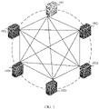
- FIG. 1 is a schematic diagram of an architecture of a load balancing cluster according to an embodiment of this application.
- the load balancing cluster may include one control node 101 and at least two computing nodes 102 (102a to 102e are shown in the figure). Each of the control node 101 and the at least two computing nodes 102 may be one server or one virtual machine on a cloud platform.
- the control node 101 is configured to manage the at least two computing nodes 102.
- the at least two computing nodes 102 are load balancing nodes, and are configured to select a pod from the computing nodes to process a to-be-processed task.
- the to-be-processed task may be a request of opening video software or a request of accessing a website.
- Each computing node may include one or more smallest management units pods.
- the load balancing cluster may be a container orchestration and management platform (for example, Kubernetes, k8s) cluster or a cluster in another running environment.
- Kubernetes is an open source platform for scheduling containers across host clusters.
- Kubernetes can enable a containerized application to be deployed simply and efficiently, and provides a mechanism for application deployment, planning, updating, and maintenance.
- an application is installed by using a plug-in or a script.
- a disadvantage of this is that running, configuration, management, and a lifecycle of the application are bound to a current operating system. This is not conducive to an operation such as upgrading and updating/rollback of the application.
- some functions may be implemented by creating a virtual machine.
- the virtual machine is quite heavy, and is not conducive to portability.
- the containers are deployed by using Kubernetes, the containers are isolated from each other, the containers have respective file systems, processes between the containers do not affect each other, and computing resources can be distinguished.
- the container can be quickly deployed. Because the container is decoupled from an underlying facility and a machine file system, the container can be migrated between operating systems of different clouds and versions.
- a pod is a smallest management unit in a Kubernetes cluster, is a smallest component created or deployed by a user, and is also a resource object used when a containerized application runs on the Kubernetes cluster.
- a unique IP address is assigned to each pod, each pod includes one or more containers, and containers in a same pod are allocated to a same node.
- Containers inside the pod share network space of the pod, including an IP address and a port. The containers inside the pod can communicate with each other by using a host machine of the pod. When the container inside the pod communicates with the outside, a network resource allocated to the pod needs to be used.
- the containers inside the pod can access a shared volume (volume).
- volume may also be used to persist a storage resource in the pod to prevent file loss after the container is restarted.
- the containers inside the pod are always scheduled at the same time and have a common running environment.
- a server selects a target pod in the load balancing cluster by using a load balancing scheduling algorithm, and the target pod serves the client.
- the load balancing scheduling algorithm includes a static scheduling algorithm and a dynamic scheduling algorithm. The following briefly describes the static scheduling algorithm and the dynamic scheduling algorithm
- Static scheduling algorithm A service request is allocated according to a specified algorithm regardless of a quantity of real-time connections.
- a round robin (round robin, RR) algorithm is used to sequentially allocate external requests to nodes in the cluster in turn.
- the nodes are equally treated regardless of actual quantities of connections and load on the nodes.
- weighted round robin weighted round robin, WRR
- WRR weighted round robin
- a destination hashing (destination hashing, DH) algorithm is used to find a corresponding node from a statically allocated hash table by using a destination IP address of a request as a hash key (hash key). If the node is available and is not overloaded, the request is sent to the node; otherwise, null is returned. Requests from a same IP address are redirected to a same node to ensure that a destination address remains unchanged.
- a source hashing (source hashing, SH) algorithm is used to find a corresponding node from a statically allocated hash table by using a source IP address of a request as a hash key (hash key). If the node is available and is not overloaded, the request is sent to the node; otherwise, null is returned.
- SH source hashing
- Dynamic scheduling algorithm A manner of next scheduling is re-determined by checking an activity status of a current quantity of connections on a node.
- a least connection (least connection, LC) algorithm is used, in other words, a next connection request is directed to a node with a small quantity of connections.
- a weighted least connection (weight least-connection, WLC) algorithm is used, in other words, one weight is allocated to each node based on least connections.
- the algorithm is a relatively ideal algorithm.
- a shortest expected delay (shortest expected delay, SED) algorithm is used, in other words, a quantity of inactive connections is no longer considered.
- a never queue (never queue, NQ) algorithm is used.
- the never queue algorithm is an improvement of the SED algorithm.
- allocation of the new request depends not only on a value obtained by the SED algorithm, but also on whether an active connection exists on a node.
- a locality-based least connection (locality-based least-connection, LBLC) algorithm is used, in other words, a quantity of active connections on a node is further considered based on the DH algorithm
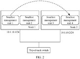
- FIG. 2 is a schematic diagram of a process of allocating a task request.
- a smallest management unit pod 1 in a node 1 is a client (client) that initiates a request.
- the node 1 and a node 2 are connected to a same top-of-rack switch.
- the node 1 allocates the task request to a pod 4 in the node 2, and the pod 4 actually provides a service.
- the task request is not allocated to a pod 2 in the node 1, causing additional network overheads.
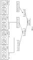
- FIG. 3 shows a load balancing method according to an embodiment of this application.
- the method may be implemented based on the load balancing cluster shown in FIG. 1 .
- the method includes but is not limited to the following steps.
- Step S301 A first node determines topology information of each of a plurality of smallest management units pods in a load balancing cluster to which the first node belongs.
- the first node is a node, for example, a computing node, in the load balancing cluster.
- the plurality of pods are distributed on at least two nodes in the load balancing cluster. For example, some are distributed on the first node, some are distributed on a node connected to a same top-of-rack switch as the first node, some are distributed on a node connected to a same leaf switch as the first node, and some are distributed on a node connected to a same spine switch as the first node.
- a quantity of pods distributed on each of the at least two nodes is not limited herein.
- the plurality of pods can process a currently to-be-processed task in the first node.
- the topology information of each pod represents a node in which the pod is located and a connection relationship between the node in which the pod is located and another node.
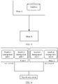
- a node 1 includes a pod 1 and a pod 2
- a node 2 includes a pod 3 and a pod 4
- a node 3 includes a pod 5 and a pod 6
- a node 4 includes a pod 7 and a pod 8
- the node 1 is the first node
- the pod 1 in the node 1 is a client (client) that initiates a request
- both the pod 3 and the pod 4 in the node 2 can provide services for the request
- both the pod 5 and the pod 6 in the node 3 can provide services for the request
- both the pod 7 and the pod 8 in the node 4 can also provide services for the request.
- the node 1 determines, based on an Internet Protocol IP address 10.1.10.2 of the node 2, that the node 2 and the node 1 belong to a same network segment and are connected to a same top-of-rack switch.
- the node 1 determines, based on an IP address 10.1.11.2 of the node 3, that the node 3 is connected to a top-of-rack switch 2, the node 1 is connected to a top-of-rack switch 1, and the top-of-rack switch 1 and the top-of-rack switch 2 are connected to a same leaf switch 1.
- the node 1 determines, based on an IP address 10.1.12.2 of the node 4, that the node 4 is connected to a top-of-rack switch 3, the top-of-rack switch 3 is connected to a leaf switch 2, the node 1 is connected to the top-of-rack switch 1, the top-of-rack switch 1 is connected to the leaf switch 1, and the leaf switch 1 and the leaf switch 2 are connected to a same spine switch 1. Topology information of each of the plurality of nodes that is finally determined by the node 1 may be shown in FIG. 4 .
- Manners of determining the topology information of each of the plurality of pods in the load balancing cluster include but are not limited to the following two manners: Manner 1: The topology information of each of the plurality of pods that is sent by a control node is received.
- FIG. 5 shows a process in which the control node sends the topology information of each of the plurality of pods in the plurality of nodes to the first node.
- a node A is the control node
- a node B is the first node.
- a default distributed key value database etcd
- a user may define how each node in the load balancing cluster and a pod in the node are deployed.
- a new pod is added, an existing pod is deleted, or corresponding information of a pod is updated, related information is updated to the control node in real time.
- the control node sends the topology information of each of the plurality of pods in the plurality of nodes to the first node, and correspondingly, the first node receives the topology information of each of the plurality of pods.
- Manner 2 Link Layer Discovery Protocol (Link Layer Discovery Protocol, LLDP) information of the at least two nodes is collected, and then the topology information of each of the plurality of pods is generated based on the LLDP information of the at least two nodes.
- Link Layer Discovery Protocol Link Layer Discovery Protocol
- the collection herein may be active reading or passive reception.
- the first node when the collection is active reading, the first node sends a request message to the plurality of nodes separately or in a multicast manner to request LLDP information. After receiving the request message, each of the plurality of nodes sends LLDP information of the node to the first node.
- each of the plurality of nodes when the collection is passive reception, each of the plurality of nodes periodically sends LLDP information of the node to the first node, and correspondingly, the first node receives the LLDP information sent by the plurality of nodes.
- the LLDP information may include information used to identify the node and information used to identify a peer end of the node.
- the information used to identify the node includes a node identifier (namely, a chassis ID) and a port identifier (port ID) of the node
- the information used to identify the peer end of the node includes a chassis ID and a port ID of the peer end.
- a connection relationship between the node and another node may be determined based on the chassis ID and the port ID that are used for the node and the chassis ID and the port ID of the peer end of the node.
- a node 1 and a node 2 each node uses a MAC address of the node as a node identifier and a port name of the node as a port identifier
- the node 1 is the first node
- the node 1 includes a pod 2
- the node 2 includes a pod 3 and a pod 4, and the like
- topology information of each pod in the node 1 and the node 2 that is finally generated by the node 1 based on the LLDP information of the node 1 and the node 2 may be shown in FIG. 6 .
- Step S302 The first node determines a weight of each of the plurality of pods based on the topology information of each pod.
- the weight of each pod may be configured according to the following rule:
- a weight of a pod in the first node is a first weight
- first weight ⁇ second weight ⁇ third weight ⁇ fourth weight.
- a larger weight indicates higher calculated overheads and a smaller probability of selecting a pod related to the overheads.
- a larger weight indicates lower calculated overheads and a larger probability of selecting a pod related to the overheads.
- the top-of-rack switch is usually a switch directly connected to a node.
- the leaf switch connects different top-of-rack switches, is a convergence point of a plurality of top-of-rack switches, and can process all communication coming from the top-of-rack switches and provide the communication to the spine switch.
- the spine switch connects different leaf switches, and can forward communication at a high speed.
- a weight of the pod 2 is a first weight.
- the first weight may be 4.
- a weight of each of a pod 3 and a pod 4 in the node 2 is a second weight.
- the second weight may be 5.
- a weight of each of a pod 5 and a pod 6 in the node 3 is a third weight.
- the third weight may be 6.
- a weight of each of a pod 7 and a pod 8 in the node 4 is a fourth weight.
- the fourth weight may be 7.
- Step S303 The first node selects a target pod from the plurality of pods based on the weight of each pod.
- the first node selects a pod with a smallest weight from the plurality of pods as the target pod based on a value of the weight of each pod.
- the target pod is one of the plurality of pods, and the target pod is configured to process the currently to-be-processed task in the first node.
- further selection may be performed on the plurality of pods with the smallest weight, so that one of the plurality of pods is selected as the target pod.
- the first node selects the pod 2 to process the currently to-be-processed task.
- the pod 2 responds to a request of opening video software, to provide a corresponding service.
- the selecting a target pod from the plurality of pods based on the weight of each pod may be: when all of the plurality of pods have same load, selecting a pod with a smallest weight from the plurality of pods as the target pod.
- the load of the pod represents usage of one or more resources, for example, a central processing unit CPU, memory, and bandwidth, of a node in which the pod is located.
- the load is CPU usage. If CPU usage of the node 1 in which the pod 2 is located is 50%, CPU usage of the node 2 in which the pod 3 and the pod 4 are located is 50%, CPU usage of the node 3 in which the pod 5 and the pod 6 are located is 50%, CPU usage of the node 4 in which the pod 7 and the pod 8 are located is 50%, the weight of the pod 2 is 4, the weight of each of the pod 3 and the pod 4 is 5, the weight of each of the pod 5 and the pod 6 is 6, and the weight of each of the pod 7 and the pod 8 is 7, because 4 ⁇ 5 ⁇ 6 ⁇ 7, the first node selects the pod 2 with the smallest weight from the plurality of pods as the target pod.
- the selecting a target pod from the plurality of pods based on the weight of each pod may be: when the plurality of pods have different load, selecting the target pod based on load of each of the plurality of pods and the weight of each pod.
- training may be performed in advance based on a plurality of data records (where each data record includes one load value, one weight, and one pod), to obtain a recommendation model that can represent a correspondence between both load and a weight and a target pod, and then the load and the weight of each pod that are obtained in real time in this embodiment of this application may be input into the recommendation model, to recommend a target pod by using the recommendation model.
- the recommended target pod is the target pod selected in this application.
- a corresponding policy may be further preconfigured.
- a pod is finally selected as the target pod by comprehensively considering impact of load and a weight based on the policy.
- a corresponding algorithm may also be preconfigured.
- the load and the weight of each pod are substituted into the algorithm, to output a value representing a selection tendency of each pod, and then a pod is selected as the target pod based on the value representing the selection tendency of each pod. It is assumed that when CPU usage of a node is 10%, an impact factor of a pod in the node is 1; when CPU usage of a node is 20%, an impact factor of a pod in the node is 2; when CPU usage of a node is 30%, an impact factor of a pod in the node is 3; and when CPU usage of a node is 40%, an impact factor of a pod in the node is 4.
- CPU usage of the node 1 in which the pod 2 is located is 10%, in other words, an impact factor of the pod 2 is 1, CPU usage of the node 2 in which the pod 3 and the pod 4 are located is 20%, in other words, an impact factor of each of the pod 3 and the pod 4 is 2, CPU usage of the node 3 in which the pod 5 and the pod 6 are located is 30%, in other words, an impact factor of each of the pod 3 and the pod 4 is 3, and CPU usage of the node 4 in which the pod 7 and the pod 8 are located is 40%, in other words, an impact factor of each of the pod 7 and the pod 8 is 4, because the weight of the pod 2 is 4, the weight of each of the pod 3 and the pod 4 is 5, the weight of each of the pod 5 and the pod 6 is 6, and the weight of each of the pod 7 and the pod 8 is 7, the first node selects, as the target pod, a pod for which a sum of a weight and an impact factor is the smallest.
- a sum of the impact factor and the weight of the pod 2 is 5, a sum of the impact factor and the weight of the pod 3 is 7 (the same is true for the pod 4), a sum of the impact factor and the weight of the pod 5 is 9 (the same is true for the pod 6), and a sum of the impact factor and the weight of the pod 7 is 11 (the same is true for the pod 8).
- the first node selects the pod 2 as the target pod. If sums of impact factors and weights of the pods are the same, the first node selects a pod with a relatively small weight as the target pod.
- a request of a task that needs to be processed in the first node may be directed to the plurality of pods in the load balancing cluster by using a round robin algorithm
- the request of the task that needs to be processed in the first node may be opening video software
- the plurality of pods in the load balancing cluster can provide services for the request of opening the video software
- the first node directs the request of opening the video software to a pod in the load balancing cluster based on the round robin algorithm, and the pod responds to the request directed to the pod, to provide a corresponding service.
- the first node may direct the currently to-be-processed task in the first node to the target pod, to indicate the target pod to execute the currently to-be-processed task.
- the to-be-processed task may be a request of opening video software or a request of accessing a website.
- the weight of each pod is determined based on the topology information of each pod, so that a location relationship of each pod is quantized. Therefore, a value of the weight can reflect a quantity of layers of switches between a node in which each pod is located and the first node. Then a target pod spaced from the first node by a small quantity of layers of switches may be selected based on a value of the weight of each pod, to process the currently to-be-processed task in the first node, so that a pod spaced from the first node by a large quantity of layers of switches is prevented from being selected to process the currently to-be-processed task in the first node, thereby reducing network overheads.
- FIG. 7 is a schematic diagram of a structure of a load balancing apparatus according to an embodiment of this application.
- the load balancing apparatus may be the foregoing first node or a component in the first node.
- the load balancing apparatus 700 may include a first determining unit 701, a second determining unit 702, and a selection unit 703.
- the first determining unit 701 is configured to determine topology information of each of a plurality of smallest management units pods in a load balancing cluster to which the first node belongs.
- the plurality of pods are distributed on at least two nodes.
- the second determining unit 702 is configured to determine a weight of each of the plurality of pods based on the topology information of each pod.
- the selection unit 703 is configured to select a target pod from the plurality of pods based on the weight of each pod.
- the target pod is configured to process a currently to-be-processed task in the first node.
- the weight of each pod is determined based on the topology information of each pod, so that a location relationship of each pod is quantized. Therefore, a value of the weight can reflect a quantity of layers of switches between a node in which each pod is located and the first node. Then a target pod spaced from the first node by a small quantity of layers of switches may be selected based on a value of the weight of each pod, to process the currently to-be-processed task in the first node, so that a pod spaced from the first node by a large quantity of layers of switches is prevented from being selected to process the currently to-be-processed task in the first node, thereby reducing network overheads.
- the load balancing cluster includes a control node and at least two computing nodes, the first node is one of the at least two computing nodes, the control node is configured to manage the at least two computing nodes, and the plurality of pods are distributed on the at least two computing nodes.
- the first determining unit 701 is configured to receive the topology information of each of the plurality of pods that is sent by the control node.
- the first node directly receives the topology information of each of the plurality of pods that is sent by the control node, without collecting LLDP information of another computing node. This is quicker and reduces time for selecting the target pod.
- the first determining unit 701 is configured to: collect Link Layer Discovery Protocol LLDP information of the at least two nodes; and generate the topology information of each of the plurality of pods based on the LLDP information of the at least two nodes.
- the first node needs to communicate with the at least two nodes, collect the LLDP information of the at least two nodes, and generate the topology information of each of the plurality of pods based on LLDP information collected in real time.
- the manner of generating the topology information is more accurate.
- first weight ⁇ second weight ⁇ third weight ⁇ fourth weight.
- a larger weight indicates higher calculated overheads and a smaller probability of selecting a pod related to the overheads.
- a larger weight indicates lower calculated overheads and a larger probability of selecting a pod related to the overheads.
- the selection unit 703 is configured to: when all of the plurality of pods have same load, select a pod with a smallest weight from the plurality of pods as the target pod. Because a quantity of layers of switches between the pod with the smallest weight and the first node is the smallest, the target pod selected in this manner can reduce network overheads in the case of same load.
- the selection unit 703 is configured to: when the plurality of pods have different load, select the target pod from the plurality of pods based on load of each of the plurality of pods and the weight of each pod.
- the manner of selecting the target pod by comprehensively considering the value of the weight of each pod and the load of each pod can balance load balancing and network overhead reduction, to improve overall performance of the load balancing cluster.
- the apparatus further includes a directing unit, and the directing unit is configured to: after the selection unit 703 selects the target pod from the plurality of pods based on the weight of each pod, direct the currently to-be-processed task in the first node to the target pod, to indicate the target pod to process the currently to-be-processed task.
- FIG. 8 shows another load balancing apparatus 800 according to an embodiment of this application.
- the load balancing apparatus may be the first node in the foregoing implementations or a virtual machine in the first node.
- the load balancing apparatus 800 includes a processor 801, a memory 802, and a communications interface 803.
- the processor 801 includes a control plane 805 and a data plane 806.
- the processor 801, the memory 802, and the communications interface 803 are connected to each other by using a bus 804.
- the memory 802 includes but is not limited to a random access memory (random access memory, RAM), a read-only memory (read-only memory, ROM), an erasable programmable read-only memory (erasable programmable read-only memory, EPROM), or a compact disc read-only memory (compact disc read-only memory, CD-ROM).
- the memory 802 is configured to store program instructions and data.
- the communications interface 803 is configured to send and receive data.
- the processor 801 may be one or more central processing units (central processing unit, CPU).
- CPU central processing unit
- the CPU may be a single-core CPU or a multi-core CPU.
- the processor 801 in the load balancing apparatus 800 invokes the computer program stored in the memory 802 to perform the following operations:
- the weight of each pod is determined based on the topology information of each pod, so that a location relationship of each pod is quantized. Therefore, a value of the weight can reflect a quantity of layers of switches between a node in which each pod is located and the first node. Then a target pod spaced from the first node by a small quantity of layers of switches may be selected based on a value of the weight of each pod, to process the currently to-be-processed task in the first node, so that a pod spaced from the first node by a large quantity of layers of switches is prevented from being selected to process the currently to-be-processed task in the first node, thereby reducing network overheads.
- the load balancing cluster includes a control node and at least two computing nodes, the first node is one of the at least two computing nodes, the control node is configured to manage the at least two computing nodes, and the plurality of pods are distributed on the at least two computing nodes.
- the processor 801 is configured to: receive, by using the communications interface 803, the topology information of each of the plurality of pods that is sent by the control node.
- the load balancing apparatus directly receives the topology information of each of the plurality of pods that is sent by the control node, without collecting LLDP information of another computing node. This is quicker and reduces time for selecting the target pod.
- the processor 801 is configured to:
- the load balancing apparatus needs to communicate with the at least two nodes, collect the LLDP information of the at least two nodes, and generate the topology information of each of the plurality of pods based on LLDP information collected in real time.
- the manner of generating the topology information is more accurate.
- a weight of a pod in the first node is a first weight
- a weight of a pod in a second node is a second weight, where the second node and the first node are connected to a same top-of-rack switch, and an Internet Protocol IP address of the second node and an IP address of the first node belong to a same network segment
- a weight of a pod in a third node is a third weight, where the third node and the first node are connected to different top-of-rack switches, and the different top-of-rack switches are connected to a same leaf switch
- a weight of a pod in a fourth node is a fourth weight, where the fourth node and the first node are connected to different leaf switches, and the different leaf switches are connected to a same spine switch.
- first weight ⁇ second weight ⁇ third weight ⁇ fourth weight.
- a larger weight indicates higher calculated overheads and a smaller probability of selecting a pod related to the overheads.
- a larger weight indicates lower calculated overheads and a larger probability of selecting a pod related to the overheads.
- the processor 801 when selecting the target pod from the plurality of pods based on the weight of each pod, the processor 801 is configured to:
- the processor 801 is further configured to: after selecting the target pod from the plurality of pods based on the weight of each pod, direct the currently to-be-processed task in the first node to the target pod, to indicate the target pod to process the currently to-be-processed task.
- An embodiment of this application further provides a computer-readable storage medium.
- the computer-readable storage medium stores a computer program, and when the computer program runs on a processor, the method shown in FIG. 3 is implemented.
- An embodiment of the present invention further provides a computer program product.
- the computer program product is run on a processor, the method embodiment shown in FIG. 3 is implemented.
- the computer program may be stored in a computer-readable storage medium, and when the program is executed, the procedures of the foregoing method embodiments may be implemented.
- the foregoing storage medium includes any medium that can store computer program code, such as a ROM, a random access memory RAM, a magnetic disk, or an optical disk.
Landscapes
- Engineering & Computer Science (AREA)
- Computer Networks & Wireless Communication (AREA)
- Signal Processing (AREA)
- Software Systems (AREA)
- Theoretical Computer Science (AREA)
- General Engineering & Computer Science (AREA)
- Physics & Mathematics (AREA)
- General Physics & Mathematics (AREA)
- Computer Hardware Design (AREA)
- Data Exchanges In Wide-Area Networks (AREA)
Abstract
Description
- This application claims priority to
Chinese Patent Application No. 201911323403.9, filed with the China National Intellectual Property Administration on December 19, 2019 - This application relates to the field of computer technologies, and in particular, to a load balancing method and a related device.
- Load balancing refers to allocating task requests to a plurality of nodes (node) in a load balancing cluster according to a scheduling algorithm, to improve a task processing capability of the load balancing cluster. In a container network scenario, load balancing in a container orchestration and management platform (for example, Kubernetes) is implemented by deploying distributed software on the nodes in the load balancing cluster. The manner of allocating the task requests according to the existing scheduling algorithm by using the distributed software is prone to cause additional network overheads. Therefore, how to reduce network overheads when a task request is allocated is a technical problem being studied by a person skilled in the art.
- This application discloses a load balancing method and a related device, so that network overheads can be reduced when a task request is allocated.
- A first aspect of this application discloses a load balancing method, including:
- determining topology information of each of a plurality of smallest management units pods in a load balancing cluster to which a first node belongs, where the plurality of pods are distributed on at least two nodes, for example, some are distributed on the first node, some are distributed on a node connected to a same top-of-rack switch as the first node, some are distributed on a node connected to a same leaf switch as the first node, and some are distributed on a node connected to a same spine switch as the first node; and a quantity of pods distributed on each of the at least two nodes is not limited herein;
- determining a weight of each of the plurality of pods based on the topology information of each pod; and
- selecting a target pod from the plurality of pods based on the weight of each pod, where the target pod is configured to process a currently to-be-processed task in the first node.
- In the foregoing method, the weight of each pod is determined based on the topology information of each pod, so that a location relationship of each pod is quantized. Therefore, a value of the weight of a pod can reflect a quantity of layers of switches between a node in which the pod is located and the first node. Then a target pod spaced from the first node by a small quantity of layers of switches may be selected based on a value of the weight of each pod, to process the currently to-be-processed task in the first node, so that a pod spaced from the first node by a large quantity of layers of switches is prevented from being selected to process the currently to-be-processed task in the first node, thereby reducing network overheads.
- In an optional solution of the first aspect, the determining topology information of each of a plurality of smallest management units pods in a load balancing cluster to which a first node belongs includes:
receiving the topology information of each of the plurality of pods that is sent by a control node. - In the foregoing method, the first node directly receives the topology information of each of the plurality of pods that is sent by the control node, without collecting LLDP information of another computing node. This is quicker and reduces time for selecting the target pod.
- In another optional solution of the first aspect, the determining topology information of each of a plurality of smallest management units pods in a load balancing cluster to which a first node belongs includes:
- collecting Link Layer Discovery Protocol LLDP information of the at least two nodes; and
- generating the topology information of each of the plurality of pods based on the LLDP information of the at least two nodes.
- In the foregoing method, the first node needs to communicate with the at least two nodes, collect the LLDP information of the at least two nodes, and generate the topology information of each of the plurality of pods based on LLDP information collected in real time. The manner of generating the topology information is more accurate.
- When all of the plurality of pods have same load, a pod with a smallest weight may be selected from the plurality of pods as the target pod. Because a quantity of layers of switches between the pod with the smallest weight and the first node is the smallest, the target pod selected in this manner can reduce network overheads in the case of same load.
- When the plurality of pods have different load, the target pod may be selected from the plurality of pods based on load of each of the plurality of pods and the weight of each pod. The manner of selecting the target pod by comprehensively considering the value of the weight of each pod and the load of each pod can balance load balancing and network overhead reduction, to improve overall performance of the load balancing cluster.
- In another optional solution of the first aspect, after the selecting a target pod from the plurality of pods based on the weight of each pod, the method further includes:
directing the currently to-be-processed task in the first node to the target pod, to indicate the target pod to process the currently to-be-processed task. - According to a second aspect, this application provides a load balancing apparatus, including:
- a first determining unit, configured to determine topology information of each of a plurality of smallest management units pods in a load balancing cluster to which a first node belongs, where the plurality of pods are distributed on at least two nodes;
- a second determining unit, configured to determine a weight of each of the plurality of pods based on the topology information of each pod; and
- a selection unit, configured to select a target pod from the plurality of pods based on the weight of each pod, where the target pod is configured to process a currently to-be-processed task in the first node.
- In the foregoing apparatus, the weight of each pod is determined based on the topology information of each pod, so that a location relationship of each pod is quantized. Therefore, a value of the weight can reflect a quantity of layers of switches between a node in which each pod is located and the first node. Then a target pod spaced from the first node by a small quantity of layers of switches may be selected based on a value of the weight of each pod, to process the currently to-be-processed task in the first node, so that additional network overhead caused by selecting a pod spaced from the first node by a large quantity of layers of switches to process the currently to-be-processed task in the first node is avoided.
- In another optional solution of the second aspect, the first determining unit is configured to receive the topology information of each of the plurality of pods that is sent by a control node.
- In the foregoing apparatus, the first node directly receives the topology information of each of the plurality of pods that is sent by the control node, without collecting LLDP information of another computing node. This is quicker and reduces time for selecting the target pod.
- In another optional solution of the second aspect, the first determining unit is configured to: collect Link Layer Discovery Protocol LLDP information of the at least two nodes; and generate the topology information of each of the plurality of pods based on the LLDP information of the at least two nodes.
- In the foregoing apparatus, the first node needs to communicate with the at least two nodes, collect the LLDP information of the at least two nodes, and generate the topology information of each of the plurality of pods based on LLDP information collected in real time. The manner of generating the topology information is more accurate.
- Optionally, the selection unit is configured to: when all of the plurality of pods have same load, select a pod with a smallest weight from the plurality of pods as the target pod. Because a quantity of layers of switches between the pod with the smallest weight and the first node is the smallest, the target pod selected in this manner can reduce network overheads in the case of same load.
- Optionally, the selection unit is configured to: when the plurality of pods have different load, select the target pod from the plurality of pods based on load of each of the plurality of pods and the weight of each pod. The manner of selecting the target pod by comprehensively considering the value of the weight of each pod and the load of each pod can balance load balancing and network overhead reduction, to improve overall performance of the load balancing cluster.
- In another optional solution of the second aspect, the apparatus further includes:
a directing unit, configured to: after the selection unit selects the target pod from the plurality of pods based on the weight of each pod, direct the currently to-be-processed task in the first node to the target pod, to indicate the target pod to process the currently to-be-processed task. - According to a third aspect, this application provides a first node. The first node includes a processor, a memory, and a communications interface, the memory is configured to store a computer program, and the processor invokes the computer program to perform the following operations:
- determining topology information of each of a plurality of smallest management units pods in a load balancing cluster to which the first node belongs, where the plurality of pods are distributed on at least two nodes;
- determining a weight of each of the plurality of pods based on the topology information of each pod; and
- selecting a target pod from the plurality of pods based on the weight of each pod, where the target pod is configured to process a currently to-be-processed task in the first node.
- In the foregoing first node, the weight of each pod is determined based on the topology information of each pod, so that a location relationship of each pod is quantized. Therefore, a value of the weight can reflect a quantity of layers of switches between a node in which each pod is located and the first node. Then a target pod spaced from the first node by a small quantity of layers of switches may be selected based on a value of the weight of each pod, to process the currently to-be-processed task in the first node, so that additional network overhead caused by selecting a pod spaced from the first node by a large quantity of layers of switches to process the currently to-be-processed task in the first node is avoided.
- In another optional solution of the third aspect, when determining the topology information of each of the plurality of smallest management units pods in the load balancing cluster to which the first node belongs, the processor is configured to:
receive, by using the communications interface, the topology information of each of the plurality of pods that is sent by a control node. - In the foregoing first node, the first node directly receives the topology information of each of the plurality of pods that is sent by the control node, without collecting LLDP information of another computing node. This is quicker and reduces time for selecting the target pod.
- In another optional solution of the third aspect, when determining the topology information of each of the plurality of smallest management units pods in the load balancing cluster to which the first node belongs, the processor is configured to:
- collect Link Layer Discovery Protocol LLDP information of the at least two nodes; and
- generate the topology information of each of the plurality of pods based on the LLDP information of the at least two nodes.
- In the foregoing first node, the first node needs to communicate with the at least two nodes, collect the LLDP information of the at least two nodes, and generate the topology information of each of the plurality of pods based on LLDP information collected in real time. The manner of generating the topology information is more accurate.
- In another optional solution of the third aspect, when selecting the target pod from the plurality of pods based on the weight of each pod, the processor is configured to:
- when all of the plurality of pods have same load, select a pod with a smallest weight from the plurality of pods as the target pod, where because a quantity of layers of switches between the pod with the smallest weight and the first node is the smallest, the target pod selected in this manner can reduce network overheads in the case of same load; or
- when the plurality of pods have different load, select the target pod from the plurality of pods based on load of each of the plurality of pods and the weight of each pod, where the manner of selecting the target pod by comprehensively considering the value of the weight of each pod and the load of each pod can balance load balancing and network overhead reduction, to improve overall performance of the load balancing cluster.
- In another optional solution of the third aspect, the processor is further configured to:
after selecting the target pod from the plurality of pods based on the weight of each pod, direct the currently to-be-processed task in the first node to the target pod, to indicate the target pod to process the currently to-be-processed task. - With reference to any one of the foregoing aspects or any optional solution of any one of the foregoing aspects, in another optional solution, the load balancing cluster includes the control node and at least two computing nodes, the first node is one of the at least two computing nodes, the control node is configured to manage the at least two computing nodes, and the plurality of pods are distributed on the at least two computing nodes.
- With reference to any one of the foregoing aspects or any optional solution of any one of the foregoing aspects, in another optional solution,
- a weight of a pod in the first node is a first weight;
- a weight of a pod in a second node is a second weight, where the second node and the first node are connected to a same top-of-rack switch, and an Internet Protocol IP address of the second node and an IP address of the first node belong to a same network segment;
- a weight of a pod in a third node is a third weight, where the third node and the first node are connected to different top-of-rack switches, and the different top-of-rack switches are connected to a same leaf switch;
- a weight of a pod in a fourth node is a fourth weight, where the fourth node and the first node are connected to different leaf switches, and the different leaf switches are connected to a same spine switch; and
- first weight<second weight<third weight<fourth weight.
- According to a fourth aspect, this application provides a computer-readable storage medium. The computer-readable storage medium stores a computer program, and when being executed by a processor, the computer program enables the processor to implement the method described in any one of the first aspect and the optional solutions of the first aspect.
- In this application, the weight of each pod is determined based on the topology information of each pod, so that a location relationship of each pod is quantized. Therefore, a value of the weight can reflect a quantity of layers of switches between a node in which each pod is located and the first node. Then a target pod spaced from the first node by a small quantity of layers of switches may be selected based on a value of the weight of each pod, to process the currently to-be-processed task in the first node, so that additional network overhead caused by selecting a pod spaced from the first node by a large quantity of layers of switches to process the currently to-be-processed task in the first node is avoided.
-
-
FIG. 1 is a schematic diagram of an architecture of a load balancing cluster according to an embodiment of this application; -
FIG. 2 is a schematic diagram of a process of allocating a task request according to an embodiment of this application; -
FIG. 3 is a schematic flowchart of a load balancing method according to an embodiment of this application; -
FIG. 4 is a schematic diagram of topology information of each of a plurality of pods in a plurality of nodes according to an embodiment of this application; -
FIG. 5 is a schematic diagram of sending topology information of each of a plurality of pods in a plurality of nodes to a first node by a control node according to an embodiment of this application; -
FIG. 6 is a schematic diagram of generating topology information of each pod in anode 1 and anode 2 by thenode 1 based on LLDP information of thenode 1 and thenode 2 according to an embodiment of this application; -
FIG. 7 is a schematic diagram of a structure of a load balancing apparatus according to an embodiment of this application; and -
FIG. 8 is a schematic diagram of a structure of another load balancing apparatus according to an embodiment of this application. - The following describes embodiments of this application with reference to the accompanying drawings in embodiments of this application.
-
FIG. 1 is a schematic diagram of an architecture of a load balancing cluster according to an embodiment of this application. The load balancing cluster may include onecontrol node 101 and at least two computing nodes 102 (102a to 102e are shown in the figure). Each of thecontrol node 101 and the at least two computing nodes 102 may be one server or one virtual machine on a cloud platform. Thecontrol node 101 is configured to manage the at least two computing nodes 102. The at least two computing nodes 102 are load balancing nodes, and are configured to select a pod from the computing nodes to process a to-be-processed task. For example, the to-be-processed task may be a request of opening video software or a request of accessing a website. Each computing node may include one or more smallest management units pods. - The load balancing cluster may be a container orchestration and management platform (for example, Kubernetes, k8s) cluster or a cluster in another running environment. Kubernetes is an open source platform for scheduling containers across host clusters. Kubernetes can enable a containerized application to be deployed simply and efficiently, and provides a mechanism for application deployment, planning, updating, and maintenance. In a conventional application deployment manner, an application is installed by using a plug-in or a script. A disadvantage of this is that running, configuration, management, and a lifecycle of the application are bound to a current operating system. This is not conducive to an operation such as upgrading and updating/rollback of the application. Certainly, some functions may be implemented by creating a virtual machine. However, the virtual machine is quite heavy, and is not conducive to portability. When containers are deployed by using Kubernetes, the containers are isolated from each other, the containers have respective file systems, processes between the containers do not affect each other, and computing resources can be distinguished. Compared with the virtual machine, the container can be quickly deployed. Because the container is decoupled from an underlying facility and a machine file system, the container can be migrated between operating systems of different clouds and versions.
- A pod is a smallest management unit in a Kubernetes cluster, is a smallest component created or deployed by a user, and is also a resource object used when a containerized application runs on the Kubernetes cluster. A unique IP address is assigned to each pod, each pod includes one or more containers, and containers in a same pod are allocated to a same node. Containers inside the pod share network space of the pod, including an IP address and a port. The containers inside the pod can communicate with each other by using a host machine of the pod. When the container inside the pod communicates with the outside, a network resource allocated to the pod needs to be used.
- The containers inside the pod can access a shared volume (volume). The volume may also be used to persist a storage resource in the pod to prevent file loss after the container is restarted. The containers inside the pod are always scheduled at the same time and have a common running environment.
- When a client requests a service, a server selects a target pod in the load balancing cluster by using a load balancing scheduling algorithm, and the target pod serves the client. The load balancing scheduling algorithm includes a static scheduling algorithm and a dynamic scheduling algorithm. The following briefly describes the static scheduling algorithm and the dynamic scheduling algorithm
- Static scheduling algorithm: A service request is allocated according to a specified algorithm regardless of a quantity of real-time connections.
- For example, a round robin (round robin, RR) algorithm is used to sequentially allocate external requests to nodes in the cluster in turn. In the algorithm, the nodes are equally treated regardless of actual quantities of connections and load on the nodes.
- For another example, a weighted round robin (weighted round robin, WRR) algorithm is used to allocate one weight to each node in the cluster. A larger weight indicates a larger quantity of allocated requests.
- For another example, a destination hashing (destination hashing, DH) algorithm is used to find a corresponding node from a statically allocated hash table by using a destination IP address of a request as a hash key (hash key). If the node is available and is not overloaded, the request is sent to the node; otherwise, null is returned. Requests from a same IP address are redirected to a same node to ensure that a destination address remains unchanged.
- For another example, a source hashing (source hashing, SH) algorithm is used to find a corresponding node from a statically allocated hash table by using a source IP address of a request as a hash key (hash key). If the node is available and is not overloaded, the request is sent to the node; otherwise, null is returned.
- Dynamic scheduling algorithm: A manner of next scheduling is re-determined by checking an activity status of a current quantity of connections on a node.
- For example, a least connection (least connection, LC) algorithm is used, in other words, a next connection request is directed to a node with a small quantity of connections. The algorithm is implemented as follows: Quantity of connections=Quantity of active connections∗256+Quantity of inactive connections.
- For another example, a weighted least connection (weight least-connection, WLC) algorithm is used, in other words, one weight is allocated to each node based on least connections. The algorithm is implemented as follows: Quantity of connections=(Quantity of active connections∗256+Quantity of inactive connections)÷Weight. The algorithm is a relatively ideal algorithm.
- For another example, a shortest expected delay (shortest expected delay, SED) algorithm is used, in other words, a quantity of inactive connections is no longer considered. The algorithm is implemented as follows: Quantity of connections=(Quantity of active connections+1)∗256÷Weight.
- For another example, a never queue (never queue, NQ) algorithm is used. The never queue algorithm is an improvement of the SED algorithm. When a new request arrives, allocation of the new request depends not only on a value obtained by the SED algorithm, but also on whether an active connection exists on a node.
- For another example, a locality-based least connection (locality-based least-connection, LBLC) algorithm is used, in other words, a quantity of active connections on a node is further considered based on the DH algorithm
- In a container network scenario, load balancing in a container orchestration and management platform is implemented by deploying distributed software on nodes in a load balancing cluster. The manner of allocating a task request according to a scheduling algorithm by using the distributed software is prone to cause additional network overheads.
FIG. 2 is a schematic diagram of a process of allocating a task request. A smallestmanagement unit pod 1 in anode 1 is a client (client) that initiates a request. Thenode 1 and anode 2 are connected to a same top-of-rack switch. Thenode 1 allocates the task request to apod 4 in thenode 2, and thepod 4 actually provides a service. The task request is not allocated to apod 2 in thenode 1, causing additional network overheads. To resolve the foregoing technical problems, embodiments of this application provide the following solutions. -
FIG. 3 shows a load balancing method according to an embodiment of this application. The method may be implemented based on the load balancing cluster shown inFIG. 1 . The method includes but is not limited to the following steps. - Step S301: A first node determines topology information of each of a plurality of smallest management units pods in a load balancing cluster to which the first node belongs.
- The first node is a node, for example, a computing node, in the load balancing cluster. The plurality of pods are distributed on at least two nodes in the load balancing cluster. For example, some are distributed on the first node, some are distributed on a node connected to a same top-of-rack switch as the first node, some are distributed on a node connected to a same leaf switch as the first node, and some are distributed on a node connected to a same spine switch as the first node. A quantity of pods distributed on each of the at least two nodes is not limited herein. The plurality of pods can process a currently to-be-processed task in the first node. The topology information of each pod represents a node in which the pod is located and a connection relationship between the node in which the pod is located and another node.
- It is assumed that a
node 1 includes apod 1 and apod 2, anode 2 includes apod 3 and apod 4, anode 3 includes apod 5 and apod 6, anode 4 includes apod 7 and apod 8, thenode 1 is the first node, thepod 1 in thenode 1 is a client (client) that initiates a request, both thepod 3 and thepod 4 in thenode 2 can provide services for the request, both thepod 5 and thepod 6 in thenode 3 can provide services for the request, and both thepod 7 and thepod 8 in thenode 4 can also provide services for the request. In this case, thenode 1 determines, based on an Internet Protocol IP address 10.1.10.2 of thenode 2, that thenode 2 and thenode 1 belong to a same network segment and are connected to a same top-of-rack switch. Thenode 1 determines, based on an IP address 10.1.11.2 of thenode 3, that thenode 3 is connected to a top-of-rack switch 2, thenode 1 is connected to a top-of-rack switch 1, and the top-of-rack switch 1 and the top-of-rack switch 2 are connected to asame leaf switch 1. Thenode 1 determines, based on an IP address 10.1.12.2 of thenode 4, that thenode 4 is connected to a top-of-rack switch 3, the top-of-rack switch 3 is connected to aleaf switch 2, thenode 1 is connected to the top-of-rack switch 1, the top-of-rack switch 1 is connected to theleaf switch 1, and theleaf switch 1 and theleaf switch 2 are connected to asame spine switch 1. Topology information of each of the plurality of nodes that is finally determined by thenode 1 may be shown inFIG. 4 . - Manners of determining the topology information of each of the plurality of pods in the load balancing cluster include but are not limited to the following two manners:
Manner 1: The topology information of each of the plurality of pods that is sent by a control node is received. - For example,
FIG. 5 shows a process in which the control node sends the topology information of each of the plurality of pods in the plurality of nodes to the first node. A node A is the control node, and a node B is the first node. When the load balancing cluster is deployed, a default distributed key value database (etcd) stores a deployment status of each computing node and a deployment status of a pod in each computing node. Optionally, a user may define how each node in the load balancing cluster and a pod in the node are deployed. Optionally, when a new pod is added, an existing pod is deleted, or corresponding information of a pod is updated, related information is updated to the control node in real time. The control node sends the topology information of each of the plurality of pods in the plurality of nodes to the first node, and correspondingly, the first node receives the topology information of each of the plurality of pods. - Manner 2: Link Layer Discovery Protocol (Link Layer Discovery Protocol, LLDP) information of the at least two nodes is collected, and then the topology information of each of the plurality of pods is generated based on the LLDP information of the at least two nodes.
- The collection herein may be active reading or passive reception. In a first case, when the collection is active reading, the first node sends a request message to the plurality of nodes separately or in a multicast manner to request LLDP information. After receiving the request message, each of the plurality of nodes sends LLDP information of the node to the first node. In a second case, when the collection is passive reception, each of the plurality of nodes periodically sends LLDP information of the node to the first node, and correspondingly, the first node receives the LLDP information sent by the plurality of nodes.
- The LLDP information may include information used to identify the node and information used to identify a peer end of the node. For example, the information used to identify the node includes a node identifier (namely, a chassis ID) and a port identifier (port ID) of the node, and the information used to identify the peer end of the node includes a chassis ID and a port ID of the peer end. A connection relationship between the node and another node may be determined based on the chassis ID and the port ID that are used for the node and the chassis ID and the port ID of the peer end of the node.
- For example, there is a
node 1 and a node 2 (each node uses a MAC address of the node as a node identifier and a port name of the node as a port identifier), thenode 1 is the first node, a node identifier of thenode 1 is chassis ID=00-16-EA-AE-3C-40, a port identifier of a port a of thenode 1 is port ID=Ethernet 0/0/7/0, a node identifier of thenode 2 is chassis ID=00-16-EA-AE-2B-66, and a port identifier of a port b of thenode 2 is port ID=Ethernet 0/0/6/0. In this case, information about thenode 1 in collected LLDP information of thenode 1 includes chassis ID=00-16-EA-AE-3C-40 and port ID=Ethernet 0/0/7/0, and information about a peer end includes chassis ID=00-16-EA-AE-2B-66 and port ID=Ethernet 0/0/6/0. Information about thenode 2 in collected LLDP information of thenode 2 includes chassis ID=00-16-EA-AE-2B-66 and port ID=Ethernet 0/0/6/0, and information about a peer end includes chassis ID=00-16-EA-AE-3C-40 and port ID=Ethernet 0/0/7/0. It is determined, based on the LLDP information of thenode 1 and the LLDP information of thenode 2, that a connection relationship exists between the port a of thenode 1 and the port b of thenode 2, in other words, it is determined that thenode 1 and thenode 2 are connected to a same top-of-rack switch. Because thenode 1 includes apod 2, thenode 2 includes apod 3 and apod 4, and the like, topology information of each pod in thenode 1 and thenode 2 that is finally generated by thenode 1 based on the LLDP information of thenode 1 and thenode 2 may be shown inFIG. 6 . - Step S302: The first node determines a weight of each of the plurality of pods based on the topology information of each pod.
- Optionally, the weight of each pod may be configured according to the following rule:
- A weight of a pod in the first node is a first weight;
- a weight of a pod in a second node is a second weight, where the second node and the first node are connected to a same top-of-rack switch, and an Internet Protocol IP address of the second node and an IP address of the first node belong to a same network segment;
- a weight of a pod in a third node is a third weight, where the third node and the first node are connected to different top-of-rack switches, and the different top-of-rack switches are connected to a same leaf switch; and
- a weight of a pod in a fourth node is a fourth weight, where the fourth node and the first node are connected to different leaf switches, and the different leaf switches are connected to a same spine switch.
- In an implementation, first weight<second weight<third weight<fourth weight. In this implementation, a larger weight indicates higher calculated overheads and a smaller probability of selecting a pod related to the overheads.
- In another implementation, first weight>second weight>third weight>fourth weight. In this implementation, a larger weight indicates lower calculated overheads and a larger probability of selecting a pod related to the overheads.
- The top-of-rack switch is usually a switch directly connected to a node. The leaf switch connects different top-of-rack switches, is a convergence point of a plurality of top-of-rack switches, and can process all communication coming from the top-of-rack switches and provide the communication to the spine switch. The spine switch connects different leaf switches, and can forward communication at a high speed.
- For example, as shown in
FIG. 4 , if anode 1 is the first node, because both apod 2 and apod 1 are located in thenode 1, it may be determined that a weight of thepod 2 is a first weight. The first weight may be 4. Because anode 2 and thenode 1 are connected to a same top-of-rack switch 1, and IP addresses of thenode 2 and thenode 1 belong to a same network segment, it may be determined that a weight of each of apod 3 and apod 4 in thenode 2 is a second weight. For example, the second weight may be 5. Because anode 3 is connected to a top-of-rack switch 2, thenode 1 is connected to the top-of-rack switch 1, and the top-of-rack switch 1 and the top-of-rack switch 2 are connected to asame leaf switch 1, it may be determined that a weight of each of apod 5 and apod 6 in thenode 3 is a third weight. For example, the third weight may be 6. Because anode 4 is connected to a top-of-rack switch 3, thenode 1 is connected to the top-of-rack switch 1, the top-of-rack switch 3 is connected to aleaf switch 2, the top-of-rack switch 1 is connected to theleaf switch 1, and theleaf switch 1 and theleaf switch 2 are connected to asame spine switch 1, it may be determined that a weight of each of apod 7 and apod 8 in thenode 4 is a fourth weight. For example, the fourth weight may be 7. - Step S303: The first node selects a target pod from the plurality of pods based on the weight of each pod.
- Specifically, the first node selects a pod with a smallest weight from the plurality of pods as the target pod based on a value of the weight of each pod. The target pod is one of the plurality of pods, and the target pod is configured to process the currently to-be-processed task in the first node. Optionally, when there are a plurality of pods with a smallest weight, further selection may be performed on the plurality of pods with the smallest weight, so that one of the plurality of pods is selected as the target pod.
- For example, still as shown in
FIG. 4 , if the weight of thepod 2 in the node 1 (namely, the first node) is 4, the weight of each of thepod 3 and thepod 4 in thenode 2 is 5, the weight of each of thepod 5 and thepod 6 in thenode 3 is 6, and the weight of each of thepod 7 and thepod 8 in thenode 4 is 7, because 4<5<6<7, the first node selects thepod 2 to process the currently to-be-processed task. For example, thepod 2 responds to a request of opening video software, to provide a corresponding service. - In an optional solution, the selecting a target pod from the plurality of pods based on the weight of each pod may be: when all of the plurality of pods have same load, selecting a pod with a smallest weight from the plurality of pods as the target pod. The load of the pod represents usage of one or more resources, for example, a central processing unit CPU, memory, and bandwidth, of a node in which the pod is located.
- For example, the load is CPU usage. If CPU usage of the
node 1 in which thepod 2 is located is 50%, CPU usage of thenode 2 in which thepod 3 and thepod 4 are located is 50%, CPU usage of thenode 3 in which thepod 5 and thepod 6 are located is 50%, CPU usage of thenode 4 in which thepod 7 and thepod 8 are located is 50%, the weight of thepod 2 is 4, the weight of each of thepod 3 and thepod 4 is 5, the weight of each of thepod 5 and thepod 6 is 6, and the weight of each of thepod 7 and thepod 8 is 7, because 4<5<6<7, the first node selects thepod 2 with the smallest weight from the plurality of pods as the target pod. - In an optional solution, the selecting a target pod from the plurality of pods based on the weight of each pod may be: when the plurality of pods have different load, selecting the target pod based on load of each of the plurality of pods and the weight of each pod.
- Optionally, training may be performed in advance based on a plurality of data records (where each data record includes one load value, one weight, and one pod), to obtain a recommendation model that can represent a correspondence between both load and a weight and a target pod, and then the load and the weight of each pod that are obtained in real time in this embodiment of this application may be input into the recommendation model, to recommend a target pod by using the recommendation model. The recommended target pod is the target pod selected in this application.
- Optionally, a corresponding policy may be further preconfigured. A pod is finally selected as the target pod by comprehensively considering impact of load and a weight based on the policy.
- Optionally, a corresponding algorithm may also be preconfigured. The load and the weight of each pod are substituted into the algorithm, to output a value representing a selection tendency of each pod, and then a pod is selected as the target pod based on the value representing the selection tendency of each pod. It is assumed that when CPU usage of a node is 10%, an impact factor of a pod in the node is 1; when CPU usage of a node is 20%, an impact factor of a pod in the node is 2; when CPU usage of a node is 30%, an impact factor of a pod in the node is 3; and when CPU usage of a node is 40%, an impact factor of a pod in the node is 4. If CPU usage of the
node 1 in which thepod 2 is located is 10%, in other words, an impact factor of thepod 2 is 1, CPU usage of thenode 2 in which thepod 3 and thepod 4 are located is 20%, in other words, an impact factor of each of thepod 3 and thepod 4 is 2, CPU usage of thenode 3 in which thepod 5 and thepod 6 are located is 30%, in other words, an impact factor of each of thepod 3 and thepod 4 is 3, and CPU usage of thenode 4 in which thepod 7 and thepod 8 are located is 40%, in other words, an impact factor of each of thepod 7 and thepod 8 is 4, because the weight of thepod 2 is 4, the weight of each of thepod 3 and thepod 4 is 5, the weight of each of thepod 5 and thepod 6 is 6, and the weight of each of thepod 7 and thepod 8 is 7, the first node selects, as the target pod, a pod for which a sum of a weight and an impact factor is the smallest. A sum of the impact factor and the weight of thepod 2 is 5, a sum of the impact factor and the weight of thepod 3 is 7 (the same is true for the pod 4), a sum of the impact factor and the weight of thepod 5 is 9 (the same is true for the pod 6), and a sum of the impact factor and the weight of thepod 7 is 11 (the same is true for the pod 8). Optionally, there is a stronger tendency to select a pod for which a sum of an impact factor and a weight is smaller. Because 5<7<9<11, the first node selects thepod 2 as the target pod. If sums of impact factors and weights of the pods are the same, the first node selects a pod with a relatively small weight as the target pod. - Only the CPU usage of the node in which the pod is located is used as the load of the pod above. When usage of a plurality of resources of the node in which the pod is located is used as the load of the pod, a person skilled in the art can design a plurality of different algorithms to determine comprehensive usage of the plurality of resources of the node, and use the comprehensive usage as the load of the pod.
- In an optional solution, before the topology information of each of the plurality of smallest management units pods in the load balancing cluster to which the first node belongs is determined, a request of a task that needs to be processed in the first node may be directed to the plurality of pods in the load balancing cluster by using a round robin algorithm
- For example, if the request of the task that needs to be processed in the first node may be opening video software, and the plurality of pods in the load balancing cluster can provide services for the request of opening the video software, the first node directs the request of opening the video software to a pod in the load balancing cluster based on the round robin algorithm, and the pod responds to the request directed to the pod, to provide a corresponding service.
- Optionally, after selecting the target pod from the plurality of pods based on the weight of each pod, the first node may direct the currently to-be-processed task in the first node to the target pod, to indicate the target pod to execute the currently to-be-processed task. For example, the to-be-processed task may be a request of opening video software or a request of accessing a website.
- In the method described in
FIG. 3 , the weight of each pod is determined based on the topology information of each pod, so that a location relationship of each pod is quantized. Therefore, a value of the weight can reflect a quantity of layers of switches between a node in which each pod is located and the first node. Then a target pod spaced from the first node by a small quantity of layers of switches may be selected based on a value of the weight of each pod, to process the currently to-be-processed task in the first node, so that a pod spaced from the first node by a large quantity of layers of switches is prevented from being selected to process the currently to-be-processed task in the first node, thereby reducing network overheads. - The methods in embodiments of this application are described in detail above. Apparatuses in embodiments of this application are provided below.
-
FIG. 7 is a schematic diagram of a structure of a load balancing apparatus according to an embodiment of this application. The load balancing apparatus may be the foregoing first node or a component in the first node. Theload balancing apparatus 700 may include a first determiningunit 701, a second determiningunit 702, and aselection unit 703. - The first determining
unit 701 is configured to determine topology information of each of a plurality of smallest management units pods in a load balancing cluster to which the first node belongs. The plurality of pods are distributed on at least two nodes. - The second determining
unit 702 is configured to determine a weight of each of the plurality of pods based on the topology information of each pod. - The
selection unit 703 is configured to select a target pod from the plurality of pods based on the weight of each pod. The target pod is configured to process a currently to-be-processed task in the first node. - In the foregoing apparatus, the weight of each pod is determined based on the topology information of each pod, so that a location relationship of each pod is quantized. Therefore, a value of the weight can reflect a quantity of layers of switches between a node in which each pod is located and the first node. Then a target pod spaced from the first node by a small quantity of layers of switches may be selected based on a value of the weight of each pod, to process the currently to-be-processed task in the first node, so that a pod spaced from the first node by a large quantity of layers of switches is prevented from being selected to process the currently to-be-processed task in the first node, thereby reducing network overheads.
- In an optional solution, the load balancing cluster includes a control node and at least two computing nodes, the first node is one of the at least two computing nodes, the control node is configured to manage the at least two computing nodes, and the plurality of pods are distributed on the at least two computing nodes.
- In another optional solution, the first determining
unit 701 is configured to receive the topology information of each of the plurality of pods that is sent by the control node. - In the foregoing apparatus, the first node directly receives the topology information of each of the plurality of pods that is sent by the control node, without collecting LLDP information of another computing node. This is quicker and reduces time for selecting the target pod.
- In another optional solution, the first determining
unit 701 is configured to: collect Link Layer Discovery Protocol LLDP information of the at least two nodes; and generate the topology information of each of the plurality of pods based on the LLDP information of the at least two nodes. - In the foregoing apparatus, the first node needs to communicate with the at least two nodes, collect the LLDP information of the at least two nodes, and generate the topology information of each of the plurality of pods based on LLDP information collected in real time. The manner of generating the topology information is more accurate.
- In another optional solution,
- a weight of a pod in the first node is a first weight;
- a weight of a pod in a second node is a second weight, where the second node and the first node are connected to a same top-of-rack switch, and an Internet Protocol IP address of the second node and an IP address of the first node belong to a same network segment;
- a weight of a pod in a third node is a third weight, where the third node and the first node are connected to different top-of-rack switches, and the different top-of-rack switches are connected to a same leaf switch; and
- a weight of a pod in a fourth node is a fourth weight, where the fourth node and the first node are connected to different leaf switches, and the different leaf switches are connected to a same spine switch.
- In an implementation, first weight<second weight<third weight<fourth weight. In this implementation, a larger weight indicates higher calculated overheads and a smaller probability of selecting a pod related to the overheads.
- In another implementation, first weight>second weight>third weight>fourth weight. In this implementation, a larger weight indicates lower calculated overheads and a larger probability of selecting a pod related to the overheads.
- In another optional solution, the
selection unit 703 is configured to: when all of the plurality of pods have same load, select a pod with a smallest weight from the plurality of pods as the target pod. Because a quantity of layers of switches between the pod with the smallest weight and the first node is the smallest, the target pod selected in this manner can reduce network overheads in the case of same load. - In another optional solution, the
selection unit 703 is configured to: when the plurality of pods have different load, select the target pod from the plurality of pods based on load of each of the plurality of pods and the weight of each pod. The manner of selecting the target pod by comprehensively considering the value of the weight of each pod and the load of each pod can balance load balancing and network overhead reduction, to improve overall performance of the load balancing cluster. - In another optional solution, the apparatus further includes a directing unit, and the directing unit is configured to: after the
selection unit 703 selects the target pod from the plurality of pods based on the weight of each pod, direct the currently to-be-processed task in the first node to the target pod, to indicate the target pod to process the currently to-be-processed task. - It should be noted that for implementation of the units, refer to corresponding descriptions in the method embodiment shown in
FIG. 3 . -
FIG. 8 shows anotherload balancing apparatus 800 according to an embodiment of this application. The load balancing apparatus may be the first node in the foregoing implementations or a virtual machine in the first node. Theload balancing apparatus 800 includes aprocessor 801, amemory 802, and acommunications interface 803. Theprocessor 801 includes acontrol plane 805 and adata plane 806. Theprocessor 801, thememory 802, and thecommunications interface 803 are connected to each other by using abus 804. - The
memory 802 includes but is not limited to a random access memory (random access memory, RAM), a read-only memory (read-only memory, ROM), an erasable programmable read-only memory (erasable programmable read-only memory, EPROM), or a compact disc read-only memory (compact disc read-only memory, CD-ROM). Thememory 802 is configured to store program instructions and data. Thecommunications interface 803 is configured to send and receive data. - The
processor 801 may be one or more central processing units (central processing unit, CPU). When theprocessor 801 is one CPU, the CPU may be a single-core CPU or a multi-core CPU. - The
processor 801 in theload balancing apparatus 800 invokes the computer program stored in thememory 802 to perform the following operations: - determining, by using the
control plane 805, topology information of each of a plurality of smallest management units pods in a load balancing cluster to which the first node belongs, where the plurality of pods are distributed on at least two nodes; - determining, by using the
control plane 805, a weight of each of the plurality of pods based on the topology information of each pod; and - selecting, by using the
data plane 806, a target pod from the plurality of pods based on the weight of each pod, where the target pod is configured to process a currently to-be-processed task in the first node. - In the foregoing load balancing apparatus, the weight of each pod is determined based on the topology information of each pod, so that a location relationship of each pod is quantized. Therefore, a value of the weight can reflect a quantity of layers of switches between a node in which each pod is located and the first node. Then a target pod spaced from the first node by a small quantity of layers of switches may be selected based on a value of the weight of each pod, to process the currently to-be-processed task in the first node, so that a pod spaced from the first node by a large quantity of layers of switches is prevented from being selected to process the currently to-be-processed task in the first node, thereby reducing network overheads.
- In an optional solution, the load balancing cluster includes a control node and at least two computing nodes, the first node is one of the at least two computing nodes, the control node is configured to manage the at least two computing nodes, and the plurality of pods are distributed on the at least two computing nodes.
- In another optional solution, the
processor 801 is configured to:
receive, by using thecommunications interface 803, the topology information of each of the plurality of pods that is sent by the control node. - In this way, the load balancing apparatus directly receives the topology information of each of the plurality of pods that is sent by the control node, without collecting LLDP information of another computing node. This is quicker and reduces time for selecting the target pod.
- In another optional solution, the
processor 801 is configured to: - collect Link Layer Discovery Protocol LLDP information of the at least two nodes; and
- generate the topology information of each of the plurality of pods based on the LLDP information of the at least two nodes.
- In this way, the load balancing apparatus needs to communicate with the at least two nodes, collect the LLDP information of the at least two nodes, and generate the topology information of each of the plurality of pods based on LLDP information collected in real time. The manner of generating the topology information is more accurate.
- Optionally, a weight of a pod in the first node is a first weight; a weight of a pod in a second node is a second weight, where the second node and the first node are connected to a same top-of-rack switch, and an Internet Protocol IP address of the second node and an IP address of the first node belong to a same network segment; a weight of a pod in a third node is a third weight, where the third node and the first node are connected to different top-of-rack switches, and the different top-of-rack switches are connected to a same leaf switch; and a weight of a pod in a fourth node is a fourth weight, where the fourth node and the first node are connected to different leaf switches, and the different leaf switches are connected to a same spine switch.
- In an implementation, first weight<second weight<third weight<fourth weight. In this implementation, a larger weight indicates higher calculated overheads and a smaller probability of selecting a pod related to the overheads.
- In another implementation, first weight>second weight>third weight>fourth weight. In this implementation, a larger weight indicates lower calculated overheads and a larger probability of selecting a pod related to the overheads.
- In another optional solution, when selecting the target pod from the plurality of pods based on the weight of each pod, the
processor 801 is configured to: - when all of the plurality of pods have same load, select a pod with a smallest weight from the plurality of pods as the target pod, where because a quantity of layers of switches between the pod with the smallest weight and the first node is the smallest, the target pod selected in this manner can reduce network overheads in the case of same load; or
- when the plurality of pods have different load, select the target pod from the plurality of pods based on load of each of the plurality of pods and the weight of each pod, where the manner of selecting the target pod by comprehensively considering the value of the weight of each pod and the load of each pod can balance load balancing and network overhead reduction, to improve overall performance of the load balancing cluster.
- In another optional solution, the
processor 801 is further configured to:
after selecting the target pod from the plurality of pods based on the weight of each pod, direct the currently to-be-processed task in the first node to the target pod, to indicate the target pod to process the currently to-be-processed task. - It should be noted that for implementation of each operation, refer to corresponding descriptions in the method embodiment shown in
FIG. 3 . - An embodiment of this application further provides a computer-readable storage medium. The computer-readable storage medium stores a computer program, and when the computer program runs on a processor, the method shown in
FIG. 3 is implemented. - An embodiment of the present invention further provides a computer program product. When the computer program product is run on a processor, the method embodiment shown in
FIG. 3 is implemented. - A person of ordinary skill in the art may understand that all or some of the procedures of the methods in the embodiments may be implemented by a computer program or a computer program driving related hardware. The computer program may be stored in a computer-readable storage medium, and when the program is executed, the procedures of the foregoing method embodiments may be implemented. The foregoing storage medium includes any medium that can store computer program code, such as a ROM, a random access memory RAM, a magnetic disk, or an optical disk.
Claims (16)
- A load balancing method, comprising:determining topology information of each of a plurality of smallest management units pods in a load balancing cluster to which a first node belongs, wherein the plurality of pods are distributed on at least two nodes;determining a weight of each of the plurality of pods based on the topology information of each pod; andselecting a target pod from the plurality of pods based on the weight of each pod, wherein the target pod is configured to process a currently to-be-processed task in the first node.
- The method according to claim 1, wherein the load balancing cluster comprises a control node and at least two computing nodes, the first node is one of the at least two computing nodes, the control node is configured to manage the at least two computing nodes, and the plurality of pods are distributed on the at least two computing nodes.
- The method according to claim 2, wherein the determining topology information of each of a plurality of smallest management units pods in a load balancing cluster to which a first node belongs comprises:
receiving the topology information of each of the plurality of pods that is sent by the control node. - The method according to claim 1 or 2, wherein the determining topology information of each of a plurality of smallest management units pods in a load balancing cluster to which a first node belongs comprises:collecting Link Layer Discovery Protocol LLDP information of the at least two nodes; andgenerating the topology information of each of the plurality of pods based on the LLDP information of the at least two nodes.
- The method according to any one of claims 1 to 4, whereina weight of a pod in the first node is a first weight;a weight of a pod in a second node is a second weight, wherein the second node and the first node are connected to a same top-of-rack switch, and an Internet Protocol IP address of the second node and an IP address of the first node belong to a same network segment;a weight of a pod in a third node is a third weight, wherein the third node and the first node are connected to different top-of-rack switches, and the different top-of-rack switches are connected to a same leaf switch; anda weight of a pod in a fourth node is a fourth weight, wherein the fourth node and the first node are connected to different leaf switches, and the different leaf switches are connected to a same spine switch.
- The method according to any one of claims 1 to 5, wherein the selecting a target pod from the plurality of pods based on the weight of each pod comprises:when all of the plurality of pods have same load, selecting a pod with a smallest weight from the plurality of pods as the target pod; orwhen the plurality of pods have different load, selecting the target pod from the plurality of pods based on load of each of the plurality of pods and the weight of each pod.
- The method according to any one of claims 1 to 6, after the selecting a target pod from the plurality of pods based on the weight of each pod, further comprising:
directing the currently to-be-processed task in the first node to the target pod, to indicate the target pod to process the currently to-be-processed task. - A load balancing apparatus, comprising:a first determining unit, configured to determine topology information of each of a plurality of smallest management units pods in a load balancing cluster to which a first node belongs, wherein the plurality of pods are distributed on at least two nodes;a second determining unit, configured to determine a weight of each of the plurality of pods based on the topology information of each pod; anda selection unit, configured to select a target pod from the plurality of pods based on the weight of each pod, wherein the target pod is configured to process a currently to-be-processed task in the first node.
- The apparatus according to claim 8, wherein the load balancing cluster comprises a control node and at least two computing nodes, the first node is one of the at least two computing nodes, the control node is configured to manage the at least two computing nodes, and the plurality of pods are distributed on the at least two computing nodes.
- The apparatus according to claim 2, wherein the first determining unit is configured to receive the topology information of each of the plurality of pods that is sent by the control node.
- The apparatus according to claim 8 or 9, wherein the first determining unit is configured to: collect Link Layer Discovery Protocol LLDP information of the at least two nodes; and generate the topology information of each of the plurality of pods based on the LLDP information of the at least two nodes.
- The apparatus according to any one of claims 8 to 11, whereina weight of a pod in the first node is a first weight;a weight of a pod in a second node is a second weight, wherein the second node and the first node are connected to a same top-of-rack switch, and an Internet Protocol IP address of the second node and an IP address of the first node belong to a same network segment;a weight of a pod in a third node is a third weight, wherein the third node and the first node are connected to different top-of-rack switches, and the different top-of-rack switches are connected to a same leaf switch; anda weight of a pod in a fourth node is a fourth weight, wherein the fourth node and the first node are connected to different leaf switches, and the different leaf switches are connected to a same spine switch.
- The apparatus according to any one of claims 8 to 12, whereinthe selection unit is configured to: when all of the plurality of pods have same load, select a pod with a smallest weight from the plurality of pods as the target pod; orthe selection unit is configured to: when the plurality of pods have different load, select the target pod from the plurality of pods based on load of each of the plurality of pods and the weight of each pod.
- The method according to any one of claims 8 to 13, wherein the apparatus further comprises:
a directing unit, configured to: after the selection unit selects the target pod from the plurality of pods based on the weight of each pod, direct the currently to-be-processed task in the first node to the target pod, to indicate the target pod to process the currently to-be-processed task. - A first node, wherein the server comprises a processor, a memory, and a communications interface, the memory is configured to store a computer program, and the processor invokes the computer program, so that the load balancing server implements the method according to any one of claims 1 to 7.
- A computer-readable storage medium, wherein the computer-readable storage medium stores a computer program, and when the computer program is executed by a processor, the processor is enabled to perform the method according to any one of claims 1 to 7.
Applications Claiming Priority (2)
| Application Number | Priority Date | Filing Date | Title |
|---|---|---|---|
| CN201911323403.9A CN113014611B (en) | 2019-12-19 | 2019-12-19 | Load balancing method and related equipment |
| PCT/CN2020/106021 WO2021120633A1 (en) | 2019-12-19 | 2020-07-30 | Load balancing method and related device |
Publications (3)
| Publication Number | Publication Date |
|---|---|
| EP4068725A1 true EP4068725A1 (en) | 2022-10-05 |
| EP4068725A4 EP4068725A4 (en) | 2023-02-22 |
| EP4068725B1 EP4068725B1 (en) | 2024-09-25 |
Family
ID=76381949
Family Applications (1)
| Application Number | Title | Priority Date | Filing Date |
|---|---|---|---|
| EP20901734.2A Active EP4068725B1 (en) | 2019-12-19 | 2020-07-30 | Topology-based load balancing for task allocation |
Country Status (4)
| Country | Link |
|---|---|
| US (1) | US20220318071A1 (en) |
| EP (1) | EP4068725B1 (en) |
| CN (1) | CN113014611B (en) |
| WO (1) | WO2021120633A1 (en) |
Families Citing this family (4)
| Publication number | Priority date | Publication date | Assignee | Title |
|---|---|---|---|---|
| US11729263B2 (en) * | 2020-09-22 | 2023-08-15 | Ribbon Communications Operating Company, Inc. | Methods, apparatus and systems for cloud native application multi-factor load balancing |
| CN113596152B (en) * | 2021-07-28 | 2024-03-26 | 杭州萤石软件有限公司 | Load balancing realization method, system and device |
| US20230239237A1 (en) * | 2022-01-27 | 2023-07-27 | Dell Products L.P. | Service discovery method for networks with multicast restrictions |
| KR20240061995A (en) * | 2022-11-01 | 2024-05-08 | 삼성전자주식회사 | METHOD AND APPARATUS FOR Service Weightage based High availability control method in container based micro service over multiple clusters |
Family Cites Families (8)
| Publication number | Priority date | Publication date | Assignee | Title |
|---|---|---|---|---|
| CN103685054B (en) * | 2013-12-18 | 2017-02-01 | 武汉烽火网络有限责任公司 | Multipath load balancing method based on service awareness |
| US10291707B1 (en) * | 2015-05-18 | 2019-05-14 | Twitter, Inc. | Systems and methods for balancing storage resources in a distributed database |
| US10242370B2 (en) * | 2016-05-26 | 2019-03-26 | Cloudcolt Software Inc. | Enforcing compliance with administrative requirements relating to using computing resources |
| CN107819695B (en) * | 2017-10-19 | 2020-11-10 | 西安电子科技大学 | SDN-based distributed control load balancing system and method |
| CN108519911A (en) * | 2018-03-23 | 2018-09-11 | 上饶市中科院云计算中心大数据研究院 | The dispatching method and device of resource in a kind of cluster management system based on container |
| CN109167835B (en) * | 2018-09-13 | 2021-11-26 | 重庆邮电大学 | Physical resource scheduling method and system based on kubernets |
| CN109960585B (en) * | 2019-02-02 | 2021-05-14 | 浙江工业大学 | Resource scheduling method based on kubernets |
| CN110389843B (en) * | 2019-07-29 | 2022-04-15 | 广东浪潮大数据研究有限公司 | Service scheduling method, device, equipment and readable storage medium |
-
2019
- 2019-12-19 CN CN201911323403.9A patent/CN113014611B/en active Active
-
2020
- 2020-07-30 EP EP20901734.2A patent/EP4068725B1/en active Active
- 2020-07-30 WO PCT/CN2020/106021 patent/WO2021120633A1/en unknown
-
2022
- 2022-06-17 US US17/843,754 patent/US20220318071A1/en active Pending
Also Published As
| Publication number | Publication date |
|---|---|
| US20220318071A1 (en) | 2022-10-06 |
| CN113014611A (en) | 2021-06-22 |
| EP4068725A4 (en) | 2023-02-22 |
| EP4068725B1 (en) | 2024-09-25 |
| WO2021120633A1 (en) | 2021-06-24 |
| CN113014611B (en) | 2024-05-14 |
Similar Documents
| Publication | Publication Date | Title |
|---|---|---|
| US10700979B2 (en) | Load balancing for a virtual networking system | |
| EP4068725A1 (en) | Load balancing method and related device | |
| US10659471B2 (en) | Method for virtual machine to access physical server in cloud computing system, apparatus, and system | |
| US9999030B2 (en) | Resource provisioning method | |
| CN112532675B (en) | Method, device and medium for establishing network edge computing system | |
| JP4772854B2 (en) | Computer system configuration management method, computer system, and configuration management program | |
| EP3748934B1 (en) | Mirror pull method and system therefor | |
| CN111880902A (en) | Pod creation method, device, equipment and readable storage medium | |
| WO2013059694A2 (en) | Highly available network filer with automatic load balancing and performance adjustment | |
| US20180176289A1 (en) | Information processing device, information processing system, computer-readable recording medium, and information processing method | |
| CN110830574B (en) | Method for realizing intranet load balance based on docker container | |
| CN112445774A (en) | Distributed shared file system and data processing method thereof | |
| CN112994937A (en) | Deployment and migration system of virtual CDN in intelligent fusion identification network | |
| CN111556123A (en) | Self-adaptive network rapid configuration and load balancing system based on edge calculation | |
| KR20130130295A (en) | System and method for assigining server to terminal and efficiently delivering messages to the terminal | |
| CN110958326B (en) | Load balancing method, device, system, equipment and medium | |
| CN114296953A (en) | Multi-cloud heterogeneous system and task processing method | |
| US20230205505A1 (en) | Computer system, container management method, and apparatus | |
| CN114911602A (en) | Load balancing method, device, equipment and storage medium for server cluster | |
| CN109005071B (en) | Decision deployment method and scheduling equipment | |
| CN112799849B (en) | Data processing method, device, equipment and storage medium | |
| Berwal et al. | Load Balancing in cloud computing | |
| US20240272947A1 (en) | Request processing techniques for container-based architectures | |
| US20230396677A1 (en) | Computing power information processing method, first network device, and system | |
| KR20240121832A (en) | System and method for resource scheduling in distributed computing systems |
Legal Events
| Date | Code | Title | Description |
|---|---|---|---|
| STAA | Information on the status of an ep patent application or granted ep patent |
Free format text: STATUS: THE INTERNATIONAL PUBLICATION HAS BEEN MADE |
|
| PUAI | Public reference made under article 153(3) epc to a published international application that has entered the european phase |
Free format text: ORIGINAL CODE: 0009012 |
|
| STAA | Information on the status of an ep patent application or granted ep patent |
Free format text: STATUS: REQUEST FOR EXAMINATION WAS MADE |
|
| 17P | Request for examination filed |
Effective date: 20220629 |
|
| AK | Designated contracting states |
Kind code of ref document: A1 Designated state(s): AL AT BE BG CH CY CZ DE DK EE ES FI FR GB GR HR HU IE IS IT LI LT LU LV MC MK MT NL NO PL PT RO RS SE SI SK SM TR |
|
| A4 | Supplementary search report drawn up and despatched |
Effective date: 20221212 |
|
| RIC1 | Information provided on ipc code assigned before grant |
Ipc: H04L 69/324 20220101ALN20221206BHEP Ipc: H04L 67/51 20220101ALN20221206BHEP Ipc: H04L 41/122 20220101ALI20221206BHEP Ipc: H04L 67/1017 20220101ALI20221206BHEP Ipc: H04L 67/1023 20220101ALI20221206BHEP Ipc: H04L 67/00 20220101ALI20221206BHEP Ipc: H04L 67/1008 20220101ALI20221206BHEP Ipc: H04L 67/1004 20220101ALI20221206BHEP Ipc: G06F 9/50 20060101AFI20221206BHEP |
|
| REG | Reference to a national code |
Ref country code: DE Ref legal event code: R079 Free format text: PREVIOUS MAIN CLASS: H04L0029080000 Ipc: G06F0009500000 Ref country code: DE Ref legal event code: R079 Ref document number: 602020038503 Country of ref document: DE Free format text: PREVIOUS MAIN CLASS: H04L0029080000 Ipc: G06F0009500000 |
|
| DAV | Request for validation of the european patent (deleted) | ||
| DAX | Request for extension of the european patent (deleted) | ||
| RA4 | Supplementary search report drawn up and despatched (corrected) |
Effective date: 20221212 |
|
| RIC1 | Information provided on ipc code assigned before grant |
Ipc: H04L 69/324 20220101ALN20230118BHEP Ipc: H04L 67/51 20220101ALN20230118BHEP Ipc: H04L 41/122 20220101ALI20230118BHEP Ipc: H04L 67/1017 20220101ALI20230118BHEP Ipc: H04L 67/1023 20220101ALI20230118BHEP Ipc: H04L 67/00 20220101ALI20230118BHEP Ipc: H04L 67/1008 20220101ALI20230118BHEP Ipc: H04L 67/1004 20220101ALI20230118BHEP Ipc: G06F 9/50 20060101AFI20230118BHEP |
|
| REG | Reference to a national code |
Ref country code: DE Ref legal event code: R079 Ref document number: 602020038503 Country of ref document: DE Free format text: PREVIOUS MAIN CLASS: G06F0009500000 Ipc: H04L0067100400 Ref country code: DE Ref legal event code: R079 Free format text: PREVIOUS MAIN CLASS: G06F0009500000 Ipc: H04L0067100400 |
|
| GRAP | Despatch of communication of intention to grant a patent |
Free format text: ORIGINAL CODE: EPIDOSNIGR1 |
|
| STAA | Information on the status of an ep patent application or granted ep patent |
Free format text: STATUS: GRANT OF PATENT IS INTENDED |
|
| RIC1 | Information provided on ipc code assigned before grant |
Ipc: H04L 67/101 20220101ALI20240417BHEP Ipc: H04L 41/122 20220101ALI20240417BHEP Ipc: H04L 67/1023 20220101ALI20240417BHEP Ipc: H04L 67/1008 20220101ALI20240417BHEP Ipc: G06F 9/50 20060101ALI20240417BHEP Ipc: H04L 67/1004 20220101AFI20240417BHEP |
|
| INTG | Intention to grant announced |
Effective date: 20240506 |
|
| GRAS | Grant fee paid |
Free format text: ORIGINAL CODE: EPIDOSNIGR3 |
|
| GRAA | (expected) grant |
Free format text: ORIGINAL CODE: 0009210 |
|
| STAA | Information on the status of an ep patent application or granted ep patent |
Free format text: STATUS: THE PATENT HAS BEEN GRANTED |