EP4068708A1 - Network operation method, apparatus, and device and storage medium - Google Patents
Network operation method, apparatus, and device and storage medium Download PDFInfo
- Publication number
- EP4068708A1 EP4068708A1 EP20893814.2A EP20893814A EP4068708A1 EP 4068708 A1 EP4068708 A1 EP 4068708A1 EP 20893814 A EP20893814 A EP 20893814A EP 4068708 A1 EP4068708 A1 EP 4068708A1
- Authority
- EP
- European Patent Office
- Prior art keywords
- network
- virtualized
- management node
- dynamic
- network function
- Prior art date
- Legal status (The legal status is an assumption and is not a legal conclusion. Google has not performed a legal analysis and makes no representation as to the accuracy of the status listed.)
- Pending
Links
- 238000000034 method Methods 0.000 title claims abstract description 38
- 230000006870 function Effects 0.000 claims description 160
- 238000004590 computer program Methods 0.000 claims description 9
- 238000012508 change request Methods 0.000 claims description 7
- 238000007726 management method Methods 0.000 description 49
- 238000010586 diagram Methods 0.000 description 9
- 238000012545 processing Methods 0.000 description 4
- 238000013500 data storage Methods 0.000 description 3
- 238000005516 engineering process Methods 0.000 description 3
- 238000012423 maintenance Methods 0.000 description 3
- 230000005540 biological transmission Effects 0.000 description 2
- 239000013256 coordination polymer Substances 0.000 description 2
- 238000013461 design Methods 0.000 description 2
- 238000004891 communication Methods 0.000 description 1
- 238000012217 deletion Methods 0.000 description 1
- 230000037430 deletion Effects 0.000 description 1
- 238000005538 encapsulation Methods 0.000 description 1
- 238000002955 isolation Methods 0.000 description 1
- 230000003287 optical effect Effects 0.000 description 1
- 230000001960 triggered effect Effects 0.000 description 1
Images


Classifications
-
- H—ELECTRICITY
- H04—ELECTRIC COMMUNICATION TECHNIQUE
- H04L—TRANSMISSION OF DIGITAL INFORMATION, e.g. TELEGRAPHIC COMMUNICATION
- H04L41/00—Arrangements for maintenance, administration or management of data switching networks, e.g. of packet switching networks
- H04L41/08—Configuration management of networks or network elements
- H04L41/0803—Configuration setting
- H04L41/0813—Configuration setting characterised by the conditions triggering a change of settings
-
- H—ELECTRICITY
- H04—ELECTRIC COMMUNICATION TECHNIQUE
- H04L—TRANSMISSION OF DIGITAL INFORMATION, e.g. TELEGRAPHIC COMMUNICATION
- H04L41/00—Arrangements for maintenance, administration or management of data switching networks, e.g. of packet switching networks
- H04L41/40—Arrangements for maintenance, administration or management of data switching networks, e.g. of packet switching networks using virtualisation of network functions or resources, e.g. SDN or NFV entities
-
- H—ELECTRICITY
- H04—ELECTRIC COMMUNICATION TECHNIQUE
- H04L—TRANSMISSION OF DIGITAL INFORMATION, e.g. TELEGRAPHIC COMMUNICATION
- H04L41/00—Arrangements for maintenance, administration or management of data switching networks, e.g. of packet switching networks
- H04L41/08—Configuration management of networks or network elements
- H04L41/0866—Checking the configuration
- H04L41/0873—Checking configuration conflicts between network elements
-
- H—ELECTRICITY
- H04—ELECTRIC COMMUNICATION TECHNIQUE
- H04L—TRANSMISSION OF DIGITAL INFORMATION, e.g. TELEGRAPHIC COMMUNICATION
- H04L41/00—Arrangements for maintenance, administration or management of data switching networks, e.g. of packet switching networks
- H04L41/08—Configuration management of networks or network elements
- H04L41/0895—Configuration of virtualised networks or elements, e.g. virtualised network function or OpenFlow elements
-
- H—ELECTRICITY
- H04—ELECTRIC COMMUNICATION TECHNIQUE
- H04L—TRANSMISSION OF DIGITAL INFORMATION, e.g. TELEGRAPHIC COMMUNICATION
- H04L47/00—Traffic control in data switching networks
- H04L47/70—Admission control; Resource allocation
- H04L47/76—Admission control; Resource allocation using dynamic resource allocation, e.g. in-call renegotiation requested by the user or requested by the network in response to changing network conditions
-
- H—ELECTRICITY
- H04—ELECTRIC COMMUNICATION TECHNIQUE
- H04L—TRANSMISSION OF DIGITAL INFORMATION, e.g. TELEGRAPHIC COMMUNICATION
- H04L47/00—Traffic control in data switching networks
- H04L47/70—Admission control; Resource allocation
- H04L47/78—Architectures of resource allocation
- H04L47/781—Centralised allocation of resources
-
- H—ELECTRICITY
- H04—ELECTRIC COMMUNICATION TECHNIQUE
- H04L—TRANSMISSION OF DIGITAL INFORMATION, e.g. TELEGRAPHIC COMMUNICATION
- H04L47/00—Traffic control in data switching networks
- H04L47/70—Admission control; Resource allocation
- H04L47/78—Architectures of resource allocation
- H04L47/782—Hierarchical allocation of resources, e.g. involving a hierarchy of local and centralised entities
-
- H—ELECTRICITY
- H04—ELECTRIC COMMUNICATION TECHNIQUE
- H04L—TRANSMISSION OF DIGITAL INFORMATION, e.g. TELEGRAPHIC COMMUNICATION
- H04L49/00—Packet switching elements
- H04L49/35—Switches specially adapted for specific applications
- H04L49/354—Switches specially adapted for specific applications for supporting virtual local area networks [VLAN]
-
- H—ELECTRICITY
- H04—ELECTRIC COMMUNICATION TECHNIQUE
- H04L—TRANSMISSION OF DIGITAL INFORMATION, e.g. TELEGRAPHIC COMMUNICATION
- H04L41/00—Arrangements for maintenance, administration or management of data switching networks, e.g. of packet switching networks
- H04L41/08—Configuration management of networks or network elements
- H04L41/0896—Bandwidth or capacity management, i.e. automatically increasing or decreasing capacities
-
- H—ELECTRICITY
- H04—ELECTRIC COMMUNICATION TECHNIQUE
- H04L—TRANSMISSION OF DIGITAL INFORMATION, e.g. TELEGRAPHIC COMMUNICATION
- H04L41/00—Arrangements for maintenance, administration or management of data switching networks, e.g. of packet switching networks
- H04L41/12—Discovery or management of network topologies
- H04L41/122—Discovery or management of network topologies of virtualised topologies, e.g. software-defined networks [SDN] or network function virtualisation [NFV]
Definitions
- the present application relates to the technical field of communication, for example, a network operation method and apparatus, a device, and a storage medium.
- Network functions virtualization is software processing technology that carries other functions by use of general-purpose hardware and virtualization technology and is mainly used to reduce the costs of a network device.
- the NFV may make the functions of the network device no longer depend on specific-purpose hardware by means of software and hardware decoupling and function abstraction so that resources can be sufficiently and flexibly shared, new services can be rapidly developed and deployed, and automatic deployment, auto scaling, fault isolation and self-healing, and the like are performed based on actual service requirements.
- the NFV system architecture defined by the European Telecommunications Standards Institute mainly includes an operations support system (OSS)/business support system (BSS), a virtualized network function (VNF), a network functions virtualization infrastructure (NFVI), and a Network Functions Virtualization Management and Orchestration (NFV-MANO) system.
- the NFVI comprehensively virtualizes hardware resources for computing, storage, and a network and maps the hardware resources into virtual resources.
- the VNF runs on the NFVI, adopts the virtual resources after virtualization by the NFVI, and implements various conventional physical network functions by use of software.
- the NFV-MANO manages and orchestrates a relationship between the VNF and the VNFI, a relationship between VNFs, and a relationship between the VNF and another physical network function (PNF).
- PNF physical network function
- the NFV-MANO includes a Virtualized Infrastructure Manager (VIM), a Virtualized Network Function Manager (VNFM), and a Network Function Virtualization Orchestrator (NFVO).
- VIM is configured to control and manage virtualized resources.
- VNFM is configured to manage a life cycle of the VNF.
- the NFVO is configured to orchestrate and manage a virtual infrastructure and manage a life cycle of a network service (NS).
- NS network service
- ports of a switch may be classified into two types: an access port and a trunk port.
- an access port merely messages belonging to one virtual local area network (VLAN) are allowed to pass through the access port.
- VLAN virtual local area network
- the access port if messages need to be exchanged between two switches, different ports on the two switches need to be allocated to messages of different VLANs for separate connections.
- the switch has limited ports and the limited ports of the switch will be wasted in this interconnection manner.
- messages of multiple VLANs are allowed to pass through the trunk port.
- the trunk port is used, merely one port is required to allocated to each switch as the trunk port so that the messages of different VLANs can be transmitted, thereby saving ports of the switch.
- a virtualized switch (vSwitch) of the NFVI can already implement ports which support a trunk mode.
- the virtual machine needs to be configured with multiple virtual network interface cards (vNICs) to respectively access different networks.
- vNICs virtual network interface cards
- accessed networks may be added or deleted merely in the manner of adding or deleting vNICs.
- changing the vNIC of the virtual machine may trigger a re-instantiation process of the virtual machine itself and the restart of running service software, resulting in the interruption of the VNF.
- the trunk mode is supported, merely one vNIC needs to be configured for the virtual machine.
- vNIC After the vNIC is connected to a trunk port of the vSwitch, different networks can be accessed through different access ports of the vSwitch, thereby reducing the number of vNICs configured for the virtual machine and providing the virtual machine with the capability to dynamically change a connected network during running of the virtual machine after successful instantiation.
- Embodiments of the present application provide a network operation method.
- the method includes the following: A management node receives virtualized network function (VNF) information carrying at least one dynamic network change flag.
- VNF virtualized network function
- the at least one dynamic network change flag is used for indicating whether a dynamic network change is supported.
- the management node operates on a first-type network according to the virtualized network function information.
- Embodiments of the present application further provide a network operation apparatus including a receiving module and an operation module.
- the receiving module is configured to receive virtualized network function information carrying at least one dynamic network change flag.
- the at least one dynamic network change flag is used for indicating whether a dynamic network change is supported.
- the operation module is configured to operate on a first-type network according to the virtualized network function information.
- Embodiments of the present application further provide a management node device.
- the management node device includes a memory, a processor, and a computer program stored in the memory and executable by the processor.
- the processor When executing the computer program, the processor implements the network operation method according to the embodiments of the present application.
- Embodiments of the present application further provide a computer-readable storage medium storing a computer program which, when executed by a processor, implements the network operation method according to the embodiments of the present application.
- a virtual machine provides the capability to dynamically change an accessed network. This capability is not equivalent to the capability of a virtualized switch connected to the virtual machine to dynamically create or delete an access port. This capability indicates that service software running on the virtual machine needs to process dynamically changing data streams from different networks, that is, the service software running on the virtual machine is required to have a data processing capability matching the accessed network. Otherwise, the function of dynamically changing the accessed network in a trunk mode in a virtualized environment is incompletely implemented.
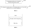
- FIG. 4 is a flowchart of a network operation method according to an embodiment.
- the method is applicable to the scenario in which the trunk mode is supported in the virtualized environment.
- the method may include the following:
- a management node receives virtualized network function information.
- the virtualized network function information may carry at least one dynamic network change flag.
- the dynamic network change flag can explicitly indicate in the trunk mode whether the service software currently supports the processing of a data stream change caused by a dynamic network change.
- the dynamic network change flag is 0 or false, it indicates that the service software does not support a data stream change caused by a network change and the management node cannot initiate a change to an accessed network.
- the dynamic network change flag is 1 or true, it indicates that the service software supports the data stream change caused by the network change and the management node can initiate the change to the accessed network.
- the management node operates on a first-type network according to the virtualized network function information.
- the first-type network in S402 may be a network created by MANO according to a network attribute defined in the ETSI NFV specifications.
- the network attribute may be a description of a network attribute which is described in a virtualized network function descriptor (VNFD) and supported by a VNF and a network attribute which is in a network service descriptor (NSD) and describes the interconnection between a VNF instance and another VNF ⁇ PNF, or a related parameter of a network which is added by a network management node and connected to a virtualized network function instance, for example, a related parameter of a network which is added by an OSS/BSS of the network management node in an NSD design phase and connected to the virtualized network function instance.
- VNFD virtualized network function descriptor
- NSD network service descriptor
- the management node After acquiring the at least one dynamic network change flag carried in the virtualized network function information, the management node may operate on a created first-type network.
- the preceding first-type network may be one or more networks. That is, two or more networks created according to the network attribute defined in the ETSI NFV specifications may be collectively referred to as first-type networks.
- the management node after receiving the virtualized network function information, the management node operates on the first-type network according to the virtualized network function information. Since the at least one dynamic network change flag carried in the virtualized network function information can be used for indicating whether the dynamic network change is supported, the management node can correctly process a change requirement of the first-type network according to the virtualized network function information.
- the virtualized network function information received in S401 may carry at least one mode flag used for indicating whether the trunk mode is supported.
- the virtualized network function information may also carry a restriction characteristic parameter for a network connection, where the parameter may be the number of access ports, the type of the first-type network (for example, a virtual local area network (VLAN), a Virtual eXtensible Local Area Network (VXLAN), or the Generic Routing Encapsulation (GRE)), a protocol stack structure of the accessed network (for example, media access control (MAC) ⁇ the Internet Protocol (IP) ⁇ the User Datagram Protocol (UDP), or the MAC ⁇ IP ⁇ Transmission Control Protocol (TCP)).
- VLAN virtual local area network
- VXLAN Virtual eXtensible Local Area Network
- GRE Generic Routing Encapsulation
- MAC media access control
- IP Internet Protocol
- UDP User Datagram Protocol
- TCP Transmission Control Protocol
- the preceding S402 may be that the network management node creates a virtualized network function instance according to the virtualized network function information and connects the first-type network according to the virtualized network function instance. Further, when the first-type network runs, the network management node operates on a connection relationship between the virtualized network function instance and the first-type network according to the at least one dynamic network change flag.
- the network management node may include the OSS/BSS and the MANO.
- the network management node may include other units and modules, which is not limited in the embodiments of the present application.
- the OSS/BSS may manage the virtualized network function information as part of the NSD or manage the virtualized network function information independently.
- the OSS/BSS may carry acquired network connection information in the NSD.
- the OSS/BSS uploads the virtualized network function information to the MANO so that the MANO instantiates the virtualized network function instance according to the virtualized network function information.
- the uploading of the virtualized network function information by the OSS/BSS to the MANO in the preceding description may be part of an operation of uploading the NSD or may be an independent management operation of the virtualized network function information.
- the instantiation process may be that the MANO creates a vSwitch, where a trunk port of the vSwitch is connected to the virtualized network function instance. Further, the MANO connects the virtualized network function instance to the first-type network, and the OSS/BSS and the MANO record the dynamic network change flag in the virtualized network function information. If a network needs to be added, the MANO creates a required access port to be connected to the network. The required access port is created according to the restriction characteristic parameter for the network connection in the virtualized network function information.
- that the network management node operates on the connection relationship between the virtualized network function instance and the first-type network according to the at least one dynamic network change flag may be that the network management node operates on the connection relationship between the virtualized network function instance and the first-type network according to a dynamic network change flag of at least one connection module.
- connection relationship between the virtualized network function instance and the first-type network may be a relationship that the virtualized network function instance is connected to the first-type network through the connection module.
- the connection module may include a VNF module and/or a virtualized network function component (VNFC) and/or a CP.
- VNF module may consist of one or more VNFCs, and one VNFC may be connected to one or more CPs connected to the trunk port of the vSwitch.
- the preceding at least one dynamic network change flag may be added to a connection point descriptor (CPD) in the ETSI specifications. Therefore, the management node may operate, at least through the dynamic network change flag, on the connection relationship between the virtualized network function instance and the first-type network which are connected through the CP.
- CPD connection point descriptor
- the network management node may operate on the connection relationship between the virtualized network function instance and the first-type network according to the dynamic network change flag of the at least one connection module in implementation manners described below.
- the network management node does not change the connection relationship between the virtualized network function instance and the first-type network.
- the network management node changes the connection relationship between the virtualized network function instance and the first-type network.
- the network management node does not change the connection relationship between the virtualized network function instance and the first-type network.
- the VNF module needs to support the connections of multiple first-type networks
- the mode flag carried in the virtualized network function information indicates that the trunk mode is supported, that is, the first-type networks may be connected through access ports of the vSwitch
- a dynamic network flag of the virtualized network function instance indicates that the dynamic network change is not supported.
- the network management node does not change the connection relationship between the virtualized network function instance and the first-type network, that is, the network management node refuses to modify connection relationships between the virtualized network function instance and network 1, network 2, ... , and network n.
- the preceding change operation on the connection relationship between the virtualized network function instance and the first-type network may exceed limitations to the support capabilities of the service software set in the virtualized network function module.
- the number of access ports limited by the virtualized network function module is exceeded, an attribute of a network connected through an access port is changed, or the like.
- the network management node may change the connection relationship between the virtualized network function instance and the first-type network in cases described below.
- the VNF consists of three VNFCs, that is, VNFC1, VNFC2, and VNFC3, respectively, first-type networks connected to VNFC1 are network e and network f, first-type networks connected to VNFC2 are network c and network d, and first-type networks connected to VNFC3 are network a and network b.
- Mode flags for VNFC1 and VNFC2 indicate that the trunk mode is supported.
- a mode flag for VNFC3 indicates that the trunk mode is not supported.
- a dynamic network change flag for VNFC1 indicates that the dynamic change is supported and a dynamic network change flag for VNFC2 indicates that the dynamic change is not supported.
- VNFC1 and VNFC2 may be connected to network e and network f and network c and network d through the access ports of the vSwitch, respectively; and VNFC3 is connected to network a and network b through multiple virtual networks.
- the management node may learn that VNFC1 uses the trunk mode and supports the dynamic network change; VNFC2 uses the trunk mode and does not support the dynamic network change; and VNFC3 does not use the trunk mode.
- the network management node may learn, according to the virtualized network function information, that a network change operation can be performed merely on VNFC1 which supports the dynamic network change, that is, connection relationships between VNFC1 and the first-type networks e and f are changed. For example, network g is added to VNFC1, network e is deleted, or the like.
- the VNF module needs to support the connections of multiple networks, information about the connected networks is changeable, the mode flag carried in the virtualized network function information indicates that the trunk mode is supported, that is, the first-type network can be connected through the access port of the vSwitch, and at least one dynamic network flag indicates that the dynamic network change is supported.
- the network management node changes the connection relationship between the virtualized network function instance and the first-type network.
- the network management node may initiate an instruction to add a new network connection through the OSS/BSS within the network management node so that the OSS/BSS and the MANO cooperate with each other to create a new access port on the vSwitch connected to the virtualized network function instance, connect the access port to network m, and notify service processing software of the virtualized network function instance of related parameters of network m.
- the preceding network m may be a network already created or may be a network specially created for a virtual network instance.
- the network management node may initiate an instruction to delete a network connection through the OSS/BSS within the network management node so that the OSS/BSS and the MANO cooperate with each other to break a connection between the virtualized network function instance and network n, delete a corresponding access port on the vSwitch connected to the virtualized network function module, and notify the service processing software of the virtualized network function instance that network n is not within the processing range of the service processing software.
- the VNF module needs to support the connections of multiple networks, virtualized network function instance 1 is connected to network 1 and network 2, virtualized network function instance 2 is connected to network n and network m, the information about the connected networks are changeable, the mode flag carried in the virtualized network function information indicates that the trunk mode is supported, that is, the first-type network may be connected through the access port of the vSwitch, and at least one dynamic network flag indicates that the dynamic network change is supported.
- the network management node changes the connection relationship between the virtualized network function instance and the first-type network.
- the OSS/BSS and the MANO cooperate with each other to perform the following process: a connection between virtualized network function instance 2 and network n is broken; an access port of the vSwitch for virtualized network function instance 2 is deleted; service processing software of virtualized network function instance 2 is notified that network n is not within the processing range of the service processing software; a new access port is created on a vSwitch connected to virtualized network function instance 1 and then connected to network n; and service processing software of virtualized network function instance 1 is notified of related parameters of network n, thereby changing the connection relationship between network n and virtualized network function instance 2.
- the trigger condition satisfied by the network data stream may be that a running overhead of virtualized network function instance 2 is overloaded and the data stream needs to be distributed to virtualized network function instance 1 with a low running overhead, that a fault occurs during the running of virtualized network function instance 2 and the data stream is distributed to virtualized network function instance 1 which normally runs so as to ensure that a service is not affected, or that both virtualized network function instance 1 and virtualized network function instance 2 are running with low loads, a dynamic capacity expansion management module in the management node determines to reduce a capacity of virtualized network function instance 2, and the data stream on virtualized network function instance 2 is distributed to virtualized network function instance 1.
- the preceding trigger condition is merely for an illustrative description. If other trigger conditions are satisfied, the change of the connection relationship between the virtualized network function instance and the first-type network by the example process shown in FIG. 9 is within the scope of the present application.
- the VNF module needs to support the connections of multiple networks, virtualized network function instance 1 is connected to network 1 and network 2, virtualized network function instance 2 is connected to network n and network m, the information about the connected networks are changeable, the mode flag carried in the virtualized network function information indicates that the trunk mode is supported, that is, the first-type network may be connected through the access port of the vSwitch, and at least one dynamic network flag indicates that the dynamic network change is supported.
- the network management node does not change the connection relationship between the virtualized network function instance and the first-type network.
- the network management node does not change connection relationships between virtualized network function instance 1 and network 1 and network 2 when the virtualized network function information is designed to be that information for virtualized network function instance 1 satisfies the preset condition (for example, a first-type network with a high priority is connected to virtualized network function instance 1, or a user with a high priority accesses a first-type network connected to virtualized network function instance 1).
- the preset condition for example, a first-type network with a high priority is connected to virtualized network function instance 1, or a user with a high priority accesses a first-type network connected to virtualized network function instance 1.
- the OSS/BSS determines that the connection relationships between virtualized network function instance 1 and network 1 and network 2 are not changed while merely connection relationships between virtualized network function instance 2 and network n and network m are allowed to be changed. That is, during the orchestration and management by the MANO, a triggered network change can be performed merely on virtualized network function instance 2. For example, the network change is implemented through the addition or deletion of an access port on the vSwitch.
- FIG. 11 is a structure diagram of a network operation apparatus according to an embodiment.
- the apparatus includes a receiving module 1101 and an operation module 1102.
- the receiving module is configured to receive virtualized network function information which carries at least one dynamic network change flag.
- the at least one dynamic network change flag is used for indicating whether a dynamic network change is supported.
- the operation module is configured to operate on a first-type network according to the virtualized network function information.
- the preceding operation module includes a creation unit, a connection unit, and an operation unit.
- the creation unit is configured to create a virtualized network function instance according to the virtualized network function information.
- the connection unit is configured to connect the first-type network according to the virtualized network function instance.
- the operation unit is configured to operate on a connection relationship between the virtualized network function instance and the first-type network according to the at least one dynamic network change flag when the first-type network runs.
- the preceding operation unit may be specifically configured to operate on the connection relationship between the virtualized network function instance and the first-type network according to a dynamic network change flag of at least one connection module.
- the virtualized network function instance is connected to the first-type network through the connection module, and the connection module includes a virtualized network function module and/or a virtualized network function component and/or a connection point.
- the operation unit When the dynamic network change flag of the connection module indicates that the dynamic network change is not supported, the operation unit is configured to not change the connection relationship between the virtualized network function instance and the first-type network. Alternatively, when the dynamic network change flag of the connection module indicates that the dynamic network change is supported, the operation unit is configured to change the connection relationship between the virtualized network function instance and the first-type network.
- that the operation unit is configured to change the connection relationship between the virtualized network function instance and the first-type network may be that the operation unit changes the connection relationship between the virtualized network function instance and the first-type network when the network operation apparatus receives a network change request.
- that the operation unit is configured to change the connection relationship between the virtualized network function instance and the first-type network may be that the operation unit changes the connection relationship between the virtualized network function instance and the first-type network when a network data stream satisfies a trigger condition.
- the operation unit when the dynamic network change flag of the connection module indicates that the dynamic network change is supported and the virtualized network function information satisfies a preset condition, the operation unit is configured to not change the connection relationship between the virtualized network function instance and the first-type network.
- FIG. 12 is a structure diagram of a management node device according to an embodiment.
- the device includes a processor 1201 and a memory 1202.
- One or more processors 1201 may be in the device, and one processor 1201 is shown as an example in FIG. 12 .
- the processor 1201 and the memory 1202 in the device may be connected through a bus or in other manners. In FIG. 12 , the connection through the bus is shown as an example.
- the memory 1202 may be configured to store software programs, computer-executable programs, and modules, such as program instructions/modules corresponding to the network operation method in the embodiment of the present application in FIG. 4 (for example, the receiving module 1101 and the operation module 1102 in the network operation apparatus).
- the processor 1201 executes software programs, instructions, and modules stored in the memory 1202 so that the preceding network operation method is implemented.
- the memory 1202 may mainly include a program storage region and a data storage region.
- the program storage region may store an operating system and an application program required for at least one function
- the data storage region may store data or the like created according to the use of the device.
- the memory 1202 may include a high-speed random-access memory and may also include a non-volatile memory such as at least one magnetic disk memory, a flash memory, or another non-volatile solid-state memory.
- An embodiment of the present application further provides a storage medium including computer-executable instructions which are used for performing a network operation method when executed by a computer processor.
- the method includes the following: A management node receives virtualized network function information carrying at least one dynamic network change flag. The at least one dynamic network change flag is used for indicating whether a dynamic network change is supported.
- the management node operates on a first-type network according to the virtualized network function information.
- various embodiments of the present application may be implemented in hardware, a dedicated circuit, software, logics, or any combination thereof.
- some aspects may be implemented in hardware while other aspects may be implemented in firmware or software executable by a controller, a microprocessor, or other computing devices, although the present application is not limited thereto.
- the embodiments of the present application may be implemented through the execution of computer program instructions by a data processor of a network operation apparatus, for example, implemented in a processor entity, hardware, or a combination of software and hardware.
- the computer program instructions may be assembly instructions, instruction set architecture (ISA) instructions, machine instructions, machine-related instructions, microcodes, firmware instructions, state setting data, or source or object codes written in any combination of one or more programming languages.
- a block diagram of any logic flow among the drawings of the present application may represent program steps, or may represent interconnected logic circuits, modules, and functions, or may represent a combination of program steps and logic circuits, modules, and functions.
- Computer programs may be stored on a memory.
- the memory may be of any type suitable for a local technical environment and may be implemented using any suitable data storage technology, such as, but not limited to, a read-only memory (ROM), a random-access memory (RAM), and an optical memory device and system (digital video disc (DVD) or compact disc (CD)).
- Computer-readable media may include non-transitory storage media.
- the data processor may be of any type suitable for the local technical environment, such as, but not limited to, a general-purpose computer, a special-purpose computer, a microprocessor, a digital signal processor (DSP), an application-specific integrated circuit (ASIC), a field-programmable gate array (FPGA), and a processor based on multi-core processor architecture.
- a general-purpose computer such as, but not limited to, a general-purpose computer, a special-purpose computer, a microprocessor, a digital signal processor (DSP), an application-specific integrated circuit (ASIC), a field-programmable gate array (FPGA), and a processor based on multi-core processor architecture.
- DSP digital signal processor
- ASIC application-specific integrated circuit
- FPGA field-programmable gate array
Landscapes
- Engineering & Computer Science (AREA)
- Computer Networks & Wireless Communication (AREA)
- Signal Processing (AREA)
- Data Exchanges In Wide-Area Networks (AREA)
Abstract
Description
- This application claims priority to
Chinese Patent Application No. 201911205628.4 filed with the China National Intellectual Property Administration (CNIPA) on Nov. 29, 2019 - The present application relates to the technical field of communication, for example, a network operation method and apparatus, a device, and a storage medium.
- Network functions virtualization (NFV) is software processing technology that carries other functions by use of general-purpose hardware and virtualization technology and is mainly used to reduce the costs of a network device. The NFV may make the functions of the network device no longer depend on specific-purpose hardware by means of software and hardware decoupling and function abstraction so that resources can be sufficiently and flexibly shared, new services can be rapidly developed and deployed, and automatic deployment, auto scaling, fault isolation and self-healing, and the like are performed based on actual service requirements.
- As shown in
FIG. 1 , the NFV system architecture defined by the European Telecommunications Standards Institute (ETSI) mainly includes an operations support system (OSS)/business support system (BSS), a virtualized network function (VNF), a network functions virtualization infrastructure (NFVI), and a Network Functions Virtualization Management and Orchestration (NFV-MANO) system. The NFVI comprehensively virtualizes hardware resources for computing, storage, and a network and maps the hardware resources into virtual resources. The VNF runs on the NFVI, adopts the virtual resources after virtualization by the NFVI, and implements various conventional physical network functions by use of software. The NFV-MANO manages and orchestrates a relationship between the VNF and the VNFI, a relationship between VNFs, and a relationship between the VNF and another physical network function (PNF). - The NFV-MANO includes a Virtualized Infrastructure Manager (VIM), a Virtualized Network Function Manager (VNFM), and a Network Function Virtualization Orchestrator (NFVO). The VIM is configured to control and manage virtualized resources. The VNFM is configured to manage a life cycle of the VNF. The NFVO is configured to orchestrate and manage a virtual infrastructure and manage a life cycle of a network service (NS).
- In a non-virtualized application, ports of a switch may be classified into two types: an access port and a trunk port. As shown in
FIG. 2 , merely messages belonging to one virtual local area network (VLAN) are allowed to pass through the access port. When the access port is used, if messages need to be exchanged between two switches, different ports on the two switches need to be allocated to messages of different VLANs for separate connections. However, the switch has limited ports and the limited ports of the switch will be wasted in this interconnection manner. However, messages of multiple VLANs are allowed to pass through the trunk port. When the trunk port is used, merely one port is required to allocated to each switch as the trunk port so that the messages of different VLANs can be transmitted, thereby saving ports of the switch. - In a virtualized application, a virtualized switch (vSwitch) of the NFVI can already implement ports which support a trunk mode. As shown in
FIG. 3 , before the trunk mode is supported, when a virtual machine needs to access multiple networks, the virtual machine needs to be configured with multiple virtual network interface cards (vNICs) to respectively access different networks. In addition, accessed networks may be added or deleted merely in the manner of adding or deleting vNICs. However, changing the vNIC of the virtual machine may trigger a re-instantiation process of the virtual machine itself and the restart of running service software, resulting in the interruption of the VNF. However, after the trunk mode is supported, merely one vNIC needs to be configured for the virtual machine. After the vNIC is connected to a trunk port of the vSwitch, different networks can be accessed through different access ports of the vSwitch, thereby reducing the number of vNICs configured for the virtual machine and providing the virtual machine with the capability to dynamically change a connected network during running of the virtual machine after successful instantiation. - However, in the ETSI NFV specifications, it is merely defined whether external connection points (CPs) of the virtual machine support operation in the trunk mode, that is, whether a port supports the transmission of messages of multiple VLANs. Other issues in the ETSI NFV specifications have not been discussed.
- Embodiments of the present application provide a network operation method. The method includes the following:
A management node receives virtualized network function (VNF) information carrying at least one dynamic network change flag. - The at least one dynamic network change flag is used for indicating whether a dynamic network change is supported.
- The management node operates on a first-type network according to the virtualized network function information.
- Embodiments of the present application further provide a network operation apparatus including a receiving module and an operation module.
- The receiving module is configured to receive virtualized network function information carrying at least one dynamic network change flag.
- The at least one dynamic network change flag is used for indicating whether a dynamic network change is supported.
- The operation module is configured to operate on a first-type network according to the virtualized network function information.
- Embodiments of the present application further provide a management node device.
- The management node device includes a memory, a processor, and a computer program stored in the memory and executable by the processor. When executing the computer program, the processor implements the network operation method according to the embodiments of the present application.
- Embodiments of the present application further provide a computer-readable storage medium storing a computer program which, when executed by a processor, implements the network operation method according to the embodiments of the present application.
-
-
FIG. 1 is a diagram of an ETSI NFV system architecture; -
FIG. 2 is a comparison diagram of an access port and a trunk port in a non-virtualized environment; -
FIG. 3 is a comparison diagram of a virtual machine which uses a trunk mode and a virtual machine which does not use the trunk mode; -
FIG. 4 is a flowchart of a network operation method according to an embodiment; -
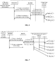
FIG. 5 is a structure diagram of virtualized network function information; -
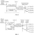
FIG. 6 is a flowchart of a network operation method according to an embodiment; -
FIG. 7 is a flowchart of another network operation method according to an embodiment; -
FIG. 8 is a flowchart of another network operation method according to an embodiment; -
FIG. 9 is a flowchart of another network operation method according to an embodiment; -
FIG. 10 is a flowchart of another network operation method according to an embodiment; -
FIG. 11 is a structure diagram of a network operation apparatus according to an embodiment; and -
FIG. 12 is a structure diagram of a management node device according to an embodiment. - Embodiments of the present application are described below in conjunction with drawings.
- In addition, in the embodiments of the present application, the words such as "optionally" or "for example" refer to that an example, an instance, or an illustration is provided.
- To understand solutions provided in the embodiments of the present application, related concepts which may be involved in the embodiments of the present application are explained and described herein. An example is provided below.
- A virtual machine provides the capability to dynamically change an accessed network. This capability is not equivalent to the capability of a virtualized switch connected to the virtual machine to dynamically create or delete an access port. This capability indicates that service software running on the virtual machine needs to process dynamically changing data streams from different networks, that is, the service software running on the virtual machine is required to have a data processing capability matching the accessed network. Otherwise, the function of dynamically changing the accessed network in a trunk mode in a virtualized environment is incompletely implemented.
- Based on the preceding concept,
FIG. 4 is a flowchart of a network operation method according to an embodiment. The method is applicable to the scenario in which the trunk mode is supported in the virtualized environment. As shown inFIG. 4 , the method may include the following:
In S401, a management node receives virtualized network function information. - In this embodiment, the virtualized network function information may carry at least one dynamic network change flag. As shown in
FIG. 5 , the dynamic network change flag can explicitly indicate in the trunk mode whether the service software currently supports the processing of a data stream change caused by a dynamic network change. - For example, it is assumed that when the dynamic network change flag is 0 or false, it indicates that the service software does not support a data stream change caused by a network change and the management node cannot initiate a change to an accessed network. When the dynamic network change flag is 1 or true, it indicates that the service software supports the data stream change caused by the network change and the management node can initiate the change to the accessed network.
- In S402, the management node operates on a first-type network according to the virtualized network function information.
- The first-type network in S402 may be a network created by MANO according to a network attribute defined in the ETSI NFV specifications. The network attribute may be a description of a network attribute which is described in a virtualized network function descriptor (VNFD) and supported by a VNF and a network attribute which is in a network service descriptor (NSD) and describes the interconnection between a VNF instance and another VNF\PNF, or a related parameter of a network which is added by a network management node and connected to a virtualized network function instance, for example, a related parameter of a network which is added by an OSS/BSS of the network management node in an NSD design phase and connected to the virtualized network function instance.
- After acquiring the at least one dynamic network change flag carried in the virtualized network function information, the management node may operate on a created first-type network.
- The preceding first-type network may be one or more networks. That is, two or more networks created according to the network attribute defined in the ETSI NFV specifications may be collectively referred to as first-type networks.
- In the embodiments of the present application, after receiving the virtualized network function information, the management node operates on the first-type network according to the virtualized network function information. Since the at least one dynamic network change flag carried in the virtualized network function information can be used for indicating whether the dynamic network change is supported, the management node can correctly process a change requirement of the first-type network according to the virtualized network function information.
- In an example, the virtualized network function information received in S401 may carry at least one mode flag used for indicating whether the trunk mode is supported. The virtualized network function information may also carry a restriction characteristic parameter for a network connection, where the parameter may be the number of access ports, the type of the first-type network (for example, a virtual local area network (VLAN), a Virtual eXtensible Local Area Network (VXLAN), or the Generic Routing Encapsulation (GRE)), a protocol stack structure of the accessed network (for example, media access control (MAC)\the Internet Protocol (IP)\the User Datagram Protocol (UDP), or the MAC\IP\Transmission Control Protocol (TCP)).
- In an example, the preceding S402 may be that the network management node creates a virtualized network function instance according to the virtualized network function information and connects the first-type network according to the virtualized network function instance. Further, when the first-type network runs, the network management node operates on a connection relationship between the virtualized network function instance and the first-type network according to the at least one dynamic network change flag.
- The network management node may include the OSS/BSS and the MANO. The network management node may include other units and modules, which is not limited in the embodiments of the present application.
- After the network management node receives the virtualized network function information, the OSS/BSS may manage the virtualized network function information as part of the NSD or manage the virtualized network function information independently. Optionally, the OSS/BSS may carry acquired network connection information in the NSD. Further, the OSS/BSS uploads the virtualized network function information to the MANO so that the MANO instantiates the virtualized network function instance according to the virtualized network function information.
- The uploading of the virtualized network function information by the OSS/BSS to the MANO in the preceding description may be part of an operation of uploading the NSD or may be an independent management operation of the virtualized network function information.
- The instantiation process may be that the MANO creates a vSwitch, where a trunk port of the vSwitch is connected to the virtualized network function instance. Further, the MANO connects the virtualized network function instance to the first-type network, and the OSS/BSS and the MANO record the dynamic network change flag in the virtualized network function information. If a network needs to be added, the MANO creates a required access port to be connected to the network. The required access port is created according to the restriction characteristic parameter for the network connection in the virtualized network function information.
- Optionally, that the network management node operates on the connection relationship between the virtualized network function instance and the first-type network according to the at least one dynamic network change flag may be that the network management node operates on the connection relationship between the virtualized network function instance and the first-type network according to a dynamic network change flag of at least one connection module.
- The connection relationship between the virtualized network function instance and the first-type network may be a relationship that the virtualized network function instance is connected to the first-type network through the connection module.
- The connection module may include a VNF module and/or a virtualized network function component (VNFC) and/or a CP. As shown in
FIG. 5 , the VNF module may consist of one or more VNFCs, and one VNFC may be connected to one or more CPs connected to the trunk port of the vSwitch. - The preceding at least one dynamic network change flag may be added to a connection point descriptor (CPD) in the ETSI specifications. Therefore, the management node may operate, at least through the dynamic network change flag, on the connection relationship between the virtualized network function instance and the first-type network which are connected through the CP.
- In an example, the network management node may operate on the connection relationship between the virtualized network function instance and the first-type network according to the dynamic network change flag of the at least one connection module in implementation manners described below.
- In manner one, when the dynamic network change flag of the connection module indicates that the dynamic network change is not supported, the network management node does not change the connection relationship between the virtualized network function instance and the first-type network.
- In manner two, when the dynamic network change flag of the connection module indicates that the dynamic network change is supported, the network management node changes the connection relationship between the virtualized network function instance and the first-type network.
- In manner three, when the dynamic network change flag of the connection module indicates that the dynamic network change is supported, and the virtualized network function information satisfies a preset condition, the network management node does not change the connection relationship between the virtualized network function instance and the first-type network.
- As shown in
FIG. 6 , in the preceding manner one, it is assumed that in a running environment, the VNF module needs to support the connections of multiple first-type networks, the mode flag carried in the virtualized network function information indicates that the trunk mode is supported, that is, the first-type networks may be connected through access ports of the vSwitch, and a dynamic network flag of the virtualized network function instance indicates that the dynamic network change is not supported. - Then, during the running of the first-type network, after receiving the virtualized network function information, the network management node does not change the connection relationship between the virtualized network function instance and the first-type network, that is, the network management node refuses to modify connection relationships between the virtualized network function instance and
network 1,network 2, ... , and network n. - For example, the preceding change operation on the connection relationship between the virtualized network function instance and the first-type network may exceed limitations to the support capabilities of the service software set in the virtualized network function module. For example, the number of access ports limited by the virtualized network function module is exceeded, an attribute of a network connected through an access port is changed, or the like.
- In the preceding manner two, the network management node may change the connection relationship between the virtualized network function instance and the first-type network in cases described below.
- As shown in
FIG. 7 , in an example, it is assumed that the VNF consists of three VNFCs, that is, VNFC1, VNFC2, and VNFC3, respectively, first-type networks connected to VNFC1 are network e and network f, first-type networks connected to VNFC2 are network c and network d, and first-type networks connected to VNFC3 are network a and network b. Mode flags for VNFC1 and VNFC2 indicate that the trunk mode is supported. A mode flag for VNFC3 indicates that the trunk mode is not supported. In addition, a dynamic network change flag for VNFC1 indicates that the dynamic change is supported and a dynamic network change flag for VNFC2 indicates that the dynamic change is not supported. That is, VNFC1 and VNFC2 may be connected to network e and network f and network c and network d through the access ports of the vSwitch, respectively; and VNFC3 is connected to network a and network b through multiple virtual networks. - Then, after receiving the virtualized network function information, the management node may learn that VNFC1 uses the trunk mode and supports the dynamic network change; VNFC2 uses the trunk mode and does not support the dynamic network change; and VNFC3 does not use the trunk mode.
- Further, during the running of the first-type networks a to f, when receiving a network change request, the network management node may learn, according to the virtualized network function information, that a network change operation can be performed merely on VNFC1 which supports the dynamic network change, that is, connection relationships between VNFC1 and the first-type networks e and f are changed. For example, network g is added to VNFC1, network e is deleted, or the like.
- As shown in
FIG. 8 , in another example, it is assumed that in the running environment, the VNF module needs to support the connections of multiple networks, information about the connected networks is changeable, the mode flag carried in the virtualized network function information indicates that the trunk mode is supported, that is, the first-type network can be connected through the access port of the vSwitch, and at least one dynamic network flag indicates that the dynamic network change is supported. - Then, during the running of the first-type network, when receiving the network change request, the network management node changes the connection relationship between the virtualized network function instance and the first-type network.
- For example, operation and maintenance personnel add a requirement for connecting the virtualized network function instance to network m. After receiving the network change request, the network management node may initiate an instruction to add a new network connection through the OSS/BSS within the network management node so that the OSS/BSS and the MANO cooperate with each other to create a new access port on the vSwitch connected to the virtualized network function instance, connect the access port to network m, and notify service processing software of the virtualized network function instance of related parameters of network m.
- The preceding network m may be a network already created or may be a network specially created for a virtual network instance.
- Alternatively, the operation and maintenance personnel design as required that the virtualized network function instance no longer processes data on network n. Then, after receiving the network change request, the network management node may initiate an instruction to delete a network connection through the OSS/BSS within the network management node so that the OSS/BSS and the MANO cooperate with each other to break a connection between the virtualized network function instance and network n, delete a corresponding access port on the vSwitch connected to the virtualized network function module, and notify the service processing software of the virtualized network function instance that network n is not within the processing range of the service processing software.
- As shown in
FIG. 9 , in an example, it is assumed that in the running environment, the VNF module needs to support the connections of multiple networks, virtualizednetwork function instance 1 is connected tonetwork 1 andnetwork 2, virtualizednetwork function instance 2 is connected to network n and network m, the information about the connected networks are changeable, the mode flag carried in the virtualized network function information indicates that the trunk mode is supported, that is, the first-type network may be connected through the access port of the vSwitch, and at least one dynamic network flag indicates that the dynamic network change is supported. - Then, during the running of the first-type network, when a network data stream satisfies a trigger condition, the network management node changes the connection relationship between the virtualized network function instance and the first-type network.
- For example, when the MANO in the network management node detects during orchestration and management that the network data stream satisfies the trigger condition and virtualized
network function instance 1 needs to take over a data stream of network n, the OSS/BSS and the MANO cooperate with each other to perform the following process: a connection between virtualizednetwork function instance 2 and network n is broken; an access port of the vSwitch for virtualizednetwork function instance 2 is deleted; service processing software of virtualizednetwork function instance 2 is notified that network n is not within the processing range of the service processing software; a new access port is created on a vSwitch connected to virtualizednetwork function instance 1 and then connected to network n; and service processing software of virtualizednetwork function instance 1 is notified of related parameters of network n, thereby changing the connection relationship between network n and virtualizednetwork function instance 2. - For example, in the preceding process, the trigger condition satisfied by the network data stream may be that a running overhead of virtualized
network function instance 2 is overloaded and the data stream needs to be distributed to virtualizednetwork function instance 1 with a low running overhead, that a fault occurs during the running of virtualizednetwork function instance 2 and the data stream is distributed to virtualizednetwork function instance 1 which normally runs so as to ensure that a service is not affected, or that both virtualizednetwork function instance 1 and virtualizednetwork function instance 2 are running with low loads, a dynamic capacity expansion management module in the management node determines to reduce a capacity of virtualizednetwork function instance 2, and the data stream on virtualizednetwork function instance 2 is distributed to virtualizednetwork function instance 1. - The preceding trigger condition is merely for an illustrative description. If other trigger conditions are satisfied, the change of the connection relationship between the virtualized network function instance and the first-type network by the example process shown in
FIG. 9 is within the scope of the present application. - As shown in
FIG. 10 , in manner three, it is assumed that in the running environment, the VNF module needs to support the connections of multiple networks, virtualizednetwork function instance 1 is connected tonetwork 1 andnetwork 2, virtualizednetwork function instance 2 is connected to network n and network m, the information about the connected networks are changeable, the mode flag carried in the virtualized network function information indicates that the trunk mode is supported, that is, the first-type network may be connected through the access port of the vSwitch, and at least one dynamic network flag indicates that the dynamic network change is supported. - Then, during the running of
network 1,network 2, network n, and network m, when the dynamic network flag for the virtualized network function instance indicates that the dynamic network change is supported and the virtualized network function information satisfies the preset condition, the network management node does not change the connection relationship between the virtualized network function instance and the first-type network. - For example, though the dynamic network flag of virtualized
network function instance 1 indicates that the dynamic network change is supported, the network management node does not change connection relationships between virtualizednetwork function instance 1 andnetwork 1 andnetwork 2 when the virtualized network function information is designed to be that information for virtualizednetwork function instance 1 satisfies the preset condition (for example, a first-type network with a high priority is connected to virtualizednetwork function instance 1, or a user with a high priority accesses a first-type network connected to virtualized network function instance 1). - In this case, when the operation and maintenance personnel initiate the network change request, the OSS/BSS determines that the connection relationships between virtualized
network function instance 1 andnetwork 1 andnetwork 2 are not changed while merely connection relationships between virtualizednetwork function instance 2 and network n and network m are allowed to be changed. That is, during the orchestration and management by the MANO, a triggered network change can be performed merely on virtualizednetwork function instance 2. For example, the network change is implemented through the addition or deletion of an access port on the vSwitch. - The preceding preset conditions are merely for an illustrative description and are not limited in the embodiments of the present application.
-
FIG. 11 is a structure diagram of a network operation apparatus according to an embodiment. As shown inFIG. 11 , the apparatus includes areceiving module 1101 and anoperation module 1102. The receiving module is configured to receive virtualized network function information which carries at least one dynamic network change flag. The at least one dynamic network change flag is used for indicating whether a dynamic network change is supported. - The operation module is configured to operate on a first-type network according to the virtualized network function information.
- The preceding operation module includes a creation unit, a connection unit, and an operation unit. The creation unit is configured to create a virtualized network function instance according to the virtualized network function information. The connection unit is configured to connect the first-type network according to the virtualized network function instance. The operation unit is configured to operate on a connection relationship between the virtualized network function instance and the first-type network according to the at least one dynamic network change flag when the first-type network runs.
- The preceding operation unit may be specifically configured to operate on the connection relationship between the virtualized network function instance and the first-type network according to a dynamic network change flag of at least one connection module. The virtualized network function instance is connected to the first-type network through the connection module, and the connection module includes a virtualized network function module and/or a virtualized network function component and/or a connection point.
- When the dynamic network change flag of the connection module indicates that the dynamic network change is not supported, the operation unit is configured to not change the connection relationship between the virtualized network function instance and the first-type network. Alternatively, when the dynamic network change flag of the connection module indicates that the dynamic network change is supported, the operation unit is configured to change the connection relationship between the virtualized network function instance and the first-type network.
- In an example, that the operation unit is configured to change the connection relationship between the virtualized network function instance and the first-type network may be that the operation unit changes the connection relationship between the virtualized network function instance and the first-type network when the network operation apparatus receives a network change request.
- In an example, that the operation unit is configured to change the connection relationship between the virtualized network function instance and the first-type network may be that the operation unit changes the connection relationship between the virtualized network function instance and the first-type network when a network data stream satisfies a trigger condition.
- In an example, when the dynamic network change flag of the connection module indicates that the dynamic network change is supported and the virtualized network function information satisfies a preset condition, the operation unit is configured to not change the connection relationship between the virtualized network function instance and the first-type network.
-
FIG. 12 is a structure diagram of a management node device according to an embodiment. As shown inFIG. 12 , the device includes aprocessor 1201 and amemory 1202. One ormore processors 1201 may be in the device, and oneprocessor 1201 is shown as an example inFIG. 12 . Theprocessor 1201 and thememory 1202 in the device may be connected through a bus or in other manners. InFIG. 12 , the connection through the bus is shown as an example. - The
memory 1202, as a computer-readable storage medium, may be configured to store software programs, computer-executable programs, and modules, such as program instructions/modules corresponding to the network operation method in the embodiment of the present application inFIG. 4 (for example, thereceiving module 1101 and theoperation module 1102 in the network operation apparatus). Theprocessor 1201 executes software programs, instructions, and modules stored in thememory 1202 so that the preceding network operation method is implemented. - The
memory 1202 may mainly include a program storage region and a data storage region. The program storage region may store an operating system and an application program required for at least one function, and the data storage region may store data or the like created according to the use of the device. In addition, thememory 1202 may include a high-speed random-access memory and may also include a non-volatile memory such as at least one magnetic disk memory, a flash memory, or another non-volatile solid-state memory. - An embodiment of the present application further provides a storage medium including computer-executable instructions which are used for performing a network operation method when executed by a computer processor. The method includes the following:
A management node receives virtualized network function information carrying at least one dynamic network change flag. The at least one dynamic network change flag is used for indicating whether a dynamic network change is supported. The management node operates on a first-type network according to the virtualized network function information. - The above are merely example embodiments of the present application and are not intended to limit the scope of the present application.
- Generally, various embodiments of the present application may be implemented in hardware, a dedicated circuit, software, logics, or any combination thereof. For example, some aspects may be implemented in hardware while other aspects may be implemented in firmware or software executable by a controller, a microprocessor, or other computing devices, although the present application is not limited thereto.
- The embodiments of the present application may be implemented through the execution of computer program instructions by a data processor of a network operation apparatus, for example, implemented in a processor entity, hardware, or a combination of software and hardware. The computer program instructions may be assembly instructions, instruction set architecture (ISA) instructions, machine instructions, machine-related instructions, microcodes, firmware instructions, state setting data, or source or object codes written in any combination of one or more programming languages.
- A block diagram of any logic flow among the drawings of the present application may represent program steps, or may represent interconnected logic circuits, modules, and functions, or may represent a combination of program steps and logic circuits, modules, and functions. Computer programs may be stored on a memory. The memory may be of any type suitable for a local technical environment and may be implemented using any suitable data storage technology, such as, but not limited to, a read-only memory (ROM), a random-access memory (RAM), and an optical memory device and system (digital video disc (DVD) or compact disc (CD)). Computer-readable media may include non-transitory storage media. The data processor may be of any type suitable for the local technical environment, such as, but not limited to, a general-purpose computer, a special-purpose computer, a microprocessor, a digital signal processor (DSP), an application-specific integrated circuit (ASIC), a field-programmable gate array (FPGA), and a processor based on multi-core processor architecture.
Claims (10)
- A network operation method, comprising:receiving, by a management node, virtualized network function (VNF) information carrying at least one dynamic network change flag, wherein the at least one dynamic network change flag is used for indicating whether a dynamic network change is supported; andoperating, by the management node, on a first-type network according to the virtualized network function information.
- The method according to claim 1, wherein operating, by a network management node, on the first-type network according to the virtualized network function information comprises:creating, by the network management node, a virtualized network function instance according to the virtualized network function information; andconnecting, by the network management node, the first-type network according to the virtualized network function instance.
- The method according to claim 1 or 2, wherein operating, by the network management node, on the first-type network according to the virtualized network function information comprises:
in a case where the first-type network runs, operating, by the network management node, on a connection relationship between the virtualized network function instance and the first-type network according to the at least one dynamic network change flag. - The method according to claim 3, wherein operating, by the network management node, on the connection relationship between the virtualized network function instance and the first-type network according to the at least one dynamic network change flag comprises:operating, by the network management node, on the connection relationship between the virtualized network function instance and the first-type network according to a dynamic network change flag of at least one connection module;wherein the virtualized network function instance is connected to the first-type network through the connection module; andthe connection module comprises at least one of a virtualized network function module, a virtualized network function component (VNFC), or a connection point (CP).
- The method according to claim 4, wherein operating, by the network management node, on the connection relationship between the virtualized network function instance and the first-type network according to the dynamic network change flag of the at least one connection module comprises:in a case where the dynamic network change flag of the connection module indicates that the dynamic network change is not supported, not changing, by the network management node, the connection relationship between the virtualized network function instance and the first-type network; orin a case where the dynamic network change flag of the connection module indicates that the dynamic network change is supported, changing, by the network management node, the connection relationship between the virtualized network function instance and the first-type network.
- The method according to claim 5, wherein changing, by the network management node, the connection relationship between the virtualized network function instance and the first-type network comprises:in a case where the network management node receives a network change request, changing, by the network management node, the connection relationship between the virtualized network function instance and the first-type network; orin a case where a network data stream satisfies a trigger condition, changing, by the network management node, the connection relationship between the virtualized network function instance and the first-type network.
- The method according to claim 4, wherein operating, by the network management node, on the connection relationship between the virtualized network function instance and the first-type network according to the dynamic network change flag of the at least one connection module comprises:
in a case where the dynamic network change flag of the connection module indicates that the dynamic network change is supported and the virtualized network function information satisfies a preset condition, not changing, by the network management node, the connection relationship between the virtualized network function instance and the first-type network. - A network operation apparatus, comprising:a receiving module, which is configured to receive virtualized network function information carrying at least one dynamic network change flag;wherein the at least one dynamic network change flag is used for indicating whether a dynamic network change is supported; andan operation module, which is configured to operate on a first-type network according to the virtualized network function information.
- A management node device, comprising:
a memory, a processor, and a computer program stored in the memory and executable by the processor, wherein when executing the computer program, the processor implements the network operation method according to any one of claims 1 to 7. - A computer-readable storage medium, which is configured to store a computer program which, when executed by a processor, implements the network operation method according to any one of claims 1 to 7.
Applications Claiming Priority (2)
| Application Number | Priority Date | Filing Date | Title |
|---|---|---|---|
| CN201911205628.4A CN111092828B (en) | 2019-11-29 | 2019-11-29 | Network operation method, device, equipment and storage medium |
| PCT/CN2020/108582 WO2021103657A1 (en) | 2019-11-29 | 2020-08-12 | Network operation method, apparatus, and device and storage medium |
Publications (2)
| Publication Number | Publication Date |
|---|---|
| EP4068708A1 true EP4068708A1 (en) | 2022-10-05 |
| EP4068708A4 EP4068708A4 (en) | 2023-11-29 |
Family
ID=70393790
Family Applications (1)
| Application Number | Title | Priority Date | Filing Date |
|---|---|---|---|
| EP20893814.2A Pending EP4068708A4 (en) | 2019-11-29 | 2020-08-12 | Network operation method, apparatus, and device and storage medium |
Country Status (5)
| Country | Link |
|---|---|
| US (1) | US11855855B2 (en) |
| EP (1) | EP4068708A4 (en) |
| KR (1) | KR20220104241A (en) |
| CN (1) | CN111092828B (en) |
| WO (1) | WO2021103657A1 (en) |
Families Citing this family (2)
| Publication number | Priority date | Publication date | Assignee | Title |
|---|---|---|---|---|
| CN113924758A (en) * | 2019-06-04 | 2022-01-11 | 瑞典爱立信有限公司 | Method for managing port type, function manager and arranging node |
| CN111092828B (en) * | 2019-11-29 | 2024-02-23 | 中兴通讯股份有限公司 | Network operation method, device, equipment and storage medium |
Family Cites Families (17)
| Publication number | Priority date | Publication date | Assignee | Title |
|---|---|---|---|---|
| US9825856B2 (en) | 2014-01-06 | 2017-11-21 | Futurewei Technologies, Inc. | Service function chaining in a packet network |
| CN107005431B (en) | 2014-11-21 | 2020-01-31 | 华为技术有限公司 | System and method for changing service-based data plane configuration |
| CN104734931B (en) * | 2015-03-31 | 2018-06-05 | 华为技术有限公司 | Link establishing method and device between a kind of virtual network function |
| CN106161173A (en) * | 2015-04-15 | 2016-11-23 | 中兴通讯股份有限公司 | A kind of virtual network function that realizes disposes the method and device of specification configuration |
| CN106301829B (en) * | 2015-05-21 | 2019-08-09 | 华为技术有限公司 | A kind of method and apparatus of network service dilatation |
| US20160373297A1 (en) * | 2015-06-18 | 2016-12-22 | At & T Intellectual Property I, L.P. | Device, system, and method for managing virtual and physical components of a network via use of a registry |
| CN106685679A (en) * | 2015-11-09 | 2017-05-17 | 中兴通讯股份有限公司 | Network service deployment method and device |
| CN106921977B (en) * | 2015-12-26 | 2020-11-06 | 华为技术有限公司 | Service quality planning method, device and system based on service flow |
| CN106998560A (en) | 2016-01-25 | 2017-08-01 | 中兴通讯股份有限公司 | A kind of management method, the network equipment and system for virtualizing network function |
| CN107145378A (en) | 2016-03-01 | 2017-09-08 | 中兴通讯股份有限公司 | A kind of method for managing resource and device |
| CN107332750B (en) * | 2016-04-29 | 2020-10-23 | 华为技术有限公司 | Service deployment method, device and network element |
| CN108092790B (en) * | 2016-11-21 | 2020-06-09 | 大唐移动通信设备有限公司 | Management method and device |
| CN109728921B (en) * | 2017-10-27 | 2021-12-03 | 华为技术有限公司 | Management, maintenance and control method of virtual network element and related device |
| CN109995552B (en) * | 2017-12-29 | 2021-09-03 | 华为技术有限公司 | VNF service instantiation method and device |
| US11082299B2 (en) * | 2018-03-26 | 2021-08-03 | Apple Inc. | Managing virtual links in a network service instance |
| CN113924758A (en) * | 2019-06-04 | 2022-01-11 | 瑞典爱立信有限公司 | Method for managing port type, function manager and arranging node |
| CN111092828B (en) | 2019-11-29 | 2024-02-23 | 中兴通讯股份有限公司 | Network operation method, device, equipment and storage medium |
-
2019
- 2019-11-29 CN CN201911205628.4A patent/CN111092828B/en active Active
-
2020
- 2020-08-12 KR KR1020227021822A patent/KR20220104241A/en not_active Application Discontinuation
- 2020-08-12 EP EP20893814.2A patent/EP4068708A4/en active Pending
- 2020-08-12 WO PCT/CN2020/108582 patent/WO2021103657A1/en unknown
- 2020-08-12 US US17/780,944 patent/US11855855B2/en active Active
Also Published As
| Publication number | Publication date |
|---|---|
| WO2021103657A1 (en) | 2021-06-03 |
| CN111092828A (en) | 2020-05-01 |
| KR20220104241A (en) | 2022-07-26 |
| CN111092828B (en) | 2024-02-23 |
| EP4068708A4 (en) | 2023-11-29 |
| US11855855B2 (en) | 2023-12-26 |
| US20220417112A1 (en) | 2022-12-29 |
Similar Documents
| Publication | Publication Date | Title |
|---|---|---|
| US11743123B2 (en) | Managed switch architectures: software managed switches, hardware managed switches, and heterogeneous managed switches | |
| US11429408B2 (en) | System and method for network function virtualization resource management | |
| US10698717B2 (en) | Accelerator virtualization method and apparatus, and centralized resource manager | |
| US10063470B2 (en) | Data center network system based on software-defined network and packet forwarding method, address resolution method, routing controller thereof | |
| RU2571536C2 (en) | Method, system and controlling bridge for obtaining port extension topology information | |
| EP3800926A1 (en) | Alarm method and device | |
| US9690605B2 (en) | Configuration of an edge switch downlink port with a network policy of a published network configuration service type | |
| US20210149706A1 (en) | Data Processing Method and Related Device | |
| CN110262902B (en) | Information processing method and system, medium, and computing device | |
| CN111682927B (en) | Message synchronization method, device, equipment and medium based on MLAG environment | |
| EP3327994A1 (en) | Virtual network management | |
| EP3316555B1 (en) | Mac address synchronization method, device and system | |
| EP4068708A1 (en) | Network operation method, apparatus, and device and storage medium | |
| WO2017148326A1 (en) | Resource management method and device | |
| WO2019085975A1 (en) | Network topology display method and network management device | |
| WO2021063130A1 (en) | Network resource management method and system, network equipment and readable storage medium | |
| WO2018153355A1 (en) | Control information transmission method, server, and system | |
| WO2021143183A1 (en) | Method for deploying virtual machine, and related apparatus | |
| CN110795209B (en) | Control method and device | |
| US20230281033A1 (en) | Integrating virtualization and host networking | |
| CN113342456A (en) | Connection method, device, equipment and storage medium | |
| CN108886476B (en) | Multiple provider framework for virtual switch data plane and data plane migration | |
| EP4149062A1 (en) | Deployment method and apparatus for virtualized network service | |
| WO2023197815A1 (en) | Message receiving and sending method and device | |
| CN116582501B (en) | Method and system for solving slow effect of Vpc-agent network configuration based on dynamic priority |
Legal Events
| Date | Code | Title | Description |
|---|---|---|---|
| STAA | Information on the status of an ep patent application or granted ep patent |
Free format text: STATUS: THE INTERNATIONAL PUBLICATION HAS BEEN MADE |
|
| PUAI | Public reference made under article 153(3) epc to a published international application that has entered the european phase |
Free format text: ORIGINAL CODE: 0009012 |
|
| STAA | Information on the status of an ep patent application or granted ep patent |
Free format text: STATUS: REQUEST FOR EXAMINATION WAS MADE |
|
| 17P | Request for examination filed |
Effective date: 20220624 |
|
| AK | Designated contracting states |
Kind code of ref document: A1 Designated state(s): AL AT BE BG CH CY CZ DE DK EE ES FI FR GB GR HR HU IE IS IT LI LT LU LV MC MK MT NL NO PL PT RO RS SE SI SK SM TR |
|
| DAV | Request for validation of the european patent (deleted) | ||
| DAX | Request for extension of the european patent (deleted) | ||
| REG | Reference to a national code |
Ref country code: DE Ref legal event code: R079 Free format text: PREVIOUS MAIN CLASS: H04L0012931000 Ipc: H04L0041081300 |
|
| A4 | Supplementary search report drawn up and despatched |
Effective date: 20231026 |
|
| RIC1 | Information provided on ipc code assigned before grant |
Ipc: H04L 41/40 20220101ALN20231023BHEP Ipc: H04L 41/122 20220101ALN20231023BHEP Ipc: H04L 41/0896 20220101ALN20231023BHEP Ipc: H04L 47/76 20220101ALI20231023BHEP Ipc: H04L 47/78 20220101ALI20231023BHEP Ipc: H04L 41/0895 20220101ALI20231023BHEP Ipc: H04L 41/0813 20220101AFI20231023BHEP |