EP4068702A1 - Active flow detection method, network device, and communication system - Google Patents
Active flow detection method, network device, and communication system Download PDFInfo
- Publication number
- EP4068702A1 EP4068702A1 EP20911127.7A EP20911127A EP4068702A1 EP 4068702 A1 EP4068702 A1 EP 4068702A1 EP 20911127 A EP20911127 A EP 20911127A EP 4068702 A1 EP4068702 A1 EP 4068702A1
- Authority
- EP
- European Patent Office
- Prior art keywords
- packet
- detection
- node
- situ flow
- flow metrics
- Prior art date
- Legal status (The legal status is an assumption and is not a legal conclusion. Google has not performed a legal analysis and makes no representation as to the accuracy of the status listed.)
- Withdrawn
Links
- 238000001514 detection method Methods 0.000 title claims abstract description 527
- 238000004891 communication Methods 0.000 title claims description 39
- 238000011065 in-situ storage Methods 0.000 claims abstract description 399
- 238000000034 method Methods 0.000 claims abstract description 184
- 230000015654 memory Effects 0.000 claims description 39
- 230000005540 biological transmission Effects 0.000 claims description 19
- 238000004590 computer program Methods 0.000 claims description 9
- 238000012423 maintenance Methods 0.000 claims description 6
- 238000003860 storage Methods 0.000 claims description 6
- 238000005259 measurement Methods 0.000 description 111
- 238000005516 engineering process Methods 0.000 description 31
- 238000012545 processing Methods 0.000 description 21
- 238000010586 diagram Methods 0.000 description 16
- 230000007246 mechanism Effects 0.000 description 13
- 230000008569 process Effects 0.000 description 11
- 238000004458 analytical method Methods 0.000 description 7
- 230000000694 effects Effects 0.000 description 7
- 230000006870 function Effects 0.000 description 4
- 235000008694 Humulus lupulus Nutrition 0.000 description 3
- 238000004040 coloring Methods 0.000 description 3
- 238000000691 measurement method Methods 0.000 description 2
- 238000005498 polishing Methods 0.000 description 2
- 238000004088 simulation Methods 0.000 description 2
- 238000012360 testing method Methods 0.000 description 2
- NTOPKICPEQUPPH-UHFFFAOYSA-N IPMP Natural products COC1=NC=CN=C1C(C)C NTOPKICPEQUPPH-UHFFFAOYSA-N 0.000 description 1
- 230000006399 behavior Effects 0.000 description 1
- 238000004364 calculation method Methods 0.000 description 1
- 230000008859 change Effects 0.000 description 1
- 238000011161 development Methods 0.000 description 1
- 238000005538 encapsulation Methods 0.000 description 1
- 238000011156 evaluation Methods 0.000 description 1
- 238000012544 monitoring process Methods 0.000 description 1
- 230000003287 optical effect Effects 0.000 description 1
- 230000000750 progressive effect Effects 0.000 description 1
- 238000011160 research Methods 0.000 description 1
Images







Classifications
-
- H—ELECTRICITY
- H04—ELECTRIC COMMUNICATION TECHNIQUE
- H04L—TRANSMISSION OF DIGITAL INFORMATION, e.g. TELEGRAPHIC COMMUNICATION
- H04L45/00—Routing or path finding of packets in data switching networks
- H04L45/70—Routing based on monitoring results
-
- H—ELECTRICITY
- H04—ELECTRIC COMMUNICATION TECHNIQUE
- H04L—TRANSMISSION OF DIGITAL INFORMATION, e.g. TELEGRAPHIC COMMUNICATION
- H04L43/00—Arrangements for monitoring or testing data switching networks
- H04L43/02—Capturing of monitoring data
- H04L43/026—Capturing of monitoring data using flow identification
-
- H—ELECTRICITY
- H01—ELECTRIC ELEMENTS
- H01M—PROCESSES OR MEANS, e.g. BATTERIES, FOR THE DIRECT CONVERSION OF CHEMICAL ENERGY INTO ELECTRICAL ENERGY
- H01M4/00—Electrodes
- H01M4/02—Electrodes composed of, or comprising, active material
- H01M4/13—Electrodes for accumulators with non-aqueous electrolyte, e.g. for lithium-accumulators; Processes of manufacture thereof
-
- H—ELECTRICITY
- H01—ELECTRIC ELEMENTS
- H01M—PROCESSES OR MEANS, e.g. BATTERIES, FOR THE DIRECT CONVERSION OF CHEMICAL ENERGY INTO ELECTRICAL ENERGY
- H01M4/00—Electrodes
- H01M4/02—Electrodes composed of, or comprising, active material
- H01M4/64—Carriers or collectors
-
- H—ELECTRICITY
- H04—ELECTRIC COMMUNICATION TECHNIQUE
- H04L—TRANSMISSION OF DIGITAL INFORMATION, e.g. TELEGRAPHIC COMMUNICATION
- H04L43/00—Arrangements for monitoring or testing data switching networks
- H04L43/06—Generation of reports
- H04L43/062—Generation of reports related to network traffic
-
- H—ELECTRICITY
- H04—ELECTRIC COMMUNICATION TECHNIQUE
- H04L—TRANSMISSION OF DIGITAL INFORMATION, e.g. TELEGRAPHIC COMMUNICATION
- H04L43/00—Arrangements for monitoring or testing data switching networks
- H04L43/08—Monitoring or testing based on specific metrics, e.g. QoS, energy consumption or environmental parameters
-
- H—ELECTRICITY
- H04—ELECTRIC COMMUNICATION TECHNIQUE
- H04L—TRANSMISSION OF DIGITAL INFORMATION, e.g. TELEGRAPHIC COMMUNICATION
- H04L43/00—Arrangements for monitoring or testing data switching networks
- H04L43/08—Monitoring or testing based on specific metrics, e.g. QoS, energy consumption or environmental parameters
- H04L43/0805—Monitoring or testing based on specific metrics, e.g. QoS, energy consumption or environmental parameters by checking availability
- H04L43/0817—Monitoring or testing based on specific metrics, e.g. QoS, energy consumption or environmental parameters by checking availability by checking functioning
-
- H—ELECTRICITY
- H04—ELECTRIC COMMUNICATION TECHNIQUE
- H04L—TRANSMISSION OF DIGITAL INFORMATION, e.g. TELEGRAPHIC COMMUNICATION
- H04L43/00—Arrangements for monitoring or testing data switching networks
- H04L43/08—Monitoring or testing based on specific metrics, e.g. QoS, energy consumption or environmental parameters
- H04L43/0852—Delays
- H04L43/0864—Round trip delays
-
- H—ELECTRICITY
- H04—ELECTRIC COMMUNICATION TECHNIQUE
- H04L—TRANSMISSION OF DIGITAL INFORMATION, e.g. TELEGRAPHIC COMMUNICATION
- H04L43/00—Arrangements for monitoring or testing data switching networks
- H04L43/08—Monitoring or testing based on specific metrics, e.g. QoS, energy consumption or environmental parameters
- H04L43/0876—Network utilisation, e.g. volume of load or congestion level
- H04L43/0894—Packet rate
-
- H—ELECTRICITY
- H04—ELECTRIC COMMUNICATION TECHNIQUE
- H04L—TRANSMISSION OF DIGITAL INFORMATION, e.g. TELEGRAPHIC COMMUNICATION
- H04L43/00—Arrangements for monitoring or testing data switching networks
- H04L43/14—Arrangements for monitoring or testing data switching networks using software, i.e. software packages
-
- H—ELECTRICITY
- H04—ELECTRIC COMMUNICATION TECHNIQUE
- H04L—TRANSMISSION OF DIGITAL INFORMATION, e.g. TELEGRAPHIC COMMUNICATION
- H04L45/00—Routing or path finding of packets in data switching networks
- H04L45/20—Hop count for routing purposes, e.g. TTL
-
- H—ELECTRICITY
- H04—ELECTRIC COMMUNICATION TECHNIQUE
- H04L—TRANSMISSION OF DIGITAL INFORMATION, e.g. TELEGRAPHIC COMMUNICATION
- H04L45/00—Routing or path finding of packets in data switching networks
- H04L45/38—Flow based routing
-
- H—ELECTRICITY
- H04—ELECTRIC COMMUNICATION TECHNIQUE
- H04L—TRANSMISSION OF DIGITAL INFORMATION, e.g. TELEGRAPHIC COMMUNICATION
- H04L45/00—Routing or path finding of packets in data switching networks
- H04L45/50—Routing or path finding of packets in data switching networks using label swapping, e.g. multi-protocol label switch [MPLS]
-
- H—ELECTRICITY
- H04—ELECTRIC COMMUNICATION TECHNIQUE
- H04L—TRANSMISSION OF DIGITAL INFORMATION, e.g. TELEGRAPHIC COMMUNICATION
- H04L45/00—Routing or path finding of packets in data switching networks
- H04L45/74—Address processing for routing
-
- H—ELECTRICITY
- H04—ELECTRIC COMMUNICATION TECHNIQUE
- H04L—TRANSMISSION OF DIGITAL INFORMATION, e.g. TELEGRAPHIC COMMUNICATION
- H04L47/00—Traffic control in data switching networks
- H04L47/10—Flow control; Congestion control
-
- H—ELECTRICITY
- H04—ELECTRIC COMMUNICATION TECHNIQUE
- H04L—TRANSMISSION OF DIGITAL INFORMATION, e.g. TELEGRAPHIC COMMUNICATION
- H04L12/00—Data switching networks
- H04L12/28—Data switching networks characterised by path configuration, e.g. LAN [Local Area Networks] or WAN [Wide Area Networks]
- H04L12/46—Interconnection of networks
- H04L12/4641—Virtual LANs, VLANs, e.g. virtual private networks [VPN]
-
- H—ELECTRICITY
- H04—ELECTRIC COMMUNICATION TECHNIQUE
- H04L—TRANSMISSION OF DIGITAL INFORMATION, e.g. TELEGRAPHIC COMMUNICATION
- H04L41/00—Arrangements for maintenance, administration or management of data switching networks, e.g. of packet switching networks
- H04L41/14—Network analysis or design
- H04L41/145—Network analysis or design involving simulating, designing, planning or modelling of a network
-
- H—ELECTRICITY
- H04—ELECTRIC COMMUNICATION TECHNIQUE
- H04L—TRANSMISSION OF DIGITAL INFORMATION, e.g. TELEGRAPHIC COMMUNICATION
- H04L43/00—Arrangements for monitoring or testing data switching networks
- H04L43/10—Active monitoring, e.g. heartbeat, ping or trace-route
-
- H—ELECTRICITY
- H04—ELECTRIC COMMUNICATION TECHNIQUE
- H04L—TRANSMISSION OF DIGITAL INFORMATION, e.g. TELEGRAPHIC COMMUNICATION
- H04L43/00—Arrangements for monitoring or testing data switching networks
- H04L43/20—Arrangements for monitoring or testing data switching networks the monitoring system or the monitored elements being virtualised, abstracted or software-defined entities, e.g. SDN or NFV
-
- H—ELECTRICITY
- H04—ELECTRIC COMMUNICATION TECHNIQUE
- H04L—TRANSMISSION OF DIGITAL INFORMATION, e.g. TELEGRAPHIC COMMUNICATION
- H04L43/00—Arrangements for monitoring or testing data switching networks
- H04L43/50—Testing arrangements
-
- H—ELECTRICITY
- H04—ELECTRIC COMMUNICATION TECHNIQUE
- H04L—TRANSMISSION OF DIGITAL INFORMATION, e.g. TELEGRAPHIC COMMUNICATION
- H04L45/00—Routing or path finding of packets in data switching networks
- H04L45/26—Route discovery packet
-
- H—ELECTRICITY
- H04—ELECTRIC COMMUNICATION TECHNIQUE
- H04L—TRANSMISSION OF DIGITAL INFORMATION, e.g. TELEGRAPHIC COMMUNICATION
- H04L47/00—Traffic control in data switching networks
- H04L47/10—Flow control; Congestion control
- H04L47/11—Identifying congestion
- H04L47/115—Identifying congestion using a dedicated packet
Definitions
- This application relates to the field of communications technologies, and in particular, to an active in-situ flow metrics method, a network device, and a communications system.
- Network performance detection technologies are a research hotspot in the telecommunications field.
- the network performance detection technologies analyze, control, and adjust a network running status by monitoring, measuring, and collecting network performance data, to provide stable network services. This is the basis of network running.
- the network performance detection technologies may include active metrics (English: Active Metrics) and passive metrics (English: Passive Metrics) based on measurement methods.
- Active metrics are to actively send a detection flow to a network and analyze a network behavior based on a characteristic change that occurs when the detection flow is affected by the network.
- a measured network performance indicator usually includes one or more of a packet loss rate, a delay, jitter, and bandwidth.
- Common active measurement protocols include PING, Traceroute, an Internet protocol measurement protocol (English: Internet Protocol Measurement Protocol, IPMP for short), a two-way active measurement protocol (English: Two-Way Active Measurement Protocol, OWAMP for short), and the like.
- Active metrics are flexible. However, conventional active metrics indirectly simulate a real service by sending an analog detection packet out of band. However, in this detection manner, real service traffic is not measured, consistency of the analog packet and a real service path cannot be ensured, network service quality cannot be completely and truly reflected, and accuracy of the active metrics is deviated from a real network.
- an active in-situ flow metrics method is provided.
- a head node namely, a first network node
- the method may include: The first network node generates a first analog service packet.
- the first analog service packet is not a real service packet sent by user equipment.
- the first network node generates a first detection packet.
- the first detection packet includes a first packet header and the first analog service packet, a first forwarding path that is of the first detection packet in the detection domain and that is determined based on the first analog service packet is used to simulate a forwarding path, in the detection domain, of a first real service packet sent by the user equipment, the first packet header includes first in-situ flow metrics information, the first in-situ flow metrics information is used by a node in the first forwarding path to perform in-situ flow metrics on network performance, the first in-situ flow metrics information includes first indication information, and the first indication information is used to instruct an end node in the detection domain not to forward the first detection packet to another node.
- the first network node sends the first detection packet to the end node in the detection domain along the first forwarding path.
- a current in-situ flow metrics protocol is extended, so that even in a network scenario in which there is no real service traffic, the head node in the detection domain can autonomously generate a detection packet used for in-situ flow metrics, making it possible to perform in-situ flow measurement on network performance based on an in-situ flow metrics technology. Therefore, the method provided in this embodiment of this application is equivalent to providing a new in-situ flow metrics mechanism, and only one extended in-situ flow metrics protocol needs to be configured to complete both active in-situ flow metrics and passive in-situ flow metrics, so that various scenarios of network performance detection can be covered, thereby facilitating network performance detection.
- a detection packet generated by the head node further needs to carry indication information to notify the end node that the end node receives a detection packet exclusively used for network performance measurement and indicate the end node not to forward the detection packet to another node.
- the detection packet that is not a real service packet and that is exclusively used for measurement is terminated by the end node, and is not forwarded by the end node to a node outside the detection domain, so that a real service provided for a user is prevented from being affected, thereby making the network performance detection mechanism more intelligent.
- the first packet header may include a first in-situ flow metrics header, and the first in-situ flow metrics header includes the first indication information.
- the first indication information is information indicated by at least one bit included in the first in-situ flow metrics header.
- the first in-situ flow metrics header may be a flow instruction header FIH field, and the first indication information may be a value of a flag bit R in the FIH. For example, when the value of the flag bit R is 0, it may indicate that the first detection packet is passive in-situ flow metrics. On the contrary, when the value of the flag bit R is 1, it may indicate that the first detection packet is active in-situ flow metrics.
- the first packet header may include a first extended in-situ flow metrics header, the first extended in-situ flow metrics header is used to carry the first indication information, and a type field of the first extended in-situ flow metrics header indicates that the in-situ flow metrics are active in-situ flow metrics. IFIT in-situ flow metrics are still used as an example.
- the first extended in-situ flow metrics header may be specifically an FIEH.
- the first indication information may be, for example, a value of a type field of the FIEH, and the value of the type field of the FIEH is used to indicate that the in-situ flow metrics are active in-situ flow metrics or passive in-situ flow metrics.
- the first indication information may be a value of any preset field or flag bit that may be used as an indication in the FIEH.
- the first packet header may include an option OPTION field, and the OPTION field includes the first indication information.
- the first indication information is information indicated by at least one bit included in the OPTION field.
- the first indication information is information indicated by a type field of the OPTION field, and the type field indicates that the in-situ flow metrics are active in-situ flow metrics. IFIT in-situ flow metrics are still used as an example.
- the first indication information may be specifically information indicated by a type Type field of an extended OPTION field, or the first indication information 1 may be values of one or more bits of a reserved Reserved field or another field of an extended OPTION field.
- IOAM in-situ flow metrics are used as an example.
- the three examples are merely example descriptions of adding the first indication information to the first detection packet in this embodiment of this application.
- the foregoing three possible implementations are included but do not constitute a limitation. Any other information that can be used to indicate that the in-situ flow metrics are active in-situ flow metrics may be used as the first indication information in this embodiment of this application, and any packet header that can carry the first indication information may be used as the first packet header in this embodiment of this application.
- the in-situ flow metrics may be IFIT in-situ flow metrics, IOAM in-situ flow metrics, or INT in-situ flow metrics. Any in-situ flow metrics protocol may be extended by using the method provided in this embodiment of this application to support the active in-situ flow metrics method provided in this embodiment of this application.
- the in-situ flow metrics provided in this embodiment of this application may be edge-to-edge E2E active in-situ flow metrics, or may be hop-by-hop active in-situ flow metrics. Details may be flexibly set based on an in-situ flow metrics requirement.
- E2E active in-situ flow metrics each node in the first forwarding path in the detection domain sends a measurement result of the node to a control management device after performing network performance detection.
- a node other than the end node in the first forwarding path in the detection domain adds a measurement result of the node to a detection packet and sends the measurement result to a next-hop node, until the end node obtains a measurement result of the end node and sends the measurement result of the end node and a measurement result of each node in the first forwarding path in the detection domain to the control management device after performing network performance detection.
- the control management device performs analysis and manages traffic of the detection domain.
- a specific process in which the first network node generates the first detection packet may include: The first network node generates the first analog service packet. The first network node encapsulates the first in-situ flow metrics information in the first analog service packet.
- the first analog service packet may be a layer-2 packet
- the layer-2 packet includes a virtual local area network VLAN identifier
- the VLAN identifier is used to identify a VLAN to which the user equipment belongs.
- This embodiment of this application may further include: The first network node receives the first real service packet.
- the first real service packet carries a same VLAN identifier as the first analog service packet.
- the first network node forwards the first real service packet to the end node along the first forwarding path.
- the layer-2 analog service packet generated by the head node carries a VLAN identifier carried in the real service packet, and simulates the layer-2 real service packet to enter an ingress port on the head node, so that the analog service packet is transmitted in the detection domain along a same forwarding path as the real service packet, and therefore a measurement result of network performance measurement is of real reference significance to forwarding of the real service packet in the detection domain.
- the layer-2 analog service packet generated by the head node carries a VLAN identifier and a destination MAC address that are carried in the real service packet, and simulates the layer-2 real service packet to enter an ingress port on the head node, so that the analog service packet is transmitted in the detection domain along a same forwarding path as the real service packet, and therefore a measurement result of network performance measurement is of real reference significance to forwarding of the real service packet in the detection domain.
- the first analog service packet may be a layer-3 packet
- the layer-3 packet includes a source Internet protocol IP address and a destination IP address
- the source IP address is an IP address that belongs to a same network segment as an IP address of an ingress interface used by the first network node to receive the first real service packet
- the destination IP address is an IP address that belongs to a same network segment as an IP address of an egress interface used by the end node to forward the first real service packet to a user side.
- This embodiment of this application may further include: The first network node receives the first real service packet by using the ingress interface. The first network node forwards the first real service packet to the end node along the first forwarding path.
- a layer-3 packet is forwarded under guidance of a source IP address and a destination IP address, and forwarding paths of packets with source IP addresses in a same network segment and destination IP addresses in a same network segment are consistent, because network segments to which the source IP address and the destination IP address that are carried in the layer-3 analog service packet generated by the head node belong are correspondingly the same as network segments to which a source IP address and a destination IP address that are carried in the real service packet belong, the analog service packet is transmitted in the detection domain along a same forwarding path as the real service packet, so that a measurement result of network performance measurement is of real reference significance to forwarding of the real service packet in the detection domain.
- this embodiment of this application further includes: The first network node generates a second detection packet.
- the first detection packet and the second detection packet are different in at least one of a protocol number, a transmission control protocol TCP port number, and a user datagram protocol UDP port number.
- the second detection packet includes a second packet header and a second analog service packet generated by the first network node, a second forwarding path that is of the second detection packet in the detection domain and that is determined based on the second analog service packet is used to simulate a forwarding path, in the detection domain, of a second real service packet sent by the user equipment, the second packet header includes second in-situ flow metrics information, the second in-situ flow metrics information is used by a node in the second forwarding path to perform in-situ flow metrics on network performance, the second in-situ flow metrics information includes second indication information, and the second indication information is used to indicate the end node not to forward the second detection packet to another node.
- the first network node forwards the second detection packet to the end node along the second forwarding path.
- this embodiment of this application may further include: The first network node receives the second real service packet sent by the user equipment.
- the second real service packet and the second detection packet carry a same protocol number and a same TCP port number or UDP port number.
- the first network node forwards the second real service packet to the end node along the second forwarding path.
- a plurality of forwarding paths with a same head node and a same end node in the detection domain can be detected to provide data support for normal transmission, in a network, of different real service packets that need to be transmitted along different forwarding paths, so that the network performance detection mechanism can adapt to more network scenarios, thereby implementing more complete network performance measurement in the detection domain.
- an embodiment of this application further provides a method for actively detecting network performance based on in-situ flow metrics.
- the method is applied to a detection domain of in-situ flow metrics, and is performed by any node, namely, a second network node, after a head node in the detection domain.
- the method may include: The second network node in the detection domain receives, by using a first forwarding path in the detection domain, a first detection packet sent by a first network node in the detection domain.
- the first detection packet includes a first packet header and a first analog service packet
- the first packet header includes first in-situ flow metrics information
- the first in-situ flow metrics information includes indication information
- the indication information is used to instruct an end node in the detection domain not to forward the first detection packet to another node
- the first analog service packet is not a real service packet sent by user equipment
- the first forwarding path is used to simulate a forwarding path, in the detection domain, of a first real service packet sent by the user equipment.
- the second network node performs in-situ flow metrics on network performance based on the first in-situ flow metrics information.
- the second network node may be the end node in the detection domain, and after the second network node detects the network performance, the method may further include: The second network node does not forward the first detection packet to another node according to the indication information.
- the second network node may be an intermediate node in the detection domain, and the method may further include: The second network node updates the first detection packet to obtain a second detection packet.
- the second detection packet includes second in-situ flow metrics information, and the second in-situ flow metrics information includes indication information.
- the second network node forwards the second detection packet to the end node along the first forwarding path.
- the first analog service packet may be a layer-2 packet
- the layer-2 packet includes a virtual local area network VLAN identifier
- the VLAN identifier is used to identify a VLAN to which the user equipment belongs.
- the first network node receives the first real service packet sent by the user equipment.
- the first real service packet carries a VLAN identifier.
- the first network node may forward the first real service packet to the end node along the first forwarding path.
- the first analog service packet is a layer-3 packet
- the layer-3 packet includes a source Internet protocol IP address and a destination IP address
- the source IP address is an IP address that belongs to a same network segment as an IP address of an ingress interface used by the head node in the detection domain to receive the first real service packet sent by the user equipment
- the destination IP address is an IP address that belongs to a same network segment as an IP address of an egress interface used by the end node to forward the first real service packet to a user side.
- the analog service packet can be transmitted in the detection domain along a same forwarding path as the real service packet, so that a measurement result of network performance measurement is of real reference significance to forwarding of the real service packet in the detection domain.
- the in-situ flow metrics are IFIT in-situ flow metrics, IOAM in-situ flow metrics, or INT in-situ flow metrics.
- the in-situ flow metrics are edge-to-edge active in-situ flow metrics or hop-by-hop active in-situ flow metrics.
- this application further provides a first network device, including a transceiver unit and a processing unit.
- the transceiver unit is configured to perform a receiving/sending operation in the method provided in the first aspect
- the processing unit is configured to perform an operation other than the receiving/sending operation in the first aspect.
- the transceiver unit is configured to send a first detection packet to an end node in a detection domain along a first forwarding path
- the processing unit is configured to generate the first detection packet.
- an embodiment of this application further provides a second network device.
- the second network device includes a transceiver unit and a processing unit.
- the transceiver unit is configured to perform a receiving/sending operation in the method provided in the second aspect
- the processing unit is configured to perform an operation other than the receiving/sending operation in the second aspect.
- the transceiver unit is configured to receive, by using a first forwarding path in a detection domain, a first detection packet sent by a first network node in the detection domain
- the processing unit is configured to perform in-situ flow metrics on network performance based on first in-situ flow metrics information.
- an embodiment of this application further provides a first network device, including a first communications interface, a second communications interface, and a processor.
- the first communications interface is configured to perform a receiving operation in the method provided in the first aspect
- the second communications interface is configured to perform a sending operation in the method provided in the first aspect
- the processor is configured to perform an operation other than the receiving and sending operations in the method provided in the first aspect.
- an embodiment of this application further provides a second network device, including a first communications interface, a second communications interface, and a processor.
- the first communications interface is configured to perform a receiving operation in the method provided in the second aspect
- the second communications interface is configured to perform a sending operation in the method provided in the second aspect
- the processor is configured to perform an operation other than the receiving and sending operations in the method provided in the second aspect.
- an embodiment of this application further provides a first network device.
- the first network device includes a memory and a processor.
- the memory includes computer-readable instructions, and the processor communicating with the memory is configured to execute the computer-readable instructions, so that the first network device is configured to perform the method provided in the first aspect.
- an embodiment of this application further provides a second network device.
- the second network device includes a memory and a processor.
- the memory includes computer-readable instructions, and the processor communicating with the memory is configured to execute the computer-readable instructions, so that the second network device is configured to perform the method provided in the second aspect.
- an embodiment of this application further provides a computer-readable storage medium.
- the computer-readable storage medium stores instructions, and when the instructions run on a computer, the computer performs the active in-situ flow metrics method provided in the first aspect or the second aspect.
- an embodiment of this application further provides a computer program product, including a computer program or computer-readable instructions.
- the computer program or the computer-readable instructions run on a computer, the computer performs the active in-situ flow metrics method provided in the first aspect or the second aspect.
- an embodiment of this application further provides a communications system.
- the communications system includes the first network device provided in the third aspect, the fifth aspect, or the seventh aspect and the second network device provided in the fourth aspect, the sixth aspect, or the eighth aspect.
- a network architecture and a service scenario described in embodiments of this application are intended to describe the technical solutions in embodiments of this application more clearly, and do not constitute any limitation on the technical solutions provided in embodiments of this application.
- a person of ordinary skill in the art may know that, with evolution of the network architecture and emergence of a new service scenario, the technical solutions provided in embodiments of this application are also applicable to a similar technical problem.
- a and/or B mentioned in this application should be understood as including the following cases: Only A is included, only B is included, or both A and B are included.
- An IOAM-based in-situ flow metrics technology in this application means that when a data packet is transmitted in a detection domain, OAM information is carried in the data packet.
- "In-situ" (English: in-situ) means that the OAM information is added to the data packet instead of being carried in a dedicated OAM packet.
- in-situ flow metrics technologies mentioned in this application include various developed in-situ flow metrics technologies.
- a customer refers to user equipment in this application. "User equipment” and “customer” may often be used interchangeably. It should be understood that the two have a same meaning.
- In-situ flow metrics which may also be referred to as in-situ flow measurement, means detecting network performance with a service flow.
- Network performance detection may include, for example, detecting a service channel carrying a service and network performance of a corresponding network element.
- the service channel may be a forwarding path of a service flow, and the network performance may include, for example, a transmission delay, a packet loss rate, jitter, and a bit error rate.
- Analog service packet In this application, an analog service packet is generated by a detection node in an in-situ flow metrics domain when there is no real service traffic in a network to simulate a real service packet sent by user equipment. A forwarding path of the analog service packet in the detection domain is consistent with a forwarding path of the real service packet sent by the user equipment. After receiving the analog service packet, an end node in the detection domain does not forward the analog service packet like another node in the network.
- Real service packet is real service traffic that is transmitted in a network and that is sent by user equipment.
- an end node in a detection domain needs to forward the packet to a destination address of the real service packet.
- feature marking may be performed, by using IFIT information carried in a packet, on a node through which a service flow in a network passes.
- the feature marking may also be referred to as coloring.
- the IFIT information may constitute an IFIT header as a whole, for example, may be used as an extension header of a multi-protocol label switching (English: Multi-Protocol Label Switching, MPLS for short) protocol.
- the IFIT information may be scattered and included in, for example, an Internet protocol (English: Internet Protocol, IP) header based on field information or the like.
- Each hop of node through which the service flow passes reports collected data such as a timestamp and a packet count to a network management device, so that the network management device further calculates a network delay, a packet loss status, a restoration path, and the like based on the reported data.
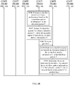
- a possible header structure that is of the IFIT information and that is used in an MPLS protocol network is shown in FIG. 1 , and key fields in the IFIT header structure are described herein.
- a head node in a detection domain encapsulates IFIT information (namely, in-situ flow metrics information) in the packet to indicate a network node in the detection domain to perform IFIT detection.
- a type of the packet may be, for example, a data packet or a control packet.
- a plurality of data packets or control packets may be continuously sent, for example, a plurality of data packets may constitute one data stream; or a plurality of data packets or control packets such as operations administration and maintenance (English: Operation, Administration and Maintenance, OAM for short) control packets are sent at intervals in a specific period.
- a network range in which IFIT detection needs to be performed may be determined by specifying a detection domain.
- a network node in the detection domain needs to transmit IFIT information to implement IFIT detection, and sends corresponding information obtained after the IFIT detection to a network management device.
- a detection range of the detection domain may be determined based on a plurality of manners, for example, may be determined based on a network scenario, where for example, a core network part in the network is specified as the detection domain; or may be determined based on a service type, where for example, detection domains of different ranges are specified for a video service and a voice service.
- An IFIT network includes three types of nodes, which are specifically a head node (English: head node), an end node (English: end node), and hops of path nodes (English: path node).
- the hops of path nodes may also be referred to as intermediate nodes.
- the head node, the end node, and the path node may be, for example, corresponding network nodes in the network.
- the first network node transmitting the data stream within a specified detection range of the detection domain may be used as a head node for transmitting the data stream.
- the last network node transmitting the data stream within the specified detection range of the detection domain may be used as an end node for transmitting the data stream.
- Nodes transmitting the data stream between the head node and the end node are hops of path nodes.
- the IFIT information may be added by the head node and peeled off by the end node.
- the detection domain in this application is a network domain to which in-situ flow metrics are applied.
- the detection domain includes a plurality of forwarding devices, for example, a router or a switch, for which an in-situ flow metrics function is enabled.
- the detection domain may further include a control management device such as a logical centralized controller, configured to: perform in-situ flow metrics configuration on the plurality of forwarding devices in the detection domain, and collect and analyze in-situ flow metrics data reported by the plurality of forwarding devices.
- Active in-situ flow metrics mean that based on the in-situ flow metrics technology described above, when a head node in a detection domain does not receive real service traffic sent by user equipment, the head node actively generates detection traffic, and encapsulates in-situ flow metrics information in the detection traffic. For example, if IFIT in-situ flow metrics are used as a basis, a detection packet carries IFIT in-situ flow metrics information. The head node sends the detection packet to an end node along a forwarding path of the detection packet, and a node in the forwarding path in the detection domain may measure network performance based on the received detection packet.
- active in-situ flow metrics are an extension of conventional passive in-situ flow metrics, so that an in-situ flow metrics protocol supports an active metrics capability, thereby implementing high-precision detection of network performance when there is no real service traffic.
- whether the forwarding path meets a service bearer requirement may be determined based on a measurement result of the active in-situ flow metrics. Therefore, a scenario in which there is real service traffic and a scenario lacking real service traffic can be covered based on a same in-situ flow metrics protocol.
- FIG. 2 is a schematic diagram of a network architecture according to an embodiment of this application.
- a network 100 includes a control management device and a plurality of network nodes.
- the plurality of network nodes are connected by using a communications link and are configured to transmit a data stream.
- a head node, an intermediate node 1, an intermediate node 2, and an end node in a detection domain are connected by using a communications link.
- the detection domain may include other nodes not shown.
- the end node may also be connected to an external node by using a communications link.
- a data stream sent by user equipment may pass through the head node, the intermediate node 1, the intermediate node 2, and the end node along a forwarding path 1, to reach the external node.
- the control management device may be, for example, a centralized controller, a network management center, or a traffic analysis device that performs a traffic analysis function.
- the control management device may be one device, or may be a set of a plurality of devices.
- the control management device may be configured to perform information collection and transmission path performance detection on a data packet in a transmission path between the plurality of network nodes.
- the transmission path performance detection includes but is not limited to detection of a transmission delay, a packet loss rate, and a packet loss location.
- the transmission path may include a path through which a data stream passes.
- the control management device may determine a detection domain.
- the detection domain is a detection range determined by the control management device.
- each forwarding device in a detection domain may perform configuration to obtain the detection domain.
- network nodes located between a head node and an end node in the detection domain are intermediate nodes, for example, the intermediate node 1 and the intermediate node 2 in FIG. 2 .
- FIG. 3 is a schematic diagram of another network architecture according to this application.
- a network 200 shown in FIG. 3 mainly differs from the network 100 shown in FIG. 2 in that a plurality of transmission paths exist between a head node and an end node.
- the plurality of transmission paths include at least a forwarding path 1 and a forwarding path 2 shown in FIG. 3 .
- a data stream sent by user equipment may pass through the head node, an intermediate node 1, an intermediate node 2, and the end node along the forwarding path 1, to reach an external node; or may pass through the head node, an intermediate node 3, an intermediate node 4, and the end node in a detection domain along the forwarding path 2, to reach an external node.
- the forwarding path 1 may be a working path, and the forwarding path 2 may be a protection path.
- the forwarding path 1 When the forwarding path 1 is faulty, the forwarding path 2 carries service traffic.
- the forwarding path 1 and the forwarding path 2 may be equivalent paths.
- the head node When receiving a service flow sent by the user equipment, the head node selects, through hash calculation, the forwarding path 1 to carry service traffic.
- FIG. 2 or FIG. 3 only shows, as examples, four nodes included in the detection domain, and the detection domain may include any other quantity of nodes. This is not limited in embodiments of this application.
- the network architecture shown in FIG. 2 or FIG. 3 is merely an example for description.
- An application scenario of in-situ flow metrics provided in this application is not limited to the scenario shown in FIG. 2 or FIG. 3 .
- the technical solution provided in this application is applicable to all network scenarios in which the in-situ flow metrics technology is used to perform data transmission.
- the forwarding path 2 when being used as a protection path, usually does not carry real service traffic, and it is expected to measure a performance indicator of the forwarding path 2 to determine whether the protection path meets a service bearer requirement, so that when a working path is faulty, traffic can be switched to a protection path that meets the service bearer requirement.
- performance detection cannot be completed based on a current in-situ flow metrics technology.
- protocol configuration is quite complicated.
- this application provides an active in-situ flow metrics method 100.
- An in-situ flow metrics protocol is extended to support an active metrics capability, so that in a network scenario in which there is no real service traffic, in-situ flow measurement can also be performed on network performance based on an in-situ flow metrics technology.
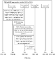
- FIG. 4A and FIG. 4B the following uses the scenario shown in FIG. 3 as an example to briefly describe the active in-situ flow metrics method 100 in this application.
- FIG. 4A and FIG. 4B show an active in-situ flow metrics method 100 according to an embodiment of this application.
- the method 100 may include, for example, the following S101 to S110.
- a head node in a detection domain generates a detection packet 1, where the detection packet 1 includes a packet header 1 and an analog service packet 1 generated by the head node, and the packet header 1 includes in-situ flow metrics information 1.
- any extended in-situ flow metrics protocol may be configured to support execution of S101 to S110 in the method 100.
- the in-situ flow metrics protocol may be, for example, any one of an IFIT protocol, an IOAM protocol, and an INT protocol.
- in-situ flow metrics performed by the head node, an intermediate node 1, an intermediate node 2, and an end node are consistent with the configured protocol.
- the in-situ flow metrics performed are any one of IFIT in-situ flow metrics, IOAM in-situ flow metrics, and INT in-situ flow metrics.
- a function module that can generate a detection packet is provided on the head node in the detection domain, and the function module may be referred to as a packet transmitter.
- the head node in the forwarding path 1 in the detection domain may generate the detection packet 1 to implement the active in-situ flow metrics method 100 to perform network performance measurement on nodes and links included in the forwarding path 1.
- a process in which the head node generates the detection packet 1 may specifically include: S11: The head node generates the analog service packet 1. S12: The head node encapsulates, in the analog service packet 1, the packet header 1 including the in-situ flow metrics information 1, to obtain the detection packet 1.
- the generated detection packet 1 varies with a network environment.
- the packet header 1 is adaptably encapsulated based on a packet type of the detection packet 1.
- the detection packet 1 is an IPv4 packet, and the packet header 1 may be encapsulated in an option OPTION field of the IPv4 packet.
- the detection packet 1 is an IPv6 packet, and the packet header 1 may be encapsulated in an IPv6 packet header (for example, a hop-by-hop (English: Hop By Hop) header).
- the detection packet 1 is an SRv6 packet
- the packet header 1 may be encapsulated in an SRv6 extension header (English: Segment Routing Header, SRH for short) of the SRv6 packet.
- the packet header 1 may be encapsulated in an MPLS packet header. It should be noted that a person skilled in the art may specifically encapsulate the packet header 1 in this embodiment of this application based on existing common knowledge, to generate a corresponding detection packet 1.
- the analog service packet 1 generated in S11 is not a real service packet sent by the user equipment to the head node, but an analog packet that is transmitted in the detection domain along the forwarding path 1 and that is generated by the head node to simulate a real service packet 1 that may be sent by the user equipment along the forwarding path 1.
- the packet header 1 in S12 is a packet header encapsulated, after the analog service packet 1 is generated, in the analog service packet 1 to generate the detection packet 1.
- the in-situ flow metrics information 1 in the packet header 1 is used to indicate each node in the forwarding path 1 to perform in-situ flow metrics on network performance.
- the in-situ flow metrics information 1 further includes indication information 1, and the indication information 1 is used to indicate the end node in the forwarding path 1 in the detection domain not to forward the detection packet 1 to another node.
- the end node uses the detection packet as a real service packet, and sends the packet to a node outside the detection domain, affecting a service provided for a user.
- the analog service packet 1 may be a layer-2 packet or a layer-3 packet. Whether the head node specifically generates a layer-2 analog service packet 1 or a layer-3 analog service packet 1 may depend on whether the real service packet 1 is a layer-2 packet or a layer-3 packet. Specifically, if the real service packet 1 transmitted by the head node along the forwarding path 1 is a layer-2 packet, the generated analog service packet 1 may be a layer-2 packet. If the real service packet 1 transmitted by the head node along the forwarding path 1 is a layer-3 packet, the generated analog service packet 1 may be a layer-3 packet.
- both the analog service packet 1 and the real service packet 1 are layer-2 packets, and the real service packet 1 carries a virtual local area network (English: Virtual Local Area Network, VLAN for short) identifier.
- the VLAN identifier is used to identify a VLAN to which the user equipment belongs, and the real service packet 1 may enter the head node from a port 1, in other words, the port 1 is an ingress port used by the head node to receive the real service packet 1.
- the analog service packet 1 generated by the head node by simulating the real service packet 1 may include the VLAN identifier, and may further include a port number corresponding to the port 1.
- the port number is used to indicate the port 1. In this way, it can be ensured that the detection packet 1 generated by the head node based on the analog service packet 1 is also transmitted in the detection domain along the forwarding path 1.
- a forwarding table included in each node includes a correspondence between an ingress port on the node, a VLAN identifier, and an egress port on the node, and a real service packet is forwarded based on a VLAN to which the real service packet belongs. Therefore, for the real service packet 1 carrying a VLAN identifier 1, after receiving the real service packet 1 from the ingress port 11, the head node parses out the VLAN identifier 1 carried in the real service packet 1 to determine an egress port 12 based on the ingress port 11 and the VLAN identifier 1, and forwards the real service packet 1 from the egress port 12 to a next-hop node (namely, the intermediate node 1).
- the head node needs to perform, through simulation, configuration that the analog service packet 1 is received from the ingress port 11 (namely, an ingress port of the real service packet 1). For example, the head node notifies, by using a configuration command, a forwarder responsible for packet forwarding that an ingress port of the analog service packet 1 is the port 11.
- the head node adds, to the analog service packet 1, a port number used to identify the ingress port 11, but needs to delete the port number from the analog service packet 1 before forwarding the analog service packet 1 to the next-hop node.
- the head node parses out the VLAN identifier 1 carried in the analog service packet 1 to determine the egress port 12 based on the ingress port 11 and the VLAN identifier 1, and forwards the analog service packet 1 from the egress port 12 to the next-hop node (namely, the intermediate node 1).
- the analog service packet 1 can be forwarded along the forwarding path 1 of the real service packet in the detection domain.
- a forwarding table included in each node includes a correspondence between an ingress port on the node, a VLAN identifier, a source media access control (English: Media Access Control Address, MAC for short) address (referred to as a destination MAC address below), and an egress port on the node, and a real service packet is forwarded based on a VLAN to which the real service packet belongs and a destination MAC address of the real service packet.
- MAC Media Access Control Address
- the head node parses out the VLAN identifier 1 and the destination MAC address 1 that are carried in the real service packet 1 to determine an egress port 12 based on the ingress port 11, the VLAN identifier 1, and the destination MAC address 1, and forwards the real service packet 1 from the egress port 12 to a next-hop node (namely, the intermediate node 1).
- the head node needs to perform, through simulation, configuration that the analog service packet 1 is received from the ingress port 11 (namely, an ingress port of the real service packet 1). For example, the head node notifies, by using a configuration command, a forwarder responsible for packet forwarding that an ingress port of the analog service packet 1 is the port 11.
- the head node adds, to the analog service packet 1, a port number used to identify the port 11, but needs to delete the port number from the analog service packet 1 before forwarding the analog service packet 1 to the next-hop node.
- the head node parses out the VLAN identifier 1 and the destination MAC address 1 that are carried in the analog service packet 1 to determine the egress port 12 based on the ingress port 11, the VLAN identifier 1, and the destination MAC address 1, and forwards the analog service packet 1 from the egress port 12 to the next-hop node (namely, the intermediate node 1).
- forwarding tables on all subsequent nodes are consistent, it is ensured that the analog service packet 1 can be forwarded along the forwarding path 1 of the real service packet in the detection domain.
- the detection packet 1 including the analog service packet 1 may further carry a source MAC address, a destination MAC address, a source Internet protocol (English: Internet Protocol, IP for short) address, and a destination IP address.
- the source MAC address may be a MAC address of a node other than nodes in the forwarding path 1 or a MAC address of an interface on a node other than nodes in the forwarding path 1.
- a destination MAC address of a private-line service may be a MAC address of a node other than the nodes in the forwarding path 1 or a MAC address of an interface on a node other than the nodes in the forwarding path 1.
- a destination MAC address of a dedicated-network service may be a destination MAC address of the real service packet 1.
- the source IP address and the destination IP address each may be any unicast IP address.
- the head node may further receive the real service packet 1 from the ingress port (namely, the port 1).
- the real service packet 1 carries the VLAN identifier or the real service packet 1 carries the VLAN identifier and a destination MAC address. Therefore, the head node may determine an egress port based on a forwarding table stored on the head node, and it is true for each hop of node, so that it is determined that the forwarding path 1 of the real service packet 1 in the detection domain sequentially includes the head node, the intermediate node 1, the intermediate node 2, and the end node, in other words, the head node forwards the real service packet 1 to the end node along the forwarding path 1.
- the in-situ flow metrics method can completely and truly measure network performance of a forwarding path for transmitting the real service packet in the detection domain.
- both the analog service packet 1 and the real service packet 1 are layer-3 packets.
- the real service packet 1 carries a source IP address and a destination IP address. It is known that in the detection domain, an IP address of an ingress interface 11 used by the head node to receive the real service packet 1 is an IP address 11, and an IP address of an egress interface 12 used by the end node to forward the real service packet 1 to a user side is an IP address 12. It is determined, based on the source IP address and the destination IP address, that a forwarding path of the real service packet 1 in the network includes the forwarding path 1 determined based on a network segment to which the IP address 11 belongs and a network segment to which the IP address 12 belongs.
- the generated analog service packet 1 may also include a source IP address 3 and a destination IP address 4.
- the source IP address 3 and the IP address 11 belong to a same network segment, and the destination IP address 4 and the IP address 12 belong to a same network segment. In this way, it can be ensured that the detection packet 1 generated by the head node based on the analog service packet 1 is also transmitted in the detection domain along the forwarding path 1.
- the head node may further receive the real service packet 1 from the ingress interface (namely, the ingress interface 1). In addition, the head node forwards the real service packet 1 to the end node along the forwarding path 1. If the end node is not a destination node of the real service packet 1, the end node forwards the real service packet 1 to another node from the egress interface 2 on the end node until the real service packet 1 is forwarded to a user-side device.
- the user-side device may be a device corresponding to the destination IP address of the real service packet 1. The device receives the real service packet 1 to provide a corresponding service for a user.
- the in-situ flow metrics method can completely and truly measure network performance of a forwarding path for transmitting the real service packet in the detection domain.
- the generated analog service packet 1 may carry the source IP address 3 and the destination IP address 4.
- the source IP address 3 may be any IP address that belongs to a same network segment as the IP address 11 of the ingress interface 11 used by the head node to receive the real service packet 1
- the destination IP address 4 may be any IP address that belongs to a same network segment as the IP address 12 of the egress interface 12 used by the end node to send the real service packet 1.
- the detection packet 1 including the analog service packet 1 may further carry a source MAC address and a destination MAC address.
- the source MAC address may be any unicast MAC address other than a MAC address corresponding to the ingress interface 1 on the head node, and the destination MAC address may be the MAC address corresponding to the ingress interface 1 on the head node. It should be noted that before the detection packet 1 is forwarded from the head node to the intermediate node 1, the source MAC address needs to be replaced with a MAC address corresponding to an egress interface on the head node, and the destination MAC address needs to be replaced with a MAC address corresponding to an ingress interface on the intermediate node 1, to support normal forwarding of the layer-3 packet.
- the generated detection packet 1 may be specifically an IPv4 or IPv6 packet.
- the detection packet 1 needs to be forwarded in the detection domain, and cannot be forwarded from the end node of the forwarding path 1 to another node outside the detection domain.
- the in-situ flow metrics information 1 not only indicates each node receiving the detection packet 1 to perform in-situ flow metrics, but also carries the indication information 1 to indicate the end node of the forwarding path 1 in the detection domain not to forward the detection packet 1 to another node.
- the indication information 1 may specifically correspond to different content based on different network environments.
- the indication information 1 may be, for example, obtained by extending a reserved field in an in-situ flow metrics header 1 of the packet header 1, for example, adding at least one bit, where information indicated by the at least one bit is the indication information 1.
- an identifier may be added to another field in an in-situ flow metrics header 1 of the packet header 1 to indicate the indication information 1.
- the indication information 1 may be type information obtained after an in-situ flow metrics header 1 of the packet header 1 is extended.
- the indication information 1 may be one or more bits. This is not specifically limited in this application. The following describes some specific implementations of the indication information 1 by using examples.
- the packet header 1 may be the in-situ flow metrics header 1, and the indication information 1 may be a value of a preset field or a flag bit carried in the in-situ flow metrics header 1.
- the indication information 1 may be information indicated by at least one bit included in the in-situ flow metrics header 1. IFIT detection is used as an example.
- the in-situ flow metrics header 1 may be a flow instruction header FIH field in FIG. 1
- the indication information 1 may be, for example, a value of a flag bit R in the FIH. For example, when the value of the flag bit R is 0, it may indicate that the detection packet 1 is passive in-situ flow metrics.
- the indication information 1 may be a value of a preset field in the in-situ flow metrics header 1. IFIT detection is still used as an example. Referring to FIG. 1 , the indication information 1 may be specifically information indicated by a header type indicator HTI, and a value of the HIT can indicate whether the in-situ flow metrics header 1 includes a flow instruction extension header FIEH field or a type of an FIEH.
- the detection packet 1 is passive in-situ flow metrics.
- the value of the HIT indicates that the in-situ flow metrics header 1 does not include an FIEH or includes an FIEH whose type is passive in-situ flow metrics, it is determined that the detection packet 1 is passive in-situ flow metrics.
- the value of the HIT indicates that the in-situ flow metrics header 1 includes an FIEH whose type is active in-situ flow metrics, it is determined that the detection packet 1 is active in-situ flow metrics.
- the packet header 1 includes an extended in-situ flow metrics header 1, and the indication information 1 may be carried in the extended in-situ flow metrics header 1, and may be specifically information indicated by a type field of the extended in-situ flow metrics header 1. IFIT detection is used as an example.
- the extended in-situ flow metrics header 1 may be an FIEH shown in FIG. 1 .
- the indication information 1 may be, for example, a value of a type field of the FIEH, and the value of the type field of the FIEH is used to indicate that the in-situ flow metrics are active in-situ flow metrics or passive in-situ flow metrics.
- the indication information 1 may be a value of any preset field or flag bit that may be used as an indication in the FIEH.
- the packet header 1 includes an option OPTION field, and the OPTION field may carry the indication information 1.
- the indication information 1 may be specifically information indicated by a type field of the OPTION field or information indicated by at least one bit included in the OPTION field. IFIT is used as an example.
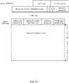
- FIG. 5a shows a format of an extended OPTION field in the detection packet 1.
- the indication information 1 may be specifically information indicated by a type Type field of the extended OPTION field, or the indication information 1 may be values of one or more bits of a reserved Reserved field or another field.
- IOAM detection is used as an example.
- FIG. 5b shows a format of an extended OPTION field in the detection packet 1.
- the indication information 1 may be specifically information indicated by an IOAM Type field of the extended OPTION field, or the indication information 1 may be values of one or more bits of IOAM data Data.
- a packet header 1 of IOAM may be specifically encapsulated in an IPv6 packet header, a virtual extensible local area network (English: Virtual Extensible Local Area Network, VXLAN for short) packet header, or an IPv4 packet header.
- a packet header 1 of IOAM may be alternatively encapsulated in an SRH.
- the head node in the detection domain may measure network performance based on the in-situ flow metrics information 1 in the detection packet 1 to obtain a measurement result 0.
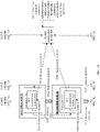
- the head node 10 in a network architecture in an embodiment shown in FIG. 7A , FIG. 7B , and FIG. 7C .
- the head node 10 includes a forwarder 102, and the forwarder 102 includes a measurement module 1021 configured to implement in-situ flow metrics.
- a process in which the head node measures the network performance based on the in-situ flow metrics information 1 in the detection packet 1 may include: S21: The head node 10 transmits the detection packet 1 generated by the packet transmitter 101 to the forwarder 102.
- the forwarder 102 identifies that the received detection packet 1 is an active in-situ flow metrics packet, and the measurement module 1021 measures the network performance based on the in-situ flow metrics information 1 in the detection packet 1 to obtain the measurement result 0.
- the measurement result 0 may include, for example, a packet count and a timestamp, and is used to reflect network performance of the head node 10 and a link connected to the head node 10.
- the in-situ flow metrics information 1 can indicate whether the in-situ flow metrics are active in-situ flow metrics or passive in-situ flow metrics, and further include identification information 2 that can indicate whether the in-situ flow metrics are edge-to-edge (English: Edge to Edge, E2E for short) in-situ flow metrics or hop-by-hop in-situ flow metrics.
- the identification information 2 may be the indication information 1, in other words, the indication information 1 can indicate whether the detection packet 1 is E2E active in-situ flow metrics or hop-by-hop active in-situ flow metrics. In this case, referring to the MPLS network environment shown in FIG.
- the indication information 1 may be, for example, information indicated by an HTI field.
- a definition of an extended HTI type may be added.
- the identification information 2 may be information other than the indication information 1, and is used to separately identify whether the detection packet 1 uses an E2E or a hop-by-hop detection mechanism.
- each node in the forwarding path 1 is required to send an obtained measurement result to a control management device after performing network performance measurement.
- each node in the forwarding path 1 is required to add an obtained measurement result to a detection packet and send the measurement result to a next hop, until the end node obtains a corresponding measurement result and then sends, to the control management device, the measurement result of the end node and a measurement result that is carried in the detection packet and that corresponds to each hop of node.
- the head node when identifying that the generated detection packet 1 corresponds to hop-by-hop active in-situ flow metrics, the head node needs to send the obtained measurement result 0 to the control management device and perform S102. When identifying that the generated detection packet 1 corresponds to E2E active in-situ flow metrics, the head node may add the obtained measurement result 0 to the detection packet 1 to obtain the detection packet 1 in S102, to continue to perform the method 100.
- the head node sends the detection packet 1 to the intermediate node 1 along the forwarding path 1.
- the head node may measure the network performance based on the in-situ flow metrics information 1 in the detection packet 1 to obtain the measurement result 0.
- the head node may further send the detection packet 1 to the intermediate node 1 along the forwarding path 1, so that the intermediate node 1 measures network performance based on the in-situ flow metrics information 1 in the detection packet 1.
- the head node 10 determines, based on the determined forwarding path 1, that a next hop is an intermediate node 11.
- the forwarder 102 of the head node may forward the detection packet 1 to a forwarder 112 of the intermediate node 11.
- the intermediate node 1 performs in-situ flow metrics on the network performance based on the in-situ flow metrics information 1 in the detection packet 1.
- the intermediate node 1 may measure the network performance based on the in-situ flow metrics information 1 in the detection packet 1 to obtain a measurement result 1.
- the intermediate node 1 refers to the intermediate node 11 in the network architecture in the embodiment shown in FIG. 7A , FIG. 7B , and FIG. 7C .
- the intermediate node 11 includes the forwarder 112, and the forwarder 112 includes a measurement module 1121 configured to implement in-situ flow metrics.
- a process in which the intermediate node measures the network performance based on the in-situ flow metrics information 1 in the detection packet 1 may include: S31: The intermediate node 11 transmits the received detection packet 1 to the forwarder 112.
- the forwarder 112 identifies that the received detection packet 1 is an active in-situ flow metrics packet, and the measurement module 1121 measures the network performance based on the in-situ flow metrics information 1 in the detection packet 1 to obtain the measurement result 1.
- the measurement result 1 is used to reflect network performance of the intermediate node 11 and a link connected to the intermediate node 11.
- the intermediate node 1 updates the detection packet 1 to obtain a detection packet 1', where the detection packet 1' includes in-situ flow metrics information 1'.
- the intermediate node 1 When identifying that the received detection packet 1 corresponds to hop-by-hop active in-situ flow metrics, the intermediate node 1 needs to send the obtained measurement result 1 to the control management device; or when identifying that the received detection packet 1 corresponds to E2E active in-situ flow metrics, the intermediate node 1 may add the obtained measurement result 1 to the detection packet 1.
- the intermediate node 1 identifies that the intermediate node 1 is not the end node of the forwarding path 1 in the detection domain, and updates the detection packet 1 to the detection packet 1'.
- the detection packet 1' includes the in-situ flow metrics information 1', and the in-situ flow metrics information 1' still includes the indication information 1.
- the detection packet 1' when the in-situ flow metrics are E2E active in-situ flow metrics, the detection packet 1' further includes the measurement result 0 and the measurement result 1; or when the in-situ flow metrics are hop-by-hop active in-situ flow metrics, the detection packet 1' may not include the measurement result 0 or the measurement result 1.
- the intermediate node 1 sends the detection packet 1' to the intermediate node 2 along the forwarding path 1.
- the intermediate node 2 performs in-situ flow metrics on network performance based on the in-situ flow metrics information 1' in the detection packet 1'.
- the intermediate node 2 updates the detection packet 1' to obtain a detection packet 1", where the detection packet 1" includes in-situ flow metrics information 1".
- the intermediate node 2 sends the detection packet 1" to the end node in the detection domain along the forwarding path 1.
- the intermediate node 2 may measure the network performance based on the in-situ flow metrics information 1' in the detection packet 1' to obtain a measurement result 2.
- S109 The end node performs in-situ flow metrics on network performance based on the in-situ flow metrics information 1" in the detection packet 1".
- the end node may measure the network performance based on the in-situ flow metrics information 1" in the detection packet 1" to obtain a measurement result 3.
- the end node 13 in the network architecture in the embodiment shown in FIG. 7A , FIG. 7B , and FIG. 7C .
- the end node 13 includes a packet receiver 131 configured to collect a detection packet
- the forwarder 132 includes a measurement module 1321 configured to implement in-situ flow metrics.
- a process in which the end node measures the network performance based on the in-situ flow metrics information 1" in the detection packet 1" may include: S41: The end node 13 transmits the received detection packet 1" to the forwarder 132.
- the forwarder 132 identifies that the received detection packet 1" is an active in-situ flow metrics packet, and the measurement module 1321 measures the network performance based on the in-situ flow metrics information 1" in the detection packet 1" to obtain the measurement result 3.
- the end node determines, based on the indication information 1 included in the in-situ flow metrics information 1" in the detection packet 1", not to forward the detection packet 1" to another node.
- the in-situ flow metrics information 1" of the detection packet 1" carries the indication information 1 to indicate the end node in the detection domain not to forward the detection packet 1" to another node.
- S43 The end node 13 parses the detection packet 1" to obtain the indication information 1, and determines that the end node 13 is the end node of the forwarding path 1 in the detection domain, and the end node 13 may terminate the detection packet 1" to prevent traffic from being sent to a network outside the detection domain.
- the end node 13 may terminate the detection packet 1" in the following implementation: The end node 13 directly deletes the detection packet 1". Alternatively, the end node may terminate the detection packet 1" in the following implementation: The forwarder 132 of the end node 13 may send the detection packet 1" to the packet receiver 131, and the packet receiver 131 stores or deletes the detection packet 1". Because the packet receiver 131 is a module in the end node 13 and does not have an interface for communicating with another node, the end node 13 can also be prevented from forwarding the detection packet 1" to another node.
- the method provided in this embodiment of this application is equivalent to providing a new in-situ flow metrics mechanism, and only one extended in-situ flow metrics protocol needs to be configured to complete both active in-situ flow metrics and passive in-situ flow metrics, so that various scenarios of network performance detection can be covered, thereby facilitating network performance detection.
- a detection packet generated by the head node when an active in-situ flow metrics technology is used, a detection packet generated by the head node further needs to carry indication information to notify the end node that the end node receives a detection packet exclusively used for network performance measurement and indicate the end node not to forward the detection packet to another node.
- the detection packet that is not a real service packet and that is exclusively used for measurement is terminated by the end node, and is not forwarded by the end node to a node outside the detection domain, so that a real service provided for the user is prevented from being affected, thereby making the network performance detection mechanism more intelligent.
- the real service packet can be transmitted by using the forwarding path 1.
- the head node determines, when receiving the real service packet 1, that a forwarding path of the real service packet 1 is the forwarding path 1, the head node forwards the real service packet 1 out of the detection domain by using the intermediate node 1, the intermediate node 2, and the end node, and the end node forwards the real service packet 1 to another node outside the detection domain until the real service packet 1 is transmitted to a destination node of the real service packet 1.
- the head node may generate different detection packets based on different to-be-detected forwarding paths, and separately perform network performance measurement on the different to-be-detected forwarding paths. Measurement processes of the two are basically the same and independent of each other.
- this application further provides an active in-situ flow metrics method 200.
- the method 200 may include S201 to S210 used to measure a forwarding path 2.
- the head node in the detection domain generates a detection packet 2, where the detection packet 2 includes a packet header 2 and an analog service packet 2 generated by the head node, and the packet header 2 includes in-situ flow metrics information 2.
- the analog service packet 2 is not a real service packet sent by the user equipment.
- the forwarding path 2 that is of the detection packet 2 in the detection domain and that is determined based on the analog service packet 2 is used to simulate a forwarding path, in the detection domain, of a real service packet 2 sent by the user equipment.
- the packet header 2 includes the in-situ flow metrics information 2, the in-situ flow metrics information 2 is used by a node in the forwarding path 2 to perform in-situ flow metrics on network performance, the in-situ flow metrics information 2 includes indication information 2, and the indication information 2 is used to indicate the end node in the detection domain not to forward the detection packet 2 to another node.
- the analog service packet 2 and the analog service packet 1 are different in at least one of a protocol number, a transmission control protocol (English: Transmission Control Protocol, TCP for short) port number, and a user datagram protocol (English: User Datagram Protocol, UDP for short) port number.
- a protocol number a transmission control protocol
- a user datagram protocol English: User Datagram Protocol, UDP for short
- it is determined to test network performance for different forwarding paths after the head node generates the two detection packets. For example, if the analog service packet 2 and the analog service packet 1 have different protocol numbers, the head node separately determines different forwarding paths of the analog service packet 1 and the analog service packet 2 in the detection domain based on the different protocol numbers.
- the head node separately determines different forwarding paths of the analog service packet 1 and the analog service packet 2 in the detection domain based on the different TCP port numbers (or UDP port numbers). For still another example, if the analog service packet 2 and the analog service packet 1 have different protocol numbers and carry different TCP port numbers (or UDP port numbers), the head node separately determines different forwarding paths of the analog service packet 1 and the analog service packet 2 in the detection domain based on the different protocol numbers and TCP port numbers (or UDP port numbers).
- S202 The head node sends the detection packet 2 to an intermediate node 3 along the forwarding path 2.
- S203 The intermediate node 3 performs in-situ flow metrics on network performance based on the in-situ flow metrics information 2 in the detection packet 2.
- the intermediate node 3 updates the detection packet 2 to obtain a detection packet 2', where the detection packet 2' includes in-situ flow metrics information 2'.
- S205 The intermediate node 3 sends the detection packet 2' to an intermediate node 4 along the forwarding path 2.
- the intermediate node 4 performs in-situ flow metrics on network performance based on the in-situ flow metrics information 2' in the detection packet 2'.
- the intermediate node 4 updates the detection packet 2' to obtain a detection packet 2", where the detection packet 2" includes in-situ flow metrics information 2".
- the intermediate node 4 sends the detection packet 2" to the end node in the detection domain along the forwarding path 2.
- S209 The end node performs in-situ flow metrics on network performance based on the in-situ flow metrics information 2" in the detection packet 2".
- S210 The end node determines, based on the indication information 2 included in the in-situ flow metrics information 2" in the detection packet 2", not to forward the detection packet 2" to another node.
- the detection packet carries indication information
- the detection packet that is not a real service packet and that is exclusively used for measurement is terminated by the end node, and is not forwarded by the end node to a node outside the detection domain, so that a real service provided for the user is prevented from being affected, thereby making the network performance detection mechanism more intelligent.
- a plurality of forwarding paths with a same head node and a same end node in the detection domain can be detected, so that the network performance detection mechanism can adapt to more network scenarios, thereby implementing more complete network performance measurement in the detection domain.
- a real service packet can be transmitted by using the forwarding path 1 and the forwarding path 2.
- the head node may determine a forwarding path of the real service packet 2 based on at least one of a protocol number, a TCP port number, and a UDP port number carried in the real service packet 2, and transmit the real service packet 2 along the determined forwarding path.
- the head node determines that the protocol number and/or the TCP port number and/or the UDP port number carried in the real service packet 2 are or is correspondingly the same as a protocol number and/or a TCP port number and/or a UDP port number carried in the detection packet 1, the head node determines that the forwarding path of the real service packet 2 is the forwarding path 1, and forwards the real service packet 2 out of the detection domain by using the intermediate node 1, the intermediate node 2, and the end node.
- the head node determines that at least one of the protocol number, the TCP port number, and the UDP port number carried in the real service packet 2 is correspondingly the same as at least one of a protocol number, a TCP port number, and a UDP port number that are carried in the detection packet 2, the head node determines that the forwarding path of the real service packet 2 is the forwarding path 2, and forwards the real service packet 2 out of the detection domain by using the intermediate node 3, the intermediate node 4, and the end node.
- the following uses IFIT as an example to describe internal structures (only a part used in an implementation process of embodiments of this application is considered) of nodes in a detection domain and an active in-situ flow metrics process in the network scenario 100.
- the network includes a control management device 100, a head node 10, an intermediate node 11, an intermediate node 12, and an end node 13.
- the head node 10 includes an IFIT packet transmitter 101 configured to generate a detection packet and a forwarder 102, and the forwarder 102 includes an IFIT measurement module 1021.
- the intermediate node 11 includes a forwarder 112, and the forwarder 112 includes an IFIT measurement module 1121.
- the intermediate node 12 includes a forwarder 122, and the forwarder 122 includes an IFIT measurement module 1221.
- the end node 13 includes an IFIT packet receiver 131 configured to terminate a detection packet and a forwarder 132, and the forwarder 132 includes an IFIT measurement module 1321.
- the control management device 100 is configured to: collect measurement results of nodes in a detection domain, and perform analysis and management.
- an extended IFIT protocol provided in embodiments of this application is configured. If there is real service traffic in a forwarding path X: head node 10->intermediate node 11->intermediate node 12->end node 13, network performance measurement is performed on nodes and links in the forwarding path X in the detection domain according to a current IFIT passive in-situ flow metrics mechanism. Details are not described herein.
- network performance measurement may be performed on the nodes and the links in the forwarding path X in the detection domain according to S301 to S312.
- the IFIT packet transmitter 101 of the head node 10 generates a detection packet a, and sends the detection packet to the forwarder 102, where the detection packet a includes a packet header a and an analog service packet a, the packet header a includes an in-situ flow metrics header a, the in-situ flow metrics header a includes indication information 1, and the instruction information 1 is used to indicate that detection of the detection packet a is hop-by-hop active in-situ flow metrics and indicate the end node 13 not to forward the detection packet a to another node.
- the forwarder 102 of the head node 10 identifies that detection of the detection packet a is hop-by-hop active in-situ flow metrics, and the IFIT measurement module 1021 of the forwarder 102 performs network performance measurement based on the in-situ flow metrics header a to obtain a measurement result 10, and sends the measurement result 10 to the control management device 100.
- the forwarder 102 of the head node 10 updates the detection packet a to obtain a detection packet a', and sends the detection packet a' to the intermediate node 11, where the detection packet a' includes an in-situ flow metrics header a'.
- the IFIT measurement module 1121 of the forwarder 112 of the intermediate node 11 performs network performance measurement based on the in-situ flow metrics header a' to obtain a measurement result 11, and sends the measurement result 11 to the control management device 100.
- the forwarder 112 of the intermediate node 11 updates the detection packet a' to obtain a detection packet a", and sends the detection packet a" to the intermediate node 12, where the detection packet a" includes an in-situ flow metrics header a".
- the IFIT measurement module 1221 of the forwarder 122 of the intermediate node 12 performs network performance measurement based on the in-situ flow metrics header a" to obtain a measurement result 12, and sends the measurement result 12 to the control management device 100.
- the forwarder 122 of the intermediate node 12 updates the detection packet a" to obtain a detection packet a′′′, and sends the detection packet a′′′ to the intermediate node 12, where the detection packet a′′′ includes an in-situ flow metrics header a′′′.
- the IFIT measurement module 1321 of the forwarder 132 of the end node 13 performs network performance measurement based on the in-situ flow metrics header a′′′ to obtain a measurement result 13, and sends the measurement result 13 to the control management device 100.
- the end node 13 determines, according to the indication information 1 included in the in-situ flow metrics header a′′′ in the detection packet a′′′, not to forward the detection packet a′′′ to another node, and sends the detection packet a′′′ to the IFIT packet receiver 131 of the end node 13.
- the control management device 100 determines a performance indicator of the forwarding path X through analysis based on the received measurement results 10 to 13, evaluates whether the performance indicator meets a service bearer requirement, and if the performance indicator meets the service bearer requirement, determines that the forwarding path X passes the test.
- this embodiment may further include the following steps:
- the head node 10 receives a real service packet b, where the real service packet b and the detection packet a carry a same protocol number and a same TCP/UDP port number.
- the head node 10 determines that a transmission path passes through the forwarding path X, and forwards the real service packet b along the forwarding path X by using the intermediate node 11, the intermediate node 12, and the end node 13, and the end node 13 sends the real service packet b to another node until the real service packet b is transmitted to a destination node of the real service packet b, to provide a high-quality service for a user.
- hop-by-hop active in-situ flow metrics in a case of IFIT are used as an example for description.
- An implementation of active in-situ flow metrics in a case of another protocol (for example, IOAM) and detection mechanism (for example, E2E) is similar to the foregoing implementation.
- IOAM a measurement module included in each node is an IOAM measurement module
- the packet transmitter of the head node is an IOAM packet transmitter
- the packet receiver of the end node is an IOAM packet receiver
- a detection packet carries in-situ flow metrics information corresponding to IOAM
- a detection process is basically consistent. Details are not described one by one.
- FIG. 8 is a schematic flowchart of an active in-situ flow metrics method 400 according to an embodiment of this application.
- the method 400 is applied to a detection domain of in-situ flow metrics, and is performed by a head node, namely, a first network node, in the detection domain.
- the active in-situ flow metrics method 400 may include, for example, the following steps:
- the first network node generates a first detection packet, where the first network node is the head node in the detection domain; and the first detection packet includes a first packet header and a first analog service packet generated by the first network node, the first analog service packet is not a real service packet sent by user equipment, a first forwarding path that is of the first detection packet in the detection domain and that is determined based on the first analog service packet is used to simulate a forwarding path, in the detection domain, of a first real service packet sent by the user equipment, the first packet header includes first in-situ flow metrics information, the first in-situ flow metrics information is used by a node in the first forwarding path to perform in-situ flow metrics on network performance, the first in-situ flow metrics information includes first indication information, and the first indication information is used to instruct an end node in the detection domain not to forward the first detection packet to another node.
- the first network node sends the first detection packet to the end node in the detection domain along the first forwarding path.
- the first network node may be the head node in FIG. 2 or FIG. 3 or the head node 10 in FIG. 7A , FIG. 7B , and FIG. 7C .
- the first detection packet may be the detection packet 1 in the method 100 and the method 200.
- the first analog service packet may be the analog service packet 1 in the method 100 and the method 200
- the first packet header may be the packet header 1 in the method 100 and the method 200
- the first indication information may be the indication information 1 in the method 100 and the method 200
- the first forwarding path may be the forwarding path 1 in the method 100 and the method 200.
- the first detection packet may be the detection packet a in the method shown in FIG. 7A , FIG. 7B , and FIG. 7C
- the first analog service packet may be the analog service packet a in the method shown in FIG. 7A , FIG. 7B , and FIG. 7C
- the first packet header may be the packet header a in the method shown in FIG. 7A , FIG.
- the first indication information may be the indication information a in the method shown in FIG. 7A , FIG. 7B , and FIG. 7C
- the first forwarding path may be the forwarding path X in the method shown in FIG. 7A , FIG. 7B , and FIG. 7C .
- the first packet header may include a first in-situ flow metrics header, and the first in-situ flow metrics header includes the first indication information.
- the first indication information is information indicated by at least one bit included in the first in-situ flow metrics header.
- the first packet header may include a first extended in-situ flow metrics header, the first extended in-situ flow metrics header is used to carry the first indication information, and a type field of the first extended in-situ flow metrics header indicates that the in-situ flow metrics are active in-situ flow metrics.
- the first packet header may include an option OPTION field, and the OPTION field includes the first indication information.
- the first indication information is information indicated by at least one bit included in the OPTION field.
- the first indication information is information indicated by a type field of the OPTION field, and the type field indicates that the in-situ flow metrics are active in-situ flow metrics.
- the three examples are merely example descriptions of adding the first indication information to the first detection packet in this embodiment of this application.
- the foregoing three possible implementations are included but do not constitute a limitation. Any other information that can be used to indicate that the in-situ flow metrics are active in-situ flow metrics may be used as the first indication information in this embodiment of this application, and any packet header that can carry the first indication information may be used as the first packet header in this embodiment of this application.
- the in-situ flow metrics may be IFIT in-situ flow metrics, IOAM in-situ flow metrics, or INT in-situ flow metrics. Any in-situ flow metrics protocol may be extended by using the method provided in this embodiment of this application to support the active in-situ flow metrics method provided in this embodiment of this application.
- the in-situ flow metrics may be edge-to-edge E2E active in-situ flow metrics, or may be hop-by-hop active in-situ flow metrics. Details may be flexibly set based on an in-situ flow metrics requirement.
- a specific process in which the first network node generates the first detection packet in S401 may include: The first network node generates the first analog service packet. The first network node encapsulates the first in-situ flow metrics information in the first analog service packet. For a specific process, refer to related descriptions of S11 and S12 in the method 100.
- the first analog service packet may be a layer-2 packet
- the layer-2 packet includes a virtual local area network VLAN identifier
- the VLAN identifier is used to identify a VLAN to which the user equipment belongs.
- the method 400 may further include: The first network node receives the first real service packet.
- the first real service packet carries a same VLAN identifier as the first analog service packet.
- the first network node forwards the first real service packet to the end node along the first forwarding path.
- the layer-2 analog service packet generated by the head node carries a VLAN identifier carried in the real service packet, and simulates the layer-2 real service packet to enter an ingress port on the head node, so that the analog service packet is transmitted in the detection domain along a same forwarding path as the real service packet, and therefore a measurement result of network performance measurement is of real reference significance to forwarding of the real service packet in the detection domain.
- the layer-2 analog service packet generated by the head node carries a VLAN identifier and a destination MAC address that are carried in the real service packet, and simulates the layer-2 real service packet to enter an ingress port on the head node, so that the analog service packet is transmitted in the detection domain along a same forwarding path as the real service packet, and therefore a measurement result of network performance measurement is of real reference significance to forwarding of the real service packet in the detection domain.
- the first analog service packet may be a layer-3 packet
- the layer-3 packet includes a source Internet protocol IP address and a destination IP address
- the source IP address is an IP address that belongs to a same network segment as an IP address of an ingress interface used by the first network node to receive the first real service packet
- the destination IP address is an IP address that belongs to a same network segment as an IP address of an egress interface used by the end node to forward the first real service packet to a user side.
- the method 400 may further include: The first network node receives the first real service packet by using the ingress interface. The first network node forwards the first real service packet to the end node along the first forwarding path.
- a layer-3 packet is forwarded under guidance of a source IP address and a destination IP address, and forwarding paths of packets with source IP addresses in a same network segment and destination IP addresses in a same network segment are consistent, because network segments to which the source IP address and the destination IP address that are carried in the layer-3 analog service packet generated by the head node belong are correspondingly the same as network segments to which a source IP address and a destination IP address that are carried in the real service packet belong, the analog service packet is transmitted in the detection domain along a same forwarding path as the real service packet, so that a measurement result of network performance measurement is of real reference significance to forwarding of the real service packet in the detection domain.
- the method 400 further includes: The first network node generates a second detection packet.
- the first detection packet and the second detection packet have different protocol numbers and/or transmission control protocol TCP/user datagram protocol UDP port numbers.
- the second detection packet includes a second packet header and a second analog service packet generated by the first network node, a second forwarding path that is of the second detection packet in the detection domain and that is determined based on the second analog service packet is used to simulate a forwarding path, in the detection domain, of a second real service packet sent by the user equipment, the second packet header includes second in-situ flow metrics information, the second in-situ flow metrics information is used by a node in the second forwarding path to perform in-situ flow metrics on network performance, the second in-situ flow metrics information includes second indication information, and the second indication information is used to indicate the end node not to forward the second detection packet to another node.
- the first network node forwards the second detection packet to the end node along the second forwarding path.
- the method 400 may further include: The first network node receives the second real service packet sent by the user equipment.
- the second real service packet and the second detection packet carry a same protocol number and a same TCP/UDP port number.
- the first network node forwards the second real service packet to the end node along the second forwarding path.
- the second detection packet may be the detection packet 2 in the method 200.
- the second analog service packet may be the analog service packet 2 in the method 200
- the second packet header may be the packet header 2 in the method 200
- the second indication information may be the indication information 2 in the method 200
- the second forwarding path may be the forwarding path 2 in the method 200.
- a plurality of forwarding paths with a same head node and a same end node in the detection domain can be detected to provide data support for normal transmission, in a network, of different real service packets that need to be transmitted along different forwarding paths, so that the network performance detection mechanism can adapt to more network scenarios, thereby implementing more complete network performance measurement in the detection domain.
- FIG. 9 is a schematic flowchart of another active in-situ flow metrics method 500 according to an embodiment of this application.
- the method 500 is applied to a detection domain of in-situ flow metrics, and is performed by any node, namely, a second network node, after a head node in the detection domain.
- the active in-situ flow metrics method 500 may include, for example, the following steps:
- the second network node in the detection domain receives, by using a first forwarding path in the detection domain, a first detection packet sent by a first network node in the detection domain, where the first detection packet includes a first packet header and a first analog service packet, the first packet header includes first in-situ flow metrics information, the first in-situ flow metrics information includes indication information, the indication information is used to instruct an end node in the detection domain not to forward the first detection packet to another node, the first analog service packet is not a real service packet sent by user equipment, and the first forwarding path is used to simulate a forwarding path, in the detection domain, of a first real service packet sent by the user equipment.
- the second network node may be the end node in the detection domain, and after the second network node detects the network performance, the method 500 may further include: The second network node does not forward the first detection packet to another node according to the indication information.
- the second network node may be the end node in FIG. 2 or FIG. 3 or the end node 13 in FIG. 7A , FIG. 7B , and FIG. 7C .
- For a specific operation performed by the second network node refer to operations performed by the end node in the method 100 and the method 200, or refer to a corresponding operation performed by the end node 13 in FIG. 7A , FIG. 7B , and FIG. 7C .
- the first detection packet may be the detection packet 1" in the method 100 and the method 200.
- the first analog service packet may be the analog service packet 1" in the method 100 and the method 200
- the first packet header may be the packet header 1" in the method 100 and the method 200
- the indication information may be the indication information 1 in the method 100 and the method 200
- the first forwarding path may be the forwarding path 1 in the method 100 and the method 200.
- the first detection packet may be the detection packet 2" in the method 200.
- the first analog service packet may be the analog service packet 2" in the method 200
- the first packet header may be the packet header 2" in the method 200
- the indication information may be the indication information 2 in the method 200
- the first forwarding path may be the forwarding path 2 in the method 200.
- the first detection packet may be the detection packet a'" in the method shown in FIG. 7A , FIG. 7B , and FIG. 7C .
- the first analog service packet may be the analog service packet a'" in the method shown in FIG. 7A , FIG. 7B , and FIG. 7C
- the first packet header may be the packet header a'" in the method shown in FIG. 7A , FIG. 7B , and FIG. 7C
- the indication information may be the indication information a in the method shown in FIG. 7A , FIG. 7B , and FIG. 7C
- the first forwarding path may be the forwarding path X in the method shown in FIG. 7A , FIG. 7B , and FIG. 7C .
- the second network node may be an intermediate node in the detection domain, and the method 500 may further include: The second network node updates the first detection packet to obtain a second detection packet.
- the second detection packet includes second in-situ flow metrics information, and the second in-situ flow metrics information includes the indication information.
- the second network node forwards the second detection packet to the end node along the first forwarding path.
- the second network node may be the intermediate node 1 or the intermediate node 2 in FIG. 2 , any one of the intermediate node 1 to the intermediate node 4 in FIG. 3 , or the intermediate node 11 or the intermediate node 12 in FIG. 7A , FIG. 7B , and FIG. 7C .
- the second detection packet may be, for example, the detection packet 1' or the detection packet 1" in the method 100 and the method 200 or the detection packet 2' or the detection packet 2" in the method 200.
- the second in-situ flow metrics information may be the corresponding in-situ flow metrics information 1', in-situ flow metrics information 1", in-situ flow metrics information 2', in-situ flow metrics information 2", or the indication information 1 or the indication information 2 corresponding to the indication information
- the first forwarding path may be the corresponding forwarding path 1 or forwarding path 2.
- the second detection packet may be the detection packet a', the detection packet a", or the detection packet a'" in the method shown in FIG. 7A , FIG. 7B , and FIG. 7C .
- the second in-situ flow metrics information may be the corresponding in-situ flow metrics information a', in-situ flow metrics information a", in-situ flow metrics information a′′′, or the indication information a corresponding to the indication information
- the first forwarding path may be the corresponding forwarding path X.
- the first analog service packet may be a layer-2 packet
- the layer-2 packet includes a virtual local area network VLAN identifier
- the VLAN identifier is used to identify a VLAN to which the user equipment belongs.
- the first network node receives, from a first port, the first real service packet sent by the user equipment.
- the first real service packet carries a VLAN identifier.
- the first analog service packet is a layer-3 packet
- the layer-3 packet includes a source Internet protocol IP address and a destination IP address
- the source IP address is an IP address that belongs to a same network segment as an IP address of an ingress interface used by the head node in the detection domain to receive the first real service packet sent by the user equipment
- the destination IP address is an IP address that belongs to a same network segment as an IP address of an egress interface used by the end node to forward the first real service packet to a user side.
- the in-situ flow metrics are IFIT in-situ flow metrics, IOAM in-situ flow metrics, or INT in-situ flow metrics.
- the in-situ flow metrics are edge-to-edge active in-situ flow metrics or hop-by-hop active in-situ flow metrics.
- an embodiment of this application further provides a first network device 1000, as shown in FIG. 10 .
- the first network device 1000 includes a processing unit 1001 and a sending unit 1002.
- the processing unit 1001 is configured to perform processing operations performed by the head node in the embodiments shown in FIG. 4A and FIG. 4B and FIG. 6A and FIG. 6B , a processing operation performed by the head node 10 in the embodiment shown in FIG. 7A , FIG. 7B , and FIG. 7C , and a processing operation performed by the first network node in the embodiment shown in FIG. 8 .
- the sending unit 1002 is configured to perform sending operations performed by the head node in the embodiments shown in FIG. 4A and FIG. 4B and FIG. 6A and FIG.
- the processing unit 1001 may perform an operation in the embodiment in FIG. 4A and FIG. 4B : Ahead node in a detection domain generates a detection packet 1.
- the sending unit 1103 is configured to perform sending operations performed by the intermediate node 1 or the intermediate node 2 in the embodiments shown in FIG. 4A and FIG. 4B and FIG. 6A and FIG. 6B , a sending operation performed by the intermediate node 11, the intermediate node 12, or the end node 13 in the embodiment shown in FIG. 7A , FIG. 7B , and FIG. 7C , and a sending operation performed by the second network node (when the second network node is an intermediate node) in the embodiment shown in FIG. 9 .
- the processing unit 1102 is configured to perform processing operations performed by the intermediate node 1, the intermediate node 2, or the end node in the embodiments shown in FIG. 4A and FIG. 4B and FIG. 6A and FIG.
- the receiving unit 1101 may perform an operation in the embodiment in FIG. 4A and FIG. 4B :
- An intermediate node 2 receives a detection packet 1' sent by an intermediate node 1.
- the processing unit 1102 may perform operations in the embodiment in FIG. 4A and FIG.
- the intermediate node 2 performs in-situ flow metrics on network performance based on in-situ flow metrics information 1' in the detection packet 1', and the intermediate node 2 updates the detection packet 1' to obtain a detection packet 1", where the detection packet 1" includes in-situ flow metrics information 1".
- the sending unit 1103 may perform an operation in the embodiment in FIG. 4A and FIG. 4B : The intermediate node 2 sends the detection packet 1" to an end node in a detection domain along a forwarding path 1.
- an embodiment of this application further provides a first network device 1200, as shown in FIG. 12 .
- the first network device 1200 includes a first communications interface 1201, a second communications interface 1202, and a processor 1203.
- the first communications interface 1201 is configured to perform receiving operations performed by the head node in the embodiments shown in FIG. 4A and FIG. 4B and FIG. 6A and FIG. 6B , the head node 10 in the embodiment shown in FIG. 7A , FIG. 7B , and FIG. 7C , and the first network node in the embodiment shown in FIG. 8 .
- the second communications interface 1202 is configured to perform sending operations performed by the head node in the embodiments shown in FIG. 4A and FIG. 4B and FIG. 6A and FIG.
- the processor 1203 is configured to perform operations, other than a receiving operation and a sending operation, performed by the head node in the embodiments shown in FIG. 4A and FIG. 4B and FIG. 6A and FIG. 6B , the head node 10 in the embodiment shown in FIG. 7A , FIG. 7B , and FIG. 7C , and the first network node in the embodiment shown in FIG. 8 .
- the processor 1202 may perform an operation in the embodiment in FIG. 4A and FIG. 4B : Ahead node in a detection domain generates a detection packet 1.
- an embodiment of this application further provides a second network device 1300, as shown in FIG. 13 .
- the second network device 1300 includes a first communications interface 1301, a second communications interface 1302, and a processor 1303.
- the first communications interface 1301 is configured to perform receiving operations performed by the intermediate node 1 and the intermediate node 2 in the embodiments shown in FIG. 4A and FIG. 4B and FIG. 6A and FIG. 6B , receiving operations performed by the intermediate node 11 and the intermediate node 12 in the embodiment shown in FIG. 7A , FIG. 7B , and FIG. 7C , and a receiving operation performed by the second network node (when the second network node is an intermediate node) in the embodiment shown in FIG. 8 .
- the second communications interface 1302 is configured to perform sending operations performed by the intermediate node 1 and the intermediate node 2 in the embodiments shown in FIG. 4A and FIG. 4B and FIG. 6A and FIG. 6B , sending operations performed by the intermediate node 11 and the intermediate node 12 in the embodiment shown in FIG. 7A , FIG. 7B , and FIG. 7C , and a sending operation performed by the second network node (when the second network node is an intermediate node) in the embodiment shown in FIG. 8 .
- the first communications interface 1301 is configured to perform receiving operations performed by the end node in the embodiments shown in FIG. 4A and FIG. 4B and FIG. 6A and FIG. 6B , a receiving operation performed by the end node 13 in the embodiment shown in FIG.
- the second communications interface 1302 is configured to perform sending operations performed by the end node in the embodiments shown in FIG. 4A and FIG. 4B and FIG. 6A and FIG. 6B , a sending operation performed by the end node 13 in the embodiment shown in FIG. 7A , FIG. 7B , and FIG. 7C , and a sending operation performed by the second network node (when the second network node is the end node) in the embodiment shown in FIG. 8 .
- the processor 1302 is configured to perform operations, other than a receiving operation and a sending operation, performed by the intermediate node 1, the intermediate node 2, or the end node in the embodiments shown in FIG. 4A and FIG. 4B and FIG. 6A and FIG. 6B , an operation, other than a receiving operation and a sending operation, performed by the intermediate node 11, the intermediate node 12, or the end node 13 in the embodiment shown in FIG. 7A , FIG. 7B , and FIG. 7C , and an operation, other than a receiving operation and a sending operation, performed by the second network node in the embodiment shown in FIG. 8 .
- the processor 1302 may perform an operation in the embodiment in FIG. 4A and FIG.
- an embodiment of this application further provides a first network device 1400, as shown in FIG. 14 .
- the first network device 1400 includes a memory 1401 and a processor 1402 communicating with the memory 1401.
- the memory 1401 includes computer-readable instructions.
- the processor 1402 is configured to execute the computer-readable instructions, so that the first network device 1400 performs the methods on a side of the head node in the embodiments shown in FIG. 4A and FIG. 4B and FIG. 6A and FIG. 6B , the method on a side of the head node 10 in the embodiment shown in FIG. 7A , FIG. 7B , and FIG. 7C , and the method on a side of the first network node in the embodiment shown in FIG. 8 .
- an embodiment of this application further provides a second network device 1500, as shown in FIG. 15 .
- the second network device 1500 includes a memory 1501 and a processor 1502 communicating with the memory 1501.
- the memory 1501 includes computer-readable instructions.
- the processor 1502 is configured to execute the computer-readable instructions, so that the second network device 1500 performs the methods on a side of the intermediate node 1, the intermediate node 2, or the end node in the embodiments shown in FIG. 4A and FIG. 4B and FIG. 6A and FIG. 6B , the method on a side of the intermediate node 11, the intermediate node 12, or the end node 13 in the embodiment shown in FIG. 7A , FIG. 7B , and FIG. 7C , and the method on a side of the second network node in the embodiment shown in FIG. 9 .
- the processor may be a central processing unit (English: central processing unit, CPU for short), a network processor (English: network processor, NP for short), or a combination of the CPU and the NP.
- the processor may be an application-specific integrated circuit (English: application-specific integrated circuit, ASIC for short), a programmable logic device (English: programmable logic device, PLD for short), or a combination thereof.
- the PLD may be a complex programmable logic device (English: complex programmable logic device, CPLD for short), a field-programmable gate array (English: field-programmable gate array, FPGA for short), a generic array logic (English: generic array logic, GAL for short), or any combination thereof.
- the processor may be one processor, or may include a plurality of processors.
- the memory may be a volatile memory (English: volatile memory) such as a random-access memory (English: random-access memory, RAM for short).
- the memory may further include a non-volatile memory (English: non-volatile memory) such as a read-only memory (English: read-only memory, ROM for short), a flash memory (English: flash memory), a hard disk drive (English: hard disk drive, HDD for short), or a solid-state drive (English: solid-state drive, SSD for short).
- the memory may further include a combination of the foregoing types of memories.
- the memory may be one memory, or may include a plurality of memories.
- the memory stores computer-readable instructions
- the computer-readable instructions include a plurality of software modules, for example, a sending module, a processing module, and a receiving module.
- the processor may perform a corresponding operation based on an indication of each software module.
- an operation performed by a software module is actually an operation performed by the processor based on an indication of the software module.
- the processor may perform, based on an indication of the computer-readable instructions, all operations that can be performed by network nodes performing active in-situ flow metrics.
- the second communications interface 1202 of the first network device 1200 may be specifically used as the sending unit 1002 of the first network device 1000, to implement data communication between the first network device and a second network device.
- the first communications interface 1201 of the first network device 1200 may be specifically used as a receiving unit of the first network device 1000, for example, may be configured to receive a first real service packet sent by user equipment.
- the first communications interface 1301 of the second network device 1300 may be specifically used as the receiving unit 1101 of the second network device 1100, to implement data communication between adjacent second network devices or between a first network device and the second network device.
- the second communications interface 1302 of the second network device 1300 may be specifically used as the sending unit 1103 of the second network device 1100, to implement data communication between adjacent second network devices or between the second network device and a network device outside a detection domain.
- an embodiment of this application further provides a communications system 1600, as shown in FIG. 16 .
- the communications system 1600 includes a first network device 1601 and a second network device 1602.
- the first network device 1601 may be specifically the first network device 1000, the first network device 1200, or the first network device 1400
- the second network device 1602 may be specifically the second network device 1100, the second network device 1300, or the second network device 1500.
- an embodiment of this application further provides a computer-readable storage medium.
- the computer-readable storage medium stores instructions, and when the instructions run on a computer, the computer performs the active in-situ flow metrics method in the embodiments shown in FIG. 4A and FIG. 4B and FIG. 6A and FIG. 6B to FIG. 9 .
- an embodiment of this application further provides a computer program product, including a computer program or computer-readable instructions.
- the computer program or the computer-readable instructions run on a computer, the computer performs the active in-situ flow metrics method in the embodiments shown in FIG. 4A and FIG. 4B and FIG. 6A and FIG. 6B to FIG. 9 .
- head node and end node are used for a detection domain of in-situ flow metrics
- source MAC address and destination MAC address
- source IP address and destination IP address
- the computer software product may be stored in a storage medium, for example, a read-only memory (English: read-only memory, ROM)/RAM, a magnetic disk, or an optical disc, and include several instructions for instructing a computer device (which may be a personal computer, a server, or a network communications device such as a router) to perform the methods described in embodiments or some parts of embodiments of this application.
- a computer device which may be a personal computer, a server, or a network communications device such as a router
- Embodiments in this specification are all described in a progressive manner, for same or similar parts in embodiments, refer to these embodiments. Each embodiment focuses on a difference from other embodiments. Especially, system and device embodiments are basically similar to a method embodiment, and therefore are described briefly. For related parts, refer to partial descriptions in the method embodiment.
- the described device and system embodiments are merely examples.
- the modules described as separate parts may or may not be physically separate, and parts displayed as modules may or may not be physical modules, may be located in one position, or may be distributed on a plurality of network units. Some or all of the modules may be selected based on an actual requirement to achieve the objectives of the solutions of embodiments. A person of ordinary skill in the art may understand and implement embodiments of this application without creative efforts.
Landscapes
- Engineering & Computer Science (AREA)
- Computer Networks & Wireless Communication (AREA)
- Signal Processing (AREA)
- Environmental & Geological Engineering (AREA)
- Computer Security & Cryptography (AREA)
- Chemical & Material Sciences (AREA)
- Chemical Kinetics & Catalysis (AREA)
- Electrochemistry (AREA)
- General Chemical & Material Sciences (AREA)
- Materials Engineering (AREA)
- Data Exchanges In Wide-Area Networks (AREA)
Abstract
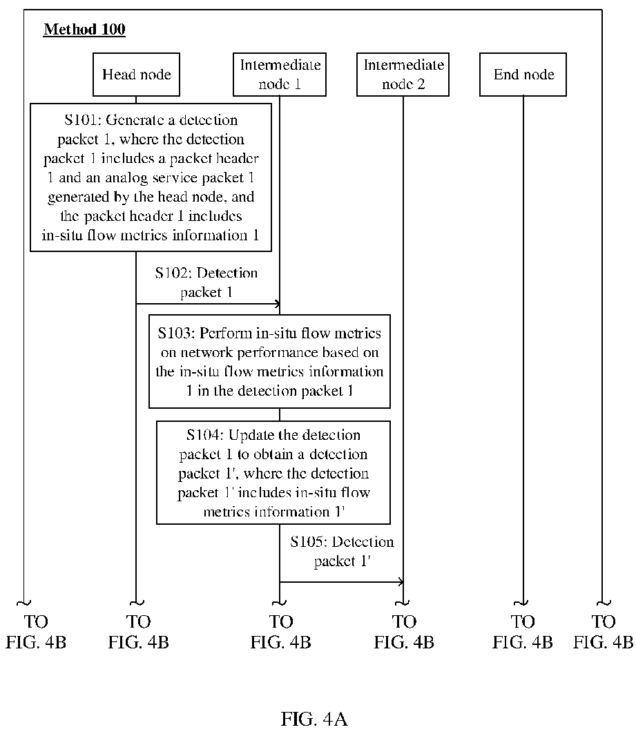
Description
- This application claims priority to
Chinese Patent Application No. 202010112503.3, filed with the China National Intellectual Property Administration on February 24, 2020 Chinese Patent Application No. 202010006017.3, filed with the China National Intellectual Property Administration on January 3, 2020 - This application relates to the field of communications technologies, and in particular, to an active in-situ flow metrics method, a network device, and a communications system.
- Network performance detection technologies are a research hotspot in the telecommunications field. The network performance detection technologies analyze, control, and adjust a network running status by monitoring, measuring, and collecting network performance data, to provide stable network services. This is the basis of network running. The network performance detection technologies may include active metrics (English: Active Metrics) and passive metrics (English: Passive Metrics) based on measurement methods.
- Active metrics are to actively send a detection flow to a network and analyze a network behavior based on a characteristic change that occurs when the detection flow is affected by the network. A measured network performance indicator usually includes one or more of a packet loss rate, a delay, jitter, and bandwidth. Common active measurement protocols include PING, Traceroute, an Internet protocol measurement protocol (English: Internet Protocol Measurement Protocol, IPMP for short), a two-way active measurement protocol (English: Two-Way Active Measurement Protocol, OWAMP for short), and the like. Active metrics are flexible. However, conventional active metrics indirectly simulate a real service by sending an analog detection packet out of band. However, in this detection manner, real service traffic is not measured, consistency of the analog packet and a real service path cannot be ensured, network service quality cannot be completely and truly reflected, and accuracy of the active metrics is deviated from a real network.
- Passive metrics are detection technologies that use an in-situ flow metrics technology to directly measure a real service flow sent by user equipment. The in-situ flow metrics technology may be, for example, a detection technology such as in-situ operations administration and maintenance (English: in-situ Operations Administration and Maintenance, IOAM for short), in-situ flow information telemetry (English: In-situ Flow Information Telemetry, IFIT for short), or in-band network telemetry (In-band Network Telemetry, INT for short). In passive metrics, measurement is performed based on a real service flow, and therefore detection accuracy is relatively high. However, passive metrics need be performed based on real service traffic sent by the user equipment. In some network scenarios lacking real service traffic, a current passive metrics technology cannot detect network performance. Therefore, how to provide a new detection mechanism that can cover various scenarios of network performance detection becomes a technical problem that currently needs to be resolved.
- On this basis, embodiments of this application provide an active in-situ flow metrics method, a network device, and a communications system, and provide a new detection mechanism, in other words, configure an extended in-situ flow metrics protocol, so that in a network scenario in which there is no real service traffic, effective in-situ flow measurement can also be performed on network performance based on an in-situ flow metrics technology, thereby implementing network performance detection in various scenarios.
- According to a first aspect, an active in-situ flow metrics method is provided. When a head node (namely, a first network node) in a detection domain to which in-situ flow metrics are applied does not receive a real service packet, the method may include: The first network node generates a first analog service packet. The first analog service packet is not a real service packet sent by user equipment. The first network node generates a first detection packet. The first detection packet includes a first packet header and the first analog service packet, a first forwarding path that is of the first detection packet in the detection domain and that is determined based on the first analog service packet is used to simulate a forwarding path, in the detection domain, of a first real service packet sent by the user equipment, the first packet header includes first in-situ flow metrics information, the first in-situ flow metrics information is used by a node in the first forwarding path to perform in-situ flow metrics on network performance, the first in-situ flow metrics information includes first indication information, and the first indication information is used to instruct an end node in the detection domain not to forward the first detection packet to another node. The first network node sends the first detection packet to the end node in the detection domain along the first forwarding path.
- It can be learned that in this embodiment of this application, a current in-situ flow metrics protocol is extended, so that even in a network scenario in which there is no real service traffic, the head node in the detection domain can autonomously generate a detection packet used for in-situ flow metrics, making it possible to perform in-situ flow measurement on network performance based on an in-situ flow metrics technology. Therefore, the method provided in this embodiment of this application is equivalent to providing a new in-situ flow metrics mechanism, and only one extended in-situ flow metrics protocol needs to be configured to complete both active in-situ flow metrics and passive in-situ flow metrics, so that various scenarios of network performance detection can be covered, thereby facilitating network performance detection. In addition, in this embodiment, when an active in-situ flow metrics technology is used, a detection packet generated by the head node further needs to carry indication information to notify the end node that the end node receives a detection packet exclusively used for network performance measurement and indicate the end node not to forward the detection packet to another node. In this way, the detection packet that is not a real service packet and that is exclusively used for measurement is terminated by the end node, and is not forwarded by the end node to a node outside the detection domain, so that a real service provided for a user is prevented from being affected, thereby making the network performance detection mechanism more intelligent.
- For example, the first packet header may include a first in-situ flow metrics header, and the first in-situ flow metrics header includes the first indication information. The first indication information is information indicated by at least one bit included in the first in-situ flow metrics header. For example, for IFIT in-situ flow metrics, the first in-situ flow metrics header may be a flow instruction header FIH field, and the first indication information may be a value of a flag bit R in the FIH. For example, when the value of the flag bit R is 0, it may indicate that the first detection packet is passive in-situ flow metrics. On the contrary, when the value of the flag bit R is 1, it may indicate that the first detection packet is active in-situ flow metrics.
- For another example, the first packet header may include a first extended in-situ flow metrics header, the first extended in-situ flow metrics header is used to carry the first indication information, and a type field of the first extended in-situ flow metrics header indicates that the in-situ flow metrics are active in-situ flow metrics. IFIT in-situ flow metrics are still used as an example. The first extended in-situ flow metrics header may be specifically an FIEH. In this case, the first indication information may be, for example, a value of a type field of the FIEH, and the value of the type field of the FIEH is used to indicate that the in-situ flow metrics are active in-situ flow metrics or passive in-situ flow metrics. Alternatively, the first indication information may be a value of any preset field or flag bit that may be used as an indication in the FIEH.
- For still another example, the first packet header may include an option OPTION field, and the OPTION field includes the first indication information. For example, the first indication information is information indicated by at least one bit included in the OPTION field. For another example, the first indication information is information indicated by a type field of the OPTION field, and the type field indicates that the in-situ flow metrics are active in-situ flow metrics. IFIT in-situ flow metrics are still used as an example. The first indication information may be specifically information indicated by a type Type field of an extended OPTION field, or the
first indication information 1 may be values of one or more bits of a reserved Reserved field or another field of an extended OPTION field. IOAM in-situ flow metrics are used as an example. The first indication information may be specifically information indicated by an IOAM Type field of the extended OPTION field, or the first indication information may be values of one or more bits of IOAM data Data. The first packet header may be encapsulated in an IPv6 packet header, a VXLAN packet header, an IPv4 packet header, or an SRH. - The three examples are merely example descriptions of adding the first indication information to the first detection packet in this embodiment of this application. The foregoing three possible implementations are included but do not constitute a limitation. Any other information that can be used to indicate that the in-situ flow metrics are active in-situ flow metrics may be used as the first indication information in this embodiment of this application, and any packet header that can carry the first indication information may be used as the first packet header in this embodiment of this application.
- It should be noted that the in-situ flow metrics may be IFIT in-situ flow metrics, IOAM in-situ flow metrics, or INT in-situ flow metrics. Any in-situ flow metrics protocol may be extended by using the method provided in this embodiment of this application to support the active in-situ flow metrics method provided in this embodiment of this application.
- The in-situ flow metrics provided in this embodiment of this application may be edge-to-edge E2E active in-situ flow metrics, or may be hop-by-hop active in-situ flow metrics. Details may be flexibly set based on an in-situ flow metrics requirement. In E2E active in-situ flow metrics, each node in the first forwarding path in the detection domain sends a measurement result of the node to a control management device after performing network performance detection. In hop-by-hop in-situ flow metrics, after performing network performance detection, a node other than the end node in the first forwarding path in the detection domain adds a measurement result of the node to a detection packet and sends the measurement result to a next-hop node, until the end node obtains a measurement result of the end node and sends the measurement result of the end node and a measurement result of each node in the first forwarding path in the detection domain to the control management device after performing network performance detection. The control management device performs analysis and manages traffic of the detection domain.
- In a possible implementation, a specific process in which the first network node generates the first detection packet may include: The first network node generates the first analog service packet. The first network node encapsulates the first in-situ flow metrics information in the first analog service packet.
- For example, the first analog service packet may be a layer-2 packet, the layer-2 packet includes a virtual local area network VLAN identifier, and the VLAN identifier is used to identify a VLAN to which the user equipment belongs. This embodiment of this application may further include: The first network node receives the first real service packet. The first real service packet carries a same VLAN identifier as the first analog service packet. The first network node forwards the first real service packet to the end node along the first forwarding path. For a private-line service, considering that a layer-2 packet is forwarded under guidance of a VLAN to which the layer-2 packet belongs, the layer-2 analog service packet generated by the head node carries a VLAN identifier carried in the real service packet, and simulates the layer-2 real service packet to enter an ingress port on the head node, so that the analog service packet is transmitted in the detection domain along a same forwarding path as the real service packet, and therefore a measurement result of network performance measurement is of real reference significance to forwarding of the real service packet in the detection domain. For a dedicated-network service, considering that a layer-2 packet is forwarded under guidance of a VLAN to which the layer-2 packet belongs and a destination MAC address of the layer-2 packet, the layer-2 analog service packet generated by the head node carries a VLAN identifier and a destination MAC address that are carried in the real service packet, and simulates the layer-2 real service packet to enter an ingress port on the head node, so that the analog service packet is transmitted in the detection domain along a same forwarding path as the real service packet, and therefore a measurement result of network performance measurement is of real reference significance to forwarding of the real service packet in the detection domain.
- For another example, the first analog service packet may be a layer-3 packet, the layer-3 packet includes a source Internet protocol IP address and a destination IP address, the source IP address is an IP address that belongs to a same network segment as an IP address of an ingress interface used by the first network node to receive the first real service packet, and the destination IP address is an IP address that belongs to a same network segment as an IP address of an egress interface used by the end node to forward the first real service packet to a user side. This embodiment of this application may further include: The first network node receives the first real service packet by using the ingress interface. The first network node forwards the first real service packet to the end node along the first forwarding path. Considering that a layer-3 packet is forwarded under guidance of a source IP address and a destination IP address, and forwarding paths of packets with source IP addresses in a same network segment and destination IP addresses in a same network segment are consistent, because network segments to which the source IP address and the destination IP address that are carried in the layer-3 analog service packet generated by the head node belong are correspondingly the same as network segments to which a source IP address and a destination IP address that are carried in the real service packet belong, the analog service packet is transmitted in the detection domain along a same forwarding path as the real service packet, so that a measurement result of network performance measurement is of real reference significance to forwarding of the real service packet in the detection domain.
- In other specific implementations, this embodiment of this application further includes: The first network node generates a second detection packet. The first detection packet and the second detection packet are different in at least one of a protocol number, a transmission control protocol TCP port number, and a user datagram protocol UDP port number. The second detection packet includes a second packet header and a second analog service packet generated by the first network node, a second forwarding path that is of the second detection packet in the detection domain and that is determined based on the second analog service packet is used to simulate a forwarding path, in the detection domain, of a second real service packet sent by the user equipment, the second packet header includes second in-situ flow metrics information, the second in-situ flow metrics information is used by a node in the second forwarding path to perform in-situ flow metrics on network performance, the second in-situ flow metrics information includes second indication information, and the second indication information is used to indicate the end node not to forward the second detection packet to another node. The first network node forwards the second detection packet to the end node along the second forwarding path.
- In this implementation, this embodiment of this application may further include: The first network node receives the second real service packet sent by the user equipment. The second real service packet and the second detection packet carry a same protocol number and a same TCP port number or UDP port number. The first network node forwards the second real service packet to the end node along the second forwarding path.
- In this way, in this implementation, a plurality of forwarding paths with a same head node and a same end node in the detection domain can be detected to provide data support for normal transmission, in a network, of different real service packets that need to be transmitted along different forwarding paths, so that the network performance detection mechanism can adapt to more network scenarios, thereby implementing more complete network performance measurement in the detection domain.
- According to a second aspect, an embodiment of this application further provides a method for actively detecting network performance based on in-situ flow metrics. The method is applied to a detection domain of in-situ flow metrics, and is performed by any node, namely, a second network node, after a head node in the detection domain. For example, the method may include: The second network node in the detection domain receives, by using a first forwarding path in the detection domain, a first detection packet sent by a first network node in the detection domain. The first detection packet includes a first packet header and a first analog service packet, the first packet header includes first in-situ flow metrics information, the first in-situ flow metrics information includes indication information, the indication information is used to instruct an end node in the detection domain not to forward the first detection packet to another node, the first analog service packet is not a real service packet sent by user equipment, and the first forwarding path is used to simulate a forwarding path, in the detection domain, of a first real service packet sent by the user equipment. The second network node performs in-situ flow metrics on network performance based on the first in-situ flow metrics information.
- For example, the second network node may be the end node in the detection domain, and after the second network node detects the network performance, the method may further include: The second network node does not forward the first detection packet to another node according to the indication information.
- For another example, the second network node may be an intermediate node in the detection domain, and the method may further include: The second network node updates the first detection packet to obtain a second detection packet. The second detection packet includes second in-situ flow metrics information, and the second in-situ flow metrics information includes indication information. The second network node forwards the second detection packet to the end node along the first forwarding path.
- In a possible implementation, the first analog service packet may be a layer-2 packet, the layer-2 packet includes a virtual local area network VLAN identifier, and the VLAN identifier is used to identify a VLAN to which the user equipment belongs. In this case, the first network node receives the first real service packet sent by the user equipment. The first real service packet carries a VLAN identifier. The first network node may forward the first real service packet to the end node along the first forwarding path.
- In another possible implementation, the first analog service packet is a layer-3 packet, the layer-3 packet includes a source Internet protocol IP address and a destination IP address, the source IP address is an IP address that belongs to a same network segment as an IP address of an ingress interface used by the head node in the detection domain to receive the first real service packet sent by the user equipment, and the destination IP address is an IP address that belongs to a same network segment as an IP address of an egress interface used by the end node to forward the first real service packet to a user side.
- It can be learned that in scenarios of both the layer-2 packet and the layer-3 packet, in this embodiment of this application, the analog service packet can be transmitted in the detection domain along a same forwarding path as the real service packet, so that a measurement result of network performance measurement is of real reference significance to forwarding of the real service packet in the detection domain.
- The in-situ flow metrics are IFIT in-situ flow metrics, IOAM in-situ flow metrics, or INT in-situ flow metrics.
- The in-situ flow metrics are edge-to-edge active in-situ flow metrics or hop-by-hop active in-situ flow metrics.
- It should be noted that for a specific implementation and an achieved effect of the method provided in the second aspect of embodiments of this application, refer to related descriptions in the embodiment described in the first aspect, and details are not described herein again.
- According to a third aspect, this application further provides a first network device, including a transceiver unit and a processing unit. The transceiver unit is configured to perform a receiving/sending operation in the method provided in the first aspect, and the processing unit is configured to perform an operation other than the receiving/sending operation in the first aspect. For example, when the first network device performs the method according to the first aspect, the transceiver unit is configured to send a first detection packet to an end node in a detection domain along a first forwarding path, and the processing unit is configured to generate the first detection packet.
- According to a fourth aspect, an embodiment of this application further provides a second network device. The second network device includes a transceiver unit and a processing unit. The transceiver unit is configured to perform a receiving/sending operation in the method provided in the second aspect, and the processing unit is configured to perform an operation other than the receiving/sending operation in the second aspect. For example, when the second network device performs the method according to the second aspect, the transceiver unit is configured to receive, by using a first forwarding path in a detection domain, a first detection packet sent by a first network node in the detection domain, and the processing unit is configured to perform in-situ flow metrics on network performance based on first in-situ flow metrics information.
- According to a fifth aspect, an embodiment of this application further provides a first network device, including a first communications interface, a second communications interface, and a processor. The first communications interface is configured to perform a receiving operation in the method provided in the first aspect, the second communications interface is configured to perform a sending operation in the method provided in the first aspect, and the processor is configured to perform an operation other than the receiving and sending operations in the method provided in the first aspect.
- According to a sixth aspect, an embodiment of this application further provides a second network device, including a first communications interface, a second communications interface, and a processor. The first communications interface is configured to perform a receiving operation in the method provided in the second aspect, the second communications interface is configured to perform a sending operation in the method provided in the second aspect, and the processor is configured to perform an operation other than the receiving and sending operations in the method provided in the second aspect.
- According to a seventh aspect, an embodiment of this application further provides a first network device. The first network device includes a memory and a processor. The memory includes computer-readable instructions, and the processor communicating with the memory is configured to execute the computer-readable instructions, so that the first network device is configured to perform the method provided in the first aspect.
- According to an eighth aspect, an embodiment of this application further provides a second network device. The second network device includes a memory and a processor. The memory includes computer-readable instructions, and the processor communicating with the memory is configured to execute the computer-readable instructions, so that the second network device is configured to perform the method provided in the second aspect.
- According to a ninth aspect, an embodiment of this application further provides a computer-readable storage medium. The computer-readable storage medium stores instructions, and when the instructions run on a computer, the computer performs the active in-situ flow metrics method provided in the first aspect or the second aspect.
- According to a tenth aspect, an embodiment of this application further provides a computer program product, including a computer program or computer-readable instructions. When the computer program or the computer-readable instructions run on a computer, the computer performs the active in-situ flow metrics method provided in the first aspect or the second aspect.
- According to an eleventh aspect, an embodiment of this application further provides a communications system. The communications system includes the first network device provided in the third aspect, the fifth aspect, or the seventh aspect and the second network device provided in the fourth aspect, the sixth aspect, or the eighth aspect.
-
-
FIG. 1 is a schematic diagram of a header structure of IFIT information according to an embodiment of this application; -
FIG. 2 is a schematic diagram of a network system framework in an application scenario according to an embodiment of this application; -
FIG. 3 is a schematic diagram of a network system framework in another application scenario according to an embodiment of this application; -
FIG. 4A andFIG. 4B are a schematic flowchart of an active in-situflow metrics method 100 according to an embodiment of this application; -
FIG. 5a is a schematic diagram of a format of an extended OPTION field in adetection packet 1 in a case of IFIT according to an embodiment of this application; -
FIG. 5b is a schematic diagram of a format of an extended OPTION field in adetection packet 1 in a case of IOAM according to an embodiment of this application; -
FIG. 6A andFIG. 6B are a schematic flowchart of an active in-situflow metrics method 200 according to an embodiment of this application; -
FIG. 7A ,FIG. 7B , andFIG. 7C are a schematic diagram of an active in-situ flow metrics method in a scenario according to an embodiment of this application; -
FIG. 8 is a schematic flowchart of an active in-situflow metrics method 400 according to an embodiment of this application; -
FIG. 9 is a schematic flowchart of an active in-situflow metrics method 500 according to an embodiment of this application; -
FIG. 10 is a schematic diagram of a structure of afirst network device 1000 according to an embodiment of this application; -
FIG. 11 is a schematic diagram of a structure of asecond network device 1100 according to an embodiment of this application; -
FIG. 12 is a schematic diagram of a structure of afirst network device 1200 according to an embodiment of this application; -
FIG. 13 is a schematic diagram of a structure of asecond network device 1300 according to an embodiment of this application; -
FIG. 14 is a schematic diagram of a structure of afirst network device 1400 according to an embodiment of this application; -
FIG. 15 is a schematic diagram of a structure of asecond network device 1500 according to an embodiment of this application; and -
FIG. 16 is a schematic diagram of a structure of acommunications system 1600 according to an embodiment of this application. - The following describes technical solutions of embodiments of this application with reference to the accompanying drawings. A network architecture and a service scenario described in embodiments of this application are intended to describe the technical solutions in embodiments of this application more clearly, and do not constitute any limitation on the technical solutions provided in embodiments of this application. A person of ordinary skill in the art may know that, with evolution of the network architecture and emergence of a new service scenario, the technical solutions provided in embodiments of this application are also applicable to a similar technical problem.
- Ordinal numbers such as "1", "2", "3", "first", "second", and "third" in this application are used to distinguish between a plurality of objects, but are not used to limit a sequence of the plurality of objects.
- "A and/or B" mentioned in this application should be understood as including the following cases: Only A is included, only B is included, or both A and B are included.
- An IOAM-based in-situ flow metrics technology in this application means that when a data packet is transmitted in a detection domain, OAM information is carried in the data packet. "In-situ" (English: in-situ) means that the OAM information is added to the data packet instead of being carried in a dedicated OAM packet.
- For an IFIT-based in-situ flow metrics technology, refer to related descriptions in an Internet engineering task force (English: Internet Engineering Task Force, IETF for short) draft "In-situ Flow Information Telemetry draft-song-opsawg-ifit-framework-10". The draft is incorporated herein by reference in its entirety.
- For an INT-based in-situ flow metrics technology in this application, refer to related descriptions in an IETF draft "Data-plane for in-band telemetry collection draft-lapukhov-dataplane-prove-01". The draft is incorporated herein by reference in its entirety.
- It should be noted that with development of various in-situ flow metrics technologies, in-situ flow metrics technologies mentioned in this application include various developed in-situ flow metrics technologies.
- The following briefly describes some technical terms in this application.
- Customer: A customer refers to user equipment in this application. "User equipment" and "customer" may often be used interchangeably. It should be understood that the two have a same meaning.
- In-situ flow metrics: In-situ flow metrics, which may also be referred to as in-situ flow measurement, means detecting network performance with a service flow. Network performance detection may include, for example, detecting a service channel carrying a service and network performance of a corresponding network element. The service channel may be a forwarding path of a service flow, and the network performance may include, for example, a transmission delay, a packet loss rate, jitter, and a bit error rate.
- Analog service packet: In this application, an analog service packet is generated by a detection node in an in-situ flow metrics domain when there is no real service traffic in a network to simulate a real service packet sent by user equipment. A forwarding path of the analog service packet in the detection domain is consistent with a forwarding path of the real service packet sent by the user equipment. After receiving the analog service packet, an end node in the detection domain does not forward the analog service packet like another node in the network.
- Real service packet: A real service packet is real service traffic that is transmitted in a network and that is sent by user equipment. When receiving the real service packet, an end node in a detection domain needs to forward the packet to a destination address of the real service packet.
- The following uses an IFIT technology as an example to describe the in-situ flow metrics technology.
- In the IFIT technology, feature marking may be performed, by using IFIT information carried in a packet, on a node through which a service flow in a network passes. The feature marking may also be referred to as coloring. The IFIT information may constitute an IFIT header as a whole, for example, may be used as an extension header of a multi-protocol label switching (English: Multi-Protocol Label Switching, MPLS for short) protocol. Alternatively, the IFIT information may be scattered and included in, for example, an Internet protocol (English: Internet Protocol, IP) header based on field information or the like. Each hop of node through which the service flow passes reports collected data such as a timestamp and a packet count to a network management device, so that the network management device further calculates a network delay, a packet loss status, a restoration path, and the like based on the reported data. In a point-to-point flow transmission service scenario, a possible header structure that is of the IFIT information and that is used in an MPLS protocol network is shown in
FIG. 1 , and key fields in the IFIT header structure are described herein. - 1. Flow instruction indicator (English: Flow Instruction Indicator, FII for short) field: The field is mainly used to indicate that subsequent data information is IFIT information. For example, the following field information may be included:
- a flow instruction indicator label (English: FII Label), where a default value may be configured to identify an IFIT detection flow; and
- a flag bit S, used to indicate whether the flow instruction indicator label is at the bottom of a stack, where for example, a
value 1 indicates that the flow instruction indicator label is at the bottom of the stack, and avalue 0 indicates that the flow instruction indicator label is not at the bottom of the stack, where - some related information such as a priority EXP and time to live (English: Time To Live, TTL for short) in an outer MPLS label header may be inherited.
- 2. Flow instruction header (English: Flow Instruction Header, FIH for short) field, which may also be referred to as an in-situ flow metrics header or a flow detection header. The field is mainly used to carry information related to IFIT detection. For example, the following field information may be included:
- a flow identifier (English: Flow ID), which is a globally unique identifier allocated to each piece of IFIT detection traffic;
- a flag bit L, used for packet loss (English: packet loss) detection coloring marking, where for example, a value "1" of the flag bit L indicates that a packet loss is collected, and "0" indicates that no packet loss is collected;
- a flag bit D, used for delay (English: delay) measurement coloring marking, where for example, a value "1" of the flag bit D indicates that a timestamp is collected, and "0" indicates that no timestamp is collected;
- a header type indicator (English: Header Type Indicator, HTI for short), marking a range of nodes that need to send IFIT detection results and a range of detection content, where for example, different mark values may be used to distinguish whether to detect a path node with an IFIT capability in addition to nodes at two ends and whether a flow instruction extension header (English: Flow Instruction Extension Header, FIEH for short) field is included; and
- a flag bit R, which may be used as a reserved flag bit.
- 3. Flow instruction extension header FIEH field, which may also be referred to as a flow extension detection header or an extension in-situ flow metrics header: The field serves as an extension field, and is mainly used to carry other information related to IFIT detection. For example, the following field information may be included:
- a flow identifier extension Flow ID Ext, used to extend a flow identifier bit width;
- a flag bit V, used to mark a reverse flow (English: reverse flow), where for example, a value "0" of the flag bit V indicates that a current flow is a forward flow and a receive end may automatically create a reverse flow, and "1" indicates that a current flow is a reverse flow and the receive end does not automatically create a reverse flow; and
- a period (English: Period), where different values indicate different detection periods, and the detection period may be, for example, 1s, 10s, 30s, 1 min, or 10 min.
- Generally, after receiving a packet sent by user equipment, a head node in a detection domain encapsulates IFIT information (namely, in-situ flow metrics information) in the packet to indicate a network node in the detection domain to perform IFIT detection. A type of the packet may be, for example, a data packet or a control packet. In an actual application scenario, a plurality of data packets or control packets may be continuously sent, for example, a plurality of data packets may constitute one data stream; or a plurality of data packets or control packets such as operations administration and maintenance (English: Operation, Administration and Maintenance, OAM for short) control packets are sent at intervals in a specific period.
- In a network, a network range in which IFIT detection needs to be performed may be determined by specifying a detection domain. Generally, a network node in the detection domain needs to transmit IFIT information to implement IFIT detection, and sends corresponding information obtained after the IFIT detection to a network management device. A detection range of the detection domain may be determined based on a plurality of manners, for example, may be determined based on a network scenario, where for example, a core network part in the network is specified as the detection domain; or may be determined based on a service type, where for example, detection domains of different ranges are specified for a video service and a voice service. An IFIT network includes three types of nodes, which are specifically a head node (English: head node), an end node (English: end node), and hops of path nodes (English: path node). The hops of path nodes may also be referred to as intermediate nodes. The head node, the end node, and the path node may be, for example, corresponding network nodes in the network. For a data stream, the first network node transmitting the data stream within a specified detection range of the detection domain may be used as a head node for transmitting the data stream. The last network node transmitting the data stream within the specified detection range of the detection domain may be used as an end node for transmitting the data stream. Nodes transmitting the data stream between the head node and the end node are hops of path nodes. The IFIT information may be added by the head node and peeled off by the end node.
- The detection domain in this application is a network domain to which in-situ flow metrics are applied. Specifically, the detection domain includes a plurality of forwarding devices, for example, a router or a switch, for which an in-situ flow metrics function is enabled. The detection domain may further include a control management device such as a logical centralized controller, configured to: perform in-situ flow metrics configuration on the plurality of forwarding devices in the detection domain, and collect and analyze in-situ flow metrics data reported by the plurality of forwarding devices.
- An active in-situ flow metrics technology in this application is described with reference to the in-situ flow metrics technology described above.
- Active in-situ flow metrics mean that based on the in-situ flow metrics technology described above, when a head node in a detection domain does not receive real service traffic sent by user equipment, the head node actively generates detection traffic, and encapsulates in-situ flow metrics information in the detection traffic. For example, if IFIT in-situ flow metrics are used as a basis, a detection packet carries IFIT in-situ flow metrics information. The head node sends the detection packet to an end node along a forwarding path of the detection packet, and a node in the forwarding path in the detection domain may measure network performance based on the received detection packet. In this application, active in-situ flow metrics are an extension of conventional passive in-situ flow metrics, so that an in-situ flow metrics protocol supports an active metrics capability, thereby implementing high-precision detection of network performance when there is no real service traffic. In this application, whether the forwarding path meets a service bearer requirement may be determined based on a measurement result of the active in-situ flow metrics. Therefore, a scenario in which there is real service traffic and a scenario lacking real service traffic can be covered based on a same in-situ flow metrics protocol. Equivalent to a technical solution in which an out-of-band measurement protocol is used to measure network performance in a case of no real service traffic and network performance in a case of real traffic is tested based on in-situ flow metrics, the solution provided in this application only requires one measurement protocol, configuration is simple, and the solution is compatible with a plurality of network scenarios.
-
FIG. 2 is a schematic diagram of a network architecture according to an embodiment of this application. Anetwork 100 includes a control management device and a plurality of network nodes. The plurality of network nodes are connected by using a communications link and are configured to transmit a data stream. As shown inFIG. 2 , a head node, anintermediate node 1, anintermediate node 2, and an end node in a detection domain are connected by using a communications link. In addition to the nodes shown in the figure, the detection domain may include other nodes not shown. The end node may also be connected to an external node by using a communications link. A data stream sent by user equipment may pass through the head node, theintermediate node 1, theintermediate node 2, and the end node along aforwarding path 1, to reach the external node. The control management device may be, for example, a centralized controller, a network management center, or a traffic analysis device that performs a traffic analysis function. The control management device may be one device, or may be a set of a plurality of devices. - The control management device may be configured to perform information collection and transmission path performance detection on a data packet in a transmission path between the plurality of network nodes. The transmission path performance detection includes but is not limited to detection of a transmission delay, a packet loss rate, and a packet loss location. In this embodiment of this application, the transmission path may include a path through which a data stream passes. In this application, the control management device may determine a detection domain. The detection domain is a detection range determined by the control management device. Alternatively, each forwarding device in a detection domain may perform configuration to obtain the detection domain. In a transmission path in the detection domain, network nodes located between a head node and an end node in the detection domain are intermediate nodes, for example, the
intermediate node 1 and theintermediate node 2 inFIG. 2 . -
FIG. 3 is a schematic diagram of another network architecture according to this application. Anetwork 200 shown inFIG. 3 mainly differs from thenetwork 100 shown inFIG. 2 in that a plurality of transmission paths exist between a head node and an end node. In a specific implementation, the plurality of transmission paths include at least aforwarding path 1 and aforwarding path 2 shown inFIG. 3 . A data stream sent by user equipment may pass through the head node, anintermediate node 1, anintermediate node 2, and the end node along the forwardingpath 1, to reach an external node; or may pass through the head node, anintermediate node 3, anintermediate node 4, and the end node in a detection domain along the forwardingpath 2, to reach an external node. In a possible implementation, the forwardingpath 1 may be a working path, and theforwarding path 2 may be a protection path. When the forwardingpath 1 is faulty, the forwardingpath 2 carries service traffic. In another possible implementation, the forwardingpath 1 and theforwarding path 2 may be equivalent paths. When receiving a service flow sent by the user equipment, the head node selects, through hash calculation, the forwardingpath 1 to carry service traffic. - It should be understood that
FIG. 2 orFIG. 3 only shows, as examples, four nodes included in the detection domain, and the detection domain may include any other quantity of nodes. This is not limited in embodiments of this application. The network architecture shown inFIG. 2 orFIG. 3 is merely an example for description. An application scenario of in-situ flow metrics provided in this application is not limited to the scenario shown inFIG. 2 orFIG. 3 . The technical solution provided in this application is applicable to all network scenarios in which the in-situ flow metrics technology is used to perform data transmission. - In the scenario shown in
FIG. 2 orFIG. 3 , when the shown node devices in the detection domain are enabled, and configuration of a service channel between the head node and the end node is completed, it is expected to perform performance detection on the service channel to determine whether the service channel meets a service bearer requirement, for example, a requirement on an indicator such as a delay, bandwidth, or a packet loss rate. For another example, in the scenario shown inFIG. 3 , when being used as a protection path, the forwardingpath 2 usually does not carry real service traffic, and it is expected to measure a performance indicator of theforwarding path 2 to determine whether the protection path meets a service bearer requirement, so that when a working path is faulty, traffic can be switched to a protection path that meets the service bearer requirement. In the foregoing two possible specific network application scenarios, performance detection cannot be completed based on a current in-situ flow metrics technology. However, if an out-of-band traffic measurement method is used together for measurement, protocol configuration is quite complicated. - In view of this, to resolve the foregoing problem, this application provides an active in-situ
flow metrics method 100. An in-situ flow metrics protocol is extended to support an active metrics capability, so that in a network scenario in which there is no real service traffic, in-situ flow measurement can also be performed on network performance based on an in-situ flow metrics technology. With reference toFIG. 4A andFIG. 4B , the following uses the scenario shown inFIG. 3 as an example to briefly describe the active in-situflow metrics method 100 in this application. -
FIG. 4A andFIG. 4B show an active in-situflow metrics method 100 according to an embodiment of this application. Themethod 100 may include, for example, the following S101 to S110. - S101: A head node in a detection domain generates a
detection packet 1, where thedetection packet 1 includes apacket header 1 and ananalog service packet 1 generated by the head node, and thepacket header 1 includes in-situflow metrics information 1. - It should be noted that in a network to which the
method 100 in this embodiment of this application is applied, any extended in-situ flow metrics protocol may be configured to support execution of S101 to S110 in themethod 100. The in-situ flow metrics protocol may be, for example, any one of an IFIT protocol, an IOAM protocol, and an INT protocol. In this embodiment of this application, in-situ flow metrics performed by the head node, anintermediate node 1, anintermediate node 2, and an end node are consistent with the configured protocol. In other words, the in-situ flow metrics performed are any one of IFIT in-situ flow metrics, IOAM in-situ flow metrics, and INT in-situ flow metrics. - In this embodiment of this application, a function module that can generate a detection packet is provided on the head node in the detection domain, and the function module may be referred to as a packet transmitter. When network performance detection needs to be performed on a
forwarding path 1 in the detection domain, but no real packet is currently transmitted in theforwarding path 1 of the network, the head node in theforwarding path 1 in the detection domain may generate thedetection packet 1 to implement the active in-situflow metrics method 100 to perform network performance measurement on nodes and links included in theforwarding path 1. - In a specific implementation, a process in which the head node generates the
detection packet 1 may specifically include: S11: The head node generates theanalog service packet 1. S12: The head node encapsulates, in theanalog service packet 1, thepacket header 1 including the in-situflow metrics information 1, to obtain thedetection packet 1. - The generated
detection packet 1 varies with a network environment. Thepacket header 1 is adaptably encapsulated based on a packet type of thedetection packet 1. For example, for an Internet protocol version 4 (English:Internet Protocol version 4, IPv4 for short) network environment, thedetection packet 1 is an IPv4 packet, and thepacket header 1 may be encapsulated in an option OPTION field of the IPv4 packet. For another example, for an Internet protocol version 6 (English: Internet Protocol version 6, IPv6 for short) network environment, thedetection packet 1 is an IPv6 packet, and thepacket header 1 may be encapsulated in an IPv6 packet header (for example, a hop-by-hop (English: Hop By Hop) header). For still another example, for a segment routing IPv6 (English: Segment Routing IPv6, SRv6 for short) network environment, thedetection packet 1 is an SRv6 packet, and thepacket header 1 may be encapsulated in an SRv6 extension header (English: Segment Routing Header, SRH for short) of the SRv6 packet. For yet another example, for an MPLS network environment, thepacket header 1 may be encapsulated in an MPLS packet header. It should be noted that a person skilled in the art may specifically encapsulate thepacket header 1 in this embodiment of this application based on existing common knowledge, to generate acorresponding detection packet 1. - The
analog service packet 1 generated in S11 is not a real service packet sent by the user equipment to the head node, but an analog packet that is transmitted in the detection domain along the forwardingpath 1 and that is generated by the head node to simulate areal service packet 1 that may be sent by the user equipment along the forwardingpath 1. Thepacket header 1 in S12 is a packet header encapsulated, after theanalog service packet 1 is generated, in theanalog service packet 1 to generate thedetection packet 1. The in-situflow metrics information 1 in thepacket header 1 is used to indicate each node in theforwarding path 1 to perform in-situ flow metrics on network performance. In addition, the in-situflow metrics information 1 further includesindication information 1, and theindication information 1 is used to indicate the end node in theforwarding path 1 in the detection domain not to forward thedetection packet 1 to another node. In this way, the following case can be effectively avoided: The end node uses the detection packet as a real service packet, and sends the packet to a node outside the detection domain, affecting a service provided for a user. - The
analog service packet 1 may be a layer-2 packet or a layer-3 packet. Whether the head node specifically generates a layer-2analog service packet 1 or a layer-3analog service packet 1 may depend on whether thereal service packet 1 is a layer-2 packet or a layer-3 packet. Specifically, if thereal service packet 1 transmitted by the head node along the forwardingpath 1 is a layer-2 packet, the generatedanalog service packet 1 may be a layer-2 packet. If thereal service packet 1 transmitted by the head node along the forwardingpath 1 is a layer-3 packet, the generatedanalog service packet 1 may be a layer-3 packet. - For example, both the
analog service packet 1 and thereal service packet 1 are layer-2 packets, and thereal service packet 1 carries a virtual local area network (English: Virtual Local Area Network, VLAN for short) identifier. The VLAN identifier is used to identify a VLAN to which the user equipment belongs, and thereal service packet 1 may enter the head node from aport 1, in other words, theport 1 is an ingress port used by the head node to receive thereal service packet 1. In this case, theanalog service packet 1 generated by the head node by simulating thereal service packet 1 may include the VLAN identifier, and may further include a port number corresponding to theport 1. The port number is used to indicate theport 1. In this way, it can be ensured that thedetection packet 1 generated by the head node based on theanalog service packet 1 is also transmitted in the detection domain along the forwardingpath 1. - For example, for a private-line service, a forwarding table included in each node includes a correspondence between an ingress port on the node, a VLAN identifier, and an egress port on the node, and a real service packet is forwarded based on a VLAN to which the real service packet belongs. Therefore, for the
real service packet 1 carrying aVLAN identifier 1, after receiving thereal service packet 1 from theingress port 11, the head node parses out theVLAN identifier 1 carried in thereal service packet 1 to determine anegress port 12 based on theingress port 11 and theVLAN identifier 1, and forwards thereal service packet 1 from theegress port 12 to a next-hop node (namely, the intermediate node 1). Because the forwarding table on each node is unchanged, to simulate theforwarding path 1 of thereal service packet 1 in the detection domain, the generatedanalog service packet 1 needs to carry a same VLAN identifier as thereal service packet 1, in other words, theanalog service packet 1 needs to carry theVLAN identifier 1. In addition, the head node needs to perform, through simulation, configuration that theanalog service packet 1 is received from the ingress port 11 (namely, an ingress port of the real service packet 1). For example, the head node notifies, by using a configuration command, a forwarder responsible for packet forwarding that an ingress port of theanalog service packet 1 is theport 11. Alternatively, for another example, the head node adds, to theanalog service packet 1, a port number used to identify theingress port 11, but needs to delete the port number from theanalog service packet 1 before forwarding theanalog service packet 1 to the next-hop node. In this way, after generating theanalog service packet 1 whose reception from theingress port 11 is simulated, the head node parses out theVLAN identifier 1 carried in theanalog service packet 1 to determine theegress port 12 based on theingress port 11 and theVLAN identifier 1, and forwards theanalog service packet 1 from theegress port 12 to the next-hop node (namely, the intermediate node 1). In addition, because forwarding tables on all subsequent nodes are consistent, it is ensured that theanalog service packet 1 can be forwarded along the forwardingpath 1 of the real service packet in the detection domain. - For another example, for a dedicated-network service, a forwarding table included in each node includes a correspondence between an ingress port on the node, a VLAN identifier, a source media access control (English: Media Access Control Address, MAC for short) address (referred to as a destination MAC address below), and an egress port on the node, and a real service packet is forwarded based on a VLAN to which the real service packet belongs and a destination MAC address of the real service packet. Therefore, for the
real service packet 1 carrying aVLAN identifier 1 and adestination MAC address 1, after receiving thereal service packet 1 from theingress port 11, the head node parses out theVLAN identifier 1 and thedestination MAC address 1 that are carried in thereal service packet 1 to determine anegress port 12 based on theingress port 11, theVLAN identifier 1, and thedestination MAC address 1, and forwards thereal service packet 1 from theegress port 12 to a next-hop node (namely, the intermediate node 1). Because the forwarding table on each node is unchanged, to simulate theforwarding path 1 of thereal service packet 1 in the detection domain, the generatedanalog service packet 1 needs to carry a same VLAN identifier and destination MAC address as thereal service packet 1, in other words, theanalog service packet 1 needs to carry theVLAN identifier 1 and thedestination MAC address 1. In addition, the head node needs to perform, through simulation, configuration that theanalog service packet 1 is received from the ingress port 11 (namely, an ingress port of the real service packet 1). For example, the head node notifies, by using a configuration command, a forwarder responsible for packet forwarding that an ingress port of theanalog service packet 1 is theport 11. Alternatively, for another example, the head node adds, to theanalog service packet 1, a port number used to identify theport 11, but needs to delete the port number from theanalog service packet 1 before forwarding theanalog service packet 1 to the next-hop node. In this way, after generating theanalog service packet 1 whose reception from theingress port 11 is simulated, the head node parses out theVLAN identifier 1 and thedestination MAC address 1 that are carried in theanalog service packet 1 to determine theegress port 12 based on theingress port 11, theVLAN identifier 1, and thedestination MAC address 1, and forwards theanalog service packet 1 from theegress port 12 to the next-hop node (namely, the intermediate node 1). In addition, because forwarding tables on all subsequent nodes are consistent, it is ensured that theanalog service packet 1 can be forwarded along the forwardingpath 1 of the real service packet in the detection domain. - In addition, the
detection packet 1 including theanalog service packet 1 may further carry a source MAC address, a destination MAC address, a source Internet protocol (English: Internet Protocol, IP for short) address, and a destination IP address. The source MAC address may be a MAC address of a node other than nodes in theforwarding path 1 or a MAC address of an interface on a node other than nodes in theforwarding path 1. A destination MAC address of a private-line service may be a MAC address of a node other than the nodes in theforwarding path 1 or a MAC address of an interface on a node other than the nodes in theforwarding path 1. A destination MAC address of a dedicated-network service may be a destination MAC address of thereal service packet 1. The source IP address and the destination IP address each may be any unicast IP address. - Before the
method 100 is performed or after themethod 100 is performed, the head node may further receive thereal service packet 1 from the ingress port (namely, the port 1). Thereal service packet 1 carries the VLAN identifier or thereal service packet 1 carries the VLAN identifier and a destination MAC address. Therefore, the head node may determine an egress port based on a forwarding table stored on the head node, and it is true for each hop of node, so that it is determined that the forwardingpath 1 of thereal service packet 1 in the detection domain sequentially includes the head node, theintermediate node 1, theintermediate node 2, and the end node, in other words, the head node forwards thereal service packet 1 to the end node along the forwardingpath 1. In this way, even if a non-real service packet is used to complete in-situ flow metrics, because a detection packet simulates a forwarding path of a real service packet in the detection domain, the in-situ flow metrics method can completely and truly measure network performance of a forwarding path for transmitting the real service packet in the detection domain. - For another example, both the
analog service packet 1 and thereal service packet 1 are layer-3 packets. Thereal service packet 1 carries a source IP address and a destination IP address. It is known that in the detection domain, an IP address of aningress interface 11 used by the head node to receive thereal service packet 1 is anIP address 11, and an IP address of anegress interface 12 used by the end node to forward thereal service packet 1 to a user side is anIP address 12. It is determined, based on the source IP address and the destination IP address, that a forwarding path of thereal service packet 1 in the network includes the forwardingpath 1 determined based on a network segment to which theIP address 11 belongs and a network segment to which theIP address 12 belongs. If source IP addresses carried in two packets belong to a same network segment and destination IP addresses also belong to a same network segment, forwarding paths that may be determined for the two packets between two nodes are certainly the same. On this basis, to enable theanalog service packet 1 generated by the head node to be transmitted in the detection domain along the forwardingpath 1, the generatedanalog service packet 1 may also include asource IP address 3 and adestination IP address 4. Thesource IP address 3 and theIP address 11 belong to a same network segment, and thedestination IP address 4 and theIP address 12 belong to a same network segment. In this way, it can be ensured that thedetection packet 1 generated by the head node based on theanalog service packet 1 is also transmitted in the detection domain along the forwardingpath 1. - Before the
method 100 is performed or after themethod 100 is performed, the head node may further receive thereal service packet 1 from the ingress interface (namely, the ingress interface 1). In addition, the head node forwards thereal service packet 1 to the end node along the forwardingpath 1. If the end node is not a destination node of thereal service packet 1, the end node forwards thereal service packet 1 to another node from theegress interface 2 on the end node until thereal service packet 1 is forwarded to a user-side device. For example, the user-side device may be a device corresponding to the destination IP address of thereal service packet 1. The device receives thereal service packet 1 to provide a corresponding service for a user. In this way, even if a non-real service packet is used to complete in-situ flow metrics, because a detection packet simulates a forwarding path of a real service packet in the detection domain, the in-situ flow metrics method can completely and truly measure network performance of a forwarding path for transmitting the real service packet in the detection domain. - For example, in the network shown in
FIG. 3 , assuming that the network shown inFIG. 3 is a layer-3 network, when the head node detects network performance of theforwarding path 1, the generatedanalog service packet 1 may carry thesource IP address 3 and thedestination IP address 4. Thesource IP address 3 may be any IP address that belongs to a same network segment as theIP address 11 of theingress interface 11 used by the head node to receive thereal service packet 1, and thedestination IP address 4 may be any IP address that belongs to a same network segment as theIP address 12 of theegress interface 12 used by the end node to send thereal service packet 1. In addition, thedetection packet 1 including theanalog service packet 1 may further carry a source MAC address and a destination MAC address. The source MAC address may be any unicast MAC address other than a MAC address corresponding to theingress interface 1 on the head node, and the destination MAC address may be the MAC address corresponding to theingress interface 1 on the head node. It should be noted that before thedetection packet 1 is forwarded from the head node to theintermediate node 1, the source MAC address needs to be replaced with a MAC address corresponding to an egress interface on the head node, and the destination MAC address needs to be replaced with a MAC address corresponding to an ingress interface on theintermediate node 1, to support normal forwarding of the layer-3 packet. - It should be noted that for the layer-3
analog service packet 1, the generateddetection packet 1 may be specifically an IPv4 or IPv6 packet. - In this embodiment of this application, to provide a high-quality service for the user in the network, the
detection packet 1 needs to be forwarded in the detection domain, and cannot be forwarded from the end node of theforwarding path 1 to another node outside the detection domain. On this basis, in thedetection packet 1 generated by the head node, the in-situflow metrics information 1 not only indicates each node receiving thedetection packet 1 to perform in-situ flow metrics, but also carries theindication information 1 to indicate the end node of theforwarding path 1 in the detection domain not to forward thedetection packet 1 to another node. - The
indication information 1 may specifically correspond to different content based on different network environments. Theindication information 1 may be, for example, obtained by extending a reserved field in an in-situflow metrics header 1 of thepacket header 1, for example, adding at least one bit, where information indicated by the at least one bit is theindication information 1. For another example, an identifier may be added to another field in an in-situflow metrics header 1 of thepacket header 1 to indicate theindication information 1. For still another example, theindication information 1 may be type information obtained after an in-situflow metrics header 1 of thepacket header 1 is extended. Theindication information 1 may be one or more bits. This is not specifically limited in this application. The following describes some specific implementations of theindication information 1 by using examples. - For example, for an MPLS protocol network, the
packet header 1 may be the in-situflow metrics header 1, and theindication information 1 may be a value of a preset field or a flag bit carried in the in-situflow metrics header 1. For example, theindication information 1 may be information indicated by at least one bit included in the in-situflow metrics header 1. IFIT detection is used as an example. Referring toFIG. 1 , the in-situflow metrics header 1 may be a flow instruction header FIH field inFIG. 1 , and theindication information 1 may be, for example, a value of a flag bit R in the FIH. For example, when the value of the flag bit R is 0, it may indicate that thedetection packet 1 is passive in-situ flow metrics. On the contrary, when the value of the flag bit R is 1, it may indicate that thedetection packet 1 is active in-situ flow metrics. For another example, theindication information 1 may be a value of a preset field in the in-situflow metrics header 1. IFIT detection is still used as an example. Referring toFIG. 1 , theindication information 1 may be specifically information indicated by a header type indicator HTI, and a value of the HIT can indicate whether the in-situflow metrics header 1 includes a flow instruction extension header FIEH field or a type of an FIEH. Specifically, when the value of the HIT indicates that the in-situflow metrics header 1 does not include an FIEH or includes an FIEH whose type is passive in-situ flow metrics, it is determined that thedetection packet 1 is passive in-situ flow metrics. On the contrary, when the value of the HIT indicates that the in-situflow metrics header 1 includes an FIEH whose type is active in-situ flow metrics, it is determined that thedetection packet 1 is active in-situ flow metrics. - For another example, still for an MPLS protocol network, the
packet header 1 includes an extended in-situflow metrics header 1, and theindication information 1 may be carried in the extended in-situflow metrics header 1, and may be specifically information indicated by a type field of the extended in-situflow metrics header 1. IFIT detection is used as an example. Referring toFIG. 1 , the extended in-situflow metrics header 1 may be an FIEH shown inFIG. 1 . In this case, theindication information 1 may be, for example, a value of a type field of the FIEH, and the value of the type field of the FIEH is used to indicate that the in-situ flow metrics are active in-situ flow metrics or passive in-situ flow metrics. Alternatively, theindication information 1 may be a value of any preset field or flag bit that may be used as an indication in the FIEH. - For still another example, for an IPv4 or IPv6 protocol network, the
packet header 1 includes an option OPTION field, and the OPTION field may carry theindication information 1. Theindication information 1 may be specifically information indicated by a type field of the OPTION field or information indicated by at least one bit included in the OPTION field. IFIT is used as an example.FIG. 5a shows a format of an extended OPTION field in thedetection packet 1. Theindication information 1 may be specifically information indicated by a type Type field of the extended OPTION field, or theindication information 1 may be values of one or more bits of a reserved Reserved field or another field. IOAM detection is used as an example.FIG. 5b shows a format of an extended OPTION field in thedetection packet 1. Theindication information 1 may be specifically information indicated by an IOAM Type field of the extended OPTION field, or theindication information 1 may be values of one or more bits of IOAM data Data. For IOAM detection, apacket header 1 of IOAM may be specifically encapsulated in an IPv6 packet header, a virtual extensible local area network (English: Virtual Extensible Local Area Network, VXLAN for short) packet header, or an IPv4 packet header. For an SRv6 protocol network, apacket header 1 of IOAM may be alternatively encapsulated in an SRH. - It should be noted that for related descriptions of the in-situ flow metrics technology in this application, refer to related descriptions in the following IETF drafts "IPv6 Application of the Alternate Marking Method draft-fz-6man-ipv6-alt-mark-01", "In-situ OAM IPv6 Options draft-ioametal-ippm-6man-ioam -ipv6-options-02", and "VXLAN-GPE Encapsulation for In-situ OAM Data draft-brockners-ippm-ioam-vxlan-gpe-03". The drafts are incorporated herein by reference in their entireties.
- In some specific implementations, after the head node in the detection domain generates the
detection packet 1, the head node may measure network performance based on the in-situflow metrics information 1 in thedetection packet 1 to obtain ameasurement result 0. - For example, for a specific structure of the head node, refer to a
head node 10 in a network architecture in an embodiment shown inFIG. 7A ,FIG. 7B , andFIG. 7C . In addition to apacket transmitter 101 configured to generate a detection packet, thehead node 10 includes a forwarder 102, and the forwarder 102 includes ameasurement module 1021 configured to implement in-situ flow metrics. In this case, a process in which the head node measures the network performance based on the in-situflow metrics information 1 in thedetection packet 1 may include: S21: Thehead node 10 transmits thedetection packet 1 generated by thepacket transmitter 101 to theforwarder 102. S22: The forwarder 102 identifies that the receiveddetection packet 1 is an active in-situ flow metrics packet, and themeasurement module 1021 measures the network performance based on the in-situflow metrics information 1 in thedetection packet 1 to obtain themeasurement result 0. Themeasurement result 0 may include, for example, a packet count and a timestamp, and is used to reflect network performance of thehead node 10 and a link connected to thehead node 10. - It should be noted that the in-situ
flow metrics information 1 can indicate whether the in-situ flow metrics are active in-situ flow metrics or passive in-situ flow metrics, and further includeidentification information 2 that can indicate whether the in-situ flow metrics are edge-to-edge (English: Edge to Edge, E2E for short) in-situ flow metrics or hop-by-hop in-situ flow metrics. In one case, theidentification information 2 may be theindication information 1, in other words, theindication information 1 can indicate whether thedetection packet 1 is E2E active in-situ flow metrics or hop-by-hop active in-situ flow metrics. In this case, referring to the MPLS network environment shown inFIG. 1 , theindication information 1 may be, for example, information indicated by an HTI field. The following may be defined: HTI=0 indicates "reserved", HTI=1 indicates that thepacket header 1 is a basic E2E FIH (in other words, does not include an FIEH), HTI=2 indicates that thepacket header 1 is a normal hop-by-hop FIH, HTI=3 indicates that thepacket header 1 includes an E2E FIEH (namely, an FIEH whose type is passive in-situ flow metrics), and HTI=4 indicates that thepacket header 1 includes a hop-by-hop FIEH. Based on the foregoing definition, a definition of an extended HTI type may be added. To be specific, the following may be defined: HTI=5 indicates that thepacket header 1 includes an E2E active metrics FIEH, and HTI=6 indicates that thepacket header 1 includes a hop-by-hop active metrics FIEH. In another case, theidentification information 2 may be information other than theindication information 1, and is used to separately identify whether thedetection packet 1 uses an E2E or a hop-by-hop detection mechanism. - It may be understood that in hop-by-hop active in-situ flow metrics, each node in the
forwarding path 1 is required to send an obtained measurement result to a control management device after performing network performance measurement. In E2E active in-situ flow metrics, after performing network performance measurement, each node in theforwarding path 1 is required to add an obtained measurement result to a detection packet and send the measurement result to a next hop, until the end node obtains a corresponding measurement result and then sends, to the control management device, the measurement result of the end node and a measurement result that is carried in the detection packet and that corresponds to each hop of node. For S101, when identifying that the generateddetection packet 1 corresponds to hop-by-hop active in-situ flow metrics, the head node needs to send the obtainedmeasurement result 0 to the control management device and perform S102. When identifying that the generateddetection packet 1 corresponds to E2E active in-situ flow metrics, the head node may add the obtainedmeasurement result 0 to thedetection packet 1 to obtain thedetection packet 1 in S102, to continue to perform themethod 100. - S102: The head node sends the
detection packet 1 to theintermediate node 1 along the forwardingpath 1. - After the head node in the detection domain generates the
detection packet 1, the head node may measure the network performance based on the in-situflow metrics information 1 in thedetection packet 1 to obtain themeasurement result 0. The head node may further send thedetection packet 1 to theintermediate node 1 along the forwardingpath 1, so that theintermediate node 1 measures network performance based on the in-situflow metrics information 1 in thedetection packet 1. - For example, still referring to the network architecture in the embodiment shown in
FIG. 7A ,FIG. 7B , andFIG. 7C , thehead node 10 determines, based on thedetermined forwarding path 1, that a next hop is anintermediate node 11. In this case, theforwarder 102 of the head node may forward thedetection packet 1 to aforwarder 112 of theintermediate node 11. - S103: The
intermediate node 1 performs in-situ flow metrics on the network performance based on the in-situflow metrics information 1 in thedetection packet 1. - In some specific implementations, after the
intermediate node 1 receives thedetection packet 1, theintermediate node 1 may measure the network performance based on the in-situflow metrics information 1 in thedetection packet 1 to obtain ameasurement result 1. - For example, for the
intermediate node 1, refer to theintermediate node 11 in the network architecture in the embodiment shown inFIG. 7A ,FIG. 7B , andFIG. 7C . Theintermediate node 11 includes the forwarder 112, and the forwarder 112 includes ameasurement module 1121 configured to implement in-situ flow metrics. In this case, a process in which the intermediate node measures the network performance based on the in-situflow metrics information 1 in thedetection packet 1 may include: S31: Theintermediate node 11 transmits the receiveddetection packet 1 to theforwarder 112. S32: The forwarder 112 identifies that the receiveddetection packet 1 is an active in-situ flow metrics packet, and themeasurement module 1121 measures the network performance based on the in-situflow metrics information 1 in thedetection packet 1 to obtain themeasurement result 1. Themeasurement result 1 is used to reflect network performance of theintermediate node 11 and a link connected to theintermediate node 11. - S104: The
intermediate node 1 updates thedetection packet 1 to obtain a detection packet 1', where the detection packet 1' includes in-situ flow metrics information 1'. - When identifying that the received
detection packet 1 corresponds to hop-by-hop active in-situ flow metrics, theintermediate node 1 needs to send the obtainedmeasurement result 1 to the control management device; or when identifying that the receiveddetection packet 1 corresponds to E2E active in-situ flow metrics, theintermediate node 1 may add the obtainedmeasurement result 1 to thedetection packet 1. - During specific implementation, the
intermediate node 1 identifies that theintermediate node 1 is not the end node of theforwarding path 1 in the detection domain, and updates thedetection packet 1 to the detection packet 1'. The detection packet 1' includes the in-situ flow metrics information 1', and the in-situ flow metrics information 1' still includes theindication information 1. In addition, when the in-situ flow metrics are E2E active in-situ flow metrics, the detection packet 1' further includes themeasurement result 0 and themeasurement result 1; or when the in-situ flow metrics are hop-by-hop active in-situ flow metrics, the detection packet 1' may not include themeasurement result 0 or themeasurement result 1. - S105: The
intermediate node 1 sends the detection packet 1' to theintermediate node 2 along the forwardingpath 1. - S106: The
intermediate node 2 performs in-situ flow metrics on network performance based on the in-situ flow metrics information 1' in the detection packet 1'. - S107: The
intermediate node 2 updates the detection packet 1' to obtain adetection packet 1", where thedetection packet 1" includes in-situflow metrics information 1". - S108: The
intermediate node 2 sends thedetection packet 1" to the end node in the detection domain along the forwardingpath 1. - It should be noted that for details of related concept descriptions, specific implementation, and achieved effects of S105 and S108, refer to S102, for details of related concept descriptions, specific implementation, and an achieved effect of S106, refer to S103, and for details of related concept descriptions, specific implementation, and an achieved effect of S107, refer to S104.
- After the
intermediate node 2 receives the detection packet 1', theintermediate node 2 may measure the network performance based on the in-situ flow metrics information 1' in the detection packet 1' to obtain ameasurement result 2. - S109: The end node performs in-situ flow metrics on network performance based on the in-situ
flow metrics information 1" in thedetection packet 1". - In some specific implementations, after the end node in the detection domain generates the
detection packet 1", the end node may measure the network performance based on the in-situflow metrics information 1" in thedetection packet 1" to obtain ameasurement result 3. - For example, for a specific structure of the end node, refer to an
end node 13 in the network architecture in the embodiment shown inFIG. 7A ,FIG. 7B , andFIG. 7C . In addition to a forwarder 132, theend node 13 includes apacket receiver 131 configured to collect a detection packet, and the forwarder 132 includes ameasurement module 1321 configured to implement in-situ flow metrics. In this case, a process in which the end node measures the network performance based on the in-situflow metrics information 1" in thedetection packet 1" may include: S41: Theend node 13 transmits the receiveddetection packet 1" to theforwarder 132. S42: The forwarder 132 identifies that the receiveddetection packet 1" is an active in-situ flow metrics packet, and themeasurement module 1321 measures the network performance based on the in-situflow metrics information 1" in thedetection packet 1" to obtain themeasurement result 3. - S110: The end node determines, based on the
indication information 1 included in the in-situflow metrics information 1" in thedetection packet 1", not to forward thedetection packet 1" to another node. - After S109, to prevent the detection packet exclusively used for detection from flowing out of the detection domain to affect a service provided for the user, the in-situ
flow metrics information 1" of thedetection packet 1" carries theindication information 1 to indicate the end node in the detection domain not to forward thedetection packet 1" to another node. In this case, in the example corresponding to S41 and S42, the following may be further included after S42: S43: Theend node 13 parses thedetection packet 1" to obtain theindication information 1, and determines that theend node 13 is the end node of theforwarding path 1 in the detection domain, and theend node 13 may terminate thedetection packet 1" to prevent traffic from being sent to a network outside the detection domain. Theend node 13 may terminate thedetection packet 1" in the following implementation: Theend node 13 directly deletes thedetection packet 1". Alternatively, the end node may terminate thedetection packet 1" in the following implementation: Theforwarder 132 of theend node 13 may send thedetection packet 1" to thepacket receiver 131, and thepacket receiver 131 stores or deletes thedetection packet 1". Because thepacket receiver 131 is a module in theend node 13 and does not have an interface for communicating with another node, theend node 13 can also be prevented from forwarding thedetection packet 1" to another node. - It can be learned that in the active in-situ
flow metrics method 100 provided in this embodiment of this application, a current in-situ flow metrics protocol is extended, so that even in a network scenario in which there is no real service traffic, the head node in the detection domain can autonomously generate a detection packet used for in-situ flow metrics, making it possible to perform in-situ flow measurement on network performance based on an in-situ flow metrics technology. Therefore, the method provided in this embodiment of this application is equivalent to providing a new in-situ flow metrics mechanism, and only one extended in-situ flow metrics protocol needs to be configured to complete both active in-situ flow metrics and passive in-situ flow metrics, so that various scenarios of network performance detection can be covered, thereby facilitating network performance detection. In addition, in themethod 100, when an active in-situ flow metrics technology is used, a detection packet generated by the head node further needs to carry indication information to notify the end node that the end node receives a detection packet exclusively used for network performance measurement and indicate the end node not to forward the detection packet to another node. In this way, the detection packet that is not a real service packet and that is exclusively used for measurement is terminated by the end node, and is not forwarded by the end node to a node outside the detection domain, so that a real service provided for the user is prevented from being affected, thereby making the network performance detection mechanism more intelligent. - It should be noted that, when the control management device determines, through analysis, that network performance detection on the
forwarding path 1 in the detection domain succeeds, the real service packet can be transmitted by using theforwarding path 1. During specific implementation, if the head node determines, when receiving thereal service packet 1, that a forwarding path of thereal service packet 1 is the forwardingpath 1, the head node forwards thereal service packet 1 out of the detection domain by using theintermediate node 1, theintermediate node 2, and the end node, and the end node forwards thereal service packet 1 to another node outside the detection domain until thereal service packet 1 is transmitted to a destination node of thereal service packet 1. - When network performance detection is to be performed on a plurality of paths between the head node and the end node, the head node may generate different detection packets based on different to-be-detected forwarding paths, and separately perform network performance measurement on the different to-be-detected forwarding paths. Measurement processes of the two are basically the same and independent of each other.
- Still using the
network scenario 200 shown inFIG. 3 as an example, this application further provides an active in-situflow metrics method 200. As shown inFIG. 6A andFIG. 6B , in addition to S101 to S110 for performing measurement on theforwarding path 1 in the foregoingmethod 100, themethod 200 may include S201 to S210 used to measure aforwarding path 2. - S201: The head node in the detection domain generates a
detection packet 2, where thedetection packet 2 includes apacket header 2 and ananalog service packet 2 generated by the head node, and thepacket header 2 includes in-situflow metrics information 2. - Similar to the
analog service packet 1, theanalog service packet 2 is not a real service packet sent by the user equipment. The forwardingpath 2 that is of thedetection packet 2 in the detection domain and that is determined based on theanalog service packet 2 is used to simulate a forwarding path, in the detection domain, of areal service packet 2 sent by the user equipment. Thepacket header 2 includes the in-situflow metrics information 2, the in-situflow metrics information 2 is used by a node in theforwarding path 2 to perform in-situ flow metrics on network performance, the in-situflow metrics information 2 includesindication information 2, and theindication information 2 is used to indicate the end node in the detection domain not to forward thedetection packet 2 to another node. - It should be noted that the
analog service packet 2 and theanalog service packet 1 are different in at least one of a protocol number, a transmission control protocol (English: Transmission Control Protocol, TCP for short) port number, and a user datagram protocol (English: User Datagram Protocol, UDP for short) port number. In this case, it is determined to test network performance for different forwarding paths after the head node generates the two detection packets. For example, if theanalog service packet 2 and theanalog service packet 1 have different protocol numbers, the head node separately determines different forwarding paths of theanalog service packet 1 and theanalog service packet 2 in the detection domain based on the different protocol numbers. For another example, if theanalog service packet 2 and theanalog service packet 1 carry different TCP port numbers (or UDP port numbers), the head node separately determines different forwarding paths of theanalog service packet 1 and theanalog service packet 2 in the detection domain based on the different TCP port numbers (or UDP port numbers). For still another example, if theanalog service packet 2 and theanalog service packet 1 have different protocol numbers and carry different TCP port numbers (or UDP port numbers), the head node separately determines different forwarding paths of theanalog service packet 1 and theanalog service packet 2 in the detection domain based on the different protocol numbers and TCP port numbers (or UDP port numbers). - S202: The head node sends the
detection packet 2 to anintermediate node 3 along the forwardingpath 2. - S203: The
intermediate node 3 performs in-situ flow metrics on network performance based on the in-situflow metrics information 2 in thedetection packet 2. - S204: The
intermediate node 3 updates thedetection packet 2 to obtain a detection packet 2', where the detection packet 2' includes in-situ flow metrics information 2'. - S205: The
intermediate node 3 sends the detection packet 2' to anintermediate node 4 along the forwardingpath 2. - S206: The
intermediate node 4 performs in-situ flow metrics on network performance based on the in-situ flow metrics information 2' in the detection packet 2'. - S207: The
intermediate node 4 updates the detection packet 2' to obtain adetection packet 2", where thedetection packet 2" includes in-situflow metrics information 2". - S208: The
intermediate node 4 sends thedetection packet 2" to the end node in the detection domain along the forwardingpath 2. - S209: The end node performs in-situ flow metrics on network performance based on the in-situ
flow metrics information 2" in thedetection packet 2". - S210: The end node determines, based on the
indication information 2 included in the in-situflow metrics information 2" in thedetection packet 2", not to forward thedetection packet 2" to another node. - It should be noted that for details of related concept descriptions, specific implementation, and achieved effects of S201 to S210, refer to S101 to S110, and details are not described herein again.
- It can be learned that in the active in-situ
flow metrics method 200 provided in this embodiment of this application, a current in-situ flow metrics protocol is extended, so that even in a network scenario in which there is no real service traffic, the head node in the detection domain can autonomously generate a detection packet used for in-situ flow metrics, making it possible to perform in-situ flow measurement on network performance based on an in-situ flow metrics technology. In addition, because the detection packet carries indication information, the detection packet that is not a real service packet and that is exclusively used for measurement is terminated by the end node, and is not forwarded by the end node to a node outside the detection domain, so that a real service provided for the user is prevented from being affected, thereby making the network performance detection mechanism more intelligent. In addition, in themethod 200, a plurality of forwarding paths with a same head node and a same end node in the detection domain can be detected, so that the network performance detection mechanism can adapt to more network scenarios, thereby implementing more complete network performance measurement in the detection domain. - It should be noted that when the control management device determines, through analysis, that network performance detection on both the
forwarding path 1 and theforwarding path 2 in the detection domain succeeds, a real service packet can be transmitted by using theforwarding path 1 and theforwarding path 2. During specific implementation, when the head node receives thereal service packet 2, the head node may determine a forwarding path of thereal service packet 2 based on at least one of a protocol number, a TCP port number, and a UDP port number carried in thereal service packet 2, and transmit thereal service packet 2 along the determined forwarding path. In one case, if the head node determines that the protocol number and/or the TCP port number and/or the UDP port number carried in thereal service packet 2 are or is correspondingly the same as a protocol number and/or a TCP port number and/or a UDP port number carried in thedetection packet 1, the head node determines that the forwarding path of thereal service packet 2 is the forwardingpath 1, and forwards thereal service packet 2 out of the detection domain by using theintermediate node 1, theintermediate node 2, and the end node. In another case, if the head node determines that at least one of the protocol number, the TCP port number, and the UDP port number carried in thereal service packet 2 is correspondingly the same as at least one of a protocol number, a TCP port number, and a UDP port number that are carried in thedetection packet 2, the head node determines that the forwarding path of thereal service packet 2 is the forwardingpath 2, and forwards thereal service packet 2 out of the detection domain by using theintermediate node 3, theintermediate node 4, and the end node. - To make the
method 100 and themethod 200 provided in embodiments of this application clearer, with reference to a schematic diagram shown inFIG. 7A ,FIG. 7B , andFIG. 7C , the following uses IFIT as an example to describe internal structures (only a part used in an implementation process of embodiments of this application is considered) of nodes in a detection domain and an active in-situ flow metrics process in thenetwork scenario 100. - Referring to
FIG. 7A ,FIG. 7B , andFIG. 7C , the network includes acontrol management device 100, ahead node 10, anintermediate node 11, anintermediate node 12, and anend node 13. Thehead node 10 includes anIFIT packet transmitter 101 configured to generate a detection packet and a forwarder 102, and the forwarder 102 includes anIFIT measurement module 1021. Theintermediate node 11 includes a forwarder 112, and the forwarder 112 includes anIFIT measurement module 1121. Theintermediate node 12 includes a forwarder 122, and the forwarder 122 includes an IFIT measurement module 1221. Theend node 13 includes anIFIT packet receiver 131 configured to terminate a detection packet and a forwarder 132, and the forwarder 132 includes anIFIT measurement module 1321. Thecontrol management device 100 is configured to: collect measurement results of nodes in a detection domain, and perform analysis and management. - In the network shown in
FIG. 7A ,FIG. 7B , andFIG. 7C , an extended IFIT protocol provided in embodiments of this application is configured. If there is real service traffic in a forwarding path X: head node 10->intermediate node 11->intermediate node 12->end node 13, network performance measurement is performed on nodes and links in the forwarding path X in the detection domain according to a current IFIT passive in-situ flow metrics mechanism. Details are not described herein. If there is no real service traffic in the forwarding path X (for example, the nodes are just enabled, and no real service packet temporarily enters a service channel after configuration of the service channel is completed, but network performance of the newly configured channel needs to be measured; for another example, some of a plurality of forwarding paths between the head node and the end node are used as protection paths and usually do not carry a real service packet, but performance indicators of the protection paths need to be measured), network performance measurement may be performed on the nodes and the links in the forwarding path X in the detection domain according to S301 to S312. - S301: The
IFIT packet transmitter 101 of thehead node 10 generates a detection packet a, and sends the detection packet to the forwarder 102, where the detection packet a includes a packet header a and an analog service packet a, the packet header a includes an in-situ flow metrics header a, the in-situ flow metrics header a includesindication information 1, and theinstruction information 1 is used to indicate that detection of the detection packet a is hop-by-hop active in-situ flow metrics and indicate theend node 13 not to forward the detection packet a to another node. - S302: The
forwarder 102 of thehead node 10 identifies that detection of the detection packet a is hop-by-hop active in-situ flow metrics, and theIFIT measurement module 1021 of the forwarder 102 performs network performance measurement based on the in-situ flow metrics header a to obtain ameasurement result 10, and sends themeasurement result 10 to thecontrol management device 100. - S303: The
forwarder 102 of thehead node 10 updates the detection packet a to obtain a detection packet a', and sends the detection packet a' to theintermediate node 11, where the detection packet a' includes an in-situ flow metrics header a'. - S304: The
IFIT measurement module 1121 of theforwarder 112 of theintermediate node 11 performs network performance measurement based on the in-situ flow metrics header a' to obtain ameasurement result 11, and sends themeasurement result 11 to thecontrol management device 100. - S305: The
forwarder 112 of theintermediate node 11 updates the detection packet a' to obtain a detection packet a", and sends the detection packet a" to theintermediate node 12, where the detection packet a" includes an in-situ flow metrics header a". - S306: The IFIT measurement module 1221 of the
forwarder 122 of theintermediate node 12 performs network performance measurement based on the in-situ flow metrics header a" to obtain ameasurement result 12, and sends themeasurement result 12 to thecontrol management device 100. - S307: The
forwarder 122 of theintermediate node 12 updates the detection packet a" to obtain a detection packet a‴, and sends the detection packet a‴ to theintermediate node 12, where the detection packet a‴ includes an in-situ flow metrics header a‴. - S308: The
IFIT measurement module 1321 of theforwarder 132 of theend node 13 performs network performance measurement based on the in-situ flow metrics header a‴ to obtain ameasurement result 13, and sends themeasurement result 13 to thecontrol management device 100. - S309: The
end node 13 determines, according to theindication information 1 included in the in-situ flow metrics header a‴ in the detection packet a‴, not to forward the detection packet a‴ to another node, and sends the detection packet a‴ to theIFIT packet receiver 131 of theend node 13. - S310: The
control management device 100 determines a performance indicator of the forwarding path X through analysis based on the receivedmeasurement results 10 to 13, evaluates whether the performance indicator meets a service bearer requirement, and if the performance indicator meets the service bearer requirement, determines that the forwarding path X passes the test. - When the
control management device 100 determines, through evaluation in S310, that the forwarding path X can meet the service bearer requirement, this embodiment may further include the following steps: - S311: The
head node 10 receives a real service packet b, where the real service packet b and the detection packet a carry a same protocol number and a same TCP/UDP port number. - S312: The
head node 10 determines that a transmission path passes through the forwarding path X, and forwards the real service packet b along the forwarding path X by using theintermediate node 11, theintermediate node 12, and theend node 13, and theend node 13 sends the real service packet b to another node until the real service packet b is transmitted to a destination node of the real service packet b, to provide a high-quality service for a user. - It should be noted that in this embodiment, hop-by-hop active in-situ flow metrics in a case of IFIT are used as an example for description. An implementation of active in-situ flow metrics in a case of another protocol (for example, IOAM) and detection mechanism (for example, E2E) is similar to the foregoing implementation. In the case of IOAM, a measurement module included in each node is an IOAM measurement module, the packet transmitter of the head node is an IOAM packet transmitter, the packet receiver of the end node is an IOAM packet receiver, a detection packet carries in-situ flow metrics information corresponding to IOAM, and a detection process is basically consistent. Details are not described one by one.
- In this way, both a scenario in which there is real service traffic and a scenario lacking real service traffic can be covered based on a same in-situ flow metrics protocol. Therefore, only one measurement protocol needs to be configured to be compatible with a plurality of network scenarios for network performance measurement, the configuration is simple, and compatibility is strong.
-
FIG. 8 is a schematic flowchart of an active in-situflow metrics method 400 according to an embodiment of this application. Themethod 400 is applied to a detection domain of in-situ flow metrics, and is performed by a head node, namely, a first network node, in the detection domain. The active in-situflow metrics method 400 may include, for example, the following steps: - S401: The first network node generates a first detection packet, where the first network node is the head node in the detection domain; and the first detection packet includes a first packet header and a first analog service packet generated by the first network node, the first analog service packet is not a real service packet sent by user equipment, a first forwarding path that is of the first detection packet in the detection domain and that is determined based on the first analog service packet is used to simulate a forwarding path, in the detection domain, of a first real service packet sent by the user equipment, the first packet header includes first in-situ flow metrics information, the first in-situ flow metrics information is used by a node in the first forwarding path to perform in-situ flow metrics on network performance, the first in-situ flow metrics information includes first indication information, and the first indication information is used to instruct an end node in the detection domain not to forward the first detection packet to another node.
- S402: The first network node sends the first detection packet to the end node in the detection domain along the first forwarding path.
- It may be understood that the first network node may be the head node in
FIG. 2 orFIG. 3 or thehead node 10 inFIG. 7A ,FIG. 7B , andFIG. 7C . For a specific operation performed by the first network node, refer to operations performed by the head node in themethod 100 and themethod 200, or refer to a corresponding operation performed by thehead node 10 inFIG. 7A ,FIG. 7B , andFIG. 7C . The first detection packet may be thedetection packet 1 in themethod 100 and themethod 200. In this case, the first analog service packet may be theanalog service packet 1 in themethod 100 and themethod 200, the first packet header may be thepacket header 1 in themethod 100 and themethod 200, the first indication information may be theindication information 1 in themethod 100 and themethod 200, and the first forwarding path may be the forwardingpath 1 in themethod 100 and themethod 200. Alternatively, the first detection packet may be the detection packet a in the method shown inFIG. 7A ,FIG. 7B , andFIG. 7C . In this case, the first analog service packet may be the analog service packet a in the method shown inFIG. 7A ,FIG. 7B , andFIG. 7C , the first packet header may be the packet header a in the method shown inFIG. 7A ,FIG. 7B , andFIG. 7C , the first indication information may be the indication information a in the method shown inFIG. 7A ,FIG. 7B , andFIG. 7C , and the first forwarding path may be the forwarding path X in the method shown inFIG. 7A ,FIG. 7B , andFIG. 7C . - For example, the first packet header may include a first in-situ flow metrics header, and the first in-situ flow metrics header includes the first indication information. The first indication information is information indicated by at least one bit included in the first in-situ flow metrics header.
- For another example, the first packet header may include a first extended in-situ flow metrics header, the first extended in-situ flow metrics header is used to carry the first indication information, and a type field of the first extended in-situ flow metrics header indicates that the in-situ flow metrics are active in-situ flow metrics.
- For still another example, the first packet header may include an option OPTION field, and the OPTION field includes the first indication information. For example, the first indication information is information indicated by at least one bit included in the OPTION field. For another example, the first indication information is information indicated by a type field of the OPTION field, and the type field indicates that the in-situ flow metrics are active in-situ flow metrics.
- The three examples are merely example descriptions of adding the first indication information to the first detection packet in this embodiment of this application. The foregoing three possible implementations are included but do not constitute a limitation. Any other information that can be used to indicate that the in-situ flow metrics are active in-situ flow metrics may be used as the first indication information in this embodiment of this application, and any packet header that can carry the first indication information may be used as the first packet header in this embodiment of this application.
- In the
method 400, the in-situ flow metrics may be IFIT in-situ flow metrics, IOAM in-situ flow metrics, or INT in-situ flow metrics. Any in-situ flow metrics protocol may be extended by using the method provided in this embodiment of this application to support the active in-situ flow metrics method provided in this embodiment of this application. - In the
method 400, the in-situ flow metrics may be edge-to-edge E2E active in-situ flow metrics, or may be hop-by-hop active in-situ flow metrics. Details may be flexibly set based on an in-situ flow metrics requirement. - A specific process in which the first network node generates the first detection packet in S401 may include: The first network node generates the first analog service packet. The first network node encapsulates the first in-situ flow metrics information in the first analog service packet. For a specific process, refer to related descriptions of S11 and S12 in the
method 100. - For example, the first analog service packet may be a layer-2 packet, the layer-2 packet includes a virtual local area network VLAN identifier, and the VLAN identifier is used to identify a VLAN to which the user equipment belongs. The
method 400 may further include: The first network node receives the first real service packet. The first real service packet carries a same VLAN identifier as the first analog service packet. The first network node forwards the first real service packet to the end node along the first forwarding path. For a private-line service, considering that a layer-2 packet is forwarded under guidance of a VLAN to which the layer-2 packet belongs, the layer-2 analog service packet generated by the head node carries a VLAN identifier carried in the real service packet, and simulates the layer-2 real service packet to enter an ingress port on the head node, so that the analog service packet is transmitted in the detection domain along a same forwarding path as the real service packet, and therefore a measurement result of network performance measurement is of real reference significance to forwarding of the real service packet in the detection domain. For a dedicated-network service, considering that a layer-2 packet is forwarded under guidance of a VLAN to which the layer-2 packet belongs and a destination MAC address of the layer-2 packet, the layer-2 analog service packet generated by the head node carries a VLAN identifier and a destination MAC address that are carried in the real service packet, and simulates the layer-2 real service packet to enter an ingress port on the head node, so that the analog service packet is transmitted in the detection domain along a same forwarding path as the real service packet, and therefore a measurement result of network performance measurement is of real reference significance to forwarding of the real service packet in the detection domain. - For another example, the first analog service packet may be a layer-3 packet, the layer-3 packet includes a source Internet protocol IP address and a destination IP address, the source IP address is an IP address that belongs to a same network segment as an IP address of an ingress interface used by the first network node to receive the first real service packet, and the destination IP address is an IP address that belongs to a same network segment as an IP address of an egress interface used by the end node to forward the first real service packet to a user side. The
method 400 may further include: The first network node receives the first real service packet by using the ingress interface. The first network node forwards the first real service packet to the end node along the first forwarding path. Considering that a layer-3 packet is forwarded under guidance of a source IP address and a destination IP address, and forwarding paths of packets with source IP addresses in a same network segment and destination IP addresses in a same network segment are consistent, because network segments to which the source IP address and the destination IP address that are carried in the layer-3 analog service packet generated by the head node belong are correspondingly the same as network segments to which a source IP address and a destination IP address that are carried in the real service packet belong, the analog service packet is transmitted in the detection domain along a same forwarding path as the real service packet, so that a measurement result of network performance measurement is of real reference significance to forwarding of the real service packet in the detection domain. - In other specific implementations, the
method 400 further includes: The first network node generates a second detection packet. The first detection packet and the second detection packet have different protocol numbers and/or transmission control protocol TCP/user datagram protocol UDP port numbers. The second detection packet includes a second packet header and a second analog service packet generated by the first network node, a second forwarding path that is of the second detection packet in the detection domain and that is determined based on the second analog service packet is used to simulate a forwarding path, in the detection domain, of a second real service packet sent by the user equipment, the second packet header includes second in-situ flow metrics information, the second in-situ flow metrics information is used by a node in the second forwarding path to perform in-situ flow metrics on network performance, the second in-situ flow metrics information includes second indication information, and the second indication information is used to indicate the end node not to forward the second detection packet to another node. The first network node forwards the second detection packet to the end node along the second forwarding path. - In this implementation, the
method 400 may further include: The first network node receives the second real service packet sent by the user equipment. The second real service packet and the second detection packet carry a same protocol number and a same TCP/UDP port number. The first network node forwards the second real service packet to the end node along the second forwarding path. - It may be understood that, for details of this implementation, refer to the
method 200 shown inFIG. 6A andFIG. 6B . The second detection packet may be thedetection packet 2 in themethod 200. In this case, the second analog service packet may be theanalog service packet 2 in themethod 200, the second packet header may be thepacket header 2 in themethod 200, the second indication information may be theindication information 2 in themethod 200, and the second forwarding path may be the forwardingpath 2 in themethod 200. In this way, in this implementation, a plurality of forwarding paths with a same head node and a same end node in the detection domain can be detected to provide data support for normal transmission, in a network, of different real service packets that need to be transmitted along different forwarding paths, so that the network performance detection mechanism can adapt to more network scenarios, thereby implementing more complete network performance measurement in the detection domain. - It should be noted that for a specific implementation and an achieved effect of the
method 400 in this embodiment of this application, refer to related descriptions in the foregoing embodiments shown inFIG. 4A andFIG. 4B ,FIG. 6A andFIG. 6B , andFIG. 7A ,FIG. 7B , andFIG. 7C . -
FIG. 9 is a schematic flowchart of another active in-situflow metrics method 500 according to an embodiment of this application. Themethod 500 is applied to a detection domain of in-situ flow metrics, and is performed by any node, namely, a second network node, after a head node in the detection domain. The active in-situflow metrics method 500 may include, for example, the following steps: - S501: The second network node in the detection domain receives, by using a first forwarding path in the detection domain, a first detection packet sent by a first network node in the detection domain, where the first detection packet includes a first packet header and a first analog service packet, the first packet header includes first in-situ flow metrics information, the first in-situ flow metrics information includes indication information, the indication information is used to instruct an end node in the detection domain not to forward the first detection packet to another node, the first analog service packet is not a real service packet sent by user equipment, and the first forwarding path is used to simulate a forwarding path, in the detection domain, of a first real service packet sent by the user equipment.
- S502: The second network node performs in-situ flow metrics on network performance based on the first in-situ flow metrics information.
- For example, the second network node may be the end node in the detection domain, and after the second network node detects the network performance, the
method 500 may further include: The second network node does not forward the first detection packet to another node according to the indication information. - The second network node may be the end node in
FIG. 2 orFIG. 3 or theend node 13 inFIG. 7A ,FIG. 7B , andFIG. 7C . For a specific operation performed by the second network node, refer to operations performed by the end node in themethod 100 and themethod 200, or refer to a corresponding operation performed by theend node 13 inFIG. 7A ,FIG. 7B , andFIG. 7C . The first detection packet may be thedetection packet 1" in themethod 100 and themethod 200. In this case, the first analog service packet may be theanalog service packet 1" in themethod 100 and themethod 200, the first packet header may be thepacket header 1" in themethod 100 and themethod 200, the indication information may be theindication information 1 in themethod 100 and themethod 200, and the first forwarding path may be the forwardingpath 1 in themethod 100 and themethod 200. Alternatively, the first detection packet may be thedetection packet 2" in themethod 200. In this case, the first analog service packet may be theanalog service packet 2" in themethod 200, the first packet header may be thepacket header 2" in themethod 200, the indication information may be theindication information 2 in themethod 200, and the first forwarding path may be the forwardingpath 2 in themethod 200. Alternatively, the first detection packet may be the detection packet a'" in the method shown inFIG. 7A ,FIG. 7B , andFIG. 7C . In this case, the first analog service packet may be the analog service packet a'" in the method shown inFIG. 7A ,FIG. 7B , andFIG. 7C , the first packet header may be the packet header a'" in the method shown inFIG. 7A ,FIG. 7B , andFIG. 7C , the indication information may be the indication information a in the method shown inFIG. 7A ,FIG. 7B , andFIG. 7C , and the first forwarding path may be the forwarding path X in the method shown inFIG. 7A ,FIG. 7B , andFIG. 7C . - For another example, the second network node may be an intermediate node in the detection domain, and the
method 500 may further include: The second network node updates the first detection packet to obtain a second detection packet. The second detection packet includes second in-situ flow metrics information, and the second in-situ flow metrics information includes the indication information. The second network node forwards the second detection packet to the end node along the first forwarding path. - The second network node may be the
intermediate node 1 or theintermediate node 2 inFIG. 2 , any one of theintermediate node 1 to theintermediate node 4 inFIG. 3 , or theintermediate node 11 or theintermediate node 12 inFIG. 7A ,FIG. 7B , andFIG. 7C . For a specific operation performed by the second network node, refer to operations performed by corresponding intermediate nodes in themethod 100, themethod 200, andFIG. 7A ,FIG. 7B , andFIG. 7C . The second detection packet may be, for example, the detection packet 1' or thedetection packet 1" in themethod 100 and themethod 200 or the detection packet 2' or thedetection packet 2" in themethod 200. In this case, the second in-situ flow metrics information may be the corresponding in-situ flow metrics information 1', in-situflow metrics information 1", in-situ flow metrics information 2', in-situflow metrics information 2", or theindication information 1 or theindication information 2 corresponding to the indication information, and the first forwarding path may be thecorresponding forwarding path 1 or forwardingpath 2. Alternatively, the second detection packet may be the detection packet a', the detection packet a", or the detection packet a'" in the method shown inFIG. 7A ,FIG. 7B , andFIG. 7C . In this case, the second in-situ flow metrics information may be the corresponding in-situ flow metrics information a', in-situ flow metrics information a", in-situ flow metrics information a‴, or the indication information a corresponding to the indication information, and the first forwarding path may be the corresponding forwarding path X. - In a possible implementation, the first analog service packet may be a layer-2 packet, the layer-2 packet includes a virtual local area network VLAN identifier, and the VLAN identifier is used to identify a VLAN to which the user equipment belongs. In this case, the first network node receives, from a first port, the first real service packet sent by the user equipment. The first real service packet carries a VLAN identifier.
- In another possible implementation, the first analog service packet is a layer-3 packet, the layer-3 packet includes a source Internet protocol IP address and a destination IP address, the source IP address is an IP address that belongs to a same network segment as an IP address of an ingress interface used by the head node in the detection domain to receive the first real service packet sent by the user equipment, and the destination IP address is an IP address that belongs to a same network segment as an IP address of an egress interface used by the end node to forward the first real service packet to a user side.
- It can be learned that in scenarios of both the layer-2 packet and the layer-3 packet, in this embodiment of this application, the analog service packet can be transmitted in the detection domain along a same forwarding path as the real service packet, so that a measurement result of network performance measurement is of real reference significance to forwarding of the real service packet in the detection domain.
- The in-situ flow metrics are IFIT in-situ flow metrics, IOAM in-situ flow metrics, or INT in-situ flow metrics.
- The in-situ flow metrics are edge-to-edge active in-situ flow metrics or hop-by-hop active in-situ flow metrics.
- It should be noted that for a specific implementation and an achieved effect of the
method 500 in this embodiment of this application, refer to related descriptions in the foregoing embodiments shown inFIG. 4A andFIG. 4B ,FIG. 6A andFIG. 6B ,FIG. 7A ,FIG. 7B , andFIG. 7C , andFIG. 8 . - In addition, an embodiment of this application further provides a
first network device 1000, as shown inFIG. 10 . Thefirst network device 1000 includes aprocessing unit 1001 and a sendingunit 1002. Theprocessing unit 1001 is configured to perform processing operations performed by the head node in the embodiments shown inFIG. 4A andFIG. 4B andFIG. 6A andFIG. 6B , a processing operation performed by thehead node 10 in the embodiment shown inFIG. 7A ,FIG. 7B , andFIG. 7C , and a processing operation performed by the first network node in the embodiment shown inFIG. 8 . The sendingunit 1002 is configured to perform sending operations performed by the head node in the embodiments shown inFIG. 4A andFIG. 4B andFIG. 6A andFIG. 6B , a sending operation performed by thehead node 10 in the embodiment shown inFIG. 7A ,FIG. 7B , andFIG. 7C , and a sending operation performed by the first network node in the embodiment shown inFIG. 8 . For example, theprocessing unit 1001 may perform an operation in the embodiment inFIG. 4A andFIG. 4B : Ahead node in a detection domain generates adetection packet 1. - In addition, an embodiment of this application further provides a
second network device 1100, as shown inFIG. 11 . Thesecond network device 1100 includes areceiving unit 1101, aprocessing unit 1102, and a sendingunit 1103. The receivingunit 1101 is configured to perform receiving operations performed by theintermediate node 1, theintermediate node 2, or the end node in the embodiments shown inFIG. 4A andFIG. 4B andFIG. 6A andFIG. 6B , a receiving operation performed by theintermediate node 11, theintermediate node 12, or theend node 13 in the embodiment shown inFIG. 7A ,FIG. 7B , andFIG. 7C , and a receiving operation performed by the second network node in the embodiment shown inFIG. 9 . The sendingunit 1103 is configured to perform sending operations performed by theintermediate node 1 or theintermediate node 2 in the embodiments shown inFIG. 4A andFIG. 4B andFIG. 6A andFIG. 6B , a sending operation performed by theintermediate node 11, theintermediate node 12, or theend node 13 in the embodiment shown inFIG. 7A ,FIG. 7B , andFIG. 7C , and a sending operation performed by the second network node (when the second network node is an intermediate node) in the embodiment shown inFIG. 9 . Theprocessing unit 1102 is configured to perform processing operations performed by theintermediate node 1, theintermediate node 2, or the end node in the embodiments shown inFIG. 4A andFIG. 4B andFIG. 6A andFIG. 6B , a processing operation performed by theintermediate node 11, theintermediate node 12, or theend node 13 in the embodiment shown inFIG. 7A ,FIG. 7B , andFIG. 7C , and a processing operation performed by the second network node in the embodiment shown inFIG. 9 . For example, the receivingunit 1101 may perform an operation in the embodiment inFIG. 4A andFIG. 4B : Anintermediate node 2 receives a detection packet 1' sent by anintermediate node 1. Theprocessing unit 1102 may perform operations in the embodiment inFIG. 4A andFIG. 4B : Theintermediate node 2 performs in-situ flow metrics on network performance based on in-situ flow metrics information 1' in the detection packet 1', and theintermediate node 2 updates the detection packet 1' to obtain adetection packet 1", where thedetection packet 1" includes in-situflow metrics information 1". The sendingunit 1103 may perform an operation in the embodiment inFIG. 4A andFIG. 4B : Theintermediate node 2 sends thedetection packet 1" to an end node in a detection domain along aforwarding path 1. - In addition, an embodiment of this application further provides a
first network device 1200, as shown inFIG. 12 . Thefirst network device 1200 includes afirst communications interface 1201, asecond communications interface 1202, and aprocessor 1203. Thefirst communications interface 1201 is configured to perform receiving operations performed by the head node in the embodiments shown inFIG. 4A andFIG. 4B andFIG. 6A andFIG. 6B , thehead node 10 in the embodiment shown inFIG. 7A ,FIG. 7B , andFIG. 7C , and the first network node in the embodiment shown inFIG. 8 . Thesecond communications interface 1202 is configured to perform sending operations performed by the head node in the embodiments shown inFIG. 4A andFIG. 4B andFIG. 6A andFIG. 6B , thehead node 10 in the embodiment shown inFIG. 7A ,FIG. 7B , andFIG. 7C , and the first network node in the embodiment shown inFIG. 8 . Theprocessor 1203 is configured to perform operations, other than a receiving operation and a sending operation, performed by the head node in the embodiments shown inFIG. 4A andFIG. 4B andFIG. 6A andFIG. 6B , thehead node 10 in the embodiment shown inFIG. 7A ,FIG. 7B , andFIG. 7C , and the first network node in the embodiment shown inFIG. 8 . For example, theprocessor 1202 may perform an operation in the embodiment inFIG. 4A andFIG. 4B : Ahead node in a detection domain generates adetection packet 1. - In addition, an embodiment of this application further provides a
second network device 1300, as shown inFIG. 13 . Thesecond network device 1300 includes afirst communications interface 1301, asecond communications interface 1302, and aprocessor 1303. Thefirst communications interface 1301 is configured to perform receiving operations performed by theintermediate node 1 and theintermediate node 2 in the embodiments shown inFIG. 4A andFIG. 4B andFIG. 6A andFIG. 6B , receiving operations performed by theintermediate node 11 and theintermediate node 12 in the embodiment shown inFIG. 7A ,FIG. 7B , andFIG. 7C , and a receiving operation performed by the second network node (when the second network node is an intermediate node) in the embodiment shown inFIG. 8 . Thesecond communications interface 1302 is configured to perform sending operations performed by theintermediate node 1 and theintermediate node 2 in the embodiments shown inFIG. 4A andFIG. 4B andFIG. 6A andFIG. 6B , sending operations performed by theintermediate node 11 and theintermediate node 12 in the embodiment shown inFIG. 7A ,FIG. 7B , andFIG. 7C , and a sending operation performed by the second network node (when the second network node is an intermediate node) in the embodiment shown inFIG. 8 . Alternatively, thefirst communications interface 1301 is configured to perform receiving operations performed by the end node in the embodiments shown inFIG. 4A andFIG. 4B andFIG. 6A andFIG. 6B , a receiving operation performed by theend node 13 in the embodiment shown inFIG. 7A ,FIG. 7B , andFIG. 7C , and a receiving operation performed by the second network node (when the second network node is an end node) in the embodiment shown inFIG. 8 . Thesecond communications interface 1302 is configured to perform sending operations performed by the end node in the embodiments shown inFIG. 4A andFIG. 4B andFIG. 6A andFIG. 6B , a sending operation performed by theend node 13 in the embodiment shown inFIG. 7A ,FIG. 7B , andFIG. 7C , and a sending operation performed by the second network node (when the second network node is the end node) in the embodiment shown inFIG. 8 . Theprocessor 1302 is configured to perform operations, other than a receiving operation and a sending operation, performed by theintermediate node 1, theintermediate node 2, or the end node in the embodiments shown inFIG. 4A andFIG. 4B andFIG. 6A andFIG. 6B , an operation, other than a receiving operation and a sending operation, performed by theintermediate node 11, theintermediate node 12, or theend node 13 in the embodiment shown inFIG. 7A ,FIG. 7B , andFIG. 7C , and an operation, other than a receiving operation and a sending operation, performed by the second network node in the embodiment shown inFIG. 8 . For example, theprocessor 1302 may perform an operation in the embodiment inFIG. 4A andFIG. 4B : Anintermediate node 2 performs in-situ flow metrics on network performance based on in-situ flow metrics information 1' in a detection packet 1', and theintermediate node 2 updates the detection packet 1' to obtain adetection packet 1", where thedetection packet 1" includes in-situflow metrics information 1". - In addition, an embodiment of this application further provides a
first network device 1400, as shown inFIG. 14 . Thefirst network device 1400 includes amemory 1401 and aprocessor 1402 communicating with thememory 1401. Thememory 1401 includes computer-readable instructions. Theprocessor 1402 is configured to execute the computer-readable instructions, so that thefirst network device 1400 performs the methods on a side of the head node in the embodiments shown inFIG. 4A andFIG. 4B andFIG. 6A andFIG. 6B , the method on a side of thehead node 10 in the embodiment shown inFIG. 7A ,FIG. 7B , andFIG. 7C , and the method on a side of the first network node in the embodiment shown inFIG. 8 . - In addition, an embodiment of this application further provides a
second network device 1500, as shown inFIG. 15 . Thesecond network device 1500 includes amemory 1501 and aprocessor 1502 communicating with thememory 1501. Thememory 1501 includes computer-readable instructions. Theprocessor 1502 is configured to execute the computer-readable instructions, so that thesecond network device 1500 performs the methods on a side of theintermediate node 1, theintermediate node 2, or the end node in the embodiments shown inFIG. 4A andFIG. 4B andFIG. 6A andFIG. 6B , the method on a side of theintermediate node 11, theintermediate node 12, or theend node 13 in the embodiment shown inFIG. 7A ,FIG. 7B , andFIG. 7C , and the method on a side of the second network node in the embodiment shown inFIG. 9 . - It may be understood that, in the foregoing embodiment, the processor may be a central processing unit (English: central processing unit, CPU for short), a network processor (English: network processor, NP for short), or a combination of the CPU and the NP. Alternatively, the processor may be an application-specific integrated circuit (English: application-specific integrated circuit, ASIC for short), a programmable logic device (English: programmable logic device, PLD for short), or a combination thereof. The PLD may be a complex programmable logic device (English: complex programmable logic device, CPLD for short), a field-programmable gate array (English: field-programmable gate array, FPGA for short), a generic array logic (English: generic array logic, GAL for short), or any combination thereof. The processor may be one processor, or may include a plurality of processors. The memory may be a volatile memory (English: volatile memory) such as a random-access memory (English: random-access memory, RAM for short). The memory may further include a non-volatile memory (English: non-volatile memory) such as a read-only memory (English: read-only memory, ROM for short), a flash memory (English: flash memory), a hard disk drive (English: hard disk drive, HDD for short), or a solid-state drive (English: solid-state drive, SSD for short). The memory may further include a combination of the foregoing types of memories. The memory may be one memory, or may include a plurality of memories. In a specific implementation, the memory stores computer-readable instructions, and the computer-readable instructions include a plurality of software modules, for example, a sending module, a processing module, and a receiving module. After executing each software module, the processor may perform a corresponding operation based on an indication of each software module. In this embodiment, an operation performed by a software module is actually an operation performed by the processor based on an indication of the software module. After executing the computer-readable instructions in the memory, the processor may perform, based on an indication of the computer-readable instructions, all operations that can be performed by network nodes performing active in-situ flow metrics.
- It may be understood that in the foregoing embodiments, the
second communications interface 1202 of thefirst network device 1200 may be specifically used as the sendingunit 1002 of thefirst network device 1000, to implement data communication between the first network device and a second network device. Thefirst communications interface 1201 of thefirst network device 1200 may be specifically used as a receiving unit of thefirst network device 1000, for example, may be configured to receive a first real service packet sent by user equipment. Similarly, thefirst communications interface 1301 of thesecond network device 1300 may be specifically used as thereceiving unit 1101 of thesecond network device 1100, to implement data communication between adjacent second network devices or between a first network device and the second network device. Thesecond communications interface 1302 of thesecond network device 1300 may be specifically used as the sendingunit 1103 of thesecond network device 1100, to implement data communication between adjacent second network devices or between the second network device and a network device outside a detection domain. - In addition, an embodiment of this application further provides a
communications system 1600, as shown inFIG. 16 . Thecommunications system 1600 includes afirst network device 1601 and asecond network device 1602. Thefirst network device 1601 may be specifically thefirst network device 1000, thefirst network device 1200, or thefirst network device 1400, and thesecond network device 1602 may be specifically thesecond network device 1100, thesecond network device 1300, or thesecond network device 1500. - In addition, an embodiment of this application further provides a computer-readable storage medium. The computer-readable storage medium stores instructions, and when the instructions run on a computer, the computer performs the active in-situ flow metrics method in the embodiments shown in
FIG. 4A andFIG. 4B andFIG. 6A andFIG. 6B toFIG. 9 . - In addition, an embodiment of this application further provides a computer program product, including a computer program or computer-readable instructions. When the computer program or the computer-readable instructions run on a computer, the computer performs the active in-situ flow metrics method in the embodiments shown in
FIG. 4A andFIG. 4B andFIG. 6A andFIG. 6B toFIG. 9 . - It should be noted that in embodiments of this application, "head node" and "end node" are used for a detection domain of in-situ flow metrics, and "source MAC address", "destination MAC address", "source IP address", and "destination IP address" are concepts used for a source network node and a destination network node when a service packet is transmitted in an entire network, and the two are different in scope.
- It can be learned from the foregoing descriptions of the implementations that, a person skilled in the art may clearly understand that a part or all of the steps of the methods in the foregoing embodiments may be implemented by using software and a universal hardware platform. Based on such an understanding, the technical solutions of this application may be implemented in a form of a software product. The computer software product may be stored in a storage medium, for example, a read-only memory (English: read-only memory, ROM)/RAM, a magnetic disk, or an optical disc, and include several instructions for instructing a computer device (which may be a personal computer, a server, or a network communications device such as a router) to perform the methods described in embodiments or some parts of embodiments of this application.
- Embodiments in this specification are all described in a progressive manner, for same or similar parts in embodiments, refer to these embodiments. Each embodiment focuses on a difference from other embodiments. Especially, system and device embodiments are basically similar to a method embodiment, and therefore are described briefly. For related parts, refer to partial descriptions in the method embodiment. The described device and system embodiments are merely examples. The modules described as separate parts may or may not be physically separate, and parts displayed as modules may or may not be physical modules, may be located in one position, or may be distributed on a plurality of network units. Some or all of the modules may be selected based on an actual requirement to achieve the objectives of the solutions of embodiments. A person of ordinary skill in the art may understand and implement embodiments of this application without creative efforts.
- The foregoing descriptions are merely preferred implementations of this application, and not intended to limit the protection scope of this application. It should be noted that a person of ordinary skill in the art may make improvements and polishing without departing from this application and the improvements and polishing shall fall within the protection scope of this application.
Claims (26)
- An active in-situ flow metrics method, comprising:generating, by a first network node, a first analog service packet, wherein the first analog service packet is not a real service packet sent by user equipment;generating, by the first network node, a first detection packet, wherein the first network node is a head node in a detection domain; and the first detection packet comprises a first packet header and the first analog service packet, a first forwarding path of the first detection packet in the detection domain is a forwarding path, in the detection domain, of a first real service packet sent by the user equipment, the first packet header comprises first in-situ flow metrics information, the first in-situ flow metrics information is used by a node in the first forwarding path to perform in-situ flow metrics on network performance, the first in-situ flow metrics information comprises first indication information, and the first indication information is used to instruct an end node in the detection domain not to forward the first detection packet to another node; andsending, by the first network node, the first detection packet to the end node in the detection domain along the first forwarding path.
- The method according to claim 1, wherein the first packet header comprises a first in-situ flow metrics header, and the first in-situ flow metrics header comprises the first indication information.
- The method according to claim 2, wherein the first indication information is information indicated by at least one bit comprised in the first in-situ flow metrics header.
- The method according to claim 1, wherein the first packet header comprises a first extended in-situ flow metrics header, the first extended in-situ flow metrics header is used to carry the first indication information, and a type field of the first extended in-situ flow metrics header indicates that the in-situ flow metrics are active in-situ flow metrics.
- The method according to claim 1, wherein the first packet header comprises an OPTION field, and the OPTION field comprises the first indication information.
- The method according to claim 5, wherein the first indication information is information indicated by at least one bit comprised in the OPTION field.
- The method according to claim 5 or 6, wherein the first indication information is information indicated by a type field of the OPTION field, and the type field indicates that the in-situ flow metrics are active in-situ flow metrics.
- The method according to any one of claims 1 to 7, wherein the in-situ flow metrics are in-situ flow information telemetry IFIT in-situ flow metrics, in-situ operations administration and maintenance IOAM in-situ flow metrics, or in-band network telemetry INT in-situ flow metrics.
- The method according to any one of claims 1 to 8, wherein the in-situ flow metrics are edge-to-edge active in-situ flow metrics or hop-by-hop active in-situ flow metrics.
- The method according to any one of claims 1 to 9, wherein the first analog service packet is a layer-2 packet, the layer-2 packet comprises a virtual local area network VLAN identifier, and the VLAN identifier is used to identify a VLAN to which the first real service packet belongs.
- The method according to claim 10, wherein the method further comprises:receiving, by the first network node, the first real service packet sent by the user equipment, wherein the first real service packet carries the VLAN identifier; andforwarding, by the first network node, the first real service packet to the end node along the first forwarding path.
- The method according to any one of claims 1 to 9, wherein the first analog service packet is a layer-3 packet, the layer-3 packet comprises a source Internet protocol IP address and a destination IP address, the source IP address is an IP address that belongs to a same network segment as an IP address of an ingress interface used by the first network node to receive the first real service packet, and the destination IP address is an IP address that belongs to a same network segment as an IP address of an egress interface used by the end node to forward the first real service packet to a user side.
- The method according to any one of claims 1 to 12, wherein the method further comprises:generating, by the first network node, a second analog service packet, wherein the second analog service packet is not a real service packet sent by the user equipment;generating, by the first network node, a second detection packet, wherein the first detection packet and the second detection packet have different protocol numbers and/or transmission control protocol TCP/user datagram protocol UDP port numbers, the second detection packet comprises a second packet header and the second analog service packet, a second forwarding path of the second detection packet in the detection domain is a forwarding path, in the detection domain, of a second real service packet sent by the user equipment, the second packet header comprises second in-situ flow metrics information, the second in-situ flow metrics information is used by a node in the second forwarding path to perform in-situ flow metrics on network performance, the second in-situ flow metrics information comprises second indication information, and the second indication information is used to indicate the end node not to forward the second detection packet to another node; andsending, by the first network node, the second detection packet to the end node along the second forwarding path.
- A method for actively detecting network performance based on in-situ flow metrics, comprising:receiving, by a second network node in a detection domain by using a first forwarding path in the detection domain, a first detection packet sent by a first network node in the detection domain, wherein the first detection packet comprises a first packet header and a first analog service packet, the first packet header comprises first in-situ flow metrics information, the first in-situ flow metrics information comprises indication information, the indication information is used to instruct an end node in the detection domain not to forward the first detection packet to another node, the first analog service packet is not a real service packet sent by user equipment, and the first forwarding path is a forwarding path, in the detection domain, of a first real service packet sent by the user equipment; andperforming, by the second network node, in-situ flow metrics on the network performance based on the first in-situ flow metrics information.
- The method according to claim 14, wherein the second network node is the end node in the detection domain, and after the detecting, by the second network node, the network performance, the method further comprises:
skipping forwarding, by the second network node, the first detection packet to another node according to the indication information. - The method according to claim 14, wherein the second network node is an intermediate node in the detection domain, and the method further comprises:updating, by the second network node, the first detection packet to obtain a second detection packet, wherein the second detection packet comprises second in-situ flow metrics information, and the second in-situ flow metrics information comprises the indication information; andforwarding, by the second network node, the second detection packet to the end node along the first forwarding path.
- The method according to any one of claims 14 to 16, wherein the first analog service packet is a layer-2 packet, the layer-2 packet comprises a virtual local area network VLAN identifier, and the VLAN identifier is used to identify a VLAN to which the first real service packet belongs.
- The method according to claim 17, wherein the second network node receives the first real service packet sent by the user equipment, and the first real service packet carries the VLAN identifier.
- The method according to any one of claims 14 to 16, wherein the first analog service packet is a layer-3 packet, the layer-3 packet comprises a source Internet protocol IP address and a destination IP address, the source IP address is an IP address that belongs to a same network segment as an IP address of an ingress interface used by a head node in the detection domain to receive the first real service packet sent by the user equipment, and the destination IP address is an IP address that belongs to a same network segment as an IP address of an egress interface used by the end node to forward the first real service packet to a user side.
- The method according to any one of claims 14 to 19, wherein the in-situ flow metrics are in-situ flow information telemetry IFIT, in-situ operations administration and maintenance IOAM in-situ flow metrics, or in-band network telemetry INT in-situ flow metrics.
- The method according to any one of claims 14 to 20, wherein the in-situ flow metrics are edge-to-edge active in-situ flow metrics or hop-by-hop active in-situ flow metrics.
- A network device, comprising:a memory, wherein the memory comprises computer-readable instructions; anda processor communicating with the memory, wherein the processor is configured to execute the computer-readable instructions, so that the network device is configured to perform the method according to any one of claims 1 to 13.
- A network device, comprising:a memory, wherein the memory comprises computer-readable instructions; anda processor communicating with the memory, wherein the processor is configured to execute the computer-readable instructions, so that the network device is configured to perform the method according to any one of claims 14 to 21.
- A computer-readable storage medium, comprising computer-readable instructions, wherein when the computer-readable instructions run on a computer, the computer implements the method according to any one of claims 1 to 21.
- A computer program product, comprising a computer program or computer-readable instructions, wherein when the computer program or the computer-readable instructions run on a computer, the method according to any one of claims 1 to 21 is implemented.
- A communications system, comprising the network device according to claim 22 and the network device according to claim 23.
Applications Claiming Priority (3)
| Application Number | Priority Date | Filing Date | Title |
|---|---|---|---|
| CN202010006017 | 2020-01-03 | ||
| CN202010112503.3A CN113079091B (en) | 2020-01-03 | 2020-02-24 | Active stream following detection method, network equipment and communication system |
| PCT/CN2020/116483 WO2021135414A1 (en) | 2020-01-03 | 2020-09-21 | Active flow detection method, network device, and communication system |
Publications (2)
| Publication Number | Publication Date |
|---|---|
| EP4068702A1 true EP4068702A1 (en) | 2022-10-05 |
| EP4068702A4 EP4068702A4 (en) | 2023-01-25 |
Family
ID=76609100
Family Applications (1)
| Application Number | Title | Priority Date | Filing Date |
|---|---|---|---|
| EP20911127.7A Withdrawn EP4068702A4 (en) | 2020-01-03 | 2020-09-21 | ACTIVE FLOW DETECTION METHOD, NETWORK DEVICE AND COMMUNICATION SYSTEM |
Country Status (4)
| Country | Link |
|---|---|
| US (1) | US20220337497A1 (en) |
| EP (1) | EP4068702A4 (en) |
| CN (1) | CN113079091B (en) |
| WO (1) | WO2021135414A1 (en) |
Cited By (1)
| Publication number | Priority date | Publication date | Assignee | Title |
|---|---|---|---|---|
| EP4109959A4 (en) * | 2020-03-10 | 2023-08-02 | Huawei Technologies Co., Ltd. | In-situ flow testing method and device |
Families Citing this family (28)
| Publication number | Priority date | Publication date | Assignee | Title |
|---|---|---|---|---|
| KR102755356B1 (en) * | 2021-03-25 | 2025-01-21 | 뉴 에이치3씨 테크놀로지스 코., 엘티디. | IOAM Method and Electronic Devices |
| US12160365B2 (en) | 2021-07-12 | 2024-12-03 | Cisco Technology, Inc. | Circuit-style network with co-routed bidirectional network paths |
| CN115623504A (en) * | 2021-07-16 | 2023-01-17 | 华为技术有限公司 | Method and device for detecting data flow |
| CN113810229B (en) * | 2021-09-16 | 2023-12-05 | 烽火通信科技股份有限公司 | IOAM quality performance data analysis method and device based on time schedule |
| CN116132555B (en) * | 2021-11-15 | 2025-08-26 | 中国移动通信有限公司研究院 | A message processing method and system |
| CN116264680A (en) * | 2021-12-15 | 2023-06-16 | 中国移动通信有限公司研究院 | A method, device and computer-readable storage medium for detection with flow |
| CN116366494A (en) * | 2021-12-28 | 2023-06-30 | 中国移动通信有限公司研究院 | Stream following detection method, device, network equipment and storage medium |
| CN114363041B (en) * | 2021-12-31 | 2023-08-11 | 河南信大网御科技有限公司 | Intranet protection method and system based on dynamic operating system fingerprint and protocol fingerprint |
| US12231317B2 (en) * | 2022-02-08 | 2025-02-18 | Lenovo Global Technology (United States) Inc. | In-band telemetry rate limiting in cloud environments |
| CN116743639A (en) * | 2022-03-01 | 2023-09-12 | 中国移动通信集团设计院有限公司 | A network service quality monitoring method, device, computing device and storage medium |
| CN116800630A (en) * | 2022-03-17 | 2023-09-22 | 华为技术有限公司 | Transmission detection method, device and system |
| CN114745302B (en) * | 2022-03-30 | 2023-09-15 | 新华三技术有限公司 | Communication method and device |
| WO2023184218A1 (en) * | 2022-03-30 | 2023-10-05 | 新华三技术有限公司 | Method and apparatus for issuing in-situ flow information telemetry configuration by means of bgp |
| CN116939049A (en) * | 2022-03-31 | 2023-10-24 | 中国移动通信有限公司研究院 | Stream following detection method and device and communication equipment |
| CN114679369B (en) * | 2022-05-10 | 2023-09-19 | 中国联合网络通信集团有限公司 | Data processing method, device, equipment, system and storage medium |
| EP4425852A4 (en) * | 2022-06-28 | 2025-02-19 | New H3C Technologies Co., Ltd. | NEWS TRANSMISSION |
| CN115396336A (en) * | 2022-08-01 | 2022-11-25 | 南京网元通信技术有限公司 | A method for active testing of MPLS VPN private line based on software simulation |
| CN117749670A (en) * | 2022-09-15 | 2024-03-22 | 中兴通讯股份有限公司 | Method for detecting flow, packaging node, detecting node and computer readable medium |
| CN118075175A (en) * | 2022-11-22 | 2024-05-24 | 中兴通讯股份有限公司 | A flow detection method, electronic device and storage medium |
| CN118075102A (en) * | 2022-11-24 | 2024-05-24 | 中国移动通信有限公司研究院 | Stream following detection method and device and storage medium |
| CN115665006B (en) * | 2022-12-21 | 2023-03-28 | 新华三信息技术有限公司 | A method and device for flow detection |
| CN118233330A (en) * | 2022-12-21 | 2024-06-21 | 中国移动通信有限公司研究院 | Service quality detection method, device, node equipment and storage medium |
| CN116248479A (en) * | 2022-12-29 | 2023-06-09 | 天翼云科技有限公司 | Network path detection method, device, equipment and storage medium |
| CN119276949B (en) * | 2023-07-07 | 2025-12-12 | 中国电信股份有限公司技术创新中心 | Message processing method, device, readable storage medium and computer program product |
| CN116668343B (en) * | 2023-07-31 | 2023-10-31 | 新华三技术有限公司 | Stream following detection method, device, equipment and storage medium |
| CN118945088A (en) * | 2024-09-30 | 2024-11-12 | 中兴通讯股份有限公司 | Flow detection method, electronic device, storage medium and program product |
| CN119835115B (en) * | 2024-12-30 | 2025-12-19 | 迈普通信技术股份有限公司 | Tunnel selection methods, devices, network equipment and software products |
| CN119892695B (en) * | 2025-01-14 | 2026-04-21 | 新华三技术有限公司 | Time delay measurement method, time delay measurement device, forwarding node and storage medium |
Family Cites Families (13)
| Publication number | Priority date | Publication date | Assignee | Title |
|---|---|---|---|---|
| JP4164352B2 (en) * | 2002-12-10 | 2008-10-15 | 株式会社日立製作所 | Packet transfer device capable of accommodating mobile terminals |
| CN104753823B (en) * | 2013-12-31 | 2018-04-10 | 华为技术有限公司 | Establish the method and node of QoS reservation |
| CN105703967B (en) * | 2014-11-27 | 2020-02-14 | 中兴通讯股份有限公司 | Method and device for detecting connectivity of label switched path |
| US9992271B2 (en) * | 2014-12-01 | 2018-06-05 | Telefonaktiebolaget Lm Ericsson (Publ) | ENF selection for NFVI |
| CN107317696B (en) * | 2016-03-31 | 2020-09-25 | 阿里巴巴集团控股有限公司 | Method and equipment for determining network topology detection information |
| CN107979848B (en) * | 2016-10-25 | 2023-01-31 | 中兴通讯股份有限公司 | Detection method and device for standby path |
| CN107996023B (en) * | 2016-11-23 | 2020-04-28 | 华为技术有限公司 | Method and equipment for monitoring virtual network and virtual network system |
| US10742672B2 (en) * | 2017-04-03 | 2020-08-11 | Level 3 Communication, Llc | Comparing metrics from different data flows to detect flaws in network data collection for anomaly detection |
| EP3756315B1 (en) * | 2018-03-01 | 2026-02-18 | Huawei Technologies Co., Ltd. | Packet-programmable statelets |
| US10498639B2 (en) * | 2018-03-13 | 2019-12-03 | Futurewei Technologies, Inc. | Collecting network OAM flow data using out-of-band messages |
| CN110572293B (en) * | 2018-06-06 | 2023-02-14 | 华为技术有限公司 | Data message detection method, equipment and system |
| CN109743340B (en) * | 2019-04-04 | 2019-07-30 | 华为技术有限公司 | Method and network device for message processing |
| US10972381B2 (en) * | 2019-04-23 | 2021-04-06 | Cisco Technology, Inc. | Network operations reactive to operations data included in seamless bidirectional forwarding detection (S-BFD) packets |
-
2020
- 2020-02-24 CN CN202010112503.3A patent/CN113079091B/en active Active
- 2020-09-21 EP EP20911127.7A patent/EP4068702A4/en not_active Withdrawn
- 2020-09-21 WO PCT/CN2020/116483 patent/WO2021135414A1/en not_active Ceased
-
2022
- 2022-07-01 US US17/855,915 patent/US20220337497A1/en not_active Abandoned
Cited By (1)
| Publication number | Priority date | Publication date | Assignee | Title |
|---|---|---|---|---|
| EP4109959A4 (en) * | 2020-03-10 | 2023-08-02 | Huawei Technologies Co., Ltd. | In-situ flow testing method and device |
Also Published As
| Publication number | Publication date |
|---|---|
| CN113079091B (en) | 2022-07-22 |
| EP4068702A4 (en) | 2023-01-25 |
| US20220337497A1 (en) | 2022-10-20 |
| WO2021135414A1 (en) | 2021-07-08 |
| CN113079091A (en) | 2021-07-06 |
Similar Documents
| Publication | Publication Date | Title |
|---|---|---|
| US20220337497A1 (en) | Active in-situ flow metrics method, network device, and communications system | |
| US11876883B2 (en) | Packet processing method, network node, and system | |
| US20230006906A1 (en) | In-situ flow detection method and apparatus | |
| US20230076549A1 (en) | In-situ passive performance measurement in a network environment | |
| EP3306871B1 (en) | Method and apparatus for acquiring path information | |
| EP4131855A1 (en) | Packet processing method and device based on in-situ flow detection | |
| US12021741B2 (en) | Packet measurement method, device, and system | |
| EP4106393A1 (en) | Packet processing method and apparatus, device, and storage medium | |
| CN107431657B (en) | Method and apparatus for data packet marking for flow analysis across network domains | |
| EP3817298A1 (en) | Data message detection method, device and system | |
| WO2021170092A1 (en) | Message processing method and apparatus, and network device and storage medium | |
| US12592852B2 (en) | Method, apparatus, and system for sending packet and receiving packet to perform OAM | |
| WO2019174538A1 (en) | Collecting network oam flow data using out-of-band messages | |
| EP4207647A1 (en) | Method for detecting multicast service flow and related apparatus | |
| CN113542008B (en) | OAM method and device for network | |
| US20230327983A1 (en) | Performance measurement in a segment routing network | |
| JP2004328752A (en) | Insertion of address to enable OAM function | |
| CN100382517C (en) | Network service quality testing method and system | |
| US20230318970A1 (en) | Packet Processing Method and Apparatus | |
| CN116346634A (en) | State-aware information processing method, device and electronic equipment for network management and control system | |
| CN116389310B (en) | Connectivity detection method and device | |
| CN118316841A (en) | Method for determining IFIT EGRESS detection points and node equipment | |
| WO2025103035A1 (en) | Network performance monitoring method and apparatus | |
| CN119449663A (en) | Communication method and device |
Legal Events
| Date | Code | Title | Description |
|---|---|---|---|
| STAA | Information on the status of an ep patent application or granted ep patent |
Free format text: STATUS: THE INTERNATIONAL PUBLICATION HAS BEEN MADE |
|
| PUAI | Public reference made under article 153(3) epc to a published international application that has entered the european phase |
Free format text: ORIGINAL CODE: 0009012 |
|
| STAA | Information on the status of an ep patent application or granted ep patent |
Free format text: STATUS: REQUEST FOR EXAMINATION WAS MADE |
|
| 17P | Request for examination filed |
Effective date: 20220630 |
|
| AK | Designated contracting states |
Kind code of ref document: A1 Designated state(s): AL AT BE BG CH CY CZ DE DK EE ES FI FR GB GR HR HU IE IS IT LI LT LU LV MC MK MT NL NO PL PT RO RS SE SI SK SM TR |
|
| REG | Reference to a national code |
Ref country code: DE Ref legal event code: R079 Free format text: PREVIOUS MAIN CLASS: H04L0012721000 Ipc: H04L0043026000 |
|
| A4 | Supplementary search report drawn up and despatched |
Effective date: 20221222 |
|
| RIC1 | Information provided on ipc code assigned before grant |
Ipc: H04L 47/11 20220101ALN20221216BHEP Ipc: H04L 45/00 20220101ALN20221216BHEP Ipc: H04L 43/50 20220101ALN20221216BHEP Ipc: H04L 43/10 20220101ALN20221216BHEP Ipc: H04L 41/14 20220101ALN20221216BHEP Ipc: H04L 12/46 20060101ALN20221216BHEP Ipc: H04L 43/08 20220101ALI20221216BHEP Ipc: H04L 43/00 20220101ALI20221216BHEP Ipc: H04L 43/026 20220101AFI20221216BHEP |
|
| DAV | Request for validation of the european patent (deleted) | ||
| DAX | Request for extension of the european patent (deleted) | ||
| RIC1 | Information provided on ipc code assigned before grant |
Ipc: H04L 47/11 20220101ALN20240424BHEP Ipc: H04L 45/00 20220101ALN20240424BHEP Ipc: H04L 43/50 20220101ALN20240424BHEP Ipc: H04L 43/10 20220101ALN20240424BHEP Ipc: H04L 41/14 20220101ALN20240424BHEP Ipc: H04L 12/46 20060101ALN20240424BHEP Ipc: H04L 47/10 20220101ALI20240424BHEP Ipc: H04L 43/08 20220101ALI20240424BHEP Ipc: H04L 43/00 20220101ALI20240424BHEP Ipc: H04L 43/026 20220101AFI20240424BHEP |
|
| GRAP | Despatch of communication of intention to grant a patent |
Free format text: ORIGINAL CODE: EPIDOSNIGR1 |
|
| STAA | Information on the status of an ep patent application or granted ep patent |
Free format text: STATUS: GRANT OF PATENT IS INTENDED |
|
| RIC1 | Information provided on ipc code assigned before grant |
Ipc: H04L 47/11 20220101ALN20240530BHEP Ipc: H04L 45/00 20220101ALN20240530BHEP Ipc: H04L 43/50 20220101ALN20240530BHEP Ipc: H04L 43/10 20220101ALN20240530BHEP Ipc: H04L 41/14 20220101ALN20240530BHEP Ipc: H04L 12/46 20060101ALN20240530BHEP Ipc: H04L 47/10 20220101ALI20240530BHEP Ipc: H04L 43/08 20220101ALI20240530BHEP Ipc: H04L 43/00 20220101ALI20240530BHEP Ipc: H04L 43/026 20220101AFI20240530BHEP |
|
| RIC1 | Information provided on ipc code assigned before grant |
Ipc: H04L 47/11 20220101ALN20240604BHEP Ipc: H04L 45/00 20220101ALN20240604BHEP Ipc: H04L 43/50 20220101ALN20240604BHEP Ipc: H04L 43/10 20220101ALN20240604BHEP Ipc: H04L 41/14 20220101ALN20240604BHEP Ipc: H04L 12/46 20060101ALN20240604BHEP Ipc: H04L 47/10 20220101ALI20240604BHEP Ipc: H04L 43/08 20220101ALI20240604BHEP Ipc: H04L 43/00 20220101ALI20240604BHEP Ipc: H04L 43/026 20220101AFI20240604BHEP |
|
| INTG | Intention to grant announced |
Effective date: 20240625 |
|
| STAA | Information on the status of an ep patent application or granted ep patent |
Free format text: STATUS: THE APPLICATION IS DEEMED TO BE WITHDRAWN |
|
| 18D | Application deemed to be withdrawn |
Effective date: 20241026 |