EP4068586A1 - Electric motor for an appliance - Google Patents
Electric motor for an appliance Download PDFInfo
- Publication number
- EP4068586A1 EP4068586A1 EP22162844.9A EP22162844A EP4068586A1 EP 4068586 A1 EP4068586 A1 EP 4068586A1 EP 22162844 A EP22162844 A EP 22162844A EP 4068586 A1 EP4068586 A1 EP 4068586A1
- Authority
- EP
- European Patent Office
- Prior art keywords
- core
- stator
- electric motor
- overmold
- interior section
- Prior art date
- Legal status (The legal status is an assumption and is not a legal conclusion. Google has not performed a legal analysis and makes no representation as to the accuracy of the status listed.)
- Withdrawn
Links
- XEEYBQQBJWHFJM-UHFFFAOYSA-N Iron Chemical compound [Fe] XEEYBQQBJWHFJM-UHFFFAOYSA-N 0.000 claims description 46
- 230000006835 compression Effects 0.000 claims description 22
- 238000007906 compression Methods 0.000 claims description 22
- 229910052742 iron Inorganic materials 0.000 claims description 22
- 230000003014 reinforcing effect Effects 0.000 claims description 18
- 229910000831 Steel Inorganic materials 0.000 claims description 10
- 239000010959 steel Substances 0.000 claims description 10
- 238000002347 injection Methods 0.000 claims description 7
- 239000007924 injection Substances 0.000 claims description 7
- 239000004412 Bulk moulding compound Substances 0.000 claims description 6
- 230000002787 reinforcement Effects 0.000 description 25
- 238000000034 method Methods 0.000 description 20
- 238000004804 winding Methods 0.000 description 7
- 239000000463 material Substances 0.000 description 6
- 239000002184 metal Substances 0.000 description 5
- 229910052751 metal Inorganic materials 0.000 description 5
- 238000003475 lamination Methods 0.000 description 3
- 230000008901 benefit Effects 0.000 description 2
- 239000002131 composite material Substances 0.000 description 2
- 230000004907 flux Effects 0.000 description 2
- 239000012778 molding material Substances 0.000 description 2
- 239000002861 polymer material Substances 0.000 description 2
- 230000005355 Hall effect Effects 0.000 description 1
- 239000004743 Polypropylene Substances 0.000 description 1
- 230000007812 deficiency Effects 0.000 description 1
- 238000010586 diagram Methods 0.000 description 1
- 239000012530 fluid Substances 0.000 description 1
- 238000001746 injection moulding Methods 0.000 description 1
- 238000009434 installation Methods 0.000 description 1
- 238000011900 installation process Methods 0.000 description 1
- 239000007769 metal material Substances 0.000 description 1
- 238000000465 moulding Methods 0.000 description 1
- -1 polypropylene Polymers 0.000 description 1
- 229920001155 polypropylene Polymers 0.000 description 1
Images







Classifications
-
- H—ELECTRICITY
- H02—GENERATION; CONVERSION OR DISTRIBUTION OF ELECTRIC POWER
- H02K—DYNAMO-ELECTRIC MACHINES
- H02K1/00—Details of the magnetic circuit
- H02K1/06—Details of the magnetic circuit characterised by the shape, form or construction
- H02K1/12—Stationary parts of the magnetic circuit
- H02K1/14—Stator cores with salient poles
- H02K1/145—Stator cores with salient poles having an annular coil, e.g. of the claw-pole type
-
- H—ELECTRICITY
- H02—GENERATION; CONVERSION OR DISTRIBUTION OF ELECTRIC POWER
- H02K—DYNAMO-ELECTRIC MACHINES
- H02K5/00—Casings; Enclosures; Supports
- H02K5/24—Casings; Enclosures; Supports specially adapted for suppression or reduction of noise or vibrations
-
- H—ELECTRICITY
- H02—GENERATION; CONVERSION OR DISTRIBUTION OF ELECTRIC POWER
- H02K—DYNAMO-ELECTRIC MACHINES
- H02K7/00—Arrangements for handling mechanical energy structurally associated with dynamo-electric machines, e.g. structural association with mechanical driving motors or auxiliary dynamo-electric machines
- H02K7/14—Structural association with mechanical loads, e.g. with hand-held machine tools or fans
-
- D—TEXTILES; PAPER
- D06—TREATMENT OF TEXTILES OR THE LIKE; LAUNDERING; FLEXIBLE MATERIALS NOT OTHERWISE PROVIDED FOR
- D06F—LAUNDERING, DRYING, IRONING, PRESSING OR FOLDING TEXTILE ARTICLES
- D06F37/00—Details specific to washing machines covered by groups D06F21/00 - D06F25/00
- D06F37/30—Driving arrangements
-
- D—TEXTILES; PAPER
- D06—TREATMENT OF TEXTILES OR THE LIKE; LAUNDERING; FLEXIBLE MATERIALS NOT OTHERWISE PROVIDED FOR
- D06F—LAUNDERING, DRYING, IRONING, PRESSING OR FOLDING TEXTILE ARTICLES
- D06F39/00—Details of washing machines not specific to a single type of machines covered by groups D06F9/00 - D06F27/00
- D06F39/12—Casings; Tubs
-
- H—ELECTRICITY
- H02—GENERATION; CONVERSION OR DISTRIBUTION OF ELECTRIC POWER
- H02K—DYNAMO-ELECTRIC MACHINES
- H02K1/00—Details of the magnetic circuit
- H02K1/02—Details of the magnetic circuit characterised by the magnetic material
-
- H—ELECTRICITY
- H02—GENERATION; CONVERSION OR DISTRIBUTION OF ELECTRIC POWER
- H02K—DYNAMO-ELECTRIC MACHINES
- H02K1/00—Details of the magnetic circuit
- H02K1/06—Details of the magnetic circuit characterised by the shape, form or construction
- H02K1/12—Stationary parts of the magnetic circuit
- H02K1/14—Stator cores with salient poles
- H02K1/146—Stator cores with salient poles consisting of a generally annular yoke with salient poles
-
- H—ELECTRICITY
- H02—GENERATION; CONVERSION OR DISTRIBUTION OF ELECTRIC POWER
- H02K—DYNAMO-ELECTRIC MACHINES
- H02K1/00—Details of the magnetic circuit
- H02K1/06—Details of the magnetic circuit characterised by the shape, form or construction
- H02K1/12—Stationary parts of the magnetic circuit
- H02K1/18—Means for mounting or fastening magnetic stationary parts on to, or to, the stator structures
-
- H—ELECTRICITY
- H02—GENERATION; CONVERSION OR DISTRIBUTION OF ELECTRIC POWER
- H02K—DYNAMO-ELECTRIC MACHINES
- H02K1/00—Details of the magnetic circuit
- H02K1/06—Details of the magnetic circuit characterised by the shape, form or construction
- H02K1/12—Stationary parts of the magnetic circuit
- H02K1/18—Means for mounting or fastening magnetic stationary parts on to, or to, the stator structures
- H02K1/187—Means for mounting or fastening magnetic stationary parts on to, or to, the stator structures to inner stators
-
- H—ELECTRICITY
- H02—GENERATION; CONVERSION OR DISTRIBUTION OF ELECTRIC POWER
- H02K—DYNAMO-ELECTRIC MACHINES
- H02K1/00—Details of the magnetic circuit
- H02K1/06—Details of the magnetic circuit characterised by the shape, form or construction
- H02K1/22—Rotating parts of the magnetic circuit
- H02K1/27—Rotor cores with permanent magnets
- H02K1/2786—Outer rotors
-
- H—ELECTRICITY
- H02—GENERATION; CONVERSION OR DISTRIBUTION OF ELECTRIC POWER
- H02K—DYNAMO-ELECTRIC MACHINES
- H02K15/00—Processes or apparatus specially adapted for manufacturing, assembling, maintaining or repairing of dynamo-electric machines
- H02K15/12—Impregnating, moulding insulation, heating or drying of windings, stators, rotors or machines
-
- H—ELECTRICITY
- H02—GENERATION; CONVERSION OR DISTRIBUTION OF ELECTRIC POWER
- H02K—DYNAMO-ELECTRIC MACHINES
- H02K21/00—Synchronous motors having permanent magnets; Synchronous generators having permanent magnets
- H02K21/12—Synchronous motors having permanent magnets; Synchronous generators having permanent magnets with stationary armatures and rotating magnets
- H02K21/22—Synchronous motors having permanent magnets; Synchronous generators having permanent magnets with stationary armatures and rotating magnets with magnets rotating around the armatures, e.g. flywheel magnetos
- H02K21/227—Synchronous motors having permanent magnets; Synchronous generators having permanent magnets with stationary armatures and rotating magnets with magnets rotating around the armatures, e.g. flywheel magnetos having an annular armature coil
-
- H—ELECTRICITY
- H02—GENERATION; CONVERSION OR DISTRIBUTION OF ELECTRIC POWER
- H02K—DYNAMO-ELECTRIC MACHINES
- H02K3/00—Details of windings
- H02K3/46—Fastening of windings on the stator or rotor structure
- H02K3/52—Fastening salient pole windings or connections thereto
- H02K3/521—Fastening salient pole windings or connections thereto applicable to stators only
- H02K3/522—Fastening salient pole windings or connections thereto applicable to stators only for generally annular cores with salient poles
-
- D—TEXTILES; PAPER
- D06—TREATMENT OF TEXTILES OR THE LIKE; LAUNDERING; FLEXIBLE MATERIALS NOT OTHERWISE PROVIDED FOR
- D06F—LAUNDERING, DRYING, IRONING, PRESSING OR FOLDING TEXTILE ARTICLES
- D06F37/00—Details specific to washing machines covered by groups D06F21/00 - D06F25/00
- D06F37/26—Casings; Tubs
- D06F37/267—Tubs specially adapted for mounting thereto components or devices not provided for in preceding subgroups
-
- D—TEXTILES; PAPER
- D06—TREATMENT OF TEXTILES OR THE LIKE; LAUNDERING; FLEXIBLE MATERIALS NOT OTHERWISE PROVIDED FOR
- D06F—LAUNDERING, DRYING, IRONING, PRESSING OR FOLDING TEXTILE ARTICLES
- D06F37/00—Details specific to washing machines covered by groups D06F21/00 - D06F25/00
- D06F37/30—Driving arrangements
- D06F37/304—Arrangements or adaptations of electric motors
-
- H—ELECTRICITY
- H02—GENERATION; CONVERSION OR DISTRIBUTION OF ELECTRIC POWER
- H02K—DYNAMO-ELECTRIC MACHINES
- H02K5/00—Casings; Enclosures; Supports
- H02K5/04—Casings or enclosures characterised by the shape, form or construction thereof
- H02K5/22—Auxiliary parts of casings not covered by groups H02K5/06-H02K5/20, e.g. shaped to form connection boxes or terminal boxes
- H02K5/225—Terminal boxes or connection arrangements
Definitions
- the device is in the field of electric motors, and more specifically, an electric motor configured as a direct drive motor for a laundry appliance.
- Direct drive motors are typically attached to a tub of a laundry appliance and provide rotational force to a rotating drum and one or more components within the rotating drum for treating laundry.
- Electric motors are also attached to the tub or other structures within an appliance and used as a belt-drive configuration for driving the rotating drum and the ancillary components for treating laundry.
- an electric motor for an appliance includes a stator and a rotor which rotationally operates about the stator.
- the stator includes an annular core made up of a laminated structure.
- An overmold extends around the core. Fastening portions are located within an interior section of the overmold that is located within a central area of the core.
- a bridge section of the overmold extends from the interior section to at least one of an area above the core and an area below the core. The bridge section defines a toroidal cavity that extends between the core and the fastening portions.
- a stator for an appliance motor includes an annular core made up of a metallic plate that is spirally wound into a laminated structure.
- An overmold extends around the core and further defines an interior section and a bridge section that extends between the core and the interior section.
- the interior section includes stator fastening portions that are used to attach the stator to a tub.
- the bridge section includes a first radial structure that extends from the interior section to the core.
- the bridge section includes a second radial structure that extends from the interior section to the core.
- the core, the interior section and the first and second radial structures define a toroidal cavity within the bridge section.
- an electric motor for an appliance includes a stator and a rotor which rotationally operates about the stator.
- the stator includes an annular core made up of a laminated structure.
- An overmold extends around the core and extends into a central area of the core. Fastening portions are located within an interior section of the overmold that is located within the central area of the core.
- a bridge section of the overmold extends from the interior section to the core.
- the bridge section includes a first radial structure, a second radial structure and an axial reinforcement. The first radial structure, the axial reinforcement and the second radial structure defines an undulating reinforcing structure that extends between the interior section and the core.
- a laundry appliance comprises a tub, a metallic hub molded within the tub to define a rotational axis, a drum (14) that is rotationally operable within the tub (20) along the rotational axis (24) and an electric motor according to any of the aspects of the disclosure, whose stator is attached to the metallic hub (22).
- the present illustrated embodiments reside primarily in combinations of method steps and apparatus components related to an electric motor for a laundry appliance having an overmold with an outer core section, a fastening interior section and a bridge section extending therebetween. Accordingly, the apparatus components and method steps have been represented, where appropriate, by conventional symbols in the drawings, showing only those specific details that are pertinent to understanding the embodiments of the present disclosure so as not to obscure the disclosure with details that will be readily apparent to those of ordinary skill in the art having the benefit of the description herein. Further, like numerals in the description and drawings represent like elements.
- the terms “upper,” “lower,” “right,” “left,” “rear,” “front,” “vertical,” “horizontal,” and derivatives thereof shall relate to the disclosure as oriented in FIG. 1 .
- the term “front” shall refer to the surface of the element closer to an intended viewer, and the term “rear” shall refer to the surface of the element further from the intended viewer.
- the disclosure may assume various alternative orientations, except where expressly specified to the contrary.
- the specific devices and processes illustrated in the attached drawings, and described in the following specification are simply exemplary embodiments of the inventive concepts defined in the appended claims. Hence, specific dimensions and other physical characteristics relating to the embodiments disclosed herein are not to be considered as limiting, unless the claims expressly state otherwise.
- reference numeral 10 generally refers to an electric motor for an appliance 12, typically a laundry appliance 12.
- the electric motor 10 is used to rotate certain components of the laundry appliance 12, such as a rotating drum 14, an agitator, an impeller, and other rotationally operable components when the electric motor 10 is in a direct-drive configuration 16.
- An electric motor 10 can also be in a belt-drive configuration (shown in dashed line in FIGS. 1 and 2 ). In the belt-drive configuration, the electric motor 10 can be used for operating the rotating drum 14, an impeller or agitator, a fluid pump, a blower and other similar rotational components.
- the electric motor 10 described herein will be used in a direct drive configuration and attached to a back wall 18 of a structural tub 20.
- the electric motor 10 for the appliance 12 can be attached to the back wall 18 of the tub 20.
- a structural metallic hub 22 is insert injection molded within the back wall 18 of the tub 20 to define a rotational axis 24.
- a drum 14 is rotationally operable within the tub 20 along the rotational axis 24.
- the stator 26 for the electric motor 10 is attached to the metallic hub 22, and a rotor 28 rotationally operates relative to the stator 26 and the rotational axis 24.
- the rotor 28 rotates around an outside of the stator 26. In certain configurations, the rotor 28 can rotate within the rotor 28 or both inside and outside of the stator 26.
- the rotor 28 rotates about the stator 26 and about the rotational axis 24 that extends through the tub 20, the metallic hub 22, the stator 26, and the drum 14.
- the stator 26 includes an annular core 30 that is made up of a laminated structure 32.
- An overmold 34 extends around the core 30.
- the overmold 34 also extends inward of the core 30 to fastening portions 36 that are located within an interior section 38 of the overmold 34 that is located within a central area 40 defined by the annular core 30.
- a bridge section 42 of the overmold 34 extends from the interior section 38 to at least one of an area of the overmold 34 above the core 30 and an area of the overmold 34 below the core 30.
- the bridge section 42 that extends from the interior section 38 toward the core 30 engages the overmold 34 surrounding the core 30, referred to herein as the core portion 240 of the overmold 34.
- the bridge section 42 engages the core portion 240 in an area axially outside of the stacked laminated structure 32 that forms the annular core 30.
- the bridge section 42 defines a toroidal cavity 44 that extends between the core 30 and the fastening portions 36.
- the bridge section 42 provides axial support between the fastening portions 36 and the annular core 30 such that vibration of the stator 26 is minimized during operation of the appliance 12.
- the laminated structure 32 of the annular core 30 can be in the form of a helically wound metallic plate 60 that is spirally wound to form the annular core 30.
- the metallic plate 60 that forms the annular core 30 can include a yoke 62 and teeth 64 that extend outwardly from the yoke 62, or inwardly in the case of inner-rotor configurations.
- the stack of laminations that form the laminated structure 32 can be attached via rivets 66 that extend through portions of the laminated structure 32, and can also be welded together.
- various retaining tabs 68 can be stamped into the surface of the metallic plate 60 for joining the laminations together in the stacked configuration.
- the annular core 30 forms a monolithic member that is formed through the helically or spirally wound metallic plate 60.
- the bridge section 42 of the stator 26 can include a first set 80 of bridge portions 82 that extend from the interior section 38 to an area proximate a first face 84 of the annular core 30.
- the bridge section 42 can also include a second set 86 of bridge portions 82 that extend from the interior section 38 to an area proximate a second face 88 of the annular core 30.
- the first and second faces 84, 88 of the annular core 30 are flat surfaces of the annular core 30 that oppose one another.
- the first and second faces 84, 88 also define the beginning and the ending of the helically or spirally wound metallic plate 60 that forms the annular core 30.
- the first set 80 of bridge portions 82 and second set 86 of bridge portions 82 are typically positioned in an alternating configuration 90 about the interior section 38 and within the bridge section 42 of the stator 26.
- the toroidal cavity 44 that extends between the core 30 and fastening portions 36 is formed between the first and second sets 80, 86 of bridge portions 82.
- the alternating configuration 90 of the first and second sets 80, 86 of bridge portions 82 is configured to allow for an injection molding process of the overmold 34 for the stator core 30 that uses a two-piece mold. This two-piece mold can form the overmold 34 for the stator 26 without the use of interior lifters. As discussed herein, the alternating configuration 90 of the first and second sets 80, 86 of bridge portions 82 provides structural integrity to the stator 26, and also provides for a more efficient forming process for the overmold 34 of the stator 26.
- the stator 26 for the electric motor 10 can include the annular core 30 that is made up of a helical metal plate that is spirally wound into the laminated structure 32.
- the overmold 34 extends around the core 30 and also defines the interior section 38 and a bridge section 42 that extends between the core 30 and the interior section 38.
- the interior section 38 includes stator fastening portions 36 that are used to attach the stator 26 to the structural metallic hub 22 within the tub 20.
- the bridge section 42 includes a first radial structure 100 that extends from the interior section 38 to the core 30.
- the bridge section 42 also includes a second radial structure 102 that extends from the interior section 38 to the core 30.
- the core 30, the interior section 38 and the first and second radial structures 100, 102 define the toroidal cavity 44 within the bridge section 42.
- the first set 80 of bridge portions 82 can be included within the first radial structure 100 and the second set 86 of bridge portions 82 can be included within the second radial structure 102.
- the first and second radial structures 100, 102 extend from the interior section 38, around the toroidal cavity 44, and engage the overmold 34 outside of an inward-facing surface 110 of the annular core 30.
- the bridge section 42 of the stator 26 engages the overmold 34 of the core 30 at outer axial portions 112 of the overmold 34. This configuration provides structural integrity to the attachment between the core 30 and the interior section 38 to minimize vibrations, noise, and other unwanted frequency-type interference.
- the first and second sets 80, 86 of bridge portions 82 can be spaced apart from one another to form an alternating configuration 90.
- the bridge section 42 defines forming apertures 120 that extend through the first and second radial structures 100, 102 in the alternating configuration 90 described herein.
- the forming apertures 120 in the first radial structure 100 align with the second set 86 of bridge portions 82 of the second radial structure 102.
- the forming apertures 120 in the second radial structure 102 align with the first set 80 of bridge portions 82 of the first radial structure 100.
- this configuration of the forming apertures 120 is included to provide for a two-piece forming tool that can be used to form the overmold 34 without the use of lifters, or substantially without the use of lifters, during the forming process.
- the interior section 38 of the overmold 34 can include the fastening portions 36 for attaching the stator 26 to the metallic hub 22.
- the metallic hub 22 can include various bosses 130 that receive fasteners 132 that extend through the fastening portions 36 of the stator 26 and engage the hub 22 that is molded within the back wall 18 of the tub 20.
- the fastening portions 36 of the stator 26 include compression limiters 134 that are injection molded within the fastening portions 36 of the interior section 38 during the forming process of the stator 26.
- Each of the compression limiters 134 can include an outer wall 136 having an outwardly extending perimetrical ridge 138 that engages the interior section 38 of the overmold 34.
- the compression limiting features included within fastener portions typically include a spring metal that is press fit into various apertures of the stator. This press fitting operating can suffer from inaccuracies, damage to the forming material, and other deficiencies.
- the spring metal used in these conventional configurations may have a depth that is different than the thickness of the fastener portions surrounding the spring metal. Such differences can result in deformation of the spring metal and/or the fastener portions of the conventional stator when fasteners are tightened to secure the conventional stator. Such deformation can result in damage to the conventional stator during installation and overtime.
- the compression limiters 134 are insert injection molded within the overmold 34 of the stator 26. This provides for a precise locating feature of the compression limiters 134.
- the compression limiters 134 are used to form at least a portion of the forming cavity that receives the forming material and defines the fastening portions 36. The use of the compression limiters 134 as part of the forming cavity ensures that the compression limiters 134 at the fastening portions 36 of the stator 26 are the same depth 150 as the overmold 34. Accordingly, stresses exerted upon the stator 26 while fastening the stator 26 to the bosses 130 of the hub 22 are directed through the compression limiters 134 and not through the material of the overmold 34.
- the fastening interface between the stator 26 and the hub 22 is a secure interface that helps to prevent deformation of the overmold 34 during the installation process of the stator 26.
- the appliance 12 includes the tub 20 and the metallic hub 22 that is molded within the tub 20 to define the rotational axis 24.
- the drum 14 is rotationally operable within the tub 20 along the rotational axis 24.
- the stator 26 for the electric motor 10 is attached to the structural metallic hub 22 and a rotor 28 is rotationally operable relative to the stator 26.
- the stator 26 includes the annular core 30 that is made up of the laminated structure 32 that is typically formed from a helically or spirally wound metallic plate 60.
- the overmold 34 extends around the core 30 and also extends into a central area 40 of the core 30.
- Fastening portions 36 are located within this interior section 38 of the overmold 34 that is located within the central area 40 of the core 30.
- the bridge section 42 of the overmold 34 extends between the interior section 38 and the core 30.
- the bridge section 42 includes the first radial structure 100 and the second radial structure 102.
- the bridge section 42 can also include a reinforcing portion that provides additional axial support within the bridge section 42. This reinforcing portion can be in the form of an axial reinforcement 160.
- the first radial structure 100, the axial reinforcement 160 and the second radial structure 102 cooperate to define an undulating reinforcing structure 170 that extends between the interior section 38 and the core 30.
- the first radial structure 100 extends from the interior section 38 and engages the overmold 34 of the core 30 outside of the first face 84 of the core 30.
- the second radial structure 102 extends from the interior section 38 and engages the overmold 34 outside of a second face 88 of the core 30.
- the inner surface 172 of the core 30 and the first and second radial structures 100, 102 form the toroidal cavity 44 that extends between the core 30 and interior section 38 of the stator 26.
- the axial reinforcement 160 forms a portion of the bridge section 42 and extends between the first and second radial structures 100, 102. In this manner, the first radial structure 100, the second radial structure 102 and the axial reinforcement 160 form the undulating reinforcing structure 170 of the stator 26.
- the axial reinforcement 160 can be located at edges 180 of the forming apertures 120 that are alternately positioned within the first radial structure 100 and the second radial structure 102. Accordingly, the first set 80 of bridge portions 82 of the first radial structure 100 and the second set 86 of bridge portions 82 of the second radial structure 102 can be connected together using the axial reinforcements 160.
- the axial reinforcements 160 can be used to at least partially divide the toroidal cavity 44 into various arcuate reinforcing sections 182 of the bridge section 42.
- the axial reinforcement 160 can extend the full distance between the core 30 and the interior section 38 of the stator 26. In certain aspects, the axial reinforcement 160 can extend only a portion of the way between the core 30 and the interior section 38. In such a configuration, the toroidal cavity 44 is a continuous space that extends between the interior section 38 and the core 30.
- the axial reinforcement 160 can be utilized in certain designs of the stator 26 that may require reinforcement at certain operational frequencies of a particular appliance 12.
- the exact configuration of the axial reinforcement 160 can vary depending upon the exact design of the stator 26 and the design of the appliance 12. It is contemplated that the axial reinforcements 160 can be utilized for fully dividing sections of the toroidal cavity 44 such that the axial reinforcement 160 defines a wall that extends between the core 30 and the interior section 38 of the overmold 34 for the stator 26.
- the individual bridge portions 82 that are positioned within the first and second radial structures 100, 102 can be equally sized such that the first set 80 of bridge portions 82 and the second set 86 of bridge portions 82 have a consistent arcuate length throughout the bridge section 42 of the stator 26. It is also contemplated that the first set 80 of bridge portions 82 and the second set 86 of bridge portions 82 can have different sizes. In addition, the first set 80 of bridge portions 82 and the second set 86 of bridge portions 82 can include radial reinforcements 190 that extend outside the toroidal cavity 44 between the interior section 38 and the core 30.
- These radial reinforcements 190 can vary in number and size depending upon the configuration of the stator 26 that is to be placed within a particular appliance 12. In addition, these radial reinforcements 190 can extend continuously from the interior section 38 to areas outside the first and second faces 84, 88 of the annular core 30.
- the rotor 28 for the electric motor 10 is configured to rotationally operate about the stator 26 to define an electromotive force that drives a drive shaft 210 for rotating a rotating drum 14 positioned within the tub 20.
- the rotor 28 includes a central metallic coupler 212 that engages the drive shaft 210 and attaches to the body 214 of the rotor 28.
- the body 214 of the rotor 28 is typically made of a bulk molding compound that is molded over the central coupler 212.
- the rotor 28 also includes a plurality of magnets 216 positioned at an outer wall 218 of the rotor 28.
- the material of the rotor 28 can include any one of various molding materials. These materials can include, but are not limited to, bulk molding compounds, polypropylene, composite materials, and other polymer materials.
- the rotor 28 can also include a metallic plate that is used as the main structure of the rotor 28 or is formed with one or more polymer materials or bulk molding compounds to form a composite structure of the rotor 28.
- a metallic back iron 222 is positioned proximate the magnets 216 of the rotor 28 and is typically made of a metallic material such as steel.
- a band 224 of steel can be wound or wrapped around the plurality of magnets 216 to form the back iron 222.
- the wrapped band 224 of steel that forms the back iron 222 is wound such that the width 228 of the band 224 is also the width 228 of the completed back iron 222.
- Layering the band 224 of steel increases the cross-sectional thickness 230 of the back iron 222. This process ensures a consistent thickness 230 of the back iron 222.
- the back iron 222 that is made up of the wrapped band 224 of steel provides proficiency in concentrating magnetic flux toward an inner portion 232 of the rotor 28. This serves to efficiently generate the electromotive force that is defined between the magnets 216 of the rotor 28 and the energized windings 220 of the stator 26. This configuration of the back iron 222 directs the magnetic flux toward the energized windings 220 of the stator 26 during operation of the electric motor 10.
- the back iron 222 can be a segmented back iron formed from a plurality of arcuate sections. Other configurations of the back iron 222 are also contemplated. These configurations can include, but are not limited to, laminated back iron 222, a steel can back iron 222 and other similar configurations.
- a method 400 for forming a stator 26 for the electric motor 10.
- the annular core 30 and compression limiters 134 are placed into a forming cavity of a two-piece forming tool (step 402).
- the forming tool is closed to form the forming cavity, where the forming cavity is also defined by the outer surface of the core 30 and the outer wall 136 and outwardly extending perimetrical ridge 138 of the compression limiters 134 (step 404).
- the two-piece forming tool that forms the forming cavity is operated without the use of lifters.
- the two-piece forming tool includes an upper half and a lower half that form the interior cavity into which the forming material is injected.
- the molding material is injected into the forming cavity to form around the core 30 and the compression limiters 134 (step 406).
- the forming tool is then separated and the formed stator 26 is removed from the forming cavity (step 408).
- the forming tool operates without the use of lifters to form the structure of the stator 26.
- the structure of the stator 26 includes a bridge section 42 having an undulating reinforcing structure 170 that extends between the compression limiters 134 and the core 30 (step 408).
- the toroidal cavity 44 of the bridge section 42 can be formed between the interior section 38 of the overmold 34 and the portion of the core portion 240 of the overmold 34 that extends around the core 30.
- the toroidal cavity 44 can help to provide axial reinforcement 160 between the fastening portions 36 of the stator 26 and the core 30 of the stator 26. This serves to minimize noise, vibration, and other undesirable frequencies within the stator 26 during operation of the appliance 12.
- the bridge section 42 of the overmold 34 can extend from the interior section 38 to the core portion 240 of the overmold 34 extending around the annular core 30.
- the bridge section 42 can include only one of the first radial structure 100 and the second radial structure 102.
- the bridge section 42 can include various forming apertures 120 that are positioned within the bridge section 42. Typically, these forming apertures 120 are positioned near the fastening portions 36 of the stator 26 within the interior section 38 of the overmold 34. These apertures can be used during the forming process to avoid molding steel that may be set within the overmold 34 for the stator 26.
- the stator 26 for the electric motor 10 can include (27) teeth 64 that extend around the yoke 62 of the annular core 30. After being overmolded, winding wires are wound around the various teeth 64 to form poles 250 of the stator 26 that can be energized in certain configurations to interact with the magnets 216 of the rotor 28 and provide varying degrees of electromotive force for rotating the rotor 28 about the stator 26.
- the rotor 28 can include (24) magnets 216. It should be understood that the number of teeth 64 of the stator 26, the number of poles 250, and the number of magnets 216 can vary depending on the design of the electric motor 10 and the appliance 12.
- the overmold 34 of the stator 26 can include various connections 260. These connections can include a receptacle for receiving a harness that connects with a three-phase jumper that is integrally formed within the overmold 34 of the stator 26. In this location, according to various aspects of the device, the three wires can be attached to a single connector 260 where the wires are coupled together and crimped to or otherwise coupled to form a short bar location that is used to prevent short circuit events with respect to the stator 26.
- the connections 260 can also include power connections where three dedicated connectors can be coupled to the three wires of the three-phase windings 220 of the stator 26.
- connections 260 are integrally formed into the overmold 34 so that the various wires can be securely and consistently connected to the various connectors that engage the stator 26.
- the wires that form the windings 220 that are wound around the teeth 64 can be extended to these connections 260 such that an electrical connection between a controller, inverter or other similar electrical interface can be connected directly to the stator 26.
- a sealer is typically not used for attaching the harness to the harness connection 260 of the stator 26.
- These connections 260 of the stator 26 can include one or more connection for each phase for the windings 220 for the stator 26, as well as a ground connection.
- the various connections 260 can include one or more data interface locations for receiving certain positioning information relating to the position of the rotor 28 with respect to the stator 26. Accordingly, various Hall effect sensors, rotational sensors, positioning sensors, and other similar configurations can be included within the stator 26. It is also contemplated that the positioning interface between the stator 26 and the rotor 28 can be a sensorless configuration.
- an electric motor for an appliance includes a tub.
- a metallic hub is molded within the tub to define a rotational axis.
- a drum is rotationally operable within the tub along the rotational axis.
- a stator is attached to the metallic hub and a rotor rotationally operates about the stator.
- the stator includes an annular core made up of a laminated structure.
- An overmold extends around the core. Fastening portions are located within an interior section of the overmold that is located within a central area of the core.
- a bridge section of the overmold extends from the interior section to at least one of an area above the core and an area below the core. The bridge section defines a toroidal cavity that extends between the core and the fastening portions.
- the laminated structure includes a helically wound metallic plate.
- the bridge section include a first set of bridge portions that extend from the interior section to an area below the core.
- the bridge section includes a second set of bridge portions that extend from the interior section to an area above the core.
- the first set of bridge portions and the second set of bridge portions are in an alternating configuration about the interior section.
- the overmold includes a reinforcing portion that at least partially divides the toroidal cavity into toroidal sections.
- the reinforcing portion, the first set of bridge portions and the second set of bridge portions define an undulating reinforcing structure that extends between the core and the interior section.
- the fastening portions of the stator include compression limiters that are injection molded within the interior section.
- each compression limiter includes an outer wall having an outwardly extending perimetrical ridge that engages the interior section of the overmold.
- the rotor includes a plurality of magnets and a metallic back iron that extends around the magnets.
- the metallic back iron includes a wrapped band of steel.
- the rotor includes a central coupler and a body that surrounds the coupler, the magnets and the back iron.
- the body includes a bulk molding compound.
- a stator for an appliance motor includes an annular core made up of a metallic plate that is spirally wound into a laminated structure.
- An overmold extends around the core and further defines an interior section and a bridge section that extends between the core and the interior section.
- the interior section includes stator fastening portions that are used to attach the stator to a tub.
- the bridge section includes a first radial structure that extends from the interior section to the core.
- the bridge section includes a second radial structure that extends from the interior section to the core.
- the core, the interior section and the first and second radial structures define a toroidal cavity within the bridge section.
- the bridge section defines forming apertures that extend through the first and second radial structures in an alternating configuration.
- the bridge section further includes axial reinforcements that extend between the first and second radial structures.
- the axial reinforcements and the first and second radial structures define an undulating reinforcing structure of the bridge section.
- each of the fastening portions includes a comprising compression limiter having an outer wall with an outwardly extending perimetrical ridge that engages the interior section of the overmold.
- the compression limiters and the annular core are insert injection molded within the overmold.
- an electric motor for an appliance includes a tub.
- a metallic hub is molded within the tub to define a rotational axis.
- a drum is rotationally operable within the tub along the rotational axis.
- a stator is attached to the metallic hub and a rotor rotationally operates about the stator.
- the stator includes an annular core made up of a laminated structure.
- An overmold extends around the core and extends into a central area of the core. Fastening portions are located within an interior section of the overmold that is located within the central area of the core.
- a bridge section of the overmold extends from the interior section to the core.
- the bridge section includes a first radial structure, a second radial structure and an axial reinforcement. The first radial structure, the axial reinforcement and the second radial structure defines an undulating reinforcing structure that extends between the interior section and the core.
- the core, the interior section and the first and second radial structures define a toroidal cavity within the bridge section.
- the axial reinforcements at least partially divide the toroidal cavity into arcuate reinforcing sections of the bridge section.
- the rotor includes a plurality of magnets and a metallic back iron that extends around the magnets.
- the metallic back iron includes a wrapped band of steel.
Landscapes
- Engineering & Computer Science (AREA)
- Power Engineering (AREA)
- Textile Engineering (AREA)
- Manufacturing & Machinery (AREA)
- Iron Core Of Rotating Electric Machines (AREA)
Abstract
Description
- The device is in the field of electric motors, and more specifically, an electric motor configured as a direct drive motor for a laundry appliance. Direct drive motors are typically attached to a tub of a laundry appliance and provide rotational force to a rotating drum and one or more components within the rotating drum for treating laundry. Electric motors are also attached to the tub or other structures within an appliance and used as a belt-drive configuration for driving the rotating drum and the ancillary components for treating laundry.
- According to one aspect of the present disclosure, an electric motor for an appliance includes a stator and a rotor which rotationally operates about the stator. The stator includes an annular core made up of a laminated structure. An overmold extends around the core. Fastening portions are located within an interior section of the overmold that is located within a central area of the core. A bridge section of the overmold extends from the interior section to at least one of an area above the core and an area below the core. The bridge section defines a toroidal cavity that extends between the core and the fastening portions.
- According to another aspect of the present disclosure, a stator for an appliance motor includes an annular core made up of a metallic plate that is spirally wound into a laminated structure. An overmold extends around the core and further defines an interior section and a bridge section that extends between the core and the interior section. The interior section includes stator fastening portions that are used to attach the stator to a tub. The bridge section includes a first radial structure that extends from the interior section to the core. The bridge section includes a second radial structure that extends from the interior section to the core. The core, the interior section and the first and second radial structures define a toroidal cavity within the bridge section.
- According to yet another aspect of the present disclosure, an electric motor for an appliance includes a stator and a rotor which rotationally operates about the stator. The stator includes an annular core made up of a laminated structure. An overmold extends around the core and extends into a central area of the core. Fastening portions are located within an interior section of the overmold that is located within the central area of the core. A bridge section of the overmold extends from the interior section to the core. The bridge section includes a first radial structure, a second radial structure and an axial reinforcement. The first radial structure, the axial reinforcement and the second radial structure defines an undulating reinforcing structure that extends between the interior section and the core.
- According to yet another aspect of the present disclosure, a laundry appliance comprises a tub, a metallic hub molded within the tub to define a rotational axis, a drum (14) that is rotationally operable within the tub (20) along the rotational axis (24) and an electric motor according to any of the aspects of the disclosure, whose stator is attached to the metallic hub (22).
- These and other features, advantages, and objects of the present disclosure will be further understood and appreciated by those skilled in the art by reference to the following specification, claims, and appended drawings.
- In the drawings:
-
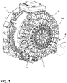
FIG. 1 is a perspective view of a direct drive motor for a laundry appliance attached to an outer drum, and shown with the outer cabinet removed; -
FIG. 2 is an elevational view of the direct drive motor ofFIG. 1 ; -
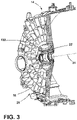
FIG. 3 is a cross-sectional view of the structural tub ofFIG. 1 , with the electric motor removed and showing an aspect of a metallic hub molded within the back wall of the tub; -
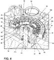
FIG. 4 is a cross-sectional view of the electric motor ofFIG. 2 taken along line IV-IV; -
FIG. 5 is an enlarged cross-sectional view of the direct drive motor ofFIG. 2 taken along line V-V; -
FIG. 6 is a perspective view of an aspect of the stator for the electric motor; -
FIG. 7 is a cross-sectional view of the stator ofFIG. 6 , taken along line VII-VII; -
FIG. 8 is a cross-sectional view of the stator ofFIG. 6 , taken along line VIII-VIII; -
FIG. 9 is a cross sectional view of the stator ofFIG. 6 , taken along line IX-IX; -
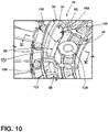
FIG. 10 is a perspective view of an aspect of a fastening portion of the stator ofFIG. 6 ; -
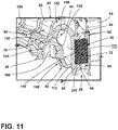
FIG. 11 is a cross-sectional view of the stator fastening portion ofFIG. 10 taken along line XI-XI; -
FIG. 12 is a cross-sectional view of the stator ofFIG. 7 taken through a first radial structure; -
FIG. 13 is a cross-sectional view of the stator ofFIG. 7 taken through a second radial structure; -
FIG. 14 is a perspective view of an aspect of a stator for the electric motor and including axial reinforcing walls; -
FIG. 15 is a cross-sectional view of the stator ofFIG. 14 taken along line XV-XV; -
FIG. 16 is a cross-sectional view of the stator ofFIG. 14 taken along line XVI-XVI; -
FIG. 17 is a cross-sectional view of the stator ofFIG. 14 taken along line XVII-XVII, and showing a schematic of the undulating reinforcing structure of the bridge section; -
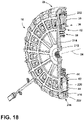
FIG. 18 is a cross-sectional view of the stator and rotor for an aspect of the electric motor; -
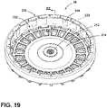
FIG. 19 is a perspective view of an aspect of the rotor for an electric motor; -
FIG. 20 is a cross-sectional view of the rotor ofFIG. 20 taken along line XXI-XXI; and -
FIG. 21 is a linear flow diagram illustrating a method for forming a stator for an electric motor. - The components in the figures are not necessarily to scale, emphasis instead being placed upon illustrating the principles described herein.
- The present illustrated embodiments reside primarily in combinations of method steps and apparatus components related to an electric motor for a laundry appliance having an overmold with an outer core section, a fastening interior section and a bridge section extending therebetween. Accordingly, the apparatus components and method steps have been represented, where appropriate, by conventional symbols in the drawings, showing only those specific details that are pertinent to understanding the embodiments of the present disclosure so as not to obscure the disclosure with details that will be readily apparent to those of ordinary skill in the art having the benefit of the description herein. Further, like numerals in the description and drawings represent like elements.
- For purposes of description herein, the terms "upper," "lower," "right," "left," "rear," "front," "vertical," "horizontal," and derivatives thereof shall relate to the disclosure as oriented in
FIG. 1 . Unless stated otherwise, the term "front" shall refer to the surface of the element closer to an intended viewer, and the term "rear" shall refer to the surface of the element further from the intended viewer. However, it is to be understood that the disclosure may assume various alternative orientations, except where expressly specified to the contrary. It is also to be understood that the specific devices and processes illustrated in the attached drawings, and described in the following specification are simply exemplary embodiments of the inventive concepts defined in the appended claims. Hence, specific dimensions and other physical characteristics relating to the embodiments disclosed herein are not to be considered as limiting, unless the claims expressly state otherwise. - The terms "including," "comprises," "comprising," or any other variation thereof, are intended to cover a non-exclusive inclusion, such that a process, method, article, or apparatus that comprises a list of elements does not include only those elements but may include other elements not expressly listed or inherent to such process, method, article, or apparatus. An element proceeded by "comprises a . . . " does not, without more constraints, preclude the existence of additional identical elements in the process, method, article, or apparatus that comprises the element.
- With respect to
FIGS. 1-5 ,reference numeral 10 generally refers to an electric motor for anappliance 12, typically alaundry appliance 12. Theelectric motor 10 is used to rotate certain components of thelaundry appliance 12, such as a rotatingdrum 14, an agitator, an impeller, and other rotationally operable components when theelectric motor 10 is in a direct-drive configuration 16. Anelectric motor 10 can also be in a belt-drive configuration (shown in dashed line inFIGS. 1 and2 ). In the belt-drive configuration, theelectric motor 10 can be used for operating the rotatingdrum 14, an impeller or agitator, a fluid pump, a blower and other similar rotational components. Typically, theelectric motor 10 described herein will be used in a direct drive configuration and attached to aback wall 18 of astructural tub 20. - Referring again to
FIGS. 1-13 , theelectric motor 10 for theappliance 12 can be attached to theback wall 18 of thetub 20. A structuralmetallic hub 22 is insert injection molded within theback wall 18 of thetub 20 to define arotational axis 24. Adrum 14 is rotationally operable within thetub 20 along therotational axis 24. Thestator 26 for theelectric motor 10 is attached to themetallic hub 22, and arotor 28 rotationally operates relative to thestator 26 and therotational axis 24. Typically, therotor 28 rotates around an outside of thestator 26. In certain configurations, therotor 28 can rotate within therotor 28 or both inside and outside of thestator 26. As exemplified herein, therotor 28 rotates about thestator 26 and about therotational axis 24 that extends through thetub 20, themetallic hub 22, thestator 26, and thedrum 14. Thestator 26 includes anannular core 30 that is made up of alaminated structure 32. Anovermold 34 extends around thecore 30. Theovermold 34 also extends inward of the core 30 tofastening portions 36 that are located within aninterior section 38 of theovermold 34 that is located within acentral area 40 defined by theannular core 30. Abridge section 42 of theovermold 34 extends from theinterior section 38 to at least one of an area of theovermold 34 above thecore 30 and an area of theovermold 34 below thecore 30. Accordingly, thebridge section 42 that extends from theinterior section 38 toward thecore 30 engages theovermold 34 surrounding thecore 30, referred to herein as thecore portion 240 of theovermold 34. In addition, thebridge section 42 engages thecore portion 240 in an area axially outside of the stackedlaminated structure 32 that forms theannular core 30. In this manner, thebridge section 42 defines atoroidal cavity 44 that extends between the core 30 and thefastening portions 36. Using this configuration, thebridge section 42 provides axial support between thefastening portions 36 and theannular core 30 such that vibration of thestator 26 is minimized during operation of theappliance 12. - According to various aspects of the device, the
laminated structure 32 of theannular core 30 can be in the form of a helically woundmetallic plate 60 that is spirally wound to form theannular core 30. Themetallic plate 60 that forms theannular core 30 can include ayoke 62 andteeth 64 that extend outwardly from theyoke 62, or inwardly in the case of inner-rotor configurations. As these laminations are helically or spirally wound to form theannular core 30, the stack of laminations that form thelaminated structure 32 can be attached viarivets 66 that extend through portions of thelaminated structure 32, and can also be welded together. In addition, various retainingtabs 68 can be stamped into the surface of themetallic plate 60 for joining the laminations together in the stacked configuration. When the helically woundmetallic plate 60 is formed into thelaminated structure 32, theannular core 30 forms a monolithic member that is formed through the helically or spirally woundmetallic plate 60. - Referring now to
FIGS. 7-13 , thebridge section 42 of thestator 26 can include afirst set 80 ofbridge portions 82 that extend from theinterior section 38 to an area proximate afirst face 84 of theannular core 30. Thebridge section 42 can also include asecond set 86 ofbridge portions 82 that extend from theinterior section 38 to an area proximate asecond face 88 of theannular core 30. The first and second faces 84, 88 of theannular core 30 are flat surfaces of theannular core 30 that oppose one another. The first and second faces 84, 88 also define the beginning and the ending of the helically or spirally woundmetallic plate 60 that forms theannular core 30. The first set 80 ofbridge portions 82 and second set 86 ofbridge portions 82 are typically positioned in an alternatingconfiguration 90 about theinterior section 38 and within thebridge section 42 of thestator 26. In addition, thetoroidal cavity 44 that extends between the core 30 andfastening portions 36 is formed between the first andsecond sets bridge portions 82. - The alternating
configuration 90 of the first andsecond sets bridge portions 82 is configured to allow for an injection molding process of theovermold 34 for thestator core 30 that uses a two-piece mold. This two-piece mold can form theovermold 34 for thestator 26 without the use of interior lifters. As discussed herein, the alternatingconfiguration 90 of the first andsecond sets bridge portions 82 provides structural integrity to thestator 26, and also provides for a more efficient forming process for theovermold 34 of thestator 26. - Referring again to
FIGS. 1-13 , thestator 26 for theelectric motor 10 can include theannular core 30 that is made up of a helical metal plate that is spirally wound into thelaminated structure 32. Theovermold 34 extends around thecore 30 and also defines theinterior section 38 and abridge section 42 that extends between the core 30 and theinterior section 38. Theinterior section 38 includesstator fastening portions 36 that are used to attach thestator 26 to the structuralmetallic hub 22 within thetub 20. Thebridge section 42 includes a firstradial structure 100 that extends from theinterior section 38 to thecore 30. Thebridge section 42 also includes a secondradial structure 102 that extends from theinterior section 38 to thecore 30. Thecore 30, theinterior section 38 and the first and secondradial structures toroidal cavity 44 within thebridge section 42. - Referring again to
FIGS. 6-13 , thefirst set 80 ofbridge portions 82 can be included within the firstradial structure 100 and thesecond set 86 ofbridge portions 82 can be included within the secondradial structure 102. Accordingly, the first and secondradial structures interior section 38, around thetoroidal cavity 44, and engage theovermold 34 outside of an inward-facingsurface 110 of theannular core 30. Accordingly, thebridge section 42 of thestator 26 engages theovermold 34 of the core 30 at outeraxial portions 112 of theovermold 34. This configuration provides structural integrity to the attachment between the core 30 and theinterior section 38 to minimize vibrations, noise, and other unwanted frequency-type interference. - As discussed above, the first and
second sets bridge portions 82 can be spaced apart from one another to form an alternatingconfiguration 90. In this manner, thebridge section 42 defines formingapertures 120 that extend through the first and secondradial structures configuration 90 described herein. Stated another way, the formingapertures 120 in the firstradial structure 100 align with thesecond set 86 ofbridge portions 82 of the secondradial structure 102. Conversely, the formingapertures 120 in the secondradial structure 102 align with thefirst set 80 ofbridge portions 82 of the firstradial structure 100. Again, this configuration of the formingapertures 120 is included to provide for a two-piece forming tool that can be used to form theovermold 34 without the use of lifters, or substantially without the use of lifters, during the forming process. - Referring now to
FIGS. 1-5 and9-10 , theinterior section 38 of theovermold 34 can include thefastening portions 36 for attaching thestator 26 to themetallic hub 22. Themetallic hub 22 can includevarious bosses 130 that receivefasteners 132 that extend through thefastening portions 36 of thestator 26 and engage thehub 22 that is molded within theback wall 18 of thetub 20. Thefastening portions 36 of thestator 26 includecompression limiters 134 that are injection molded within thefastening portions 36 of theinterior section 38 during the forming process of thestator 26. Each of thecompression limiters 134 can include anouter wall 136 having an outwardly extendingperimetrical ridge 138 that engages theinterior section 38 of theovermold 34. - Within conventional stators, the compression limiting features included within fastener portions typically include a spring metal that is press fit into various apertures of the stator. This press fitting operating can suffer from inaccuracies, damage to the forming material, and other deficiencies. In addition, the spring metal used in these conventional configurations may have a depth that is different than the thickness of the fastener portions surrounding the spring metal. Such differences can result in deformation of the spring metal and/or the fastener portions of the conventional stator when fasteners are tightened to secure the conventional stator. Such deformation can result in damage to the conventional stator during installation and overtime.
- Referring again to
FIGS. 9-10 , using thecompression limiters 134 having the outwardly extendingperimetrical ridge 138, thecompression limiters 134 are insert injection molded within theovermold 34 of thestator 26. This provides for a precise locating feature of thecompression limiters 134. In addition, during the forming process of theovermold 34 for thestator 26, thecompression limiters 134 are used to form at least a portion of the forming cavity that receives the forming material and defines thefastening portions 36. The use of thecompression limiters 134 as part of the forming cavity ensures that thecompression limiters 134 at thefastening portions 36 of thestator 26 are thesame depth 150 as theovermold 34. Accordingly, stresses exerted upon thestator 26 while fastening thestator 26 to thebosses 130 of thehub 22 are directed through thecompression limiters 134 and not through the material of theovermold 34. - In addition, using the outwardly extending
perimetrical ridge 138 of thecompression limiters 134 ensures that thecompression limiters 134 will not slide or otherwise deflect in an axial direction with respect to thestator 26 or themetallic hub 22. The outwardly extendingperimetrical ridge 138 ensures a stable location of the location limiters with respect to theovermold 34. Accordingly, the fastening interface between thestator 26 and thehub 22 is a secure interface that helps to prevent deformation of theovermold 34 during the installation process of thestator 26. - Referring now to
FIGS. 14-18 , theappliance 12 includes thetub 20 and themetallic hub 22 that is molded within thetub 20 to define therotational axis 24. Thedrum 14 is rotationally operable within thetub 20 along therotational axis 24. Thestator 26 for theelectric motor 10 is attached to the structuralmetallic hub 22 and arotor 28 is rotationally operable relative to thestator 26. Thestator 26 includes theannular core 30 that is made up of thelaminated structure 32 that is typically formed from a helically or spirally woundmetallic plate 60. Theovermold 34 extends around thecore 30 and also extends into acentral area 40 of thecore 30. Fasteningportions 36 are located within thisinterior section 38 of theovermold 34 that is located within thecentral area 40 of thecore 30. Thebridge section 42 of theovermold 34 extends between theinterior section 38 and thecore 30. Thebridge section 42 includes the firstradial structure 100 and the secondradial structure 102. In certain aspects of the device, thebridge section 42 can also include a reinforcing portion that provides additional axial support within thebridge section 42. This reinforcing portion can be in the form of anaxial reinforcement 160. - In certain aspects of the device, the first
radial structure 100, theaxial reinforcement 160 and the secondradial structure 102 cooperate to define an undulating reinforcingstructure 170 that extends between theinterior section 38 and thecore 30. Stated another way, the firstradial structure 100 extends from theinterior section 38 and engages theovermold 34 of thecore 30 outside of thefirst face 84 of thecore 30. The secondradial structure 102 extends from theinterior section 38 and engages theovermold 34 outside of asecond face 88 of thecore 30. As discussed herein, theinner surface 172 of thecore 30 and the first and secondradial structures toroidal cavity 44 that extends between the core 30 andinterior section 38 of thestator 26. Theaxial reinforcement 160 forms a portion of thebridge section 42 and extends between the first and secondradial structures radial structure 100, the secondradial structure 102 and theaxial reinforcement 160 form the undulating reinforcingstructure 170 of thestator 26. - In certain aspects of the device, the
axial reinforcement 160 can be located atedges 180 of the formingapertures 120 that are alternately positioned within the firstradial structure 100 and the secondradial structure 102. Accordingly, thefirst set 80 ofbridge portions 82 of the firstradial structure 100 and thesecond set 86 ofbridge portions 82 of the secondradial structure 102 can be connected together using theaxial reinforcements 160. Theaxial reinforcements 160 can be used to at least partially divide thetoroidal cavity 44 into various arcuate reinforcingsections 182 of thebridge section 42. Theaxial reinforcement 160 can extend the full distance between the core 30 and theinterior section 38 of thestator 26. In certain aspects, theaxial reinforcement 160 can extend only a portion of the way between the core 30 and theinterior section 38. In such a configuration, thetoroidal cavity 44 is a continuous space that extends between theinterior section 38 and thecore 30. - In the various aspects of the device, as exemplified in
FIGS. 1-18 , theaxial reinforcement 160 can be utilized in certain designs of thestator 26 that may require reinforcement at certain operational frequencies of aparticular appliance 12. In addition, the exact configuration of theaxial reinforcement 160 can vary depending upon the exact design of thestator 26 and the design of theappliance 12. It is contemplated that theaxial reinforcements 160 can be utilized for fully dividing sections of thetoroidal cavity 44 such that theaxial reinforcement 160 defines a wall that extends between the core 30 and theinterior section 38 of theovermold 34 for thestator 26. - Referring again to
FIGS. 7-18 , theindividual bridge portions 82 that are positioned within the first and secondradial structures first set 80 ofbridge portions 82 and thesecond set 86 ofbridge portions 82 have a consistent arcuate length throughout thebridge section 42 of thestator 26. It is also contemplated that thefirst set 80 ofbridge portions 82 and thesecond set 86 ofbridge portions 82 can have different sizes. In addition, thefirst set 80 ofbridge portions 82 and thesecond set 86 ofbridge portions 82 can includeradial reinforcements 190 that extend outside thetoroidal cavity 44 between theinterior section 38 and thecore 30. Theseradial reinforcements 190 can vary in number and size depending upon the configuration of thestator 26 that is to be placed within aparticular appliance 12. In addition, theseradial reinforcements 190 can extend continuously from theinterior section 38 to areas outside the first and second faces 84, 88 of theannular core 30. - Referring now to
FIGS. 1-5 and19-21 , therotor 28 for theelectric motor 10 is configured to rotationally operate about thestator 26 to define an electromotive force that drives adrive shaft 210 for rotating arotating drum 14 positioned within thetub 20. Therotor 28 includes a centralmetallic coupler 212 that engages thedrive shaft 210 and attaches to thebody 214 of therotor 28. Thebody 214 of therotor 28 is typically made of a bulk molding compound that is molded over thecentral coupler 212. Therotor 28 also includes a plurality ofmagnets 216 positioned at anouter wall 218 of therotor 28. Thesemagnets 216 interact with thewindings 220 of thestator 26 to define the electromotive force that rotates therotor 28 about thestator 26. Themagnets 216 are included within the bulk molding compound that forms thebody 214 of therotor 28. According to various aspects of the device, the material of therotor 28 can include any one of various molding materials. These materials can include, but are not limited to, bulk molding compounds, polypropylene, composite materials, and other polymer materials. Therotor 28 can also include a metallic plate that is used as the main structure of therotor 28 or is formed with one or more polymer materials or bulk molding compounds to form a composite structure of therotor 28. - Referring again to
FIGS. 1-5 and19-21 , ametallic back iron 222 is positioned proximate themagnets 216 of therotor 28 and is typically made of a metallic material such as steel. In forming theback iron 222 of therotor 28, aband 224 of steel can be wound or wrapped around the plurality ofmagnets 216 to form theback iron 222. The wrappedband 224 of steel that forms theback iron 222 is wound such that thewidth 228 of theband 224 is also thewidth 228 of the completed backiron 222. Layering theband 224 of steel increases thecross-sectional thickness 230 of theback iron 222. This process ensures aconsistent thickness 230 of theback iron 222. Theback iron 222 that is made up of the wrappedband 224 of steel provides proficiency in concentrating magnetic flux toward aninner portion 232 of therotor 28. This serves to efficiently generate the electromotive force that is defined between themagnets 216 of therotor 28 and the energizedwindings 220 of thestator 26. This configuration of theback iron 222 directs the magnetic flux toward the energizedwindings 220 of thestator 26 during operation of theelectric motor 10. In various aspects of the device, it is contemplated that theback iron 222 can be a segmented back iron formed from a plurality of arcuate sections. Other configurations of theback iron 222 are also contemplated. These configurations can include, but are not limited to, laminated backiron 222, a steel can backiron 222 and other similar configurations. - Referring now to
FIGS. 1 -22, having described various aspects of theelectric motor 10, amethod 400 is disclosed for forming astator 26 for theelectric motor 10. According to themethod 400, theannular core 30 andcompression limiters 134 are placed into a forming cavity of a two-piece forming tool (step 402). The forming tool is closed to form the forming cavity, where the forming cavity is also defined by the outer surface of thecore 30 and theouter wall 136 and outwardly extendingperimetrical ridge 138 of the compression limiters 134 (step 404). The two-piece forming tool that forms the forming cavity is operated without the use of lifters. Accordingly, the two-piece forming tool includes an upper half and a lower half that form the interior cavity into which the forming material is injected. According to themethod 400, the molding material is injected into the forming cavity to form around thecore 30 and the compression limiters 134 (step 406). The forming tool is then separated and the formedstator 26 is removed from the forming cavity (step 408). As discussed herein, the forming tool operates without the use of lifters to form the structure of thestator 26. The structure of thestator 26 includes abridge section 42 having an undulating reinforcingstructure 170 that extends between thecompression limiters 134 and the core 30 (step 408). In addition, using thismethod 400, thetoroidal cavity 44 of thebridge section 42 can be formed between theinterior section 38 of theovermold 34 and the portion of thecore portion 240 of theovermold 34 that extends around thecore 30. Using this configuration, thetoroidal cavity 44 can help to provideaxial reinforcement 160 between thefastening portions 36 of thestator 26 and thecore 30 of thestator 26. This serves to minimize noise, vibration, and other undesirable frequencies within thestator 26 during operation of theappliance 12. - According to various aspects of the device, the
bridge section 42 of theovermold 34 can extend from theinterior section 38 to thecore portion 240 of theovermold 34 extending around theannular core 30. In certain aspects of the device, thebridge section 42 can include only one of the firstradial structure 100 and the secondradial structure 102. In such an aspect of the device, thebridge section 42 can include various formingapertures 120 that are positioned within thebridge section 42. Typically, these formingapertures 120 are positioned near thefastening portions 36 of thestator 26 within theinterior section 38 of theovermold 34. These apertures can be used during the forming process to avoid molding steel that may be set within theovermold 34 for thestator 26. - By way of example and not limitation, the
stator 26 for theelectric motor 10 can include (27)teeth 64 that extend around theyoke 62 of theannular core 30. After being overmolded, winding wires are wound around thevarious teeth 64 to formpoles 250 of thestator 26 that can be energized in certain configurations to interact with themagnets 216 of therotor 28 and provide varying degrees of electromotive force for rotating therotor 28 about thestator 26. In an exemplary and non-limiting aspect of the device, therotor 28 can include (24)magnets 216. It should be understood that the number ofteeth 64 of thestator 26, the number ofpoles 250, and the number ofmagnets 216 can vary depending on the design of theelectric motor 10 and theappliance 12. - Referring again to
FIGS. 1-18 , theovermold 34 of thestator 26 can includevarious connections 260. These connections can include a receptacle for receiving a harness that connects with a three-phase jumper that is integrally formed within theovermold 34 of thestator 26. In this location, according to various aspects of the device, the three wires can be attached to asingle connector 260 where the wires are coupled together and crimped to or otherwise coupled to form a short bar location that is used to prevent short circuit events with respect to thestator 26. Theconnections 260 can also include power connections where three dedicated connectors can be coupled to the three wires of the three-phase windings 220 of thestator 26. Theseconnections 260 are integrally formed into theovermold 34 so that the various wires can be securely and consistently connected to the various connectors that engage thestator 26. The wires that form thewindings 220 that are wound around theteeth 64 can be extended to theseconnections 260 such that an electrical connection between a controller, inverter or other similar electrical interface can be connected directly to thestator 26. Using theseconnections 260 that are injection molded within theovermold 34 of thestator 26, a sealer is typically not used for attaching the harness to theharness connection 260 of thestator 26. Theseconnections 260 of thestator 26 can include one or more connection for each phase for thewindings 220 for thestator 26, as well as a ground connection. In addition, thevarious connections 260 can include one or more data interface locations for receiving certain positioning information relating to the position of therotor 28 with respect to thestator 26. Accordingly, various Hall effect sensors, rotational sensors, positioning sensors, and other similar configurations can be included within thestator 26. It is also contemplated that the positioning interface between thestator 26 and therotor 28 can be a sensorless configuration. - According to another aspect of the present disclosure, an electric motor for an appliance includes a tub. A metallic hub is molded within the tub to define a rotational axis. A drum is rotationally operable within the tub along the rotational axis. A stator is attached to the metallic hub and a rotor rotationally operates about the stator. The stator includes an annular core made up of a laminated structure. An overmold extends around the core. Fastening portions are located within an interior section of the overmold that is located within a central area of the core. A bridge section of the overmold extends from the interior section to at least one of an area above the core and an area below the core. The bridge section defines a toroidal cavity that extends between the core and the fastening portions.
- According to another aspect, the laminated structure includes a helically wound metallic plate.
- According to yet another aspect, the bridge section include a first set of bridge portions that extend from the interior section to an area below the core. The bridge section includes a second set of bridge portions that extend from the interior section to an area above the core. The first set of bridge portions and the second set of bridge portions are in an alternating configuration about the interior section.
- According to another aspect of the present disclosure, the overmold includes a reinforcing portion that at least partially divides the toroidal cavity into toroidal sections.
- According to another aspect, the reinforcing portion, the first set of bridge portions and the second set of bridge portions define an undulating reinforcing structure that extends between the core and the interior section.
- According to yet another aspect, the fastening portions of the stator include compression limiters that are injection molded within the interior section.
- According to another aspect of the present disclosure, each compression limiter includes an outer wall having an outwardly extending perimetrical ridge that engages the interior section of the overmold.
- According to another aspect, the rotor includes a plurality of magnets and a metallic back iron that extends around the magnets.
- According to yet another aspect, the metallic back iron includes a wrapped band of steel.
- According to another aspect of the present disclosure, the rotor includes a central coupler and a body that surrounds the coupler, the magnets and the back iron. The body includes a bulk molding compound.
- According to another aspect, a stator for an appliance motor includes an annular core made up of a metallic plate that is spirally wound into a laminated structure. An overmold extends around the core and further defines an interior section and a bridge section that extends between the core and the interior section. The interior section includes stator fastening portions that are used to attach the stator to a tub. The bridge section includes a first radial structure that extends from the interior section to the core. The bridge section includes a second radial structure that extends from the interior section to the core. The core, the interior section and the first and second radial structures define a toroidal cavity within the bridge section.
- According to yet another aspect, the bridge section defines forming apertures that extend through the first and second radial structures in an alternating configuration.
- According to another aspect of the present disclosure, the bridge section further includes axial reinforcements that extend between the first and second radial structures.
- According to another aspect, the axial reinforcements and the first and second radial structures define an undulating reinforcing structure of the bridge section.
- According to yet another aspect, each of the fastening portions includes a comprising compression limiter having an outer wall with an outwardly extending perimetrical ridge that engages the interior section of the overmold.
- According to another aspect of the present disclosure, the compression limiters and the annular core are insert injection molded within the overmold.
- According to another aspect, an electric motor for an appliance includes a tub. A metallic hub is molded within the tub to define a rotational axis. A drum is rotationally operable within the tub along the rotational axis. A stator is attached to the metallic hub and a rotor rotationally operates about the stator. The stator includes an annular core made up of a laminated structure. An overmold extends around the core and extends into a central area of the core. Fastening portions are located within an interior section of the overmold that is located within the central area of the core. A bridge section of the overmold extends from the interior section to the core. The bridge section includes a first radial structure, a second radial structure and an axial reinforcement. The first radial structure, the axial reinforcement and the second radial structure defines an undulating reinforcing structure that extends between the interior section and the core.
- According to yet another aspect, the core, the interior section and the first and second radial structures define a toroidal cavity within the bridge section.
- According to another aspect of the present disclosure, the axial reinforcements at least partially divide the toroidal cavity into arcuate reinforcing sections of the bridge section.
- According to another aspect, the rotor includes a plurality of magnets and a metallic back iron that extends around the magnets. The metallic back iron includes a wrapped band of steel.
Claims (15)
- An electric motor (10) for an appliance (12) comprising:a stator (26);a rotor (28) that rotationally operates about the stator (26);the stator (26) comprising:an annular core (30) made up of a laminated structure (32);an overmold (34) that extends around the core (30);fastening portions (36) located within an interior section (38) of the overmold (34) that is located within a central area (40) of the core (30); anda bridge section (42) of the overmold (34) that extends from the interior section (38) to at least one of an area above the core (30) and an area below the core (30), the bridge section (42) defining a toroidal cavity (44) that extends between the core (30) and the fastening portions (36).
- The electric motor (10) of claim 1, wherein the laminated structure (32) includes a helically wound metallic plate (60).
- The electric motor (10) of any one of claims 1-2, wherein the bridge section (42) includes a first set of bridge portions (82) that extend from the interior section (38) to an area below the core (30).
- The electric motor (10) of any one of claims 1-3, wherein the bridge section (42) includes a first radial structure (100) that extends from the interior section (38) to an area of the overmold (34) that is below the core (30), and wherein the bridge section (42) includes a second radial structure (102) that extends from the interior section (38) to an area of the overmold (34) that is above the core (30).
- The electric motor (10) of claim 4, wherein the first radial structure (100) and the second radial structure (102) of bridge section (42) are positioned in an alternating configuration (90) about the interior section (38).
- The electric motor (10) of any one of claims 4-5, wherein the overmold (34) includes a reinforcing portion that at least partially divides the toroidal cavity (44) into toroidal sections.
- The electric motor (10) of claim 6, wherein the reinforcing portion, the first radial structure (100) and the second radial structure (102) define an undulating reinforcing structure (170) which runs in an undulating configuration throughout the bridge section (42) and extends between the core (30) and the interior section (38).
- The electric motor (10) of any one of claims 1-7, wherein the fastening portions (36) of the stator (26) include compression limiters (134) that are injection molded within the interior section (38).
- The electric motor (10) of claim 8, wherein each compression limiter (134) includes an outer wall (136) having a ridge that engages the interior section (38) of the overmold (34).
- The electric motor (10) of claim 9, wherein the ridge of the outer wall (136) defines an outwardly extending perimetrical ridge (138) that engages the interior section (38) of the overmold (34).
- The electric motor (10) of any one of claims 1-10, wherein the rotor (28) includes a plurality of magnets (216) and a metallic back iron (222) that extends around the magnets (216).
- The electric motor (10) of claim 11, wherein the metallic back iron (222) includes a wrapped band (224) of steel.
- The electric motor (10) of any one of claims 11-12, wherein the rotor (28) includes a central coupler (212) and a body (214) that surrounds the coupler (212), the magnets (216) and the back iron (222), wherein the body (214) includes a bulk molding compound.
- A laundry appliance comprisinga tub (20);a metallic hub (22) molded within the tub (20) to define a rotational axis (24);a drum (14) that is rotationally operable within the tub (20) along the rotational axis (24); andan electric motor (10) according to any of the previous claims.
- The laundry appliance of claim 14, wherein the stator (26) is attached to the metallic hub (22).
Applications Claiming Priority (1)
| Application Number | Priority Date | Filing Date | Title |
|---|---|---|---|
| US17/204,989 US11750046B2 (en) | 2021-03-18 | 2021-03-18 | Electric motor for an appliance |
Publications (1)
| Publication Number | Publication Date |
|---|---|
| EP4068586A1 true EP4068586A1 (en) | 2022-10-05 |
Family
ID=80819806
Family Applications (1)
| Application Number | Title | Priority Date | Filing Date |
|---|---|---|---|
| EP22162844.9A Withdrawn EP4068586A1 (en) | 2021-03-18 | 2022-03-17 | Electric motor for an appliance |
Country Status (3)
| Country | Link |
|---|---|
| US (1) | US11750046B2 (en) |
| EP (1) | EP4068586A1 (en) |
| CN (1) | CN115173627A (en) |
Citations (7)
| Publication number | Priority date | Publication date | Assignee | Title |
|---|---|---|---|---|
| US20070163306A1 (en) * | 2005-11-30 | 2007-07-19 | Lg Electronics Inc. | Washing machine |
| KR20080076056A (en) * | 2007-02-14 | 2008-08-20 | 엘지전자 주식회사 | Drum Washing Machine |
| KR101033570B1 (en) * | 2004-02-26 | 2011-05-11 | 엘지전자 주식회사 | Stator structure of outer rotor type motor for drum washing machine |
| US20130009513A1 (en) * | 2011-07-07 | 2013-01-10 | New Motech Co., Ltd. | Stator assembly for motor |
| US20130214637A1 (en) * | 2011-12-05 | 2013-08-22 | Fisher & Paykel Appliances Ltd. | Electrical machine |
| US8567043B2 (en) * | 2009-12-14 | 2013-10-29 | Nidec Motor Corporation | Method of assembling low noise rotor or stator of an electric motor or generator |
| US9000639B2 (en) * | 2011-12-06 | 2015-04-07 | Nidec Motor Corporation | Mounting cap for insulated stator of outer rotor motor |
Family Cites Families (22)
| Publication number | Priority date | Publication date | Assignee | Title |
|---|---|---|---|---|
| US5145329A (en) * | 1990-06-29 | 1992-09-08 | Eaton Corporation | Homoplanar brushless electric gerotor |
| EP1516418B1 (en) | 2002-06-26 | 2011-03-23 | Amotech Co., Ltd. | Brushless direct-current motor of radial core type having a structure of double rotors |
| KR100484817B1 (en) * | 2002-10-10 | 2005-04-22 | 엘지전자 주식회사 | Manufacturing structure of core for washing machine motor |
| KR100595192B1 (en) * | 2003-11-06 | 2006-06-30 | 엘지전자 주식회사 | Driving part structure of drum washing machine |
| AU2004237798B2 (en) | 2003-12-10 | 2010-06-24 | Lg Electronics Inc. | Outer type motor for drum type washing machine and method for fabricating the same |
| KR100564442B1 (en) | 2003-12-10 | 2006-03-29 | 엘지전자 주식회사 | Top Loading Drum Washing Machine |
| KR100565652B1 (en) | 2003-12-30 | 2006-03-30 | 엘지전자 주식회사 | driving unit in top loading drum type washing machine |
| EP1810387B1 (en) | 2004-11-09 | 2013-06-26 | LG Electronics Inc. | Direct drive motor in washing machine |
| KR101141638B1 (en) | 2004-11-11 | 2012-05-04 | 엘지전자 주식회사 | direct drive motor in washing machine |
| KR101208502B1 (en) | 2005-11-08 | 2012-12-10 | 엘지전자 주식회사 | Motor for direct drive type washing machine |
| KR100808194B1 (en) | 2006-05-19 | 2008-02-29 | 엘지전자 주식회사 | Stator of outer rotor type motor |
| WO2007148920A2 (en) | 2006-06-21 | 2007-12-27 | Lg Electronics Inc. | Stator of motor and washing machine having the same |
| KR100890891B1 (en) | 2007-04-10 | 2009-04-02 | 주식회사 아모텍 | Driving device for washing machine and automatic washing machine using same |
| KR101460133B1 (en) | 2009-08-17 | 2014-11-11 | 삼성전자 주식회사 | A motor for a washing machine and a washing machine having the same |
| WO2011144539A1 (en) * | 2010-05-20 | 2011-11-24 | Arcelik Anonim Sirketi | A washing machine wherein the unbalanced load is balanced |
| KR101130978B1 (en) | 2010-06-23 | 2012-03-28 | 주식회사 아모텍 | Slim type stator and method of making the same, slim type motor having the stator, and direct drive apparatus for drum-washing machine |
| US8344568B2 (en) | 2010-08-17 | 2013-01-01 | Nidec Motor Corporation | Direct drive rotor with metal coupler |
| DE202011111030U1 (en) | 2010-12-22 | 2018-07-05 | Fisher & Paykel Appliances Limited | improved device, motor or stator |
| KR101317892B1 (en) | 2011-01-24 | 2013-10-16 | 주식회사 아모텍 | Amorphous Stator and Producing Method thereof |
| US8946954B2 (en) | 2012-04-20 | 2015-02-03 | Nidec Motor Corporation | Integrated direct drive motor and control |
| CN104884699B (en) | 2012-12-18 | 2017-02-15 | 阿莫泰克有限公司 | Driving device for washing machine and washing machine with same |
| KR101604902B1 (en) | 2014-04-01 | 2016-03-22 | 뉴모텍(주) | Stator of Motor for Washing Machine |
-
2021
- 2021-03-18 US US17/204,989 patent/US11750046B2/en active Active
-
2022
- 2022-03-17 EP EP22162844.9A patent/EP4068586A1/en not_active Withdrawn
- 2022-03-18 CN CN202210272269.XA patent/CN115173627A/en active Pending
Patent Citations (7)
| Publication number | Priority date | Publication date | Assignee | Title |
|---|---|---|---|---|
| KR101033570B1 (en) * | 2004-02-26 | 2011-05-11 | 엘지전자 주식회사 | Stator structure of outer rotor type motor for drum washing machine |
| US20070163306A1 (en) * | 2005-11-30 | 2007-07-19 | Lg Electronics Inc. | Washing machine |
| KR20080076056A (en) * | 2007-02-14 | 2008-08-20 | 엘지전자 주식회사 | Drum Washing Machine |
| US8567043B2 (en) * | 2009-12-14 | 2013-10-29 | Nidec Motor Corporation | Method of assembling low noise rotor or stator of an electric motor or generator |
| US20130009513A1 (en) * | 2011-07-07 | 2013-01-10 | New Motech Co., Ltd. | Stator assembly for motor |
| US20130214637A1 (en) * | 2011-12-05 | 2013-08-22 | Fisher & Paykel Appliances Ltd. | Electrical machine |
| US9000639B2 (en) * | 2011-12-06 | 2015-04-07 | Nidec Motor Corporation | Mounting cap for insulated stator of outer rotor motor |
Also Published As
| Publication number | Publication date |
|---|---|
| CN115173627A (en) | 2022-10-11 |
| US11750046B2 (en) | 2023-09-05 |
| US20220302772A1 (en) | 2022-09-22 |
Similar Documents
| Publication | Publication Date | Title |
|---|---|---|
| US12031260B2 (en) | Reinforcing cap for a tub rear wall of an appliance | |
| EP2053721A2 (en) | Rotating machine | |
| EP2012409A2 (en) | Rotating electrical machine | |
| US10439453B2 (en) | Stator | |
| US20130057105A1 (en) | Permanent magnet motors and methods of assembling the same | |
| US20150061441A1 (en) | Electric machine and associated method | |
| JPH05115141A (en) | Slotless motor | |
| JP2002112476A (en) | Permanent magnet type rotating electric machine | |
| EP1000454A1 (en) | Electric motor of the electronic commutation type for applications with a feeder line | |
| JPH11356019A (en) | Rotating electric machine rotor | |
| KR20100084939A (en) | Axial type motor | |
| US20080061649A1 (en) | Axial gap motor and method for manufacturing the same | |
| JP2004096874A (en) | Flat f permanent magnet dynano electric machine | |
| EP4622064A1 (en) | Synchronous reluctance motor having a ferrite assisted reluctance rotor | |
| CN218514264U (en) | Axial flux motor for washing machine | |
| EP0909477B1 (en) | Electronically commutated motor for direct drive of washing machine drum | |
| US20130057107A1 (en) | Permanent magnet motors and methods of assembling the same | |
| US11750046B2 (en) | Electric motor for an appliance | |
| WO2007132768A1 (en) | Motor | |
| KR102694355B1 (en) | Stator for Axial Gap Type Electric Motor and Manufacturing Method thereof | |
| KR102750997B1 (en) | Axial Gap Type Electric Motor for Electric Water Pump | |
| EP3780341A1 (en) | Electric motor | |
| JP2000333391A (en) | Permanent magnet type rotating electric machine | |
| US20130057104A1 (en) | Permanent magnet motors and methods of assembling the same | |
| US20240055923A1 (en) | Synchronous reluctance motor having a stator with stacked laminations and a method of construction |
Legal Events
| Date | Code | Title | Description |
|---|---|---|---|
| PUAI | Public reference made under article 153(3) epc to a published international application that has entered the european phase |
Free format text: ORIGINAL CODE: 0009012 |
|
| STAA | Information on the status of an ep patent application or granted ep patent |
Free format text: STATUS: THE APPLICATION HAS BEEN PUBLISHED |
|
| AK | Designated contracting states |
Kind code of ref document: A1 Designated state(s): AL AT BE BG CH CY CZ DE DK EE ES FI FR GB GR HR HU IE IS IT LI LT LU LV MC MK MT NL NO PL PT RO RS SE SI SK SM TR |
|
| RAP3 | Party data changed (applicant data changed or rights of an application transferred) |
Owner name: WHIRLPOOL CORPORATION |
|
| STAA | Information on the status of an ep patent application or granted ep patent |
Free format text: STATUS: REQUEST FOR EXAMINATION WAS MADE |
|
| 17P | Request for examination filed |
Effective date: 20230405 |
|
| RBV | Designated contracting states (corrected) |
Designated state(s): AL AT BE BG CH CY CZ DE DK EE ES FI FR GB GR HR HU IE IS IT LI LT LU LV MC MK MT NL NO PL PT RO RS SE SI SK SM TR |
|
| STAA | Information on the status of an ep patent application or granted ep patent |
Free format text: STATUS: THE APPLICATION IS DEEMED TO BE WITHDRAWN |
|
| 18D | Application deemed to be withdrawn |
Effective date: 20241001 |