EP4068545A1 - Earth leakage detecting device, and vehicular power supply system - Google Patents
Earth leakage detecting device, and vehicular power supply system Download PDFInfo
- Publication number
- EP4068545A1 EP4068545A1 EP20894879.4A EP20894879A EP4068545A1 EP 4068545 A1 EP4068545 A1 EP 4068545A1 EP 20894879 A EP20894879 A EP 20894879A EP 4068545 A1 EP4068545 A1 EP 4068545A1
- Authority
- EP
- European Patent Office
- Prior art keywords
- voltage
- state
- resistance
- detecting device
- leakage detecting
- Prior art date
- Legal status (The legal status is an assumption and is not a legal conclusion. Google has not performed a legal analysis and makes no representation as to the accuracy of the status listed.)
- Granted
Links
Images



Classifications
-
- G—PHYSICS
- G01—MEASURING; TESTING
- G01R—MEASURING ELECTRIC VARIABLES; MEASURING MAGNETIC VARIABLES
- G01R31/00—Arrangements for testing electric properties; Arrangements for locating electric faults; Arrangements for electrical testing characterised by what is being tested not provided for elsewhere
- G01R31/50—Testing of electric apparatus, lines, cables or components for short-circuits, continuity, leakage current or incorrect line connections
- G01R31/52—Testing for short-circuits, leakage current or ground faults
-
- B—PERFORMING OPERATIONS; TRANSPORTING
- B60—VEHICLES IN GENERAL
- B60L—PROPULSION OF ELECTRICALLY-PROPELLED VEHICLES; SUPPLYING ELECTRIC POWER FOR AUXILIARY EQUIPMENT OF ELECTRICALLY-PROPELLED VEHICLES; ELECTRODYNAMIC BRAKE SYSTEMS FOR VEHICLES IN GENERAL; MAGNETIC SUSPENSION OR LEVITATION FOR VEHICLES; MONITORING OPERATING VARIABLES OF ELECTRICALLY-PROPELLED VEHICLES; ELECTRIC SAFETY DEVICES FOR ELECTRICALLY-PROPELLED VEHICLES
- B60L3/00—Electric devices on electrically-propelled vehicles for safety purposes; Monitoring operating variables, e.g. speed, deceleration or energy consumption
- B60L3/0023—Detecting, eliminating, remedying or compensating for drive train abnormalities, e.g. failures within the drive train
- B60L3/0069—Detecting, eliminating, remedying or compensating for drive train abnormalities, e.g. failures within the drive train relating to the isolation, e.g. ground fault or leak current
-
- G—PHYSICS
- G01—MEASURING; TESTING
- G01R—MEASURING ELECTRIC VARIABLES; MEASURING MAGNETIC VARIABLES
- G01R35/00—Testing or calibrating of apparatus covered by the other groups of this subclass
-
- H—ELECTRICITY
- H02—GENERATION; CONVERSION OR DISTRIBUTION OF ELECTRIC POWER
- H02H—EMERGENCY PROTECTIVE CIRCUIT ARRANGEMENTS
- H02H3/00—Emergency protective circuit arrangements for automatic disconnection directly responsive to an undesired change from normal electric working condition with or without subsequent reconnection ; integrated protection
- H02H3/02—Details
- H02H3/04—Details with warning or supervision in addition to disconnection, e.g. for indicating that protective apparatus has functioned
- H02H3/044—Checking correct functioning of protective arrangements, e.g. by simulating a fault
-
- H—ELECTRICITY
- H02—GENERATION; CONVERSION OR DISTRIBUTION OF ELECTRIC POWER
- H02H—EMERGENCY PROTECTIVE CIRCUIT ARRANGEMENTS
- H02H3/00—Emergency protective circuit arrangements for automatic disconnection directly responsive to an undesired change from normal electric working condition with or without subsequent reconnection ; integrated protection
- H02H3/16—Emergency protective circuit arrangements for automatic disconnection directly responsive to an undesired change from normal electric working condition with or without subsequent reconnection ; integrated protection responsive to fault current to earth, frame or mass
- H02H3/17—Emergency protective circuit arrangements for automatic disconnection directly responsive to an undesired change from normal electric working condition with or without subsequent reconnection ; integrated protection responsive to fault current to earth, frame or mass by means of an auxiliary voltage injected into the installation to be protected
Definitions
- the present invention relates to a leakage detecting device that detects a current leakage from a load insulated from a ground, and to a vehicular power supply system.
- Hybrid vehicles HV
- plug-in hybrid vehicles PSV
- electric vehicles EV
- auxiliary batteries which are, in general, lead batteries with power output of 12 V
- drive batteries for high-voltage use traction batteries
- a high-voltage circuit including a drive battery for high voltage use, an inverter, and a running motor is insulated from the body (chassis ground) of a vehicle.
- a Y capacitor is provided between a positive line of the high-voltage circuit, the positive line being on a vehicle side, and the chassis ground and between a negative line of the high-voltage circuit, the negative line being on the vehicle side, and the chassis ground as well. This stabilizes power supply from the high-voltage drive battery to a load on the vehicle side.
- a leakage detecting device is incorporated in a vehicle to monitor insulation resistance between the high-voltage circuit and the chassis ground and detect a current leakage.
- a leakage detecting device of an AC type applies a pulse voltage to a positive-electrode terminal or a negative-electrode terminal of the drive battery via a resistance and a coupling capacitor, and measures a voltage at a node between the resistance and the coupling capacitor, thereby detecting the presence or absence of a current leakage.
- one of methods of diagnosing a failure of the leakage detecting device of the AC type is a method of applying a pulse voltage with a frequency sufficiently lower than the frequency of the pulse voltage for leak detection, comparing the applied voltage with a measured voltage, and determining that the device is in a normal state when both applied voltage and measured voltage are close to each other (see, for example, PTL 1).
- the present disclosure has been made in view of the above circumstance, and it is therefore an object of the present disclosure to provide a technique for highly precisely carrying out a failure diagnosis of a leakage detecting device.
- a leakage detecting device includes: a coupling capacitor in a state of being insulated from a ground, the coupling capacitor having one end connected to a current path of a power storage unit connected to a load; a first voltage output unit that generates a cyclic voltage that changes cyclically, the first voltage output unit applying the cyclic voltage to another end of the coupling capacitor via a first resistance; a second voltage output unit that outputs a fixed voltage; a second resistance and a third resistance that are connected in series between a node and the second voltage output unit, the node being between the coupling capacitor and the first resistance; a voltage measurement unit that measures a voltage at a voltage dividing point between the second resistance and the third resistance; a leakage determining unit that in a state of the cyclic voltage being outputted from the first voltage output unit, determines presence or absence of a current leakage between the current path of the power storage unit and the ground, based on a voltage measured by the
- a diagnosis of a failure of the leakage detecting device can be carried out highly precisely.
- Fig. 1 is a diagram for explaining a configuration of power supply system 5 including leakage detecting device 10 according to a comparative example.
- Power supply system 5 is incorporated in an electric vehicle. In the electric vehicle, power supply system 5 is provided in separation from an auxiliary battery (which is usually a lead battery with power output of 12 V).
- Power supply system 5 includes power storage unit 20 for high voltage use and leakage detecting device 10.
- Power storage unit 20 includes a plurality of cells E1 to En connected in series. Lithium ion battery cells, nickel metal hydride battery cells, lead battery cells, electric double-layer capacitor cells, lithium ion capacitor cells, or the like can be used as cells E1 to En.
- Lithium ion battery cells, nickel metal hydride battery cells, lead battery cells, electric double-layer capacitor cells, lithium ion capacitor cells, or the like can be used as cells E1 to En.
- lithium ion battery cells with a nominal voltage ranging from 3.6 V to 3.7 V
- the electric vehicle includes inverter 2 and motor 3 as loads for high voltage use.
- the positive electrode of power storage unit 20 is connected to one end of inverter 2 through positive line Lp, and the negative electrode of power storage unit 20 is connected to the other end of inverter 2 through negative line Lm.
- Positive line Lp is provided with positive-side main relay MRp, and negative line Lm is provided with negative-side main relay MRm.
- Positive-side main relay MRp and negative-side main relay MRm function as contactors that control electrical connection/disconnection between power storage unit 20 and the loads for high-voltage use in the electric vehicle. In place of these relays, semiconductor switches with high withstand voltage and insulation performance may be used.
- Inverter 2 is a bidirectional inverter connected between power storage unit 20 and motor 3.
- inverter 2 converts DC power, which is supplied from power storage unit 20, into AC power and supplies the AC power to motor 3.
- in power regeneration mode inverter 2 converts AC power, which is supplied from motor 3, into DC power and supplies the DC power to power storage unit 20.
- motor 3 for example, a three-phase AC motor is used.
- power running mode motor 3 rotates in accordance with AC power supplied from inverter 2.
- power regeneration mode motor 3 converts rotational energy created by deceleration into AC power and supplied the AC power to inverter 2.
- Power storage unit 20 is incorporated in the electric vehicle such that power storage unit 20 is kept insulated from a chassis ground of the electric vehicle.
- the auxiliary battery is incorporated in the electric vehicle such that the negative electrode of the auxiliary battery is electrically connected to the chassis ground.
- a part of positive line Lp that is closer to inverter 2 than positive-side main relay MRp is connected to the chassis ground via positive-side Y capacitor Cp.
- a part of negative line Lm that is closer to inverter 2 than negative-side main relay MRm is connected to the chassis ground via negative-side Y capacitor Cm.
- Positive-side Y capacitor Cp and negative-side Y capacitor Cm provide DC-based insulation between positive line Lp and the chassis ground and DC-based insulation between negative line Lm and the chassis ground, respectively, and exert an effect of stabilizing respective voltages of positive line Lp and negative line Lm.
- an intermediate potential of power storage unit 20 is kept close to a potential of the chassis ground.
- a voltage across both ends of power storage unit 20 is 250 V
- a positive electrode potential of power storage unit 20 is kept close to +125 V as a negative electrode potential of the same is kept close to -125 V.
- a state of insulation between positive line Lp and the chassis ground is expressed as positive-side leakage resistance Rlp
- a state of insulation between negative line Lm and the chassis ground is expressed as negative-side leakage resistance Rlm.
- leakage detecting device 10 includes coupling capacitor Cc, first resistance R1, first operational amplifier OP1, second resistance R2, smoothing capacitor C1, second operational amplifier OP2, and controller 11.
- Controller 11 includes oscillator 11a, voltage measurement unit 11b, leakage determining unit 11c, and diagnosing unit 11d.
- Controller 11 may be composed of, for example, a microcomputer and a nonvolatile memory (e.g., an electrically erasable programmable read-only memory (EEPROM), a flash memory, or the like).
- EEPROM electrically erasable programmable read-only memory
- Coupling capacitor Cc has one end connected to the current path of power storage unit 20.
- the one end of coupling capacitor Cc is connected to the negative electrode of power storage unit 20.
- the one end of coupling capacitor Cc may be connected to the positive electrode of power storage unit 20 or may be connected to a node of one of the plurality of cells E1 to En in power storage unit 20.
- the other end of coupling capacitor Cc is connected to an output end of a voltage output unit via first resistance R1.
- a node between the other end of coupling capacitor Cc and first resistance R1 serves as measurement point A.
- a different impedance element may be used in place of first resistance R1.
- coupling capacitor Cc an aluminum electrolytic capacitor is used, which can be increased in capacity at relatively low cost.
- the aluminum electrolytic capacitor has polarity.
- the positive electrode of the aluminum electrolytic capacitor is connected to measurement point A, while the negative electrode of the aluminum electrolytic capacitor is connected to the negative electrode of power storage unit 20.
- Coupling capacitor Cc may be composed of a plurality of aluminum electrolytic capacitors connected in series. In this case, even if one capacitor short-circuits, the rest of the capacitors maintain DC-based insulation.
- the above voltage output unit generates a cyclic voltage that changes cyclically, and applies the generated cyclic voltage to the other end of coupling capacitor Cc via first resistance R1.
- a rectangular wave voltage is used as the cyclic voltage.
- the voltage output unit includes oscillator 11a and first operational amplifier OP1.
- Oscillator 11a includes a multi-vibrator or a local oscillator, and generates a rectangular wave with a preset frequency.
- the rectangular wave voltage generated by oscillator 11a is input to a non-inverting input terminal of first operational amplifier OP1.
- An output terminal of first operational amplifier OP1 is connected to first resistance R1.
- An inverting input terminal of first operational amplifier OP1 is connected to an output terminal of the same.
- a positive power source terminal of first operational amplifier OP1 is connected to a first fixed potential node (power source potential Vcc), and a negative power source terminal of first operational amplifier OP1 is connected to a second fixed potential node (ground potential GND).
- power source potential Vcc is 5 V and ground potential GND is 0 V.
- First operational amplifier OP1 functions as a voltage follower that performs only impedance conversion with an amplification factor of 1.
- an AND gate having one input terminal connected to the first fixed potential node or an OR gate having one input terminal connected to the second fixed potential node may be used.
- First operational amplifier OP1 may be substituted by any element that functions as a buffer that separates the impedance of controller 11 from the impedance of measurement point A.
- Measurement point A is connected to a non-inverting input terminal of second operational amplifier OP2 via second resistance R2.
- An inverting input terminal of second operational amplifier OP2 is connected to an output terminal of the same.
- Second operational amplifier OP2 also functions as a voltage follower that performs only impedance conversion with an amplification factor of 1.
- Smoothing capacitor C1 is connected between the non-inverting input terminal of second operational amplifier OP2 and the second fixed potential node (ground potential GND). Smoothing capacitor C1 removes noise from voltage input to the non-inverting input terminal of second operational amplifier OP2.
- Second operational amplifier OP2 outputs a voltage at measurement point A to voltage measurement unit 11b.
- Voltage measurement unit 11b measures the voltage at measurement point A.
- Voltage measurement unit 11b includes an A/D converter, and the A/D converter samples an analog voltage at measurement point A at points of time synchronizing with points of time of rising edges and falling edges of a rectangular wave voltage generated by oscillator 11a, and converts the sampled analog voltage into a digital value.
- the voltage sampled at points of time of rising edges of the rectangular wave voltage corresponds to lower peak values of a voltage waveform resulting from the sampling, and the voltage sampled at points of time of falling edges of the rectangular wave voltage corresponds to upper peak values of the voltage waveform resulting from the sampling.
- Voltage measurement unit 11b outputs the voltage at measurement point A to leakage determining unit 11c and to diagnosing unit 11d.
- Leakage determining unit 11c determines the presence or absence of a current leakage between the current path of power storage unit 20 and the chassis ground, based on the voltage at measurement point A measured by voltage measurement unit 11b. When a peak-to-peak value indicated by a difference between an upper peak value and a lower peak value is smaller than a set value, leakage determining unit 11c determines that a current leakage has occurred between the current path of power storage unit 20 and the chassis ground.
- the set value is determined, based on a peak-to-peak value of a voltage waveform measured at the occurrence of a current leakage, the peak-to-peak value being derived in advance through an experiment or simulation by a designer.
- first operational amplifier OP1 When a current leakage has occurred between the current path of power storage unit 20 and the chassis ground, an alternating current flows from first operational amplifier OP1 to coupling capacitor Cc via first resistance R1 working as a detection resistance. A current flowing through first resistance R1 causes a voltage drop, which reduces the amplitude of the voltage at measurement point A.
- Fig. 2 is a diagram showing an example of an applied pulse waveform and a measured voltage waveform.
- a pulse waveform applied from the voltage output unit to measurement point A has a high-side potential set to 5 V and a low-side potential set to 0 V.
- Leakage determining unit 11c identifies upper peak value Vp1 and lower peak value Vp2 of a voltage waveform measured in a period during which the pulse voltage is kept applied to measurement point A, and determines the presence or absence of a current leakage, based on a peak-to-peak value defined as a difference between upper peak value Vp1 and lower peak value Vp2.
- Diagnosing unit 11d determines whether leakage detecting device 10 is in a normal state, based on a voltage measured by voltage measurement unit 11b. In other words, diagnosing unit 11d determines whether leakage detecting device 10 itself has a failure.
- a pulse voltage with a frequency sufficiently lower than the frequency of the voltage for leakage detection is applied to measurement point A. For example, a 10 Hz pulse voltage may be applied at leak detection, and a 1 Hz pulse voltage may be applied at failure diagnosis of leakage detecting device 10.
- Figs. 3(a) to 3(d) are diagrams showing an example of measured waveforms that are obtained at a failure diagnosis of leakage detecting device 10 according to the comparative example.
- Fig. 3(a) shows an example of a measured waveform in a case of leakage detecting device 10 being in the normal state.
- first operational amplifier OP1, first resistance R1, second resistance R2, and second operational amplifier OP2 to the voltage measurement unit 11b is in a normal state
- a pulse voltage outputted from oscillator 11a is measured in its original form by voltage measurement unit 11b. It should be noted that a measured waveform is distorted due to the influence of smoothing capacitor C1.
- diagnosing unit 11d determines that leakage detecting device 10 is in the normal state.
- Fig. 4 is a diagram showing an example of a leak path of power supply system 5 including leakage detecting device 10 according to the comparative example.
- a minute leak current flows as leakage resistance ranges from several tens of M ⁇ to 100 M ⁇ .
- positive-side main relay MRp and negative-side main relay MRm are off (opened)
- a minute leak current flows between the current path of power storage unit 20 and the chassis ground (see leakage resistance Rlb).
- leakage resistance Rlb leakage resistance
- first resistance R1 when the resistance value of first resistance R1 is set to 200 kQ, if the insulation resistance of coupling capacitor Cc drops to about 20 M ⁇ , the leak current exerts its influence on a pulse voltage generated by a 5 V power supply, causing a measured pulse voltage waveform a voltage drop of about 1 V.
- Fig. 3(b) shows an example of a measured waveform in a case where a minute leak current flows from first operational amplifier OP1 to the chassis ground.
- the circuit itself of leakage detecting device 10 is in the normal state.
- Fig. 3(b) demonstrates that the measured waveform as a whole drops in voltage level due to the influence of the leak current.
- a measurement circuit incapable of detecting a voltage lower than 0 V is used. For this reason, the measured voltage is clamped to 0 V in most of the low-side period of the applied pulse voltage.
- Fig. 3(c) shows an example of a measured waveform in a case where leakage detecting device 10 is in an abnormal state.
- Fig. 3(c) demonstrates that a voltage around 0 V is measured in both the high-level period and the low-level period of the applied pulse voltage.
- diagnosing unit 11d determines that leakage detecting device 10 is in the abnormal state.
- Fig. 3(d) shows an example of a measured waveform in a case where the constant of a circuit element used in leakage detecting device 10 changes.
- the measured waveform of the applied pulse voltage hardly changes from the same in the case of leakage detecting device 10 being in the normal state.
- the resistance value of first resistance R1 drops from 200 k ⁇ to 100 k ⁇ because of deterioration of first resistance R1
- the measured waveform of the pulse voltage hardly changes.
- a method of diagnosis of leakage detecting device 10 according to the comparative example is widely affected by the minute leakage current flowing from first operational amplifier OP1 to the chassis ground.
- diagnosing unit 11d is expected to give a determination that leakage detecting device 10 is in the normal state.
- a measurement of the applied pulse voltage in the high-side period turns out to be around 4 V, which is widely different from 5 V that is the original theoretical value.
- a margin of about 1 V needs to be added to the specified value for the determination, which means that the criteria need to be widely relaxed.
- Fig. 5 is a diagram for explaining a configuration of power supply system 5 including leakage detecting device 10 according to an exemplary embodiment.
- leakage detecting device 10 additionally includes third resistance R3 and third operational amplifier OP3.
- Controller 11 further includes constant voltage output unit 11e. Constant voltage output unit 11e can output two types of fixed voltages: the first reference voltage (which is 5 V in the present exemplary embodiment) and the second reference voltage (which is 0 V in the present exemplary embodiment).
- oscillator 11a and first operational amplifier OP1 make up a first voltage output unit
- constant voltage output unit 11e and third operational amplifier OP3 make up a second voltage output unit
- the first voltage output unit is also configured to be capable of outputting the two types of fixed voltages, i.e., the first reference voltage and the second reference voltage.
- Second resistance R2 and third resistance R3 are connected in series between node A and the second voltage output unit, node A being between coupling capacitor Cc and first resistance R1. More specifically, a constant voltage outputted from constant voltage output unit 11e is inputted to a non-inverting input terminal of third operational amplifier OP3. An output terminal of third operational amplifier OP3 is connected to third resistance R3. An inverting input terminal of third operational amplifier OP3 is connected to the output terminal of the same. Third operational amplifier OP3 also functions as a voltage follower that performs only impedance conversion with an amplification factor of 1.
- a voltage at a voltage dividing point between second resistance R2 and third resistance R3 is input to the non-inverting input terminal of second operational amplifier OP2.
- voltage measurement unit 11b measures a voltage at measurement point A in its compressed form.
- leakage determining unit 11c calculates a leakage resistance value, referring to a leakage resistance conversion table, thereby determining the presence or absence of a current leakage between the current path of power storage unit 20 and the chassis ground.
- the voltage at measurement point A is measured in the form of a divided voltage. This reduces periods in which the voltage at measurement point A is out of a measurement range (which is a range of 0 V to 5 V, inclusive in the present exemplary embodiment). In other words, periods in which leakage determination cannot be made are reduced.
- diagnosing unit 11d determines whether leakage detecting device 10 is in the normal state, based on the voltage measured by voltage measurement unit 11b. Specifically, diagnosing unit 11d calculates a difference between a voltage measured in a first state in the period and a voltage measured in a second state in the period, and determines that leakage detecting device 10 is in the normal state when the difference is within a set range. The first state and the second state each continue for several seconds (e.g., 4 seconds).
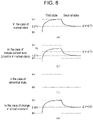
- Figs. 6(a) to 6(d) are diagrams showing an example of measured waveforms that are obtained at a failure diagnosis of leakage detecting device 10 according to the exemplary embodiment.
- the resistance value of first resistance R1 is set to 200 kQ
- the resistance value of second resistance R2 is set to 1000 kQ
- the resistance value of third resistance R3 is set to 1000 kQ.
- the first voltage output unit outputs the first reference voltage (which is 5 V in the present exemplary embodiment) while the second voltage output unit outputs the second reference voltage (which is 0 V in the present exemplary embodiment), and that in the second state, the first voltage output unit outputs the second reference voltage while the second voltage output unit outputs the first reference voltage.
- Fig. 6(a) shows an example of a measured waveform in a case where leakage detecting device 10 is in the normal state.
- first voltage output unit, first resistance R1, second resistance R2, third resistance R3, the second voltage output unit, second operational amplifier OP2, and voltage measurement unit 11b are in the normal state, about 2.27 V is measured in the first state, and about 2.73 V is measured in the second state.
- a theoretical value for the measured voltage in the first state and a theoretical value for the measured voltage in the second state are given by the following (Formula 1) and (Formula 2). 5 ⁇ 1000 / 200 + 1000 + 1000 + 1000 ⁇ 2.27 5 ⁇ 200 + 1000 / 200 + 1000 + 1000 + 1000 ⁇ 2.73
- Diagnosing unit 11d calculates differential voltage ⁇ V between both theoretical values. In this example, differential voltage ⁇ V is calculated as 0.46 V. When differential voltage ⁇ V is within a set range, diagnosing unit 11d determines that leakage detecting device 10 is in the normal state.
- the set range is determined to be a range in which optimum precision is achieved, based on data obtained by experiments or simulations by the designer.
- FIG. 7 is a diagram showing an example of a leak path of power supply system 5 including leakage detecting device 10 according to the exemplary embodiment.
- Fig. 6(b) shows an example of a measured waveform in a case where a minute leak current flows from first operational amplifier OP1 to the chassis ground.
- the circuit itself of leakage detecting device 10 is in the normal state.
- Fig. 6(b) demonstrates that the measured waveform as a whole drops in voltage level by 1 V due to the influence of the leak current. About 1.27 V is measured in the first state, and about 1.72 V is measured in the second state. Differential voltage ⁇ V, i.e., a difference between these measured voltages is 0.46 V.
- Fig. 6(c) shows an example of a measured waveform in a case where leakage detecting device 10 is in the abnormal state.
- Fig. 6(c) demonstrates that a voltage around 0 V is measured in both the first state and the second state. Differential voltage ⁇ V, i.e., a difference between these measured voltages is 0 V. Because differential voltage ⁇ V is out of the given set range (of which the center value is 0.46 V), diagnosing unit 11d determines that leakage detecting device 10 is in the abnormal state.
- Fig. 6(d) shows an example of a measured waveform in a case where the constant of a circuit element used in leakage detecting device 10 has changed.
- the measured waveform shown in Fig. 6(d) is a measured waveform that results when the resistance value of first resistance R1 drops from 200 k ⁇ to 100 k ⁇ because of deterioration of first resistance R1.
- About 2.38 V is measured in the first state, and about 2.62 V is measured in the second state.
- a theoretical value for the measured voltage in the first state and a theoretical value for the measured voltage in the second state are given by the following (Formula 3) and (Formula 4). 5 ⁇ 1000 / 100 + 1000 + 1000 ⁇ 2.38 5 ⁇ 100 + 1000 / 100 + 1000 + 1000 + 1000 ⁇ 2.62
- Differential voltage ⁇ V i.e., a difference between these measured voltages is 0.24 V. Because differential voltage ⁇ V is out of the given set range (of which the center value is 0.46 V), diagnosing unit 11d determines that leakage detecting device 10 is in the abnormal state.
- a failure diagnosis of leakage detecting device 10 can be carried out highly precisely. Specifically, even when a minute leak current flows from first operational amplifier OP1 to the chassis ground, the value of differential voltage ⁇ V is almost the same as that in the case of the normal state, as indicated in Fig. 6(b) . In this case, therefore, a failure diagnosis of leakage detecting device 10 can be carried out under little influence of the minute leakage current. In contrast, in the comparative example as shown in Fig. 3(b) , the influence of the minute leakage current is greater. In the present exemplary embodiment, providing the set range with a large margin is unnecessary, which reduces cases of overlooking a minor problem with a circuit element.
- a change in the constant of a circuit element can be detected. Specifically, deterioration of first resistance R1 functioning as a detection resistance can be detected. In contrast, detecting a change in the constant of the circuit element is difficult in the comparative example, as indicated in Fig. 3(d) .
- Figs. 8(a) to 8(d) show an example of measured waveforms that are obtained at a failure diagnosis of leakage detecting device 10 according to a first modification.
- the configuration of leakage detecting device 10 is the same as the configuration of leakage detecting device 10 shown in Fig. 5 . It is assumed that in the first modification, the resistance value of first resistance R1 is set to 200 kQ, the resistance value of second resistance R2 is set to 1000 kQ, and the resistance value of the third resistance R3 is set to 1000 kQ.
- the first voltage output unit outputs the first reference voltage (which is 5 V in the first modification, too) while the second voltage output unit outputs the first reference voltage
- the first voltage output unit outputs the first reference voltage while the second voltage output unit outputs the second reference voltage (which is 0 V in the first modification, too).
- Fig. 8(a) shows an example of a measured waveform in a case where leakage detecting device 10 is in the normal state.
- first voltage output unit, first resistance R1, second resistance R2, third resistance R3, the second voltage output unit, second operational amplifier OP2, and voltage measurement unit 11b are in the normal state, about 5 V is measured in the first state, and about 2.27 V is measured in the second state. Because 5 V is applied across both ends of first resistance R1, second resistance R2, and third resistance R3 connected in series in the first state, a theoretical vale for the measured voltage in the first state is also 5 V.
- a theoretical value for the measured voltage in the second state is given by the above (Formula 1).
- Diagnosing unit 11d calculates differential voltage ⁇ V between both theoretical values.
- differential voltage ⁇ V is calculated as 2.73 V.
- diagnosing unit 11d determines that leakage detecting device 10 is in the normal state.
- Fig. 8(b) shows an example of a measured waveform in a case where a minute leak current flows from first operational amplifier OP1 to the chassis ground.
- the circuit itself of leakage detecting device 10 is in the normal state.
- Fig. 8(b) demonstrates that the measured waveform as a whole drops in voltage level by 1 V due to the influence of the leak current. About 4 V is measured in the first state, and about 1.27 V is measured in the second state.
- Differential voltage ⁇ V i.e., a difference between both measured voltages is 2.73 V. Because differential voltage ⁇ V falls within the given set range (of which the center value is 2.73 V), diagnosing unit 11d determines that electrical leakage detecting device 10 is in the normal state.
- Fig. 8(c) shows an example of a measured waveform in a case where leakage detecting device 10 is in the abnormal state.
- Fig. 8(c) demonstrates that a voltage around 0 V is measured in both the first state and the second state. Differential voltage ⁇ V, i.e., a difference between these measured voltages is 0 V. Because differential voltage ⁇ V is out of the given set range (of which the center value is 2.73 V), diagnosing unit 11d determines that leakage detecting device 10 is in the abnormal state.
- Fig. 8(d) shows an example of a measured waveform in a case where the constant of a circuit element used in leakage detecting device 10 has changed.
- the measured waveform shown in Fig. 8(d) is a measured waveform that results when the resistance value of the first resistance R1 drops from 200 k ⁇ to 100 k ⁇ because of deterioration of first resistance R1.
- About 5 V is measured in the first state, and about 2.38 V is measured in the second state. Because 5 V is applied across both ends of first resistance R1, second resistance R2, and third resistance R3 connected in series in the first state, a theoretical vale for the measured voltage in the first state is also 5 V, regardless of the resistance value of the first resistance.
- a theoretical value for the measured voltage in the second state is given by the above (Formula 3).
- Differential voltage ⁇ V i.e., a difference between both measured voltages is 2.62 V. Because differential voltage ⁇ V is out of the given set range (of which the center value is 2.73 V), diagnosing unit 11d determines that leakage detecting device 10 is in the abnormal state.
- the first voltage output unit may continuously output the second reference voltage, instead of continuously outputting the first reference voltage.
- Figs. 9(a) to 9(d) are diagrams showing an example of measured waveforms that are obtained at a failure diagnosis of leakage detecting device 10 according to a second modification.
- the configuration of leakage detecting device 10 is the same as the configuration of leakage detecting device 10 shown in Fig. 5 .
- the resistance value of first resistance R1 is set to 200 kQ
- the resistance value of second resistance R2 is set to 1000 kQ
- the resistance value of third resistance R3 is set to 1000 k ⁇ It is also assumed that in the first state, the first voltage output unit outputs the first reference voltage (which is 5 V in the second modification, too) while the second voltage output unit outputs the first reference voltage, and that in the second state, the first voltage output unit outputs the second reference voltage (which is 0 V in the second modification, too) while the second voltage output unit outputs the first reference voltage.
- Fig. 9(a) shows an example of a measured waveform in a case where leakage detecting device 10 is in the normal state.
- first voltage output unit, first resistance R1, second resistance R2, third resistance R3, the second voltage output unit, second operational amplifier OP2, and voltage measurement unit 11b are in the normal state, about 5 V is measured in the first state, and about 2.73 V is measured in the second state. Because 5 V is applied across both ends of first resistance R1, second resistance R2, and third resistance R3 connected in series in the first state, a theoretical vale for the measured voltage in the first state is also 5 V.
- a theoretical value for the measured voltage in the second state is given by the above (Formula 2).
- Diagnosing unit 11d calculates differential voltage ⁇ V between both theoretical values.
- differential voltage ⁇ V is calculated as 2.27 V.
- diagnosing unit 11d determines that leakage detecting device 10 is in the normal state.
- Fig. 9(b) shows an example of a measured waveform in a case where a minute leak current flows from first operational amplifier OP1 to the chassis ground.
- the circuit itself of leakage detecting device 10 is in the normal state.
- Fig. 9(b) demonstrates that the measured waveform as a whole drops in voltage level by 1 V due to the influence of the leak current. About 4 V is measured in the first state, and about 1.73 V is measured in the second state.
- Differential voltage ⁇ V i.e., a difference between both measured voltages is 2.27 V. Because differential voltage ⁇ V falls within the given set range (of which the center value is 2.27 V), diagnosing unit 11d determines that electrical leakage detecting device 10 is in the normal state
- Fig. 9(c) shows an example of a measured waveform in a case where leakage detecting device 10 is in the abnormal state.
- Fig. 9(c) demonstrates that a voltage around 0 V is measured in both the first state and the second state. Differential voltage ⁇ V, i.e., a difference between these measured voltages is 0 V. Because differential voltage ⁇ V is out of the given set range (of which the center value is 2.27 V), diagnosing unit 11d determines that leakage detecting device 10 is in the abnormal state
- Fig. 9(d) shows an example of a measured waveform in a case where the constant of a circuit element used in leakage detecting device 10 has changed.
- the measured waveform shown in Fig. 9(d) is a measured waveform that results when the resistance value of first resistance R1 drops from 200 k ⁇ to 100 k ⁇ because of deterioration of first resistance R1.
- About 5 V is measured in the first state, and about 2.62 V is measured in the second state. Because 5 V is applied across both ends of first resistance R1, second resistance R2, and third resistance R3 connected in series in the first state, a theoretical vale for the measured voltage in the first state is also 5 V, regardless of the resistance value of the first resistance.
- the second voltage output unit may continuously output the second reference voltage, instead of continuously outputting the first reference voltage.
- the above exemplary embodiment has been described as an example in which the power supply voltage of 5 V is used as the first reference voltage and the ground voltage of 0 V is used as the second reference voltage.
- the first reference voltage and the second reference voltage are, however, not limited to 5 V and 0 V, respectively, and arbitrarily chosen two types of voltages may be used as the first reference voltage and the second reference voltage.
- leakage determining unit 11c can specify a peak-to-peak value from the voltage waveform of a voltage at measurement point A and determine the presence or absence of a current leakage in the same manner as in the above exemplary embodiment.
- leakage detecting device 10 incorporated in an electric vehicle is used.
- Leakage detecting device 10 may also be used in applications different from in-vehicle applications.
- the load may be provided as any type of a load.
- the load may be a load used in a railway vehicle.
- the exemplary embodiment may be defined by the following items.
- Leakage detecting device comprising: coupling capacitor (Cc) in a state of being insulated from a ground, coupling capacitor (Cc) having one end connected to a current path of power storage unit (20) connected to load (2); first voltage output unit (11a, OP1) that generates a cyclic voltage that changes cyclically, first voltage output unit (11a, OP1) applying the cyclic voltage to another end of coupling capacitor (Cc) via first resistance (R1); second voltage output unit (11e, OP3) that outputs a fixed voltage; second resistance (R2) and third resistance (R3) that are connected in series between a node and second voltage output unit (11e, OP3), the node being between coupling capacitor (Cc) and first resistance (R1); voltage measurement unit (11b) that measures a voltage at a voltage dividing point between second resistance (R2) and third resistance (R3); leakage determining unit (11c) that in a state of the cyclic voltage being outputted from first voltage output unit (11a,
- Leakage detecting device (10) according to item 1, in which when a difference between a voltage measured in a first state in the period and a voltage measured in a second state in the period is out of a set range, diagnosing unit (11d) determines that leakage detecting device (10) is in an abnormal state, and the second state is different from the first state in at least either an output voltage from first voltage output unit (11a, OP1) or an output voltage from second voltage output unit (11e, OP3).
- Leakage detecting device (10) in which first voltage output unit (11a, OP1) outputs a first reference voltage in the first state and outputs a second reference voltage in the second state, while second voltage output unit (11e, OP3) outputs the second reference voltage in the first state and outputs first reference voltage in the second state.
- Leakage detecting device (10) in which first voltage output unit (11a, OP1) continuously outputs a first reference voltage or a second reference voltage in the first state and the second state, while second voltage output unit (11e, OP3) outputs the first reference voltage in the first state and outputs the second reference voltage in the second state.
- Leakage detecting device (10) in which first voltage output unit (11a, OP1) outputs a first reference voltage in the first state and outputs a second reference voltage in the second state, while second voltage output unit (11e, OP3) continuously outputs the first reference voltage or the second reference voltage in the first state and the second state.
- Leakage detecting device (10) according to any one of item 3 to item 5, in which the first reference voltage is a high-side reference voltage, and the second reference voltage is a low-side reference voltage.
- the first reference voltage and the second reference voltage can be generated easily.
- Vehicular power supply system (5) comprising: power storage unit (20) that is incorporated in a vehicle, power storage unit (20) being kept insulated from a chassis ground of the vehicle, and that supplies power to load (2) in the vehicle; and leakage detecting device (10) described in any one of item 1 to item 6.
- vehicular power supply system (5) including leakage detecting device (10) capable of carrying out a failure diagnosis of itself with high accuracy is provided.
Landscapes
- Engineering & Computer Science (AREA)
- Power Engineering (AREA)
- Physics & Mathematics (AREA)
- General Physics & Mathematics (AREA)
- Life Sciences & Earth Sciences (AREA)
- Sustainable Development (AREA)
- Sustainable Energy (AREA)
- Transportation (AREA)
- Mechanical Engineering (AREA)
- Testing Of Short-Circuits, Discontinuities, Leakage, Or Incorrect Line Connections (AREA)
Abstract
Description
- The present invention relates to a leakage detecting device that detects a current leakage from a load insulated from a ground, and to a vehicular power supply system.
- Hybrid vehicles (HV), plug-in hybrid vehicles (PHV), and electric vehicles (EV) have become widespread in recent years. These electric vehicles are equipped with auxiliary batteries (which are, in general, lead batteries with power output of 12 V) and with drive batteries for high-voltage use (traction batteries), which are separated from the auxiliary batteries. To prevent an electric shock accident, a high-voltage circuit including a drive battery for high voltage use, an inverter, and a running motor is insulated from the body (chassis ground) of a vehicle.
- A Y capacitor is provided between a positive line of the high-voltage circuit, the positive line being on a vehicle side, and the chassis ground and between a negative line of the high-voltage circuit, the negative line being on the vehicle side, and the chassis ground as well. This stabilizes power supply from the high-voltage drive battery to a load on the vehicle side. A leakage detecting device is incorporated in a vehicle to monitor insulation resistance between the high-voltage circuit and the chassis ground and detect a current leakage.
- A leakage detecting device of an AC type applies a pulse voltage to a positive-electrode terminal or a negative-electrode terminal of the drive battery via a resistance and a coupling capacitor, and measures a voltage at a node between the resistance and the coupling capacitor, thereby detecting the presence or absence of a current leakage.
- Meanwhile, a failure of the leakage detecting device of the AC type itself needs to be detected, too, and one of methods of diagnosing a failure of the leakage detecting device of the AC type is a method of applying a pulse voltage with a frequency sufficiently lower than the frequency of the pulse voltage for leak detection, comparing the applied voltage with a measured voltage, and determining that the device is in a normal state when both applied voltage and measured voltage are close to each other (see, for example, PTL 1).
- PTL 1:
WO 2010/058855 A - When a current leakage from the coupling capacitor increases due to deterioration of the coupling capacitor, a leak current increases, the leak current flowing from the leakage detecting device to the chassis ground through the coupling capacitor and the high-voltage electric circuit of the vehicle. According to the above method of diagnosing a failure of the leakage detecting device, an increase in the leak current results in a drop in the applied pulse voltage, which creates a large difference between the applied voltage and the measured voltage. This increases a possibility that the leakage detecting device of a normal state may be determined to be that of an abnormal state. To prevent such an erroneous determination, criteria for determining whether both applied voltage and measured voltage are close to each other needs to be less strict. Less strict criteria, however, increases a possibility that the leakage detecting device of an abnormal state may be determined to be that of a normal state.
- The present disclosure has been made in view of the above circumstance, and it is therefore an object of the present disclosure to provide a technique for highly precisely carrying out a failure diagnosis of a leakage detecting device.
- In order to solve the above problems, a leakage detecting device according to an aspect of the present disclosure includes: a coupling capacitor in a state of being insulated from a ground, the coupling capacitor having one end connected to a current path of a power storage unit connected to a load; a first voltage output unit that generates a cyclic voltage that changes cyclically, the first voltage output unit applying the cyclic voltage to another end of the coupling capacitor via a first resistance; a second voltage output unit that outputs a fixed voltage; a second resistance and a third resistance that are connected in series between a node and the second voltage output unit, the node being between the coupling capacitor and the first resistance; a voltage measurement unit that measures a voltage at a voltage dividing point between the second resistance and the third resistance; a leakage determining unit that in a state of the cyclic voltage being outputted from the first voltage output unit, determines presence or absence of a current leakage between the current path of the power storage unit and the ground, based on a voltage measured by the voltage measurement unit; and a diagnosing unit that in a period of two types of fixed voltages being applied to the voltage dividing point in order, determines whether the leakage detecting device is in a normal state, based on a voltage measured by the voltage measurement unit.
- According to the present disclosure, a diagnosis of a failure of the leakage detecting device can be carried out highly precisely.
-
-
Fig. 1 is a diagram for explaining a configuration of a power supply system including a leakage detecting device according to a comparative example. -
Fig. 2 is a diagram showing an example of an applied pulse waveform and a measured voltage waveform. -
Fig. 3 includingFigs. 3(a) to 3(d) is a diagram showing an example of measured waveforms that are obtained at a failure diagnosis of the leakage detecting device according to the comparative example. -
Fig. 4 is a diagram showing an example of a leak path of the power supply system including the leakage detecting device according to the comparative example. -
Fig. 5 is a diagram for explaining a configuration of a power supply system including a leakage detecting device according to an exemplary embodiment. -
Fig. 6 includingFigs. 6(a) to 6(d) is a diagram showing an example of measured waveforms that are obtained at a failure diagnosis of the leakage detecting device according to the exemplary embodiment. -
Fig. 7 is a diagram showing an example of a leak path of a power supply system including the leakage detecting device according to the exemplary embodiment. -
Fig. 8 includingFigs. 8(a) to 8(d) is a diagram showing an example of measured waveforms that are obtained at a failure diagnosis of a leakage detecting device according to a first modification. -
Fig. 9 includingFigs. 9(a) to 9(d) is a diagram showing an example of measured waveforms that are obtained at a failure diagnosis of a leakage detecting device according to a second modification. -
Fig. 1 is a diagram for explaining a configuration ofpower supply system 5 includingleakage detecting device 10 according to a comparative example.Power supply system 5 is incorporated in an electric vehicle. In the electric vehicle,power supply system 5 is provided in separation from an auxiliary battery (which is usually a lead battery with power output of 12 V).Power supply system 5 includespower storage unit 20 for high voltage use andleakage detecting device 10.Power storage unit 20 includes a plurality of cells E1 to En connected in series. Lithium ion battery cells, nickel metal hydride battery cells, lead battery cells, electric double-layer capacitor cells, lithium ion capacitor cells, or the like can be used as cells E1 to En. Hereinafter, in this specification, it is assumed that lithium ion battery cells (with a nominal voltage ranging from 3.6 V to 3.7 V) are used as cells E1 to En. - The electric vehicle includes
inverter 2 andmotor 3 as loads for high voltage use. The positive electrode ofpower storage unit 20 is connected to one end ofinverter 2 through positive line Lp, and the negative electrode ofpower storage unit 20 is connected to the other end ofinverter 2 through negative line Lm. Positive line Lp is provided with positive-side main relay MRp, and negative line Lm is provided with negative-side main relay MRm. Positive-side main relay MRp and negative-side main relay MRm function as contactors that control electrical connection/disconnection betweenpower storage unit 20 and the loads for high-voltage use in the electric vehicle. In place of these relays, semiconductor switches with high withstand voltage and insulation performance may be used. -
Inverter 2 is a bidirectional inverter connected betweenpower storage unit 20 andmotor 3. In power running mode, inverter 2 converts DC power, which is supplied frompower storage unit 20, into AC power and supplies the AC power tomotor 3. In power regeneration mode, inverter 2 converts AC power, which is supplied frommotor 3, into DC power and supplies the DC power topower storage unit 20. Asmotor 3, for example, a three-phase AC motor is used. In power running mode,motor 3 rotates in accordance with AC power supplied frominverter 2. In power regeneration mode,motor 3 converts rotational energy created by deceleration into AC power and supplied the AC power to inverter 2. -
Power storage unit 20 is incorporated in the electric vehicle such thatpower storage unit 20 is kept insulated from a chassis ground of the electric vehicle. The auxiliary battery is incorporated in the electric vehicle such that the negative electrode of the auxiliary battery is electrically connected to the chassis ground. A part of positive line Lp that is closer to inverter 2 than positive-side main relay MRp is connected to the chassis ground via positive-side Y capacitor Cp. In addition, a part of negative line Lm that is closer to inverter 2 than negative-side main relay MRm is connected to the chassis ground via negative-side Y capacitor Cm. Positive-side Y capacitor Cp and negative-side Y capacitor Cm provide DC-based insulation between positive line Lp and the chassis ground and DC-based insulation between negative line Lm and the chassis ground, respectively, and exert an effect of stabilizing respective voltages of positive line Lp and negative line Lm. - When
power storage unit 20 is insulated from the chassis ground in an ideal manner, an intermediate potential ofpower storage unit 20 is kept close to a potential of the chassis ground. For example, when a voltage across both ends ofpower storage unit 20 is 250 V, a positive electrode potential ofpower storage unit 20 is kept close to +125 V as a negative electrode potential of the same is kept close to -125 V. Whenpower storage unit 20 for high voltage use and the chassis ground are in a state of being electrically connected to each other, a person's touching an exposed conductive part of the electric vehicle is so dangerous that it may give an electric shock to the person. For this reason, it is necessary that the electric vehicle includingpower storage unit 20 for high voltage use be equipped withleakage detecting device 10 to monitor a state of insulation between a current path ofpower storage unit 20, which is connected to vehicle loads for high voltage use, and the chassis ground. InFig. 1 , a state of insulation between positive line Lp and the chassis ground is expressed as positive-side leakage resistance Rlp, and a state of insulation between negative line Lm and the chassis ground is expressed as negative-side leakage resistance Rlm. - In the comparative example,
leakage detecting device 10 includes coupling capacitor Cc, first resistance R1, first operational amplifier OP1, second resistance R2, smoothing capacitor C1, second operational amplifier OP2, andcontroller 11.Controller 11 includesoscillator 11a,voltage measurement unit 11b,leakage determining unit 11c, anddiagnosing unit 11d.Controller 11 may be composed of, for example, a microcomputer and a nonvolatile memory (e.g., an electrically erasable programmable read-only memory (EEPROM), a flash memory, or the like). - Coupling capacitor Cc has one end connected to the current path of
power storage unit 20. In the example shown inFig. 1 , the one end of coupling capacitor Cc is connected to the negative electrode ofpower storage unit 20. The one end of coupling capacitor Cc may be connected to the positive electrode ofpower storage unit 20 or may be connected to a node of one of the plurality of cells E1 to En inpower storage unit 20. The other end of coupling capacitor Cc is connected to an output end of a voltage output unit via first resistance R1. A node between the other end of coupling capacitor Cc and first resistance R1 serves as measurement point A. A different impedance element may be used in place of first resistance R1. - In
Fig. 1 , as coupling capacitor Cc, an aluminum electrolytic capacitor is used, which can be increased in capacity at relatively low cost. The aluminum electrolytic capacitor has polarity. InFig. 1 , the positive electrode of the aluminum electrolytic capacitor is connected to measurement point A, while the negative electrode of the aluminum electrolytic capacitor is connected to the negative electrode ofpower storage unit 20. Coupling capacitor Cc may be composed of a plurality of aluminum electrolytic capacitors connected in series. In this case, even if one capacitor short-circuits, the rest of the capacitors maintain DC-based insulation. - The above voltage output unit generates a cyclic voltage that changes cyclically, and applies the generated cyclic voltage to the other end of coupling capacitor Cc via first resistance R1. Hereinafter, in the present specification, it is assumed that a rectangular wave voltage is used as the cyclic voltage.
- The voltage output unit includes
oscillator 11a and first operational amplifier OP1.Oscillator 11a includes a multi-vibrator or a local oscillator, and generates a rectangular wave with a preset frequency. The rectangular wave voltage generated byoscillator 11a is input to a non-inverting input terminal of first operational amplifier OP1. An output terminal of first operational amplifier OP1 is connected to first resistance R1. An inverting input terminal of first operational amplifier OP1 is connected to an output terminal of the same. A positive power source terminal of first operational amplifier OP1 is connected to a first fixed potential node (power source potential Vcc), and a negative power source terminal of first operational amplifier OP1 is connected to a second fixed potential node (ground potential GND). Hereinafter, in the present specification, it is assumed that power source potential Vcc is 5 V and ground potential GND is 0 V. - First operational amplifier OP1 functions as a voltage follower that performs only impedance conversion with an amplification factor of 1. In place of first operational amplifier OP1, an AND gate having one input terminal connected to the first fixed potential node or an OR gate having one input terminal connected to the second fixed potential node may be used. First operational amplifier OP1 may be substituted by any element that functions as a buffer that separates the impedance of
controller 11 from the impedance of measurement point A. - Measurement point A is connected to a non-inverting input terminal of second operational amplifier OP2 via second resistance R2. An inverting input terminal of second operational amplifier OP2 is connected to an output terminal of the same. Second operational amplifier OP2 also functions as a voltage follower that performs only impedance conversion with an amplification factor of 1. Smoothing capacitor C1 is connected between the non-inverting input terminal of second operational amplifier OP2 and the second fixed potential node (ground potential GND). Smoothing capacitor C1 removes noise from voltage input to the non-inverting input terminal of second operational amplifier OP2.
- Second operational amplifier OP2 outputs a voltage at measurement point A to
voltage measurement unit 11b.Voltage measurement unit 11b measures the voltage at measurement point A.Voltage measurement unit 11b includes an A/D converter, and the A/D converter samples an analog voltage at measurement point A at points of time synchronizing with points of time of rising edges and falling edges of a rectangular wave voltage generated byoscillator 11a, and converts the sampled analog voltage into a digital value. The voltage sampled at points of time of rising edges of the rectangular wave voltage corresponds to lower peak values of a voltage waveform resulting from the sampling, and the voltage sampled at points of time of falling edges of the rectangular wave voltage corresponds to upper peak values of the voltage waveform resulting from the sampling. It should be noted that, in consideration of distortion of the rectangular wave voltage, timing of sampling for the lower peak values and timing of sampling for the upper peak values may be adjusted.Voltage measurement unit 11b outputs the voltage at measurement point A toleakage determining unit 11c and to diagnosingunit 11d. -
Leakage determining unit 11c determines the presence or absence of a current leakage between the current path ofpower storage unit 20 and the chassis ground, based on the voltage at measurement point A measured byvoltage measurement unit 11b. When a peak-to-peak value indicated by a difference between an upper peak value and a lower peak value is smaller than a set value,leakage determining unit 11c determines that a current leakage has occurred between the current path ofpower storage unit 20 and the chassis ground. The set value is determined, based on a peak-to-peak value of a voltage waveform measured at the occurrence of a current leakage, the peak-to-peak value being derived in advance through an experiment or simulation by a designer. When a current leakage has occurred between the current path ofpower storage unit 20 and the chassis ground, an alternating current flows from first operational amplifier OP1 to coupling capacitor Cc via first resistance R1 working as a detection resistance. A current flowing through first resistance R1 causes a voltage drop, which reduces the amplitude of the voltage at measurement point A. -
Fig. 2 is a diagram showing an example of an applied pulse waveform and a measured voltage waveform. A pulse waveform applied from the voltage output unit to measurement point A has a high-side potential set to 5 V and a low-side potential set to 0 V.Leakage determining unit 11c identifies upper peak value Vp1 and lower peak value Vp2 of a voltage waveform measured in a period during which the pulse voltage is kept applied to measurement point A, and determines the presence or absence of a current leakage, based on a peak-to-peak value defined as a difference between upper peak value Vp1 and lower peak value Vp2. - Now
Fig. 1 will be referred to again. Diagnosingunit 11d determines whetherleakage detecting device 10 is in a normal state, based on a voltage measured byvoltage measurement unit 11b. In other words, diagnosingunit 11d determines whetherleakage detecting device 10 itself has a failure. When a failure diagnosis ofleakage detecting device 10 is carried out, a pulse voltage with a frequency sufficiently lower than the frequency of the voltage for leakage detection is applied to measurement point A. For example, a 10 Hz pulse voltage may be applied at leak detection, and a 1 Hz pulse voltage may be applied at failure diagnosis ofleakage detecting device 10. -
Figs. 3(a) to 3(d) are diagrams showing an example of measured waveforms that are obtained at a failure diagnosis ofleakage detecting device 10 according to the comparative example.Fig. 3(a) shows an example of a measured waveform in a case ofleakage detecting device 10 being in the normal state. When a path leading fromoscillator 11a through first operational amplifier OP1, first resistance R1, second resistance R2, and second operational amplifier OP2 to thevoltage measurement unit 11b is in a normal state, a pulse voltage outputted fromoscillator 11a is measured in its original form byvoltage measurement unit 11b. It should be noted that a measured waveform is distorted due to the influence of smoothing capacitor C1. When a voltage measured during the high-level period of the applied pulse voltage is close to a first reference voltage (which is 5 V in the comparative example) and a voltage measured during the low-level period of the same is close to a second reference voltage (which is 0 V in the comparative example), diagnosingunit 11d determines thatleakage detecting device 10 is in the normal state. - Meanwhile, when coupling capacitor Cc deteriorates, a leak current increases. In a case of using an aluminum electrolytic capacitor as coupling capacitor Cc, leaving coupling capacitor Cc in a non-load state for a long period is likely to result in an increase in the leak current.
-
Fig. 4 is a diagram showing an example of a leak path ofpower supply system 5 includingleakage detecting device 10 according to the comparative example. Between the current path ofpower storage unit 20 and the chassis ground, even under a normal condition, a minute leak current flows as leakage resistance ranges from several tens of MΩ to 100 MΩ. Even when positive-side main relay MRp and negative-side main relay MRm are off (opened), a minute leak current flows between the current path ofpower storage unit 20 and the chassis ground (see leakage resistance Rlb). When the insulation resistance of coupling capacitor Cc drops, a minute leak current flows through a path leading from first operational amplifier OP1 through first resistance R1, coupling capacitor Cc, andpower storage unit 20 to leakage resistance Rlb. For example, when the resistance value of first resistance R1 is set to 200 kQ, if the insulation resistance of coupling capacitor Cc drops to about 20 MΩ, the leak current exerts its influence on a pulse voltage generated by a 5 V power supply, causing a measured pulse voltage waveform a voltage drop of about 1 V. -
Fig. 3(b) shows an example of a measured waveform in a case where a minute leak current flows from first operational amplifier OP1 to the chassis ground. The circuit itself ofleakage detecting device 10 is in the normal state.Fig. 3(b) demonstrates that the measured waveform as a whole drops in voltage level due to the influence of the leak current. In the examples ofFigs. 3(a) to 3(d) , a measurement circuit incapable of detecting a voltage lower than 0 V is used. For this reason, the measured voltage is clamped to 0 V in most of the low-side period of the applied pulse voltage. -
Fig. 3(c) shows an example of a measured waveform in a case whereleakage detecting device 10 is in an abnormal state.Fig. 3(c) demonstrates that a voltage around 0 V is measured in both the high-level period and the low-level period of the applied pulse voltage. When a voltage measured during the high-level period of the applied pulse voltage is different from the first reference voltage (which is 5 V in the comparative example) by a specified value or more, diagnosingunit 11d determines thatleakage detecting device 10 is in the abnormal state. For example, when any part of the path leading fromoscillator 11a through first operational amplifier OP1, first resistance R1, second resistance R2, and second operational amplifier OP2 tovoltage measurement unit 11b is disconnected, a voltage around 0 V is measured also in the high-level period of the applied pulse voltage. In other cases where a short failure or an open failure occurs at any of circuit elements, the voltage measured in the high-level period is widely different from the first reference voltage. -
Fig. 3(d) shows an example of a measured waveform in a case where the constant of a circuit element used inleakage detecting device 10 changes. In the comparative example, even when the constant of a circuit element changes, the measured waveform of the applied pulse voltage hardly changes from the same in the case ofleakage detecting device 10 being in the normal state. For example, when the resistance value of first resistance R1 drops from 200 kΩ to 100 kΩ because of deterioration of first resistance R1, the measured waveform of the pulse voltage hardly changes. - As indicated in
Fig. 3(b) , a method of diagnosis ofleakage detecting device 10 according to the comparative example is widely affected by the minute leakage current flowing from first operational amplifier OP1 to the chassis ground. In the example shown inFig. 3(b) , since the circuit itself ofleakage detecting device 10 is in the normal state, diagnosingunit 11d is expected to give a determination thatleakage detecting device 10 is in the normal state. Actually, however, a measurement of the applied pulse voltage in the high-side period turns out to be around 4 V, which is widely different from 5 V that is the original theoretical value. To allow determining this state to be a normal state, a margin of about 1 V needs to be added to the specified value for the determination, which means that the criteria need to be widely relaxed. Taking such an approach leads to a case where a small failure of a circuit element is overlooked. In addition, as indicated inFig. 3(d) , by the method of diagnosis ofleakage detecting device 10 according to the comparative example, detecting a change in the constant of a circuit element is difficult. Specifically, detecting deterioration of first resistance R1 is difficult. -
Fig. 5 is a diagram for explaining a configuration ofpower supply system 5 includingleakage detecting device 10 according to an exemplary embodiment. Hereinafter, differences in configuration withpower supply system 5 according to the comparative example shown inFig. 1 will be described. In the exemplary embodiment,leakage detecting device 10 additionally includes third resistance R3 and third operational amplifier OP3.Controller 11 further includes constantvoltage output unit 11e. Constantvoltage output unit 11e can output two types of fixed voltages: the first reference voltage (which is 5 V in the present exemplary embodiment) and the second reference voltage (which is 0 V in the present exemplary embodiment). - In the present exemplary embodiment,
oscillator 11a and first operational amplifier OP1 make up a first voltage output unit, and constantvoltage output unit 11e and third operational amplifier OP3 make up a second voltage output unit. In the present exemplary embodiment, the first voltage output unit is also configured to be capable of outputting the two types of fixed voltages, i.e., the first reference voltage and the second reference voltage. - Second resistance R2 and third resistance R3 are connected in series between node A and the second voltage output unit, node A being between coupling capacitor Cc and first resistance R1. More specifically, a constant voltage outputted from constant
voltage output unit 11e is inputted to a non-inverting input terminal of third operational amplifier OP3. An output terminal of third operational amplifier OP3 is connected to third resistance R3. An inverting input terminal of third operational amplifier OP3 is connected to the output terminal of the same. Third operational amplifier OP3 also functions as a voltage follower that performs only impedance conversion with an amplification factor of 1. - In the present exemplary embodiment, a voltage at a voltage dividing point between second resistance R2 and third resistance R3 is input to the non-inverting input terminal of second operational amplifier OP2. In other words, by measuring the voltage at the voltage dividing point between second resistance R2 and third resistance R3,
voltage measurement unit 11b measures a voltage at measurement point A in its compressed form. Based on the amplitude value of the voltage measured byvoltage measurement unit 11b,leakage determining unit 11c calculates a leakage resistance value, referring to a leakage resistance conversion table, thereby determining the presence or absence of a current leakage between the current path ofpower storage unit 20 and the chassis ground. In the present exemplary embodiment, the voltage at measurement point A is measured in the form of a divided voltage. This reduces periods in which the voltage at measurement point A is out of a measurement range (which is a range of 0 V to 5 V, inclusive in the present exemplary embodiment). In other words, periods in which leakage determination cannot be made are reduced. - In a period in which the two types of fixed voltages are outputted in order from the first voltage output unit, diagnosing
unit 11d determines whetherleakage detecting device 10 is in the normal state, based on the voltage measured byvoltage measurement unit 11b. Specifically, diagnosingunit 11d calculates a difference between a voltage measured in a first state in the period and a voltage measured in a second state in the period, and determines thatleakage detecting device 10 is in the normal state when the difference is within a set range. The first state and the second state each continue for several seconds (e.g., 4 seconds). -
Figs. 6(a) to 6(d) are diagrams showing an example of measured waveforms that are obtained at a failure diagnosis ofleakage detecting device 10 according to the exemplary embodiment. In the following example, it is assumed that the resistance value of first resistance R1 is set to 200 kQ, the resistance value of second resistance R2 is set to 1000 kQ, and the resistance value of third resistance R3 is set to 1000 kQ. It is also assumed that in the first state, the first voltage output unit outputs the first reference voltage (which is 5 V in the present exemplary embodiment) while the second voltage output unit outputs the second reference voltage (which is 0 V in the present exemplary embodiment), and that in the second state, the first voltage output unit outputs the second reference voltage while the second voltage output unit outputs the first reference voltage. -
Fig. 6(a) shows an example of a measured waveform in a case whereleakage detecting device 10 is in the normal state. When the first voltage output unit, first resistance R1, second resistance R2, third resistance R3, the second voltage output unit, second operational amplifier OP2, andvoltage measurement unit 11b are in the normal state, about 2.27 V is measured in the first state, and about 2.73 V is measured in the second state. A theoretical value for the measured voltage in the first state and a theoretical value for the measured voltage in the second state are given by the following (Formula 1) and (Formula 2).


- Diagnosing
unit 11d calculates differential voltage ΔV between both theoretical values. In this example, differential voltage ΔV is calculated as 0.46 V. When differential voltage ΔV is within a set range, diagnosingunit 11d determines thatleakage detecting device 10 is in the normal state. The set range is determined to be a range in which optimum precision is achieved, based on data obtained by experiments or simulations by the designer. - In the present exemplary embodiment, in the same manner as in the comparative example, deterioration of coupling capacitor Cc leads to an increase in a leak current.
Fig. 7 is a diagram showing an example of a leak path ofpower supply system 5 includingleakage detecting device 10 according to the exemplary embodiment. -
Fig. 6(b) shows an example of a measured waveform in a case where a minute leak current flows from first operational amplifier OP1 to the chassis ground. The circuit itself ofleakage detecting device 10 is in the normal state.Fig. 6(b) demonstrates that the measured waveform as a whole drops in voltage level by 1 V due to the influence of the leak current. About 1.27 V is measured in the first state, and about 1.72 V is measured in the second state. Differential voltage ΔV, i.e., a difference between these measured voltages is 0.46 V. -
Fig. 6(c) shows an example of a measured waveform in a case whereleakage detecting device 10 is in the abnormal state.Fig. 6(c) demonstrates that a voltage around 0 V is measured in both the first state and the second state. Differential voltage ΔV, i.e., a difference between these measured voltages is 0 V. Because differential voltage ΔV is out of the given set range (of which the center value is 0.46 V), diagnosingunit 11d determines thatleakage detecting device 10 is in the abnormal state. -
Fig. 6(d) shows an example of a measured waveform in a case where the constant of a circuit element used inleakage detecting device 10 has changed. The measured waveform shown inFig. 6(d) is a measured waveform that results when the resistance value of first resistance R1 drops from 200 kΩ to 100 kΩ because of deterioration of first resistance R1. About 2.38 V is measured in the first state, and about 2.62 V is measured in the second state. When the resistance value of first resistance R1 is 100kΩ, a theoretical value for the measured voltage in the first state and a theoretical value for the measured voltage in the second state are given by the following (Formula 3) and (Formula 4).


- Differential voltage ΔV, i.e., a difference between these measured voltages is 0.24 V. Because differential voltage ΔV is out of the given set range (of which the center value is 0.46 V), diagnosing
unit 11d determines thatleakage detecting device 10 is in the abnormal state. - As described above, according to the present exemplary embodiment, by determining whether differential voltage ΔV between the first state and the second state falls within the set range in the period in which the two types of fixed voltages are applied to the voltage dividing point in order, a failure diagnosis of
leakage detecting device 10 can be carried out highly precisely. Specifically, even when a minute leak current flows from first operational amplifier OP1 to the chassis ground, the value of differential voltage ΔV is almost the same as that in the case of the normal state, as indicated inFig. 6(b) . In this case, therefore, a failure diagnosis ofleakage detecting device 10 can be carried out under little influence of the minute leakage current. In contrast, in the comparative example as shown inFig. 3(b) , the influence of the minute leakage current is greater. In the present exemplary embodiment, providing the set range with a large margin is unnecessary, which reduces cases of overlooking a minor problem with a circuit element. - In addition, as indicated in
Fig. 6(d) , according to the present exemplary embodiment, a change in the constant of a circuit element can be detected. Specifically, deterioration of first resistance R1 functioning as a detection resistance can be detected. In contrast, detecting a change in the constant of the circuit element is difficult in the comparative example, as indicated inFig. 3(d) . -
Figs. 8(a) to 8(d) show an example of measured waveforms that are obtained at a failure diagnosis ofleakage detecting device 10 according to a first modification. In the first modification, the configuration ofleakage detecting device 10 is the same as the configuration ofleakage detecting device 10 shown inFig. 5 . It is assumed that in the first modification, the resistance value of first resistance R1 is set to 200 kQ, the resistance value of second resistance R2 is set to 1000 kQ, and the resistance value of the third resistance R3 is set to 1000 kQ. It is also assumed that in the first state, the first voltage output unit outputs the first reference voltage (which is 5 V in the first modification, too) while the second voltage output unit outputs the first reference voltage, and that in the second state, the first voltage output unit outputs the first reference voltage while the second voltage output unit outputs the second reference voltage (which is 0 V in the first modification, too). -
Fig. 8(a) shows an example of a measured waveform in a case whereleakage detecting device 10 is in the normal state. When the first voltage output unit, first resistance R1, second resistance R2, third resistance R3, the second voltage output unit, second operational amplifier OP2, andvoltage measurement unit 11b are in the normal state, about 5 V is measured in the first state, and about 2.27 V is measured in the second state. Because 5 V is applied across both ends of first resistance R1, second resistance R2, and third resistance R3 connected in series in the first state, a theoretical vale for the measured voltage in the first state is also 5 V. A theoretical value for the measured voltage in the second state is given by the above (Formula 1). - Diagnosing
unit 11d calculates differential voltage ΔV between both theoretical values. In this example, differential voltage ΔV is calculated as 2.73 V. When differential voltage ΔV is within a set range, diagnosingunit 11d determines thatleakage detecting device 10 is in the normal state. -
Fig. 8(b) shows an example of a measured waveform in a case where a minute leak current flows from first operational amplifier OP1 to the chassis ground. The circuit itself ofleakage detecting device 10 is in the normal state.Fig. 8(b) demonstrates that the measured waveform as a whole drops in voltage level by 1 V due to the influence of the leak current. About 4 V is measured in the first state, and about 1.27 V is measured in the second state. Differential voltage ΔV, i.e., a difference between both measured voltages is 2.73 V. Because differential voltage ΔV falls within the given set range (of which the center value is 2.73 V), diagnosingunit 11d determines that electricalleakage detecting device 10 is in the normal state. -
Fig. 8(c) shows an example of a measured waveform in a case whereleakage detecting device 10 is in the abnormal state.Fig. 8(c) demonstrates that a voltage around 0 V is measured in both the first state and the second state. Differential voltage ΔV, i.e., a difference between these measured voltages is 0 V. Because differential voltage ΔV is out of the given set range (of which the center value is 2.73 V), diagnosingunit 11d determines thatleakage detecting device 10 is in the abnormal state. -
Fig. 8(d) shows an example of a measured waveform in a case where the constant of a circuit element used inleakage detecting device 10 has changed. The measured waveform shown inFig. 8(d) is a measured waveform that results when the resistance value of the first resistance R1 drops from 200 kΩ to 100 kΩ because of deterioration of first resistance R1. About 5 V is measured in the first state, and about 2.38 V is measured in the second state. Because 5 V is applied across both ends of first resistance R1, second resistance R2, and third resistance R3 connected in series in the first state, a theoretical vale for the measured voltage in the first state is also 5 V, regardless of the resistance value of the first resistance. A theoretical value for the measured voltage in the second state is given by the above (Formula 3). Differential voltage ΔV, i.e., a difference between both measured voltages is 2.62 V. Because differential voltage ΔV is out of the given set range (of which the center value is 2.73 V), diagnosingunit 11d determines thatleakage detecting device 10 is in the abnormal state. - As described above, according to the first modification, even if the first voltage output unit continuously outputs the same voltage in the first state and the second state, the same effect as that of the above exemplary embodiment is achieved by switching the output voltage from the second voltage output unit. The first voltage output unit may continuously output the second reference voltage, instead of continuously outputting the first reference voltage.
-
Figs. 9(a) to 9(d) are diagrams showing an example of measured waveforms that are obtained at a failure diagnosis ofleakage detecting device 10 according to a second modification. In the first modification, the configuration ofleakage detecting device 10 is the same as the configuration ofleakage detecting device 10 shown inFig. 5 . It is assumed that in the second modification, the resistance value of first resistance R1 is set to 200 kQ, the resistance value of second resistance R2 is set to 1000 kQ, and the resistance value of third resistance R3 is set to 1000 kΩ It is also assumed that in the first state, the first voltage output unit outputs the first reference voltage (which is 5 V in the second modification, too) while the second voltage output unit outputs the first reference voltage, and that in the second state, the first voltage output unit outputs the second reference voltage (which is 0 V in the second modification, too) while the second voltage output unit outputs the first reference voltage. -
Fig. 9(a) shows an example of a measured waveform in a case whereleakage detecting device 10 is in the normal state. When the first voltage output unit, first resistance R1, second resistance R2, third resistance R3, the second voltage output unit, second operational amplifier OP2, andvoltage measurement unit 11b are in the normal state, about 5 V is measured in the first state, and about 2.73 V is measured in the second state. Because 5 V is applied across both ends of first resistance R1, second resistance R2, and third resistance R3 connected in series in the first state, a theoretical vale for the measured voltage in the first state is also 5 V. A theoretical value for the measured voltage in the second state is given by the above (Formula 2). - Diagnosing
unit 11d calculates differential voltage ΔV between both theoretical values. In this example, differential voltage ΔV is calculated as 2.27 V. When differential voltage ΔV is within a set range, diagnosingunit 11d determines thatleakage detecting device 10 is in the normal state. -
Fig. 9(b) shows an example of a measured waveform in a case where a minute leak current flows from first operational amplifier OP1 to the chassis ground. The circuit itself ofleakage detecting device 10 is in the normal state.Fig. 9(b) demonstrates that the measured waveform as a whole drops in voltage level by 1 V due to the influence of the leak current. About 4 V is measured in the first state, and about 1.73 V is measured in the second state. Differential voltage ΔV, i.e., a difference between both measured voltages is 2.27 V. Because differential voltage ΔV falls within the given set range (of which the center value is 2.27 V), diagnosingunit 11d determines that electricalleakage detecting device 10 is in the normal state -
Fig. 9(c) shows an example of a measured waveform in a case whereleakage detecting device 10 is in the abnormal state.Fig. 9(c) demonstrates that a voltage around 0 V is measured in both the first state and the second state. Differential voltage ΔV, i.e., a difference between these measured voltages is 0 V. Because differential voltage ΔV is out of the given set range (of which the center value is 2.27 V), diagnosingunit 11d determines thatleakage detecting device 10 is in the abnormal state -
Fig. 9(d) shows an example of a measured waveform in a case where the constant of a circuit element used inleakage detecting device 10 has changed. The measured waveform shown inFig. 9(d) is a measured waveform that results when the resistance value of first resistance R1 drops from 200 kΩ to 100 kΩ because of deterioration of first resistance R1. About 5 V is measured in the first state, and about 2.62 V is measured in the second state. Because 5 V is applied across both ends of first resistance R1, second resistance R2, and third resistance R3 connected in series in the first state, a theoretical vale for the measured voltage in the first state is also 5 V, regardless of the resistance value of the first resistance. A theoretical value for the measured voltage in the second state is given by the above (Formula 4). Differential voltage ΔV, i.e., a difference between both measured voltages is 2.38 V. Because differential voltage ΔV is out of the given set range (of which the center value is 2.27 V), diagnosingunit 11d determines thatleakage detecting device 10 is in the abnormal state - As described above, according to the second modification, even if the second voltage output unit continuously outputs the same voltage in the first state and the second state, the same effect as that of the above exemplary embodiment is achieved by switching the output voltage from the first voltage output unit. In addition, according to the second modification, the theoretical value for the measured voltage in the second state is higher than that in the first modification. As a result, the measured waveform as a hole becomes more resistant to a drop in voltage level. The second voltage output unit may continuously output the second reference voltage, instead of continuously outputting the first reference voltage.
- The present disclosure has been described above, based on the exemplary embodiment. The exemplary embodiment is merely an example of the exemplary embodiment, and it will be understood by those who are skilled in art that various modifications can be made by changing combinations of constituent elements and processes and that such modifications are also within the scope of the present disclosure.
- The above exemplary embodiment has been described as an example in which the power supply voltage of 5 V is used as the first reference voltage and the ground voltage of 0 V is used as the second reference voltage. The first reference voltage and the second reference voltage are, however, not limited to 5 V and 0 V, respectively, and arbitrarily chosen two types of voltages may be used as the first reference voltage and the second reference voltage.
- The above exemplary embodiment has been described as an example in which the rectangular wave voltage is applied from the first voltage output unit to coupling capacitor Cc via first resistance R1. In a different example, however, a sinusoidal voltage may be applied to coupling capacitor Cc. In this example,
leakage determining unit 11c can specify a peak-to-peak value from the voltage waveform of a voltage at measurement point A and determine the presence or absence of a current leakage in the same manner as in the above exemplary embodiment. - The above exemplary embodiment has been described as an example in which
leakage detecting device 10 incorporated in an electric vehicle is used.Leakage detecting device 10 according to the exemplary embodiment, however, may also be used in applications different from in-vehicle applications. In a configuration in whichpower storage unit 20 and a load supplied with power frompower storage unit 20 are insulated from the ground, the load may be provided as any type of a load. For example, the load may be a load used in a railway vehicle. - The exemplary embodiment may be defined by the following items.
- Leakage detecting device (10) comprising: coupling capacitor (Cc) in a state of being insulated from a ground, coupling capacitor (Cc) having one end connected to a current path of power storage unit (20) connected to load (2); first voltage output unit (11a, OP1) that generates a cyclic voltage that changes cyclically, first voltage output unit (11a, OP1) applying the cyclic voltage to another end of coupling capacitor (Cc) via first resistance (R1); second voltage output unit (11e, OP3) that outputs a fixed voltage; second resistance (R2) and third resistance (R3) that are connected in series between a node and second voltage output unit (11e, OP3), the node being between coupling capacitor (Cc) and first resistance (R1); voltage measurement unit (11b) that measures a voltage at a voltage dividing point between second resistance (R2) and third resistance (R3); leakage determining unit (11c) that in a state of the cyclic voltage being outputted from first voltage output unit (11a, OP1), determines presence or absence of a leakage from a line between the current path of power storage unit (20) and the ground, based on a voltage measured by voltage measurement unit (11b); and diagnosing unit (11d) that in a period of two types of fixed voltages being applied to the voltage dividing point in order, determines whether leakage detecting device (10) is in a normal state, based on a voltage measured by voltage measurement unit (11b).
- According to this configuration, a failure diagnosis of leakage detecting device (10) can be carried out highly precisely.
- Leakage detecting device (10) according to
item 1, in which when a difference between a voltage measured in a first state in the period and a voltage measured in a second state in the period is out of a set range, diagnosing unit (11d) determines that leakage detecting device (10) is in an abnormal state, and the second state is different from the first state in at least either an output voltage from first voltage output unit (11a, OP1) or an output voltage from second voltage output unit (11e, OP3). - According to this configuration, a failure diagnosis of leakage detecting device (10) can be carried out highly precisely.
- Leakage detecting device (10) according to
item 2, in which first voltage output unit (11a, OP1) outputs a first reference voltage in the first state and outputs a second reference voltage in the second state, while second voltage output unit (11e, OP3) outputs the second reference voltage in the first state and outputs first reference voltage in the second state. - According to this configuration, a preferable differential voltage for determination can be measured.
- Leakage detecting device (10) according to
item 2, in which first voltage output unit (11a, OP1) continuously outputs a first reference voltage or a second reference voltage in the first state and the second state, while second voltage output unit (11e, OP3) outputs the first reference voltage in the first state and outputs the second reference voltage in the second state. - According to this configuration, a preferable differential voltage for determination can be measured.
- Leakage detecting device (10) according to
item 2, in which first voltage output unit (11a, OP1) outputs a first reference voltage in the first state and outputs a second reference voltage in the second state, while second voltage output unit (11e, OP3) continuously outputs the first reference voltage or the second reference voltage in the first state and the second state. - According to this configuration, a preferable differential voltage for determination can be measured.
- Leakage detecting device (10) according to any one of
item 3 toitem 5, in which the first reference voltage is a high-side reference voltage, and the second reference voltage is a low-side reference voltage. - According to this configuration, the first reference voltage and the second reference voltage can be generated easily.
- Vehicular power supply system (5) comprising: power storage unit (20) that is incorporated in a vehicle, power storage unit (20) being kept insulated from a chassis ground of the vehicle, and that supplies power to load (2) in the vehicle; and leakage detecting device (10) described in any one of
item 1 to item 6. - According to this configuration, vehicular power supply system (5) including leakage detecting device (10) capable of carrying out a failure diagnosis of itself with high accuracy is provided.
-
- 2: inverter
- 3: motor
- Lp: positive line
- Lm: negative line
- Cp: positive-side Y capacitor
- Cm: negative-side Y capacitor
- Rlp: positive-side leakage resistance
- Rlm: negative-side leakage resistance
- Rlb: leakage resistance
- MRp: positive-side main relay
- MRm: negative-side main relay
- 5: power supply system
- 20: power storage unit
- E1-En: cell
- 10: leakage detecting device
- 11: controller
- 11a: oscillator
- 11b: voltage measurement unit
- 11c: leakage determining unit
- 11d: diagnosing unit
- 11e: constant voltage output unit
- Cc: coupling capacitor
- R1: first resistance
- R2: second resistance
- R3: third resistance
- C1: smoothing capacitor
- OP1: first operational amplifier
- OP2: second operational amplifier
- OP3: third operational amplifier
Claims (7)
- A leakage detecting device comprising:a coupling capacitor, the coupling capacitor including one end connected to a current path of a power storage unit connected to a load, the power storage unit being in a state of being insulated from a ground;a first voltage output unit that generates a cyclic voltage that changes cyclically, the first voltage output unit applying the cyclic voltage to another end of the coupling capacitor via a first resistance;a second voltage output unit that outputs a fixed voltage;a second resistance and a third resistance that are connected in series between a node and the second voltage output unit, the node being between the coupling capacitor and the first resistance;a voltage measurement unit that measures a voltage at a voltage dividing point between the second resistance and the third resistance;a leakage determining unit that in a state of the cyclic voltage being outputted from the first voltage output unit, determines whether or not a current leakage occurs between the current path of the power storage unit and the ground, based on a voltage measured by the voltage measurement unit; anda diagnosing unit that in a period of two types of fixed voltages being applied to the voltage dividing point in order, determines whether the leakage detecting device is in a normal state, based on a voltage measured by the voltage measurement unit.
- The leakage detecting device according to Claim 1, whereinwhen a difference between a voltage measured in a first state in the period and a voltage measured in a second state in the period is out of a set range, the diagnosing unit determines that the leakage detecting device is in an abnormal state, andthe second state is different from the first state in at least either an output voltage from the first voltage output unit or an output voltage from the second voltage output unit.
- The leakage detecting device according to Claim 2, whereinthe first voltage output unit outputs a first reference voltage in the first state and outputs a second reference voltage in the second state, andthe second voltage output unit outputs the second reference voltage in the first state and outputs the first reference voltage in the second state.
- The leakage detecting device according to Claim 2, whereinthe first voltage output unit continuously outputs a first reference voltage or a second reference voltage in the first state and the second state, andthe second voltage output unit outputs the first reference voltage in the first state and outputs the second reference voltage in the second state.
- The leakage detecting device according to Claim 2, whereinthe first voltage output unit outputs a first reference voltage in the first state and outputs a second reference voltage in the second state, andthe second voltage output unit continuously outputs the first reference voltage or the second reference voltage in the first state and the second state.
- The leakage detecting device according to any one of Claim 3 to Claim 5, whereinthe first reference voltage is a high-side reference voltage, andthe second reference voltage is a low-side reference voltage.
- A vehicular power supply system comprising:a power storage unit that is kept insulated from a chassis ground of the vehicle and supplying power to a load in the vehicle; andthe leakage detecting device according to any one of Claim 1 to Claim 6.
Applications Claiming Priority (2)
| Application Number | Priority Date | Filing Date | Title |
|---|---|---|---|
| JP2019213256 | 2019-11-26 | ||
| PCT/JP2020/031046 WO2021106285A1 (en) | 2019-11-26 | 2020-08-18 | Earth leakage detecting device, and vehicular power supply system |
Publications (3)
| Publication Number | Publication Date |
|---|---|
| EP4068545A1 true EP4068545A1 (en) | 2022-10-05 |
| EP4068545A4 EP4068545A4 (en) | 2023-01-18 |
| EP4068545B1 EP4068545B1 (en) | 2025-10-08 |
Family
ID=76128831
Family Applications (1)
| Application Number | Title | Priority Date | Filing Date |
|---|---|---|---|
| EP20894879.4A Active EP4068545B1 (en) | 2019-11-26 | 2020-08-18 | Earth leakage detecting device, and vehicular power supply system |
Country Status (5)
| Country | Link |
|---|---|
| US (1) | US12174267B2 (en) |
| EP (1) | EP4068545B1 (en) |
| JP (1) | JP7608359B2 (en) |
| CN (1) | CN114746762B (en) |
| WO (1) | WO2021106285A1 (en) |
Cited By (1)
| Publication number | Priority date | Publication date | Assignee | Title |
|---|---|---|---|---|
| EP4130761A4 (en) * | 2020-03-30 | 2023-09-27 | SANYO Electric Co., Ltd. | ELECTRICITY LEAK DETECTION DEVICE AND VEHICLE POWER SUPPLY SYSTEM |
Families Citing this family (2)
| Publication number | Priority date | Publication date | Assignee | Title |
|---|---|---|---|---|
| KR102578585B1 (en) * | 2019-03-19 | 2023-09-15 | 주식회사 엘지에너지솔루션 | Apparatus and method for checking battery safety |
| JP7554191B2 (en) * | 2019-06-28 | 2024-09-19 | 三洋電機株式会社 | Electric leakage detection device, vehicle power supply system |
Family Cites Families (17)
| Publication number | Priority date | Publication date | Assignee | Title |
|---|---|---|---|---|
| JPH0627757B2 (en) * | 1990-01-11 | 1994-04-13 | ローム株式会社 | Leak tester for capacitors |
| JP2003125530A (en) * | 2001-10-15 | 2003-04-25 | Yazaki Corp | Earth leakage detector for high voltage vehicles |
| JP2004347372A (en) * | 2003-05-20 | 2004-12-09 | Denso Corp | In-vehicle insulated circuit coupling capacitor type leakage detection device |
| JPWO2007026603A1 (en) * | 2005-08-29 | 2009-03-26 | トヨタ自動車株式会社 | Insulation resistance drop detector and self-abnormality diagnosis method for insulation resistance drop detector |
| JP4572829B2 (en) * | 2005-12-14 | 2010-11-04 | 株式会社デンソー | Insulation performance diagnostic device for ground insulation circuit for vehicles |
| JP5012803B2 (en) * | 2006-08-04 | 2012-08-29 | トヨタ自動車株式会社 | Insulation resistance detection system, insulation resistance detection device, and insulation resistance detection method |
| JP2010121035A (en) | 2008-11-19 | 2010-06-03 | Canon Inc | New organic compound, light-emitting element and imaging display |
| JP5219145B2 (en) * | 2008-12-25 | 2013-06-26 | オムロンオートモーティブエレクトロニクス株式会社 | Detection apparatus and method |
| US8878543B2 (en) * | 2010-08-31 | 2014-11-04 | Panasonic Corporation | Vehicular insulation resistance detection apparatus |
| JP5716601B2 (en) * | 2011-08-02 | 2015-05-13 | トヨタ自動車株式会社 | Insulation resistance drop detector |
| JP5474114B2 (en) * | 2012-03-16 | 2014-04-16 | 三菱電機株式会社 | In-vehicle high-voltage equipment leakage resistance detection apparatus and leakage resistance detection method thereof |
| WO2013190611A1 (en) * | 2012-06-18 | 2013-12-27 | 日立ビークルエナジー株式会社 | Leak detecting apparatus |
| JP5742814B2 (en) * | 2012-10-17 | 2015-07-01 | トヨタ自動車株式会社 | Vehicle power supply |
| WO2015075821A1 (en) * | 2013-11-22 | 2015-05-28 | 三菱電機株式会社 | Insulation detector and electrical device |
| JP2016024155A (en) * | 2014-07-24 | 2016-02-08 | パナソニックIpマネジメント株式会社 | Anomaly detection device |
| JPWO2016067576A1 (en) * | 2014-10-31 | 2017-08-17 | パナソニックIpマネジメント株式会社 | Anomaly detection device |
| JP2021076373A (en) * | 2018-03-15 | 2021-05-20 | 三洋電機株式会社 | Leakage detection circuit, vehicle power supply system |
-
2020
- 2020-08-18 JP JP2021561161A patent/JP7608359B2/en active Active
- 2020-08-18 US US17/756,316 patent/US12174267B2/en active Active
- 2020-08-18 EP EP20894879.4A patent/EP4068545B1/en active Active
- 2020-08-18 WO PCT/JP2020/031046 patent/WO2021106285A1/en not_active Ceased
- 2020-08-18 CN CN202080081670.4A patent/CN114746762B/en active Active
Cited By (2)
| Publication number | Priority date | Publication date | Assignee | Title |
|---|---|---|---|---|
| EP4130761A4 (en) * | 2020-03-30 | 2023-09-27 | SANYO Electric Co., Ltd. | ELECTRICITY LEAK DETECTION DEVICE AND VEHICLE POWER SUPPLY SYSTEM |
| US12174230B2 (en) | 2020-03-30 | 2024-12-24 | Sanyo Electric Co., Ltd. | Electricity leakage detection device and vehicle power supply system |
Also Published As
| Publication number | Publication date |
|---|---|
| CN114746762A (en) | 2022-07-12 |
| WO2021106285A1 (en) | 2021-06-03 |
| JP7608359B2 (en) | 2025-01-06 |
| JPWO2021106285A1 (en) | 2021-06-03 |
| EP4068545B1 (en) | 2025-10-08 |
| EP4068545A4 (en) | 2023-01-18 |
| US20220413061A1 (en) | 2022-12-29 |
| CN114746762B (en) | 2026-02-03 |
| US12174267B2 (en) | 2024-12-24 |
Similar Documents
| Publication | Publication Date | Title |
|---|---|---|
| EP3929021B1 (en) | Electrical fault detection device and vehicle power supply system | |
| EP4068544B1 (en) | Earth leakage detection device and vehicle power supply system | |
| US11906599B2 (en) | Earth leakage detecting device, and vehicular power supply system | |
| CN113453943B (en) | Leakage detection device, vehicle power supply system | |
| US12072393B2 (en) | Leakage detection device and power system for vehicle | |
| EP4068545B1 (en) | Earth leakage detecting device, and vehicular power supply system | |
| US12174230B2 (en) | Electricity leakage detection device and vehicle power supply system | |
| EP4329121B1 (en) | Earth leakage detecting device, and vehicular power supply system |
Legal Events
| Date | Code | Title | Description |
|---|---|---|---|
| STAA | Information on the status of an ep patent application or granted ep patent |
Free format text: STATUS: THE INTERNATIONAL PUBLICATION HAS BEEN MADE |
|
| PUAI | Public reference made under article 153(3) epc to a published international application that has entered the european phase |
Free format text: ORIGINAL CODE: 0009012 |
|
| STAA | Information on the status of an ep patent application or granted ep patent |
Free format text: STATUS: REQUEST FOR EXAMINATION WAS MADE |
|
| 17P | Request for examination filed |
Effective date: 20220614 |
|
| AK | Designated contracting states |
Kind code of ref document: A1 Designated state(s): AL AT BE BG CH CY CZ DE DK EE ES FI FR GB GR HR HU IE IS IT LI LT LU LV MC MK MT NL NO PL PT RO RS SE SI SK SM TR |
|
| REG | Reference to a national code |
Ref country code: DE Ref legal event code: R079 Free format text: PREVIOUS MAIN CLASS: H02H0003240000 Ipc: B60L0003000000 Ref document number: 602020060297 Country of ref document: DE |
|
| A4 | Supplementary search report drawn up and despatched |
Effective date: 20221221 |
|
| RIC1 | Information provided on ipc code assigned before grant |
Ipc: H02H 3/17 20060101ALI20221215BHEP Ipc: H02H 3/04 20060101ALI20221215BHEP Ipc: G01R 31/52 20200101ALI20221215BHEP Ipc: B60L 3/00 20190101AFI20221215BHEP |
|
| DAV | Request for validation of the european patent (deleted) | ||
| DAX | Request for extension of the european patent (deleted) | ||
| GRAP | Despatch of communication of intention to grant a patent |
Free format text: ORIGINAL CODE: EPIDOSNIGR1 |
|
| STAA | Information on the status of an ep patent application or granted ep patent |
Free format text: STATUS: GRANT OF PATENT IS INTENDED |
|
| INTG | Intention to grant announced |
Effective date: 20250527 |
|
| GRAS | Grant fee paid |
Free format text: ORIGINAL CODE: EPIDOSNIGR3 |
|
| GRAA | (expected) grant |
Free format text: ORIGINAL CODE: 0009210 |
|
| STAA | Information on the status of an ep patent application or granted ep patent |
Free format text: STATUS: THE PATENT HAS BEEN GRANTED |
|
| AK | Designated contracting states |
Kind code of ref document: B1 Designated state(s): AL AT BE BG CH CY CZ DE DK EE ES FI FR GB GR HR HU IE IS IT LI LT LU LV MC MK MT NL NO PL PT RO RS SE SI SK SM TR |
|
| REG | Reference to a national code |
Ref country code: GB Ref legal event code: FG4D Ref country code: CH Ref legal event code: F10 Free format text: ST27 STATUS EVENT CODE: U-0-0-F10-F00 (AS PROVIDED BY THE NATIONAL OFFICE) Effective date: 20251008 |
|
| REG | Reference to a national code |
Ref country code: DE Ref legal event code: R096 Ref document number: 602020060297 Country of ref document: DE |
|
| REG | Reference to a national code |
Ref country code: IE Ref legal event code: FG4D |
|
| REG | Reference to a national code |
Ref country code: NL Ref legal event code: MP Effective date: 20251008 |
|
| REG | Reference to a national code |
Ref country code: AT Ref legal event code: MK05 Ref document number: 1844572 Country of ref document: AT Kind code of ref document: T Effective date: 20251008 |
|
| PG25 | Lapsed in a contracting state [announced via postgrant information from national office to epo] |
Ref country code: NL Free format text: LAPSE BECAUSE OF FAILURE TO SUBMIT A TRANSLATION OF THE DESCRIPTION OR TO PAY THE FEE WITHIN THE PRESCRIBED TIME-LIMIT Effective date: 20251008 |
|
| PG25 | Lapsed in a contracting state [announced via postgrant information from national office to epo] |
Ref country code: ES Free format text: LAPSE BECAUSE OF FAILURE TO SUBMIT A TRANSLATION OF THE DESCRIPTION OR TO PAY THE FEE WITHIN THE PRESCRIBED TIME-LIMIT Effective date: 20251008 |
|
| REG | Reference to a national code |
Ref country code: LT Ref legal event code: MG9D |
|
| PG25 | Lapsed in a contracting state [announced via postgrant information from national office to epo] |
Ref country code: NO Free format text: LAPSE BECAUSE OF FAILURE TO SUBMIT A TRANSLATION OF THE DESCRIPTION OR TO PAY THE FEE WITHIN THE PRESCRIBED TIME-LIMIT Effective date: 20260108 |
|
| PG25 | Lapsed in a contracting state [announced via postgrant information from national office to epo] |
Ref country code: HR Free format text: LAPSE BECAUSE OF FAILURE TO SUBMIT A TRANSLATION OF THE DESCRIPTION OR TO PAY THE FEE WITHIN THE PRESCRIBED TIME-LIMIT Effective date: 20251008 Ref country code: FI Free format text: LAPSE BECAUSE OF FAILURE TO SUBMIT A TRANSLATION OF THE DESCRIPTION OR TO PAY THE FEE WITHIN THE PRESCRIBED TIME-LIMIT Effective date: 20251008 Ref country code: AT Free format text: LAPSE BECAUSE OF FAILURE TO SUBMIT A TRANSLATION OF THE DESCRIPTION OR TO PAY THE FEE WITHIN THE PRESCRIBED TIME-LIMIT Effective date: 20251008 |
|
| PG25 | Lapsed in a contracting state [announced via postgrant information from national office to epo] |
Ref country code: RS Free format text: LAPSE BECAUSE OF FAILURE TO SUBMIT A TRANSLATION OF THE DESCRIPTION OR TO PAY THE FEE WITHIN THE PRESCRIBED TIME-LIMIT Effective date: 20260108 |
|
| PG25 | Lapsed in a contracting state [announced via postgrant information from national office to epo] |
Ref country code: IS Free format text: LAPSE BECAUSE OF FAILURE TO SUBMIT A TRANSLATION OF THE DESCRIPTION OR TO PAY THE FEE WITHIN THE PRESCRIBED TIME-LIMIT Effective date: 20260208 |
|
| PG25 | Lapsed in a contracting state [announced via postgrant information from national office to epo] |
Ref country code: PT Free format text: LAPSE BECAUSE OF FAILURE TO SUBMIT A TRANSLATION OF THE DESCRIPTION OR TO PAY THE FEE WITHIN THE PRESCRIBED TIME-LIMIT Effective date: 20260209 |
|
| PG25 | Lapsed in a contracting state [announced via postgrant information from national office to epo] |
Ref country code: PL Free format text: LAPSE BECAUSE OF FAILURE TO SUBMIT A TRANSLATION OF THE DESCRIPTION OR TO PAY THE FEE WITHIN THE PRESCRIBED TIME-LIMIT Effective date: 20251008 |
|
| PG25 | Lapsed in a contracting state [announced via postgrant information from national office to epo] |
Ref country code: LV Free format text: LAPSE BECAUSE OF FAILURE TO SUBMIT A TRANSLATION OF THE DESCRIPTION OR TO PAY THE FEE WITHIN THE PRESCRIBED TIME-LIMIT Effective date: 20251008 |