EP4068476A1 - Power storage device - Google Patents
Power storage device Download PDFInfo
- Publication number
- EP4068476A1 EP4068476A1 EP22163721.8A EP22163721A EP4068476A1 EP 4068476 A1 EP4068476 A1 EP 4068476A1 EP 22163721 A EP22163721 A EP 22163721A EP 4068476 A1 EP4068476 A1 EP 4068476A1
- Authority
- EP
- European Patent Office
- Prior art keywords
- power storage
- covering
- laminated film
- covering portion
- current collector
- Prior art date
- Legal status (The legal status is an assumption and is not a legal conclusion. Google has not performed a legal analysis and makes no representation as to the accuracy of the status listed.)
- Pending
Links
- 210000000352 storage cell Anatomy 0.000 claims abstract description 42
- 239000008151 electrolyte solution Substances 0.000 claims abstract description 12
- 239000011810 insulating material Substances 0.000 claims abstract description 8
- 239000000853 adhesive Substances 0.000 claims description 11
- 230000001070 adhesive effect Effects 0.000 claims description 11
- 238000001816 cooling Methods 0.000 description 8
- 238000006073 displacement reaction Methods 0.000 description 3
- 239000000463 material Substances 0.000 description 3
- 239000004020 conductor Substances 0.000 description 2
- 229910052751 metal Inorganic materials 0.000 description 2
- 239000002184 metal Substances 0.000 description 2
- HBBGRARXTFLTSG-UHFFFAOYSA-N Lithium ion Chemical compound [Li+] HBBGRARXTFLTSG-UHFFFAOYSA-N 0.000 description 1
- 229910052782 aluminium Inorganic materials 0.000 description 1
- XAGFODPZIPBFFR-UHFFFAOYSA-N aluminium Chemical compound [Al] XAGFODPZIPBFFR-UHFFFAOYSA-N 0.000 description 1
- 210000004027 cell Anatomy 0.000 description 1
- 239000002826 coolant Substances 0.000 description 1
- 229910001416 lithium ion Inorganic materials 0.000 description 1
- 238000004382 potting Methods 0.000 description 1
- 239000011347 resin Substances 0.000 description 1
- 229920005989 resin Polymers 0.000 description 1
- XLYOFNOQVPJJNP-UHFFFAOYSA-N water Substances O XLYOFNOQVPJJNP-UHFFFAOYSA-N 0.000 description 1
Images

Classifications
-
- H—ELECTRICITY
- H01—ELECTRIC ELEMENTS
- H01M—PROCESSES OR MEANS, e.g. BATTERIES, FOR THE DIRECT CONVERSION OF CHEMICAL ENERGY INTO ELECTRICAL ENERGY
- H01M10/00—Secondary cells; Manufacture thereof
- H01M10/60—Heating or cooling; Temperature control
- H01M10/65—Means for temperature control structurally associated with the cells
- H01M10/658—Means for temperature control structurally associated with the cells by thermal insulation or shielding
-
- H—ELECTRICITY
- H01—ELECTRIC ELEMENTS
- H01M—PROCESSES OR MEANS, e.g. BATTERIES, FOR THE DIRECT CONVERSION OF CHEMICAL ENERGY INTO ELECTRICAL ENERGY
- H01M50/00—Constructional details or processes of manufacture of the non-active parts of electrochemical cells other than fuel cells, e.g. hybrid cells
- H01M50/50—Current conducting connections for cells or batteries
- H01M50/572—Means for preventing undesired use or discharge
- H01M50/584—Means for preventing undesired use or discharge for preventing incorrect connections inside or outside the batteries
- H01M50/588—Means for preventing undesired use or discharge for preventing incorrect connections inside or outside the batteries outside the batteries, e.g. incorrect connections of terminals or busbars
-
- H—ELECTRICITY
- H01—ELECTRIC ELEMENTS
- H01M—PROCESSES OR MEANS, e.g. BATTERIES, FOR THE DIRECT CONVERSION OF CHEMICAL ENERGY INTO ELECTRICAL ENERGY
- H01M50/00—Constructional details or processes of manufacture of the non-active parts of electrochemical cells other than fuel cells, e.g. hybrid cells
- H01M50/10—Primary casings; Jackets or wrappings
- H01M50/102—Primary casings; Jackets or wrappings characterised by their shape or physical structure
- H01M50/105—Pouches or flexible bags
-
- H—ELECTRICITY
- H01—ELECTRIC ELEMENTS
- H01M—PROCESSES OR MEANS, e.g. BATTERIES, FOR THE DIRECT CONVERSION OF CHEMICAL ENERGY INTO ELECTRICAL ENERGY
- H01M50/00—Constructional details or processes of manufacture of the non-active parts of electrochemical cells other than fuel cells, e.g. hybrid cells
- H01M50/10—Primary casings; Jackets or wrappings
- H01M50/116—Primary casings; Jackets or wrappings characterised by the material
- H01M50/124—Primary casings; Jackets or wrappings characterised by the material having a layered structure
-
- H—ELECTRICITY
- H01—ELECTRIC ELEMENTS
- H01M—PROCESSES OR MEANS, e.g. BATTERIES, FOR THE DIRECT CONVERSION OF CHEMICAL ENERGY INTO ELECTRICAL ENERGY
- H01M50/00—Constructional details or processes of manufacture of the non-active parts of electrochemical cells other than fuel cells, e.g. hybrid cells
- H01M50/10—Primary casings; Jackets or wrappings
- H01M50/14—Primary casings; Jackets or wrappings for protecting against damage caused by external factors
-
- H—ELECTRICITY
- H01—ELECTRIC ELEMENTS
- H01M—PROCESSES OR MEANS, e.g. BATTERIES, FOR THE DIRECT CONVERSION OF CHEMICAL ENERGY INTO ELECTRICAL ENERGY
- H01M50/00—Constructional details or processes of manufacture of the non-active parts of electrochemical cells other than fuel cells, e.g. hybrid cells
- H01M50/10—Primary casings; Jackets or wrappings
- H01M50/172—Arrangements of electric connectors penetrating the casing
- H01M50/174—Arrangements of electric connectors penetrating the casing adapted for the shape of the cells
- H01M50/178—Arrangements of electric connectors penetrating the casing adapted for the shape of the cells for pouch or flexible bag cells
-
- H—ELECTRICITY
- H01—ELECTRIC ELEMENTS
- H01M—PROCESSES OR MEANS, e.g. BATTERIES, FOR THE DIRECT CONVERSION OF CHEMICAL ENERGY INTO ELECTRICAL ENERGY
- H01M50/00—Constructional details or processes of manufacture of the non-active parts of electrochemical cells other than fuel cells, e.g. hybrid cells
- H01M50/10—Primary casings; Jackets or wrappings
- H01M50/183—Sealing members
- H01M50/186—Sealing members characterised by the disposition of the sealing members
-
- H—ELECTRICITY
- H01—ELECTRIC ELEMENTS
- H01M—PROCESSES OR MEANS, e.g. BATTERIES, FOR THE DIRECT CONVERSION OF CHEMICAL ENERGY INTO ELECTRICAL ENERGY
- H01M50/00—Constructional details or processes of manufacture of the non-active parts of electrochemical cells other than fuel cells, e.g. hybrid cells
- H01M50/10—Primary casings; Jackets or wrappings
- H01M50/183—Sealing members
- H01M50/19—Sealing members characterised by the material
- H01M50/193—Organic material
-
- H—ELECTRICITY
- H01—ELECTRIC ELEMENTS
- H01M—PROCESSES OR MEANS, e.g. BATTERIES, FOR THE DIRECT CONVERSION OF CHEMICAL ENERGY INTO ELECTRICAL ENERGY
- H01M50/00—Constructional details or processes of manufacture of the non-active parts of electrochemical cells other than fuel cells, e.g. hybrid cells
- H01M50/20—Mountings; Secondary casings or frames; Racks, modules or packs; Suspension devices; Shock absorbers; Transport or carrying devices; Holders
- H01M50/204—Racks, modules or packs for multiple batteries or multiple cells
- H01M50/207—Racks, modules or packs for multiple batteries or multiple cells characterised by their shape
- H01M50/211—Racks, modules or packs for multiple batteries or multiple cells characterised by their shape adapted for pouch cells
-
- H—ELECTRICITY
- H01—ELECTRIC ELEMENTS
- H01M—PROCESSES OR MEANS, e.g. BATTERIES, FOR THE DIRECT CONVERSION OF CHEMICAL ENERGY INTO ELECTRICAL ENERGY
- H01M50/00—Constructional details or processes of manufacture of the non-active parts of electrochemical cells other than fuel cells, e.g. hybrid cells
- H01M50/20—Mountings; Secondary casings or frames; Racks, modules or packs; Suspension devices; Shock absorbers; Transport or carrying devices; Holders
- H01M50/233—Mountings; Secondary casings or frames; Racks, modules or packs; Suspension devices; Shock absorbers; Transport or carrying devices; Holders characterised by physical properties of casings or racks, e.g. dimensions
- H01M50/24—Mountings; Secondary casings or frames; Racks, modules or packs; Suspension devices; Shock absorbers; Transport or carrying devices; Holders characterised by physical properties of casings or racks, e.g. dimensions adapted for protecting batteries from their environment, e.g. from corrosion
-
- H—ELECTRICITY
- H01—ELECTRIC ELEMENTS
- H01M—PROCESSES OR MEANS, e.g. BATTERIES, FOR THE DIRECT CONVERSION OF CHEMICAL ENERGY INTO ELECTRICAL ENERGY
- H01M50/00—Constructional details or processes of manufacture of the non-active parts of electrochemical cells other than fuel cells, e.g. hybrid cells
- H01M50/20—Mountings; Secondary casings or frames; Racks, modules or packs; Suspension devices; Shock absorbers; Transport or carrying devices; Holders
- H01M50/233—Mountings; Secondary casings or frames; Racks, modules or packs; Suspension devices; Shock absorbers; Transport or carrying devices; Holders characterised by physical properties of casings or racks, e.g. dimensions
- H01M50/242—Mountings; Secondary casings or frames; Racks, modules or packs; Suspension devices; Shock absorbers; Transport or carrying devices; Holders characterised by physical properties of casings or racks, e.g. dimensions adapted for protecting batteries against vibrations, collision impact or swelling
-
- H—ELECTRICITY
- H01—ELECTRIC ELEMENTS
- H01M—PROCESSES OR MEANS, e.g. BATTERIES, FOR THE DIRECT CONVERSION OF CHEMICAL ENERGY INTO ELECTRICAL ENERGY
- H01M50/00—Constructional details or processes of manufacture of the non-active parts of electrochemical cells other than fuel cells, e.g. hybrid cells
- H01M50/20—Mountings; Secondary casings or frames; Racks, modules or packs; Suspension devices; Shock absorbers; Transport or carrying devices; Holders
- H01M50/244—Secondary casings; Racks; Suspension devices; Carrying devices; Holders characterised by their mounting method
-
- H—ELECTRICITY
- H01—ELECTRIC ELEMENTS
- H01M—PROCESSES OR MEANS, e.g. BATTERIES, FOR THE DIRECT CONVERSION OF CHEMICAL ENERGY INTO ELECTRICAL ENERGY
- H01M50/00—Constructional details or processes of manufacture of the non-active parts of electrochemical cells other than fuel cells, e.g. hybrid cells
- H01M50/20—Mountings; Secondary casings or frames; Racks, modules or packs; Suspension devices; Shock absorbers; Transport or carrying devices; Holders
- H01M50/271—Lids or covers for the racks or secondary casings
- H01M50/273—Lids or covers for the racks or secondary casings characterised by the material
- H01M50/278—Organic material
-
- H—ELECTRICITY
- H01—ELECTRIC ELEMENTS
- H01M—PROCESSES OR MEANS, e.g. BATTERIES, FOR THE DIRECT CONVERSION OF CHEMICAL ENERGY INTO ELECTRICAL ENERGY
- H01M50/00—Constructional details or processes of manufacture of the non-active parts of electrochemical cells other than fuel cells, e.g. hybrid cells
- H01M50/20—Mountings; Secondary casings or frames; Racks, modules or packs; Suspension devices; Shock absorbers; Transport or carrying devices; Holders
- H01M50/289—Mountings; Secondary casings or frames; Racks, modules or packs; Suspension devices; Shock absorbers; Transport or carrying devices; Holders characterised by spacing elements or positioning means within frames, racks or packs
- H01M50/293—Mountings; Secondary casings or frames; Racks, modules or packs; Suspension devices; Shock absorbers; Transport or carrying devices; Holders characterised by spacing elements or positioning means within frames, racks or packs characterised by the material
-
- H—ELECTRICITY
- H01—ELECTRIC ELEMENTS
- H01M—PROCESSES OR MEANS, e.g. BATTERIES, FOR THE DIRECT CONVERSION OF CHEMICAL ENERGY INTO ELECTRICAL ENERGY
- H01M50/00—Constructional details or processes of manufacture of the non-active parts of electrochemical cells other than fuel cells, e.g. hybrid cells
- H01M50/50—Current conducting connections for cells or batteries
- H01M50/531—Electrode connections inside a battery casing
- H01M50/54—Connection of several leads or tabs of plate-like electrode stacks, e.g. electrode pole straps or bridges
-
- H—ELECTRICITY
- H01—ELECTRIC ELEMENTS
- H01M—PROCESSES OR MEANS, e.g. BATTERIES, FOR THE DIRECT CONVERSION OF CHEMICAL ENERGY INTO ELECTRICAL ENERGY
- H01M50/00—Constructional details or processes of manufacture of the non-active parts of electrochemical cells other than fuel cells, e.g. hybrid cells
- H01M50/50—Current conducting connections for cells or batteries
- H01M50/572—Means for preventing undesired use or discharge
- H01M50/584—Means for preventing undesired use or discharge for preventing incorrect connections inside or outside the batteries
- H01M50/59—Means for preventing undesired use or discharge for preventing incorrect connections inside or outside the batteries characterised by the protection means
- H01M50/591—Covers
-
- H—ELECTRICITY
- H01—ELECTRIC ELEMENTS
- H01M—PROCESSES OR MEANS, e.g. BATTERIES, FOR THE DIRECT CONVERSION OF CHEMICAL ENERGY INTO ELECTRICAL ENERGY
- H01M50/00—Constructional details or processes of manufacture of the non-active parts of electrochemical cells other than fuel cells, e.g. hybrid cells
- H01M50/50—Current conducting connections for cells or batteries
- H01M50/572—Means for preventing undesired use or discharge
- H01M50/584—Means for preventing undesired use or discharge for preventing incorrect connections inside or outside the batteries
- H01M50/59—Means for preventing undesired use or discharge for preventing incorrect connections inside or outside the batteries characterised by the protection means
- H01M50/593—Spacers; Insulating plates
-
- H—ELECTRICITY
- H01—ELECTRIC ELEMENTS
- H01M—PROCESSES OR MEANS, e.g. BATTERIES, FOR THE DIRECT CONVERSION OF CHEMICAL ENERGY INTO ELECTRICAL ENERGY
- H01M2220/00—Batteries for particular applications
- H01M2220/20—Batteries in motive systems, e.g. vehicle, ship, plane
-
- Y—GENERAL TAGGING OF NEW TECHNOLOGICAL DEVELOPMENTS; GENERAL TAGGING OF CROSS-SECTIONAL TECHNOLOGIES SPANNING OVER SEVERAL SECTIONS OF THE IPC; TECHNICAL SUBJECTS COVERED BY FORMER USPC CROSS-REFERENCE ART COLLECTIONS [XRACs] AND DIGESTS
- Y02—TECHNOLOGIES OR APPLICATIONS FOR MITIGATION OR ADAPTATION AGAINST CLIMATE CHANGE
- Y02E—REDUCTION OF GREENHOUSE GAS [GHG] EMISSIONS, RELATED TO ENERGY GENERATION, TRANSMISSION OR DISTRIBUTION
- Y02E60/00—Enabling technologies; Technologies with a potential or indirect contribution to GHG emissions mitigation
- Y02E60/10—Energy storage using batteries
Definitions
- the present disclosure relates to a power storage device.
- a power storage device including a plurality of power storage cells has conventionally been known.
- Japanese Patent Laying-Open No. 2013-229266 discloses a battery module including a plurality of batteries stacked in one direction and a housing that surrounds the plurality of batteries.
- Each battery is a rectangular laminate-type battery with a laminated film as its exterior.
- An electrode tab formed of a thin metallic plate is pulled out from the center of each of the opposite ends, which are the short sides, of each battery.
- the batteries may be short-circuited if an electrolyte solution leaks out of the laminated film.
- An object of the present disclosure is to provide a power storage device that can reduce the occurrence of a short circuit when an electrolyte solution leaks out of a laminated film.
- a power storage device includes a plurality of power storage cells, a case for accommodating the plurality of power storage cells, and a covering portion made of an insulating material and covering a part of each of the plurality of power storage cells.
- Each of the plurality of power storage cells includes a plurality of electrode bodies, a current collector plate connected to the plurality of electrode bodies, a laminated film covering the plurality of electrode bodies and a part of the current collector plate, and an electrolyte solution filling the laminated film.
- the current collector plate includes a protrusion protruding from the laminated film.
- the covering portion covers the protrusion.
- Fig. 1 is a perspective view schematically showing a configuration of a battery pack including a power storage device of an embodiment of the present disclosure.
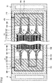
- Fig. 2 is a sectional view taken along the line II-II in Fig. 1 .
- Battery pack 1 is mounted on, for example, an electric-powered vehicle such as a battery electric vehicle.
- battery pack 1 includes a power storage device 10 and a cooling device 20.
- Cooling device 20 is a device that cools power storage device 10. Cooling device 20 is placed to be in contact with a lateral portion of power storage device 10. As shown in Fig. 1 , cooling device 20 is configured to allow a cooling medium (such as water) C to flow therein. Fig. 1 shows a state in which a part of cooling device 20 is missing.
- power storage device 10 includes a pair of external terminals 11, 12. External terminal 11 is a positive electrode terminal, and external terminal 12 is a negative electrode terminal. As shown in Fig. 2 , power storage device 10 includes a power storage module 100, a case 200, an insulating sheet 300, and a filling portion 400.
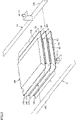
- Fig. 3 is an exploded perspective view schematically showing a configuration of a power storage module.
- power storage module 100 includes at least one power storage cell 101.
- power storage module 100 includes a plurality of power storage cells 101.
- Power storage cells 101 are stacked in one direction (the vertical direction in Fig. 1 ).
- Figs. 2 and 3 show three power storage cells 101, the number of power storage cells 101 is not particularly limited.
- An example of power storage cell 101 is a lithium ion battery.
- Power storage cell 101 is a so-called laminate-type cell. Specifically, power storage cell 101 includes a plurality of electrode bodies 110, a current collector plate 120, a laminated film 130, an adhesive member 140, and an electrolyte solution (not shown).
- Electrode bodies 110 are stacked in one direction. Electrode bodies 110 include a positive electrode sheet and a negative electrode sheet. A separator is placed between the positive electrode sheet and the negative electrode sheet. An end of each electrode body 110 is electrically connected to current collector plate 120.
- Laminated film 130 covers electrode bodies 110 and a part of current collector plate 120. Laminated film 130 is filled with an electrolyte solution (not shown).
- current collector plate 120 includes protrusions 122 protruding from laminated film 130. Protrusions 122 are connected to one another by a bus bar 102 such that power storage cells 101 are electrically connected in series.
- protrusion 122 of power storage cell 101 placed at an end on one side in a direction is connected with a bus bar 13 provided with external terminal 11
- protrusion 122 of power storage cell 101 placed at an end on the other side in the direction is connected with a bus bar 14 provided with external terminal 12.
- Adhesive member 140 is a member that bonds laminated film 130 to current collector plate 120.
- Adhesive member 140 is made of an insulating material (such as a resin).
- Adhesive member 140 is shaped to protrude from laminated film 130.
- adhesive member 140 includes a partly covering portion 142 (see Figs. 2 and 3 ) that covers a part of protrusion 122.
- Case 200 accommodates power storage module 100.
- Case 200 is made of a metal (such as aluminum).
- Case 200 includes a case body 210 and a closing plate 220, as shown in Fig. 1 .
- Case body 210 has an opening that opens in at least one direction.
- case body 210 is shaped into a square tube having a central axis extending in a direction orthogonal to a direction of stacking of power storage cells 101.
- Case body 210 is provided with an inlet h (see Fig. 2 ).
- Closing plate 220 is welded to case body 210 so as to close the opening of case body 210. Closing plate 220 is shaped into a flat plate.
- Cooling device 20 is provided to be in contact with an outer lateral surface of case body 210. In other words, cooling device 20 is provided to be in contact with case 200 in the direction orthogonal to the direction of stacking of power storage cells 101.
- Insulating sheet 300 covers an inner surface of case body 210 and an inner surface of closing plate 220. Insulating sheet 300 may cover an upper surface and a lower surface of case body 210, as shown in Fig. 2 .
- Filling portion 400 is made of an insulating material.
- filling portion 400 is made of a thermally conductive material.
- Filling portion 400 is formed by injecting the material (in the present embodiment, a potting material) into case 200 through inlet h of case 200.
- Filling portion 400 includes a tip covering portion 410 that covers the tip of protrusion 122, as shown in Fig. 2 .
- Tip covering portion 410 entirely covers protrusion 122 together with partly covering portion 142 of adhesive member 140.
- partly covering portion 142 and tip covering portion 410 constitute a covering portion 15 (see Fig. 2 ) that covers protrusion 122.
- Filling portion 400 may cover partly covering portion 142.
- filling portion 400 entirely covers bus bars 102, 13, 14.
- filling portion 400 is in contact with insulating sheet 300 provided on the inner surface of case body 210 and insulating sheet 300 provided on the inner surface of closing plate 220. As a result, a relative displacement of power storage module 100 to case 200 is reduced.
- power storage device 10 may further include a restriction unit 500.
- Restriction unit 500 is placed between power storage module 100 and case body 210. Restriction unit 500 may be placed between a pair of power storage cells 101 adjacent to each other.
- Restriction unit 500 restricts a relative displacement of power storage module 100 to case 200 in the direction of stacking of power storage cells 101.
- Restriction unit 500 is made of, for example, a material having dilatancy characteristics. Specifically, when each power storage cell 101 is displaced relative to case 200 in the direction of stacking at a low speed, such as when each power storage cell 101 expands, restriction unit 500 elastically deforms to absorb the expansion of each power storage cell 101. On the other hand, when each power storage cell 101 is displaced relative to case 200 in the direction of stacking at a relatively high speed, such as when power storage device 10 vibrates, restriction unit 500 exhibits a relatively high modulus of elasticity, thereby restricting a relative displacement of each power storage cell 101 to case 200. This reduces resonance of power storage module 100 when power storage device 10 vibrates.
- protrusion 122 of current collector plate 120 protruding from laminated film 130, is covered by covering portion 15. Even when the electrolyte solution leaks out of laminated film 130, thus, a short circuit between power storage cells 101 is reduced.
- current collector plate 120 and bus bar 102 are cooled by cooling device 20 via filling portion 400 made of a thermally conductive material from the lateral portion of case 200 in the direction orthogonal to the direction of stacking.
- Current collector plate 120 and bus bar 102 are made of metal, and accordingly, power storage module 100 is cooled effectively.
- covering portion 15 is not limited thereto.
- adhesive member 140 may not protrude from laminated film 130, and filling portion 400 may entirely cover protrusion 122. In this case, a part of filling portion 400 forms covering portion 15. Alternatively, in this case, filling portion 400 may cover an end of laminated film 130.
- a power storage device in the embodiment described above includes a plurality of power storage cells, a case for accommodating the plurality of power storage cells, and a covering portion made of an insulating material and covering a part of each of the plurality of power storage cells.
- Each of the plurality of power storage cells includes a plurality of electrode bodies, a current collector plate connected to the plurality of electrode bodies, a laminated film covering the plurality of electrode bodies and a part of the current collector plate, and an electrolyte solution filling the laminated film.
- the current collector plate includes a protrusion protruding from the laminated film.
- the covering portion covers the protrusion.
- the power storage device may further include an insulating sheet covering an inner surface of the case.
- the power storage device may further include a filling portion made of an insulating material and filling the case.
- each of the plurality of power storage cells further includes an adhesive member for bonding the laminated film to the current collector plate, the adhesive member includes a partly covering portion covering a part of the protrusion, the filling portion includes a tip covering portion covering a tip of the protrusion, and the partly covering portion and the tip covering portion constitute the covering portion.
Landscapes
- Chemical & Material Sciences (AREA)
- Chemical Kinetics & Catalysis (AREA)
- Electrochemistry (AREA)
- General Chemical & Material Sciences (AREA)
- Engineering & Computer Science (AREA)
- Manufacturing & Machinery (AREA)
- Battery Mounting, Suspending (AREA)
- Sealing Battery Cases Or Jackets (AREA)
- Connection Of Batteries Or Terminals (AREA)
Abstract
A power storage device (1) includes a plurality of power storage cells (101), a case (200) for accommodating the plurality of power storage cells, and a covering portion (15) made of an insulating material and covering a part of each of the plurality of power storage cells. Each power storage cell (101) includes a plurality of electrode bodies (110), a current collector plate (120) connected to the plurality of electrode bodies, a laminated film (130) covering the plurality of electrode bodies and a part of the current collector plate, and an electrolyte solution filling the laminated film. The current collector plate (120) includes a protrusion (122) protruding from the laminated film. The covering portion (15) covers the protrusion (122).
Description
- This nonprovisional application is based on
Japanese Patent Application No. 2021-060587 filed on March 31, 2021 - The present disclosure relates to a power storage device.
- A power storage device including a plurality of power storage cells has conventionally been known. For example,
Japanese Patent Laying-Open No. 2013-229266 - In the battery module disclosed in
Japanese Patent Laying-Open No. 2013-229266 - An object of the present disclosure is to provide a power storage device that can reduce the occurrence of a short circuit when an electrolyte solution leaks out of a laminated film.
- A power storage device according to an aspect of the present disclosure includes a plurality of power storage cells, a case for accommodating the plurality of power storage cells, and a covering portion made of an insulating material and covering a part of each of the plurality of power storage cells. Each of the plurality of power storage cells includes a plurality of electrode bodies, a current collector plate connected to the plurality of electrode bodies, a laminated film covering the plurality of electrode bodies and a part of the current collector plate, and an electrolyte solution filling the laminated film. The current collector plate includes a protrusion protruding from the laminated film. The covering portion covers the protrusion.
- The foregoing and other objects, features, aspects and advantages of the present disclosure will become more apparent from the following detailed description of the present disclosure when taken in conjunction with the accompanying drawings.
-
-
Fig. 1 is a perspective view schematically showing a configuration of a battery pack including a power storage device according to an embodiment of the present disclosure. -
Fig. 2 is a sectional view taken along the line II-II inFig. 1 . -
Fig. 3 is an exploded perspective view schematically showing a configuration of a power storage module. - An embodiment of the present disclosure will be described with reference to the drawings. The same or corresponding elements in the drawings have the same reference characters allotted in the figures referenced below.
-
Fig. 1 is a perspective view schematically showing a configuration of a battery pack including a power storage device of an embodiment of the present disclosure.Fig. 2 is a sectional view taken along the line II-II inFig. 1 . Battery pack 1 is mounted on, for example, an electric-powered vehicle such as a battery electric vehicle. - As shown in
Figs. 1 and2 , battery pack 1 includes apower storage device 10 and acooling device 20.Cooling device 20 is a device that coolspower storage device 10.Cooling device 20 is placed to be in contact with a lateral portion ofpower storage device 10. As shown inFig. 1 ,cooling device 20 is configured to allow a cooling medium (such as water) C to flow therein.Fig. 1 shows a state in which a part ofcooling device 20 is missing. - As shown in
Fig. 1 ,power storage device 10 includes a pair ofexternal terminals External terminal 11 is a positive electrode terminal, andexternal terminal 12 is a negative electrode terminal. As shown inFig. 2 ,power storage device 10 includes apower storage module 100, acase 200, aninsulating sheet 300, and afilling portion 400. -
Fig. 3 is an exploded perspective view schematically showing a configuration of a power storage module. As shown inFigs. 2 and3 ,power storage module 100 includes at least onepower storage cell 101. In the present embodiment,power storage module 100 includes a plurality ofpower storage cells 101.Power storage cells 101 are stacked in one direction (the vertical direction inFig. 1 ). AlthoughFigs. 2 and3 show threepower storage cells 101, the number ofpower storage cells 101 is not particularly limited. An example ofpower storage cell 101 is a lithium ion battery. -
Power storage cell 101 is a so-called laminate-type cell. Specifically,power storage cell 101 includes a plurality ofelectrode bodies 110, acurrent collector plate 120, a laminatedfilm 130, anadhesive member 140, and an electrolyte solution (not shown). -
Electrode bodies 110 are stacked in one direction.Electrode bodies 110 include a positive electrode sheet and a negative electrode sheet. A separator is placed between the positive electrode sheet and the negative electrode sheet. An end of eachelectrode body 110 is electrically connected tocurrent collector plate 120. - Laminated
film 130 coverselectrode bodies 110 and a part ofcurrent collector plate 120. Laminatedfilm 130 is filled with an electrolyte solution (not shown). - As shown in
Figs. 2 and3 ,current collector plate 120 includesprotrusions 122 protruding from laminatedfilm 130.Protrusions 122 are connected to one another by abus bar 102 such thatpower storage cells 101 are electrically connected in series. - As shown in
Fig. 3 ,protrusion 122 ofpower storage cell 101 placed at an end on one side in a direction is connected with abus bar 13 provided withexternal terminal 11, andprotrusion 122 ofpower storage cell 101 placed at an end on the other side in the direction is connected with abus bar 14 provided withexternal terminal 12. -
Adhesive member 140 is a member that bonds laminatedfilm 130 tocurrent collector plate 120.Adhesive member 140 is made of an insulating material (such as a resin).Adhesive member 140 is shaped to protrude from laminatedfilm 130. Specially,adhesive member 140 includes a partly covering portion 142 (seeFigs. 2 and3 ) that covers a part ofprotrusion 122. -
Case 200 accommodatespower storage module 100.Case 200 is made of a metal (such as aluminum).Case 200 includes acase body 210 and aclosing plate 220, as shown inFig. 1 . -
Case body 210 has an opening that opens in at least one direction. In the present embodiment,case body 210 is shaped into a square tube having a central axis extending in a direction orthogonal to a direction of stacking ofpower storage cells 101.Case body 210 is provided with an inlet h (seeFig. 2 ). - Closing
plate 220 is welded tocase body 210 so as to close the opening ofcase body 210. Closingplate 220 is shaped into a flat plate. -
Cooling device 20 is provided to be in contact with an outer lateral surface ofcase body 210. In other words,cooling device 20 is provided to be in contact withcase 200 in the direction orthogonal to the direction of stacking ofpower storage cells 101. - Insulating
sheet 300 covers an inner surface ofcase body 210 and an inner surface of closingplate 220. Insulatingsheet 300 may cover an upper surface and a lower surface ofcase body 210, as shown inFig. 2 . - Filling
portion 400 is made of an insulating material. Preferably, fillingportion 400 is made of a thermally conductive material. Fillingportion 400 is formed by injecting the material (in the present embodiment, a potting material) intocase 200 through inlet h ofcase 200. - Filling
portion 400 includes atip covering portion 410 that covers the tip ofprotrusion 122, as shown inFig. 2 .Tip covering portion 410 entirely coversprotrusion 122 together with partly coveringportion 142 ofadhesive member 140. Specifically, partly coveringportion 142 andtip covering portion 410 constitute a covering portion 15 (seeFig. 2 ) that coversprotrusion 122. Fillingportion 400 may cover partly coveringportion 142. - Preferably, filling
portion 400 entirely coversbus bars portion 400 is in contact with insulatingsheet 300 provided on the inner surface ofcase body 210 and insulatingsheet 300 provided on the inner surface of closingplate 220. As a result, a relative displacement ofpower storage module 100 tocase 200 is reduced. - As shown in
Fig. 2 ,power storage device 10 may further include arestriction unit 500.Restriction unit 500 is placed betweenpower storage module 100 andcase body 210.Restriction unit 500 may be placed between a pair ofpower storage cells 101 adjacent to each other. -
Restriction unit 500 restricts a relative displacement ofpower storage module 100 tocase 200 in the direction of stacking ofpower storage cells 101.Restriction unit 500 is made of, for example, a material having dilatancy characteristics. Specifically, when eachpower storage cell 101 is displaced relative tocase 200 in the direction of stacking at a low speed, such as when eachpower storage cell 101 expands,restriction unit 500 elastically deforms to absorb the expansion of eachpower storage cell 101. On the other hand, when eachpower storage cell 101 is displaced relative tocase 200 in the direction of stacking at a relatively high speed, such as whenpower storage device 10 vibrates,restriction unit 500 exhibits a relatively high modulus of elasticity, thereby restricting a relative displacement of eachpower storage cell 101 tocase 200. This reduces resonance ofpower storage module 100 whenpower storage device 10 vibrates. - As described above, in
power storage device 10 of the present embodiment,protrusion 122 ofcurrent collector plate 120, protruding fromlaminated film 130, is covered by coveringportion 15. Even when the electrolyte solution leaks out oflaminated film 130, thus, a short circuit betweenpower storage cells 101 is reduced. - In the present embodiment,
current collector plate 120 andbus bar 102 are cooled by coolingdevice 20 via fillingportion 400 made of a thermally conductive material from the lateral portion ofcase 200 in the direction orthogonal to the direction of stacking.Current collector plate 120 andbus bar 102 are made of metal, and accordingly,power storage module 100 is cooled effectively. - Although the embodiment described above has illustrated the example in which partly covering
portion 142 andtip covering portion 410 constitute coveringportion 15, the configuration of coveringportion 15 is not limited thereto. For example,adhesive member 140 may not protrude fromlaminated film 130, and fillingportion 400 may entirely coverprotrusion 122. In this case, a part of fillingportion 400forms covering portion 15. Alternatively, in this case, fillingportion 400 may cover an end oflaminated film 130. - It will be appreciated by a person skilled in the art that the exemplary embodiment described above provides specific examples of the following aspects.
- A power storage device in the embodiment described above includes a plurality of power storage cells, a case for accommodating the plurality of power storage cells, and a covering portion made of an insulating material and covering a part of each of the plurality of power storage cells. Each of the plurality of power storage cells includes a plurality of electrode bodies, a current collector plate connected to the plurality of electrode bodies, a laminated film covering the plurality of electrode bodies and a part of the current collector plate, and an electrolyte solution filling the laminated film. The current collector plate includes a protrusion protruding from the laminated film. The covering portion covers the protrusion.
- In this power storage device, since the protrusion of the current collector plate, protruding from the laminated film, is covered by the covering portion, a short circuit between the power storage cells is reduced even when the electrolyte solution leaks out of the laminated film.
- The power storage device may further include an insulating sheet covering an inner surface of the case.
- Thus, even when the electrolyte solution leaks out of the laminated film, the case and the power storage cell are restrained from becoming conductive via the electrolyte solution.
- The power storage device may further include a filling portion made of an insulating material and filling the case. Preferably, each of the plurality of power storage cells further includes an adhesive member for bonding the laminated film to the current collector plate, the adhesive member includes a partly covering portion covering a part of the protrusion, the filling portion includes a tip covering portion covering a tip of the protrusion, and the partly covering portion and the tip covering portion constitute the covering portion.
- Although the present disclosure has been described and illustrated in detail, it is clearly understood that the same is by way of illustration and example only and is not to be taken by way of limitation, the scope of the present disclosure being interpreted by the terms of the appended claims.
Claims (3)
- A power storage device (1) comprising:a plurality of power storage cells (101);a case (200) for accommodating the plurality of power storage cells; anda covering portion (15) made of an insulating material and covering a part of each of the plurality of power storage cells,each of the plurality of power storage cells (101) includinga plurality of electrode bodies (110),a current collector plate (120) connected to the plurality of electrode bodies,a laminated film (130) covering the plurality of electrode bodies and a part of the current collector plate, andan electrolyte solution filling the laminated film,the current collector plate (120) including a protrusion (122) protruding from the laminated film,the covering portion (15) covering the protrusion (122).
- The power storage device according to claim 1, further comprising an insulating sheet (300) covering an inner surface of the case.
- The power storage device according to claim 1 or 2, further comprising a filling portion (400) made of an insulating material and filling the case, whereineach of the plurality of power storage cells (101) further includes an adhesive member (140) for bonding the laminated film to the current collector plate,the adhesive member (140) includes a partly covering portion (142) covering a part of the protrusion,the filling portion (400) includes a tip covering portion (410) covering a tip of the protrusion, andthe partly covering portion (142) and the tip covering portion (410) constitute the covering portion (15).
Applications Claiming Priority (1)
| Application Number | Priority Date | Filing Date | Title |
|---|---|---|---|
| JP2021060587A JP7380629B2 (en) | 2021-03-31 | 2021-03-31 | assembled battery |
Publications (1)
| Publication Number | Publication Date |
|---|---|
| EP4068476A1 true EP4068476A1 (en) | 2022-10-05 |
Family
ID=80930291
Family Applications (1)
| Application Number | Title | Priority Date | Filing Date |
|---|---|---|---|
| EP22163721.8A Pending EP4068476A1 (en) | 2021-03-31 | 2022-03-23 | Power storage device |
Country Status (5)
| Country | Link |
|---|---|
| US (1) | US20220320627A1 (en) |
| EP (1) | EP4068476A1 (en) |
| JP (1) | JP7380629B2 (en) |
| KR (1) | KR102793768B1 (en) |
| CN (1) | CN115149224B (en) |
Families Citing this family (1)
| Publication number | Priority date | Publication date | Assignee | Title |
|---|---|---|---|---|
| JP2026013501A (en) * | 2024-07-17 | 2026-01-29 | 株式会社豊田自動織機 | Energy storage module |
Citations (6)
| Publication number | Priority date | Publication date | Assignee | Title |
|---|---|---|---|---|
| EP1294032A2 (en) * | 2001-09-17 | 2003-03-19 | Nissan Motor Co., Ltd. | Assembled battery |
| EP1744384A1 (en) * | 2004-04-28 | 2007-01-17 | Toyota Jidosha Kabushiki Kaisha | Laminate type secondary battery and battery pack thereof |
| JP2013229266A (en) | 2012-04-27 | 2013-11-07 | Automotive Energy Supply Corp | Battery pack |
| WO2016067487A1 (en) * | 2014-10-30 | 2016-05-06 | 三洋電機株式会社 | Power supply device |
| WO2019120806A1 (en) * | 2017-12-18 | 2019-06-27 | Hilti Aktiengesellschaft | Battery pack for a hand-held power tool |
| JP2021060587A (en) | 2015-12-01 | 2021-04-15 | Agc株式会社 | Video display system |
Family Cites Families (16)
| Publication number | Priority date | Publication date | Assignee | Title |
|---|---|---|---|---|
| JP5000799B2 (en) * | 1999-12-24 | 2012-08-15 | 古河電池株式会社 | Lead acid battery |
| JP2001256960A (en) * | 2000-03-10 | 2001-09-21 | Mitsubishi Chemicals Corp | Battery |
| JP3829630B2 (en) * | 2001-02-09 | 2006-10-04 | 三菱化学株式会社 | Secondary battery |
| US8173294B2 (en) * | 2009-04-28 | 2012-05-08 | Lightening Energy | High voltage modular battery with electrically-insulated cell module and interconnector peripheries |
| JP2013051100A (en) * | 2011-08-31 | 2013-03-14 | Nissan Motor Co Ltd | Battery temperature control module |
| CN103138027A (en) * | 2011-11-30 | 2013-06-05 | 庄嘉明 | High thermal conductivity battery components |
| JP2013134818A (en) * | 2011-12-26 | 2013-07-08 | Showa Denko Kk | Terminal lead |
| JP2014093239A (en) * | 2012-11-06 | 2014-05-19 | Nissan Motor Co Ltd | Battery module |
| US20150140400A1 (en) * | 2013-11-15 | 2015-05-21 | Semiconductor Energy Laboratory Co., Ltd. | Power storage unit and electronic device including the same |
| PL3051611T3 (en) * | 2013-11-26 | 2020-05-18 | Lg Chem, Ltd. | Battery cell comprising means for protecting short circuit |
| KR101941117B1 (en) * | 2015-02-27 | 2019-01-23 | 주식회사 엘지화학 | Battery module |
| KR102172515B1 (en) * | 2016-03-16 | 2020-10-30 | 주식회사 엘지화학 | Battery module |
| DE102017201692A1 (en) * | 2017-02-02 | 2018-08-02 | Robert Bosch Gmbh | Battery module with a plurality of battery cells and battery |
| KR102264635B1 (en) * | 2017-11-23 | 2021-06-15 | 주식회사 엘지에너지솔루션 | The Pouch Type Secondary Battery |
| WO2021117584A1 (en) * | 2019-12-13 | 2021-06-17 | 京セラ株式会社 | Electrochemical cell and electrochemical cell module |
| JP6842097B1 (en) * | 2020-03-17 | 2021-03-17 | 株式会社ヤハタ | Power storage module |
-
2021
- 2021-03-31 JP JP2021060587A patent/JP7380629B2/en active Active
-
2022
- 2022-03-03 US US17/685,958 patent/US20220320627A1/en not_active Abandoned
- 2022-03-23 EP EP22163721.8A patent/EP4068476A1/en active Pending
- 2022-03-28 CN CN202210313068.XA patent/CN115149224B/en active Active
- 2022-03-29 KR KR1020220039038A patent/KR102793768B1/en active Active
Patent Citations (6)
| Publication number | Priority date | Publication date | Assignee | Title |
|---|---|---|---|---|
| EP1294032A2 (en) * | 2001-09-17 | 2003-03-19 | Nissan Motor Co., Ltd. | Assembled battery |
| EP1744384A1 (en) * | 2004-04-28 | 2007-01-17 | Toyota Jidosha Kabushiki Kaisha | Laminate type secondary battery and battery pack thereof |
| JP2013229266A (en) | 2012-04-27 | 2013-11-07 | Automotive Energy Supply Corp | Battery pack |
| WO2016067487A1 (en) * | 2014-10-30 | 2016-05-06 | 三洋電機株式会社 | Power supply device |
| JP2021060587A (en) | 2015-12-01 | 2021-04-15 | Agc株式会社 | Video display system |
| WO2019120806A1 (en) * | 2017-12-18 | 2019-06-27 | Hilti Aktiengesellschaft | Battery pack for a hand-held power tool |
Also Published As
| Publication number | Publication date |
|---|---|
| KR20220136231A (en) | 2022-10-07 |
| CN115149224B (en) | 2024-11-12 |
| CN115149224A (en) | 2022-10-04 |
| KR102793768B1 (en) | 2025-04-09 |
| JP2022156746A (en) | 2022-10-14 |
| JP7380629B2 (en) | 2023-11-15 |
| US20220320627A1 (en) | 2022-10-06 |
Similar Documents
| Publication | Publication Date | Title |
|---|---|---|
| CN111587496B (en) | Battery module including heat shrinkable tube | |
| KR101792675B1 (en) | Battery module | |
| EP3937299A1 (en) | Battery module and battery pack | |
| US8846221B2 (en) | Battery pack | |
| US11984612B2 (en) | Battery module comprising module housing | |
| EP4191750B1 (en) | Battery pack with improved cooling performance and device comprising same | |
| US12308455B2 (en) | Battery pack, electronic device and vehicle | |
| US12362435B2 (en) | Battery module comprising module bus bar, battery pack comprising same, and electronic device | |
| JP2011159474A (en) | Battery pack | |
| KR102057620B1 (en) | Battery module | |
| US12322817B2 (en) | Battery pack, and electronic device and vehicle including the same | |
| CN101393972A (en) | rechargeable battery pack | |
| EP4068476A1 (en) | Power storage device | |
| US12463278B2 (en) | Power storage device | |
| EP4024592A2 (en) | Battery module | |
| EP4432446B1 (en) | Battery module, and battery pack and vehicle including the same | |
| KR20220047057A (en) | Battery module and battery pack including the same and vehicle including the same | |
| CN120109338A (en) | Busbar bracket assembly, battery module including the same, and manufacturing method thereof | |
| US12412966B2 (en) | Power storage device | |
| US12347880B2 (en) | Power storage device and method of manufacturing power storage device | |
| CN222940163U (en) | Battery cells, battery modules and electrical equipment | |
| EP4625683A1 (en) | Battery module and battery pack comprising same | |
| KR100788558B1 (en) | Pack battery | |
| KR20260054750A (en) | Battery module and electronic device using the same | |
| CN120283333A (en) | Battery module and battery pack including the same |
Legal Events
| Date | Code | Title | Description |
|---|---|---|---|
| PUAI | Public reference made under article 153(3) epc to a published international application that has entered the european phase |
Free format text: ORIGINAL CODE: 0009012 |
|
| STAA | Information on the status of an ep patent application or granted ep patent |
Free format text: STATUS: REQUEST FOR EXAMINATION WAS MADE |
|
| 17P | Request for examination filed |
Effective date: 20220323 |
|
| AK | Designated contracting states |
Kind code of ref document: A1 Designated state(s): AL AT BE BG CH CY CZ DE DK EE ES FI FR GB GR HR HU IE IS IT LI LT LU LV MC MK MT NL NO PL PT RO RS SE SI SK SM TR |
|
| STAA | Information on the status of an ep patent application or granted ep patent |
Free format text: STATUS: EXAMINATION IS IN PROGRESS |
|
| 17Q | First examination report despatched |
Effective date: 20250117 |