EP4067936A1 - Solid-state radar device - Google Patents
Solid-state radar device Download PDFInfo
- Publication number
- EP4067936A1 EP4067936A1 EP20891123.0A EP20891123A EP4067936A1 EP 4067936 A1 EP4067936 A1 EP 4067936A1 EP 20891123 A EP20891123 A EP 20891123A EP 4067936 A1 EP4067936 A1 EP 4067936A1
- Authority
- EP
- European Patent Office
- Prior art keywords
- signal
- modulated signal
- pulse
- solid
- echo image
- Prior art date
- Legal status (The legal status is an assumption and is not a legal conclusion. Google has not performed a legal analysis and makes no representation as to the accuracy of the status listed.)
- Granted
Links
Images




Classifications
-
- G—PHYSICS
- G01—MEASURING; TESTING
- G01S—RADIO DIRECTION-FINDING; RADIO NAVIGATION; DETERMINING DISTANCE OR VELOCITY BY USE OF RADIO WAVES; LOCATING OR PRESENCE-DETECTING BY USE OF THE REFLECTION OR RERADIATION OF RADIO WAVES; ANALOGOUS ARRANGEMENTS USING OTHER WAVES
- G01S13/00—Systems using the reflection or reradiation of radio waves, e.g. radar systems; Analogous systems using reflection or reradiation of waves whose nature or wavelength is irrelevant or unspecified
- G01S13/88—Radar or analogous systems specially adapted for specific applications
- G01S13/95—Radar or analogous systems specially adapted for specific applications for meteorological use
- G01S13/956—Radar or analogous systems specially adapted for specific applications for meteorological use mounted on ship or other platform
-
- G—PHYSICS
- G01—MEASURING; TESTING
- G01S—RADIO DIRECTION-FINDING; RADIO NAVIGATION; DETERMINING DISTANCE OR VELOCITY BY USE OF RADIO WAVES; LOCATING OR PRESENCE-DETECTING BY USE OF THE REFLECTION OR RERADIATION OF RADIO WAVES; ANALOGOUS ARRANGEMENTS USING OTHER WAVES
- G01S13/00—Systems using the reflection or reradiation of radio waves, e.g. radar systems; Analogous systems using reflection or reradiation of waves whose nature or wavelength is irrelevant or unspecified
- G01S13/02—Systems using reflection of radio waves, e.g. primary radar systems; Analogous systems
- G01S13/06—Systems determining position data of a target
- G01S13/08—Systems for measuring distance only
- G01S13/10—Systems for measuring distance only using transmission of interrupted, pulse modulated waves
- G01S13/106—Systems for measuring distance only using transmission of interrupted, pulse modulated waves using transmission of pulses having some particular characteristics
-
- G—PHYSICS
- G01—MEASURING; TESTING
- G01S—RADIO DIRECTION-FINDING; RADIO NAVIGATION; DETERMINING DISTANCE OR VELOCITY BY USE OF RADIO WAVES; LOCATING OR PRESENCE-DETECTING BY USE OF THE REFLECTION OR RERADIATION OF RADIO WAVES; ANALOGOUS ARRANGEMENTS USING OTHER WAVES
- G01S13/00—Systems using the reflection or reradiation of radio waves, e.g. radar systems; Analogous systems using reflection or reradiation of waves whose nature or wavelength is irrelevant or unspecified
- G01S13/02—Systems using reflection of radio waves, e.g. primary radar systems; Analogous systems
- G01S13/06—Systems determining position data of a target
- G01S13/08—Systems for measuring distance only
- G01S13/10—Systems for measuring distance only using transmission of interrupted, pulse modulated waves
- G01S13/26—Systems for measuring distance only using transmission of interrupted, pulse modulated waves wherein the transmitted pulses use a frequency- or phase-modulated carrier wave
- G01S13/28—Systems for measuring distance only using transmission of interrupted, pulse modulated waves wherein the transmitted pulses use a frequency- or phase-modulated carrier wave with time compression of received pulses
- G01S13/282—Systems for measuring distance only using transmission of interrupted, pulse modulated waves wherein the transmitted pulses use a frequency- or phase-modulated carrier wave with time compression of received pulses using a frequency modulated carrier wave
-
- G—PHYSICS
- G01—MEASURING; TESTING
- G01S—RADIO DIRECTION-FINDING; RADIO NAVIGATION; DETERMINING DISTANCE OR VELOCITY BY USE OF RADIO WAVES; LOCATING OR PRESENCE-DETECTING BY USE OF THE REFLECTION OR RERADIATION OF RADIO WAVES; ANALOGOUS ARRANGEMENTS USING OTHER WAVES
- G01S13/00—Systems using the reflection or reradiation of radio waves, e.g. radar systems; Analogous systems using reflection or reradiation of waves whose nature or wavelength is irrelevant or unspecified
- G01S13/02—Systems using reflection of radio waves, e.g. primary radar systems; Analogous systems
- G01S13/06—Systems determining position data of a target
- G01S13/08—Systems for measuring distance only
- G01S13/10—Systems for measuring distance only using transmission of interrupted, pulse modulated waves
- G01S13/30—Systems for measuring distance only using transmission of interrupted, pulse modulated waves using more than one pulse per radar period
-
- G—PHYSICS
- G01—MEASURING; TESTING
- G01S—RADIO DIRECTION-FINDING; RADIO NAVIGATION; DETERMINING DISTANCE OR VELOCITY BY USE OF RADIO WAVES; LOCATING OR PRESENCE-DETECTING BY USE OF THE REFLECTION OR RERADIATION OF RADIO WAVES; ANALOGOUS ARRANGEMENTS USING OTHER WAVES
- G01S13/00—Systems using the reflection or reradiation of radio waves, e.g. radar systems; Analogous systems using reflection or reradiation of waves whose nature or wavelength is irrelevant or unspecified
- G01S13/88—Radar or analogous systems specially adapted for specific applications
- G01S13/89—Radar or analogous systems specially adapted for specific applications for mapping or imaging
-
- G—PHYSICS
- G01—MEASURING; TESTING
- G01S—RADIO DIRECTION-FINDING; RADIO NAVIGATION; DETERMINING DISTANCE OR VELOCITY BY USE OF RADIO WAVES; LOCATING OR PRESENCE-DETECTING BY USE OF THE REFLECTION OR RERADIATION OF RADIO WAVES; ANALOGOUS ARRANGEMENTS USING OTHER WAVES
- G01S7/00—Details of systems according to groups G01S13/00, G01S15/00, G01S17/00
- G01S7/02—Details of systems according to groups G01S13/00, G01S15/00, G01S17/00 of systems according to group G01S13/00
- G01S7/03—Details of HF subsystems specially adapted therefor, e.g. common to transmitter and receiver
- G01S7/032—Constructional details for solid-state radar subsystems
-
- G—PHYSICS
- G01—MEASURING; TESTING
- G01S—RADIO DIRECTION-FINDING; RADIO NAVIGATION; DETERMINING DISTANCE OR VELOCITY BY USE OF RADIO WAVES; LOCATING OR PRESENCE-DETECTING BY USE OF THE REFLECTION OR RERADIATION OF RADIO WAVES; ANALOGOUS ARRANGEMENTS USING OTHER WAVES
- G01S7/00—Details of systems according to groups G01S13/00, G01S15/00, G01S17/00
- G01S7/02—Details of systems according to groups G01S13/00, G01S15/00, G01S17/00 of systems according to group G01S13/00
- G01S7/28—Details of pulse systems
- G01S7/285—Receivers
- G01S7/288—Coherent receivers
- G01S7/2883—Coherent receivers using FFT processing
-
- G—PHYSICS
- G01—MEASURING; TESTING
- G01S—RADIO DIRECTION-FINDING; RADIO NAVIGATION; DETERMINING DISTANCE OR VELOCITY BY USE OF RADIO WAVES; LOCATING OR PRESENCE-DETECTING BY USE OF THE REFLECTION OR RERADIATION OF RADIO WAVES; ANALOGOUS ARRANGEMENTS USING OTHER WAVES
- G01S7/00—Details of systems according to groups G01S13/00, G01S15/00, G01S17/00
- G01S7/02—Details of systems according to groups G01S13/00, G01S15/00, G01S17/00 of systems according to group G01S13/00
- G01S7/41—Details of systems according to groups G01S13/00, G01S15/00, G01S17/00 of systems according to group G01S13/00 using analysis of echo signal for target characterisation; Target signature; Target cross-section
- G01S7/411—Identification of targets based on measurements of radar reflectivity
-
- G—PHYSICS
- G01—MEASURING; TESTING
- G01S—RADIO DIRECTION-FINDING; RADIO NAVIGATION; DETERMINING DISTANCE OR VELOCITY BY USE OF RADIO WAVES; LOCATING OR PRESENCE-DETECTING BY USE OF THE REFLECTION OR RERADIATION OF RADIO WAVES; ANALOGOUS ARRANGEMENTS USING OTHER WAVES
- G01S7/00—Details of systems according to groups G01S13/00, G01S15/00, G01S17/00
- G01S7/02—Details of systems according to groups G01S13/00, G01S15/00, G01S17/00 of systems according to group G01S13/00
- G01S7/04—Display arrangements
- G01S7/06—Cathode-ray tube displays or other two dimensional or three-dimensional displays
- G01S7/10—Providing two-dimensional [2D] co-ordinated display of distance and direction
- G01S7/18—Distance-height displays; Distance-elevation displays, e.g. type RHI, type E
-
- H—ELECTRICITY
- H01—ELECTRIC ELEMENTS
- H01Q—ANTENNAS, i.e. RADIO AERIALS
- H01Q3/00—Arrangements for changing or varying the orientation or the shape of the directional pattern of the waves radiated from an antenna or antenna system
- H01Q3/02—Arrangements for changing or varying the orientation or the shape of the directional pattern of the waves radiated from an antenna or antenna system using mechanical movement of antenna or antenna system as a whole
- H01Q3/08—Arrangements for changing or varying the orientation or the shape of the directional pattern of the waves radiated from an antenna or antenna system using mechanical movement of antenna or antenna system as a whole for varying two co-ordinates of the orientation
Definitions
- the disclosure relates to a solid-state radar device and a radar control method and a radar control system thereof.
- the solid-state radars Compared to the magnetron radars, solid-state radars, whose development started in rather recent years, use semiconductors as transmission elements, and have the advantages of having a narrow bandwidth, a miniaturized size, and being maintenance-free.
- the transmission peak power of a solid-state radar is far lower than the transmission peak power of a magnetron radar. Therefore, in order to observe a remote target, the solid-state radar may transmit a pulse-like signal whose frequency is modulated (chirped pulse signal) to pulse-compress waves reflected from the target and improve the S/N ratio.
- the radars for ships are also used to observe waves in the periphery of the own ship, in addition to monitoring the periphery of the own ship, and are referred to as wave radars for wave observation.
- the wave radars analyze the reflected waves of the transmission signals returned from the sea level in the periphery of the own ship, and output wave information, such as wave heights, periods, wavelengths, wave directions, etc., of the waves.
- wave radars have been developed by using magnetron radars.
- a transmission signal is set as a non-modulated signal (long pulse) composed of a long pulse width for long distance observation.
- transmission signals are mostly set as non-modulated signals (short-pulse or middle-pulse) of a short pulse width for short distance to intermediate distance observation. Therefore, in the case where wave observation and periphery monitoring are performed at the same time by using short pulse or middle pulse signals in the transmission signals, the magnetron radar is unable to observe a remote target. As a result, the magnetron radar is unable to sufficiently fulfill the purpose of periphery monitoring.
- a user who performs periphery monitoring including remote monitoring in wave observation needs to be respectively provided with a radar for wave observation and a radar for target observation.
- the purpose of the disclosure relates to providing a solid-state radar device capable of fulfilling the functions of wave observation as well as periphery monitoring including remote monitoring at the same time.
- a solid-state radar device includes: a transmission/reception unit, transmitting and receiving radio wave signals comprising a modulated signal and a non-modulated signal, which are pulse signals whose frequencies are different from each other; a frequency filter unit, respectively extracting the modulated signal and the non-modulated signal based on the frequencies from the received radio wave signals; a pulse compression unit, generating a pulse-compressed signal obtained by subjecting the modulated signal to pulse compression; a first echo image generation unit, generating a first echo image based on the non-modulated signal and the pulse-compressed signal; a wave analysis unit, calculating an analysis result of wave information based on one of the non-modulated signal and the pulse-compressed signal; and a display signal generation unit, generating a display signal of the first echo image and the analysis result.
- a period for calculating the analysis result may be longer.
- the transmission/reception unit may further include an antenna that rotates, and the wave analysis unit may calculate the analysis result by analyzing a scan image composed of the first echo image corresponding to one rotation of the antenna.
- the first echo image may be divided into a plurality of regions in accordance with a distance from a transmission location, and the regions may be formed from an image based on at least one of the non-modulated signal and the pulse-compressed signal.
- the wave analysis unit may analyze, among the regions, a region formed by one of the non-modulated signal and the pulse-compressed signal.
- At least one of the regions may be formed from a synthesized image in which a formation ratio of the non-modulated signal and the pulse-compressed signal is changed in accordance with distance.
- the display signal generation unit may generate a display signal in which the first echo image and the analysis result are displayed at a same time on a same screen.
- the display signal generation unit may generate a display signal in which information of at least a portion of the analysis result is superimposed on the first echo image.
- the display signal generation unit may generate a display signal in which an analysis region, which is a region for analyzing the wave information, is superimposed on the first echo image.
- the solid-state radar device may further include an analysis region input unit, receiving an input, from a user, for changing at least one of a number, a location, and a size of the analysis region.
- the solid-state radar device may further include: a heading acquisition unit, calculating a heading of an own ship.
- the analysis result may include information of a wave direction.
- the display signal generation unit may generate a display signal indicating a relative angle between the wave direction and the heading.
- the display signal generation unit may generate a display signal of a wave image based on the analysis result.
- the solid-state radar device may further include: a second echo image generation unit, generating a second echo image based on one of the non-modulated signal and the pulse-compressed signal.
- the wave analysis unit may calculate the analysis result by analyzing a region of a portion of the second echo image.
- the transmission/reception unit may further include an antenna that rotates, and the wave analysis unit may calculate the analysis result by analyzing a scan image composed of the second echo image corresponding to one rotation of the antenna.
- the solid-state radar device by transmitting the radio wave signals whose frequencies are different and respectively separating the radio wave signals from reflected waves, it is possible for the solid-state radar device to fulfill wave observation and monitoring at the same time.
- a solid-state radar device according to the embodiment of the disclosure is described with reference to the drawings.
- the solid-state radar device in the embodiment is used as a radar for a ship, such as a merchant ship, a fishing ship, a pleasure boat, etc.
- FIG. 1 is a diagram illustrating the configuration of a solid-state radar device 101 according to the embodiment.
- FIG. 2 illustrates the configuration of a transmission/reception unit 10.
- the transmission/reception unit 10 is formed by an antenna 11, a circulator 12, a transmission unit 13, and a reception unit 14, etc.
- the transmission unit 13 alternately generates, as transmission signals, a modulated signal, which is a pulse signal whose frequency is modulated, and a non-modulated signal, which is a non-modulated pulse signal, and outputs the transmission signals to the circulator 12. At this time, the transmission unit 13 generates, as the transmission signals whose frequencies are different, the modulated signal and the non-modulated signal, so that the frequency bands do not overlap each other. In addition, while not shown in the drawings, the transmission unit 13 outputs a portion of the transmission signal relating to the modulated signal to a pulse compression unit 30.
- the circulator 12 transmits the transmission signals from the transmission unit 13 to the antenna 11, and outputs reception signals received from the antenna 11 to the reception unit 14.
- the antenna 11 is formed by arranging patch antennas, etc., in a row, and rotates thereby being able to orientate a transmission/reception surface in all directions (360 degrees) of a parallel surface with respect to a surface where the solid-state radar device 101 is disposed.
- the antenna 11 radiates the transmission signals with respect to an external space in various azimuths while rotating. A portion of the transmitted transmission signals is reflected by a reflection body such as an object, etc., present at sea level or in the sea.
- the antenna 11 receives, as the reception signals, a portion of the transmission signals that are reflected while rotating.
- the reception unit 14 performs a reception process detecting the reception signals by using a double superheterodyne method and, after amplification by an amplifier, converting analog signals into digital signals by using an A/D converter.
- FIG. 3 illustrates the configuration of a frequency filter unit 20.
- the frequency filter unit 20 is composed of two band-pass filters (BPF) separating the modulated signal and the non-modulated signal based on frequencies.
- BPF band-pass filters
- the reception signals subjected to the reception process in the reception unit 14 are respectively output to a BPF 21 and a BPF 22.
- the BPF 21 extracts the one with a lower frequency between the modulated signal and the non-modulated signal
- the BPF 22 extracts the other one with a higher frequency.
- whether each of the BPF 21 and the BPF 22 extracts the modulated signal and the non-modulated signal depends on the setting of the frequencies of the modulated signal and the non-modulated signal.
- the two band-pass filters may also be formed from a low-pass filter (LPF) and a high-pass filter (HPF), as long as the filters are able to separate the modulated signal and the non-modulated signal.
- LPF low-pass filter
- HPF high-pass filter
- the modulated signal extracted by one of the band-pass filters is output to the pulse compression unit 30.
- the non-modulated signal extracted by the other of the band-pass filters is output to a first echo image generation unit 40.
- the pulse compression unit 30 converts the modulated signal into a pulse-compressed signal by performing a pulse compression process, and outputs the pulse-compressed signal to the first echo image generation unit 40.
- the pulse compression process may be a conventionally known process, such as a matched filter method.
- the first echo image generation unit 40 generates, as a first echo image, a sweep image based on sweep data, and outputs the sweep image to a wave analysis unit 50 and a display signal generation unit 60.
- the sweep data is the signal data of a specific direction generated from the non-modulated signal and the pulse-compressed signal corresponding to consecutive transmission pulses.
- the sweep image is an image in which the distance from an own ship 70 to a particular distance is pixelated based on the sweep data of the modulated signal, and a distance that is further is pixelated based on the sweep data of the pulse-compressed signal, the azimuth direction being one pixel, and the distance direction being a particular number of pixels.
- the wave analysis unit 50 generates an image of one polar coordinate system from multiple sweep images equivalent to one scan.
- the wave analysis unit 50 converts the image of the polar coordinate system into one scan image, which is an image of a Cartesian coordinate system with the own ship 70 being at the center.
- scan refers to an operation of rotating the antenna 360 degrees while performing transmission/reception of radio wave signals.
- Radio wave signals are a general term referring to the transmission signal and the reception signal, which is the modulated signal or the non-modulated signal, and the reflected waves of the transmission signal.
- the wave analysis unit 50 sets an analysis region 71, which is a portion of the region of the same pixel size, from a region of the area generated by the non-modulated signals or the pulse-compressed signals of multiple scan images that are consecutive in time.
- FIG. 4 is an example in which the analysis region 71 is set in a region composed of the non-modulated signal in one scan image.
- the intensity information of multiple images corresponding to the location of the analysis region 71 is handled as a three-dimensional matrix.
- the wave analysis unit 50 calculates, as an analysis result, wave information such as the wave height, the period, the wavelength, and the direction, etc., based on the result of a Fourier conversion on the three-dimensional matrix, and outputs the analysis result to the display signal generation unit 60.
- the period for calculating the analysis result is longer than the period for generating the sweep image.
- the display signal generation unit 60 generates a display signal of a screen containing the sweep image and the wave analysis result.
- the solid-state radar device 101 may further include a display unit displaying the display signal generated by the display signal generation unit 60.
- the transmission unit of the magnetron radar has a magnetron element, and can transmit a pulse signal with a high peak power with respect to a solid-state element of the solid-state radar. Meanwhile, due to the characteristics of the solid-state element, the peak power of the transmission signal is low, so the transmission unit of the solid-state radar cannot transmit a pulse signal with power equivalent to that of the magnetron radar. Therefore, the solid-state radar cannot secure a detection distance by using the same pulse width as the magnetron radar. Therefore, the transmission unit of the solid-state radar transmits a temporally long pulse signal (modulated signal) whose frequency is modulated, ensures the S/N ratio by performing the pulse compression process at the time of reception, and secures the detection distance.
- modulated signal modulated signal
- the solid-state radar during the transmission of the modulated signal, a portion of the transmission signal is leaked to the reception unit 14. Therefore, the solid-state radar cannot receive the reflected wave of the modulated signal during the transmission of the modulated signal. Since the modulated signal of the solid-state radar is based on the assumption that the S/N ratio improves due to the pulse compression process, the modulation signal of the solid-state radar is longer than the transmission signal of the magnetron radar. As a result, the time during which the solid-state radar cannot receive the modulated signal is longer, and such time becomes the time during which the target in the vicinity of the own ship cannot be observed. In the following, the region in which the reflected wave of the modulated signal cannot be received is referred to as a dead region. For example, in the case where the pulse width of the modulated signal is about 10 ⁇ s, the dead region is in a range with a radius of about 1500 m from the own ship.
- the solid-state radar transmits non-modulated signals whose averaged power is low and pulse width is short, and interpolates the dead region of the modulated signal by generating an echo image of the dead region based on the reception signals of the non-modulated signals.
- the solid-state radar can observe targets from the vicinity of the own ship to a remote location.
- the solid-state radar can set respectively different frequencies for the transmission signals of the modulated signal and the non-modulated signal, and the respective reception signals thereof can be easily separated by using the band-pass filters.
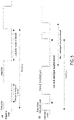
- the magnetron radar may serve as a combined radar for wave analysis and periphery monitoring. More specifically, as shown in (A) of FIG. 5 , the magnetron radar can analyze waves based on the reception signal of a short pulse and generate the echo image of a remote location based on the reception signal of a long pulse.
- the transmission unit may decrease the pulse repetition frequency (PRF), which is the frequency of repeating each transmission pulse.
- PRF pulse repetition frequency
- the decrease in PRF decreases the respective azimuth resolutions of the short pulse and the long pulse as well as the hit number of the target, leading, in particular, to a decrease in the ability of detecting a remote target.
- the solid-state radar may easily change the frequency of the transmission signal, so the solid-state radar can consecutively transmit the modulated signal and the non-modulated signal of different frequencies. Therefore, as shown in (B) of FIG. 5 , by separating the reception signals of the modulated signal and the non-modulated signal by using the band-pass filters, the other of the modulated signal and the non-modulated signal can be received during transmission of the other without the concern of leakage of the transmission signal. Accordingly, the solid-state radar does not need to decrease the PRF of the transmission signal.
- the wave analysis unit 50 of the embodiment calculates the analysis result by analyzing the region of a portion of the image composed of the first echo image generated in the first echo image generation unit 40. Therefore, it is not necessary for the transmission unit 10 to separately transmit the transmission signal used for analyzing the waves in the vicinity of the own ship and the transmission signal used for generating the display signal as the image of the periphery of the own ship. Accordingly, in the embodiment which analyzes the wave information, it is not necessary for the solid-state radar to decrease the PRF of the transmission signal.
- the wave analysis unit 50 analyzes the wave information in a region formed by one of the non-modulated signal and the pulse-compressed signal in the first echo image.
- the wave analysis unit 50 can analyze the wave information without generating another echo image for wave analysis. This is because the non-modulated signal and the pulse-compressed signal have different pulse properties, and the echo images respectively composed of the non-modulated signal and the pulse-compressed signal also have different properties.
- the pulse width of the non-modulated signal to a very short pulse width for the analysis on the wave information, the analysis result of the wave information becomes highly accurate.
- FIG. 6 which is the flowchart according to the embodiment of the disclosure, is described.
- the transmission/reception unit 10 generates the transmission signals of the modulated signal and the non-modulated signal (Step S1). Then, the transmission/reception unit 10 performs a transmission process which radiates the generated transmission signals to the external space via the circulator 12 and the rotating antenna 11 (Step S2). Then, the transmission/reception unit 10 performs a reception process which receives the reflected waves that are the transmission signals reflected from a reflection body via the antenna 11 (Step S3)
- the frequency filter 20 respectively extracts the modulated signal and the non-modulated signal from the reception signals by using the band-pass filters (Step S4).
- the frequency filter unit 20 outputs the modulated signal in the reception signals to the pulse compression unit 30 (Step S5). If the reception signal is not the modulated signal, that is, if the reception signal is the non-modulated signal, the frequency filter unit 20 inputs the reception signal to the first echo image generation unit 40 (Step S5).
- the pulse compression unit 30 performs a pulse compression process on the modulated signal, and outputs the pulse-compressed signal to the first echo image generation unit 40 (Step S6).
- the first echo image generation unit 40 generates an echo image based on the sweep data of the modulated signal and the non-modulated signal (Step S7). Then, in the case where the first echo image is used in the wave analysis unit 50, the first echo image generation unit 40 outputs the first echo image to the wave analysis unit 50 (Step S8). In addition, in the case where the first echo image is not used in the wave analysis unit 50, the second echo image generation unit 41 generates a second echo image, and outputs the second echo image to the wave analysis unit 50 (Step S9).
- the wave analysis unit 50 performs an analysis on the wave information based on at least one of the non-modulated signal and the pulse-compressed signal, and outputs a wave analysis result, such as the wave height, the period, the wavelength, and the direction to the display signal generation unit 60 (Step S10).
- the display signal generation unit 60 generates a display signal displaying the wave analysis result and the first echo image (Step S 11).
- the first echo image generation unit 40 can generate the first echo image by dividing into multiple regions with respect to the distance direction.
- the region in the vicinity of the own ship is formed by the non-modulated signal
- the remote region of the own ship is formed by the pulse-compressed signal.
- the wave analysis unit 50 sets the analysis region 70, among the regions, in the region formed by the non-modulated signal in the vicinity of the own ship, and analyzes the wave information.
- the first echo image generation unit 40 In the region due to synthesis in FIG. 7 , the first echo image generation unit 40 generates the first echo image having a region formed due to synthesis of the non-modulated signal and the pulse-compressed signal between the regions respectively formed by the non-modulated signal and the pulse-compressed signal among the multiple divided regions.
- the process for the synthesis is a process in which the formation ratio of the non-modulated signal decreases as the distance from the transmission/reception unit increases. Accordingly, the first echo image is a seamless image in which the joined part of the regions of the two signals is not prominent.
- a display screen 61 shown in FIG. 8 an image 62 of the periphery of the own ship based on the first echo image is provided on the left, and the information of the wave height, the period, and the wave direction, which is a portion of the analysis result, is provided in a wave information area 63 on the right, and the display screen 61 displays the periphery image 62 and the wave information area 63 on the same display screen at the same time.
- the display screen 61 superimposes the analysis region 71 on the periphery image 62 based on the first echo image.
- the display screen 61 displays a wave vector 73, which is a portion of the analysis result, on the periphery image 62.
- the display signal generation unit 60 can generate two types of display signals displaying the first echo image and the analysis result on two respectively different display screens.
- a solid-state radar device 102 in FIG. 9 further includes a heading acquisition unit 80.
- the heading acquisition unit 80 calculates the heading of the own ship from sensor information of a GPS sensor or a gyrocompass acquiring the location information of the own ship, and outputs the heading to the display signal generation unit 60.
- the display screen 61 in FIG. 8 is a screen displaying the information of a relative angle 72 between the wave direction, which is a portion of the wave analysis result, and the heading of the own ship.
- the wave analysis unit 50 may also perform a Fourier conversion on the three-dimensional matrix of the analysis region 71, and perform an inverse Fourier conversion after removing components other than waves through filtering based on the frequency of the waves of the analysis result, thereby generating, as a wave image, a two-dimensional image that emphasizes the wave information as compared to a normal echo.
- the wave image is a three-dimensional image with which the wave height, the wavelength, and the wave direction can be grasped at a glance from the appearance, and is stored in advance with the values of the wave information.
- the wave analysis unit 50 may also extract the stored wave image having the values of the wave information close to the analysis result.
- the display signal generation unit 60 can generate a display signal in which the wave image and the first echo image are superimposed.
- the solid-state radar device 102 can further include an analysis region input unit 51.
- the wave analysis unit 50 changes the location, the size, and the number of the analysis region 71 in correspondence with a user input.
- a portion of the transmission signals transmitted by the antenna 11 is reflected from the sea level, and the reflected waves of a portion thereof are received by the antenna 11.
- the strength of the received reflected wave depends on the incident angle with respect to the sea level, and the strength is higher when the distance from the transmission/reception unit 10 is shorter. Therefore, the wave information mostly includes the reflected waves near the vicinity of the own ship.
- STC sensitivity time control
- the STC process is a process for conversion into a uniform image regardless of distance by suppressing the influence of the nearby sea level reflection by decreasing the gain with respect to a strong reflected wave from a short distance.
- the echo image of the radar used for wave analysis analyzes the wave information included in the reflected waves, an STC process is normally not performed. This is because sea clutter is the analysis target in the wave analysis unit 50, and it is not necessary to attenuate the wave information.
- the first echo image generation unit may also generate the first echo image in which a noise suppression process, etc., same as that performed for display is not performed, and output the first echo image to the wave analysis unit 50.
- the solid-state radar device 102 further includes a second echo image generation unit 41.
- the second echo generation unit 41 generates, in place of the first echo image, the second echo image used in the wave analysis unit 50, and outputs the second echo image to the wave analysis unit 50.
- the second echo image is formed by at least one of the non-modulated signal and the pulse-compressed signal.
- the wave analysis unit 50 sets the analysis region 71 in the region formed by one of the non-modulated signal and the pulse-compressed signal in the region of the second echo image and analyzes the wave information. Accordingly, the second echo image generation unit 41 can generate the second echo image more suitable for the analysis on the wave information while using the reception signal common to the formation of the first echo image. Regarding the process which the first echo image generation unit 40 as described herein, it is possible for the second echo image generation unit 41 to perform the same process.
- the second echo image generation unit 41 can generate the second echo image from the non-modulated signal only. In such case, the entire region forming the second echo image is formed by the non-modulated signal. Therefore, the wave analysis unit 50 can normally set the analysis region 71 irrelevant of the region formed from the pulse-compressed signal. Therefore, the wave analysis unit 50 can analyze the remote wave information in the range reflected by the echo. In addition, in such case, the pulse compression unit 30 can be configured to not output the pulse-compressed signal to the second echo image generation unit.
- the solid-state radar device may also be provided on land as long as the configuration is satisfied.
- the A/D conversion process described as a process in the transmission/reception unit 10 may be performed in any process. Therefore, the respective processes of the frequency filter unit 20 and the pulse compression unit 10 according to FIG. 1 may be performed by a central processing unit (CPU), and may also be processed by an analog circuit.
- CPU central processing unit
- the method for the process of the wave analysis is not particularly limited as long as the analysis result on the wave information can be calculated from the echo image.
- the wave analysis unit 50 may also acquire and analyze the relevance of the scan images consecutive in time or analyze the wave information by calculating the cross spectra of these images and calculate the analysis result.
Landscapes
- Engineering & Computer Science (AREA)
- Radar, Positioning & Navigation (AREA)
- Remote Sensing (AREA)
- Physics & Mathematics (AREA)
- Computer Networks & Wireless Communication (AREA)
- General Physics & Mathematics (AREA)
- Electromagnetism (AREA)
- Ocean & Marine Engineering (AREA)
- Radar Systems Or Details Thereof (AREA)
Abstract
Description
- The disclosure relates to a solid-state radar device and a radar control method and a radar control system thereof.
- Conventionally, regarding radars for ships used for monitoring the periphery of the own ship, magnetron radars using magnetron elements in transmission elements have been the mainstream.
- Compared to the magnetron radars, solid-state radars, whose development started in rather recent years, use semiconductors as transmission elements, and have the advantages of having a narrow bandwidth, a miniaturized size, and being maintenance-free. However, due to the characteristics of the transmission element, the transmission peak power of a solid-state radar is far lower than the transmission peak power of a magnetron radar. Therefore, in order to observe a remote target, the solid-state radar may transmit a pulse-like signal whose frequency is modulated (chirped pulse signal) to pulse-compress waves reflected from the target and improve the S/N ratio.
- In addition, the radars for ships are also used to observe waves in the periphery of the own ship, in addition to monitoring the periphery of the own ship, and are referred to as wave radars for wave observation. The wave radars analyze the reflected waves of the transmission signals returned from the sea level in the periphery of the own ship, and output wave information, such as wave heights, periods, wavelengths, wave directions, etc., of the waves. In addition, wave radars have been developed by using magnetron radars.
-
- [Patent Literature 1]:
WO 2017-179344 - [Patent Literature 2]:
WO 2014-125958 - In the case of remote monitoring, in a magnetron radar, a transmission signal is set as a non-modulated signal (long pulse) composed of a long pulse width for long distance observation. Meanwhile, in the case of wave observation in the vicinity of the own ship, in order to obtain a sufficient resolution with respect to waves with a short wavelength, transmission signals are mostly set as non-modulated signals (short-pulse or middle-pulse) of a short pulse width for short distance to intermediate distance observation. Therefore, in the case where wave observation and periphery monitoring are performed at the same time by using short pulse or middle pulse signals in the transmission signals, the magnetron radar is unable to observe a remote target. As a result, the magnetron radar is unable to sufficiently fulfill the purpose of periphery monitoring.
- For such reasons, a user who performs periphery monitoring including remote monitoring in wave observation needs to be respectively provided with a radar for wave observation and a radar for target observation.
- The purpose of the disclosure relates to providing a solid-state radar device capable of fulfilling the functions of wave observation as well as periphery monitoring including remote monitoring at the same time.
- In order to solve the above issue, a solid-state radar device according to the disclosure includes: a transmission/reception unit, transmitting and receiving radio wave signals comprising a modulated signal and a non-modulated signal, which are pulse signals whose frequencies are different from each other; a frequency filter unit, respectively extracting the modulated signal and the non-modulated signal based on the frequencies from the received radio wave signals; a pulse compression unit, generating a pulse-compressed signal obtained by subjecting the modulated signal to pulse compression; a first echo image generation unit, generating a first echo image based on the non-modulated signal and the pulse-compressed signal; a wave analysis unit, calculating an analysis result of wave information based on one of the non-modulated signal and the pulse-compressed signal; and a display signal generation unit, generating a display signal of the first echo image and the analysis result.
- In addition, with respect to a period for generating the first echo image for each azimuth, a period for calculating the analysis result may be longer.
- In addition, the transmission/reception unit may further include an antenna that rotates, and the wave analysis unit may calculate the analysis result by analyzing a scan image composed of the first echo image corresponding to one rotation of the antenna.
- In addition, the first echo image may be divided into a plurality of regions in accordance with a distance from a transmission location, and the regions may be formed from an image based on at least one of the non-modulated signal and the pulse-compressed signal. The wave analysis unit may analyze, among the regions, a region formed by one of the non-modulated signal and the pulse-compressed signal.
- In addition, at least one of the regions may be formed from a synthesized image in which a formation ratio of the non-modulated signal and the pulse-compressed signal is changed in accordance with distance.
- In addition, the display signal generation unit may generate a display signal in which the first echo image and the analysis result are displayed at a same time on a same screen.
- In addition, the display signal generation unit may generate a display signal in which information of at least a portion of the analysis result is superimposed on the first echo image.
- In addition, the display signal generation unit may generate a display signal in which an analysis region, which is a region for analyzing the wave information, is superimposed on the first echo image.
- In addition, the solid-state radar device may further include an analysis region input unit, receiving an input, from a user, for changing at least one of a number, a location, and a size of the analysis region.
- In addition, the solid-state radar device may further include: a heading acquisition unit, calculating a heading of an own ship. The analysis result may include information of a wave direction. The display signal generation unit may generate a display signal indicating a relative angle between the wave direction and the heading.
- In addition, the display signal generation unit may generate a display signal of a wave image based on the analysis result.
- In addition, the solid-state radar device may further include: a second echo image generation unit, generating a second echo image based on one of the non-modulated signal and the pulse-compressed signal. The wave analysis unit may calculate the analysis result by analyzing a region of a portion of the second echo image.
- In addition, the transmission/reception unit may further include an antenna that rotates, and the wave analysis unit may calculate the analysis result by analyzing a scan image composed of the second echo image corresponding to one rotation of the antenna.
- According to the configuration, by transmitting the radio wave signals whose frequencies are different and respectively separating the radio wave signals from reflected waves, it is possible for the solid-state radar device to fulfill wave observation and monitoring at the same time.
- According to the disclosure, it is possible to fulfill the functions of wave observation as well as monitoring including remote monitoring at the same time by using a single solid-state radar device.
-
-
FIG. 1 is a block diagram illustrating an overall configuration of a solid-state radar device according to an embodiment of the disclosure. -
FIG. 2 is a block diagram illustrating details of a transmission unit according to an embodiment of the disclosure. -
FIG. 3 is a block diagram illustrating the configuration of a frequency filter according to an embodiment of the disclosure. -
FIG. 4 is a diagram schematically illustrating an echo image of one scan with sections formed from a non-modulated signal and a pulse-compressed signal.
(A) ofFIG. 5 is a diagram illustrating a mode of a transmission signal in a magnetron radar, and (B) ofFIG. 5 is diagram illustrating a mode of a transmission signal according to an embodiment of the disclosure. -
FIG. 6 is a flowchart according to an embodiment of the disclosure. -
FIG. 7 is a diagram schematically illustrating an echo image of one scan with sections composed of synthesis of a non-modulated signal and a pulse-compressed signal. -
FIG. 8 is a diagram illustrating a wave analysis result and an echo image on the same screen according to an embodiment of the disclosure. -
FIG. 9 is diagram illustrating a modified mode of a transmission signal according to an embodiment of the disclosure. - A solid-state radar device according to the embodiment of the disclosure is described with reference to the drawings. The solid-state radar device in the embodiment is used as a radar for a ship, such as a merchant ship, a fishing ship, a pleasure boat, etc.
- In the following, the basic configuration and the basic operation of the disclosure are described.
FIG. 1 is a diagram illustrating the configuration of a solid-state radar device 101 according to the embodiment. -
FIG. 2 illustrates the configuration of a transmission/reception unit 10. The transmission/reception unit 10 is formed by anantenna 11, acirculator 12, atransmission unit 13, and areception unit 14, etc. - The
transmission unit 13 alternately generates, as transmission signals, a modulated signal, which is a pulse signal whose frequency is modulated, and a non-modulated signal, which is a non-modulated pulse signal, and outputs the transmission signals to thecirculator 12. At this time, thetransmission unit 13 generates, as the transmission signals whose frequencies are different, the modulated signal and the non-modulated signal, so that the frequency bands do not overlap each other. In addition, while not shown in the drawings, thetransmission unit 13 outputs a portion of the transmission signal relating to the modulated signal to apulse compression unit 30. - The
circulator 12 transmits the transmission signals from thetransmission unit 13 to theantenna 11, and outputs reception signals received from theantenna 11 to thereception unit 14. - The
antenna 11 is formed by arranging patch antennas, etc., in a row, and rotates thereby being able to orientate a transmission/reception surface in all directions (360 degrees) of a parallel surface with respect to a surface where the solid-state radar device 101 is disposed. Theantenna 11 radiates the transmission signals with respect to an external space in various azimuths while rotating. A portion of the transmitted transmission signals is reflected by a reflection body such as an object, etc., present at sea level or in the sea. In addition, theantenna 11 receives, as the reception signals, a portion of the transmission signals that are reflected while rotating. - The
reception unit 14 performs a reception process detecting the reception signals by using a double superheterodyne method and, after amplification by an amplifier, converting analog signals into digital signals by using an A/D converter. -
FIG. 3 illustrates the configuration of afrequency filter unit 20. Thefrequency filter unit 20 is composed of two band-pass filters (BPF) separating the modulated signal and the non-modulated signal based on frequencies. - The reception signals subjected to the reception process in the
reception unit 14 are respectively output to aBPF 21 and aBPF 22. TheBPF 21 extracts the one with a lower frequency between the modulated signal and the non-modulated signal, and theBPF 22 extracts the other one with a higher frequency. Here, whether each of theBPF 21 and theBPF 22 extracts the modulated signal and the non-modulated signal depends on the setting of the frequencies of the modulated signal and the non-modulated signal. The two band-pass filters may also be formed from a low-pass filter (LPF) and a high-pass filter (HPF), as long as the filters are able to separate the modulated signal and the non-modulated signal. - The modulated signal extracted by one of the band-pass filters is output to the
pulse compression unit 30. The non-modulated signal extracted by the other of the band-pass filters is output to a first echoimage generation unit 40. - The
pulse compression unit 30 converts the modulated signal into a pulse-compressed signal by performing a pulse compression process, and outputs the pulse-compressed signal to the first echoimage generation unit 40. Here, the pulse compression process may be a conventionally known process, such as a matched filter method. - The first echo
image generation unit 40 generates, as a first echo image, a sweep image based on sweep data, and outputs the sweep image to awave analysis unit 50 and a displaysignal generation unit 60. Here, the sweep data is the signal data of a specific direction generated from the non-modulated signal and the pulse-compressed signal corresponding to consecutive transmission pulses. In addition, the sweep image is an image in which the distance from anown ship 70 to a particular distance is pixelated based on the sweep data of the modulated signal, and a distance that is further is pixelated based on the sweep data of the pulse-compressed signal, the azimuth direction being one pixel, and the distance direction being a particular number of pixels. - The
wave analysis unit 50 generates an image of one polar coordinate system from multiple sweep images equivalent to one scan. In addition, thewave analysis unit 50 converts the image of the polar coordinate system into one scan image, which is an image of a Cartesian coordinate system with theown ship 70 being at the center. Here, "scan" refers to an operation of rotating the antenna 360 degrees while performing transmission/reception of radio wave signals. Radio wave signals are a general term referring to the transmission signal and the reception signal, which is the modulated signal or the non-modulated signal, and the reflected waves of the transmission signal. - Then, the
wave analysis unit 50 sets ananalysis region 71, which is a portion of the region of the same pixel size, from a region of the area generated by the non-modulated signals or the pulse-compressed signals of multiple scan images that are consecutive in time. Here,FIG. 4 is an example in which theanalysis region 71 is set in a region composed of the non-modulated signal in one scan image. The intensity information of multiple images corresponding to the location of theanalysis region 71 is handled as a three-dimensional matrix. In addition, thewave analysis unit 50 calculates, as an analysis result, wave information such as the wave height, the period, the wavelength, and the direction, etc., based on the result of a Fourier conversion on the three-dimensional matrix, and outputs the analysis result to the displaysignal generation unit 60. In this example, the period for calculating the analysis result is longer than the period for generating the sweep image. - The display
signal generation unit 60 generates a display signal of a screen containing the sweep image and the wave analysis result. The solid-state radar device 101 may further include a display unit displaying the display signal generated by the displaysignal generation unit 60. - In the following, the effects in the basic configuration are described.
- The transmission unit of the magnetron radar has a magnetron element, and can transmit a pulse signal with a high peak power with respect to a solid-state element of the solid-state radar. Meanwhile, due to the characteristics of the solid-state element, the peak power of the transmission signal is low, so the transmission unit of the solid-state radar cannot transmit a pulse signal with power equivalent to that of the magnetron radar. Therefore, the solid-state radar cannot secure a detection distance by using the same pulse width as the magnetron radar. Therefore, the transmission unit of the solid-state radar transmits a temporally long pulse signal (modulated signal) whose frequency is modulated, ensures the S/N ratio by performing the pulse compression process at the time of reception, and secures the detection distance.
- Here, in the solid-state radar, during the transmission of the modulated signal, a portion of the transmission signal is leaked to the
reception unit 14. Therefore, the solid-state radar cannot receive the reflected wave of the modulated signal during the transmission of the modulated signal. Since the modulated signal of the solid-state radar is based on the assumption that the S/N ratio improves due to the pulse compression process, the modulation signal of the solid-state radar is longer than the transmission signal of the magnetron radar. As a result, the time during which the solid-state radar cannot receive the modulated signal is longer, and such time becomes the time during which the target in the vicinity of the own ship cannot be observed. In the following, the region in which the reflected wave of the modulated signal cannot be received is referred to as a dead region. For example, in the case where the pulse width of the modulated signal is about 10 µs, the dead region is in a range with a radius of about 1500 m from the own ship. - Here, the distance of the dead region from the
own ship 70 is short, and the radio wave signals do not relatively attenuate when going back and forth from the transmission unit to the target. Therefore, the solid-state radar transmits non-modulated signals whose averaged power is low and pulse width is short, and interpolates the dead region of the modulated signal by generating an echo image of the dead region based on the reception signals of the non-modulated signals. - Accordingly, by using the modulated signal as well as the non-modulated signal in the transmission signal, the solid-state radar can observe targets from the vicinity of the own ship to a remote location.
- Due to the characteristics of the magnetron element, it is difficult for the magnetron radar to appropriately adjust the frequency of the transmission signal. Meanwhile, the solid-state radar can set respectively different frequencies for the transmission signals of the modulated signal and the non-modulated signal, and the respective reception signals thereof can be easily separated by using the band-pass filters.
- Here, assuming that the magnetron radar alternately transmits a short pulse and a long pulse, the magnetron radar may serve as a combined radar for wave analysis and periphery monitoring. More specifically, as shown in (A) of
FIG. 5 , the magnetron radar can analyze waves based on the reception signal of a short pulse and generate the echo image of a remote location based on the reception signal of a long pulse. - Since the transmission signal is leaked to the reception side, the magnetron radar cannot receive one of the long pulse signal and the short pulse signal during transmission of the other. Therefore, in the combined configuration as the above for the magnetron radar, in order to individually secure the reception time of each transmission pulse, the transmission unit may decrease the pulse repetition frequency (PRF), which is the frequency of repeating each transmission pulse. However, the decrease in PRF decreases the respective azimuth resolutions of the short pulse and the long pulse as well as the hit number of the target, leading, in particular, to a decrease in the ability of detecting a remote target.
- Meanwhile, the solid-state radar may easily change the frequency of the transmission signal, so the solid-state radar can consecutively transmit the modulated signal and the non-modulated signal of different frequencies. Therefore, as shown in (B) of
FIG. 5 , by separating the reception signals of the modulated signal and the non-modulated signal by using the band-pass filters, the other of the modulated signal and the non-modulated signal can be received during transmission of the other without the concern of leakage of the transmission signal. Accordingly, the solid-state radar does not need to decrease the PRF of the transmission signal. - Here, the
wave analysis unit 50 of the embodiment calculates the analysis result by analyzing the region of a portion of the image composed of the first echo image generated in the first echoimage generation unit 40. Therefore, it is not necessary for thetransmission unit 10 to separately transmit the transmission signal used for analyzing the waves in the vicinity of the own ship and the transmission signal used for generating the display signal as the image of the periphery of the own ship. Accordingly, in the embodiment which analyzes the wave information, it is not necessary for the solid-state radar to decrease the PRF of the transmission signal. - The
wave analysis unit 50 analyzes the wave information in a region formed by one of the non-modulated signal and the pulse-compressed signal in the first echo image. By setting theanalysis region 71 so that the portions formed from the respective signals of the non-modulated signal and the pulse-compressed signal are not repetitively included, thewave analysis unit 50 can analyze the wave information without generating another echo image for wave analysis. This is because the non-modulated signal and the pulse-compressed signal have different pulse properties, and the echo images respectively composed of the non-modulated signal and the pulse-compressed signal also have different properties. By setting the pulse width of the non-modulated signal to a very short pulse width for the analysis on the wave information, the analysis result of the wave information becomes highly accurate. -
FIG. 6 , which is the flowchart according to the embodiment of the disclosure, is described. - The transmission/
reception unit 10 generates the transmission signals of the modulated signal and the non-modulated signal (Step S1). Then, the transmission/reception unit 10 performs a transmission process which radiates the generated transmission signals to the external space via thecirculator 12 and the rotating antenna 11 (Step S2). Then, the transmission/reception unit 10 performs a reception process which receives the reflected waves that are the transmission signals reflected from a reflection body via the antenna 11 (Step S3) - The
frequency filter 20 respectively extracts the modulated signal and the non-modulated signal from the reception signals by using the band-pass filters (Step S4). Thefrequency filter unit 20 outputs the modulated signal in the reception signals to the pulse compression unit 30 (Step S5). If the reception signal is not the modulated signal, that is, if the reception signal is the non-modulated signal, thefrequency filter unit 20 inputs the reception signal to the first echo image generation unit 40 (Step S5). Thepulse compression unit 30 performs a pulse compression process on the modulated signal, and outputs the pulse-compressed signal to the first echo image generation unit 40 (Step S6). - The first echo
image generation unit 40 generates an echo image based on the sweep data of the modulated signal and the non-modulated signal (Step S7). Then, in the case where the first echo image is used in thewave analysis unit 50, the first echoimage generation unit 40 outputs the first echo image to the wave analysis unit 50 (Step S8). In addition, in the case where the first echo image is not used in thewave analysis unit 50, the second echoimage generation unit 41 generates a second echo image, and outputs the second echo image to the wave analysis unit 50 (Step S9). - The
wave analysis unit 50 performs an analysis on the wave information based on at least one of the non-modulated signal and the pulse-compressed signal, and outputs a wave analysis result, such as the wave height, the period, the wavelength, and the direction to the display signal generation unit 60 (Step S10). - The display
signal generation unit 60 generates a display signal displaying the wave analysis result and the first echo image (Step S 11). - In the following, various detailed embodiments are described.
- At the time of generating the first echo image, the first echo
image generation unit 40 can generate the first echo image by dividing into multiple regions with respect to the distance direction. InFIG. 4 , the region in the vicinity of the own ship is formed by the non-modulated signal, and the remote region of the own ship is formed by the pulse-compressed signal. In addition, thewave analysis unit 50 sets theanalysis region 70, among the regions, in the region formed by the non-modulated signal in the vicinity of the own ship, and analyzes the wave information. - In the region due to synthesis in
FIG. 7 , the first echoimage generation unit 40 generates the first echo image having a region formed due to synthesis of the non-modulated signal and the pulse-compressed signal between the regions respectively formed by the non-modulated signal and the pulse-compressed signal among the multiple divided regions. The process for the synthesis is a process in which the formation ratio of the non-modulated signal decreases as the distance from the transmission/reception unit increases. Accordingly, the first echo image is a seamless image in which the joined part of the regions of the two signals is not prominent. - In a
display screen 61 shown inFIG. 8 , animage 62 of the periphery of the own ship based on the first echo image is provided on the left, and the information of the wave height, the period, and the wave direction, which is a portion of the analysis result, is provided in awave information area 63 on the right, and thedisplay screen 61 displays theperiphery image 62 and thewave information area 63 on the same display screen at the same time. In addition, thedisplay screen 61 superimposes theanalysis region 71 on theperiphery image 62 based on the first echo image. In addition, thedisplay screen 61 displays awave vector 73, which is a portion of the analysis result, on theperiphery image 62. Besides, the displaysignal generation unit 60 can generate two types of display signals displaying the first echo image and the analysis result on two respectively different display screens. - A solid-
state radar device 102 inFIG. 9 further includes a headingacquisition unit 80. The headingacquisition unit 80 calculates the heading of the own ship from sensor information of a GPS sensor or a gyrocompass acquiring the location information of the own ship, and outputs the heading to the displaysignal generation unit 60. Thedisplay screen 61 inFIG. 8 is a screen displaying the information of arelative angle 72 between the wave direction, which is a portion of the wave analysis result, and the heading of the own ship. - The
wave analysis unit 50 may also perform a Fourier conversion on the three-dimensional matrix of theanalysis region 71, and perform an inverse Fourier conversion after removing components other than waves through filtering based on the frequency of the waves of the analysis result, thereby generating, as a wave image, a two-dimensional image that emphasizes the wave information as compared to a normal echo. The wave image is a three-dimensional image with which the wave height, the wavelength, and the wave direction can be grasped at a glance from the appearance, and is stored in advance with the values of the wave information. Thewave analysis unit 50 may also extract the stored wave image having the values of the wave information close to the analysis result. In addition, the displaysignal generation unit 60 can generate a display signal in which the wave image and the first echo image are superimposed. - As shown in
FIG. 9 , the solid-state radar device 102 can further include an analysisregion input unit 51. Thewave analysis unit 50 changes the location, the size, and the number of theanalysis region 71 in correspondence with a user input. - A portion of the transmission signals transmitted by the
antenna 11 is reflected from the sea level, and the reflected waves of a portion thereof are received by theantenna 11. The strength of the received reflected wave depends on the incident angle with respect to the sea level, and the strength is higher when the distance from the transmission/reception unit 10 is shorter. Therefore, the wave information mostly includes the reflected waves near the vicinity of the own ship. - Here, in order to more clearly reflect a target such as another ship, it is common to perform some signal processes on the echo image of the radar. One of such processes is a sensitivity time control (STC) process, which is a method for suppressing sea level reflection (sea clutter). The STC process is a process for conversion into a uniform image regardless of distance by suppressing the influence of the nearby sea level reflection by decreasing the gain with respect to a strong reflected wave from a short distance.
- Meanwhile, the echo image of the radar used for wave analysis analyzes the wave information included in the reflected waves, an STC process is normally not performed. This is because sea clutter is the analysis target in the
wave analysis unit 50, and it is not necessary to attenuate the wave information. - Therefore, the first echo image generation unit may also generate the first echo image in which a noise suppression process, etc., same as that performed for display is not performed, and output the first echo image to the
wave analysis unit 50. - In
FIG. 9 , the solid-state radar device 102 further includes a second echoimage generation unit 41. The secondecho generation unit 41 generates, in place of the first echo image, the second echo image used in thewave analysis unit 50, and outputs the second echo image to thewave analysis unit 50. The second echo image is formed by at least one of the non-modulated signal and the pulse-compressed signal. In addition, thewave analysis unit 50 sets theanalysis region 71 in the region formed by one of the non-modulated signal and the pulse-compressed signal in the region of the second echo image and analyzes the wave information. Accordingly, the second echoimage generation unit 41 can generate the second echo image more suitable for the analysis on the wave information while using the reception signal common to the formation of the first echo image. Regarding the process which the first echoimage generation unit 40 as described herein, it is possible for the second echoimage generation unit 41 to perform the same process. - Here, the second echo
image generation unit 41 can generate the second echo image from the non-modulated signal only. In such case, the entire region forming the second echo image is formed by the non-modulated signal. Therefore, thewave analysis unit 50 can normally set theanalysis region 71 irrelevant of the region formed from the pulse-compressed signal. Therefore, thewave analysis unit 50 can analyze the remote wave information in the range reflected by the echo. In addition, in such case, thepulse compression unit 30 can be configured to not output the pulse-compressed signal to the second echo image generation unit. - The solid-state radar device may also be provided on land as long as the configuration is satisfied.
- The A/D conversion process described as a process in the transmission/
reception unit 10 may be performed in any process. Therefore, the respective processes of thefrequency filter unit 20 and thepulse compression unit 10 according toFIG. 1 may be performed by a central processing unit (CPU), and may also be processed by an analog circuit. - The method for the process of the wave analysis is not particularly limited as long as the analysis result on the wave information can be calculated from the echo image. For example, the
wave analysis unit 50 may also acquire and analyze the relevance of the scan images consecutive in time or analyze the wave information by calculating the cross spectra of these images and calculate the analysis result. - The specific configurations of the respective units are not limited to only the above embodiment, and various modifications are possible without departing from the gist of the disclosure.
- The execution sequence of the respective processes of the operations, the procedures, the steps and the stages in the device, the system, the program, and the method described in the claims, the specification, and the drawings can be realized in any order, as long as the output of a prior process is used in a subsequent process. Regarding the flow in the claims, the specification, and the drawings, even though the terms such as "firstly", "secondly" are used for the ease of explanation, it does not mean that it is necessary to execute in such order.
-
- 11:
- Antenna;
- 12:
- Circulator;
- 61:
- Display screen;
- 62:
- Echo image;
- 63:
- Wave information area;
- 70:
- Own ship;
- 71:
- Analysis region;
- 72:
- Relative angle;
- 73:
- Wave vector.
Claims (15)
- A solid-state radar device, comprising:a transmission/reception unit, transmitting and receiving radio wave signals comprising a modulated signal and a non-modulated signal, which are pulse signals whose frequencies are different from each other;a frequency filter unit, respectively extracting the modulated signal and the non-modulated signal based on the frequencies from the received radio wave signals;a pulse compression unit, generating a pulse-compressed signal obtained by subjecting the modulated signal to pulse compression;a first echo image generation unit, generating a first echo image based on the non-modulated signal and the pulse-compressed signal;a wave analysis unit, calculating an analysis result of wave information based on one of the non-modulated signal and the pulse-compressed signal; anda display signal generation unit, generating a display signal of the first echo image and the analysis result.
- The solid-state radar device as claimed in claim 1, wherein, with respect to a period for generating the first echo image for each azimuth, a period for calculating the analysis result is longer.
- The solid-state radar device as claimed in claim 1 or 2, wherein the transmission/reception unit further comprises an antenna that rotates, and
the wave analysis unit calculates the analysis result by analyzing a scan image composed of the first echo image corresponding to one rotation of the antenna. - The solid-state radar device as claimed in any one of claims 1 to 3, wherein the first echo image is divided into a plurality of regions in accordance with a distance from a transmission location, and the regions are formed from an image based on at least one of the non-modulated signal and the pulse-compressed signal, and
the wave analysis unit analyzes, among the regions, a region formed by one of the non-modulated signal and the pulse-compressed signal. - The solid-state radar device as claimed in claim4, wherein at least one of the regions is formed from a synthesized image in which a formation ratio of the non-modulated signal and the pulse-compressed signal is changed in accordance with distance.
- The solid-state radar device as claimed in any one of claims 1 to 5, wherein the display signal generation unit generates a display signal in which the first echo image and the analysis result are displayed at a same time on a same screen.
- The solid-state radar device as claimed in any one of claims 1 to 6, wherein the display signal generation unit generates a display signal in which information of at least a portion of the analysis result is superimposed on the first echo image.
- The solid-state radar device as claimed in any one of claims 1 to 7, wherein the display signal generation unit generates a display signal in which an analysis region, which is a region for analyzing the wave information, is superimposed on the first echo image.
- The solid-state radar device as claimed in claim 8, further comprising an analysis region input unit, receiving an input, from a user, for changing at least one of a number, a location, and a size of the analysis region.
- The solid-state radar device as claimed in any one of claims 1 to 9, further comprising: a heading acquisition unit, calculating a heading of an own ship,wherein the analysis result comprises information of a wave direction, andthe display signal generation unit generates a display signal indicating a relative angle between the wave direction and the heading.
- The solid-state radar device as claimed in any one of claims 1 to 10, wherein the display signal generation unit generates a display signal of a wave image based on the analysis result.
- The solid-state radar device as claimed in claim 1 or 2, further comprising: a second echo image generation unit, generating a second echo image based on one of the non-modulated signal and the pulse-compressed signal, and
the wave analysis unit calculates the analysis result by analyzing a region of a portion of the second echo image. - The solid-state radar device as claimed in claim 1 or 2, wherein the transmission/reception unit further comprises an antenna that rotates, and
the wave analysis unit calculates the analysis result by analyzing a scan image composed of the second echo image corresponding to one rotation of the antenna. - A solid-state radar control method, comprising:transmitting and receiving radio wave signals comprising a modulated signal and a non-modulated signal, which are pulse signals whose frequencies are different from each other;respectively extracting the modulated signal and the non-modulated signal based on the frequencies from the received radio wave signals;generating a pulse-compressed signal obtained by subjecting the modulated signal to pulse compression;generating a first echo image based on the non-modulated signal and the pulse-compressed signal;calculating an analysis result of wave information based on one of the non-modulated signal and the pulse-compressed signal; andgenerating a display signal of the first echo image and the analysis result.
- A solid-state radar control program, comprising:a process of transmitting and receiving radio wave signals comprising a modulated signal and a non-modulated signal, which are pulse signals whose frequencies are different from each other;a process of respectively extracting the modulated signal and the non-modulated signal based on the frequencies from the received radio wave signals;a process of generating a pulse-compressed signal obtained by subjecting the modulated signal to pulse compression;a process of generating a first echo image based on the non-modulated signal and the pulse-compressed signal;a process of calculating an analysis result of wave information based on one of the non-modulated signal and the pulse-compressed signal; andgenerating a display signal of the first echo image and the analysis result.
Applications Claiming Priority (2)
| Application Number | Priority Date | Filing Date | Title |
|---|---|---|---|
| JP2019210456 | 2019-11-21 | ||
| PCT/JP2020/039706 WO2021100402A1 (en) | 2019-11-21 | 2020-10-22 | Solid-state radar device |
Publications (3)
| Publication Number | Publication Date |
|---|---|
| EP4067936A1 true EP4067936A1 (en) | 2022-10-05 |
| EP4067936A4 EP4067936A4 (en) | 2023-11-29 |
| EP4067936B1 EP4067936B1 (en) | 2025-02-19 |
Family
ID=75981639
Family Applications (1)
| Application Number | Title | Priority Date | Filing Date |
|---|---|---|---|
| EP20891123.0A Active EP4067936B1 (en) | 2019-11-21 | 2020-10-22 | Solid-state radar device |
Country Status (5)
| Country | Link |
|---|---|
| US (1) | US12123935B2 (en) |
| EP (1) | EP4067936B1 (en) |
| JP (1) | JP7270060B2 (en) |
| CN (1) | CN114286946B (en) |
| WO (1) | WO2021100402A1 (en) |
Family Cites Families (21)
| Publication number | Priority date | Publication date | Assignee | Title |
|---|---|---|---|---|
| FR1447810A (en) * | 1964-09-24 | 1966-07-29 | Marconi Co Canada | System and method for measuring distance to the ground |
| JP2952074B2 (en) * | 1991-04-24 | 1999-09-20 | アイコム株式会社 | Radar processing equipment |
| GB0501043D0 (en) * | 2005-01-19 | 2005-06-01 | Smiths Group Plc | Radar apparatus |
| KR100795497B1 (en) * | 2006-07-21 | 2008-01-17 | 삼성중공업 주식회사 | Wave Measurement System and Method Using Radar |
| JP5399056B2 (en) * | 2008-12-05 | 2014-01-29 | 日本無線株式会社 | Target detection device |
| US8305257B2 (en) * | 2009-09-02 | 2012-11-06 | Trizna Dennis B | Method and apparatus for coherent marine radar measurements of properties of ocean waves and currents |
| JP5710882B2 (en) * | 2010-01-28 | 2015-04-30 | 日本無線株式会社 | Radar signal processing device |
| JP5806005B2 (en) * | 2011-06-10 | 2015-11-10 | 古野電気株式会社 | Jamming signal elimination apparatus, radar apparatus, and jamming signal elimination method |
| JP5830374B2 (en) * | 2011-12-22 | 2015-12-09 | 株式会社ダイゾー | Multiple aerosol containers and multiple aerosol products using the multiple aerosol containers |
| JP6014328B2 (en) * | 2012-01-12 | 2016-10-25 | 古野電気株式会社 | Radar system, transponder device, radar processing method, and radar processing program |
| JP6037625B2 (en) * | 2012-03-12 | 2016-12-07 | 東京計器株式会社 | Radar interference canceling apparatus and radar interference canceling method |
| JP6031267B2 (en) * | 2012-06-21 | 2016-11-24 | 古野電気株式会社 | Interference detection apparatus, interference canceller, radar apparatus, interference detection method, and interference detection program |
| WO2014042134A1 (en) * | 2012-09-13 | 2014-03-20 | 古野電気株式会社 | Radar device |
| JP6334507B2 (en) | 2013-02-12 | 2018-05-30 | 古野電気株式会社 | Radar apparatus and interference suppression method |
| JP6154218B2 (en) * | 2013-07-03 | 2017-06-28 | 古野電気株式会社 | Echo signal processing device, wave radar device, echo signal processing method, and echo signal processing program |
| JP6154219B2 (en) * | 2013-07-03 | 2017-06-28 | 古野電気株式会社 | Echo signal processing device, wave radar device, echo signal processing method, and echo signal processing program |
| WO2015190232A1 (en) * | 2014-06-11 | 2015-12-17 | 古野電気株式会社 | Radar device and transmission-signal control method |
| EP3255454B1 (en) * | 2015-02-04 | 2020-02-05 | Furuno Electric Co., Ltd. | Signal-processing device, radar device, and signal-processing method |
| US9810772B2 (en) * | 2015-02-27 | 2017-11-07 | Navico Holding As | Radar signal generator |
| JP2016206152A (en) * | 2015-04-28 | 2016-12-08 | 古野電気株式会社 | Wave radar device |
| JP6676151B2 (en) | 2016-04-11 | 2020-04-08 | 古野電気株式会社 | Wave height calculating device, radar device, and wave height calculating method |
-
2020
- 2020-10-22 JP JP2021558235A patent/JP7270060B2/en active Active
- 2020-10-22 CN CN202080059713.9A patent/CN114286946B/en active Active
- 2020-10-22 EP EP20891123.0A patent/EP4067936B1/en active Active
- 2020-10-22 WO PCT/JP2020/039706 patent/WO2021100402A1/en not_active Ceased
-
2022
- 2022-03-22 US US17/701,638 patent/US12123935B2/en active Active
Also Published As
| Publication number | Publication date |
|---|---|
| CN114286946B (en) | 2025-08-08 |
| EP4067936B1 (en) | 2025-02-19 |
| US20220214439A1 (en) | 2022-07-07 |
| JP7270060B2 (en) | 2023-05-09 |
| US12123935B2 (en) | 2024-10-22 |
| CN114286946A (en) | 2022-04-05 |
| JPWO2021100402A1 (en) | 2021-05-27 |
| WO2021100402A1 (en) | 2021-05-27 |
| EP4067936A4 (en) | 2023-11-29 |
Similar Documents
| Publication | Publication Date | Title |
|---|---|---|
| US10989589B2 (en) | Interferometric vibration observation device, vibration observation program, recording medium, vibration observation method and vibration observation system | |
| US9907531B2 (en) | Methods and systems for ultrasonic imaging | |
| US8684934B2 (en) | Adaptively performing clutter filtering in an ultrasound system | |
| US20130197365A1 (en) | Ultrasonic diagnostic apparatus and ultrasonic diagnostic apparatus control method | |
| EP2169426A1 (en) | Ultrasound signal processing apparatus and method for determining attenuation | |
| US9689979B2 (en) | Pulse signal setting device, radar apparatus, method and program of setting pulse signal | |
| JP5656505B2 (en) | Radar equipment | |
| JP5634238B2 (en) | Radar equipment | |
| CN103675766A (en) | Radar reception device, radar apparatus and radar reception signal displaying method | |
| EP3059609B1 (en) | Radar apparatus | |
| EP2527864A1 (en) | Sensor image display device and method | |
| EP3444632B1 (en) | Signal processing device and radar apparatus | |
| JP5269439B2 (en) | Ultrasonic diagnostic apparatus and data processing program for ultrasonic diagnostic apparatus | |
| RU2166774C2 (en) | Method and gear to form polarization portrait of ground or sea surface in double-frequency radar with synthesized aperture | |
| EP3330700B1 (en) | Water vapor observation device | |
| EP2963443B1 (en) | Device, method and program for processing signal, underwater detecting device and radar apparatus | |
| EP4067936A1 (en) | Solid-state radar device | |
| JP6264194B2 (en) | Radar equipment | |
| US20020193688A1 (en) | Three-dimensional ultrasound imaging system for performing receive-focusing at voxels corresponding to display pixels | |
| GB2529063A (en) | Detecting device, detecting method and program | |
| KR20190012069A (en) | Ground-based Array Antenna System and Method for Obtaining an Image of Detection Region in the Sky using the Ground-based Array Antenna System | |
| US10754006B2 (en) | Signal processing device | |
| EP1627602B1 (en) | Ultrasonographic device and ultrasonographic device data processing method | |
| JP2013205268A (en) | Radar signal processor | |
| US20260060638A1 (en) | Ultrasonic diagnostic apparatus, control method of ultrasonic diagnostic apparatus, and non-transitory computer readable medium |
Legal Events
| Date | Code | Title | Description |
|---|---|---|---|
| STAA | Information on the status of an ep patent application or granted ep patent |
Free format text: STATUS: THE INTERNATIONAL PUBLICATION HAS BEEN MADE |
|
| PUAI | Public reference made under article 153(3) epc to a published international application that has entered the european phase |
Free format text: ORIGINAL CODE: 0009012 |
|
| STAA | Information on the status of an ep patent application or granted ep patent |
Free format text: STATUS: REQUEST FOR EXAMINATION WAS MADE |
|
| 17P | Request for examination filed |
Effective date: 20220324 |
|
| AK | Designated contracting states |
Kind code of ref document: A1 Designated state(s): AL AT BE BG CH CY CZ DE DK EE ES FI FR GB GR HR HU IE IS IT LI LT LU LV MC MK MT NL NO PL PT RO RS SE SI SK SM TR |
|
| DAV | Request for validation of the european patent (deleted) | ||
| DAX | Request for extension of the european patent (deleted) | ||
| A4 | Supplementary search report drawn up and despatched |
Effective date: 20231026 |
|
| RIC1 | Information provided on ipc code assigned before grant |
Ipc: G01S 13/10 20060101ALI20231020BHEP Ipc: G01S 7/288 20060101ALI20231020BHEP Ipc: G01S 13/30 20060101ALI20231020BHEP Ipc: G01S 13/95 20060101ALI20231020BHEP Ipc: G01S 13/937 20200101ALI20231020BHEP Ipc: G01S 13/28 20060101AFI20231020BHEP |
|
| REG | Reference to a national code |
Ref country code: DE Ref legal event code: R079 Free format text: PREVIOUS MAIN CLASS: G01S0013280000 Ipc: G01S0013890000 Ref document number: 602020046546 Country of ref document: DE |
|
| GRAP | Despatch of communication of intention to grant a patent |
Free format text: ORIGINAL CODE: EPIDOSNIGR1 |
|
| STAA | Information on the status of an ep patent application or granted ep patent |
Free format text: STATUS: GRANT OF PATENT IS INTENDED |
|
| RIC1 | Information provided on ipc code assigned before grant |
Ipc: G01S 7/03 20060101ALI20240917BHEP Ipc: G01S 13/10 20060101ALI20240917BHEP Ipc: G01S 7/288 20060101ALI20240917BHEP Ipc: G01S 13/30 20060101ALI20240917BHEP Ipc: G01S 13/95 20060101ALI20240917BHEP Ipc: G01S 13/28 20060101ALI20240917BHEP Ipc: G01S 7/18 20060101ALI20240917BHEP Ipc: G01S 13/89 20060101AFI20240917BHEP |
|
| INTG | Intention to grant announced |
Effective date: 20241002 |
|
| GRAS | Grant fee paid |
Free format text: ORIGINAL CODE: EPIDOSNIGR3 |
|
| GRAA | (expected) grant |
Free format text: ORIGINAL CODE: 0009210 |
|
| STAA | Information on the status of an ep patent application or granted ep patent |
Free format text: STATUS: THE PATENT HAS BEEN GRANTED |
|
| AK | Designated contracting states |
Kind code of ref document: B1 Designated state(s): AL AT BE BG CH CY CZ DE DK EE ES FI FR GB GR HR HU IE IS IT LI LT LU LV MC MK MT NL NO PL PT RO RS SE SI SK SM TR |
|
| REG | Reference to a national code |
Ref country code: GB Ref legal event code: FG4D |
|
| REG | Reference to a national code |
Ref country code: CH Ref legal event code: EP |
|
| REG | Reference to a national code |
Ref country code: IE Ref legal event code: FG4D |
|
| REG | Reference to a national code |
Ref country code: DE Ref legal event code: R096 Ref document number: 602020046546 Country of ref document: DE |
|
| REG | Reference to a national code |
Ref country code: NL Ref legal event code: MP Effective date: 20250219 |
|
| PG25 | Lapsed in a contracting state [announced via postgrant information from national office to epo] |
Ref country code: RS Free format text: LAPSE BECAUSE OF FAILURE TO SUBMIT A TRANSLATION OF THE DESCRIPTION OR TO PAY THE FEE WITHIN THE PRESCRIBED TIME-LIMIT Effective date: 20250519 |
|
| PG25 | Lapsed in a contracting state [announced via postgrant information from national office to epo] |
Ref country code: FI Free format text: LAPSE BECAUSE OF FAILURE TO SUBMIT A TRANSLATION OF THE DESCRIPTION OR TO PAY THE FEE WITHIN THE PRESCRIBED TIME-LIMIT Effective date: 20250219 |
|
| PG25 | Lapsed in a contracting state [announced via postgrant information from national office to epo] |
Ref country code: PL Free format text: LAPSE BECAUSE OF FAILURE TO SUBMIT A TRANSLATION OF THE DESCRIPTION OR TO PAY THE FEE WITHIN THE PRESCRIBED TIME-LIMIT Effective date: 20250219 |
|
| PG25 | Lapsed in a contracting state [announced via postgrant information from national office to epo] |
Ref country code: ES Free format text: LAPSE BECAUSE OF FAILURE TO SUBMIT A TRANSLATION OF THE DESCRIPTION OR TO PAY THE FEE WITHIN THE PRESCRIBED TIME-LIMIT Effective date: 20250219 |
|
| REG | Reference to a national code |
Ref country code: LT Ref legal event code: MG9D |
|
| PG25 | Lapsed in a contracting state [announced via postgrant information from national office to epo] |
Ref country code: IS Free format text: LAPSE BECAUSE OF FAILURE TO SUBMIT A TRANSLATION OF THE DESCRIPTION OR TO PAY THE FEE WITHIN THE PRESCRIBED TIME-LIMIT Effective date: 20250619 Ref country code: NO Free format text: LAPSE BECAUSE OF FAILURE TO SUBMIT A TRANSLATION OF THE DESCRIPTION OR TO PAY THE FEE WITHIN THE PRESCRIBED TIME-LIMIT Effective date: 20250519 |
|
| PG25 | Lapsed in a contracting state [announced via postgrant information from national office to epo] |
Ref country code: NL Free format text: LAPSE BECAUSE OF FAILURE TO SUBMIT A TRANSLATION OF THE DESCRIPTION OR TO PAY THE FEE WITHIN THE PRESCRIBED TIME-LIMIT Effective date: 20250219 |
|
| PG25 | Lapsed in a contracting state [announced via postgrant information from national office to epo] |
Ref country code: HR Free format text: LAPSE BECAUSE OF FAILURE TO SUBMIT A TRANSLATION OF THE DESCRIPTION OR TO PAY THE FEE WITHIN THE PRESCRIBED TIME-LIMIT Effective date: 20250219 |
|
| PG25 | Lapsed in a contracting state [announced via postgrant information from national office to epo] |
Ref country code: PT Free format text: LAPSE BECAUSE OF FAILURE TO SUBMIT A TRANSLATION OF THE DESCRIPTION OR TO PAY THE FEE WITHIN THE PRESCRIBED TIME-LIMIT Effective date: 20250620 Ref country code: LV Free format text: LAPSE BECAUSE OF FAILURE TO SUBMIT A TRANSLATION OF THE DESCRIPTION OR TO PAY THE FEE WITHIN THE PRESCRIBED TIME-LIMIT Effective date: 20250219 |
|
| PG25 | Lapsed in a contracting state [announced via postgrant information from national office to epo] |
Ref country code: GR Free format text: LAPSE BECAUSE OF FAILURE TO SUBMIT A TRANSLATION OF THE DESCRIPTION OR TO PAY THE FEE WITHIN THE PRESCRIBED TIME-LIMIT Effective date: 20250520 Ref country code: BG Free format text: LAPSE BECAUSE OF FAILURE TO SUBMIT A TRANSLATION OF THE DESCRIPTION OR TO PAY THE FEE WITHIN THE PRESCRIBED TIME-LIMIT Effective date: 20250219 |
|
| REG | Reference to a national code |
Ref country code: AT Ref legal event code: MK05 Ref document number: 1768766 Country of ref document: AT Kind code of ref document: T Effective date: 20250219 |
|
| PG25 | Lapsed in a contracting state [announced via postgrant information from national office to epo] |
Ref country code: SE Free format text: LAPSE BECAUSE OF FAILURE TO SUBMIT A TRANSLATION OF THE DESCRIPTION OR TO PAY THE FEE WITHIN THE PRESCRIBED TIME-LIMIT Effective date: 20250219 |
|
| PG25 | Lapsed in a contracting state [announced via postgrant information from national office to epo] |
Ref country code: SM Free format text: LAPSE BECAUSE OF FAILURE TO SUBMIT A TRANSLATION OF THE DESCRIPTION OR TO PAY THE FEE WITHIN THE PRESCRIBED TIME-LIMIT Effective date: 20250219 |
|
| PG25 | Lapsed in a contracting state [announced via postgrant information from national office to epo] |
Ref country code: DK Free format text: LAPSE BECAUSE OF FAILURE TO SUBMIT A TRANSLATION OF THE DESCRIPTION OR TO PAY THE FEE WITHIN THE PRESCRIBED TIME-LIMIT Effective date: 20250219 |
|
| PG25 | Lapsed in a contracting state [announced via postgrant information from national office to epo] |
Ref country code: IT Free format text: LAPSE BECAUSE OF FAILURE TO SUBMIT A TRANSLATION OF THE DESCRIPTION OR TO PAY THE FEE WITHIN THE PRESCRIBED TIME-LIMIT Effective date: 20250219 |
|
| PGFP | Annual fee paid to national office [announced via postgrant information from national office to epo] |
Ref country code: GB Payment date: 20250828 Year of fee payment: 6 |
|
| PG25 | Lapsed in a contracting state [announced via postgrant information from national office to epo] |
Ref country code: AT Free format text: LAPSE BECAUSE OF FAILURE TO SUBMIT A TRANSLATION OF THE DESCRIPTION OR TO PAY THE FEE WITHIN THE PRESCRIBED TIME-LIMIT Effective date: 20250219 |
|
| PG25 | Lapsed in a contracting state [announced via postgrant information from national office to epo] |
Ref country code: EE Free format text: LAPSE BECAUSE OF FAILURE TO SUBMIT A TRANSLATION OF THE DESCRIPTION OR TO PAY THE FEE WITHIN THE PRESCRIBED TIME-LIMIT Effective date: 20250219 Ref country code: CZ Free format text: LAPSE BECAUSE OF FAILURE TO SUBMIT A TRANSLATION OF THE DESCRIPTION OR TO PAY THE FEE WITHIN THE PRESCRIBED TIME-LIMIT Effective date: 20250219 |
|
| PG25 | Lapsed in a contracting state [announced via postgrant information from national office to epo] |
Ref country code: RO Free format text: LAPSE BECAUSE OF FAILURE TO SUBMIT A TRANSLATION OF THE DESCRIPTION OR TO PAY THE FEE WITHIN THE PRESCRIBED TIME-LIMIT Effective date: 20250219 |
|
| PG25 | Lapsed in a contracting state [announced via postgrant information from national office to epo] |
Ref country code: SK Free format text: LAPSE BECAUSE OF FAILURE TO SUBMIT A TRANSLATION OF THE DESCRIPTION OR TO PAY THE FEE WITHIN THE PRESCRIBED TIME-LIMIT Effective date: 20250219 |
|
| REG | Reference to a national code |
Ref country code: DE Ref legal event code: R097 Ref document number: 602020046546 Country of ref document: DE |
|
| PLBE | No opposition filed within time limit |
Free format text: ORIGINAL CODE: 0009261 |
|
| STAA | Information on the status of an ep patent application or granted ep patent |
Free format text: STATUS: NO OPPOSITION FILED WITHIN TIME LIMIT |
|
| PGFP | Annual fee paid to national office [announced via postgrant information from national office to epo] |
Ref country code: DE Payment date: 20250902 Year of fee payment: 6 |
|
| 26N | No opposition filed |
Effective date: 20251120 |