EP4067885B1 - Correlate thermographic image data to online scanning basis weight measurement - Google Patents
Correlate thermographic image data to online scanning basis weight measurement Download PDFInfo
- Publication number
- EP4067885B1 EP4067885B1 EP22161422.5A EP22161422A EP4067885B1 EP 4067885 B1 EP4067885 B1 EP 4067885B1 EP 22161422 A EP22161422 A EP 22161422A EP 4067885 B1 EP4067885 B1 EP 4067885B1
- Authority
- EP
- European Patent Office
- Prior art keywords
- sheet
- temperature
- along
- coated sheet
- traveling
- Prior art date
- Legal status (The legal status is an assumption and is not a legal conclusion. Google has not performed a legal analysis and makes no representation as to the accuracy of the status listed.)
- Active
Links
Images



Classifications
-
- B—PERFORMING OPERATIONS; TRANSPORTING
- B05—SPRAYING OR ATOMISING IN GENERAL; APPLYING FLUENT MATERIALS TO SURFACES, IN GENERAL
- B05C—APPARATUS FOR APPLYING FLUENT MATERIALS TO SURFACES, IN GENERAL
- B05C1/00—Apparatus in which liquid or other fluent material is applied to the surface of the work by contact with a member carrying the liquid or other fluent material, e.g. a porous member loaded with a liquid to be applied as a coating
- B05C1/04—Apparatus in which liquid or other fluent material is applied to the surface of the work by contact with a member carrying the liquid or other fluent material, e.g. a porous member loaded with a liquid to be applied as a coating for applying liquid or other fluent material to work of indefinite length
- B05C1/08—Apparatus in which liquid or other fluent material is applied to the surface of the work by contact with a member carrying the liquid or other fluent material, e.g. a porous member loaded with a liquid to be applied as a coating for applying liquid or other fluent material to work of indefinite length using a roller or other rotating member which contacts the work along a generating line
- B05C1/0873—Controlling means responsive to conditions of the liquid or other fluent material, of the ambient medium, of the roller or of the work
- B05C1/0895—Controlling means responsive to conditions of the liquid or other fluent material, of the ambient medium, of the roller or of the work responsive to the thickness of the weight of material applied to the work
-
- G—PHYSICS
- G01—MEASURING; TESTING
- G01J—MEASUREMENT OF INTENSITY, VELOCITY, SPECTRAL CONTENT, POLARISATION, PHASE OR PULSE CHARACTERISTICS OF INFRARED, VISIBLE OR ULTRAVIOLET LIGHT; COLORIMETRY; RADIATION PYROMETRY
- G01J5/00—Radiation pyrometry, e.g. infrared or optical thermometry
- G01J5/48—Thermography; Techniques using wholly visual means
-
- G—PHYSICS
- G01—MEASURING; TESTING
- G01N—INVESTIGATING OR ANALYSING MATERIALS BY DETERMINING THEIR CHEMICAL OR PHYSICAL PROPERTIES
- G01N25/00—Investigating or analyzing materials by the use of thermal means
- G01N25/72—Investigating presence of flaws
-
- B—PERFORMING OPERATIONS; TRANSPORTING
- B05—SPRAYING OR ATOMISING IN GENERAL; APPLYING FLUENT MATERIALS TO SURFACES, IN GENERAL
- B05C—APPARATUS FOR APPLYING FLUENT MATERIALS TO SURFACES, IN GENERAL
- B05C1/00—Apparatus in which liquid or other fluent material is applied to the surface of the work by contact with a member carrying the liquid or other fluent material, e.g. a porous member loaded with a liquid to be applied as a coating
- B05C1/04—Apparatus in which liquid or other fluent material is applied to the surface of the work by contact with a member carrying the liquid or other fluent material, e.g. a porous member loaded with a liquid to be applied as a coating for applying liquid or other fluent material to work of indefinite length
- B05C1/08—Apparatus in which liquid or other fluent material is applied to the surface of the work by contact with a member carrying the liquid or other fluent material, e.g. a porous member loaded with a liquid to be applied as a coating for applying liquid or other fluent material to work of indefinite length using a roller or other rotating member which contacts the work along a generating line
- B05C1/0826—Apparatus in which liquid or other fluent material is applied to the surface of the work by contact with a member carrying the liquid or other fluent material, e.g. a porous member loaded with a liquid to be applied as a coating for applying liquid or other fluent material to work of indefinite length using a roller or other rotating member which contacts the work along a generating line the work being a web or sheets
- B05C1/0834—Apparatus in which liquid or other fluent material is applied to the surface of the work by contact with a member carrying the liquid or other fluent material, e.g. a porous member loaded with a liquid to be applied as a coating for applying liquid or other fluent material to work of indefinite length using a roller or other rotating member which contacts the work along a generating line the work being a web or sheets the coating roller co-operating with other rollers, e.g. dosing, transfer rollers
-
- G—PHYSICS
- G01—MEASURING; TESTING
- G01B—MEASURING LENGTH, THICKNESS OR SIMILAR LINEAR DIMENSIONS; MEASURING ANGLES; MEASURING AREAS; MEASURING IRREGULARITIES OF SURFACES OR CONTOURS
- G01B11/00—Measuring arrangements characterised by the use of optical techniques
- G01B11/02—Measuring arrangements characterised by the use of optical techniques for measuring length, width or thickness
- G01B11/06—Measuring arrangements characterised by the use of optical techniques for measuring length, width or thickness for measuring thickness ; e.g. of sheet material
- G01B11/0616—Measuring arrangements characterised by the use of optical techniques for measuring length, width or thickness for measuring thickness ; e.g. of sheet material of coating
-
- G—PHYSICS
- G01—MEASURING; TESTING
- G01B—MEASURING LENGTH, THICKNESS OR SIMILAR LINEAR DIMENSIONS; MEASURING ANGLES; MEASURING AREAS; MEASURING IRREGULARITIES OF SURFACES OR CONTOURS
- G01B11/00—Measuring arrangements characterised by the use of optical techniques
- G01B11/28—Measuring arrangements characterised by the use of optical techniques for measuring areas
-
- G—PHYSICS
- G01—MEASURING; TESTING
- G01G—WEIGHING
- G01G17/00—Apparatus for or methods of weighing material of special form or property
- G01G17/02—Apparatus for or methods of weighing material of special form or property for weighing material of filamentary or sheet form
-
- G—PHYSICS
- G01—MEASURING; TESTING
- G01J—MEASUREMENT OF INTENSITY, VELOCITY, SPECTRAL CONTENT, POLARISATION, PHASE OR PULSE CHARACTERISTICS OF INFRARED, VISIBLE OR ULTRAVIOLET LIGHT; COLORIMETRY; RADIATION PYROMETRY
- G01J5/00—Radiation pyrometry, e.g. infrared or optical thermometry
- G01J5/0003—Radiation pyrometry, e.g. infrared or optical thermometry for sensing the radiant heat transfer of samples, e.g. emittance meter
-
- G—PHYSICS
- G01—MEASURING; TESTING
- G01K—MEASURING TEMPERATURE; MEASURING QUANTITY OF HEAT; THERMALLY-SENSITIVE ELEMENTS NOT OTHERWISE PROVIDED FOR
- G01K3/00—Thermometers giving results other than momentary value of temperature
- G01K3/08—Thermometers giving results other than momentary value of temperature giving differences of values; giving differentiated values
- G01K3/14—Thermometers giving results other than momentary value of temperature giving differences of values; giving differentiated values in respect of space
-
- G—PHYSICS
- G01—MEASURING; TESTING
- G01N—INVESTIGATING OR ANALYSING MATERIALS BY DETERMINING THEIR CHEMICAL OR PHYSICAL PROPERTIES
- G01N23/00—Investigating or analysing materials by the use of wave or particle radiation, e.g. X-rays or neutrons, not covered by groups G01N3/00 – G01N17/00, G01N21/00 or G01N22/00
- G01N23/02—Investigating or analysing materials by the use of wave or particle radiation, e.g. X-rays or neutrons, not covered by groups G01N3/00 – G01N17/00, G01N21/00 or G01N22/00 by transmitting the radiation through the material
- G01N23/06—Investigating or analysing materials by the use of wave or particle radiation, e.g. X-rays or neutrons, not covered by groups G01N3/00 – G01N17/00, G01N21/00 or G01N22/00 by transmitting the radiation through the material and measuring the absorption
- G01N23/16—Investigating or analysing materials by the use of wave or particle radiation, e.g. X-rays or neutrons, not covered by groups G01N3/00 – G01N17/00, G01N21/00 or G01N22/00 by transmitting the radiation through the material and measuring the absorption the material being a moving sheet or film
-
- H—ELECTRICITY
- H01—ELECTRIC ELEMENTS
- H01M—PROCESSES OR MEANS, e.g. BATTERIES, FOR THE DIRECT CONVERSION OF CHEMICAL ENERGY INTO ELECTRICAL ENERGY
- H01M4/00—Electrodes
- H01M4/02—Electrodes composed of, or comprising, active material
- H01M4/04—Processes of manufacture in general
- H01M4/0402—Methods of deposition of the material
- H01M4/0404—Methods of deposition of the material by coating on electrode collectors
-
- H—ELECTRICITY
- H01—ELECTRIC ELEMENTS
- H01M—PROCESSES OR MEANS, e.g. BATTERIES, FOR THE DIRECT CONVERSION OF CHEMICAL ENERGY INTO ELECTRICAL ENERGY
- H01M4/00—Electrodes
- H01M4/02—Electrodes composed of, or comprising, active material
- H01M4/04—Processes of manufacture in general
- H01M4/0402—Methods of deposition of the material
- H01M4/0409—Methods of deposition of the material by a doctor blade method, slip-casting or roller coating
-
- H—ELECTRICITY
- H04—ELECTRIC COMMUNICATION TECHNIQUE
- H04N—PICTORIAL COMMUNICATION, e.g. TELEVISION
- H04N23/00—Cameras or camera modules comprising electronic image sensors; Control thereof
- H04N23/20—Cameras or camera modules comprising electronic image sensors; Control thereof for generating image signals from infrared radiation only
- H04N23/23—Cameras or camera modules comprising electronic image sensors; Control thereof for generating image signals from infrared radiation only from thermal infrared radiation
-
- G—PHYSICS
- G01—MEASURING; TESTING
- G01J—MEASUREMENT OF INTENSITY, VELOCITY, SPECTRAL CONTENT, POLARISATION, PHASE OR PULSE CHARACTERISTICS OF INFRARED, VISIBLE OR ULTRAVIOLET LIGHT; COLORIMETRY; RADIATION PYROMETRY
- G01J5/00—Radiation pyrometry, e.g. infrared or optical thermometry
- G01J2005/0077—Imaging
-
- Y—GENERAL TAGGING OF NEW TECHNOLOGICAL DEVELOPMENTS; GENERAL TAGGING OF CROSS-SECTIONAL TECHNOLOGIES SPANNING OVER SEVERAL SECTIONS OF THE IPC; TECHNICAL SUBJECTS COVERED BY FORMER USPC CROSS-REFERENCE ART COLLECTIONS [XRACs] AND DIGESTS
- Y02—TECHNOLOGIES OR APPLICATIONS FOR MITIGATION OR ADAPTATION AGAINST CLIMATE CHANGE
- Y02E—REDUCTION OF GREENHOUSE GAS [GHG] EMISSIONS, RELATED TO ENERGY GENERATION, TRANSMISSION OR DISTRIBUTION
- Y02E60/00—Enabling technologies; Technologies with a potential or indirect contribution to GHG emissions mitigation
- Y02E60/10—Energy storage using batteries
Definitions
- the present invention generally relates to measurement systems for determining properties of continuous sheet materials and, more particularly, to basis weight or thickness measurement techniques of sheet materials such as coated metal foils and substrates used to manufacture anodes and cathodes for lithium-ion electrochemical cells and batteries.
- On-line measurements are used to detect properties of sheet materials during manufacture to enable prompt control of the sheetmaking processes and, thus, to assure sheet quality while reducing the quantity of substandard sheet material which is produced.
- One of the main complications in making on-line measurements during sheetmaking is that the physical properties of sheet materials usually vary in the machine direction as well as in the cross direction.
- Machine direction refers to the direction of travel of the sheet material during manufacture
- cross direction refers to the direction across the surface of a sheet perpendicular to the machine direction.
- scanning sensors are employed that periodically traverse back and forth across a sheetmaking machine in the cross direction while detecting values of a selected sheet property such as basis weight or caliper along each scan. Normally, the sheet being produced is traversed from edge to edge during each scan.
- the time required for a typical scan is generally between about twenty and thirty seconds or more depending on the cross-direction length which can be many meters.
- the rate at which measurement readings are provided by such scanners is usually adjustable; a typical rate is about one measurement reading every fifty milliseconds.
- measurement information provided by scanning sensors is usually assembled after each scan to provide a "profile" of the detected sheet property in the cross direction.
- each profile is comprised of a succession of sheet measurements at adjacent locations in the cross direction.
- the purpose of the profiles is to allow cross-directional variations in sheet properties to be detected easily. Based upon the detected cross-directional variations in the detected sheet property, appropriate control adjustments may be made to the sheet making machine with the goal of reducing profiles variations both in the cross direction and in the machine direction.
- a scanning sensor that periodically traverses a sheet at generally constant speed cannot measure the selected sheet property at locations which are aligned exactly perpendicular to the longitudinal edges of the sheet. Because of the sheet velocity, scanning sensors actually travel diagonally across the sheet surface, with the result that consecutive scanning paths have a zig-zag pattern with respect to the direction perpendicular to the longitudinal edges of sheet. In practice, it is typical to calculate an average of profile measurements over each scan. Such averages are often called "last" averages because they are calculated after each scan is completed. Thus, where the scanning rate is about twenty to thirty seconds per scan, last averages are available only about every twenty to thirty seconds. It is common to use last averages as well as cross-directional profile measurements for control purposes.
- an array of fixed-point sensors positioned across the sheet in the cross direction can be employed. Although this technique statistically satisfies the needs in many applications, it cannot measure the full width and length of the sheet because the number of fixed sensors is limited by cost and space limitations.
- WO2010/069051A1 discloses a differential coat weight technique employs a novel algorithm for measuring the weight of a coating material that has been deposited onto a sheet of a substrate.
- the invention employs dual x-ray or nuclear gauges such that, even though the downstream sensor is never exposed to an uncoated sheet substrate, imparting the downstream sensor with the ability to predict results that it would have yielded when measuring the uncoated sheet substrate, leads to the development of a coat weight calibration protocol from which the basis weight of the coating can be ascertained directly from measurements from the upstream and downstream sensors. No subtraction of results is required.
- the two sensors do not need to be re-calibrated whenever the relative proportions of the coating and base substrate change.
- the technique is particularly suited for applications where the coating material and substrate are made of substances that have very different atomic numbers.
- WO01/42773A1 discloses a method for defining the profile of a coating layer of a paper or board web.
- the method comprises the application of a coating slip to at least one surface of the web at the coating head of a coating machine, the measurement of the transverse temperature profile of the web surface in at least a measuring point fitted after the coating head, and the definition of the profile of the web's coating layer on the basis of the temperature profile measured in at least the measuring point fitted after the coating head, whereupon a change in the temperature of the web's coating layer or in the difference of the temperature between the coating layer and the base web is at least almost proportional to the change in the coat weight.
- WO2019/229919A1 which discloses a quality measurement method for a long sheet material W, cellulose fiber, moisture, ash, etc., of a paper web are measured with area cameras each having an infrared light receiving element and a light source having an infrared light emitting LED element.
- the performance confirmation of the infrared cameras over the entire width and the correction of the measurement values are performed by using the consistency of the same point measurement values by the adjacent cameras in the overlap area and a comparison sample at the off-sheet positions provided at both ends.
- the present invention addresses the need to increase the measured area of basis weight or thickness measurements by correlating thermographic image data to online, scanning basis weight measurements.
- the invention is directed to a system of monitoring the formation of a traveling sheet of material, in accordance with claim 1.
- the traveling sheet material is at an elevated temperature at the first position where the thermal image is taken due to the proximity to the sheet exit point of a dryer in order to maximize thermal equilibrium across the sheet by limiting the effect of non-uniform sheet cooling once the sheet exits the dryer.
- Thermal image is directly translated to temperature measurements, effectively forming a series of cross directional "profiles."
- a scanning beta gauge can be employed to measure the areal weight at the second position and an infrared temperature sensor can be employed to measure the temperature of the traveling sheet material at the third position which closely corresponds to the location of the areal weight measurement with a known cross directional offset to the distance between the two sensors. It can be practically assumed that the areal weight and temperature measurements are taken from the same spot and the two measurements directly correlate the areal mass to temperature.
- the temperature differential between the cross directional thermographic image data and the latter surface temperature establishes the polynomial sheet cooling conditions between the first and second positions which are used to extrapolate cross directional basis weight data. That is, the cooling can be expressed as a polynomial equation. Using the mass to temperature relationship and the sheet cooling polynomial, one can derive a basis weight profile for every temperature profile data from the thermographic camera.
- the invention is directed to a method of calculating the weight per unit area of a composite coated sheet, in accordance with claim 6.
- the present invention is particularly suited for quality control in the fabrication of electrodes for lithium-ion batteries where metal aluminum or copper foil from metal rolls is continuously coated with cathode active material or anode active material, respectively.
- the present technique provides manufacturers with quality measurement data at an early stage in the production process which affords better control of process conditions and reduce scrap rates.
- FIG. 1 illustrates a process for coating a metal web or sheet that is used in fabricating electrodes for lithium-ion electrochemical cells and batteries.
- the electrode coating includes anodic active materials such as graphite and, for making cathodes, the electrode coating includes cathodic active materials such as a lithium metal oxide.
- Electrodes include a current collector metal foil that is coated on both sides of the foil with electrode slurry which can also include carbon black, binder and solvent. After the electrode slurry is applied on a side of foil, the wet coated foil is heated in a dryer to extract the solvent to leave a solid layer of electrode material which adheres to the metal foil. Copper foil is a preferred anode current collector material and aluminum foil is a preferred cathode current collector material.
- the foil is typically 9 to 50 ⁇ m thick and the electrode coating ranges from 75 to 400 ⁇ m in thickness on one or both sides of the foil so that a double-side coated electrode can have a caliper of up to 850 ⁇ m with most being typically about 250 ⁇ m thick.
- roll 2 is unwound by an unwinder and supplies a continuous sheet of metal web or sheet 30 that is coated on the top surface with a layer of electrode slurry by coater 6 which can comprise a tape casting coating device.
- coater 6 which can comprise a tape casting coating device.
- the basis weight, thickness and other characteristics of the sheet of metal web 30 from roll 2 are usually known; scanning beta gauges 4 and 8 are employed to measure the basis weight and/or thickness before and after the electrode slurry is applied by coater 6.
- Coater 6 includes actuators that control the doctor blade to regulate the amount of slurry that is extruded onto sheet 30.
- Dryer 10 removes excess solvents and cures the slurry that is on the moving coated sheet 32 to form an electrode layer on the sheet.
- Scanning beta gauge 12 measures the basis weight and/or thickness of moving coated sheet exiting dryer 10. Thereafter rolling supports 34, 36 reverse the orientation of the moving sheet so that the uncoated side is on top whereupon coater 14 applies a layer of electrode slurry on the top uncoated surface of the moving sheet 38.
- the basis weight and/or thickness of the double-side coated sheet 40 are measured with beta gauge 16 before entering dryer 18.
- the exiting moving coated sheet 42 can be heated with resistive heater 20 to a temperature of about 55 to 60 °C but if the thermal camera 22 is installed within about 1-2 meters from the exit of dryer 18, the coated sheet will be sufficiently heated so that heater 20 is not needed.
- Thermographic camera 22 (or cameras) detects the surface temperature across the width of the coated sheet 42 at frequent intervals to provide nearly continuous temperature profile data. The exact frequency and resolution of the data will depend on the performance specification of the camera.
- a beta gauge that is housed together with an infrared temperature sensor in a scanning device 24 measures the basis weight and/or thickness and the temperature of the coated sheet 42 as the scanning device 24 moves back and forth across the coated sheet 42. A rewinder takes up the double-side coated sheet 42 into roll 44. Surface defects on the coatings are monitored by camera-based web inspection systems 26, 28.
- thermographic image data of the coated sheet 42 is correlated and corrected with the online basis weight and/or thickness measurements of the coated sheet to generate more accurate basis weight and/or thickness calculations across the coated current collector along its entire cross direction.
- FIG. 1B depicts the operations of stationery thermographic camera(s) 22 which measures the radiant infrared energy emitted by coated sheet 42 across the entire width of the coated sheet, that is, from edge to edge along the cross direction.
- the thermographic camera 22 generates a series of thermographic images which can be superimposed to form a continuous thermographic image of the entire coated sheet 42.
- Linear tracks 50 and 52 depict two successive elongated sections or regions of the coated sheet 42 where thermographic data is photographed by thermographic camera 22.
- scanning device 24 Positioned downstream at a specific distance from the camera 22 is scanning device 24 that includes a beta gauge which measures the basis weight and/or thickness of the coated sheet 42.
- the scanning device periodically traverses coated sheet 42 generally at a constant speed.
- the beta gauge is shown measuring spot or area 54 of the coated sheet 42.
- the beta gauge does not measure the selected sheet property at locations which are aligned exactly perpendicular to the longitudinal edges of the sheet. Instead, because of the sheet velocity, the scanning device travel diagonally across the coated sheet surface, with the result that consecutive scanning paths have a zig-zag pattern with respect to the direction perpendicular to the longitudinal edges of coated sheet 42.
- An example of such as zig-zag pattern are scanning paths 56 and 58 which would be traced by the beta gauge as the scanning device 24 traverses the surface of sheet during back-and-forth consecutive scans.
- the angles of each of the scanning paths relative to the true cross-direction depend upon the cross-directional velocity of the scanning device and upon the machine-directional velocity of the coated sheet 42 which is known.
- the zig-zag pattern covers a relatively small portion of the coated sheet 42 surface.
- scanning device 24 also houses an infrared temperature sensor that measures the temperature spot or area 55 of the coated sheet 42. That is, as the scanning device traverses back-and-forth over the moving coated sheet 42, the beta gauge and IR temperature sensor monitor locations 54 and 55, respectively, which are adjacent to each other. That is, spot 55 and laterally offset in the CD from spot 54.
- spot 55 defines zig-zag pattern scanning paths 53 and 57 which would be traced by the temperature sensor as the scanning device 24 traverses the surface of sheet during back-and-forth consecutive scans.
- the zig-zag patterns 57 and 58 are separated by a MD offset 62; the distance of the MD offset depends on the separation between spots 54 and 55, the cross-directional velocity of the scanning device and upon the machine-directional velocity of the coated sheet 42.
- Region 60 represents a part on the coated sheet 42 that has moved passed the scanning device 24. Since the speed of the coated sheet 42 moving in the machine direction is controlled and the distance between frame 14 and frame 16 is fixed, the time required for the coated sheet 42 travel from thermographic camera 22 and scanning device 24 can be computed. Thus, within region 60 along scanning patterns 58 and 57, the scanning device 24 has monitored (i) the basis weight and/or thickness with the beta gauge and (ii) the surface temperature with the IR temperature sensor. This information is used with the thermographic image data of region 60 to derived the basis weight and/or thickness distribution of the region.
- the scanning device 24 ( Fig. 1B ) includes scanning heads 70, 72 which enclose or house radiation source 74 and radiation detector 76, respectively, as shown in FIG. 2 .
- the radiation source 74 emits radiation 80 that is directed toward an area 54 on the coated sheet 42 which is moving in the machine direction.
- the intensity of the radiation 82 which is transmitted through the coated sheet is sensed by radiation detector 76.
- the detector senses the amount of radiation absorbed by the coated sheet which gives a direct indication of the basis weight of the material.
- Radiation source 74 preferably emits beta radiation for the measurement of basis weight or thickness.
- Scanner head 70 also houses an infrared sensor 78 with a spot size which is preferably smaller than 6 mm and response time of less than 100 msec and with a data rate exceeding 1 kHz in order to provide a sheet temperature profile with adequate resolution in the CD.
- a spot size which is preferably smaller than 6 mm and response time of less than 100 msec and with a data rate exceeding 1 kHz in order to provide a sheet temperature profile with adequate resolution in the CD.
- the area where sheet temperature is measured by IR sensor 78 FIG. 2
- Beta gauges are nuclear measuring devices which emit beta rays.
- a single-layer composition such as single-layer metal foil or electrode layer, has a known beta ray absorption coefficient and a known density.
- the mass per unit area of the single-layer foil for instance, can be determined. That is, by multiplying the raw output of the beta gauge by the known adsorption coefficient, the mass per unit area can be calculated for each point on the foil to be measured. Similarly, the thickness at each such point corresponds to the mass per unit area divided by the known density.
- the adsorption coefficient and density of each layer as well as the fractional composition of each layer must be considered in deriving a nominal composite adsorption coefficient for the multilayer film or composite sheet.
- the operative faces of the dual scanner heads 70, 72 define a measurement gap that accommodates coated sheet 42 which moves in the MD.
- the cross directional movement of the dual scanner heads is synchronized with respect to speed and direction so that they are aligned with each other. Because the coated sheet 42 is traveling in the MD, which is perpendicular to the cross direction, the measurements made by dual head scanner heads cover only a small area along the length of the coated sheet 42.
- thermographic images of coated sheet 42 are continuously captured by camera 22.
- thermographic image data for successive sections 50, 52 of the moving coated sheet 42 is recorded.
- FIG. 4 is a representative surface temperature profile for section 50 that is derived from the thermographic image data.
- the graph depicts the surface temperature from one edge of the coated sheet 42 to the other edge along the cross direction.
- the CD distance from edge to edge is arbitrarily designated from 0 to 100.
- the beta gauge measures the basis weight and/or thickness and the IR temperature sensor measures the surface temperature at adjacent or co-located positions of the coated sheet 42 along a zig-zag pattern.
- FIG. 5 is a representative surface temperature profile of the same cross section of section 50 ( FIG. 1B ) of the coated sheet that is depicted in FIG. 4 .
- the graph in FIG. 5 is derived by using the surface temperature that is measured at a specific location along the cross direction by the IR temperature sensor in scanning device 24 and calculating the temperature difference between the two surface temperatures. For example, if the downstream IR temperatures sensor measures the coated sheet at the midpoint along the cross direction, then that temperature is compared to the temperature at the midpoint shown in FIG. 4 which will be at a higher temperature.
- the graph in FIG. 5 has the same general profile as the graph in FIG. 4 except that the temperature in the former graph is lowered by the temperature differential as measured at the midpoint.
- FIGS. 4 and 5 also show edge effects in that the temperature at each end of moving sheet is lower due to the higher cooling rates at the outer borders of the sheet.
- FIG. 6 is a representative basis weight profile which is derived from the beta gauge measurement and applying the measurement to scale FIG. 5 .
- the basis weight profile has the same general profile as the temperature graph shown in FIG. 6 but the beta gauge measurement of the single spot along the cross direction is used to scale the rest of the profile.
- the edge effects have been accounted for to yield a more accurate basis weight profile.
- a method of quantifying the cooling effects at the edges is to perform simulations using coated sheets or standards made of substrates of known thicknesses and applying coatings of known thicknesses thereon. These standards are heated in a dryer and subsequently undergo thermographic imaging, IR detection and beta gauge measurement.
- the standards are tested under different conditions including, for instance, dryer temperature, ambient temperature, speed of the moving sheet, distance between the IR thermographic camera and the downstream scanning device and other operating conditions.
- the cross directional temperature profiles generated using these standards permit analysis of the effects of edge cooling under different operating conditions. Mathematical relationships can be developed that models the effects of edge cooling.
- a library consisting of experimental results using different standards operating under various conditions can be used to formulate as calibration curves or a look-up table.
- the edge effects can be compensated for to produce a more accurate basis weight profile.
- the basis weight cross directional profile shows more uniformity when the edge effects are accounted for.
- FIG. 7 depicts a process for controlling the manufacture of electrodes by continuously measuring the basis weight (or thickness) and corresponding temperature profiles from the scanning device (after the end of every scan) and the temperature profiles from the thermographic camera (e.g., every second). Digitized signals are fed to a computer 102.
- Memory 104 includes a library of calibration curves or look-up tables that is used to compensate for edge cooling effects in calculating the basis weight or thickness.
- Controller 100 includes any hardware, software, firmware or combination thereof for performing the measurements in coating process shown in FIGS. 1A and 1B .
- Controller 100 could, for instance, include a microprocessor 102 and memory 104 storing instructions and data used, generated, and collected by the processor.
- the controller 100 regulates the coaters 6, 14 ( FIG. 1A ) in response to the CD basis weights in order to achieve the desired specifications.
- the invention has been illustrated in measuring characteristics of coated metal sheets, it is understood that the invention can be monitored moving sheets in general which include, but are not limited, to paper and plastic webs or sheets.
- the sheet does not include a metal substrate, instead of using a nuclear gauge, the basis weight or thickness can be measured by a scanning infrared radiation sensor.
Landscapes
- General Physics & Mathematics (AREA)
- Physics & Mathematics (AREA)
- Health & Medical Sciences (AREA)
- Engineering & Computer Science (AREA)
- Chemical & Material Sciences (AREA)
- Signal Processing (AREA)
- Multimedia (AREA)
- Toxicology (AREA)
- Spectroscopy & Molecular Physics (AREA)
- Life Sciences & Earth Sciences (AREA)
- Electrochemistry (AREA)
- Analytical Chemistry (AREA)
- Biochemistry (AREA)
- General Health & Medical Sciences (AREA)
- Immunology (AREA)
- Pathology (AREA)
- General Chemical & Material Sciences (AREA)
- Chemical Kinetics & Catalysis (AREA)
- Manufacturing & Machinery (AREA)
- Length Measuring Devices By Optical Means (AREA)
- Battery Electrode And Active Subsutance (AREA)
- Radiation Pyrometers (AREA)
- Length Measuring Devices With Unspecified Measuring Means (AREA)
Description
- The present invention generally relates to measurement systems for determining properties of continuous sheet materials and, more particularly, to basis weight or thickness measurement techniques of sheet materials such as coated metal foils and substrates used to manufacture anodes and cathodes for lithium-ion electrochemical cells and batteries.
- On-line measurements are used to detect properties of sheet materials during manufacture to enable prompt control of the sheetmaking processes and, thus, to assure sheet quality while reducing the quantity of substandard sheet material which is produced. One of the main complications in making on-line measurements during sheetmaking is that the physical properties of sheet materials usually vary in the machine direction as well as in the cross direction. ("Machine direction" refers to the direction of travel of the sheet material during manufacture, and the term "cross direction" refers to the direction across the surface of a sheet perpendicular to the machine direction.)
- To detect variations in sheet materials, scanning sensors are employed that periodically traverse back and forth across a sheetmaking machine in the cross direction while detecting values of a selected sheet property such as basis weight or caliper along each scan. Normally, the sheet being produced is traversed from edge to edge during each scan. The time required for a typical scan is generally between about twenty and thirty seconds or more depending on the cross-direction length which can be many meters. The rate at which measurement readings are provided by such scanners is usually adjustable; a typical rate is about one measurement reading every fifty milliseconds.
- In practice, measurement information provided by scanning sensors is usually assembled after each scan to provide a "profile" of the detected sheet property in the cross direction. In other words, each profile is comprised of a succession of sheet measurements at adjacent locations in the cross direction. The purpose of the profiles is to allow cross-directional variations in sheet properties to be detected easily. Based upon the detected cross-directional variations in the detected sheet property, appropriate control adjustments may be made to the sheet making machine with the goal of reducing profiles variations both in the cross direction and in the machine direction.
- A scanning sensor that periodically traverses a sheet at generally constant speed cannot measure the selected sheet property at locations which are aligned exactly perpendicular to the longitudinal edges of the sheet. Because of the sheet velocity, scanning sensors actually travel diagonally across the sheet surface, with the result that consecutive scanning paths have a zig-zag pattern with respect to the direction perpendicular to the longitudinal edges of sheet. In practice, it is typical to calculate an average of profile measurements over each scan. Such averages are often called "last" averages because they are calculated after each scan is completed. Thus, where the scanning rate is about twenty to thirty seconds per scan, last averages are available only about every twenty to thirty seconds. It is common to use last averages as well as cross-directional profile measurements for control purposes.
- Instead of using a scanning sensor, an array of fixed-point sensors positioned across the sheet in the cross direction can be employed. Although this technique statistically satisfies the needs in many applications, it cannot measure the full width and length of the sheet because the number of fixed sensors is limited by cost and space limitations.
- In the fabrication of electrodes for lithium-ion batteries, metal foil from metal rolls is continuously coated with a mixture of active material. To achieve and maintain the quality of continuous, roll-to-roll production of electrodes, there must be constant, online measurements of quality factors that are strongly linked to battery performance. Weight is most directly correlated to the quantity of the active particles, therefore uniform weight per unit area (areal weight) is a fundamental requirement for high quality electrodes. Prior scanning basis weight monitoring techniques can only directly measure the path of the scanning head and therefore yield basis weight data on a fraction of the finished roll.
- [0007.1] Examples of currently used systems can be found in the following documents:
WO2010/069051A1 , which discloses a differential coat weight technique employs a novel algorithm for measuring the weight of a coating material that has been deposited onto a sheet of a substrate. The invention employs dual x-ray or nuclear gauges such that, even though the downstream sensor is never exposed to an uncoated sheet substrate, imparting the downstream sensor with the ability to predict results that it would have yielded when measuring the uncoated sheet substrate, leads to the development of a coat weight calibration protocol from which the basis weight of the coating can be ascertained directly from measurements from the upstream and downstream sensors. No subtraction of results is required. Moreover, the two sensors do not need to be re-calibrated whenever the relative proportions of the coating and base substrate change. The technique is particularly suited for applications where the coating material and substrate are made of substances that have very different atomic numbers. - [0007.3]
WO01/42773A1 - [0007.4]
WO2019/229919A1 , which discloses a quality measurement method for a long sheet material W, cellulose fiber, moisture, ash, etc., of a paper web are measured with area cameras each having an infrared light receiving element and a light source having an infrared light emitting LED element. The performance confirmation of the infrared cameras over the entire width and the correction of the measurement values are performed by using the consistency of the same point measurement values by the adjacent cameras in the overlap area and a comparison sample at the off-sheet positions provided at both ends. - The present invention addresses the need to increase the measured area of basis weight or thickness measurements by correlating thermographic image data to online, scanning basis weight measurements.
- In one aspect, the invention is directed to a system of monitoring the formation of a traveling sheet of material, in accordance with claim 1.
- The traveling sheet material is at an elevated temperature at the first position where the thermal image is taken due to the proximity to the sheet exit point of a dryer in order to maximize thermal equilibrium across the sheet by limiting the effect of non-uniform sheet cooling once the sheet exits the dryer. Thermal image is directly translated to temperature measurements, effectively forming a series of cross directional "profiles." A scanning beta gauge can be employed to measure the areal weight at the second position and an infrared temperature sensor can be employed to measure the temperature of the traveling sheet material at the third position which closely corresponds to the location of the areal weight measurement with a known cross directional offset to the distance between the two sensors. It can be practically assumed that the areal weight and temperature measurements are taken from the same spot and the two measurements directly correlate the areal mass to temperature. The temperature differential between the cross directional thermographic image data and the latter surface temperature establishes the polynomial sheet cooling conditions between the first and second positions which are used to extrapolate cross directional basis weight data. That is, the cooling can be expressed as a polynomial equation. Using the mass to temperature relationship and the sheet cooling polynomial, one can derive a basis weight profile for every temperature profile data from the thermographic camera.
- In another aspect, the invention is directed to a method of calculating the weight per unit area of a composite coated sheet, in accordance with
claim 6. - The present invention is particularly suited for quality control in the fabrication of electrodes for lithium-ion batteries where metal aluminum or copper foil from metal rolls is continuously coated with cathode active material or anode active material, respectively. The present technique provides manufacturers with quality measurement data at an early stage in the production process which affords better control of process conditions and reduce scrap rates.
-
-
FIG. 1A depicts a roll-to-roll sheet production system for continuous coating of a metal substrate with anodic or cathodic materials; -
FIG. 1B is a plan view illustrating the operations of the thermographic image, temperature and basis weight measurements on a coated metal sheet; -
FIG. 2 depicts dual scanning heads with basis weight and temperature sensors; -
FIG. 3 depicts an online scanning system with dual scanning heads; -
FIG. 4 is cross directional surface temperature of a coated that is derived from a thermographic image of a moving sheet; -
FIG. 5 is a cross directional surface temperature profile of a coated sheet; -
FIG. 6 is a cross directional basis weight profile; and -
FIG. 7 depicts a controller with microprocessor and memory. -
FIG. 1 illustrates a process for coating a metal web or sheet that is used in fabricating electrodes for lithium-ion electrochemical cells and batteries. For making anodes, the electrode coating includes anodic active materials such as graphite and, for making cathodes, the electrode coating includes cathodic active materials such as a lithium metal oxide. Electrodes include a current collector metal foil that is coated on both sides of the foil with electrode slurry which can also include carbon black, binder and solvent. After the electrode slurry is applied on a side of foil, the wet coated foil is heated in a dryer to extract the solvent to leave a solid layer of electrode material which adheres to the metal foil. Copper foil is a preferred anode current collector material and aluminum foil is a preferred cathode current collector material. The foil is typically 9 to 50 µm thick and the electrode coating ranges from 75 to 400 µm in thickness on one or both sides of the foil so that a double-side coated electrode can have a caliper of up to 850 µm with most being typically about 250 µm thick. - As shown in
FIG. 1A ,roll 2 is unwound by an unwinder and supplies a continuous sheet of metal web orsheet 30 that is coated on the top surface with a layer of electrode slurry bycoater 6 which can comprise a tape casting coating device. The basis weight, thickness and other characteristics of the sheet ofmetal web 30 fromroll 2 are usually known; scanning beta gauges 4 and 8 are employed to measure the basis weight and/or thickness before and after the electrode slurry is applied bycoater 6. -
Coater 6 includes actuators that control the doctor blade to regulate the amount of slurry that is extruded ontosheet 30.Dryer 10 removes excess solvents and cures the slurry that is on the movingcoated sheet 32 to form an electrode layer on the sheet.Scanning beta gauge 12 measures the basis weight and/or thickness of moving coatedsheet exiting dryer 10. Thereafter rollingsupports top whereupon coater 14 applies a layer of electrode slurry on the top uncoated surface of the movingsheet 38. The basis weight and/or thickness of the double-sidecoated sheet 40 are measured withbeta gauge 16 before enteringdryer 18. - The exiting moving
coated sheet 42 can be heated withresistive heater 20 to a temperature of about 55 to 60 °C but if thethermal camera 22 is installed within about 1-2 meters from the exit ofdryer 18, the coated sheet will be sufficiently heated so thatheater 20 is not needed. Thermographic camera 22 (or cameras) detects the surface temperature across the width of thecoated sheet 42 at frequent intervals to provide nearly continuous temperature profile data. The exact frequency and resolution of the data will depend on the performance specification of the camera. Further downstream, a beta gauge that is housed together with an infrared temperature sensor in ascanning device 24 measures the basis weight and/or thickness and the temperature of thecoated sheet 42 as thescanning device 24 moves back and forth across thecoated sheet 42. A rewinder takes up the double-sidecoated sheet 42 intoroll 44. Surface defects on the coatings are monitored by camera-basedweb inspection systems - For monitoring the double-side
coated sheet 42 with the present invention, thermographic image data of thecoated sheet 42 is correlated and corrected with the online basis weight and/or thickness measurements of the coated sheet to generate more accurate basis weight and/or thickness calculations across the coated current collector along its entire cross direction. -
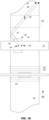
FIG. 1B depicts the operations of stationery thermographic camera(s) 22 which measures the radiant infrared energy emitted bycoated sheet 42 across the entire width of the coated sheet, that is, from edge to edge along the cross direction. Thethermographic camera 22 generates a series of thermographic images which can be superimposed to form a continuous thermographic image of the entirecoated sheet 42. Linear tracks 50 and 52 depict two successive elongated sections or regions of thecoated sheet 42 where thermographic data is photographed bythermographic camera 22. - Positioned downstream at a specific distance from the
camera 22 is scanningdevice 24 that includes a beta gauge which measures the basis weight and/or thickness of thecoated sheet 42. The scanning device periodically traversescoated sheet 42 generally at a constant speed. The beta gauge is shown measuring spot orarea 54 of thecoated sheet 42. The beta gauge does not measure the selected sheet property at locations which are aligned exactly perpendicular to the longitudinal edges of the sheet. Instead, because of the sheet velocity, the scanning device travel diagonally across the coated sheet surface, with the result that consecutive scanning paths have a zig-zag pattern with respect to the direction perpendicular to the longitudinal edges ofcoated sheet 42. - An example of such as zig-zag pattern are scanning
paths scanning device 24 traverses the surface of sheet during back-and-forth consecutive scans. The angles of each of the scanning paths relative to the true cross-direction depend upon the cross-directional velocity of the scanning device and upon the machine-directional velocity of thecoated sheet 42 which is known. The zig-zag pattern covers a relatively small portion of thecoated sheet 42 surface. - In addition to the beta gauge,
scanning device 24 also houses an infrared temperature sensor that measures the temperature spot orarea 55 of thecoated sheet 42. That is, as the scanning device traverses back-and-forth over the movingcoated sheet 42, the beta gauge and IR temperaturesensor monitor locations spot 55 and laterally offset in the CD fromspot 54. Thus,spot 55 defines zig-zagpattern scanning paths scanning device 24 traverses the surface of sheet during back-and-forth consecutive scans. The zig-zag patterns spots coated sheet 42. -
Region 60 represents a part on thecoated sheet 42 that has moved passed thescanning device 24. Since the speed of thecoated sheet 42 moving in the machine direction is controlled and the distance betweenframe 14 andframe 16 is fixed, the time required for thecoated sheet 42 travel fromthermographic camera 22 andscanning device 24 can be computed. Thus, withinregion 60 alongscanning patterns scanning device 24 has monitored (i) the basis weight and/or thickness with the beta gauge and (ii) the surface temperature with the IR temperature sensor. This information is used with the thermographic image data ofregion 60 to derived the basis weight and/or thickness distribution of the region. - The scanning device 24 (
Fig. 1B ) includes scanning heads 70, 72 which enclose orhouse radiation source 74 andradiation detector 76, respectively, as shown inFIG. 2 . Theradiation source 74 emitsradiation 80 that is directed toward anarea 54 on thecoated sheet 42 which is moving in the machine direction. The intensity of theradiation 82 which is transmitted through the coated sheet is sensed byradiation detector 76. The detector senses the amount of radiation absorbed by the coated sheet which gives a direct indication of the basis weight of the material.Radiation source 74 preferably emits beta radiation for the measurement of basis weight or thickness.Scanner head 70 also houses aninfrared sensor 78 with a spot size which is preferably smaller than 6 mm and response time of less than 100 msec and with a data rate exceeding 1 kHz in order to provide a sheet temperature profile with adequate resolution in the CD. As shown inFIG. 1B , the area where sheet temperature is measured by IR sensor 78 (FIG. 2 ) will be offset in the plus (+) or minus (-) MD direction depending on the CD direction of scan. - Beta gauges are nuclear measuring devices which emit beta rays. Typically, a single-layer composition, such as single-layer metal foil or electrode layer, has a known beta ray absorption coefficient and a known density. Using a beta gauge, the mass per unit area of the single-layer foil for instance, can be determined. That is, by multiplying the raw output of the beta gauge by the known adsorption coefficient, the mass per unit area can be calculated for each point on the foil to be measured. Similarly, the thickness at each such point corresponds to the mass per unit area divided by the known density. However, when using a beta gauge to measure mass and thickness of multilayer films or composite sheets such as coated metal substrates, the adsorption coefficient and density of each layer as well as the fractional composition of each layer must be considered in deriving a nominal composite adsorption coefficient for the multilayer film or composite sheet.
- As illustrated in
FIG. 3 , the operative faces of the dual scanner heads 70, 72 define a measurement gap that accommodatescoated sheet 42 which moves in the MD. The cross directional movement of the dual scanner heads is synchronized with respect to speed and direction so that they are aligned with each other. Because thecoated sheet 42 is traveling in the MD, which is perpendicular to the cross direction, the measurements made by dual head scanner heads cover only a small area along the length of thecoated sheet 42. - During operation of the coating process shown in
FIGS. 1A and1B , as thecoated sheet 42 exitsdryer 18 thermographic images ofcoated sheet 42 are continuously captured bycamera 22. For example, thermographic image data forsuccessive sections coated sheet 42 is recorded.FIG. 4 is a representative surface temperature profile forsection 50 that is derived from the thermographic image data. The graph depicts the surface temperature from one edge of thecoated sheet 42 to the other edge along the cross direction. The CD distance from edge to edge is arbitrarily designated from 0 to 100. When thesame section 50 passes by scanningdevice 24, the beta gauge measures the basis weight and/or thickness and the IR temperature sensor measures the surface temperature at adjacent or co-located positions of thecoated sheet 42 along a zig-zag pattern. -
FIG. 5 is a representative surface temperature profile of the same cross section of section 50 (FIG. 1B ) of the coated sheet that is depicted inFIG. 4 . The graph inFIG. 5 is derived by using the surface temperature that is measured at a specific location along the cross direction by the IR temperature sensor inscanning device 24 and calculating the temperature difference between the two surface temperatures. For example, if the downstream IR temperatures sensor measures the coated sheet at the midpoint along the cross direction, then that temperature is compared to the temperature at the midpoint shown inFIG. 4 which will be at a higher temperature. The graph inFIG. 5 has the same general profile as the graph inFIG. 4 except that the temperature in the former graph is lowered by the temperature differential as measured at the midpoint.FIGS. 4 and 5 also show edge effects in that the temperature at each end of moving sheet is lower due to the higher cooling rates at the outer borders of the sheet. -
FIG. 6 is a representative basis weight profile which is derived from the beta gauge measurement and applying the measurement to scaleFIG. 5 . In other words, the basis weight profile has the same general profile as the temperature graph shown inFIG. 6 but the beta gauge measurement of the single spot along the cross direction is used to scale the rest of the profile. In addition, the edge effects have been accounted for to yield a more accurate basis weight profile. A method of quantifying the cooling effects at the edges is to perform simulations using coated sheets or standards made of substrates of known thicknesses and applying coatings of known thicknesses thereon. These standards are heated in a dryer and subsequently undergo thermographic imaging, IR detection and beta gauge measurement. The standards are tested under different conditions including, for instance, dryer temperature, ambient temperature, speed of the moving sheet, distance between the IR thermographic camera and the downstream scanning device and other operating conditions. The cross directional temperature profiles generated using these standards permit analysis of the effects of edge cooling under different operating conditions. Mathematical relationships can be developed that models the effects of edge cooling. Alternatively, a library consisting of experimental results using different standards operating under various conditions can be used to formulate as calibration curves or a look-up table. In either case, when a basis weight cross directional profile is generated from a cross directional temperature profile, the edge effects can be compensated for to produce a more accurate basis weight profile. As shown inFIG. 6 , the basis weight cross directional profile shows more uniformity when the edge effects are accounted for. -
FIG. 7 depicts a process for controlling the manufacture of electrodes by continuously measuring the basis weight (or thickness) and corresponding temperature profiles from the scanning device (after the end of every scan) and the temperature profiles from the thermographic camera (e.g., every second). Digitized signals are fed to acomputer 102.Memory 104 includes a library of calibration curves or look-up tables that is used to compensate for edge cooling effects in calculating the basis weight or thickness. -
Controller 100 includes any hardware, software, firmware or combination thereof for performing the measurements in coating process shown inFIGS. 1A and1B .Controller 100 could, for instance, include amicroprocessor 102 andmemory 104 storing instructions and data used, generated, and collected by the processor. Thecontroller 100 regulates thecoaters 6, 14 (FIG. 1A ) in response to the CD basis weights in order to achieve the desired specifications. - While the invention has been illustrated in measuring characteristics of coated metal sheets, it is understood that the invention can be monitored moving sheets in general which include, but are not limited, to paper and plastic webs or sheets. In the case the sheet does not include a metal substrate, instead of using a nuclear gauge, the basis weight or thickness can be measured by a scanning infrared radiation sensor.
- The foregoing has described the principles, preferred embodiments and modes of operation of the present invention. However, the invention should not be construed as being limited to the particular embodiments discussed. Thus, the above-described embodiments should be regarded as illustrative rather than restrictive, and it should be appreciated that variations may be made in those embodiments by workers skilled in the art without departing from the scope of the present invention as defined by the following claims.
Claims (7)
- A system of monitoring the formation of a traveling sheet of material, that moves in a machine direction (MD), which comprises:a thermal imaging device (22) that is configured to capture a thermal image of the sheet material (42) along a cross direction at a first position along the MD to generate sequential temperature profiles of the traveling sheet of material;characterized bymeans for measuring an areal weight (74,76) of the traveling sheet of material at a second position along the MD that is downstream of the first position;a temperature sensor (78) that is configured to measure the temperature of the sheet of material at a third position, wherein the third position is adjacent to the second position along the MD; anda controller (100) that is configured to compute the areal weight of the traveling sheet of material along the cross direction (CD), the controller is configured to use the sequential temperature profiles, the means for measuring the areal weight, and the temperature sensor for computing the areal weight in the CD.
- The system of claim 1 wherein the controller (100) is configured to use the areal weight and corresponding temperature measurement to correlate the sequential temperature profiles into cross directional areal weight distribution profiles of the traveling sheet of material.
- The system of claim 2 wherein the controller (100) is configured to compute the cross directional areal weight distribution profiles of the traveling sheet of material along substantially the entire width of the traveling sheet.
- The system of claim 1 wherein the means for measuring the areal weight (74, 76) of the traveling sheet comprises a scanner sensor (24) that traverses back and forth along the CD across the traveling sheet of material as the traveling sheet moves in the MD.
- The system of claim 4 wherein the scanner sensor (24) includes a radiation source (74) that directs radiation towards the traveling sheet of material and a radiation detector (76) that detects radiation that is transmitted through the traveling sheet of material.
- A method of calculating the weight per unit area of a composite coated sheet, which is moving in a machine direction (MD), that comprises:(a) generating thermal image data of the composite coated sheet along a cross direction (CD) at a first position along the MD;
characterized by(b) measuring the weight per unit area of the composite coated sheet of an interrogation spot located at a second position along the MD, which is downstream from the first position;(c) measuring the surface temperature of the composite coated sheet at or in the vicinity of the interrogation spot that is adjacent to the second position along the MD; and(d) computing the weight per unit area of the composite coated sheet along a CD of the composite coated sheet using the thermal image data, weight per unit area of the composite coated sheet of the interrogation spot, and the measure surface temperature. - The method of claim 6 wherein step (d) comprises compensating for higher cooling rates at edges of the composite coated sheet in computing the weight per unit area of the composite coated sheet along the CD.
Applications Claiming Priority (1)
| Application Number | Priority Date | Filing Date | Title |
|---|---|---|---|
| US17/216,567 US11826773B2 (en) | 2021-03-29 | 2021-03-29 | Correlate thermographic image data to online scanning basis weight measurement |
Publications (2)
| Publication Number | Publication Date |
|---|---|
| EP4067885A1 EP4067885A1 (en) | 2022-10-05 |
| EP4067885B1 true EP4067885B1 (en) | 2023-10-04 |
Family
ID=80739042
Family Applications (1)
| Application Number | Title | Priority Date | Filing Date |
|---|---|---|---|
| EP22161422.5A Active EP4067885B1 (en) | 2021-03-29 | 2022-03-10 | Correlate thermographic image data to online scanning basis weight measurement |
Country Status (5)
| Country | Link |
|---|---|
| US (2) | US11826773B2 (en) |
| EP (1) | EP4067885B1 (en) |
| JP (1) | JP7247395B2 (en) |
| KR (1) | KR102752981B1 (en) |
| CA (1) | CA3152880C (en) |
Families Citing this family (8)
| Publication number | Priority date | Publication date | Assignee | Title |
|---|---|---|---|---|
| WO2024075575A1 (en) * | 2022-10-03 | 2024-04-11 | 富士フイルム株式会社 | Method for manufacturing electrode layer |
| FR3125596B1 (en) * | 2022-11-07 | 2025-01-10 | Verkor | Electrode defect detection method and system |
| US12372476B2 (en) * | 2022-11-11 | 2025-07-29 | Honeywell International Inc. | Compact-cross direction C-frame scanner |
| US20240240864A1 (en) * | 2023-01-13 | 2024-07-18 | Quantum IR Technologies, LLC | Rotary kiln interior coating analytics and monitoring systems |
| US12529660B2 (en) | 2023-05-08 | 2026-01-20 | Honeywell International Inc. | Integrated quality monitoring view for battery manufacturing process |
| US12601590B2 (en) * | 2023-06-21 | 2026-04-14 | Honeywell International Inc. | Method to control gap for sheet manufacturing measurement processes |
| EP4722644A1 (en) * | 2024-10-02 | 2026-04-08 | LG Energy Solution, Ltd. | An apparatus for inspecting a coated electrode sheet for a secondary battery and a method using the same |
| CN118988640B (en) * | 2024-10-26 | 2025-01-24 | 山东华盛创新纺织科技有限公司 | A temperature measuring device and method for detecting thermosensitive color-changing textiles |
Family Cites Families (20)
| Publication number | Priority date | Publication date | Assignee | Title |
|---|---|---|---|---|
| US3681595A (en) | 1970-04-03 | 1972-08-01 | Measurex Corp | Basis weight gauge standardizing system |
| JPS6161004A (en) * | 1984-08-31 | 1986-03-28 | Rheon Autom Mach Co Ltd | Continuous measuring method of continuous body |
| US4921574A (en) | 1989-01-27 | 1990-05-01 | Measurex Corporation | Process for controlling properties of travelling sheets with scan widths less than the sheet width |
| US4943721A (en) | 1989-06-22 | 1990-07-24 | Measurex Corporation | Method of obtaining accurate compositional information of multi-layer compositions |
| US5099118A (en) * | 1991-05-30 | 1992-03-24 | Francis Kenneth E | Dual sensor scanner for measuring weight of paper and related sheet products |
| US5795394A (en) | 1997-06-02 | 1998-08-18 | Honeywell-Measurex | Coating weight measuring and control apparatus |
| CA2295543A1 (en) | 1997-07-07 | 1999-01-21 | Siemens Aktiengesellschaft | Method and device for determining the thickness of paper or cardboard by measuring on a continuous material web |
| FI112881B (en) * | 1999-12-09 | 2004-01-30 | Metso Paper Inc | Method and apparatus for determining the profile of a coating layer |
| EP2090674B1 (en) | 2008-01-25 | 2013-03-13 | Applied Materials, Inc. | Vacuum coating installation and method of producing a coating layer on a substrate. |
| JP2010032387A (en) | 2008-07-29 | 2010-02-12 | Yamabun Denki:Kk | Temperature measuring method, temperature measuring apparatus, temperature control method, temperature control apparatus, correction method, and correction apparatus |
| US8596861B2 (en) | 2008-11-06 | 2013-12-03 | Honeywell International Inc | Method and system for detecting corrosion under insulation |
| US8394449B2 (en) * | 2008-12-19 | 2013-03-12 | Honeywell Asca Inc. | Differential coat weight measurement by means of nuclear or X-ray gauges |
| JP5522025B2 (en) | 2010-12-27 | 2014-06-18 | トヨタ自動車株式会社 | Coating device, coating method, battery manufacturing method |
| KR101290424B1 (en) * | 2012-03-29 | 2013-08-07 | 현대제철 주식회사 | Apparatus for measuring warp and camber of rolled material using thermal image and controlling method therefor |
| JP6031857B2 (en) | 2012-07-11 | 2016-11-24 | 横河電機株式会社 | Radiation measurement method |
| JP2014025709A (en) | 2012-07-24 | 2014-02-06 | Yokogawa Electric Corp | Radiation measurement method and radiation measurement device |
| JP2014032767A (en) | 2012-08-01 | 2014-02-20 | Toyota Motor Corp | Method and device for manufacturing electrode for battery |
| US10041673B2 (en) | 2013-07-25 | 2018-08-07 | Honeywell International Inc. | Flare stack monitoring |
| EP3805733B1 (en) * | 2018-05-31 | 2023-10-25 | PSM International, Inc. | Quality measuring method and quality measuring device for long sheet material |
| US11879765B2 (en) | 2018-09-26 | 2024-01-23 | Honeywell International Inc. | Apparatus for composite sheet weight determinations |
-
2021
- 2021-03-29 US US17/216,567 patent/US11826773B2/en active Active
-
2022
- 2022-03-10 EP EP22161422.5A patent/EP4067885B1/en active Active
- 2022-03-17 JP JP2022042512A patent/JP7247395B2/en active Active
- 2022-03-21 CA CA3152880A patent/CA3152880C/en active Active
- 2022-03-23 KR KR1020220035990A patent/KR102752981B1/en active Active
-
2023
- 2023-10-24 US US18/383,451 patent/US20240058833A1/en active Pending
Also Published As
| Publication number | Publication date |
|---|---|
| US20240058833A1 (en) | 2024-02-22 |
| CA3152880C (en) | 2025-09-23 |
| EP4067885A1 (en) | 2022-10-05 |
| CA3152880A1 (en) | 2022-09-29 |
| US11826773B2 (en) | 2023-11-28 |
| KR102752981B1 (en) | 2025-01-09 |
| KR20220135183A (en) | 2022-10-06 |
| JP2022153299A (en) | 2022-10-12 |
| US20220305516A1 (en) | 2022-09-29 |
| JP7247395B2 (en) | 2023-03-28 |
Similar Documents
| Publication | Publication Date | Title |
|---|---|---|
| EP4067885B1 (en) | Correlate thermographic image data to online scanning basis weight measurement | |
| JP7684998B2 (en) | Improved traceability of battery electrodes with fiducial markers - Patents.com | |
| CN102449429B (en) | Method and apparatus for measuring coating thickness of wet paint | |
| CN115839902B (en) | Areal density measurement methods, areal density measurement systems and computer equipment | |
| US6567720B1 (en) | Method and apparatus for time synchronized measurement correction of multidimensional periodic effects on a moving web | |
| EP4354114B1 (en) | Surface density measurement method, surface density measurement system and computer device | |
| CA2426188C (en) | Process and device for measuring distances on bright metal strips | |
| CN121089637A (en) | Coating equipment and pole piece coating thickness detection method | |
| JP7702447B2 (en) | Machine direction position profile measurement in sheet manufacturing systems | |
| KR20230119176A (en) | Web edge instrumentation | |
| CN121263652A (en) | Device and method for determining the thickness of a paint layer on an electrical sheet | |
| US6749888B2 (en) | Method and apparatus for determining the profile of a coating layer | |
| CN119044110A (en) | Dryness model construction method, dryness detection method and dryness detection system | |
| KR20240162561A (en) | Substrate alloy influence compensation | |
| WO2024008720A1 (en) | Measurement system and method for measuring a coated electrode | |
| CN118489057B (en) | Method and apparatus for basis weight measurement of sheet or foil incorporating an X-ray sensor and an ultrasonic sensor | |
| CN121540254A (en) | Electrode coating weight testing methods, systems, equipment and storage media | |
| JPH08304036A (en) | Method and apparatus for inspecting coating unevenness | |
| US20250020502A1 (en) | Roll Weight System for On Machine Dynamic Verification | |
| CN121557874A (en) | Pole piece detecting system | |
| JPS61129067A (en) | Method for controlling coating thickness of rubber coating calender | |
| JPH01173810A (en) | Method for measuring coating film thickness | |
| JPH04148851A (en) | Method for measuring gloss irregularity in band shape on surface of rolled plate material |
Legal Events
| Date | Code | Title | Description |
|---|---|---|---|
| PUAI | Public reference made under article 153(3) epc to a published international application that has entered the european phase |
Free format text: ORIGINAL CODE: 0009012 |
|
| STAA | Information on the status of an ep patent application or granted ep patent |
Free format text: STATUS: REQUEST FOR EXAMINATION WAS MADE |
|
| 17P | Request for examination filed |
Effective date: 20220310 |
|
| AK | Designated contracting states |
Kind code of ref document: A1 Designated state(s): AL AT BE BG CH CY CZ DE DK EE ES FI FR GB GR HR HU IE IS IT LI LT LU LV MC MK MT NL NO PL PT RO RS SE SI SK SM TR |
|
| GRAP | Despatch of communication of intention to grant a patent |
Free format text: ORIGINAL CODE: EPIDOSNIGR1 |
|
| STAA | Information on the status of an ep patent application or granted ep patent |
Free format text: STATUS: GRANT OF PATENT IS INTENDED |
|
| RIC1 | Information provided on ipc code assigned before grant |
Ipc: H01M 4/88 20060101ALI20230424BHEP Ipc: G01G 17/02 20060101ALI20230424BHEP Ipc: G01G 9/00 20060101ALI20230424BHEP Ipc: G01N 25/72 20060101ALI20230424BHEP Ipc: G01N 23/16 20180101AFI20230424BHEP |
|
| P01 | Opt-out of the competence of the unified patent court (upc) registered |
Effective date: 20230414 |
|
| INTG | Intention to grant announced |
Effective date: 20230526 |
|
| RIN1 | Information on inventor provided before grant (corrected) |
Inventor name: LEE, HYUONGSUN |
|
| GRAS | Grant fee paid |
Free format text: ORIGINAL CODE: EPIDOSNIGR3 |
|
| GRAA | (expected) grant |
Free format text: ORIGINAL CODE: 0009210 |
|
| STAA | Information on the status of an ep patent application or granted ep patent |
Free format text: STATUS: THE PATENT HAS BEEN GRANTED |
|
| AK | Designated contracting states |
Kind code of ref document: B1 Designated state(s): AL AT BE BG CH CY CZ DE DK EE ES FI FR GB GR HR HU IE IS IT LI LT LU LV MC MK MT NL NO PL PT RO RS SE SI SK SM TR |
|
| REG | Reference to a national code |
Ref country code: GB Ref legal event code: FG4D |
|
| REG | Reference to a national code |
Ref country code: CH Ref legal event code: EP |
|
| REG | Reference to a national code |
Ref country code: DE Ref legal event code: R096 Ref document number: 602022000600 Country of ref document: DE |
|
| REG | Reference to a national code |
Ref country code: IE Ref legal event code: FG4D |
|
| REG | Reference to a national code |
Ref country code: LT Ref legal event code: MG9D |
|
| REG | Reference to a national code |
Ref country code: NL Ref legal event code: MP Effective date: 20231004 |
|
| REG | Reference to a national code |
Ref country code: AT Ref legal event code: MK05 Ref document number: 1618214 Country of ref document: AT Kind code of ref document: T Effective date: 20231004 |
|
| PG25 | Lapsed in a contracting state [announced via postgrant information from national office to epo] |
Ref country code: NL Free format text: LAPSE BECAUSE OF FAILURE TO SUBMIT A TRANSLATION OF THE DESCRIPTION OR TO PAY THE FEE WITHIN THE PRESCRIBED TIME-LIMIT Effective date: 20231004 |
|
| PG25 | Lapsed in a contracting state [announced via postgrant information from national office to epo] |
Ref country code: GR Free format text: LAPSE BECAUSE OF FAILURE TO SUBMIT A TRANSLATION OF THE DESCRIPTION OR TO PAY THE FEE WITHIN THE PRESCRIBED TIME-LIMIT Effective date: 20240105 |
|
| PG25 | Lapsed in a contracting state [announced via postgrant information from national office to epo] |
Ref country code: IS Free format text: LAPSE BECAUSE OF FAILURE TO SUBMIT A TRANSLATION OF THE DESCRIPTION OR TO PAY THE FEE WITHIN THE PRESCRIBED TIME-LIMIT Effective date: 20240204 |
|
| PG25 | Lapsed in a contracting state [announced via postgrant information from national office to epo] |
Ref country code: LT Free format text: LAPSE BECAUSE OF FAILURE TO SUBMIT A TRANSLATION OF THE DESCRIPTION OR TO PAY THE FEE WITHIN THE PRESCRIBED TIME-LIMIT Effective date: 20231004 |
|
| PG25 | Lapsed in a contracting state [announced via postgrant information from national office to epo] |
Ref country code: AT Free format text: LAPSE BECAUSE OF FAILURE TO SUBMIT A TRANSLATION OF THE DESCRIPTION OR TO PAY THE FEE WITHIN THE PRESCRIBED TIME-LIMIT Effective date: 20231004 |
|
| PG25 | Lapsed in a contracting state [announced via postgrant information from national office to epo] |
Ref country code: ES Free format text: LAPSE BECAUSE OF FAILURE TO SUBMIT A TRANSLATION OF THE DESCRIPTION OR TO PAY THE FEE WITHIN THE PRESCRIBED TIME-LIMIT Effective date: 20231004 |
|
| PG25 | Lapsed in a contracting state [announced via postgrant information from national office to epo] |
Ref country code: LT Free format text: LAPSE BECAUSE OF FAILURE TO SUBMIT A TRANSLATION OF THE DESCRIPTION OR TO PAY THE FEE WITHIN THE PRESCRIBED TIME-LIMIT Effective date: 20231004 Ref country code: IS Free format text: LAPSE BECAUSE OF FAILURE TO SUBMIT A TRANSLATION OF THE DESCRIPTION OR TO PAY THE FEE WITHIN THE PRESCRIBED TIME-LIMIT Effective date: 20240204 Ref country code: GR Free format text: LAPSE BECAUSE OF FAILURE TO SUBMIT A TRANSLATION OF THE DESCRIPTION OR TO PAY THE FEE WITHIN THE PRESCRIBED TIME-LIMIT Effective date: 20240105 Ref country code: ES Free format text: LAPSE BECAUSE OF FAILURE TO SUBMIT A TRANSLATION OF THE DESCRIPTION OR TO PAY THE FEE WITHIN THE PRESCRIBED TIME-LIMIT Effective date: 20231004 Ref country code: BG Free format text: LAPSE BECAUSE OF FAILURE TO SUBMIT A TRANSLATION OF THE DESCRIPTION OR TO PAY THE FEE WITHIN THE PRESCRIBED TIME-LIMIT Effective date: 20240104 Ref country code: AT Free format text: LAPSE BECAUSE OF FAILURE TO SUBMIT A TRANSLATION OF THE DESCRIPTION OR TO PAY THE FEE WITHIN THE PRESCRIBED TIME-LIMIT Effective date: 20231004 Ref country code: PT Free format text: LAPSE BECAUSE OF FAILURE TO SUBMIT A TRANSLATION OF THE DESCRIPTION OR TO PAY THE FEE WITHIN THE PRESCRIBED TIME-LIMIT Effective date: 20240205 |
|
| PG25 | Lapsed in a contracting state [announced via postgrant information from national office to epo] |
Ref country code: SE Free format text: LAPSE BECAUSE OF FAILURE TO SUBMIT A TRANSLATION OF THE DESCRIPTION OR TO PAY THE FEE WITHIN THE PRESCRIBED TIME-LIMIT Effective date: 20231004 Ref country code: RS Free format text: LAPSE BECAUSE OF FAILURE TO SUBMIT A TRANSLATION OF THE DESCRIPTION OR TO PAY THE FEE WITHIN THE PRESCRIBED TIME-LIMIT Effective date: 20231004 Ref country code: PL Free format text: LAPSE BECAUSE OF FAILURE TO SUBMIT A TRANSLATION OF THE DESCRIPTION OR TO PAY THE FEE WITHIN THE PRESCRIBED TIME-LIMIT Effective date: 20231004 Ref country code: NO Free format text: LAPSE BECAUSE OF FAILURE TO SUBMIT A TRANSLATION OF THE DESCRIPTION OR TO PAY THE FEE WITHIN THE PRESCRIBED TIME-LIMIT Effective date: 20240104 Ref country code: LV Free format text: LAPSE BECAUSE OF FAILURE TO SUBMIT A TRANSLATION OF THE DESCRIPTION OR TO PAY THE FEE WITHIN THE PRESCRIBED TIME-LIMIT Effective date: 20231004 Ref country code: HR Free format text: LAPSE BECAUSE OF FAILURE TO SUBMIT A TRANSLATION OF THE DESCRIPTION OR TO PAY THE FEE WITHIN THE PRESCRIBED TIME-LIMIT Effective date: 20231004 |
|
| REG | Reference to a national code |
Ref country code: DE Ref legal event code: R097 Ref document number: 602022000600 Country of ref document: DE |
|
| PG25 | Lapsed in a contracting state [announced via postgrant information from national office to epo] |
Ref country code: DK Free format text: LAPSE BECAUSE OF FAILURE TO SUBMIT A TRANSLATION OF THE DESCRIPTION OR TO PAY THE FEE WITHIN THE PRESCRIBED TIME-LIMIT Effective date: 20231004 |
|
| PG25 | Lapsed in a contracting state [announced via postgrant information from national office to epo] |
Ref country code: CZ Free format text: LAPSE BECAUSE OF FAILURE TO SUBMIT A TRANSLATION OF THE DESCRIPTION OR TO PAY THE FEE WITHIN THE PRESCRIBED TIME-LIMIT Effective date: 20231004 |
|
| PG25 | Lapsed in a contracting state [announced via postgrant information from national office to epo] |
Ref country code: SK Free format text: LAPSE BECAUSE OF FAILURE TO SUBMIT A TRANSLATION OF THE DESCRIPTION OR TO PAY THE FEE WITHIN THE PRESCRIBED TIME-LIMIT Effective date: 20231004 |
|
| PG25 | Lapsed in a contracting state [announced via postgrant information from national office to epo] |
Ref country code: SM Free format text: LAPSE BECAUSE OF FAILURE TO SUBMIT A TRANSLATION OF THE DESCRIPTION OR TO PAY THE FEE WITHIN THE PRESCRIBED TIME-LIMIT Effective date: 20231004 Ref country code: SK Free format text: LAPSE BECAUSE OF FAILURE TO SUBMIT A TRANSLATION OF THE DESCRIPTION OR TO PAY THE FEE WITHIN THE PRESCRIBED TIME-LIMIT Effective date: 20231004 Ref country code: RO Free format text: LAPSE BECAUSE OF FAILURE TO SUBMIT A TRANSLATION OF THE DESCRIPTION OR TO PAY THE FEE WITHIN THE PRESCRIBED TIME-LIMIT Effective date: 20231004 Ref country code: IT Free format text: LAPSE BECAUSE OF FAILURE TO SUBMIT A TRANSLATION OF THE DESCRIPTION OR TO PAY THE FEE WITHIN THE PRESCRIBED TIME-LIMIT Effective date: 20231004 Ref country code: EE Free format text: LAPSE BECAUSE OF FAILURE TO SUBMIT A TRANSLATION OF THE DESCRIPTION OR TO PAY THE FEE WITHIN THE PRESCRIBED TIME-LIMIT Effective date: 20231004 Ref country code: DK Free format text: LAPSE BECAUSE OF FAILURE TO SUBMIT A TRANSLATION OF THE DESCRIPTION OR TO PAY THE FEE WITHIN THE PRESCRIBED TIME-LIMIT Effective date: 20231004 Ref country code: CZ Free format text: LAPSE BECAUSE OF FAILURE TO SUBMIT A TRANSLATION OF THE DESCRIPTION OR TO PAY THE FEE WITHIN THE PRESCRIBED TIME-LIMIT Effective date: 20231004 |
|
| PLBE | No opposition filed within time limit |
Free format text: ORIGINAL CODE: 0009261 |
|
| STAA | Information on the status of an ep patent application or granted ep patent |
Free format text: STATUS: NO OPPOSITION FILED WITHIN TIME LIMIT |
|
| 26N | No opposition filed |
Effective date: 20240705 |
|
| PG25 | Lapsed in a contracting state [announced via postgrant information from national office to epo] |
Ref country code: SI Free format text: LAPSE BECAUSE OF FAILURE TO SUBMIT A TRANSLATION OF THE DESCRIPTION OR TO PAY THE FEE WITHIN THE PRESCRIBED TIME-LIMIT Effective date: 20231004 |
|
| PG25 | Lapsed in a contracting state [announced via postgrant information from national office to epo] |
Ref country code: SI Free format text: LAPSE BECAUSE OF FAILURE TO SUBMIT A TRANSLATION OF THE DESCRIPTION OR TO PAY THE FEE WITHIN THE PRESCRIBED TIME-LIMIT Effective date: 20231004 |
|
| PG25 | Lapsed in a contracting state [announced via postgrant information from national office to epo] |
Ref country code: LU Free format text: LAPSE BECAUSE OF NON-PAYMENT OF DUE FEES Effective date: 20240310 |
|
| PG25 | Lapsed in a contracting state [announced via postgrant information from national office to epo] |
Ref country code: MC Free format text: LAPSE BECAUSE OF FAILURE TO SUBMIT A TRANSLATION OF THE DESCRIPTION OR TO PAY THE FEE WITHIN THE PRESCRIBED TIME-LIMIT Effective date: 20231004 |
|
| PG25 | Lapsed in a contracting state [announced via postgrant information from national office to epo] |
Ref country code: MC Free format text: LAPSE BECAUSE OF FAILURE TO SUBMIT A TRANSLATION OF THE DESCRIPTION OR TO PAY THE FEE WITHIN THE PRESCRIBED TIME-LIMIT Effective date: 20231004 Ref country code: LU Free format text: LAPSE BECAUSE OF NON-PAYMENT OF DUE FEES Effective date: 20240310 |
|
| REG | Reference to a national code |
Ref country code: BE Ref legal event code: MM Effective date: 20240331 |
|
| PG25 | Lapsed in a contracting state [announced via postgrant information from national office to epo] |
Ref country code: BE Free format text: LAPSE BECAUSE OF NON-PAYMENT OF DUE FEES Effective date: 20240331 |
|
| PG25 | Lapsed in a contracting state [announced via postgrant information from national office to epo] |
Ref country code: FR Free format text: LAPSE BECAUSE OF NON-PAYMENT OF DUE FEES Effective date: 20240331 |
|
| PG25 | Lapsed in a contracting state [announced via postgrant information from national office to epo] |
Ref country code: IE Free format text: LAPSE BECAUSE OF NON-PAYMENT OF DUE FEES Effective date: 20240310 |
|
| PG25 | Lapsed in a contracting state [announced via postgrant information from national office to epo] |
Ref country code: IE Free format text: LAPSE BECAUSE OF NON-PAYMENT OF DUE FEES Effective date: 20240310 Ref country code: FR Free format text: LAPSE BECAUSE OF NON-PAYMENT OF DUE FEES Effective date: 20240331 Ref country code: BE Free format text: LAPSE BECAUSE OF NON-PAYMENT OF DUE FEES Effective date: 20240331 |
|
| PG25 | Lapsed in a contracting state [announced via postgrant information from national office to epo] |
Ref country code: CY Free format text: LAPSE BECAUSE OF FAILURE TO SUBMIT A TRANSLATION OF THE DESCRIPTION OR TO PAY THE FEE WITHIN THE PRESCRIBED TIME-LIMIT; INVALID AB INITIO Effective date: 20220310 |
|
| PG25 | Lapsed in a contracting state [announced via postgrant information from national office to epo] |
Ref country code: FI Free format text: LAPSE BECAUSE OF FAILURE TO SUBMIT A TRANSLATION OF THE DESCRIPTION OR TO PAY THE FEE WITHIN THE PRESCRIBED TIME-LIMIT Effective date: 20231004 |
|
| REG | Reference to a national code |
Ref country code: CH Ref legal event code: H13 Free format text: ST27 STATUS EVENT CODE: U-0-0-H10-H13 (AS PROVIDED BY THE NATIONAL OFFICE) Effective date: 20251023 |
|
| PG25 | Lapsed in a contracting state [announced via postgrant information from national office to epo] |
Ref country code: TR Free format text: LAPSE BECAUSE OF FAILURE TO SUBMIT A TRANSLATION OF THE DESCRIPTION OR TO PAY THE FEE WITHIN THE PRESCRIBED TIME-LIMIT Effective date: 20231004 |
|
| PG25 | Lapsed in a contracting state [announced via postgrant information from national office to epo] |
Ref country code: CH Free format text: LAPSE BECAUSE OF NON-PAYMENT OF DUE FEES Effective date: 20250331 |
|
| PGFP | Annual fee paid to national office [announced via postgrant information from national office to epo] |
Ref country code: GB Payment date: 20260319 Year of fee payment: 5 |
|
| PGFP | Annual fee paid to national office [announced via postgrant information from national office to epo] |
Ref country code: DE Payment date: 20260320 Year of fee payment: 5 |