EP4067876A1 - Gas analyzer - Google Patents
Gas analyzer Download PDFInfo
- Publication number
- EP4067876A1 EP4067876A1 EP22164144.2A EP22164144A EP4067876A1 EP 4067876 A1 EP4067876 A1 EP 4067876A1 EP 22164144 A EP22164144 A EP 22164144A EP 4067876 A1 EP4067876 A1 EP 4067876A1
- Authority
- EP
- European Patent Office
- Prior art keywords
- gas analyzer
- axis
- light
- light emitting
- emitting element
- Prior art date
- Legal status (The legal status is an assumption and is not a legal conclusion. Google has not performed a legal analysis and makes no representation as to the accuracy of the status listed.)
- Granted
Links
Images


Classifications
-
- G—PHYSICS
- G01—MEASURING; TESTING
- G01N—INVESTIGATING OR ANALYSING MATERIALS BY DETERMINING THEIR CHEMICAL OR PHYSICAL PROPERTIES
- G01N21/00—Investigating or analysing materials by the use of optical means, i.e. using sub-millimetre waves, infrared, visible or ultraviolet light
- G01N21/17—Systems in which incident light is modified in accordance with the properties of the material investigated
- G01N21/25—Colour; Spectral properties, i.e. comparison of effect of material on the light at two or more different wavelengths or wavelength bands
- G01N21/31—Investigating relative effect of material at wavelengths characteristic of specific elements or molecules, e.g. atomic absorption spectrometry
- G01N21/39—Investigating relative effect of material at wavelengths characteristic of specific elements or molecules, e.g. atomic absorption spectrometry using tunable lasers
-
- G—PHYSICS
- G01—MEASURING; TESTING
- G01N—INVESTIGATING OR ANALYSING MATERIALS BY DETERMINING THEIR CHEMICAL OR PHYSICAL PROPERTIES
- G01N21/00—Investigating or analysing materials by the use of optical means, i.e. using sub-millimetre waves, infrared, visible or ultraviolet light
- G01N21/01—Arrangements or apparatus for facilitating the optical investigation
-
- G—PHYSICS
- G01—MEASURING; TESTING
- G01N—INVESTIGATING OR ANALYSING MATERIALS BY DETERMINING THEIR CHEMICAL OR PHYSICAL PROPERTIES
- G01N21/00—Investigating or analysing materials by the use of optical means, i.e. using sub-millimetre waves, infrared, visible or ultraviolet light
- G01N21/84—Systems specially adapted for particular applications
- G01N21/85—Investigating moving fluids or granular solids
-
- G—PHYSICS
- G01—MEASURING; TESTING
- G01N—INVESTIGATING OR ANALYSING MATERIALS BY DETERMINING THEIR CHEMICAL OR PHYSICAL PROPERTIES
- G01N33/00—Investigating or analysing materials by specific methods not covered by groups G01N1/00 - G01N31/00
- G01N33/0004—Gaseous mixtures, e.g. polluted air
- G01N33/0009—General constructional details of gas analysers, e.g. portable test equipment
- G01N33/0027—General constructional details of gas analysers, e.g. portable test equipment concerning the detector
-
- G—PHYSICS
- G01—MEASURING; TESTING
- G01N—INVESTIGATING OR ANALYSING MATERIALS BY DETERMINING THEIR CHEMICAL OR PHYSICAL PROPERTIES
- G01N21/00—Investigating or analysing materials by the use of optical means, i.e. using sub-millimetre waves, infrared, visible or ultraviolet light
- G01N21/01—Arrangements or apparatus for facilitating the optical investigation
- G01N2021/0106—General arrangement of respective parts
-
- G—PHYSICS
- G01—MEASURING; TESTING
- G01N—INVESTIGATING OR ANALYSING MATERIALS BY DETERMINING THEIR CHEMICAL OR PHYSICAL PROPERTIES
- G01N21/00—Investigating or analysing materials by the use of optical means, i.e. using sub-millimetre waves, infrared, visible or ultraviolet light
- G01N21/01—Arrangements or apparatus for facilitating the optical investigation
- G01N21/03—Cuvette constructions
- G01N21/031—Multipass arrangements
- G01N2021/0314—Double pass, autocollimated path
-
- G—PHYSICS
- G01—MEASURING; TESTING
- G01N—INVESTIGATING OR ANALYSING MATERIALS BY DETERMINING THEIR CHEMICAL OR PHYSICAL PROPERTIES
- G01N21/00—Investigating or analysing materials by the use of optical means, i.e. using sub-millimetre waves, infrared, visible or ultraviolet light
- G01N21/17—Systems in which incident light is modified in accordance with the properties of the material investigated
- G01N21/25—Colour; Spectral properties, i.e. comparison of effect of material on the light at two or more different wavelengths or wavelength bands
- G01N21/31—Investigating relative effect of material at wavelengths characteristic of specific elements or molecules, e.g. atomic absorption spectrometry
- G01N21/39—Investigating relative effect of material at wavelengths characteristic of specific elements or molecules, e.g. atomic absorption spectrometry using tunable lasers
- G01N2021/396—Type of laser source
- G01N2021/399—Diode laser
-
- G—PHYSICS
- G01—MEASURING; TESTING
- G01N—INVESTIGATING OR ANALYSING MATERIALS BY DETERMINING THEIR CHEMICAL OR PHYSICAL PROPERTIES
- G01N21/00—Investigating or analysing materials by the use of optical means, i.e. using sub-millimetre waves, infrared, visible or ultraviolet light
- G01N21/84—Systems specially adapted for particular applications
- G01N21/85—Investigating moving fluids or granular solids
- G01N2021/8578—Gaseous flow
-
- G—PHYSICS
- G01—MEASURING; TESTING
- G01N—INVESTIGATING OR ANALYSING MATERIALS BY DETERMINING THEIR CHEMICAL OR PHYSICAL PROPERTIES
- G01N2201/00—Features of devices classified in G01N21/00
- G01N2201/06—Illumination; Optics
- G01N2201/061—Sources
- G01N2201/06113—Coherent sources; lasers
-
- G—PHYSICS
- G01—MEASURING; TESTING
- G01N—INVESTIGATING OR ANALYSING MATERIALS BY DETERMINING THEIR CHEMICAL OR PHYSICAL PROPERTIES
- G01N2201/00—Features of devices classified in G01N21/00
- G01N2201/06—Illumination; Optics
- G01N2201/063—Illuminating optical parts
- G01N2201/0636—Reflectors
Definitions
- the present disclosure relates to a gas analyzer.
- a holding member that holds a light emitting element is adjustable in position along at least one axis that is not parallel to the optical axis of the light emitting element.
- PTL patent literature
- the aforementioned conventional gas analyzer has room for improvement in terms of easily facilitating the alignment of the position and angle of the optical axis of the light emitting element so that the light irradiated from the light emitting element can be received by a light receiving element.
- a gas analyzer is a gas analyzer for measuring a predetermined component in a measurement gas by irradiating light on the measurement gas from a light emitting element and receiving light that passes through the measurement gas, the gas analyzer including a base member configured to be adjustable in position along at least one axis that is not parallel to an optical axis of the light emitting element; and a holding member configured to hold the light emitting element and to be held to the base member in an angularly adjustable manner around at least one axis that is not parallel to the optical axis. According to this configuration, alignment can easily be facilitated.
- a gas analyzer further includes a plurality of light emitters that each include the base member, the holding member, and the light emitting element. According to this configuration, a plurality of predetermined components in the measurement gas can be measured using the plurality of light emitters. Furthermore, the plurality of light emitters can be aligned independently from each other, thereby achieving easy alignment.
- a gas analyzer further includes a reflector configured to reflect the light irradiated by the light emitting element so that the light travels back and forth in the measurement gas. According to this configuration, the optical path length in the measurement gas can be doubled by the reflector, thereby increasing the measurement accuracy.
- a light emitter and a reflector are separately mounted on a channel wall forming a channel for the measurement gas, the light emitter including the base member, the holding member, and the light emitting element, and the reflector being configured to reflect the light irradiated by the light emitting element so that the light travels back and forth in the measurement gas.
- the holding member is held to the base member in an angularly adjustable manner around at least two axes that are not parallel to the optical axis. According to this configuration, alignment can more easily be facilitated.
- the base member is adjustable in position along at least two axes that are not parallel to the optical axis. According to this configuration, alignment can more easily be facilitated.
- the gas analyzer uses tunable diode laser absorption spectroscopy. According to this configuration, predetermined components in the measurement gas can be measured accurately.
- the holding member is held to the base member in an angularly adjustable manner around at least one axis that intersects the optical axis. According to this configuration, alignment can more easily be facilitated.
- the holding member is held to the base member in an angularly adjustable manner around at least two axes that each intersect the optical axis and intersect each other. According to this configuration, alignment can more easily be facilitated.
- the base member is adjustable in position along at least one axis that intersects the optical axis. According to this configuration, alignment can more easily be facilitated.
- the base member is adjustable in position along at least two axes that each intersect the optical axis and intersect each other. According to this configuration, alignment can more easily be facilitated.
- a gas analyzer that easily facilitates alignment can be provided.
- a gas analyzer 1 uses Tunable Diode Laser Absorption Spectroscopy (TDLAS), for example, to measure a plurality of predetermined components in a measurement gas 3 by irradiating light 4 from a plurality of light emitting elements 2 on the measurement gas 3 and receiving the light 4 that passes through the measurement gas 3.
- TDLAS Tunable Diode Laser Absorption Spectroscopy
- Tunable Diode Laser Absorption Spectroscopy is a method of measuring the concentration, for example, of a predetermined component in a measurement gas 3 based on the optical path length in the measurement gas 3 and the intensity difference, i.e., the absorbance, of a specific wavelength component of the light 4 before and after the light 4 passes through the measurement gas 3.
- the predetermined component include CO, CO 2 , H 2 O, C n H m , NH 3 , and O 2 .
- the gas analyzer 1 includes a plurality of light transmitters/receivers 6, each including a light emitting element 2, such as a laser diode, and a light receiving element 5, such as a photodiode, that receives light 4 irradiated from the light emitting element 2.
- the gas analyzer 1 also includes a reflector 7 that reflects the light 4 irradiated by the plurality of light emitting elements 2 so that the light 4 travels back and forth in the measurement gas 3.
- a plurality of predetermined components in the measurement gas 3 can be measured.
- the number of light transmitters/receivers 6 is two in the present embodiment, but this example is not limiting, and the number can be increased or decreased as appropriate.
- Each light transmitter/receiver 6 is housed in a first housing 8.
- the first housing 8 is mounted, via an alignment flange 10, on a cylindrical channel wall 9 that forms a channel for the measurement gas 3.
- the first housing 8 is angularly adjustable with respect to the channel wall 9 by adjustment of the alignment flange 10 (see the bold arrow in FIG. 1 ). By angular adjustment of the alignment flange 10, the optical axes of the plurality of light emitting elements 2 can be angularly adjusted together.
- the reflector 7 is formed by an optical element such as a retroreflector that reflects the light 4.
- the reflector 7 is housed in a second housing 11 in an angularly adjustable manner.
- the second housing 11 is mounted on the channel wall 9 separately from the first housing 8.
- the optical path length in the measurement gas 3 can be doubled by the reflector 7, thereby increasing the measurement accuracy.
- the gas analyzer 1 is an opposing type that includes two mounting portions (the first housing 8 and the second housing 11) that face each other across a channel.
- the gas analyzer 1 is also a reflecting type that includes the reflector 7 and is a multiple optical axis type that includes the plurality of light emitting elements 2.
- Opposing types, reflecting types and multiple optical axis types tend to have a higher degree of difficulty in alignment, and the gas analyzer 1 according to the present embodiment, which falls under all of these types, tends to have a particularly high degree of difficulty in alignment.
- the gas analyzer 1 is configured so that the positions and angles (directions) of the plurality of optical axes can be adjusted independently of each other to facilitate alignment. More specifically, the gas analyzer 1 includes a plurality of light emitters 14 that each include a base member 12, a holding member 13, and the light emitting element 2. Since the light emitters 14 have similar configurations, one light emitter 14 is illustrated in detail below.
- the holding member 13 holds the light emitting element 2.
- the light emitting element 2 emits light 4 along an optical axis.
- the axis coinciding with the optical axis is referred to below as the Z-axis.
- the holding member 13 has an annular shape centered on the Z-axis and integrally holds the light emitting element 2 at the inner circumferential edge of the holding member 13.
- the holding member 13 has a contact surface 13a that is annular, centered on the Z-axis, and that forms a shape along a spherical surface having a spherical center O on the Z-axis.
- the base member 12 has an annular shape centered on the Z-axis when the holding member 13 is in the neutral position illustrated in FIG. 2B .
- the neutral position refers to a position at which the Z-axis is perpendicular to both the below-described X-direction and the below-described Y-direction.
- the base member 12 includes a receptive member 12b, which has a contacted surface 12a contacted by the contact surface 13a of the holding member 13, and a frame member 12c integrally attached to the receptive member 12b.
- the contacted surface 12a has an annular shape centered on the Z-axis when the holding member 13 is in the neutral position and forms a shape along a spherical surface that defines the shape of the contact surface 13a.
- the frame member 12c has an opposing wall 12d that, when the holding member 13 is in the neutral position, faces the contacted surface 12a in the Z-direction along the Z-axis and has an annular shape centered on the Z axis.
- the X'-axis and Y'-axis each pass through the spherical center O, and when the holding member 13 is in the neutral position, the X'-axis and Y'-axis each intersect the Z-axis at right angles and intersect each other at right angles.
- the holding member 13 is sandwiched between the tips of the two X'-axis adjustment screws 15 and the contacted surface 12a.
- the holding member 13 and the light emitting element 2 held by the holding member 13 are rotated around the X'-axis, thereby adjusting the angle of the optical axis around the X'-axis (adjustment of the inclination angle of the optical axis relative to the optical axis in the neutral position).
- the holding member 13 is sandwiched between the tips of the two Y'-axis adjustment screws 16 and the contacted surface 12a.
- the holding member 13 and the light emitting element 2 held by the holding member 13 are rotated around the Y'-axis, thereby adjusting the angle of the optical axis around the Y'-axis.
- the contact surface 13a and the contacted surface 12a may have a shape along a spherical surface.
- the light emitting element 2 is held facing left (to emit the light 4 to the left) by the holding member 13 (i.e., so that the X'-axis adjustment screws 15 and the Y'-axis adjustment screws 16 are on the front side of the light emitting element 2).
- the holding member 13 i.e., so that the X'-axis adjustment screws 15 and the Y'-axis adjustment screws 16 are on the front side of the light emitting element 2.
- the light emitting element 2 may be faced to the right and held by the holding member 13 (i.e., so that the X'-axis adjustment screws 15 and the Y'-axis adjustment screws 16 are on the back side of the light emitting element 2).
- the base member 12 is held by the first housing 8 in a positionally adjustable manner along the X-axis and Y-axis, which are two axes that each intersect the Z-axis at right angles and intersect each other at right angles when the holding member 13 is in the neutral position.
- the base member 12 is adjustable in position along the X-direction via an X-direction adjustment screw 17 that can move forward and backward in the X-direction along the X-axis and is adjustable in position along the Y-direction via a Y-direction adjustment screw 18 that can move forward and backward in the Y-direction along the Y-axis.
- the X-axis and X'-axis are parallel to each other, and the Y-axis and Y'-axis are parallel to each other.
- the optical axes can be moved in parallel by adjusting the position of the base member 12, and the optical axes can be inclined by adjusting the angle of the holding member 13.
- the opposing, reflecting, and multiple optical axis type gas analyzer 1 includes a plurality of light emitters 14 that can adjust the position and angle of the optical axes independently of each other, thereby achieving easy alignment.
- gas analyzer 1 can be modified in various ways, as described below.
- the gas analyzer 1 includes the base member 12 configured to be adjustable in position along at least one axis that is not parallel to the optical axis of the light emitting element 2, and the holding member 13 configured to hold the light emitting element 2 and to be held to the base member 12 in an angularly adjustable manner around at least one axis that is not parallel to the optical axis.
- the gas analyzer 1 includes two light emitting elements 2, but this configuration is not limiting.
- the gas analyzer 1 may include one light emitting element 2 or may include three or more light emitting elements 2.
- the base member 12 is adjustable in position along two axes (the X-axis and Y-axis), but the base member 12 may be adjustable in position along one axis, or the base member 12 may be adjustable in position along three or more axes.
- the X-axis and the Y-axis are orthogonal, but this configuration is not limiting.
- the X-axis and the Y-axis may intersect at an angle other than a right angle.
- the holding member 13 is adjustable in angle around two axes (the X'-axis and Y'-axis), but this configuration is not limiting.
- the holding member 13 may be adjustable in angle around one axis or may be adjustable in angle around three or more axes.
- the X'-axis and the Y'-axis are orthogonal, but this configuration is not limiting.
- the X'-axis and the Y'-axis may intersect at an angle other than a right angle.
- the X-axis and the X'-axis are parallel to each other, but this configuration is not limiting.
- the Y-axis and the Y'-axis are parallel to each other, but this configuration is not limiting.
- the gas analyzer 1 according to the above embodiment is a reflecting type that includes the reflector 7, but this configuration is not limiting.
- the gas analyzer 1 may be a non-reflecting, opposing type in which the light emitting element 2 and the light receiving element 5 are mounted facing each other across a channel.
- the gas analyzer 1 according to the above embodiment is an opposing type, but this configuration is not limiting.
- the gas analyzer 1 may be a probe type in which only one part is attached to the channel wall 9, with the reflector 7 being arranged in the channel.
- the gas analyzer 1 is preferably a gas analyzer 1 including a plurality of light emitters 14 that each include the base member 12, the holding member 13, and the light emitting element 2.
- the gas analyzer 1 is preferably a gas analyzer 1 including the reflector 7 that reflects the light 4 irradiated by the light emitting element 2 so that the light 4 travels back and forth in the measurement gas 3.
- the gas analyzer 1 is preferably a gas analyzer 1 in which the light emitter 14 and the reflector 7 are separately mounted on the channel wall 9 forming the channel for the measurement gas 3, the light emitter 14 including the base member 12, the holding member 13, and the light emitting element 2, and the reflector 7 being configured to reflect the light 4 irradiated by the light emitting element 2 so that the light 4 travels back and forth in the measurement gas 3.
- the gas analyzer 1 is preferably a gas analyzer 1 in which the holding member 13 is held to the base member 12 in an angularly adjustable manner around at least two axes that are not parallel to the optical axis.
- the gas analyzer 1 is preferably a gas analyzer 1 in which the base member 12 is adjustable in position along at least two axes that are not parallel to the optical axis.
- the gas analyzer 1 is preferably a gas analyzer 1 that uses TDLAS.
- the gas analyzer 1 is preferably a gas analyzer 1 in which the holding member 13 is held to the base member 12 in an angularly adjustable manner around at least one axis that intersects the optical axis.
- the gas analyzer 1 is preferably a gas analyzer 1 in which the holding member 13 is held to the base member 12 in an angularly adjustable manner around two axes that each intersect the optical axis and that intersect each other.
- the gas analyzer 1 is preferably a gas analyzer 1 in which the base member 12 is adjustable in position along at least one axis that intersects the optical axis.
- the gas analyzer 1 is preferably a gas analyzer 1 in which the base member 12 is adjustable in position along two axes that each intersect the optical axis and that intersect each other.
Landscapes
- Physics & Mathematics (AREA)
- Chemical & Material Sciences (AREA)
- Life Sciences & Earth Sciences (AREA)
- Health & Medical Sciences (AREA)
- General Health & Medical Sciences (AREA)
- Spectroscopy & Molecular Physics (AREA)
- Analytical Chemistry (AREA)
- Biochemistry (AREA)
- General Physics & Mathematics (AREA)
- Immunology (AREA)
- Pathology (AREA)
- Optics & Photonics (AREA)
- Engineering & Computer Science (AREA)
- Combustion & Propulsion (AREA)
- Food Science & Technology (AREA)
- Medicinal Chemistry (AREA)
- Investigating Or Analysing Materials By Optical Means (AREA)
Abstract
Description
- The present disclosure relates to a gas analyzer.
- In a known gas analyzer, such as a laser gas analyzer using Tunable Diode Laser Absorption Spectroscopy (TDLAS), a holding member that holds a light emitting element is adjustable in position along at least one axis that is not parallel to the optical axis of the light emitting element. For example, see patent literature (PTL) 1.
- PTL 1:
JP 2019-184368 A - The aforementioned conventional gas analyzer has room for improvement in terms of easily facilitating the alignment of the position and angle of the optical axis of the light emitting element so that the light irradiated from the light emitting element can be received by a light receiving element.
- It would be helpful to provide a gas analyzer that easily facilitates alignment.
- A gas analyzer according to an embodiment is a gas analyzer for measuring a predetermined component in a measurement gas by irradiating light on the measurement gas from a light emitting element and receiving light that passes through the measurement gas, the gas analyzer including a base member configured to be adjustable in position along at least one axis that is not parallel to an optical axis of the light emitting element; and a holding member configured to hold the light emitting element and to be held to the base member in an angularly adjustable manner around at least one axis that is not parallel to the optical axis. According to this configuration, alignment can easily be facilitated.
- A gas analyzer according to an embodiment further includes a plurality of light emitters that each include the base member, the holding member, and the light emitting element. According to this configuration, a plurality of predetermined components in the measurement gas can be measured using the plurality of light emitters. Furthermore, the plurality of light emitters can be aligned independently from each other, thereby achieving easy alignment.
- A gas analyzer according to an embodiment further includes a reflector configured to reflect the light irradiated by the light emitting element so that the light travels back and forth in the measurement gas. According to this configuration, the optical path length in the measurement gas can be doubled by the reflector, thereby increasing the measurement accuracy.
- In a gas analyzer according to an embodiment, a light emitter and a reflector are separately mounted on a channel wall forming a channel for the measurement gas, the light emitter including the base member, the holding member, and the light emitting element, and the reflector being configured to reflect the light irradiated by the light emitting element so that the light travels back and forth in the measurement gas. According to this configuration, a long optical path length in the measurement gas can be secured, thereby increasing the measurement accuracy.
- In a gas analyzer according to an embodiment, the holding member is held to the base member in an angularly adjustable manner around at least two axes that are not parallel to the optical axis. According to this configuration, alignment can more easily be facilitated.
- In a gas analyzer according to an embodiment, the base member is adjustable in position along at least two axes that are not parallel to the optical axis. According to this configuration, alignment can more easily be facilitated.
- In a gas analyzer according to an embodiment, the gas analyzer uses tunable diode laser absorption spectroscopy. According to this configuration, predetermined components in the measurement gas can be measured accurately.
- In a gas analyzer according to an embodiment, the holding member is held to the base member in an angularly adjustable manner around at least one axis that intersects the optical axis. According to this configuration, alignment can more easily be facilitated.
- In a gas analyzer according to an embodiment, the holding member is held to the base member in an angularly adjustable manner around at least two axes that each intersect the optical axis and intersect each other. According to this configuration, alignment can more easily be facilitated.
- In a gas analyzer according to an embodiment, the base member is adjustable in position along at least one axis that intersects the optical axis. According to this configuration, alignment can more easily be facilitated.
- In a gas analyzer according to an embodiment, the base member is adjustable in position along at least two axes that each intersect the optical axis and intersect each other. According to this configuration, alignment can more easily be facilitated.
- According to the present disclosure, a gas analyzer that easily facilitates alignment can be provided.
- In the accompanying drawings:
-
FIG. 1 is a partial cross-sectional side view illustrating a gas analyzer, according to an embodiment, attached to a channel wall; -
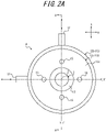
FIG. 2A is a plan view of a light emitter in the gas analyzer illustrated inFIG. 1 ; and -
FIG. 2B is a cross-sectional view along the A-A line inFIG. 2A . - Embodiments of the present disclosure are described below with reference to the drawings.
- As illustrated in
FIG. 1 , a gas analyzer 1 according to the present embodiment uses Tunable Diode Laser Absorption Spectroscopy (TDLAS), for example, to measure a plurality of predetermined components in ameasurement gas 3 by irradiating light 4 from a plurality oflight emitting elements 2 on themeasurement gas 3 and receiving the light 4 that passes through themeasurement gas 3. - Tunable Diode Laser Absorption Spectroscopy (TDLAS) is a method of measuring the concentration, for example, of a predetermined component in a
measurement gas 3 based on the optical path length in themeasurement gas 3 and the intensity difference, i.e., the absorbance, of a specific wavelength component of the light 4 before and after the light 4 passes through themeasurement gas 3. Examples of the predetermined component include CO, CO2, H2O, CnHm, NH3, and O2. - In the present embodiment, the gas analyzer 1 includes a plurality of light transmitters/receivers 6, each including a
light emitting element 2, such as a laser diode, and a light receiving element 5, such as a photodiode, that receives light 4 irradiated from thelight emitting element 2. The gas analyzer 1 also includes a reflector 7 that reflects the light 4 irradiated by the plurality oflight emitting elements 2 so that the light 4 travels back and forth in themeasurement gas 3. According to the plurality of light transmitters/receivers 6, a plurality of predetermined components in themeasurement gas 3 can be measured. The number of light transmitters/receivers 6 is two in the present embodiment, but this example is not limiting, and the number can be increased or decreased as appropriate. - Each light transmitter/receiver 6 is housed in a
first housing 8. Thefirst housing 8 is mounted, via analignment flange 10, on a cylindrical channel wall 9 that forms a channel for themeasurement gas 3. Thefirst housing 8 is angularly adjustable with respect to the channel wall 9 by adjustment of the alignment flange 10 (see the bold arrow inFIG. 1 ). By angular adjustment of thealignment flange 10, the optical axes of the plurality oflight emitting elements 2 can be angularly adjusted together. - The reflector 7 is formed by an optical element such as a retroreflector that reflects the light 4. The reflector 7 is housed in a
second housing 11 in an angularly adjustable manner. Thesecond housing 11 is mounted on the channel wall 9 separately from thefirst housing 8. The optical path length in themeasurement gas 3 can be doubled by the reflector 7, thereby increasing the measurement accuracy. - As described above, the gas analyzer 1 according to the present embodiment is an opposing type that includes two mounting portions (the
first housing 8 and the second housing 11) that face each other across a channel. The gas analyzer 1 is also a reflecting type that includes the reflector 7 and is a multiple optical axis type that includes the plurality oflight emitting elements 2. Opposing types, reflecting types and multiple optical axis types tend to have a higher degree of difficulty in alignment, and the gas analyzer 1 according to the present embodiment, which falls under all of these types, tends to have a particularly high degree of difficulty in alignment. - To address this, the gas analyzer 1 according to the present embodiment is configured so that the positions and angles (directions) of the plurality of optical axes can be adjusted independently of each other to facilitate alignment. More specifically, the gas analyzer 1 includes a plurality of
light emitters 14 that each include abase member 12, aholding member 13, and thelight emitting element 2. Since thelight emitters 14 have similar configurations, onelight emitter 14 is illustrated in detail below. - As illustrated in
FIGS. 2A and2B , the holdingmember 13 holds thelight emitting element 2. Thelight emitting element 2 emits light 4 along an optical axis. The axis coinciding with the optical axis is referred to below as the Z-axis. The holdingmember 13 has an annular shape centered on the Z-axis and integrally holds thelight emitting element 2 at the inner circumferential edge of the holdingmember 13. The holdingmember 13 has acontact surface 13a that is annular, centered on the Z-axis, and that forms a shape along a spherical surface having a spherical center O on the Z-axis. - The
base member 12 has an annular shape centered on the Z-axis when the holdingmember 13 is in the neutral position illustrated inFIG. 2B . The neutral position refers to a position at which the Z-axis is perpendicular to both the below-described X-direction and the below-described Y-direction. More specifically, thebase member 12 includes areceptive member 12b, which has a contactedsurface 12a contacted by thecontact surface 13a of the holdingmember 13, and aframe member 12c integrally attached to thereceptive member 12b. The contactedsurface 12a has an annular shape centered on the Z-axis when the holdingmember 13 is in the neutral position and forms a shape along a spherical surface that defines the shape of thecontact surface 13a. Theframe member 12c has an opposingwall 12d that, when the holdingmember 13 is in the neutral position, faces the contactedsurface 12a in the Z-direction along the Z-axis and has an annular shape centered on the Z axis. - Two X'-axis adjustment screws 15, provided along the Y'-axis on opposite sides of the Z-axis as viewed in the Z-direction when the holding
member 13 is in the neutral position, are attached to the opposingwall 12d in a manner enabling forward and backward movement in the Z-direction when the holdingmember 13 is in the neutral position. Here, the X'-axis and Y'-axis each pass through the spherical center O, and when the holdingmember 13 is in the neutral position, the X'-axis and Y'-axis each intersect the Z-axis at right angles and intersect each other at right angles. The holdingmember 13 is sandwiched between the tips of the two X'-axis adjustment screws 15 and the contactedsurface 12a. Therefore, by adjustment of the Z-direction positions of the two X'-axis adjustment screws 15 (i.e., when one X'-axis adjustment screw 15 is moved backward while the other X'-axis adjustment screw 15 is moved forward), the holdingmember 13 and thelight emitting element 2 held by the holdingmember 13 are rotated around the X'-axis, thereby adjusting the angle of the optical axis around the X'-axis (adjustment of the inclination angle of the optical axis relative to the optical axis in the neutral position). - Two Y'-axis adjustment screws 16, provided along the X'-axis on opposite sides of the Z-axis as viewed in the Z-direction when the holding
member 13 is in the neutral position, are attached to the opposingwall 12d in a manner enabling forward and backward movement in the Z-direction when the holdingmember 13 is in the neutral position. The holdingmember 13 is sandwiched between the tips of the two Y'-axis adjustment screws 16 and the contactedsurface 12a. Therefore, by adjustment of the Z-direction positions of the two Y'-axis adjustment screws 16 (i.e., when one Y'-axis adjustment screw 16 is moved backward while the other Y'-axis adjustment screw 16 is moved forward), the holdingmember 13 and thelight emitting element 2 held by the holdingmember 13 are rotated around the Y'-axis, thereby adjusting the angle of the optical axis around the Y'-axis. - Instead of both the
contact surface 13a and the contactedsurface 12a having shapes along a spherical surface, only one of thecontact surface 13a and the contactedsurface 12a may have a shape along a spherical surface. Furthermore, inFIG. 2B , thelight emitting element 2 is held facing left (to emit the light 4 to the left) by the holding member 13 (i.e., so that the X'-axis adjustment screws 15 and the Y'-axis adjustment screws 16 are on the front side of the light emitting element 2). Alternatively, while maintaining the orientation of the holdingmember 13 inFIG. 2B , thelight emitting element 2 may be faced to the right and held by the holding member 13 (i.e., so that the X'-axis adjustment screws 15 and the Y'-axis adjustment screws 16 are on the back side of the light emitting element 2). - The
base member 12 is held by thefirst housing 8 in a positionally adjustable manner along the X-axis and Y-axis, which are two axes that each intersect the Z-axis at right angles and intersect each other at right angles when the holdingmember 13 is in the neutral position. For example, thebase member 12 is adjustable in position along the X-direction via an X-direction adjustment screw 17 that can move forward and backward in the X-direction along the X-axis and is adjustable in position along the Y-direction via a Y-direction adjustment screw 18 that can move forward and backward in the Y-direction along the Y-axis. The X-axis and X'-axis are parallel to each other, and the Y-axis and Y'-axis are parallel to each other. - In this way, the optical axes can be moved in parallel by adjusting the position of the
base member 12, and the optical axes can be inclined by adjusting the angle of the holdingmember 13. - As described above, the opposing, reflecting, and multiple optical axis type gas analyzer 1 according to the present embodiment includes a plurality of
light emitters 14 that can adjust the position and angle of the optical axes independently of each other, thereby achieving easy alignment. - The above embodiment is an example of the present disclosure, and a variety of modifications may be made.
- For example, the gas analyzer 1 according to the above embodiment can be modified in various ways, as described below.
- Various modifications can be made to the gas analyzer 1 according to the above embodiment, as long as the gas analyzer 1 is for measuring a predetermined component in the
measurement gas 3 by irradiating light 4 on themeasurement gas 3 from thelight emitting element 2 and receiving the light 4 transmitted through themeasurement gas 3, and as long as the gas analyzer 1 includes thebase member 12 configured to be adjustable in position along at least one axis that is not parallel to the optical axis of thelight emitting element 2, and the holdingmember 13 configured to hold thelight emitting element 2 and to be held to thebase member 12 in an angularly adjustable manner around at least one axis that is not parallel to the optical axis. - For example, the gas analyzer 1 according to the above embodiment includes two light emitting
elements 2, but this configuration is not limiting. The gas analyzer 1 may include onelight emitting element 2 or may include three or morelight emitting elements 2. - In the gas analyzer 1 according to the above embodiment, the
base member 12 is adjustable in position along two axes (the X-axis and Y-axis), but thebase member 12 may be adjustable in position along one axis, or thebase member 12 may be adjustable in position along three or more axes. In the gas analyzer 1 according to the above embodiment, the X-axis and the Y-axis are orthogonal, but this configuration is not limiting. The X-axis and the Y-axis may intersect at an angle other than a right angle. - In the gas analyzer 1 according to the above embodiment, the holding
member 13 is adjustable in angle around two axes (the X'-axis and Y'-axis), but this configuration is not limiting. The holdingmember 13 may be adjustable in angle around one axis or may be adjustable in angle around three or more axes. In the gas analyzer 1 according to the above embodiment, the X'-axis and the Y'-axis are orthogonal, but this configuration is not limiting. The X'-axis and the Y'-axis may intersect at an angle other than a right angle. In the gas analyzer 1 according to the above embodiment, the X-axis and the X'-axis are parallel to each other, but this configuration is not limiting. In the gas analyzer 1 according to the above embodiment, the Y-axis and the Y'-axis are parallel to each other, but this configuration is not limiting. - The gas analyzer 1 according to the above embodiment is a reflecting type that includes the reflector 7, but this configuration is not limiting. The gas analyzer 1 may be a non-reflecting, opposing type in which the
light emitting element 2 and the light receiving element 5 are mounted facing each other across a channel. The gas analyzer 1 according to the above embodiment is an opposing type, but this configuration is not limiting. The gas analyzer 1 may be a probe type in which only one part is attached to the channel wall 9, with the reflector 7 being arranged in the channel. - The gas analyzer 1 according to the above embodiment is preferably a gas analyzer 1 including a plurality of
light emitters 14 that each include thebase member 12, the holdingmember 13, and thelight emitting element 2. - The gas analyzer 1 according to the above embodiment is preferably a gas analyzer 1 including the reflector 7 that reflects the light 4 irradiated by the
light emitting element 2 so that the light 4 travels back and forth in themeasurement gas 3. - The gas analyzer 1 according to the above embodiment is preferably a gas analyzer 1 in which the
light emitter 14 and the reflector 7 are separately mounted on the channel wall 9 forming the channel for themeasurement gas 3, thelight emitter 14 including thebase member 12, the holdingmember 13, and thelight emitting element 2, and the reflector 7 being configured to reflect the light 4 irradiated by thelight emitting element 2 so that the light 4 travels back and forth in themeasurement gas 3. - The gas analyzer 1 according to the above embodiment is preferably a gas analyzer 1 in which the holding
member 13 is held to thebase member 12 in an angularly adjustable manner around at least two axes that are not parallel to the optical axis. - The gas analyzer 1 according to the above embodiment is preferably a gas analyzer 1 in which the
base member 12 is adjustable in position along at least two axes that are not parallel to the optical axis. - The gas analyzer 1 according to the above embodiment is preferably a gas analyzer 1 that uses TDLAS.
- The gas analyzer 1 according to the above embodiment is preferably a gas analyzer 1 in which the holding
member 13 is held to thebase member 12 in an angularly adjustable manner around at least one axis that intersects the optical axis. - The gas analyzer 1 according to the above embodiment is preferably a gas analyzer 1 in which the holding
member 13 is held to thebase member 12 in an angularly adjustable manner around two axes that each intersect the optical axis and that intersect each other. - The gas analyzer 1 according to the above embodiment is preferably a gas analyzer 1 in which the
base member 12 is adjustable in position along at least one axis that intersects the optical axis. - The gas analyzer 1 according to the above embodiment is preferably a gas analyzer 1 in which the
base member 12 is adjustable in position along two axes that each intersect the optical axis and that intersect each other.
Claims (7)
- A gas analyzer for measuring a predetermined component in a measurement gas by irradiating light on the measurement gas from a light emitting element and receiving light that passes through the measurement gas, the gas analyzer comprising:a base member configured to be adjustable in position along at least one axis that is not parallel to an optical axis of the light emitting element; anda holding member configured to hold the light emitting element and to be held to the base member in an angularly adjustable manner around at least one axis that is not parallel to the optical axis.
- The gas analyzer of claim 1, further comprising a plurality of light emitters that each include the base member, the holding member, and the light emitting element.
- The gas analyzer of claim 1 or 2, further comprising a reflector configured to reflect the light irradiated by the light emitting element so that the light travels back and forth in the measurement gas.
- The gas analyzer of any one of claims 1 to 3, wherein a light emitter and a reflector are separately mounted on a channel wall forming a channel for the measurement gas, the light emitter comprising the base member, the holding member, and the light emitting element, and the reflector being configured to reflect the light irradiated by the light emitting element so that the light travels back and forth in the measurement gas.
- The gas analyzer of any one of claims 1 to 4, wherein the holding member is held to the base member in an angularly adjustable manner around at least two axes that are not parallel to the optical axis.
- The gas analyzer of any one of claims 1 to 5, wherein the base member is adjustable in position along at least two axes that are not parallel to the optical axis.
- The gas analyzer of any one of claims 1 to 6, wherein the gas analyzer uses tunable diode laser absorption spectroscopy.
Applications Claiming Priority (1)
| Application Number | Priority Date | Filing Date | Title |
|---|---|---|---|
| JP2021058447A JP7298640B2 (en) | 2021-03-30 | 2021-03-30 | gas analyzer |
Publications (2)
| Publication Number | Publication Date |
|---|---|
| EP4067876A1 true EP4067876A1 (en) | 2022-10-05 |
| EP4067876B1 EP4067876B1 (en) | 2025-10-08 |
Family
ID=80933140
Family Applications (1)
| Application Number | Title | Priority Date | Filing Date |
|---|---|---|---|
| EP22164144.2A Active EP4067876B1 (en) | 2021-03-30 | 2022-03-24 | Gas analyzer |
Country Status (4)
| Country | Link |
|---|---|
| US (1) | US11774358B2 (en) |
| EP (1) | EP4067876B1 (en) |
| JP (1) | JP7298640B2 (en) |
| CN (1) | CN115144366B (en) |
Families Citing this family (1)
| Publication number | Priority date | Publication date | Assignee | Title |
|---|---|---|---|---|
| EP4677339A1 (en) * | 2023-03-07 | 2026-01-14 | Yokogawa Electric Corporation | Gas analyzer |
Citations (4)
| Publication number | Priority date | Publication date | Assignee | Title |
|---|---|---|---|---|
| US5303035A (en) * | 1992-05-04 | 1994-04-12 | New Focus, Inc. | Precision micropositioner |
| US20140211209A1 (en) * | 2011-08-12 | 2014-07-31 | Horiba, Ltd. | Gas analysis apparatus |
| CN109540800A (en) * | 2018-12-27 | 2019-03-29 | 皖江新兴产业技术发展中心 | A kind of laser multiple reflectance cell for high-temperature gas detection |
| US20190310188A1 (en) * | 2018-04-06 | 2019-10-10 | Yokogawa Electric Corporation | Gas analysis device |
Family Cites Families (12)
| Publication number | Priority date | Publication date | Assignee | Title |
|---|---|---|---|---|
| JPS59226309A (en) * | 1983-06-07 | 1984-12-19 | Fujitsu Ltd | Sticking structure of optical transmission path parts |
| US4655548A (en) * | 1984-10-22 | 1987-04-07 | Grumman Aerospace Corporation | Multi-degree of freedom mount |
| JP2000171736A (en) * | 1998-12-08 | 2000-06-23 | Sankyo Seiki Mfg Co Ltd | Optical transmission module and optical transmission system |
| JP2000206045A (en) * | 1999-01-18 | 2000-07-28 | Horiba Ltd | In-line monitor |
| JP2002286969A (en) * | 2001-03-28 | 2002-10-03 | Seiko Instruments Inc | Collimator block for optical function module |
| JP2003022542A (en) * | 2001-07-10 | 2003-01-24 | Nec Corp | Fixing mechanism of semiconductor laser and optical head device |
| JP5583374B2 (en) * | 2009-09-07 | 2014-09-03 | 株式会社島津製作所 | Photo-curing resin characteristic testing device, holder used in the testing device, and characteristic testing method |
| DE102012104008B3 (en) * | 2012-05-08 | 2013-11-07 | Jenoptik Industrial Metrology Germany Gmbh | Apparatus and method for measuring shape, position and dimension features on machine elements |
| CN103884677B (en) * | 2012-12-19 | 2017-05-03 | 北京大方科技有限责任公司 | Gas analyzer sample gas chamber apparatus with characteristic of easy optical path adjustment |
| WO2016174759A1 (en) * | 2015-04-30 | 2016-11-03 | 富士電機株式会社 | Laser-type gas analyzer |
| JP2019184523A (en) * | 2018-04-16 | 2019-10-24 | 横河電機株式会社 | Gas analyser |
| JP6777116B2 (en) * | 2018-05-11 | 2020-10-28 | 横河電機株式会社 | Laser gas analyzer |
-
2021
- 2021-03-30 JP JP2021058447A patent/JP7298640B2/en active Active
-
2022
- 2022-03-24 EP EP22164144.2A patent/EP4067876B1/en active Active
- 2022-03-25 US US17/656,576 patent/US11774358B2/en active Active
- 2022-03-29 CN CN202210316164.XA patent/CN115144366B/en active Active
Patent Citations (4)
| Publication number | Priority date | Publication date | Assignee | Title |
|---|---|---|---|---|
| US5303035A (en) * | 1992-05-04 | 1994-04-12 | New Focus, Inc. | Precision micropositioner |
| US20140211209A1 (en) * | 2011-08-12 | 2014-07-31 | Horiba, Ltd. | Gas analysis apparatus |
| US20190310188A1 (en) * | 2018-04-06 | 2019-10-10 | Yokogawa Electric Corporation | Gas analysis device |
| CN109540800A (en) * | 2018-12-27 | 2019-03-29 | 皖江新兴产业技术发展中心 | A kind of laser multiple reflectance cell for high-temperature gas detection |
Also Published As
| Publication number | Publication date |
|---|---|
| CN115144366B (en) | 2025-06-24 |
| CN115144366A (en) | 2022-10-04 |
| JP7298640B2 (en) | 2023-06-27 |
| US20220317040A1 (en) | 2022-10-06 |
| EP4067876B1 (en) | 2025-10-08 |
| US11774358B2 (en) | 2023-10-03 |
| JP2022155108A (en) | 2022-10-13 |
Similar Documents
| Publication | Publication Date | Title |
|---|---|---|
| KR102532406B1 (en) | gas monitor | |
| KR102482997B1 (en) | gas monitor | |
| US20080316463A1 (en) | Laser radar apparatus that measures direction and distance of an object | |
| US20020178595A1 (en) | Method of producing a precise horizontal or vertical laser line beam drawn on objectives, and apparatus thereof | |
| JP2010243270A (en) | Combined multipass cell and gas meter | |
| US10712430B2 (en) | Optical system of laser scanner and surveying instrument | |
| EP1471565B1 (en) | Mapping device for semiconductor wafers | |
| EP4067876B1 (en) | Gas analyzer | |
| JP3793315B2 (en) | Tilt detection device | |
| US20180149749A1 (en) | Device for Optically Measuring the Distance from a Reflective Target Object | |
| EP2722705B1 (en) | Optical assembly and laser alignment apparatus | |
| JP4652921B2 (en) | Sample holder | |
| US11181475B2 (en) | Gas analysis device | |
| EP1956391A2 (en) | Laser radar apparatus that measures direction and distance of an object | |
| CN101300475A (en) | laser radiation source | |
| CN220490676U (en) | Supporting device of optical cavity ring-down light path system and optical cavity ring-down light path system | |
| CN221224570U (en) | A gas sensor with adaptive reflection of infrared parallel beam | |
| US20140111866A1 (en) | Optical assembly and laser alignment apparatus | |
| TWI873547B (en) | Lidar gesture calibration apparatus and method | |
| US20250258086A1 (en) | Light source unit | |
| JPH08114671A (en) | Laser rangefinding apparatus | |
| EP3492882B1 (en) | Liquid level detection sensor and specimen testing apparatus | |
| CN112596098A (en) | Centering device and centering method for transmission crystal spectrometer | |
| JP2026500524A (en) | Multipath spectroscopic absorption cell and gas sensor including the same | |
| JP2005079126A (en) | Optical fiber sensor head, its manufacturing process and wafer detector |
Legal Events
| Date | Code | Title | Description |
|---|---|---|---|
| PUAI | Public reference made under article 153(3) epc to a published international application that has entered the european phase |
Free format text: ORIGINAL CODE: 0009012 |
|
| STAA | Information on the status of an ep patent application or granted ep patent |
Free format text: STATUS: THE APPLICATION HAS BEEN PUBLISHED |
|
| AK | Designated contracting states |
Kind code of ref document: A1 Designated state(s): AL AT BE BG CH CY CZ DE DK EE ES FI FR GB GR HR HU IE IS IT LI LT LU LV MC MK MT NL NO PL PT RO RS SE SI SK SM TR |
|
| STAA | Information on the status of an ep patent application or granted ep patent |
Free format text: STATUS: REQUEST FOR EXAMINATION WAS MADE |
|
| 17P | Request for examination filed |
Effective date: 20230328 |
|
| RBV | Designated contracting states (corrected) |
Designated state(s): AL AT BE BG CH CY CZ DE DK EE ES FI FR GB GR HR HU IE IS IT LI LT LU LV MC MK MT NL NO PL PT RO RS SE SI SK SM TR |
|
| P01 | Opt-out of the competence of the unified patent court (upc) registered |
Effective date: 20230606 |
|
| STAA | Information on the status of an ep patent application or granted ep patent |
Free format text: STATUS: EXAMINATION IS IN PROGRESS |
|
| 17Q | First examination report despatched |
Effective date: 20231213 |
|
| GRAP | Despatch of communication of intention to grant a patent |
Free format text: ORIGINAL CODE: EPIDOSNIGR1 |
|
| STAA | Information on the status of an ep patent application or granted ep patent |
Free format text: STATUS: GRANT OF PATENT IS INTENDED |
|
| RIC1 | Information provided on ipc code assigned before grant |
Ipc: G01N 21/03 20060101ALN20250530BHEP Ipc: G01B 5/00 20060101ALI20250530BHEP Ipc: G01N 21/85 20060101ALI20250530BHEP Ipc: G01N 21/39 20060101AFI20250530BHEP |
|
| INTG | Intention to grant announced |
Effective date: 20250616 |
|
| RAP3 | Party data changed (applicant data changed or rights of an application transferred) |
Owner name: YOKOGAWA ELECTRIC CORPORATION |
|
| GRAS | Grant fee paid |
Free format text: ORIGINAL CODE: EPIDOSNIGR3 |
|
| GRAA | (expected) grant |
Free format text: ORIGINAL CODE: 0009210 |
|
| STAA | Information on the status of an ep patent application or granted ep patent |
Free format text: STATUS: THE PATENT HAS BEEN GRANTED |
|
| AK | Designated contracting states |
Kind code of ref document: B1 Designated state(s): AL AT BE BG CH CY CZ DE DK EE ES FI FR GB GR HR HU IE IS IT LI LT LU LV MC MK MT NL NO PL PT RO RS SE SI SK SM TR |
|
| REG | Reference to a national code |
Ref country code: GB Ref legal event code: FG4D Ref country code: CH Ref legal event code: F10 Free format text: ST27 STATUS EVENT CODE: U-0-0-F10-F00 (AS PROVIDED BY THE NATIONAL OFFICE) Effective date: 20251008 |
|
| REG | Reference to a national code |
Ref country code: DE Ref legal event code: R096 Ref document number: 602022022560 Country of ref document: DE |
|
| REG | Reference to a national code |
Ref country code: IE Ref legal event code: FG4D |
|
| REG | Reference to a national code |
Ref country code: NL Ref legal event code: MP Effective date: 20251008 |
|
| REG | Reference to a national code |
Ref country code: AT Ref legal event code: MK05 Ref document number: 1845190 Country of ref document: AT Kind code of ref document: T Effective date: 20251008 |
|
| PG25 | Lapsed in a contracting state [announced via postgrant information from national office to epo] |
Ref country code: NL Free format text: LAPSE BECAUSE OF FAILURE TO SUBMIT A TRANSLATION OF THE DESCRIPTION OR TO PAY THE FEE WITHIN THE PRESCRIBED TIME-LIMIT Effective date: 20251008 |
|
| PG25 | Lapsed in a contracting state [announced via postgrant information from national office to epo] |
Ref country code: ES Free format text: LAPSE BECAUSE OF FAILURE TO SUBMIT A TRANSLATION OF THE DESCRIPTION OR TO PAY THE FEE WITHIN THE PRESCRIBED TIME-LIMIT Effective date: 20251008 |
|
| REG | Reference to a national code |
Ref country code: LT Ref legal event code: MG9D |
|
| PG25 | Lapsed in a contracting state [announced via postgrant information from national office to epo] |
Ref country code: NO Free format text: LAPSE BECAUSE OF FAILURE TO SUBMIT A TRANSLATION OF THE DESCRIPTION OR TO PAY THE FEE WITHIN THE PRESCRIBED TIME-LIMIT Effective date: 20260108 |
|
| PGFP | Annual fee paid to national office [announced via postgrant information from national office to epo] |
Ref country code: DE Payment date: 20260326 Year of fee payment: 5 |
|
| PG25 | Lapsed in a contracting state [announced via postgrant information from national office to epo] |
Ref country code: HR Free format text: LAPSE BECAUSE OF FAILURE TO SUBMIT A TRANSLATION OF THE DESCRIPTION OR TO PAY THE FEE WITHIN THE PRESCRIBED TIME-LIMIT Effective date: 20251008 Ref country code: FI Free format text: LAPSE BECAUSE OF FAILURE TO SUBMIT A TRANSLATION OF THE DESCRIPTION OR TO PAY THE FEE WITHIN THE PRESCRIBED TIME-LIMIT Effective date: 20251008 Ref country code: AT Free format text: LAPSE BECAUSE OF FAILURE TO SUBMIT A TRANSLATION OF THE DESCRIPTION OR TO PAY THE FEE WITHIN THE PRESCRIBED TIME-LIMIT Effective date: 20251008 |
|
| PG25 | Lapsed in a contracting state [announced via postgrant information from national office to epo] |
Ref country code: RS Free format text: LAPSE BECAUSE OF FAILURE TO SUBMIT A TRANSLATION OF THE DESCRIPTION OR TO PAY THE FEE WITHIN THE PRESCRIBED TIME-LIMIT Effective date: 20260108 |
|
| PG25 | Lapsed in a contracting state [announced via postgrant information from national office to epo] |
Ref country code: IS Free format text: LAPSE BECAUSE OF FAILURE TO SUBMIT A TRANSLATION OF THE DESCRIPTION OR TO PAY THE FEE WITHIN THE PRESCRIBED TIME-LIMIT Effective date: 20260208 |
|
| PG25 | Lapsed in a contracting state [announced via postgrant information from national office to epo] |
Ref country code: PT Free format text: LAPSE BECAUSE OF FAILURE TO SUBMIT A TRANSLATION OF THE DESCRIPTION OR TO PAY THE FEE WITHIN THE PRESCRIBED TIME-LIMIT Effective date: 20260209 |
|
| PG25 | Lapsed in a contracting state [announced via postgrant information from national office to epo] |
Ref country code: PL Free format text: LAPSE BECAUSE OF FAILURE TO SUBMIT A TRANSLATION OF THE DESCRIPTION OR TO PAY THE FEE WITHIN THE PRESCRIBED TIME-LIMIT Effective date: 20251008 |
|
| PG25 | Lapsed in a contracting state [announced via postgrant information from national office to epo] |
Ref country code: LV Free format text: LAPSE BECAUSE OF FAILURE TO SUBMIT A TRANSLATION OF THE DESCRIPTION OR TO PAY THE FEE WITHIN THE PRESCRIBED TIME-LIMIT Effective date: 20251008 |
|
| PG25 | Lapsed in a contracting state [announced via postgrant information from national office to epo] |
Ref country code: BG Free format text: LAPSE BECAUSE OF FAILURE TO SUBMIT A TRANSLATION OF THE DESCRIPTION OR TO PAY THE FEE WITHIN THE PRESCRIBED TIME-LIMIT Effective date: 20251008 |