EP4067839A1 - Vibration-based directional synthetic ambient sound production in space - Google Patents
Vibration-based directional synthetic ambient sound production in space Download PDFInfo
- Publication number
- EP4067839A1 EP4067839A1 EP22161137.9A EP22161137A EP4067839A1 EP 4067839 A1 EP4067839 A1 EP 4067839A1 EP 22161137 A EP22161137 A EP 22161137A EP 4067839 A1 EP4067839 A1 EP 4067839A1
- Authority
- EP
- European Patent Office
- Prior art keywords
- vibration
- speakers
- audio
- controller
- frequency
- Prior art date
- Legal status (The legal status is an assumption and is not a legal conclusion. Google has not performed a legal analysis and makes no representation as to the accuracy of the status listed.)
- Granted
Links
Images
Classifications
-
- G—PHYSICS
- G01—MEASURING; TESTING
- G01H—MEASUREMENT OF MECHANICAL VIBRATIONS OR ULTRASONIC, SONIC OR INFRASONIC WAVES
- G01H9/00—Measuring mechanical vibrations or ultrasonic, sonic or infrasonic waves by using radiation-sensitive means, e.g. optical means
-
- A—HUMAN NECESSITIES
- A41—WEARING APPAREL
- A41D—OUTERWEAR; PROTECTIVE GARMENTS; ACCESSORIES
- A41D1/00—Garments
- A41D1/002—Garments adapted to accommodate electronic equipment
-
- B—PERFORMING OPERATIONS; TRANSPORTING
- B64—AIRCRAFT; AVIATION; COSMONAUTICS
- B64G—COSMONAUTICS; VEHICLES OR EQUIPMENT THEREFOR
- B64G6/00—Space suits
Definitions
- Exemplary embodiments pertain to the art of audio generation and, in particular, to vibration-based directional synthetic ambient sound production in space.
- Ambient sound refers to the sound present in a scene or location.
- the sounds of birds, leaves rustling, or a waterfall represent ambient sounds.
- traffic noises represent ambient sound.
- Humans detect ambient sounds through vibrations in the air. For example, wind causes vibration (i.e., rustling) of leaves, and the vibration is perceived as ambient sound.
- there is no medium to transmit sound i.e., sound waves cannot travel in space or on the surface of the moon.
- astronauts do not receive audible signals from the surroundings in the form of ambient sound.
- a system in one embodiment, includes a vibration detector to detect a location of vibration and identify a frequency of the vibration.
- the system also includes a controller to generate audio corresponding to the frequency of vibration detected by the vibration detector, and one or more speakers configured to provide the audio as directional sound.
- the system is on or within an atmospheric suit that is configured for a space environment.
- the one or more speakers are within a helmet of the atmospheric suit.
- the one or more speakers is an array of four or more speakers arranged around a volume within the helmet.
- the array of four or more speakers and the vibration detector have a fixed positional relationship.
- the one or more speakers are in headphones.
- the vibration detector is part of an image sensor that includes a three-dimensional camera.
- the vibration detector is a three-dimensional laser Doppler vibrometer.
- the controller generates the audio as synthetic ambient sound that corresponds with the frequency of the vibration.
- the controller generates the audio based on a mapping between the frequency of the vibration and the audio or based on machine learning.
- a method in another embodiment, includes attaching a vibration detector to an atmospheric suit for a space environment.
- the vibration detector detects a location of vibration and identifies a frequency of the vibration.
- the method also includes disposing a controller coupled to the vibration detector to generate audio corresponding to the frequency of vibration detected by the vibration detector, and disposing one or more speakers in the atmospheric suit to receive the audio from the controller and to provide the audio as directional sound to a wearer of the atmospheric suit.
- the disposing the one or more speakers is within a helmet of the atmospheric suit.
- the disposing the one or more speakers is as an array of four or more speakers arranged around a volume within the helmet.
- disposing the array of four or more speakers includes establishing a fixed positional relationship with the vibration detector.
- the disposing the one or more speakers is in headphones.
- the method also includes attaching an image sensor that includes the vibration detector and a three-dimensional camera.
- the attaching the vibration detector is as a three-dimensional laser Doppler vibrometer.
- the method also includes configuring the controller to generate the audio as synthetic ambient sound that corresponds with the frequency of the vibration.
- the method also includes configuring the controller to generate the audio based on a mapping between the frequency of the vibration and the audio or based on machine learning.
- exemplary sources of ambient sound include loose soil on which the astronaut is walking or rolling rocks.
- Ambient sounds can provide situational awareness and can also provide warnings.
- the ambient sound representing the rolling of a large rock toward the astronaut can serve as a warning to move out of the way.
- Embodiments of the systems and methods detailed herein relate to vibration-based directional synthetic ambient sound production in space.
- Ambient sound is generated synthetically based on vibrations detected in the environment.
- the ambient sound is presented to the astronaut as directional sound to facilitate situational awareness as though the astronaut were in an environment in which ambient sounds could be heard. That is, the ambient sound that is generated is what would be heard if there were a medium to transmit the sound.
- One or more sensors are used to detect vibrations in the environment. These vibrations are used to generate synthetic ambient sound that is audible to the astronaut and is presented as directional audio, as further detailed.
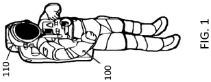
- FIG. 1 shows aspects of an atmospheric suit 100 with a helmet 110 that provides vibration-based directional ambient sound production according to one or more embodiments.
- the atmospheric suit 100 may be an extravehicular mobility unit (EMU) used in a space application, as one example.
- the helmet 110 provides a volume 115 ( FIG. 2 ) to accommodate the head of a wearer of the atmospheric suit 100.
- the helmet 110 includes an inner bubble that maintains the gasses of the atmospheric suit 100 to create an environment to sustain the wearer.
- the helmet 110 may include one or more speakers 210 that output audio that simulates ambient sound that cannot actually be heard in the space environment.
- the one or more speakers 210 provide the audio with directionality.
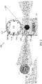
- FIG. 2 is a system 200 for vibration-based directional synthetic ambient sound production in space according to one or more embodiments.
- a cross-sectional view of the helmet 110 is shown such that an array of speakers 210 is exposed.
- directional earphones may be worn by the astronaut in the atmospheric suit 100.
- a sensor 220 includes a vibrometer (e.g., three-dimensional laser Doppler vibrometer) that detects vibration.
- the system 200 may also include a camera that facilitates identification and tracking of objects (e.g., rolling rock) using known image processing techniques.
- the sensor 220 may include a three-dimensional camera that supports six degrees of freedom (6Dof).
- the vibrometer and camera, together, are referred to as an image sensor 225.
- the field of view of the sensor 220 which may be comprised of an array of image sensors 225, is 360 degrees and over a range of elevations. That is, adjacent image sensors 225 may have overlapping fields of view such that the sensor 220 with an array of the image sensors 225 is coupled to the atmospheric suit 100 and detects vibration at an identifiable relative location in the environment around the atmospheric suit 100.
- more than one sensor 220 may be used to sense vibrations all around the astronaut (e.g., vibration of the lunar surface below the astronaut's feet, vibration caused by a rock rolling down toward the astronaut).
- One or more sensors 220 (e.g., one or more arrays of image sensors 225) provide vibration frequency and location information to a controller 230.
- the controller 230 determines an audio signal that represents the ambient sound corresponding with the frequency of vibration (i.e., synthetic ambient sound).
- the controller 230 may use a mapping of a range of frequencies of vibration to a frequency (i.e., pitch) of an audio signal, for example.
- the controller 230 may learn an earth-based correspondence between vibration and audio output in a machine learning process to determine the synthetic ambient sound that corresponds with detected vibrations. That is, because the vibration is carried by an air medium to produce sound waves on earth, the correspondence between vibration and sound may be used in a supervised learning process.
- the sensor 220 and controller 230 together, represent a directional audio generation system 235.
- the same sound may be produced for any vibration or a synthetic non-ambient sound may be generated based on a frequency of the vibration. Movement of the vibration may be a factor in determining the non-ambient sound (e.g., alarm tone). For example, if the location of the vibration is moving toward the sensor 220 of the atmospheric suit 100 (e.g., as in the rolling rock scenario illustrated in FIG. 2 ), the synthetic sound may reflect that the situation requires immediate attention from the wearer of the atmospheric suit 100.
- the non-ambient sound e.g., alarm tone
- a reference point 215 is indicated on the helmet 110 and the sensor 220.
- the relationship between the helmet 110 and the sensor 220 and, thus, between their respective reference points 215, is fixed.
- the location of the vibration relative to the sensor 220 which is among the information provided to the controller 230, corresponds with the location of ambient sound within the helmet 110.
- an array of speakers 210 may be used to produce the directional sound or directional headphones may be worn by the astronaut, for example.
- a rolling rock to the left of the helmet 110 is the source of vibration detected by the sensor 220.
- the controller 230 generates ambient sound and plays it through the speaker 210x, which is on the left side of the helmet 110, as shown.
- the wearer of the atmospheric suit 100 is readily alerted not only to the presence of the activity but also to its relative position.
Landscapes
- Engineering & Computer Science (AREA)
- Physics & Mathematics (AREA)
- General Physics & Mathematics (AREA)
- Remote Sensing (AREA)
- Aviation & Aerospace Engineering (AREA)
- Textile Engineering (AREA)
- Helmets And Other Head Coverings (AREA)
- Circuit For Audible Band Transducer (AREA)
Abstract
Description
- Exemplary embodiments pertain to the art of audio generation and, in particular, to vibration-based directional synthetic ambient sound production in space.
- Ambient sound refers to the sound present in a scene or location. In nature, for example, the sounds of birds, leaves rustling, or a waterfall represent ambient sounds. In a city, traffic noises represent ambient sound. Humans detect ambient sounds through vibrations in the air. For example, wind causes vibration (i.e., rustling) of leaves, and the vibration is perceived as ambient sound. In space or on the surface of the moon, for example, there is no medium to transmit sound (i.e., sound waves cannot travel in space or on the surface of the moon). Thus, astronauts do not receive audible signals from the surroundings in the form of ambient sound.
- In one embodiment, a system includes a vibration detector to detect a location of vibration and identify a frequency of the vibration. The system also includes a controller to generate audio corresponding to the frequency of vibration detected by the vibration detector, and one or more speakers configured to provide the audio as directional sound.
- Additionally or alternatively, in this or other embodiments, the system is on or within an atmospheric suit that is configured for a space environment.
- Additionally or alternatively, in this or other embodiments, the one or more speakers are within a helmet of the atmospheric suit.
- Additionally or alternatively, in this or other embodiments, the one or more speakers is an array of four or more speakers arranged around a volume within the helmet.
- Additionally or alternatively, in this or other embodiments, the array of four or more speakers and the vibration detector have a fixed positional relationship.
- Additionally or alternatively, in this or other embodiments, the one or more speakers are in headphones.
- Additionally or alternatively, in this or other embodiments, the vibration detector is part of an image sensor that includes a three-dimensional camera.
- Additionally or alternatively, in this or other embodiments, the vibration detector is a three-dimensional laser Doppler vibrometer.
- Additionally or alternatively, in this or other embodiments, the controller generates the audio as synthetic ambient sound that corresponds with the frequency of the vibration.
- Additionally or alternatively, in this or other embodiments, the controller generates the audio based on a mapping between the frequency of the vibration and the audio or based on machine learning.
- In another embodiment, a method includes attaching a vibration detector to an atmospheric suit for a space environment. The vibration detector detects a location of vibration and identifies a frequency of the vibration. The method also includes disposing a controller coupled to the vibration detector to generate audio corresponding to the frequency of vibration detected by the vibration detector, and disposing one or more speakers in the atmospheric suit to receive the audio from the controller and to provide the audio as directional sound to a wearer of the atmospheric suit.
- Additionally or alternatively, in this or other embodiments, the disposing the one or more speakers is within a helmet of the atmospheric suit.
- Additionally or alternatively, in this or other embodiments, the disposing the one or more speakers is as an array of four or more speakers arranged around a volume within the helmet.
- Additionally or alternatively, in this or other embodiments, disposing the array of four or more speakers includes establishing a fixed positional relationship with the vibration detector.
- Additionally or alternatively, in this or other embodiments, the disposing the one or more speakers is in headphones.
- Additionally or alternatively, in this or other embodiments, the method also includes attaching an image sensor that includes the vibration detector and a three-dimensional camera.
- Additionally or alternatively, in this or other embodiments, the attaching the vibration detector is as a three-dimensional laser Doppler vibrometer.
- Additionally or alternatively, in this or other embodiments, the method also includes configuring the controller to generate the audio as synthetic ambient sound that corresponds with the frequency of the vibration.
- Additionally or alternatively, in this or other embodiments, the method also includes configuring the controller to generate the audio based on a mapping between the frequency of the vibration and the audio or based on machine learning.
- The following descriptions should not be considered limiting in any way. With reference to the accompanying drawings, like elements are numbered alike:
-
FIG. 1 shows aspects of an atmospheric suit with a helmet that provides vibration-based directional ambient sound production according to one or more embodiments; and -
FIG. 2 is a system for vibration-based directional synthetic ambient sound production in space according to one or more embodiments. - A detailed description of one or more embodiments of the disclosed apparatus and method are presented herein by way of exemplification and not limitation with reference to the Figures.
- As previously noted, astronauts in space and lunar environments cannot hear ambient sounds. On the lunar surface, exemplary sources of ambient sound include loose soil on which the astronaut is walking or rolling rocks. Ambient sounds can provide situational awareness and can also provide warnings. For example, the ambient sound representing the rolling of a large rock toward the astronaut can serve as a warning to move out of the way.
- Embodiments of the systems and methods detailed herein relate to vibration-based directional synthetic ambient sound production in space. Ambient sound is generated synthetically based on vibrations detected in the environment. The ambient sound is presented to the astronaut as directional sound to facilitate situational awareness as though the astronaut were in an environment in which ambient sounds could be heard. That is, the ambient sound that is generated is what would be heard if there were a medium to transmit the sound. One or more sensors are used to detect vibrations in the environment. These vibrations are used to generate synthetic ambient sound that is audible to the astronaut and is presented as directional audio, as further detailed.
-
FIG. 1 shows aspects of an atmospheric suit 100 with a helmet 110 that provides vibration-based directional ambient sound production according to one or more embodiments. The atmospheric suit 100 may be an extravehicular mobility unit (EMU) used in a space application, as one example. The helmet 110 provides a volume 115 (FIG. 2 ) to accommodate the head of a wearer of the atmospheric suit 100. The helmet 110 includes an inner bubble that maintains the gasses of the atmospheric suit 100 to create an environment to sustain the wearer. As detailed inFIG. 2 , the helmet 110 may include one or more speakers 210 that output audio that simulates ambient sound that cannot actually be heard in the space environment. The one or more speakers 210 provide the audio with directionality. -
FIG. 2 is a system 200 for vibration-based directional synthetic ambient sound production in space according to one or more embodiments. A cross-sectional view of the helmet 110 is shown such that an array of speakers 210 is exposed. According to an exemplary alternate embodiment, directional earphones may be worn by the astronaut in the atmospheric suit 100. A sensor 220 includes a vibrometer (e.g., three-dimensional laser Doppler vibrometer) that detects vibration. The system 200 may also include a camera that facilitates identification and tracking of objects (e.g., rolling rock) using known image processing techniques. The sensor 220 may include a three-dimensional camera that supports six degrees of freedom (6Dof). - The vibrometer and camera, together, are referred to as an image sensor 225. Because the system 200 produces directional sound, the field of view of the sensor 220, which may be comprised of an array of image sensors 225, is 360 degrees and over a range of elevations. That is, adjacent image sensors 225 may have overlapping fields of view such that the sensor 220 with an array of the image sensors 225 is coupled to the atmospheric suit 100 and detects vibration at an identifiable relative location in the environment around the atmospheric suit 100. Based on the location of the sensor 220, more than one sensor 220 may be used to sense vibrations all around the astronaut (e.g., vibration of the lunar surface below the astronaut's feet, vibration caused by a rock rolling down toward the astronaut). One or more sensors 220 (e.g., one or more arrays of image sensors 225) provide vibration frequency and location information to a controller 230.
- The controller 230 determines an audio signal that represents the ambient sound corresponding with the frequency of vibration (i.e., synthetic ambient sound). The controller 230 may use a mapping of a range of frequencies of vibration to a frequency (i.e., pitch) of an audio signal, for example. According to an alternate embodiment, the controller 230 may learn an earth-based correspondence between vibration and audio output in a machine learning process to determine the synthetic ambient sound that corresponds with detected vibrations. That is, because the vibration is carried by an air medium to produce sound waves on earth, the correspondence between vibration and sound may be used in a supervised learning process. The sensor 220 and controller 230, together, represent a directional audio generation system 235.
- According to other alternate embodiments, the same sound may be produced for any vibration or a synthetic non-ambient sound may be generated based on a frequency of the vibration. Movement of the vibration may be a factor in determining the non-ambient sound (e.g., alarm tone). For example, if the location of the vibration is moving toward the sensor 220 of the atmospheric suit 100 (e.g., as in the rolling rock scenario illustrated in
FIG. 2 ), the synthetic sound may reflect that the situation requires immediate attention from the wearer of the atmospheric suit 100. - As previously noted, directionality of the vibration that gives rise to the production of ambient sound provides additional situational awareness for the wearer of the atmospheric suit 100. A reference point 215 is indicated on the helmet 110 and the sensor 220. The relationship between the helmet 110 and the sensor 220 and, thus, between their respective reference points 215, is fixed. As a result, the location of the vibration relative to the sensor 220, which is among the information provided to the controller 230, corresponds with the location of ambient sound within the helmet 110. As previously noted, an array of speakers 210 may be used to produce the directional sound or directional headphones may be worn by the astronaut, for example.
- According to the exemplary orientation shown in
FIG. 2 , a rolling rock to the left of the helmet 110 is the source of vibration detected by the sensor 220. As a result, the controller 230 generates ambient sound and plays it through the speaker 210x, which is on the left side of the helmet 110, as shown. Thus, the wearer of the atmospheric suit 100 is readily alerted not only to the presence of the activity but also to its relative position. - The terminology used herein is for the purpose of describing particular embodiments only and is not intended to be limiting of the present disclosure. As used herein, the singular forms "a", "an" and "the" are intended to include the plural forms as well, unless the context clearly indicates otherwise. It will be further understood that the terms "comprises" and/or "comprising," when used in this specification, specify the presence of stated features, integers, steps, operations, elements, and/or components, but do not preclude the presence or addition of one or more other features, integers, steps, operations, element components, and/or groups thereof.
- While the present disclosure has been described with reference to an exemplary embodiment or embodiments, it will be understood by those skilled in the art that various changes may be made and equivalents may be substituted for elements thereof without departing from the scope of the claims. In addition, many modifications may be made to adapt a particular situation or material to the teachings of the present disclosure without departing from the scope of the claims. Therefore, it is intended that the present disclosure not be limited to the particular embodiment disclosed as the best mode contemplated for carrying out this present disclosure, but that the present disclosure will include all embodiments falling within the scope of the claims.
Claims (15)
- A system (200) comprising:a vibration detector (220) configured to detect a location of vibration and identify a frequency of the vibration;a controller (230) configured to generate audio corresponding to the frequency of vibration detected by the vibration detector; andone or more speakers (210) configured to provide the audio as directional sound.
- The system according to claim 1, wherein the system is on or within an atmospheric suit (100) that is configured for a space environment.
- The system according to claim 2, wherein the one or more speakers are within a helmet (110) of the atmospheric suit.
- The system according to claim 3, wherein the one or more speakers is an array of four or more speakers arranged around a volume within the helmet; optionally wherein the array of four or more speakers and the vibration detector have a fixed positional relationship.
- The system according to claim 3, wherein the one or more speakers are in headphones.
- The system according to any preceding claim, wherein the vibration detector is part of an image sensor that includes a three-dimensional camera; and/or wherein the vibration detector is a three-dimensional laser Doppler vibrometer.
- The system according to any preceding claim, wherein the controller is configured to generate the audio as synthetic ambient sound that corresponds with the frequency of the vibration.
- The system according to any preceding claim, wherein the controller (230) is configured to generate the audio based on a mapping between the frequency of the vibration and the audio or based on machine learning.
- A method comprising:attaching a vibration detector (220) to an atmospheric suit (100) that is configured for a space environment, the vibration detector being configured to detect a location of vibration and identify a frequency of the vibration;disposing a controller (230) coupled to the vibration detector, the controller being configured to generate audio corresponding to the frequency of vibration detected by the vibration detector; anddisposing one or more speakers (210) in the atmospheric suit to receive the audio from the controller and to provide the audio as directional sound to a wearer of the atmospheric suit.
- The method according to claim 9, wherein the disposing the one or more speakers is within a helmet (110) of the atmospheric suit.
- The method according to claim 10, wherein the disposing the one or more speakers is as an array of four or more speakers arranged around a volume within the helmet; optionally wherein disposing the array of four or more speakers includes establishing a fixed positional relationship with the vibration detector.
- The method according to claim 10, wherein the disposing the one or more speakers is in headphones.
- The method according to any of claims 9 to 12, further comprising attaching an image sensor that includes the vibration detector and a three-dimensional camera; and/or wherein the attaching the vibration detector is as a three-dimensional laser Doppler vibrometer.
- The method according to any of claims 9 to 13, further comprising configuring the controller to generate the audio as synthetic ambient sound that corresponds with the frequency of the vibration.
- The method according to any of claims 9 to 14, further comprising configuring the controller to generate the audio based on a mapping between the frequency of the vibration and the audio or based on machine learning.
Applications Claiming Priority (1)
| Application Number | Priority Date | Filing Date | Title |
|---|---|---|---|
| US17/220,022 US11946798B2 (en) | 2021-04-01 | 2021-04-01 | Vibration-based directional synthetic ambient sound production in space |
Publications (2)
| Publication Number | Publication Date |
|---|---|
| EP4067839A1 true EP4067839A1 (en) | 2022-10-05 |
| EP4067839B1 EP4067839B1 (en) | 2024-02-28 |
Family
ID=80684874
Family Applications (1)
| Application Number | Title | Priority Date | Filing Date |
|---|---|---|---|
| EP22161137.9A Active EP4067839B1 (en) | 2021-04-01 | 2022-03-09 | Vibration-based directional synthetic ambient sound production in space |
Country Status (3)
| Country | Link |
|---|---|
| US (1) | US11946798B2 (en) |
| EP (1) | EP4067839B1 (en) |
| JP (1) | JP7753142B2 (en) |
Citations (3)
| Publication number | Priority date | Publication date | Assignee | Title |
|---|---|---|---|---|
| US20050201576A1 (en) * | 2004-03-03 | 2005-09-15 | Mr. Donald Barker | Mars suit external audion system |
| US20100280826A1 (en) * | 2006-09-01 | 2010-11-04 | Audiozoom Ltd | Sound sources separation and monitoring using directional coherent electromagnetic waves |
| US10078328B1 (en) * | 2014-08-19 | 2018-09-18 | Dan Slater | Solar array remote acoustic sensing (SARAS) |
Family Cites Families (3)
| Publication number | Priority date | Publication date | Assignee | Title |
|---|---|---|---|---|
| JP2572644Y2 (en) * | 1992-09-30 | 1998-05-25 | 三洋電機株式会社 | Vehicle interior noise reduction device |
| JP3918982B2 (en) | 2001-10-25 | 2007-05-23 | 本多電子株式会社 | Particle collision detection device |
| US10506838B2 (en) | 2014-11-28 | 2019-12-17 | Eric S. TAMMAM | Augmented audio enhanced perception system |
-
2021
- 2021-04-01 US US17/220,022 patent/US11946798B2/en active Active
-
2022
- 2022-03-09 EP EP22161137.9A patent/EP4067839B1/en active Active
- 2022-03-29 JP JP2022052738A patent/JP7753142B2/en active Active
Patent Citations (3)
| Publication number | Priority date | Publication date | Assignee | Title |
|---|---|---|---|---|
| US20050201576A1 (en) * | 2004-03-03 | 2005-09-15 | Mr. Donald Barker | Mars suit external audion system |
| US20100280826A1 (en) * | 2006-09-01 | 2010-11-04 | Audiozoom Ltd | Sound sources separation and monitoring using directional coherent electromagnetic waves |
| US10078328B1 (en) * | 2014-08-19 | 2018-09-18 | Dan Slater | Solar array remote acoustic sensing (SARAS) |
Also Published As
| Publication number | Publication date |
|---|---|
| JP7753142B2 (en) | 2025-10-14 |
| US20220316941A1 (en) | 2022-10-06 |
| JP2022159112A (en) | 2022-10-17 |
| EP4067839B1 (en) | 2024-02-28 |
| US11946798B2 (en) | 2024-04-02 |
Similar Documents
| Publication | Publication Date | Title |
|---|---|---|
| US9663031B2 (en) | Modifying an audio panorama to indicate the presence of danger or other events of interest | |
| US5647016A (en) | Man-machine interface in aerospace craft that produces a localized sound in response to the direction of a target relative to the facial direction of a crew | |
| US5905464A (en) | Personal direction-finding apparatus | |
| US20080008342A1 (en) | Method and apparatus for creating a multi-dimensional communication space for use in a binaural audio system | |
| EP4358537A2 (en) | Directional sound modification | |
| US20160161595A1 (en) | Narrowcast messaging system | |
| CN107211216A (en) | Method and apparatus for providing virtual audio reproduction | |
| JP6377935B2 (en) | SOUND CONTROL DEVICE, ELECTRONIC DEVICE, AND SOUND CONTROL METHOD | |
| US11982738B2 (en) | Methods and systems for determining position and orientation of a device using acoustic beacons | |
| US10820093B2 (en) | Sound collecting terminal, sound providing terminal, sound data processing server, and sound data processing system using the same | |
| CN102573542A (en) | System for providing notification of positional information | |
| US20210274292A1 (en) | Hearing device including image sensor | |
| WO2006075606A1 (en) | Audio guide device, audio guide method, and audio guide program | |
| EP4067839A1 (en) | Vibration-based directional synthetic ambient sound production in space | |
| WO2019069743A1 (en) | Audio controller, ultrasonic speaker, and audio system | |
| JP2001519110A (en) | Recording equipment especially for loudspeakers | |
| US20240078991A1 (en) | Acoustic devices and methods for determining transfer functions thereof | |
| EP4510632A1 (en) | Information processing method, information processing device, acoustic playback system, and program | |
| Ono et al. | Bio-mimicry sound source localization with gimbal diaphragm | |
| WO2017158418A1 (en) | Device for converting a visual image into its corresponding sound image | |
| WO2015114358A1 (en) | Audio communications system | |
| US12003944B2 (en) | Systems and methods for enhancing attitude awareness in ambiguous environments | |
| US20260059244A1 (en) | Hearing instrument | |
| JP2011211396A (en) | Acoustic system and method for setting virtual sound source in the same | |
| JP7095857B2 (en) | Acoustic systems, acoustic processing methods, and programs |
Legal Events
| Date | Code | Title | Description |
|---|---|---|---|
| PUAI | Public reference made under article 153(3) epc to a published international application that has entered the european phase |
Free format text: ORIGINAL CODE: 0009012 |
|
| STAA | Information on the status of an ep patent application or granted ep patent |
Free format text: STATUS: THE APPLICATION HAS BEEN PUBLISHED |
|
| AK | Designated contracting states |
Kind code of ref document: A1 Designated state(s): AL AT BE BG CH CY CZ DE DK EE ES FI FR GB GR HR HU IE IS IT LI LT LU LV MC MK MT NL NO PL PT RO RS SE SI SK SM TR |
|
| STAA | Information on the status of an ep patent application or granted ep patent |
Free format text: STATUS: REQUEST FOR EXAMINATION WAS MADE |
|
| 17P | Request for examination filed |
Effective date: 20230404 |
|
| RBV | Designated contracting states (corrected) |
Designated state(s): AL AT BE BG CH CY CZ DE DK EE ES FI FR GB GR HR HU IE IS IT LI LT LU LV MC MK MT NL NO PL PT RO RS SE SI SK SM TR |
|
| REG | Reference to a national code |
Ref country code: DE Ref legal event code: R079 Ipc: G10K0015020000 Ref country code: DE Ref legal event code: R079 Ref document number: 602022002095 Country of ref document: DE Free format text: PREVIOUS MAIN CLASS: G01H0009000000 Ipc: G10K0015020000 |
|
| GRAP | Despatch of communication of intention to grant a patent |
Free format text: ORIGINAL CODE: EPIDOSNIGR1 |
|
| STAA | Information on the status of an ep patent application or granted ep patent |
Free format text: STATUS: GRANT OF PATENT IS INTENDED |
|
| RIC1 | Information provided on ipc code assigned before grant |
Ipc: B64G 6/00 20060101ALI20230831BHEP Ipc: G01H 9/00 20060101ALI20230831BHEP Ipc: G10K 15/02 20060101AFI20230831BHEP |
|
| INTG | Intention to grant announced |
Effective date: 20230918 |
|
| GRAS | Grant fee paid |
Free format text: ORIGINAL CODE: EPIDOSNIGR3 |
|
| GRAA | (expected) grant |
Free format text: ORIGINAL CODE: 0009210 |
|
| STAA | Information on the status of an ep patent application or granted ep patent |
Free format text: STATUS: THE PATENT HAS BEEN GRANTED |
|
| AK | Designated contracting states |
Kind code of ref document: B1 Designated state(s): AL AT BE BG CH CY CZ DE DK EE ES FI FR GB GR HR HU IE IS IT LI LT LU LV MC MK MT NL NO PL PT RO RS SE SI SK SM TR |
|
| REG | Reference to a national code |
Ref country code: GB Ref legal event code: FG4D |
|
| REG | Reference to a national code |
Ref country code: CH Ref legal event code: EP |
|
| REG | Reference to a national code |
Ref country code: DE Ref legal event code: R096 Ref document number: 602022002095 Country of ref document: DE |
|
| REG | Reference to a national code |
Ref country code: IE Ref legal event code: FG4D |
|
| REG | Reference to a national code |
Ref country code: LT Ref legal event code: MG9D |
|
| PG25 | Lapsed in a contracting state [announced via postgrant information from national office to epo] |
Ref country code: IS Free format text: LAPSE BECAUSE OF FAILURE TO SUBMIT A TRANSLATION OF THE DESCRIPTION OR TO PAY THE FEE WITHIN THE PRESCRIBED TIME-LIMIT Effective date: 20240628 |
|
| REG | Reference to a national code |
Ref country code: NL Ref legal event code: MP Effective date: 20240228 |
|
| PG25 | Lapsed in a contracting state [announced via postgrant information from national office to epo] |
Ref country code: LT Free format text: LAPSE BECAUSE OF FAILURE TO SUBMIT A TRANSLATION OF THE DESCRIPTION OR TO PAY THE FEE WITHIN THE PRESCRIBED TIME-LIMIT Effective date: 20240228 |
|
| PG25 | Lapsed in a contracting state [announced via postgrant information from national office to epo] |
Ref country code: GR Free format text: LAPSE BECAUSE OF FAILURE TO SUBMIT A TRANSLATION OF THE DESCRIPTION OR TO PAY THE FEE WITHIN THE PRESCRIBED TIME-LIMIT Effective date: 20240529 |
|
| PG25 | Lapsed in a contracting state [announced via postgrant information from national office to epo] |
Ref country code: NL Free format text: LAPSE BECAUSE OF FAILURE TO SUBMIT A TRANSLATION OF THE DESCRIPTION OR TO PAY THE FEE WITHIN THE PRESCRIBED TIME-LIMIT Effective date: 20240228 Ref country code: HR Free format text: LAPSE BECAUSE OF FAILURE TO SUBMIT A TRANSLATION OF THE DESCRIPTION OR TO PAY THE FEE WITHIN THE PRESCRIBED TIME-LIMIT Effective date: 20240228 Ref country code: RS Free format text: LAPSE BECAUSE OF FAILURE TO SUBMIT A TRANSLATION OF THE DESCRIPTION OR TO PAY THE FEE WITHIN THE PRESCRIBED TIME-LIMIT Effective date: 20240528 |
|
| PG25 | Lapsed in a contracting state [announced via postgrant information from national office to epo] |
Ref country code: ES Free format text: LAPSE BECAUSE OF FAILURE TO SUBMIT A TRANSLATION OF THE DESCRIPTION OR TO PAY THE FEE WITHIN THE PRESCRIBED TIME-LIMIT Effective date: 20240228 |
|
| PG25 | Lapsed in a contracting state [announced via postgrant information from national office to epo] |
Ref country code: RS Free format text: LAPSE BECAUSE OF FAILURE TO SUBMIT A TRANSLATION OF THE DESCRIPTION OR TO PAY THE FEE WITHIN THE PRESCRIBED TIME-LIMIT Effective date: 20240528 Ref country code: NO Free format text: LAPSE BECAUSE OF FAILURE TO SUBMIT A TRANSLATION OF THE DESCRIPTION OR TO PAY THE FEE WITHIN THE PRESCRIBED TIME-LIMIT Effective date: 20240528 Ref country code: NL Free format text: LAPSE BECAUSE OF FAILURE TO SUBMIT A TRANSLATION OF THE DESCRIPTION OR TO PAY THE FEE WITHIN THE PRESCRIBED TIME-LIMIT Effective date: 20240228 Ref country code: LT Free format text: LAPSE BECAUSE OF FAILURE TO SUBMIT A TRANSLATION OF THE DESCRIPTION OR TO PAY THE FEE WITHIN THE PRESCRIBED TIME-LIMIT Effective date: 20240228 Ref country code: IS Free format text: LAPSE BECAUSE OF FAILURE TO SUBMIT A TRANSLATION OF THE DESCRIPTION OR TO PAY THE FEE WITHIN THE PRESCRIBED TIME-LIMIT Effective date: 20240628 Ref country code: HR Free format text: LAPSE BECAUSE OF FAILURE TO SUBMIT A TRANSLATION OF THE DESCRIPTION OR TO PAY THE FEE WITHIN THE PRESCRIBED TIME-LIMIT Effective date: 20240228 Ref country code: GR Free format text: LAPSE BECAUSE OF FAILURE TO SUBMIT A TRANSLATION OF THE DESCRIPTION OR TO PAY THE FEE WITHIN THE PRESCRIBED TIME-LIMIT Effective date: 20240529 Ref country code: FI Free format text: LAPSE BECAUSE OF FAILURE TO SUBMIT A TRANSLATION OF THE DESCRIPTION OR TO PAY THE FEE WITHIN THE PRESCRIBED TIME-LIMIT Effective date: 20240228 Ref country code: ES Free format text: LAPSE BECAUSE OF FAILURE TO SUBMIT A TRANSLATION OF THE DESCRIPTION OR TO PAY THE FEE WITHIN THE PRESCRIBED TIME-LIMIT Effective date: 20240228 Ref country code: BG Free format text: LAPSE BECAUSE OF FAILURE TO SUBMIT A TRANSLATION OF THE DESCRIPTION OR TO PAY THE FEE WITHIN THE PRESCRIBED TIME-LIMIT Effective date: 20240228 |
|
| PG25 | Lapsed in a contracting state [announced via postgrant information from national office to epo] |
Ref country code: PL Free format text: LAPSE BECAUSE OF FAILURE TO SUBMIT A TRANSLATION OF THE DESCRIPTION OR TO PAY THE FEE WITHIN THE PRESCRIBED TIME-LIMIT Effective date: 20240228 Ref country code: PT Free format text: LAPSE BECAUSE OF FAILURE TO SUBMIT A TRANSLATION OF THE DESCRIPTION OR TO PAY THE FEE WITHIN THE PRESCRIBED TIME-LIMIT Effective date: 20240628 |
|
| REG | Reference to a national code |
Ref country code: AT Ref legal event code: MK05 Ref document number: 1661984 Country of ref document: AT Kind code of ref document: T Effective date: 20240228 |
|
| PG25 | Lapsed in a contracting state [announced via postgrant information from national office to epo] |
Ref country code: SE Free format text: LAPSE BECAUSE OF FAILURE TO SUBMIT A TRANSLATION OF THE DESCRIPTION OR TO PAY THE FEE WITHIN THE PRESCRIBED TIME-LIMIT Effective date: 20240228 Ref country code: PT Free format text: LAPSE BECAUSE OF FAILURE TO SUBMIT A TRANSLATION OF THE DESCRIPTION OR TO PAY THE FEE WITHIN THE PRESCRIBED TIME-LIMIT Effective date: 20240628 Ref country code: PL Free format text: LAPSE BECAUSE OF FAILURE TO SUBMIT A TRANSLATION OF THE DESCRIPTION OR TO PAY THE FEE WITHIN THE PRESCRIBED TIME-LIMIT Effective date: 20240228 Ref country code: LV Free format text: LAPSE BECAUSE OF FAILURE TO SUBMIT A TRANSLATION OF THE DESCRIPTION OR TO PAY THE FEE WITHIN THE PRESCRIBED TIME-LIMIT Effective date: 20240228 |
|
| PG25 | Lapsed in a contracting state [announced via postgrant information from national office to epo] |
Ref country code: DK Free format text: LAPSE BECAUSE OF FAILURE TO SUBMIT A TRANSLATION OF THE DESCRIPTION OR TO PAY THE FEE WITHIN THE PRESCRIBED TIME-LIMIT Effective date: 20240228 |
|
| PG25 | Lapsed in a contracting state [announced via postgrant information from national office to epo] |
Ref country code: SM Free format text: LAPSE BECAUSE OF FAILURE TO SUBMIT A TRANSLATION OF THE DESCRIPTION OR TO PAY THE FEE WITHIN THE PRESCRIBED TIME-LIMIT Effective date: 20240228 |
|
| PG25 | Lapsed in a contracting state [announced via postgrant information from national office to epo] |
Ref country code: CZ Free format text: LAPSE BECAUSE OF FAILURE TO SUBMIT A TRANSLATION OF THE DESCRIPTION OR TO PAY THE FEE WITHIN THE PRESCRIBED TIME-LIMIT Effective date: 20240228 Ref country code: EE Free format text: LAPSE BECAUSE OF FAILURE TO SUBMIT A TRANSLATION OF THE DESCRIPTION OR TO PAY THE FEE WITHIN THE PRESCRIBED TIME-LIMIT Effective date: 20240228 |
|
| PG25 | Lapsed in a contracting state [announced via postgrant information from national office to epo] |
Ref country code: AT Free format text: LAPSE BECAUSE OF FAILURE TO SUBMIT A TRANSLATION OF THE DESCRIPTION OR TO PAY THE FEE WITHIN THE PRESCRIBED TIME-LIMIT Effective date: 20240228 |
|
| PG25 | Lapsed in a contracting state [announced via postgrant information from national office to epo] |
Ref country code: SK Free format text: LAPSE BECAUSE OF FAILURE TO SUBMIT A TRANSLATION OF THE DESCRIPTION OR TO PAY THE FEE WITHIN THE PRESCRIBED TIME-LIMIT Effective date: 20240228 |
|
| PG25 | Lapsed in a contracting state [announced via postgrant information from national office to epo] |
Ref country code: SM Free format text: LAPSE BECAUSE OF FAILURE TO SUBMIT A TRANSLATION OF THE DESCRIPTION OR TO PAY THE FEE WITHIN THE PRESCRIBED TIME-LIMIT Effective date: 20240228 Ref country code: SK Free format text: LAPSE BECAUSE OF FAILURE TO SUBMIT A TRANSLATION OF THE DESCRIPTION OR TO PAY THE FEE WITHIN THE PRESCRIBED TIME-LIMIT Effective date: 20240228 Ref country code: RO Free format text: LAPSE BECAUSE OF FAILURE TO SUBMIT A TRANSLATION OF THE DESCRIPTION OR TO PAY THE FEE WITHIN THE PRESCRIBED TIME-LIMIT Effective date: 20240228 Ref country code: EE Free format text: LAPSE BECAUSE OF FAILURE TO SUBMIT A TRANSLATION OF THE DESCRIPTION OR TO PAY THE FEE WITHIN THE PRESCRIBED TIME-LIMIT Effective date: 20240228 Ref country code: DK Free format text: LAPSE BECAUSE OF FAILURE TO SUBMIT A TRANSLATION OF THE DESCRIPTION OR TO PAY THE FEE WITHIN THE PRESCRIBED TIME-LIMIT Effective date: 20240228 Ref country code: CZ Free format text: LAPSE BECAUSE OF FAILURE TO SUBMIT A TRANSLATION OF THE DESCRIPTION OR TO PAY THE FEE WITHIN THE PRESCRIBED TIME-LIMIT Effective date: 20240228 Ref country code: AT Free format text: LAPSE BECAUSE OF FAILURE TO SUBMIT A TRANSLATION OF THE DESCRIPTION OR TO PAY THE FEE WITHIN THE PRESCRIBED TIME-LIMIT Effective date: 20240228 |
|
| PG25 | Lapsed in a contracting state [announced via postgrant information from national office to epo] |
Ref country code: LU Free format text: LAPSE BECAUSE OF NON-PAYMENT OF DUE FEES Effective date: 20240309 |
|
| PG25 | Lapsed in a contracting state [announced via postgrant information from national office to epo] |
Ref country code: MC Free format text: LAPSE BECAUSE OF FAILURE TO SUBMIT A TRANSLATION OF THE DESCRIPTION OR TO PAY THE FEE WITHIN THE PRESCRIBED TIME-LIMIT Effective date: 20240228 |
|
| PG25 | Lapsed in a contracting state [announced via postgrant information from national office to epo] |
Ref country code: MC Free format text: LAPSE BECAUSE OF FAILURE TO SUBMIT A TRANSLATION OF THE DESCRIPTION OR TO PAY THE FEE WITHIN THE PRESCRIBED TIME-LIMIT Effective date: 20240228 Ref country code: LU Free format text: LAPSE BECAUSE OF NON-PAYMENT OF DUE FEES Effective date: 20240309 |
|
| REG | Reference to a national code |
Ref country code: DE Ref legal event code: R097 Ref document number: 602022002095 Country of ref document: DE |
|
| PG25 | Lapsed in a contracting state [announced via postgrant information from national office to epo] |
Ref country code: IT Free format text: LAPSE BECAUSE OF FAILURE TO SUBMIT A TRANSLATION OF THE DESCRIPTION OR TO PAY THE FEE WITHIN THE PRESCRIBED TIME-LIMIT Effective date: 20240228 |
|
| REG | Reference to a national code |
Ref country code: BE Ref legal event code: MM Effective date: 20240331 |
|
| PG25 | Lapsed in a contracting state [announced via postgrant information from national office to epo] |
Ref country code: IT Free format text: LAPSE BECAUSE OF FAILURE TO SUBMIT A TRANSLATION OF THE DESCRIPTION OR TO PAY THE FEE WITHIN THE PRESCRIBED TIME-LIMIT Effective date: 20240228 |
|
| PLBE | No opposition filed within time limit |
Free format text: ORIGINAL CODE: 0009261 |
|
| STAA | Information on the status of an ep patent application or granted ep patent |
Free format text: STATUS: NO OPPOSITION FILED WITHIN TIME LIMIT |
|
| PG25 | Lapsed in a contracting state [announced via postgrant information from national office to epo] |
Ref country code: BE Free format text: LAPSE BECAUSE OF NON-PAYMENT OF DUE FEES Effective date: 20240331 |
|
| PG25 | Lapsed in a contracting state [announced via postgrant information from national office to epo] |
Ref country code: IE Free format text: LAPSE BECAUSE OF NON-PAYMENT OF DUE FEES Effective date: 20240309 |
|
| PG25 | Lapsed in a contracting state [announced via postgrant information from national office to epo] |
Ref country code: IE Free format text: LAPSE BECAUSE OF NON-PAYMENT OF DUE FEES Effective date: 20240309 Ref country code: BE Free format text: LAPSE BECAUSE OF NON-PAYMENT OF DUE FEES Effective date: 20240331 |
|
| 26N | No opposition filed |
Effective date: 20241129 |
|
| PG25 | Lapsed in a contracting state [announced via postgrant information from national office to epo] |
Ref country code: SI Free format text: LAPSE BECAUSE OF FAILURE TO SUBMIT A TRANSLATION OF THE DESCRIPTION OR TO PAY THE FEE WITHIN THE PRESCRIBED TIME-LIMIT Effective date: 20240228 |
|
| PG25 | Lapsed in a contracting state [announced via postgrant information from national office to epo] |
Ref country code: CY Free format text: LAPSE BECAUSE OF FAILURE TO SUBMIT A TRANSLATION OF THE DESCRIPTION OR TO PAY THE FEE WITHIN THE PRESCRIBED TIME-LIMIT; INVALID AB INITIO Effective date: 20220309 |
|
| REG | Reference to a national code |
Ref country code: CH Ref legal event code: H13 Free format text: ST27 STATUS EVENT CODE: U-0-0-H10-H13 (AS PROVIDED BY THE NATIONAL OFFICE) Effective date: 20251023 |
|
| PG25 | Lapsed in a contracting state [announced via postgrant information from national office to epo] |
Ref country code: TR Free format text: LAPSE BECAUSE OF FAILURE TO SUBMIT A TRANSLATION OF THE DESCRIPTION OR TO PAY THE FEE WITHIN THE PRESCRIBED TIME-LIMIT Effective date: 20240228 |
|
| PG25 | Lapsed in a contracting state [announced via postgrant information from national office to epo] |
Ref country code: CH Free format text: LAPSE BECAUSE OF NON-PAYMENT OF DUE FEES Effective date: 20250331 |
|
| PGFP | Annual fee paid to national office [announced via postgrant information from national office to epo] |
Ref country code: GB Payment date: 20260220 Year of fee payment: 5 |
|
| PGFP | Annual fee paid to national office [announced via postgrant information from national office to epo] |
Ref country code: DE Payment date: 20260219 Year of fee payment: 5 |
|
| PGFP | Annual fee paid to national office [announced via postgrant information from national office to epo] |
Ref country code: FR Payment date: 20260220 Year of fee payment: 5 |