EP4067774B1 - Air conditioner indoor unit and air conditioner - Google Patents
Air conditioner indoor unit and air conditioner Download PDFInfo
- Publication number
- EP4067774B1 EP4067774B1 EP20893884.5A EP20893884A EP4067774B1 EP 4067774 B1 EP4067774 B1 EP 4067774B1 EP 20893884 A EP20893884 A EP 20893884A EP 4067774 B1 EP4067774 B1 EP 4067774B1
- Authority
- EP
- European Patent Office
- Prior art keywords
- air conditioning
- indoor unit
- conditioning indoor
- chassis
- sealing member
- Prior art date
- Legal status (The legal status is an assumption and is not a legal conclusion. Google has not performed a legal analysis and makes no representation as to the accuracy of the status listed.)
- Active
Links
Images




Classifications
-
- F—MECHANICAL ENGINEERING; LIGHTING; HEATING; WEAPONS; BLASTING
- F24—HEATING; RANGES; VENTILATING
- F24F—AIR-CONDITIONING; AIR-HUMIDIFICATION; VENTILATION; USE OF AIR CURRENTS FOR SCREENING
- F24F1/00—Room units for air-conditioning, e.g. separate or self-contained units or units receiving primary air from a central station
- F24F1/0007—Indoor units, e.g. fan coil units
- F24F1/0011—Indoor units, e.g. fan coil units characterised by air outlets
-
- F—MECHANICAL ENGINEERING; LIGHTING; HEATING; WEAPONS; BLASTING
- F24—HEATING; RANGES; VENTILATING
- F24F—AIR-CONDITIONING; AIR-HUMIDIFICATION; VENTILATION; USE OF AIR CURRENTS FOR SCREENING
- F24F13/00—Details common to, or for air-conditioning, air-humidification, ventilation or use of air currents for screening
- F24F13/08—Air-flow control members, e.g. louvres, grilles, flaps or guide plates
-
- F—MECHANICAL ENGINEERING; LIGHTING; HEATING; WEAPONS; BLASTING
- F24—HEATING; RANGES; VENTILATING
- F24F—AIR-CONDITIONING; AIR-HUMIDIFICATION; VENTILATION; USE OF AIR CURRENTS FOR SCREENING
- F24F13/00—Details common to, or for air-conditioning, air-humidification, ventilation or use of air currents for screening
- F24F13/20—Casings or covers
-
- F—MECHANICAL ENGINEERING; LIGHTING; HEATING; WEAPONS; BLASTING
- F24—HEATING; RANGES; VENTILATING
- F24F—AIR-CONDITIONING; AIR-HUMIDIFICATION; VENTILATION; USE OF AIR CURRENTS FOR SCREENING
- F24F11/00—Control or safety arrangements
- F24F11/50—Control or safety arrangements characterised by user interfaces or communication
- F24F11/52—Indication arrangements, e.g. displays
-
- F—MECHANICAL ENGINEERING; LIGHTING; HEATING; WEAPONS; BLASTING
- F24—HEATING; RANGES; VENTILATING
- F24F—AIR-CONDITIONING; AIR-HUMIDIFICATION; VENTILATION; USE OF AIR CURRENTS FOR SCREENING
- F24F11/00—Control or safety arrangements
- F24F11/89—Arrangement or mounting of control or safety devices
-
- F—MECHANICAL ENGINEERING; LIGHTING; HEATING; WEAPONS; BLASTING
- F24—HEATING; RANGES; VENTILATING
- F24F—AIR-CONDITIONING; AIR-HUMIDIFICATION; VENTILATION; USE OF AIR CURRENTS FOR SCREENING
- F24F13/00—Details common to, or for air-conditioning, air-humidification, ventilation or use of air currents for screening
- F24F13/24—Means for preventing or suppressing noise
-
- F—MECHANICAL ENGINEERING; LIGHTING; HEATING; WEAPONS; BLASTING
- F24—HEATING; RANGES; VENTILATING
- F24F—AIR-CONDITIONING; AIR-HUMIDIFICATION; VENTILATION; USE OF AIR CURRENTS FOR SCREENING
- F24F13/00—Details common to, or for air-conditioning, air-humidification, ventilation or use of air currents for screening
- F24F13/20—Casings or covers
- F24F2013/205—Mounting a ventilator fan therein
Definitions
- the present application relates to the technical field of household appliances, in particular to an air conditioning indoor unit and an air conditioner.
- EP0769660A1 relates generally to a motor fixing device for use in an air conditioner which provides a replacement of the motor at market.
- WO2018137438A1 relates generally to an air conditioning indoor unit which pre-installs a base module, a heat exchange module and a wind and water channel module respectively.
- CN107101278A relates generally to an air conditioner indoor unit, aiming at improving the disassembly and assembly conveniences of the water outlet throat and the drainage pipe of the air conditioner indoor unit.
- the main purpose of the present invention is to provide an indoor air conditioner unit, which aims to prevent condensation from being generated on the driving device and improve the safety of usage.
- the air conditioning indoor unit proposed in the present invention is defined in claim 1 and includes:
- the sealing member is detachably connected to a slot wall of the accommodating slot.
- the sealing member is in interference fit with the slot wall of the accommodating slot, and a shape of the sealing member is matched with a shape of an opening of the accommodating slot.
- the air conditioning indoor unit further includes an air deflector, the air deflector is rotatably disposed at the outlet and the driving device is configured to drive the air deflector to rotate
- a side of the sealing member away from the driving device is abutted against an inner wall of the accommodating cavity.
- the reinforcing member includes a first reinforcing rib and a second reinforcing rib, and the first reinforcing rib intersects with the second reinforcing rib.
- the air conditioning indoor unit further includes an electric control box arranged on the chassis, the frame is provided with a display panel, and the display panel and the electric control box are electrically connected through a connecting wire;
- the air conditioning indoor unit further includes a heat exchanger arranged in the accommodating cavity, the heat exchanger is spaced from the chassis, an inner wall of the accommodating cavity is provided with a guide plate adjacent to the electric control box, the guide plate is arranged at intervals from the heat exchanger, and the connecting wire is arranged on a side of the guide plate facing away from the heat exchanger.
- the guide plate includes a connecting portion and a guide portion, the connecting portion is disposed adjacent to the display panel, the guide portion is disposed adjacent to the electric control box, and a crease is disposed at a connection between the connecting portion and the guide portion.
- the present application further proposes an air conditioner, including an air conditioning outdoor unit and the air conditioning indoor unit described above, the air conditioning outdoor unit is connected to the air conditioning indoor unit through a refrigerant pipe.
- the air conditioning indoor unit of the present invention as defined in claim 1 includes a frame, a chassis and a sealing member, the frame has an accommodating cavity, the frame is arranged on the chassis, and the chassis is located in the accommodating cavity, the chassis and the frame cooperate to form an outlet communicating with the accommodating cavity, and the chassis is provided with an accommodating slot.
- the accommodating slot is arranged adjacent to the outlet, and contains a driving device.
- the accommodating slot is sealed by the sealing member, as such, hot air or cold air blown from the outlet is prevented from being poured into the accommodating slot to generate condensation on the driving device, so as to ensure the normal use of the driving device and high safety performance.
- the terms “connected”, “fixed”, and the like. should be understood in a broad sense.
- “fixed” can be a fixed connection, a detachable connection, or be integrated into one; it can be mechanically connected or electrically connected; it can be directly connected or indirectly connected through an intermediate medium, it can be the internal communication of two elements or the interaction relationship between two elements, unless otherwise clearly defined.
- “fixed” can be a fixed connection, a detachable connection, or be integrated into one; it can be mechanically connected or electrically connected; it can be directly connected or indirectly connected through an intermediate medium, it can be the internal communication of two elements or the interaction relationship between two elements, unless otherwise clearly defined.
- the specific meaning of the above-mentioned terms in the present application can be understood according to specific circumstances.
- the present invention as defined in claim 1 provides an air conditioning indoor unit 100.
- the air conditioning indoor unit 100 includes:
- the frame 10 mainly plays a supporting role, the frame 10 is usually made of lightweight materials such as plastic.
- the air conditioning indoor unit 100 may further include a heat exchanger 60 and a fan (not shown) located in the accommodating cavity 11.
- the fan is arranged on the chassis 30, the heat exchanger 60 may be arranged around the fan, and an outlet end of the fan may be in communication with the outlet 20.
- the driving device 50 can be configured to drive the fan or an air deflector to rotate. Since the driving device 50 is disposed adjacent to the outlet 20, the air conditioning indoor unit 100 further includes the air deflector (not shown), the air deflector is rotatably disposed at the outlet 20, and the driving device 50 is configured to drive the air deflector to rotate.
- the air conditioning indoor unit 100 of the present invention includes a frame 10, a chassis 30 and a sealing member 70, the frame 10 has an accommodating cavity 11, the frame 10 is arranged on the chassis 30, the chassis 30 is located in the accommodating cavity 11, the chassis 30 and the frame 10 cooperate to form an outlet 20 communicating with the accommodating cavity 11, an end of the chassis 30 close to the frame 10 is provided with an accommodating slot 31, the accommodating slot 31 contains a driving device 50, and the accommodating slot 31 is sealed by a sealing member 70, as such, hot air or cold air blown from the outlet 20 is prevented from being poured into the accommodating slot 31 to generate condensation on the driving device 50, so as to ensure the normal use of the driving device 50 and high safety performance.
- the sealing member 70 is detachably connected to a slot wall of the accommodating slot 31.
- the detachable connection can be a screw connection or a buckle connection.
- the sealing member 70 is in interference fit with the slot wall of the accommodating slot 31, which can save an installation cost.
- An interference fit amount is between 0.5mm and 3mm, and the sealing performance is good.
- the shape of the sealing member 70 matches a shape of the opening of the accommodating slot 31.
- the accommodating slot 31 is elliptical, and the sealing member 70 is accordingly elliptical.
- the accommodating slot 31 may have a circular or a square shape, which is not limited here.
- a side of the sealing member 70 away from the driving device 50 abuts against an inner wall of the accommodating cavity 11. The sealing member 70 is thus not easily released from the accommodating slot 31.
- the surface of the frame 10 facing away from the sealing member 70 may be provided with a reinforcing member 80 to increase strength and rigidity of the frame 10.
- the reinforcing member 80 may include a first reinforcing rib 81 and a second reinforcing rib 83, and the first reinforcing rib 81 intersects with the second reinforcing rib 83.
- Each of the first reinforcing ribs 81 intersects with a second reinforcing ribs 83, which can greatly improve the overall strength of the reinforcing member 80.
- the air conditioning indoor unit 100 further includes an electric control box 40 arranged on the chassis 30, the frame 10 is provided with a display panel (not shown), and the display panel and the electric control box 40 are electrically connected through a connecting wire 90.
- the air conditioning indoor unit 100 may further include a heat exchanger 60 arranged in the accommodating cavity 11, the heat exchanger 60 may be arranged at intervals from the chassis 30, an inner wall of the accommodating cavity 11 may be provided with a guide plate 13 arranged adjacent to the electric control box 40, and the guide plate 13 may be arranged at intervals from the heat exchanger 60.
- the connecting wire 90 may be arranged on a side of the guide plate 13 facing away from the heat exchanger 60.
- the display panel is mainly configured to display a working state of the air conditioning indoor unit 100, and is electrically connected to the electric control box 40 through the connecting wire 90.
- a guide plate 13 is provided on the inner wall of the accommodating cavity 11. The guide plate 13 is arranged at intervals from the heat exchanger 60 and a gap lays between the two, the connecting wire 90 is provided on the side of the guide plate 13 facing away from the heat exchanger 60, so that the connecting wire 90 can be prevented from directly contacting the heat exchanger 60.
- the guide plate 13 In order to adapt to different types of electric control boxes 40, the guide plate 13 needs to be arranged in an easy-to-be disassembled structure.
- the guide plate 13 may include a connecting portion 131 and a guide portion 133, wherein the connecting portion 131 is arranged adjacent to the display panel, and the guide portion 133 is arranged adjacent to the electric control box 40.
- a crease 135 is arranged at a connection between the connecting portion 131 and the guide portion 133.
- a size of the electric control box 40 is relatively small, so that a distance between the guide plate 13 and the electric control box 40 is relatively long.
- the guide portion 133 may be inclined, the connecting wire 90 can be connected with the electric control box 40 by the guide portion 133, and the outer surface of the connecting wire 90 is not prone to condensed water, and the safety is high.
- the electric control box 40 is relatively large in size, and a distance between the guide plate 13 and the electric control box 40 is very short.
- the guide portion 133 may be broken through the crease 135, the crease 135 is a V-shaped structure, and a bottom end of the V-shaped has the weakest strength, which is easy to be broken and easy to install electric control box 40.
- the present invention further provides an air conditioner, which includes an air conditioning indoor unit 100 as defined in the claims 1-7 and an air conditioning outdoor unit 100 connected to the air conditioning indoor unit through a refrigerant pipe.
Landscapes
- Engineering & Computer Science (AREA)
- Chemical & Material Sciences (AREA)
- Combustion & Propulsion (AREA)
- Mechanical Engineering (AREA)
- General Engineering & Computer Science (AREA)
- Air Filters, Heat-Exchange Apparatuses, And Housings Of Air-Conditioning Units (AREA)
Description
- The present application relates to the technical field of household appliances, in particular to an air conditioning indoor unit and an air conditioner.
- In the existing indoor units of air conditioners, most of them are provided with a driving device on the chassis, and the driving device is arranged to control rotation of the air deflector. Due to the existence of a certain gap between the driving device and the frame, a part of the wind blown from the outlet enters the driving device, it is easy to cause condensation and there is a safety risk.
- The foregoing content is only used to assist in understanding the technical solutions of the present application, and does not mean that the foregoing content is recognized as prior art.
EP0769660A1 relates generally to a motor fixing device for use in an air conditioner which provides a replacement of the motor at market.WO2018137438A1 relates generally to an air conditioning indoor unit which pre-installs a base module, a heat exchange module and a wind and water channel module respectively.CN107101278A relates generally to an air conditioner indoor unit, aiming at improving the disassembly and assembly conveniences of the water outlet throat and the drainage pipe of the air conditioner indoor unit. - Aspects of the invention are set out in the claims. In the following, each of the described apparatuses, embodiments, examples, and aspects, which do not fully correspond to the invention as defined in the claims is thus not according to the invention and is, as well as the whole following description, present for illustration purposes only or to highlight specific aspects or features of the claims. Embodiments not falling under the scope of the claims should be interpreted as examples useful for understanding the invention. The main purpose of the present invention is to provide an indoor air conditioner unit, which aims to prevent condensation from being generated on the driving device and improve the safety of usage.
- In order to achieve the above purpose, the air conditioning indoor unit proposed in the present invention is defined in claim 1 and includes:
- a frame with an accommodating cavity;
- a chassis, where the frame is provided on the chassis, and the chassis is located in the accommodating cavity, the chassis and the frame cooperate to form an outlet communicating with the accommodating cavity, and the chassis is provided with an accommodating slot adjacent to the outlet, and the accommodating slot contains a driving device; and
- a sealing member configured to seal the accommodating slot.
- Optionally, the sealing member is detachably connected to a slot wall of the accommodating slot.
- Optionally, the sealing member is in interference fit with the slot wall of the accommodating slot, and a shape of the sealing member is matched with a shape of an opening of the accommodating slot.
- The air conditioning indoor unit further includes an air deflector, the air deflector is rotatably disposed at the outlet and the driving device is configured to drive the air deflector to rotate
- A side of the sealing member away from the driving device is abutted against an inner wall of the accommodating cavity.
- Optionally, a reinforcing member is provided on a surface of the frame facing away from the sealing member.
- Optionally, the reinforcing member includes a first reinforcing rib and a second reinforcing rib, and the first reinforcing rib intersects with the second reinforcing rib.
- Optionally, the air conditioning indoor unit further includes an electric control box arranged on the chassis, the frame is provided with a display panel, and the display panel and the electric control box are electrically connected through a connecting wire;
the air conditioning indoor unit further includes a heat exchanger arranged in the accommodating cavity, the heat exchanger is spaced from the chassis, an inner wall of the accommodating cavity is provided with a guide plate adjacent to the electric control box, the guide plate is arranged at intervals from the heat exchanger, and the connecting wire is arranged on a side of the guide plate facing away from the heat exchanger. - Optionally, the guide plate includes a connecting portion and a guide portion, the connecting portion is disposed adjacent to the display panel, the guide portion is disposed adjacent to the electric control box, and a crease is disposed at a connection between the connecting portion and the guide portion.
- The present application further proposes an air conditioner, including an air conditioning outdoor unit and the air conditioning indoor unit described above, the air conditioning outdoor unit is connected to the air conditioning indoor unit through a refrigerant pipe.
- The air conditioning indoor unit of the present invention as defined in claim 1 includes a frame, a chassis and a sealing member, the frame has an accommodating cavity, the frame is arranged on the chassis, and the chassis is located in the accommodating cavity, the chassis and the frame cooperate to form an outlet communicating with the accommodating cavity, and the chassis is provided with an accommodating slot. The accommodating slot is arranged adjacent to the outlet, and contains a driving device. The accommodating slot is sealed by the sealing member, as such, hot air or cold air blown from the outlet is prevented from being poured into the accommodating slot to generate condensation on the driving device, so as to ensure the normal use of the driving device and high safety performance.
-
-
FIG. 1 is a partial explosion view of an embodiment of an air conditioning indoor unit of the present application. -
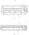
FIG. 2 is a schematic structural view of an embodiment of the air conditioning indoor unit of the present application. -
FIG. 3 is a cross-sectional view of the air conditioning indoor unit ofFIG. 2 along the III-III surface. -
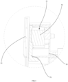
FIG. 4 is a partial enlarged view of portion A ofFIG. 3 . -
FIG. 5 is a cross-sectional view of the air conditioning indoor unit ofFIG. 2 along the V-V surface. -
FIG. 6 is a partial enlarged view of portion B ofFIG. 5 . -
FIG. 7 is a schematic structural view of another embodiment of the air conditioning indoor unit of the present application. -
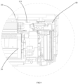
FIG. 8 is a cross-sectional view of the air conditioning indoor unit ofFIG. 7 along the VIII-VIII surface. -
FIG. 9 is a partial enlarged view of portion C ofFIG. 8 . - Description of reference numbers:
grade name grade name 100 Air conditioning indoor unit 31 Accommodating slot 10 Frame 40 Electric control box 11 Accommodating cavity 50 Driving device 13 Guide plate 60 Heat exchanger 131 Connecting portion 70 Sealing member 133 Guide portion 80 Reinforcing member 135 Crease 81 First reinforcing rib 20 Outlet 83 Second reinforcing rib 30 Chassis 90 Connecting wire - The realization of the purpose, functional features, and advantages of the present invention will be further described with reference to the accompanying drawings in conjunction with the embodiments.
- It should be noted that all directional indications (such as up, down, left, right, front, back, etc.) in the embodiments of the present application are only set to explain the relative positional relationship, movement situation, etc. between components under a specific posture (as shown in the drawings). If the specific posture is changed, the directional indications are changed accordingly.
- In the present application, unless otherwise expressly specified and qualified, the terms "connected", "fixed", and the like. should be understood in a broad sense. For example, "fixed" can be a fixed connection, a detachable connection, or be integrated into one; it can be mechanically connected or electrically connected; it can be directly connected or indirectly connected through an intermediate medium, it can be the internal communication of two elements or the interaction relationship between two elements, unless otherwise clearly defined. For those of ordinary skilled in the art, the specific meaning of the above-mentioned terms in the present application can be understood according to specific circumstances.
- In addition, the description in the present application related to "first", "second", etc. is for descriptive purposes only and cannot be understood as indicating or implying the relative importance thereof or implying the number of technical features indicated. Therefore, the features defined with "first" or "second" can explicitly or implicitly include at least one of the features. In addition, the technical solutions of various embodiments can be combined with each other, but it must be based on the realization of ordinary skills in the field. When the combination of technical solutions is contradictory or impossible, it should be considered that the combination of such technical solutions does not exist and is not within the scope of the present application.
- The present invention as defined in claim 1 provides an air conditioning
indoor unit 100. - According to
FIG. 1 to FIG. 4 , in the embodiments of the present application, the air conditioningindoor unit 100 includes: - a
frame 10 with anaccommodating cavity 11; - a
chassis 30, where theframe 10 is arranged on thechassis 30, and thechassis 30 is located in theaccommodating cavity 11, thechassis 30 and theframe 10 cooperate to form anoutlet 20 communicating with theaccommodating cavity 11, thechassis 30 is provided with anaccommodating slot 31, theaccommodating slot 31 is arranged adjacent to theoutlet 20, and theaccommodating slot 31 contains adriving device 50; and - a sealing
member 70 configured to seal theaccommodating slot 31. - Specifically, the
frame 10 mainly plays a supporting role, theframe 10 is usually made of lightweight materials such as plastic. The air conditioningindoor unit 100 may further include aheat exchanger 60 and a fan (not shown) located in theaccommodating cavity 11. The fan is arranged on thechassis 30, theheat exchanger 60 may be arranged around the fan, and an outlet end of the fan may be in communication with theoutlet 20. Thedriving device 50 can be configured to drive the fan or an air deflector to rotate. Since thedriving device 50 is disposed adjacent to theoutlet 20, the air conditioningindoor unit 100 further includes the air deflector (not shown), the air deflector is rotatably disposed at theoutlet 20, and thedriving device 50 is configured to drive the air deflector to rotate. - The
accommodating slot 31 can be arranged at any position of thechassis 30 close to theoutlet 20. In order to reduce the cross-sectional size of the air conditioningindoor unit 100 of the air conditioner and increase the radial size of the air conditioningindoor unit 100, theaccommodating slot 31 can be provided at an end of thechassis 30. An orientation of an opening of theaccommodating slot 31 can be parallel to an orientation of theoutlet 20 or the orientation of the opening of theaccommodating slot 31 and the orientation of theoutlet 20 can form an included angle. The sealingmember 70 seals theaccommodating slot 31, there is a gap or no gap between the sealingmember 70 and an inner wall of theaccommodating cavity 11, as long as the sealingmember 70 seals theaccommodating slot 31, all those solutions are within the claimed scope of the present application. The sealingmember 70 can be plastic or rubber, has elasticity and has a good sealing effect. - The air conditioning
indoor unit 100 of the present invention includes aframe 10, achassis 30 and a sealingmember 70, theframe 10 has anaccommodating cavity 11, theframe 10 is arranged on thechassis 30, thechassis 30 is located in theaccommodating cavity 11, thechassis 30 and theframe 10 cooperate to form anoutlet 20 communicating with theaccommodating cavity 11, an end of thechassis 30 close to theframe 10 is provided with anaccommodating slot 31, theaccommodating slot 31 contains a drivingdevice 50, and theaccommodating slot 31 is sealed by a sealingmember 70, as such, hot air or cold air blown from theoutlet 20 is prevented from being poured into theaccommodating slot 31 to generate condensation on the drivingdevice 50, so as to ensure the normal use of the drivingdevice 50 and high safety performance. - Preferably, in order to facilitate the replacement of the sealing
member 70, the sealingmember 70 is detachably connected to a slot wall of theaccommodating slot 31. The detachable connection can be a screw connection or a buckle connection. - According to
FIG. 4 , in an embodiment, the sealingmember 70 is in interference fit with the slot wall of theaccommodating slot 31, which can save an installation cost. An interference fit amount is between 0.5mm and 3mm, and the sealing performance is good. The shape of the sealingmember 70 matches a shape of the opening of theaccommodating slot 31. In this embodiment, theaccommodating slot 31 is elliptical, and the sealingmember 70 is accordingly elliptical. In other embodiments, theaccommodating slot 31 may have a circular or a square shape, which is not limited here. - In an embodiment, in order to improve the stability of the connection between the sealing
member 70 and theaccommodating slot 31, to prevent a size of the gap between the sealingmember 70 and the inner wall of theaccommodating slot 31 from increasing, resulting in the occurrence of a moisture unqualified phenomenon of the drivingdevice 50, a side of the sealingmember 70 away from the drivingdevice 50 abuts against an inner wall of theaccommodating cavity 11. The sealingmember 70 is thus not easily released from theaccommodating slot 31. - Further, in order to further improve the stability of the connection between the sealing
member 70 and theaccommodating slot 31, the surface of theframe 10 facing away from the sealingmember 70 may be provided with a reinforcingmember 80 to increase strength and rigidity of theframe 10. - According to
FIG. 1 , the reinforcingmember 80 may include a first reinforcingrib 81 and a second reinforcingrib 83, and the first reinforcingrib 81 intersects with the second reinforcingrib 83. There may be a plurality of first reinforcingribs 81, and the plurality of first reinforcingribs 81 are long strips, spaced from each other and parallel to each other. There may be a plurality of second reinforcingribs 83, and the plurality of second reinforcingribs 83 are long strips, spaced from each other and parallel to each other. Each of the first reinforcingribs 81 intersects with a second reinforcingribs 83, which can greatly improve the overall strength of the reinforcingmember 80. - According to
FIG. 5 to FIG. 9 , the air conditioningindoor unit 100 further includes anelectric control box 40 arranged on thechassis 30, theframe 10 is provided with a display panel (not shown), and the display panel and theelectric control box 40 are electrically connected through a connectingwire 90. - The air conditioning
indoor unit 100 may further include aheat exchanger 60 arranged in theaccommodating cavity 11, theheat exchanger 60 may be arranged at intervals from thechassis 30, an inner wall of theaccommodating cavity 11 may be provided with aguide plate 13 arranged adjacent to theelectric control box 40, and theguide plate 13 may be arranged at intervals from theheat exchanger 60. The connectingwire 90 may be arranged on a side of theguide plate 13 facing away from theheat exchanger 60. - In this embodiment, the display panel is mainly configured to display a working state of the air conditioning
indoor unit 100, and is electrically connected to theelectric control box 40 through the connectingwire 90. In order to prevent the connectingwire 90 from contacting theheat exchanger 60, causing condensed water is generated on an outer surface of the connectingwire 90, and potential safety hazards exist, aguide plate 13 is provided on the inner wall of theaccommodating cavity 11. Theguide plate 13 is arranged at intervals from theheat exchanger 60 and a gap lays between the two, the connectingwire 90 is provided on the side of theguide plate 13 facing away from theheat exchanger 60, so that the connectingwire 90 can be prevented from directly contacting theheat exchanger 60. - In order to adapt to different types of
electric control boxes 40, theguide plate 13 needs to be arranged in an easy-to-be disassembled structure. Specifically, theguide plate 13 may include a connectingportion 131 and aguide portion 133, wherein the connectingportion 131 is arranged adjacent to the display panel, and theguide portion 133 is arranged adjacent to theelectric control box 40. Acrease 135 is arranged at a connection between the connectingportion 131 and theguide portion 133. - According to
FIG. 5 andFIG. 6 , a size of theelectric control box 40 is relatively small, so that a distance between theguide plate 13 and theelectric control box 40 is relatively long. In order to avoid contact between the connectingwire 90 and theheat exchanger 60, theguide portion 133 may be inclined, the connectingwire 90 can be connected with theelectric control box 40 by theguide portion 133, and the outer surface of the connectingwire 90 is not prone to condensed water, and the safety is high. - In another embodiment, according to
FIG. 7 to FIG. 9 , theelectric control box 40 is relatively large in size, and a distance between theguide plate 13 and theelectric control box 40 is very short. In order to prevent theguide plate 13 from interfering with theelectric control box 40, theguide portion 133 may be broken through thecrease 135, thecrease 135 is a V-shaped structure, and a bottom end of the V-shaped has the weakest strength, which is easy to be broken and easy to installelectric control box 40. - The present invention further provides an air conditioner, which includes an air conditioning
indoor unit 100 as defined in the claims 1-7 and an air conditioningoutdoor unit 100 connected to the air conditioning indoor unit through a refrigerant pipe.
Claims (8)
- An air conditioning indoor unit (100), comprising:a frame (10) with an accommodating cavity (11);a chassis (30), wherein the frame (10) is provided on the chassis (30), and the chassis (30) is located in the accommodating cavity (11), the chassis (30) and the frame (10) cooperate to form an outlet (20) communicating with the accommodating cavity (11), and a lower end of the chassis (30) is provided with an accommodating slot (31) adjacent to the outlet (20), and the accommodating slot (31) accommodates a driving device (50);a sealing member (70) configured to seal the accommodating slot (31);wherein the air conditioning indoor unit (100) further comprises an air deflector, the air deflector is rotatably disposed at the outlet (20) and the driving device (50) is configured to drive the air deflector to rotate;wherein a side of the sealing member (70) away from the driving device (50) is abutted against an inner wall of the accommodating cavity (11); andwherein an opening of the accommodating slot (31) faces towards a side of the frame (10) away from the outlet (20), and the sealing member (70) is located between the accommodating cavity (11) and the frame (10) to seal the opening of the accommodating slot (31).
- The air conditioning indoor unit (100) according to claim 1, wherein the sealing member (70) is detachably connected to a slot wall of the accommodating slot (31).
- The air conditioning indoor unit (100) according to claim 2, wherein the sealing member (70) is in interference fit with the slot wall of the accommodating slot (31), and a shape of the sealing member (70) is matched with a shape of the opening of the accommodating slot (31).
- The air conditioning indoor unit (100) according to claim 1, wherein a reinforcing member (80) is provided on a surface of the frame (10) facing away from the sealing member (70).
- The air conditioning indoor unit (100) according to claim 1, wherein the reinforcing member (80) comprises a first reinforcing rib (81) and a second reinforcing rib (83), and the first reinforcing rib (81) intersects with the second reinforcing rib (83).
- The air conditioning indoor unit (100) according to any one of claims 1 to 5, wherein the air conditioning indoor unit (100) further comprises an electric control box (40) arranged on the chassis (30), the frame (10) is provided with a display panel, and the display panel and the electric control box (40) are electrically connected through a connecting wire (90);
the air conditioning indoor unit (100) further comprises a heat exchanger (60) arranged in the accommodating cavity (11), the heat exchanger (60) is spaced from the chassis (30), an inner wall of the accommodating cavity (11) is provided with a guide plate (13) adjacent to the electric control box (40), the guide plate (13) is arranged at intervals from the heat exchanger (60), and the connecting wire (90) is arranged on a side of the guide plate (13) facing away from the heat exchanger (60). - The air conditioning indoor unit (100) according to claim 6, wherein the guide plate (13) comprises a connecting portion (131) and a guide portion (133), the connecting portion (131) is disposed adjacent to the display panel, the guide portion (133) is disposed adjacent to the electric control box (40), and a crease (135) is disposed at a connection between the connecting portion (131) and the guide portion (133).
- An air conditioner, comprising an air conditioning outdoor unit and the air conditioning indoor unit (100) according to any one of claims 1 to 7, wherein the air conditioning outdoor unit is connected to the air conditioning indoor unit (100) through a refrigerant pipe.
Applications Claiming Priority (2)
| Application Number | Priority Date | Filing Date | Title |
|---|---|---|---|
| CN201922132171.0U CN211177077U (en) | 2019-11-30 | 2019-11-30 | Air conditioner indoor unit and air conditioner |
| PCT/CN2020/081184 WO2021103359A1 (en) | 2019-11-30 | 2020-03-25 | Air conditioner indoor unit and air conditioner |
Publications (4)
| Publication Number | Publication Date |
|---|---|
| EP4067774A1 EP4067774A1 (en) | 2022-10-05 |
| EP4067774A4 EP4067774A4 (en) | 2023-01-04 |
| EP4067774C0 EP4067774C0 (en) | 2024-12-04 |
| EP4067774B1 true EP4067774B1 (en) | 2024-12-04 |
Family
ID=71825049
Family Applications (1)
| Application Number | Title | Priority Date | Filing Date |
|---|---|---|---|
| EP20893884.5A Active EP4067774B1 (en) | 2019-11-30 | 2020-03-25 | Air conditioner indoor unit and air conditioner |
Country Status (4)
| Country | Link |
|---|---|
| US (1) | US12123613B2 (en) |
| EP (1) | EP4067774B1 (en) |
| CN (1) | CN211177077U (en) |
| WO (1) | WO2021103359A1 (en) |
Families Citing this family (2)
| Publication number | Priority date | Publication date | Assignee | Title |
|---|---|---|---|---|
| CN114060916A (en) * | 2020-08-05 | 2022-02-18 | 广东美的制冷设备有限公司 | Air conditioner indoor unit and air conditioner |
| CN114576705B (en) * | 2020-11-30 | 2025-02-28 | 宁波奥克斯电气有限公司 | Air conditioning cabinet and air conditioner having the same |
Family Cites Families (14)
| Publication number | Priority date | Publication date | Assignee | Title |
|---|---|---|---|---|
| JPH09112944A (en) * | 1995-10-17 | 1997-05-02 | Matsushita Electric Ind Co Ltd | Air conditioner motor mounting device |
| KR100514914B1 (en) * | 2003-12-16 | 2005-09-14 | 삼성전자주식회사 | Air Conditioner |
| KR101666222B1 (en) * | 2009-09-10 | 2016-10-13 | 엘지전자 주식회사 | Indoor unit of air conditioner |
| CN202350268U (en) * | 2011-12-22 | 2012-07-25 | 珠海格力电器股份有限公司 | Air conditioner |
| JP6532658B2 (en) * | 2014-08-01 | 2019-06-19 | 三菱重工サーマルシステムズ株式会社 | Indoor unit and air conditioner |
| KR101742502B1 (en) * | 2015-12-31 | 2017-06-01 | 엘지전자 주식회사 | An air conditioner |
| WO2018137438A1 (en) * | 2017-01-25 | 2018-08-02 | 珠海格力电器股份有限公司 | Air conditioner indoor unit |
| CN107101278B (en) * | 2017-06-21 | 2019-06-04 | 美的集团股份有限公司 | Air conditioner indoor unit and air conditioner |
| CN108006838B (en) * | 2018-01-31 | 2024-05-28 | 广东美的制冷设备有限公司 | Housing assembly of air conditioner indoor unit and air conditioner indoor unit |
| CN208253752U (en) * | 2018-06-01 | 2018-12-18 | 广东美的制冷设备有限公司 | Air conditioner wall-mounted machine and air conditioner |
| CN209042555U (en) * | 2018-11-08 | 2019-06-28 | 广东美的制冷设备有限公司 | Air conditioner indoor unit and air conditioner |
| CN109708202A (en) * | 2019-02-25 | 2019-05-03 | 广东美的制冷设备有限公司 | Air conditioner indoor unit and its switch door component |
| CN209672480U (en) * | 2019-03-03 | 2019-11-22 | 广东美的制冷设备有限公司 | Air conditioner indoor unit and air conditioner |
| CN109916064A (en) * | 2019-03-19 | 2019-06-21 | 武汉宏海科技股份有限公司 | A kind of assembling structure of air conditioner indoor unit electric-controlled box |
-
2019
- 2019-11-30 CN CN201922132171.0U patent/CN211177077U/en active Active
-
2020
- 2020-03-25 WO PCT/CN2020/081184 patent/WO2021103359A1/en not_active Ceased
- 2020-03-25 EP EP20893884.5A patent/EP4067774B1/en active Active
-
2022
- 2022-05-19 US US17/748,319 patent/US12123613B2/en active Active
Also Published As
| Publication number | Publication date |
|---|---|
| EP4067774C0 (en) | 2024-12-04 |
| US20220275965A1 (en) | 2022-09-01 |
| EP4067774A4 (en) | 2023-01-04 |
| US12123613B2 (en) | 2024-10-22 |
| WO2021103359A1 (en) | 2021-06-03 |
| CN211177077U (en) | 2020-08-04 |
| EP4067774A1 (en) | 2022-10-05 |
Similar Documents
| Publication | Publication Date | Title |
|---|---|---|
| CN108731108B (en) | Air conditioner | |
| CN108278675B (en) | Cabinet air conditioner and control method thereof | |
| CN111623429A (en) | Air conditioner | |
| US12123613B2 (en) | Air-conditioning indoor unit and air conditioner | |
| CN106225083A (en) | The air-out control method of cabinet air-conditioner and cabinet air-conditioner | |
| CN205717525U (en) | Indoor apparatus of air conditioner and air-conditioner | |
| CN210601985U (en) | Humidification Modules, Air Conditioning Indoor Units and Air Conditioners | |
| CN214307374U (en) | Middle partition plate assembly, outdoor unit, air conditioner and water heater | |
| CN106403060A (en) | Window type air conditioner | |
| CN211177072U (en) | Air conditioner indoor unit and air conditioner | |
| CN211739311U (en) | Window type air conditioner partition plate and window type air conditioner | |
| CN109724155B (en) | Air duct component and air conditioner indoor unit having the same | |
| JP6097931B2 (en) | Heat exchange ventilator | |
| CN216522295U (en) | Panel components and air conditioning indoor unit | |
| CN219063703U (en) | Air conditioner indoor unit and air conditioner | |
| CN208332618U (en) | A kind of central air-conditioning air deflection assemblies | |
| CN223216431U (en) | Fresh air module and air conditioner | |
| CN206073285U (en) | Cabinet air-conditioner | |
| CN105953403A (en) | Mounting rack and cross-flow wind wheel assembly | |
| CN211575255U (en) | Air conditioner indoor unit and air conditioner | |
| CN221122360U (en) | Air duct structure and bathroom heater | |
| CN219589070U (en) | Air conditioner outdoor unit | |
| CN221424961U (en) | Air guide structure and cabinet air conditioner | |
| KR200198162Y1 (en) | A mounting structure of outdoor unit for seperated type air conditioner | |
| CN219389922U (en) | Air conditioner outdoor unit |
Legal Events
| Date | Code | Title | Description |
|---|---|---|---|
| STAA | Information on the status of an ep patent application or granted ep patent |
Free format text: STATUS: THE INTERNATIONAL PUBLICATION HAS BEEN MADE |
|
| PUAI | Public reference made under article 153(3) epc to a published international application that has entered the european phase |
Free format text: ORIGINAL CODE: 0009012 |
|
| STAA | Information on the status of an ep patent application or granted ep patent |
Free format text: STATUS: REQUEST FOR EXAMINATION WAS MADE |
|
| 17P | Request for examination filed |
Effective date: 20220627 |
|
| AK | Designated contracting states |
Kind code of ref document: A1 Designated state(s): AL AT BE BG CH CY CZ DE DK EE ES FI FR GB GR HR HU IE IS IT LI LT LU LV MC MK MT NL NO PL PT RO RS SE SI SK SM TR |
|
| A4 | Supplementary search report drawn up and despatched |
Effective date: 20221205 |
|
| RIC1 | Information provided on ipc code assigned before grant |
Ipc: F24F 1/0011 20190101ALI20221129BHEP Ipc: F24F 11/89 20180101ALI20221129BHEP Ipc: F24F 13/08 20060101ALI20221129BHEP Ipc: F24F 13/20 20060101AFI20221129BHEP |
|
| DAV | Request for validation of the european patent (deleted) | ||
| DAX | Request for extension of the european patent (deleted) | ||
| STAA | Information on the status of an ep patent application or granted ep patent |
Free format text: STATUS: EXAMINATION IS IN PROGRESS |
|
| 17Q | First examination report despatched |
Effective date: 20231025 |
|
| GRAP | Despatch of communication of intention to grant a patent |
Free format text: ORIGINAL CODE: EPIDOSNIGR1 |
|
| STAA | Information on the status of an ep patent application or granted ep patent |
Free format text: STATUS: GRANT OF PATENT IS INTENDED |
|
| RIC1 | Information provided on ipc code assigned before grant |
Ipc: F24F 1/0011 20190101ALI20240610BHEP Ipc: F24F 11/89 20180101ALI20240610BHEP Ipc: F24F 13/08 20060101ALI20240610BHEP Ipc: F24F 13/20 20060101AFI20240610BHEP |
|
| INTG | Intention to grant announced |
Effective date: 20240710 |
|
| GRAS | Grant fee paid |
Free format text: ORIGINAL CODE: EPIDOSNIGR3 |
|
| GRAA | (expected) grant |
Free format text: ORIGINAL CODE: 0009210 |
|
| STAA | Information on the status of an ep patent application or granted ep patent |
Free format text: STATUS: THE PATENT HAS BEEN GRANTED |
|
| AK | Designated contracting states |
Kind code of ref document: B1 Designated state(s): AL AT BE BG CH CY CZ DE DK EE ES FI FR GB GR HR HU IE IS IT LI LT LU LV MC MK MT NL NO PL PT RO RS SE SI SK SM TR |
|
| REG | Reference to a national code |
Ref country code: CH Ref legal event code: EP |
|
| REG | Reference to a national code |
Ref country code: DE Ref legal event code: R096 Ref document number: 602020042776 Country of ref document: DE |
|
| REG | Reference to a national code |
Ref country code: IE Ref legal event code: FG4D |
|
| U01 | Request for unitary effect filed |
Effective date: 20241220 |
|
| U07 | Unitary effect registered |
Designated state(s): AT BE BG DE DK EE FI FR IT LT LU LV MT NL PT RO SE SI Effective date: 20250113 |
|
| PG25 | Lapsed in a contracting state [announced via postgrant information from national office to epo] |
Ref country code: HR Free format text: LAPSE BECAUSE OF FAILURE TO SUBMIT A TRANSLATION OF THE DESCRIPTION OR TO PAY THE FEE WITHIN THE PRESCRIBED TIME-LIMIT Effective date: 20241204 |
|
| PG25 | Lapsed in a contracting state [announced via postgrant information from national office to epo] |
Ref country code: ES Free format text: LAPSE BECAUSE OF FAILURE TO SUBMIT A TRANSLATION OF THE DESCRIPTION OR TO PAY THE FEE WITHIN THE PRESCRIBED TIME-LIMIT Effective date: 20241204 |
|
| PG25 | Lapsed in a contracting state [announced via postgrant information from national office to epo] |
Ref country code: NO Free format text: LAPSE BECAUSE OF FAILURE TO SUBMIT A TRANSLATION OF THE DESCRIPTION OR TO PAY THE FEE WITHIN THE PRESCRIBED TIME-LIMIT Effective date: 20250304 |
|
| U20 | Renewal fee for the european patent with unitary effect paid |
Year of fee payment: 6 Effective date: 20250318 |
|
| PG25 | Lapsed in a contracting state [announced via postgrant information from national office to epo] |
Ref country code: GR Free format text: LAPSE BECAUSE OF FAILURE TO SUBMIT A TRANSLATION OF THE DESCRIPTION OR TO PAY THE FEE WITHIN THE PRESCRIBED TIME-LIMIT Effective date: 20250305 |
|
| PG25 | Lapsed in a contracting state [announced via postgrant information from national office to epo] |
Ref country code: RS Free format text: LAPSE BECAUSE OF FAILURE TO SUBMIT A TRANSLATION OF THE DESCRIPTION OR TO PAY THE FEE WITHIN THE PRESCRIBED TIME-LIMIT Effective date: 20250304 |
|
| PG25 | Lapsed in a contracting state [announced via postgrant information from national office to epo] |
Ref country code: SM Free format text: LAPSE BECAUSE OF FAILURE TO SUBMIT A TRANSLATION OF THE DESCRIPTION OR TO PAY THE FEE WITHIN THE PRESCRIBED TIME-LIMIT Effective date: 20241204 |
|
| PG25 | Lapsed in a contracting state [announced via postgrant information from national office to epo] |
Ref country code: PL Free format text: LAPSE BECAUSE OF FAILURE TO SUBMIT A TRANSLATION OF THE DESCRIPTION OR TO PAY THE FEE WITHIN THE PRESCRIBED TIME-LIMIT Effective date: 20241204 |
|
| PG25 | Lapsed in a contracting state [announced via postgrant information from national office to epo] |
Ref country code: IS Free format text: LAPSE BECAUSE OF FAILURE TO SUBMIT A TRANSLATION OF THE DESCRIPTION OR TO PAY THE FEE WITHIN THE PRESCRIBED TIME-LIMIT Effective date: 20250404 |
|
| PG25 | Lapsed in a contracting state [announced via postgrant information from national office to epo] |
Ref country code: SK Free format text: LAPSE BECAUSE OF FAILURE TO SUBMIT A TRANSLATION OF THE DESCRIPTION OR TO PAY THE FEE WITHIN THE PRESCRIBED TIME-LIMIT Effective date: 20241204 |
|
| PG25 | Lapsed in a contracting state [announced via postgrant information from national office to epo] |
Ref country code: CZ Free format text: LAPSE BECAUSE OF FAILURE TO SUBMIT A TRANSLATION OF THE DESCRIPTION OR TO PAY THE FEE WITHIN THE PRESCRIBED TIME-LIMIT Effective date: 20241204 |
|
| PLBE | No opposition filed within time limit |
Free format text: ORIGINAL CODE: 0009261 |
|
| STAA | Information on the status of an ep patent application or granted ep patent |
Free format text: STATUS: NO OPPOSITION FILED WITHIN TIME LIMIT |
|
| PG25 | Lapsed in a contracting state [announced via postgrant information from national office to epo] |
Ref country code: MC Free format text: LAPSE BECAUSE OF FAILURE TO SUBMIT A TRANSLATION OF THE DESCRIPTION OR TO PAY THE FEE WITHIN THE PRESCRIBED TIME-LIMIT Effective date: 20241204 |
|
| REG | Reference to a national code |
Ref country code: CH Ref legal event code: L10 Free format text: ST27 STATUS EVENT CODE: U-0-0-L10-L00 (AS PROVIDED BY THE NATIONAL OFFICE) Effective date: 20251015 |
|
| REG | Reference to a national code |
Ref country code: CH Ref legal event code: H13 Free format text: ST27 STATUS EVENT CODE: U-0-0-H10-H13 (AS PROVIDED BY THE NATIONAL OFFICE) Effective date: 20251023 |
|
| 26N | No opposition filed |
Effective date: 20250905 |
|
| GBPC | Gb: european patent ceased through non-payment of renewal fee |
Effective date: 20250325 |
|
| PG25 | Lapsed in a contracting state [announced via postgrant information from national office to epo] |
Ref country code: GB Free format text: LAPSE BECAUSE OF NON-PAYMENT OF DUE FEES Effective date: 20250325 |
|
| PG25 | Lapsed in a contracting state [announced via postgrant information from national office to epo] |
Ref country code: CH Free format text: LAPSE BECAUSE OF NON-PAYMENT OF DUE FEES Effective date: 20250331 |
|
| PG25 | Lapsed in a contracting state [announced via postgrant information from national office to epo] |
Ref country code: IE Free format text: LAPSE BECAUSE OF NON-PAYMENT OF DUE FEES Effective date: 20250325 |
|
| U20 | Renewal fee for the european patent with unitary effect paid |
Year of fee payment: 7 Effective date: 20260325 |