EP4067747A1 - Turbine engine fuel injector with non-circular nozzle passage - Google Patents
Turbine engine fuel injector with non-circular nozzle passage Download PDFInfo
- Publication number
- EP4067747A1 EP4067747A1 EP22166587.0A EP22166587A EP4067747A1 EP 4067747 A1 EP4067747 A1 EP 4067747A1 EP 22166587 A EP22166587 A EP 22166587A EP 4067747 A1 EP4067747 A1 EP 4067747A1
- Authority
- EP
- European Patent Office
- Prior art keywords
- nozzle
- fuel
- passage
- orifice
- centerline
- Prior art date
- Legal status (The legal status is an assumption and is not a legal conclusion. Google has not performed a legal analysis and makes no representation as to the accuracy of the status listed.)
- Granted
Links
Images





Classifications
-
- F—MECHANICAL ENGINEERING; LIGHTING; HEATING; WEAPONS; BLASTING
- F23—COMBUSTION APPARATUS; COMBUSTION PROCESSES
- F23R—GENERATING COMBUSTION PRODUCTS OF HIGH PRESSURE OR HIGH VELOCITY, e.g. GAS-TURBINE COMBUSTION CHAMBERS
- F23R3/00—Continuous combustion chambers using liquid or gaseous fuel
- F23R3/28—Continuous combustion chambers using liquid or gaseous fuel characterised by the fuel supply
-
- B—PERFORMING OPERATIONS; TRANSPORTING
- B33—ADDITIVE MANUFACTURING TECHNOLOGY
- B33Y—ADDITIVE MANUFACTURING, i.e. MANUFACTURING OF THREE-DIMENSIONAL [3D] OBJECTS BY ADDITIVE DEPOSITION, ADDITIVE AGGLOMERATION OR ADDITIVE LAYERING, e.g. BY 3D PRINTING, STEREOLITHOGRAPHY OR SELECTIVE LASER SINTERING
- B33Y80/00—Products made by additive manufacturing
-
- F—MECHANICAL ENGINEERING; LIGHTING; HEATING; WEAPONS; BLASTING
- F23—COMBUSTION APPARATUS; COMBUSTION PROCESSES
- F23R—GENERATING COMBUSTION PRODUCTS OF HIGH PRESSURE OR HIGH VELOCITY, e.g. GAS-TURBINE COMBUSTION CHAMBERS
- F23R3/00—Continuous combustion chambers using liquid or gaseous fuel
- F23R3/28—Continuous combustion chambers using liquid or gaseous fuel characterised by the fuel supply
- F23R3/286—Continuous combustion chambers using liquid or gaseous fuel characterised by the fuel supply having fuel-air premixing devices
-
- F—MECHANICAL ENGINEERING; LIGHTING; HEATING; WEAPONS; BLASTING
- F23—COMBUSTION APPARATUS; COMBUSTION PROCESSES
- F23R—GENERATING COMBUSTION PRODUCTS OF HIGH PRESSURE OR HIGH VELOCITY, e.g. GAS-TURBINE COMBUSTION CHAMBERS
- F23R3/00—Continuous combustion chambers using liquid or gaseous fuel
- F23R3/42—Continuous combustion chambers using liquid or gaseous fuel characterised by the arrangement or form of the flame tubes or combustion chambers
- F23R3/54—Reverse-flow combustion chambers
-
- B—PERFORMING OPERATIONS; TRANSPORTING
- B33—ADDITIVE MANUFACTURING TECHNOLOGY
- B33Y—ADDITIVE MANUFACTURING, i.e. MANUFACTURING OF THREE-DIMENSIONAL [3D] OBJECTS BY ADDITIVE DEPOSITION, ADDITIVE AGGLOMERATION OR ADDITIVE LAYERING, e.g. BY 3D PRINTING, STEREOLITHOGRAPHY OR SELECTIVE LASER SINTERING
- B33Y10/00—Processes of additive manufacturing
-
- F—MECHANICAL ENGINEERING; LIGHTING; HEATING; WEAPONS; BLASTING
- F05—INDEXING SCHEMES RELATING TO ENGINES OR PUMPS IN VARIOUS SUBCLASSES OF CLASSES F01-F04
- F05D—INDEXING SCHEME FOR ASPECTS RELATING TO NON-POSITIVE-DISPLACEMENT MACHINES OR ENGINES, GAS-TURBINES OR JET-PROPULSION PLANTS
- F05D2230/00—Manufacture
- F05D2230/30—Manufacture with deposition of material
- F05D2230/31—Layer deposition
-
- F—MECHANICAL ENGINEERING; LIGHTING; HEATING; WEAPONS; BLASTING
- F05—INDEXING SCHEMES RELATING TO ENGINES OR PUMPS IN VARIOUS SUBCLASSES OF CLASSES F01-F04
- F05D—INDEXING SCHEME FOR ASPECTS RELATING TO NON-POSITIVE-DISPLACEMENT MACHINES OR ENGINES, GAS-TURBINES OR JET-PROPULSION PLANTS
- F05D2240/00—Components
- F05D2240/35—Combustors or associated equipment
- F05D2240/36—Fuel vaporizer
Definitions
- This invention relates generally to a turbine engine and, more particularly, to a fuel injector assembly for the turbine engine.
- a combustor section in a modern turbine engine includes one or more fuel injectors.
- Each fuel injector is operable to inject fuel for combustion within a combustion chamber.
- Various types and configurations of fuel injectors are known in the art. While these known fuel injectors have various benefits, there is still room in the art for improvement. There is a need in the art, for example, for a fuel injector with reduced manufacturing costs, that facilitates reduced assembly time as well as provides precision fuel injection.
- an apparatus for a turbine engine.
- This turbine engine apparatus includes a fuel nozzle.
- the fuel nozzle includes a nozzle passage and a nozzle orifice.
- the nozzle passage extends longitudinally along a centerline within the fuel nozzle to the nozzle orifice.
- the nozzle passage has a solid polygonal cross-sectional geometry at the nozzle orifice.
- a method of manufacturing is provided.
- a fuel nozzle is additively manufactured.
- the additively manufacturing provides the fuel nozzle with a nozzle passage and a nozzle orifice.
- the nozzle passage extends longitudinally along a centerline within the fuel nozzle to the nozzle orifice. At least a first portion of the nozzle passage tapers inward towards the centerline as the nozzle passage extends longitudinally along the centerline towards the nozzle orifice.
- a slope of the taper has a rise to run ratio of less than 0.6.
- a fuel nozzle is additively manufactured.
- the additively manufacturing provides the fuel nozzle with a nozzle passage and a nozzle orifice.
- the nozzle passage extends longitudinally along a centerline within the fuel nozzle to the nozzle orifice.
- the nozzle orifice has a lateral width less than 0.0223 inches (0.0566 centimeters).
- the nozzle passage may have a non-annular, non-circular cross-sectional geometry at the nozzle orifice.
- the nozzle passage may have a square or diamond shaped cross-sectional geometry at the nozzle orifice.
- the solid polygonal cross-sectional geometry may have a diamond shape.
- the solid polygonal cross-sectional geometry may have a square shape.
- At least a first portion the nozzle passage may taper inward towards the centerline as the nozzle passage extends longitudinally along the centerline towards the nozzle orifice.
- a slope of the taper may have a rise to run ratio of less than 0.6, 0.5 or 0.4.
- At least a first portion of an exterior of the fuel nozzle may have a constant lateral width as the exterior of the fuel nozzle extends longitudinally along the centerline towards the nozzle orifice.
- the first portion of the exterior of the fuel nozzle may longitudinally overlap the first portion the nozzle passage along the centerline.
- a second portion of the nozzle passage may be longitudinally between the first portion of the nozzle passage and the nozzle orifice along the centerline.
- the second portion of the nozzle passage may have a constant lateral width longitudinally along the centerline.
- the first portion of the nozzle passage and the second portion of the nozzle passage may each have the solid polygonal cross-sectional geometry.
- the first portion of the nozzle passage may be longitudinally between the nozzle orifice and a second portion of the nozzle passage along the centerline.
- the second portion of the nozzle passage may have a constant lateral width longitudinally along the centerline.
- the first portion of the nozzle passage may have the solid polygonal cross-sectional geometry.
- the second portion of the nozzle passage may have a second cross-sectional geometry that is different than the solid polygonal cross-sectional geometry.
- the solid polygonal cross-sectional geometry may extend along a longitudinal length of the nozzle passage.
- the nozzle orifice may have a lateral width less than 0.0223 inches (0.0566 centimeters).
- the fuel nozzle may have a tubular sidewall forming the nozzle passage.
- the tubular sidewall may have a minimum lateral width that is less than 0.01 inches (0.0254 centimeters).
- the turbine engine apparatus may also include a fuel conduit fluidly coupled with the fuel nozzle.
- the fuel nozzle may be configured to receive fuel from the fuel conduit within the nozzle passage.
- the fuel nozzle may also be configured to direct the fuel out of the nozzle passage through the nozzle orifice.
- the turbine engine apparatus may also include an air tube including an air passage.
- the fuel nozzle may project into the air passage.
- the fuel nozzle may be configured to direct fuel out of the nozzle passage through the nozzle orifice into the air passage.
- the turbine engine apparatus may also include a combustor wall.
- the combustor wall may at least partially form a combustion chamber.
- the air tube may be connected to the combustor wall and may project into the combustion chamber.
- the present invention may include any one or more of the individual features disclosed above and/or below alone or in any combination thereof.
- FIG. 1 illustrates a portion of an apparatus 20 for a turbine engine.
- This turbine engine apparatus 20 is configured as, or otherwise includes, a fuel injector assembly 22 for a combustor section of the turbine engine.
- the turbine engine apparatus 20 includes a fuel conduit 24 and a fuel nozzle 26; e.g., a single and/or central orifice fuel nozzle.
- the turbine engine apparatus 20 of FIG. 1 may also include an apparatus base 28, which apparatus base 28 may provide a structural support for the fuel conduit 24 and/or the fuel nozzle 26.
- the apparatus base 28 may be configured as any part of the turbine engine within the combustor section that is proximate the fuel injector assembly 22.
- the apparatus base 28 of FIG. 1 may be configured as a turbine engine case such as, but not limited to, a combustor section case, a diffuser case and/or a combustor wall.
- the fuel conduit 24 is configured as, or may be part of, a fuel supply for the fuel nozzle 26.
- the fuel conduit 24, for example, may be or may be part of a fuel supply tube, a fuel inlet manifold and/or a fuel distribution manifold.
- the fuel conduit 24 is arranged at and/or is connected to a first side 30 (e.g., an exterior and/or outer side) of the apparatus base 28.
- the fuel conduit 24 is configured with an internal fuel supply passage 32 formed by an internal aperture (e.g., a bore, channel, etc.) within the fuel conduit 24.
- the supply passage 32 and the associated aperture extend within and/or through the fuel conduit 24 along a (e.g., curved and/or straight) centerline 34 of the supply passage 32, which may also be a centerline of the fuel conduit 24.
- the fuel nozzle 26 is configured to receive (e.g., liquid) fuel from the fuel conduit 24, and inject that received fuel into a plenum 36 (e.g., a fluid passage such as an air passage) at a distal end 38 (e.g., tip) of the fuel nozzle 26.
- a plenum 36 e.g., a fluid passage such as an air passage
- the fuel nozzle 26 of FIG. 2 includes a nozzle body 40 and a nozzle passage 42; e.g., a fuel passage.
- the nozzle body 40 is arranged at and/or is connected to a second side 44 (e.g., an interior and/or inner side) of the apparatus base 28, where the base second side 44 is opposite the base first side 30.
- the nozzle body 40 of FIG. 2 includes a nozzle tube 46 and a nozzle support structure 48; e.g., a web.
- a base end of the nozzle tube 46 is connected to the apparatus base 28.
- the nozzle tube 46 projects longitudinally out from the apparatus base 28 along a (e.g., straight and/or curved) longitudinal centerline 50 of the nozzle passage 42 and/or the nozzle tube 46 to the fuel nozzle distal end 38.
- the nozzle support structure 48 is connected to and extends between the apparatus base 28 and a (e.g., upstream) side of the nozzle tube 46.
- the nozzle support structure 48 structurally ties the nozzle tube 46 to the apparatus base 28 and may thereby support the nozzle tube 46 within the plenum 36.
- the nozzle support structure 48 may form a support gusset for the nozzle tube 46.
- An internal bore of the nozzle tube 46 at least partially (or completely) forms the nozzle passage 42.
- the nozzle passage 42 extends longitudinally along the longitudinal centerline 50 within and/or through the apparatus base 28 and the nozzle tube 46 from the supply passage 32 to a downstream nozzle orifice 52 at the fuel nozzle distal end 38.
- This nozzle orifice 52 provides an outlet from the nozzle passage 42 and, more generally, the fuel nozzle 26.
- the nozzle passage 42 includes one or more different flow portions (e.g., 54 and 56) arranged longitudinally along the longitudinal centerline 50.
- the nozzle passage 42 of FIG. 3 for example, includes a (e.g., upstream) convergent portion 54 and a (e.g., downstream) throat portion 56.
- the convergent portion 54 is upstream of the throat portion 56, for example at (e.g., on, adjacent or proximate) an upstream end 58 of the nozzle passage 42.
- the convergent portion 54 of FIG. 3 is formed by one or more tapering convergent sidewall surfaces 60; see also FIG. 4 . These convergent sidewall surfaces 60 and, thus, the convergent portion 54 extend longitudinally along the longitudinal centerline 50 from the supply passage 32 to the throat portion 56, thereby defining a longitudinal length 62 of the convergent portion 54.
- a lateral width 64 (e.g., a diagonal axis) of the convergent portion 54 (e.g., continuously) decreases as the nozzle passage 42 extends longitudinally along the longitudinal centerline 50 towards the throat portion 56 / the nozzle orifice 52.
- the convergent portion lateral width 64 at the nozzle passage upstream end 58 is greater than the convergent portion lateral width 64 at the throat portion 56.
- a slope of a taper of the convergent portion 54 and its tapering convergent sidewall surfaces 60 has a rise to run ratio (Y/X; see FIG. 5 ).
- This convergent portion rise to run ratio may be equal to or less than about (e.g., +/- 1%) or exactly 0.6 (e.g., ⁇ 0.577), for example, to minimize head loss due to contraction.
- Y/X rise to run ratio
- the convergent portion 54 and its tapering convergent sidewall surfaces 60 may extend longitudinally along the longitudinal centerline 50 (the run X), the convergent portion 54 and its tapering convergent sidewall surfaces 60 may extend laterally (e.g., in a direction perpendicular to the longitudinal centerline 50) three (3) units (the rise Y).
- Such a convergent portion rise to run ratio may facilitate in the additive manufacturing of the fuel nozzle 26, for example, by minimizing layer-to-layer overhangs and/or minimizing variation in lateral sidewall thickness 66 (see FIG. 4 ) of the nozzle tube 46.
- the present disclosure is not limited to such an exemplary convergent portion rise to run ratio nor to any particular manufacturing techniques.
- the rise to run ratio may be equal to or less than 0.5, 0.4, 0.3, etc. In other embodiments, the rise to run ratio may be greater than 0.6, but less than 1 for example.
- the throat portion 56 is downstream of the convergent portion 54, for example at (e.g., on, adjacent or proximate) the fuel nozzle distal end 38. A downstream most end of the throat portion 56 may also define the nozzle orifice 52.
- the throat portion 56 of FIG. 3 is formed by one or more (e.g., non-tapered) throat sidewall surfaces 68 (see also FIG. 6 ). These throat sidewall surfaces 68 and, thus, the throat portion 56 extend longitudinally along the longitudinal centerline 50 from the convergent portion 54 to (or towards) the nozzle orifice 52 in the fuel nozzle distal end 38, thereby defining a longitudinal length 70 of the throat portion 56.
- the throat portion longitudinal length 70 may be different (e.g., less) than the convergent portion longitudinal length 62.
- the convergent portion longitudinal length 62 for example, may be more than two times (2x), five times (5x) or ten times (10x) the throat portion longitudinal length 70.
- the present disclosure is not limited to the foregoing dimensional relationship between the lengths.
- a lateral width 72 (e.g., a diagonal axis 74 as shown in FIG. 6 ) of the throat portion 56 may be about (e.g., +/- 1%) or exactly constant as the nozzle passage 42 extends longitudinally along the longitudinal centerline 50 towards the nozzle orifice 52.
- the throat portion lateral width 72 at the convergent portion 54 is equal to the throat portion lateral width 72 at the nozzle orifice 52.
- the throat portion 56 is non-tapered.
- one or more portion of the nozzle passage 42 may have a solid (e.g., non-annular) non-circular cross-sectional geometry (or other non-circular cross-sectional geometry), for example, when viewed in a plane perpendicular to the longitudinal centerline 50.
- each nozzle passage portion 54, 56 and, thus, an entirety of the nozzle passage 42 of FIGS. 3 , 4 and 6 has the (e.g., same) polygonal cross-sectional geometry.
- This polygonal cross-sectional geometry may be square shaped and/or diamond shaped as shown in FIGS. 4 and 6 .
- the present disclosure is not limited to such exemplary polygonal shapes.
- the polygonal cross-sectional geometry may have a triangular shape or any other polygonal shape.
- the polygonal cross-sectional geometry may aid in minimizing variation in as-formed surface finish (e.g., surface roughness and/or surface distortions) of the nozzle passage surfaces 60, 68, particularly where the fuel nozzle 26 is additively manufactured and/or the nozzle passage lateral width (e.g., 64, 72; see FIG. 3 ) is relatively small.
- Configuring the nozzle passage 42 with the polygonal cross-sectional geometry may thereby reduce actual (e.g., additively manufactured, as-formed) dimensional and/or geometric deviation of the nozzle passage 42 and its nozzle orifice 52 from a (e.g., design) standard as schematically shown, for example, in FIG. 7 .
- layer-to-layer distortions produced during additive manufacturing may leave a nozzle passage 800 designed to have a circular cross-sectional geometry with a relative rough and/or otherwise distorted nozzle passage surface 802.
- Such distortions may increase actual dimensional and/or geometric deviation of the circular nozzle passage 800 from its (e.g., design) standard. This increase in deviation particularly at a nozzle orifice 804 may reduce fuel metering precision through the circular nozzle orifice 804.
- a turbine engine includes multiple fuel nozzles with the circular nozzle orifice 804
- fuel metering precision of the fuel nozzle 26 can be increased. Deviation between multiple fuel nozzles 26 can also be reduced and, thus, fuel burn and/or hot streak imbalance may also be reduced.
- the fuel nozzle 26 may be designed with relatively small dimensions while still being producible via various manufacturing techniques including additive manufacturing.
- the nozzle orifice 52 of FIG. 6 is configured with a (e.g., minimum or maximum) lateral width (e.g., the lateral width 72) which may be equal to or less than about (e.g., +/- 1%) or exactly 0.0223 inches (0.0566 centimeters); e.g., ⁇ 0.019 inches (0.0483 centimeters).
- a lateral width e.g., the lateral width 72
- a tubular sidewall 76 of the nozzle tube 46 may have a (e.g., minimum, smallest) lateral thickness 78 equal to or less than about (e.g., +/- 1%) or exactly 0.010 inches (0.0254 centimeters).
- a lateral thickness 78 equal to or less than about (e.g., +/- 1%) or exactly 0.010 inches (0.0254 centimeters).
- fuel is directed into the supply passage 32 from a fuel source (not shown). At least a portion (or all) of the fuel within the supply passage 32 is directed into the nozzle passage 42. This fuel flows through the nozzle passage 42 and out of the fuel nozzle 26 through the nozzle orifice 52 and into the plenum 36.
- the fuel within the plenum 36 may be mixed with air (e.g., compressed air) for subsequent combustion.
- the nozzle passage 42 may also be configured with a flow channel portion 80.
- This flow channel portion 80 is upstream of the convergent portion 54, for example at (e.g., on, adjacent or proximate) the nozzle passage upstream end 58.
- the flow channel portion 80 of FIG. 9 is formed by at least one (e.g., non-tapering, cylindrical) flow channel sidewall surface 82.
- This flow channel sidewall surface 82 and, thus, the flow channel portion 80 extend longitudinally along the longitudinal centerline 50 from the supply passage 32 to the convergent portion 54, thereby defining a longitudinal length 84 of the flow channel portion 80.
- the flow channel portion longitudinal length 84 may be different (e.g., greater) than the convergent portion longitudinal length 62.
- the convergent portion longitudinal length 62 may be less than the flow channel portion longitudinal length 84 but greater than fifteen percent (15%) of the flow channel portion longitudinal length 84. More particularly, the convergent portion longitudinal length 62 may be between twenty-five percent (25%) and seventy-five percent (75%) of the flow channel portion longitudinal length 84.
- the present disclosure is not limited to the foregoing dimensional relationship between the lengths 62 and 84.
- the convergent portion longitudinal length 62 may be equal to or greater than the flow channel portion longitudinal length 84.
- a lateral width 86 (e.g., a diameter) of the flow channel portion 80 may be about (e.g., +/- 1%) or exactly constant as the nozzle passage 42 extends longitudinally along the longitudinal centerline 50 towards the throat portion 56 / the nozzle orifice 52.
- the flow channel portion lateral width 86 at the nozzle passage upstream end 58 is equal to the flow channel portion lateral width 86 at the convergent portion 54.
- the flow channel portion 80 is non-tapered.
- one portion of the nozzle passage 42 may have a different cross-sectional geometry than another portion of the nozzle passage 42, for example, when viewed in respective planes perpendicular to the longitudinal centerline 50.
- the throat portion 56 and at least an adjacent section of the convergent portion 54 of FIG. 9 may each be configured with the (e.g., same) solid polygonal cross-sectional geometry (see FIGS. 4 and 6 ).
- the flow channel portion 80 and at least an adjacent section of the convergent portion 54 of FIG. 9 may be configured with a different cross-sectional geometry (see FIG.
- each of the nozzle passage portions 54, 56 and 80 may be configured with the (e.g., same) solid polygonal cross-sectional geometry.
- At least a portion (or an entirety) of an exterior 88 of the fuel nozzle 26 and its nozzle tube 46 may have a constant lateral width 90 as the exterior 88 extends longitudinally along the longitudinal centerline 50, for example, from the apparatus base 28 (see FIG. 2 ) to (or towards) the fuel nozzle distal end 38 / the nozzle orifice 52.
- This at least a portion (or the entirety) of the exterior 88 may (e.g., partially or completely) longitudinally overlap any one or more of the nozzle passage portions (e.g., 54, 56 and/or 80; 80 not shown in FIG. 11 ) along the longitudinal centerline 50.
- At least a portion (or the entirety) of the exterior 88 of the fuel nozzle 26 and its nozzle tube 46 may have a variable lateral width 90'.
- the exterior 88 of FIG. 12 for example, laterally tapers inward towards the longitudinal centerline 50 as the exterior 88 extends longitudinally along the longitudinal centerline 50, for example, from the apparatus base 28 (see FIG. 2 ) to (or towards) the fuel nozzle distal end 38 / the nozzle orifice 52.
- This at least a portion (or the entirety) of the exterior 88 may (e.g., partially or completely) longitudinally overlap any one or more of the nozzle passage portions (e.g., 54, 56 and/or 80; 80 not shown in FIG. 11 ) along the longitudinal centerline 50.
- the fuel nozzle 26 may be one of a plurality of fuel nozzles 26 connected to the apparatus base 28 and fluidly coupled with the fuel conduit 24. These fuel nozzles 26 may be arranged circumferentially about a centerline / rotational axis 92 of the turbine engine in an annular array.
- the turbine engine apparatus 20 may also include one or more fuel vaporizers 94.
- Each fuel nozzle 26 is arranged with a respective one of the fuel vaporizers 94. More particularly, each fuel nozzle 26 projects into a respective one of the fuel vaporizers 94 and is arranged within a fluid passage 96 (e.g., an air passage; the plenum 36 in FIGS. 1-3 ) of the respective fuel vaporizer 94. With such an arrangement, each fuel nozzle 26 may direct at least a portion of the fuel injected into the fluid passage 96 against a (e.g., tubular) surface 98 of the respective fuel vaporizer 94. The fuel vaporizer 94 may at least partially vaporize the fuel impinging against its surface 98.
- each fuel vaporizer 94 is configured as a structure such as a flow tube 100 (e.g., a fluid tube, an air tube) for a combustor 102 in the combustor section 104.
- the combustor 102 may also include at least one flow tube 106 in between, for example, each circumferentially neighboring set of the vaporizers 94.
- Each of the flow tubes 100, 106 is connected to and projects out from a wall 108 of the combustor 102 and into a (e.g., annular) combustion chamber 110 at least partially defined by the combustor wall 108.
- the fluid passage 96 (e.g., air passage) of each flow tube 100 is configured to receive fluid and, more particularly, compressed air from a compressor section of the turbine engine (not visible in FIG. 13 ) through another plenum 112. This compressed air is directed through the respective fluid passage 96 and into the combustion chamber 110. However, before reaching the combustion chamber 110, the air within the respective fluid passage 96 is mixed with fuel injected by a respective one of the fuel nozzles 26. By injecting the fuel within the flow tube 100, the fuel may be more likely to vaporize within the respective fluid passage 96; e.g., upon mixing with the airflow and/or upon impinging against the surface 98 (e.g., an inner side wall surface of the flow tube 100).
- the surface 98 e.g., an inner side wall surface of the flow tube 100.
- At least the apparatus base 28, the fuel conduit 24 and each fuel nozzle 26 may be configured together in an integral, monolithic body.
- the turbine engine apparatus 20 and its elements 24, 26 and 28, for example, may be additively manufactured in a layer-by-layer build process.
- the additive manufacturing may be performed to (e.g., completely) form each nozzle passage 42 and its associated nozzle orifice 52, for example, without any additional machining (e.g., drilling of the nozzle elements 42 and/or 52).
- the present disclosure is not limited to such an exemplary monolithic construction nor to additive manufacturing.
- one or more or all of the apparatus elements 24, 26 and/or 28 and/or portions thereof may be individually formed (e.g., additively manufactured, cast, machined and/or formed via any other suitable technique) and subsequently connected (e.g., fastener and/or bonded) together.
- additive manufacturing may describe a process where a component or components are formed by accumulating and/or fusing material together using an additive manufacturing device, typically in a layer-on-layer manner. Layers of powder material, for example, may be disposed and thereafter solidified sequentially onto one another to form the component(s).
- the term solidify may describe a process whereby material is sintered and/or otherwise melted thereby causing discrete particles or droplets of the sintered and/or melted material to fuse together.
- Examples of the additive manufacturing process include a laser powder bed fusion (LPBF) process and an electron beam powder bed fusion (EB-PBF) process.
- the additive manufacturing device include a laser powder bed fusion (LPBF) device and an electron beam powder bed fusion (EB-PBF) device.
- LPBF laser powder bed fusion
- EB-PBF electron beam powder bed fusion
- the turbine engine apparatus 20 of the present disclosure may be configured with various different types and configurations of turbine engines.
- FIG. 14 illustrates one such type and configuration of the turbine engine - a single spool, radial-flow turbojet turbine engine 114.
- This gas turbine engine 114 is configured for propelling an aircraft such as, but not limited to, an unmanned aerial vehicle (UAV), a drone or any other manned or unmanned aircraft or self-propelled projectile.
- UAV unmanned aerial vehicle
- UAV unmanned aerial vehicle
- the present disclosure is not limited to such an exemplary turbojet turbine engine configuration nor to an aircraft propulsion system application.
- the gas turbine engine may alternatively be configured as an auxiliary power unit (APU) or an industrial gas turbine engine.
- APU auxiliary power unit
- the turbine engine 114 includes an upstream inlet 116, a (e.g., radial) compressor section 118, the combustor section 104, a (e.g., radial) turbine section 120 and a downstream exhaust 122 fluidly coupled in series.
- a compressor rotor 124 in the compressor section 118 is coupled with a turbine rotor 126 in the turbine section 120 by a shaft 128, which shaft 128 rotates about the centerline / rotational axis 92 of the turbine engine 114.
- the turbine engine apparatus 20 may be included in various turbine engines other than the one described above.
- the turbine engine apparatus 20, for example, may be included in a geared turbine engine where a gear train connects one or more shafts to one or more rotors in a fan section, a compressor section and/or any other engine section.
- the turbine engine apparatus 20 may be included in a turbine engine configured without a gear train.
- the turbine engine apparatus 20 may be included in a geared or non-geared turbine engine configured with a single spool (e.g., see FIG. 14 ), with two spools, or with more than two spools.
- the turbine engine may be configured as a turbofan engine, a turbojet engine, a propfan engine, a pusher fan engine or any other type of turbine engine. The present disclosure therefore is not limited to any particular types or configurations of turbine engines.
Landscapes
- Engineering & Computer Science (AREA)
- Chemical & Material Sciences (AREA)
- Combustion & Propulsion (AREA)
- Mechanical Engineering (AREA)
- General Engineering & Computer Science (AREA)
- Manufacturing & Machinery (AREA)
- Materials Engineering (AREA)
- Turbine Rotor Nozzle Sealing (AREA)
- Fuel-Injection Apparatus (AREA)
- Nozzles For Spraying Of Liquid Fuel (AREA)
Abstract
Description
- This invention relates generally to a turbine engine and, more particularly, to a fuel injector assembly for the turbine engine.
- A combustor section in a modern turbine engine includes one or more fuel injectors. Each fuel injector is operable to inject fuel for combustion within a combustion chamber. Various types and configurations of fuel injectors are known in the art. While these known fuel injectors have various benefits, there is still room in the art for improvement. There is a need in the art, for example, for a fuel injector with reduced manufacturing costs, that facilitates reduced assembly time as well as provides precision fuel injection.
- According to an aspect of the present invention, an apparatus is provided for a turbine engine. This turbine engine apparatus includes a fuel nozzle. The fuel nozzle includes a nozzle passage and a nozzle orifice. The nozzle passage extends longitudinally along a centerline within the fuel nozzle to the nozzle orifice. The nozzle passage has a solid polygonal cross-sectional geometry at the nozzle orifice.
- According to another aspect of the present invention, a method of manufacturing is provided. During this manufacturing method, a fuel nozzle is additively manufactured. The additively manufacturing provides the fuel nozzle with a nozzle passage and a nozzle orifice. The nozzle passage extends longitudinally along a centerline within the fuel nozzle to the nozzle orifice. At least a first portion of the nozzle passage tapers inward towards the centerline as the nozzle passage extends longitudinally along the centerline towards the nozzle orifice. A slope of the taper has a rise to run ratio of less than 0.6.
- According to another aspect of the present invention, another method of manufacturing is provided. During this manufacturing method, a fuel nozzle is additively manufactured. The additively manufacturing provides the fuel nozzle with a nozzle passage and a nozzle orifice. The nozzle passage extends longitudinally along a centerline within the fuel nozzle to the nozzle orifice. The nozzle orifice has a lateral width less than 0.0223 inches (0.0566 centimeters).
- The following optional features may be applied to any of the above aspects.
- The nozzle passage may have a non-annular, non-circular cross-sectional geometry at the nozzle orifice.
- The nozzle passage may have a square or diamond shaped cross-sectional geometry at the nozzle orifice.
- The solid polygonal cross-sectional geometry may have a diamond shape.
- The solid polygonal cross-sectional geometry may have a square shape.
- At least a first portion the nozzle passage may taper inward towards the centerline as the nozzle passage extends longitudinally along the centerline towards the nozzle orifice.
- A slope of the taper may have a rise to run ratio of less than 0.6, 0.5 or 0.4.
- At least a first portion of an exterior of the fuel nozzle may have a constant lateral width as the exterior of the fuel nozzle extends longitudinally along the centerline towards the nozzle orifice. The first portion of the exterior of the fuel nozzle may longitudinally overlap the first portion the nozzle passage along the centerline.
- A second portion of the nozzle passage may be longitudinally between the first portion of the nozzle passage and the nozzle orifice along the centerline. The second portion of the nozzle passage may have a constant lateral width longitudinally along the centerline.
- The first portion of the nozzle passage and the second portion of the nozzle passage may each have the solid polygonal cross-sectional geometry.
- The first portion of the nozzle passage may be longitudinally between the nozzle orifice and a second portion of the nozzle passage along the centerline. The second portion of the nozzle passage may have a constant lateral width longitudinally along the centerline.
- The first portion of the nozzle passage may have the solid polygonal cross-sectional geometry. The second portion of the nozzle passage may have a second cross-sectional geometry that is different than the solid polygonal cross-sectional geometry.
- The solid polygonal cross-sectional geometry may extend along a longitudinal length of the nozzle passage.
- The nozzle orifice may have a lateral width less than 0.0223 inches (0.0566 centimeters).
- The fuel nozzle may have a tubular sidewall forming the nozzle passage. The tubular sidewall may have a minimum lateral width that is less than 0.01 inches (0.0254 centimeters).
- The turbine engine apparatus may also include a fuel conduit fluidly coupled with the fuel nozzle. The fuel nozzle may be configured to receive fuel from the fuel conduit within the nozzle passage. The fuel nozzle may also be configured to direct the fuel out of the nozzle passage through the nozzle orifice.
- The turbine engine apparatus may also include an air tube including an air passage. The fuel nozzle may project into the air passage. The fuel nozzle may be configured to direct fuel out of the nozzle passage through the nozzle orifice into the air passage.
- The turbine engine apparatus may also include a combustor wall. The combustor wall may at least partially form a combustion chamber. The air tube may be connected to the combustor wall and may project into the combustion chamber.
- The present invention may include any one or more of the individual features disclosed above and/or below alone or in any combination thereof.
- The foregoing features and the operation of the invention will become more apparent in light of the following description and the accompanying drawings.
-
-
FIG. 1 is a side sectional illustration of a portion of a turbine engine apparatus next to a fuel nozzle. -
FIGS. 2 and3 are side sectional illustrations of portion of the turbine engine apparatus through the fuel nozzle. -
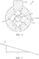
FIG. 4 is a cross-sectional illustration of a portion of the fuel nozzle taken along line 4-4 inFIG. 3 . -
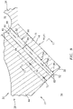
FIG. 5 is a graphic representation of a segment of an internal surface of the fuel nozzle at least partially forming a nozzle passage within the fuel nozzle. -
FIG. 6 is a cross-sectional illustration of a portion of the fuel nozzle taken along line 6-6 inFIG. 3 . -
FIG. 7 is a schematic representation of deviation in an additively manufactured, as-formed fuel nozzle internal surface from a standard. -
FIG. 8 is a schematic representation of deviation in another additively manufactured, as-formed fuel nozzle internal surface from another standard. -
FIG. 9 is a side sectional illustration of a portion of the turbine engine apparatus through the fuel nozzle with another nozzle passage configuration. -
FIG. 10 is a cross-sectional illustration of a portion of the fuel nozzle taken along line 10-10 inFIG. 9 . -
FIG. 11 is a sectional illustration of a portion of the fuel nozzle configured with a non-tapered exterior. -
FIG. 12 is a sectional illustration of a portion of the fuel nozzle configured with a tapered exterior. -
FIG. 13 is a cross-sectional illustration of a combustor section. -
FIG. 14 is a schematic side illustration of a single spool, radial flow turbojet turbine engine. -
FIG. 1 illustrates a portion of anapparatus 20 for a turbine engine. Thisturbine engine apparatus 20 is configured as, or otherwise includes, afuel injector assembly 22 for a combustor section of the turbine engine. Theturbine engine apparatus 20 includes afuel conduit 24 and afuel nozzle 26; e.g., a single and/or central orifice fuel nozzle. Theturbine engine apparatus 20 ofFIG. 1 may also include anapparatus base 28, whichapparatus base 28 may provide a structural support for thefuel conduit 24 and/or thefuel nozzle 26. - The
apparatus base 28 may be configured as any part of the turbine engine within the combustor section that is proximate thefuel injector assembly 22. Theapparatus base 28 ofFIG. 1 , for example, may be configured as a turbine engine case such as, but not limited to, a combustor section case, a diffuser case and/or a combustor wall. - The
fuel conduit 24 is configured as, or may be part of, a fuel supply for thefuel nozzle 26. Thefuel conduit 24, for example, may be or may be part of a fuel supply tube, a fuel inlet manifold and/or a fuel distribution manifold. Thefuel conduit 24 is arranged at and/or is connected to a first side 30 (e.g., an exterior and/or outer side) of theapparatus base 28. Thefuel conduit 24 is configured with an internalfuel supply passage 32 formed by an internal aperture (e.g., a bore, channel, etc.) within thefuel conduit 24. Thesupply passage 32 and the associated aperture extend within and/or through thefuel conduit 24 along a (e.g., curved and/or straight) centerline 34 of thesupply passage 32, which may also be a centerline of thefuel conduit 24. - Referring to
FIG. 2 , thefuel nozzle 26 is configured to receive (e.g., liquid) fuel from thefuel conduit 24, and inject that received fuel into a plenum 36 (e.g., a fluid passage such as an air passage) at a distal end 38 (e.g., tip) of thefuel nozzle 26. Thefuel nozzle 26 ofFIG. 2 includes anozzle body 40 and anozzle passage 42; e.g., a fuel passage. - The
nozzle body 40 is arranged at and/or is connected to a second side 44 (e.g., an interior and/or inner side) of theapparatus base 28, where the basesecond side 44 is opposite the basefirst side 30. Thenozzle body 40 ofFIG. 2 includes anozzle tube 46 and anozzle support structure 48; e.g., a web. A base end of thenozzle tube 46 is connected to theapparatus base 28. Thenozzle tube 46 projects longitudinally out from theapparatus base 28 along a (e.g., straight and/or curved)longitudinal centerline 50 of thenozzle passage 42 and/or thenozzle tube 46 to the fuel nozzledistal end 38. Thenozzle support structure 48 is connected to and extends between theapparatus base 28 and a (e.g., upstream) side of thenozzle tube 46. Thenozzle support structure 48 structurally ties thenozzle tube 46 to theapparatus base 28 and may thereby support thenozzle tube 46 within theplenum 36. Thenozzle support structure 48, for example, may form a support gusset for thenozzle tube 46. - An internal bore of the
nozzle tube 46 at least partially (or completely) forms thenozzle passage 42. Thenozzle passage 42 extends longitudinally along thelongitudinal centerline 50 within and/or through theapparatus base 28 and thenozzle tube 46 from thesupply passage 32 to adownstream nozzle orifice 52 at the fuel nozzledistal end 38. Thisnozzle orifice 52 provides an outlet from thenozzle passage 42 and, more generally, thefuel nozzle 26. - Referring to
FIG. 3 , thenozzle passage 42 includes one or more different flow portions (e.g., 54 and 56) arranged longitudinally along thelongitudinal centerline 50. Thenozzle passage 42 ofFIG. 3 , for example, includes a (e.g., upstream)convergent portion 54 and a (e.g., downstream)throat portion 56. - The
convergent portion 54 is upstream of thethroat portion 56, for example at (e.g., on, adjacent or proximate) anupstream end 58 of thenozzle passage 42. Theconvergent portion 54 ofFIG. 3 , for example, is formed by one or more tapering convergent sidewall surfaces 60; see alsoFIG. 4 . These convergent sidewall surfaces 60 and, thus, theconvergent portion 54 extend longitudinally along thelongitudinal centerline 50 from thesupply passage 32 to thethroat portion 56, thereby defining alongitudinal length 62 of theconvergent portion 54. - A lateral width 64 (e.g., a diagonal axis) of the convergent portion 54 (e.g., continuously) decreases as the
nozzle passage 42 extends longitudinally along thelongitudinal centerline 50 towards thethroat portion 56 / thenozzle orifice 52. The convergentportion lateral width 64 at the nozzle passageupstream end 58 is greater than the convergentportion lateral width 64 at thethroat portion 56. - A slope of a taper of the
convergent portion 54 and its tapering convergent sidewall surfaces 60 has a rise to run ratio (Y/X; seeFIG. 5 ). This convergent portion rise to run ratio may be equal to or less than about (e.g., +/- 1%) or exactly 0.6 (e.g., ≤ 0.577), for example, to minimize head loss due to contraction. For example, referring toFIG. 5 , for every five (5) units theconvergent portion 54 and its tapering convergent sidewall surfaces 60 extend longitudinally along the longitudinal centerline 50 (the run X), theconvergent portion 54 and its tapering convergent sidewall surfaces 60 may extend laterally (e.g., in a direction perpendicular to the longitudinal centerline 50) three (3) units (the rise Y). Such a convergent portion rise to run ratio may facilitate in the additive manufacturing of thefuel nozzle 26, for example, by minimizing layer-to-layer overhangs and/or minimizing variation in lateral sidewall thickness 66 (seeFIG. 4 ) of thenozzle tube 46. The present disclosure, however, is not limited to such an exemplary convergent portion rise to run ratio nor to any particular manufacturing techniques. For example, in some embodiments, the rise to run ratio may be equal to or less than 0.5, 0.4, 0.3, etc. In other embodiments, the rise to run ratio may be greater than 0.6, but less than 1 for example. - Referring to
FIG. 3 , thethroat portion 56 is downstream of theconvergent portion 54, for example at (e.g., on, adjacent or proximate) the fuel nozzledistal end 38. A downstream most end of thethroat portion 56 may also define thenozzle orifice 52. Thethroat portion 56 ofFIG. 3 , for example, is formed by one or more (e.g., non-tapered) throat sidewall surfaces 68 (see alsoFIG. 6 ). These throat sidewall surfaces 68 and, thus, thethroat portion 56 extend longitudinally along thelongitudinal centerline 50 from theconvergent portion 54 to (or towards) thenozzle orifice 52 in the fuel nozzledistal end 38, thereby defining alongitudinal length 70 of thethroat portion 56. - The throat portion
longitudinal length 70 may be different (e.g., less) than the convergent portionlongitudinal length 62. The convergent portionlongitudinal length 62, for example, may be more than two times (2x), five times (5x) or ten times (10x) the throat portionlongitudinal length 70. The present disclosure, however, is not limited to the foregoing dimensional relationship between the lengths. - A lateral width 72 (e.g., a
diagonal axis 74 as shown inFIG. 6 ) of thethroat portion 56 may be about (e.g., +/- 1%) or exactly constant as thenozzle passage 42 extends longitudinally along thelongitudinal centerline 50 towards thenozzle orifice 52. The throatportion lateral width 72 at theconvergent portion 54 is equal to the throatportion lateral width 72 at thenozzle orifice 52. Thus, thethroat portion 56 is non-tapered. - Referring to
FIGS. 4 and6 , one or more portion of thenozzle passage 42 may have a solid (e.g., non-annular) non-circular cross-sectional geometry (or other non-circular cross-sectional geometry), for example, when viewed in a plane perpendicular to thelongitudinal centerline 50. For example, eachnozzle passage portion nozzle passage 42 ofFIGS. 3 ,4 and6 has the (e.g., same) polygonal cross-sectional geometry. This polygonal cross-sectional geometry may be square shaped and/or diamond shaped as shown inFIGS. 4 and6 . The present disclosure, however, is not limited to such exemplary polygonal shapes. For example, in other embodiments, the polygonal cross-sectional geometry may have a triangular shape or any other polygonal shape. - Compared to a circular cross-sectional geometry for example, the polygonal cross-sectional geometry may aid in minimizing variation in as-formed surface finish (e.g., surface roughness and/or surface distortions) of the nozzle passage surfaces 60, 68, particularly where the
fuel nozzle 26 is additively manufactured and/or the nozzle passage lateral width (e.g., 64, 72; seeFIG. 3 ) is relatively small. Configuring thenozzle passage 42 with the polygonal cross-sectional geometry may thereby reduce actual (e.g., additively manufactured, as-formed) dimensional and/or geometric deviation of thenozzle passage 42 and itsnozzle orifice 52 from a (e.g., design) standard as schematically shown, for example, inFIG. 7 . By contrast, referring toFIG. 8 , layer-to-layer distortions produced during additive manufacturing may leave a nozzle passage 800 designed to have a circular cross-sectional geometry with a relative rough and/or otherwise distortednozzle passage surface 802. Such distortions may increase actual dimensional and/or geometric deviation of the circular nozzle passage 800 from its (e.g., design) standard. This increase in deviation particularly at a nozzle orifice 804 may reduce fuel metering precision through the circular nozzle orifice 804. Furthermore, where a turbine engine includes multiple fuel nozzles with the circular nozzle orifice 804, there may be a relatively significant deviation between the fuel injected by the fuel nozzles and, thus, a relatively high imbalance in fuel burn and hot streaks within the combustion chamber as well as downstream in the turbine section. However, by reducing the as-formed deviation as schematically shown inFIG. 7 by designing / providing thenozzle passage 42 and/or thenozzle orifice 52 with the polygonal cross-sectional geometry (or another non-circular cross-sectional geometry), fuel metering precision of thefuel nozzle 26 can be increased. Deviation betweenmultiple fuel nozzles 26 can also be reduced and, thus, fuel burn and/or hot streak imbalance may also be reduced. - Referring to
FIGS. 4 and6 , by reducing surface finish variation of the nozzle passage surfaces 60, 68, thefuel nozzle 26 may be designed with relatively small dimensions while still being producible via various manufacturing techniques including additive manufacturing. For example, thenozzle orifice 52 ofFIG. 6 is configured with a (e.g., minimum or maximum) lateral width (e.g., the lateral width 72) which may be equal to or less than about (e.g., +/- 1%) or exactly 0.0223 inches (0.0566 centimeters); e.g., ≤ 0.019 inches (0.0483 centimeters). In addition or alternatively, referring toFIG. 3 , atubular sidewall 76 of thenozzle tube 46 may have a (e.g., minimum, smallest)lateral thickness 78 equal to or less than about (e.g., +/- 1%) or exactly 0.010 inches (0.0254 centimeters). Note, at such relatively small dimensions for thenozzle orifice 52 and/or thetubular sidewall 76, normally micro-issues in additive manufacturing may become macro-issues and poor melting exhibited by unsupported features (e.g., faces) may cause blockages. However, reducing the surface finish variation as described above may mitigate or prevent formation of such blockages. The present disclosure, of course, is not limited to the foregoing exemplary fuel nozzle dimensions nor to any particular manufacturing technique. - Referring to
FIG. 2 , during turbine engine operation, (e.g., liquid) fuel is directed into thesupply passage 32 from a fuel source (not shown). At least a portion (or all) of the fuel within thesupply passage 32 is directed into thenozzle passage 42. This fuel flows through thenozzle passage 42 and out of thefuel nozzle 26 through thenozzle orifice 52 and into theplenum 36. The fuel within theplenum 36 may be mixed with air (e.g., compressed air) for subsequent combustion. - In some embodiments, referring to
FIG. 9 , thenozzle passage 42 may also be configured with aflow channel portion 80. Thisflow channel portion 80 is upstream of theconvergent portion 54, for example at (e.g., on, adjacent or proximate) the nozzle passageupstream end 58. Theflow channel portion 80 ofFIG. 9 , for example, is formed by at least one (e.g., non-tapering, cylindrical) flowchannel sidewall surface 82. This flowchannel sidewall surface 82 and, thus, theflow channel portion 80 extend longitudinally along thelongitudinal centerline 50 from thesupply passage 32 to theconvergent portion 54, thereby defining alongitudinal length 84 of theflow channel portion 80. - The flow channel portion
longitudinal length 84 may be different (e.g., greater) than the convergent portionlongitudinal length 62. The convergent portionlongitudinal length 62, for example, may be less than the flow channel portionlongitudinal length 84 but greater than fifteen percent (15%) of the flow channel portionlongitudinal length 84. More particularly, the convergent portionlongitudinal length 62 may be between twenty-five percent (25%) and seventy-five percent (75%) of the flow channel portionlongitudinal length 84. The present disclosure, however, is not limited to the foregoing dimensional relationship between thelengths longitudinal length 62 may be equal to or greater than the flow channel portionlongitudinal length 84. - A lateral width 86 (e.g., a diameter) of the
flow channel portion 80 may be about (e.g., +/- 1%) or exactly constant as thenozzle passage 42 extends longitudinally along thelongitudinal centerline 50 towards thethroat portion 56 / thenozzle orifice 52. The flow channelportion lateral width 86 at the nozzle passageupstream end 58 is equal to the flow channelportion lateral width 86 at theconvergent portion 54. Thus, theflow channel portion 80 is non-tapered. - In some embodiments, referring to
FIG. 9 , one portion of thenozzle passage 42 may have a different cross-sectional geometry than another portion of thenozzle passage 42, for example, when viewed in respective planes perpendicular to thelongitudinal centerline 50. Thethroat portion 56 and at least an adjacent section of theconvergent portion 54 ofFIG. 9 , for example, may each be configured with the (e.g., same) solid polygonal cross-sectional geometry (seeFIGS. 4 and6 ). By contrast, theflow channel portion 80 and at least an adjacent section of theconvergent portion 54 ofFIG. 9 may be configured with a different cross-sectional geometry (seeFIG. 10 ); e.g., a solid (e.g., non-annular) circular cross-sectional geometry or another solid (e.g., non-annular) polygonal, elongated (e.g., oval) or other cross-sectional geometry. Of course, in other embodiments, each of thenozzle passage portions - In some embodiments, referring to
FIG. 11 , at least a portion (or an entirety) of anexterior 88 of thefuel nozzle 26 and itsnozzle tube 46 may have aconstant lateral width 90 as the exterior 88 extends longitudinally along thelongitudinal centerline 50, for example, from the apparatus base 28 (seeFIG. 2 ) to (or towards) the fuel nozzledistal end 38 / thenozzle orifice 52. This at least a portion (or the entirety) of the exterior 88 may (e.g., partially or completely) longitudinally overlap any one or more of the nozzle passage portions (e.g., 54, 56 and/or 80; 80 not shown inFIG. 11 ) along thelongitudinal centerline 50. - In some embodiments, referring to
FIG. 12 , at least a portion (or the entirety) of theexterior 88 of thefuel nozzle 26 and itsnozzle tube 46 may have a variable lateral width 90'. Theexterior 88 ofFIG. 12 , for example, laterally tapers inward towards thelongitudinal centerline 50 as the exterior 88 extends longitudinally along thelongitudinal centerline 50, for example, from the apparatus base 28 (seeFIG. 2 ) to (or towards) the fuel nozzledistal end 38 / thenozzle orifice 52. This at least a portion (or the entirety) of the exterior 88 may (e.g., partially or completely) longitudinally overlap any one or more of the nozzle passage portions (e.g., 54, 56 and/or 80; 80 not shown inFIG. 11 ) along thelongitudinal centerline 50. - In some embodiments, referring to
FIG. 13 , thefuel nozzle 26 may be one of a plurality offuel nozzles 26 connected to theapparatus base 28 and fluidly coupled with thefuel conduit 24. Thesefuel nozzles 26 may be arranged circumferentially about a centerline /rotational axis 92 of the turbine engine in an annular array. - In some embodiments, the
turbine engine apparatus 20 may also include one or more fuel vaporizers 94. Eachfuel nozzle 26 is arranged with a respective one of the fuel vaporizers 94. More particularly, eachfuel nozzle 26 projects into a respective one of the fuel vaporizers 94 and is arranged within a fluid passage 96 (e.g., an air passage; theplenum 36 inFIGS. 1-3 ) of the respective fuel vaporizer 94. With such an arrangement, eachfuel nozzle 26 may direct at least a portion of the fuel injected into thefluid passage 96 against a (e.g., tubular)surface 98 of the respective fuel vaporizer 94. The fuel vaporizer 94 may at least partially vaporize the fuel impinging against itssurface 98. - In the specific embodiment of
FIG. 13 , each fuel vaporizer 94 is configured as a structure such as a flow tube 100 (e.g., a fluid tube, an air tube) for acombustor 102 in thecombustor section 104. Note, thecombustor 102 may also include at least oneflow tube 106 in between, for example, each circumferentially neighboring set of the vaporizers 94. Each of theflow tubes 100, 106 is connected to and projects out from awall 108 of thecombustor 102 and into a (e.g., annular)combustion chamber 110 at least partially defined by thecombustor wall 108. The fluid passage 96 (e.g., air passage) of each flow tube 100 is configured to receive fluid and, more particularly, compressed air from a compressor section of the turbine engine (not visible inFIG. 13 ) through anotherplenum 112. This compressed air is directed through therespective fluid passage 96 and into thecombustion chamber 110. However, before reaching thecombustion chamber 110, the air within therespective fluid passage 96 is mixed with fuel injected by a respective one of thefuel nozzles 26. By injecting the fuel within the flow tube 100, the fuel may be more likely to vaporize within therespective fluid passage 96; e.g., upon mixing with the airflow and/or upon impinging against the surface 98 (e.g., an inner side wall surface of the flow tube 100). - In some embodiments, still referring to
FIG. 13 (see alsoFIG. 2 ), at least theapparatus base 28, thefuel conduit 24 and eachfuel nozzle 26 may be configured together in an integral, monolithic body. Theturbine engine apparatus 20 and itselements FIG. 2 , the additive manufacturing may be performed to (e.g., completely) form eachnozzle passage 42 and its associatednozzle orifice 52, for example, without any additional machining (e.g., drilling of thenozzle elements 42 and/or 52). The present disclosure, however, is not limited to such an exemplary monolithic construction nor to additive manufacturing. For example, in other embodiments, one or more or all of theapparatus elements - The term additive manufacturing may describe a process where a component or components are formed by accumulating and/or fusing material together using an additive manufacturing device, typically in a layer-on-layer manner. Layers of powder material, for example, may be disposed and thereafter solidified sequentially onto one another to form the component(s). The term solidify may describe a process whereby material is sintered and/or otherwise melted thereby causing discrete particles or droplets of the sintered and/or melted material to fuse together. Examples of the additive manufacturing process include a laser powder bed fusion (LPBF) process and an electron beam powder bed fusion (EB-PBF) process. Examples of the additive manufacturing device include a laser powder bed fusion (LPBF) device and an electron beam powder bed fusion (EB-PBF) device. Of course, various other additive manufacturing processes and devices are known in the art, and the present disclosure is not limited to any particular ones thereof.
- The
turbine engine apparatus 20 of the present disclosure may be configured with various different types and configurations of turbine engines.FIG. 14 illustrates one such type and configuration of the turbine engine - a single spool, radial-flowturbojet turbine engine 114. Thisgas turbine engine 114 is configured for propelling an aircraft such as, but not limited to, an unmanned aerial vehicle (UAV), a drone or any other manned or unmanned aircraft or self-propelled projectile. The present disclosure, however, is not limited to such an exemplary turbojet turbine engine configuration nor to an aircraft propulsion system application. For example, the gas turbine engine may alternatively be configured as an auxiliary power unit (APU) or an industrial gas turbine engine. - In the specific embodiment of
FIG. 14 , theturbine engine 114 includes anupstream inlet 116, a (e.g., radial)compressor section 118, thecombustor section 104, a (e.g., radial)turbine section 120 and adownstream exhaust 122 fluidly coupled in series. Acompressor rotor 124 in thecompressor section 118 is coupled with aturbine rotor 126 in theturbine section 120 by ashaft 128, whichshaft 128 rotates about the centerline /rotational axis 92 of theturbine engine 114. - The
turbine engine apparatus 20 may be included in various turbine engines other than the one described above. Theturbine engine apparatus 20, for example, may be included in a geared turbine engine where a gear train connects one or more shafts to one or more rotors in a fan section, a compressor section and/or any other engine section. Alternatively, theturbine engine apparatus 20 may be included in a turbine engine configured without a gear train. Theturbine engine apparatus 20 may be included in a geared or non-geared turbine engine configured with a single spool (e.g., seeFIG. 14 ), with two spools, or with more than two spools. The turbine engine may be configured as a turbofan engine, a turbojet engine, a propfan engine, a pusher fan engine or any other type of turbine engine. The present disclosure therefore is not limited to any particular types or configurations of turbine engines. - While various embodiments of the present disclosure have been described, it will be apparent to those of ordinary skill in the art that many more embodiments and implementations are possible within the scope of the disclosure. For example, the present disclosure as described herein includes several aspects and embodiments that include particular features. Although these features may be described individually, it is within the scope of the present disclosure that some or all of these features may be combined with any one of the aspects and remain within the scope of the disclosure. Accordingly, the present disclosure is not to be restricted except in light of the attached claims and their equivalents.
Claims (15)
- An apparatus (20) for a turbine engine, comprising:a fuel nozzle (26) comprising a nozzle passage (42) and a nozzle orifice (52);the nozzle passage (42) extending longitudinally along a centerline (50) within the fuel nozzle (26) to the nozzle orifice (52); andthe nozzle passage (42) having a solid polygonal cross-sectional geometry at the nozzle orifice (52).
- The apparatus (20) of claim 1, wherein the solid polygonal cross-sectional geometry has a diamond shape or a square shape.
- The apparatus (20) of claim 1 or 2, wherein at least a first portion (54) of the nozzle passage (42) tapers inward towards the centerline (50) as the nozzle passage (42) extends longitudinally along the centerline (50) towards the nozzle orifice (52), and wherein, optionally, a slope of the taper of the first portion (54) has a rise to run ratio (Y/X) of less than 0.6.
- The apparatus (20) of claim 3, wherein:at least a first portion of an exterior (88) of the fuel nozzle (26) has a constant lateral width (90) as the exterior (88) of the fuel nozzle (26) extends longitudinally along the centerline (50) towards the nozzle orifice (52); andthe first portion of the exterior (88) of the fuel nozzle (26) longitudinally overlaps the first portion (54) of the nozzle passage (42) along the centerline (50).
- The apparatus (20) of claim 3 or 4, wherein:a second portion (56) of the nozzle passage (42) is longitudinally between the first portion (54) of the nozzle passage (42) and the nozzle orifice (52) along the centerline (50); andthe second portion (56) of the nozzle passage (42) has a constant lateral width (72) longitudinally along the centerline (50).
- The apparatus (20) of claim 5, wherein the first portion (54) of the nozzle passage (42) and the second portion (56) of the nozzle passage (42) each have the solid polygonal cross-sectional geometry.
- The apparatus (20) of any of claims 3 to 6, wherein:the first portion (54) of the nozzle passage (42) is longitudinally between the nozzle orifice (52) and a third portion (80) of the nozzle passage (42) along the centerline (50); andthe third portion (80) of the nozzle passage (42) has a constant lateral width (86) longitudinally along the centerline (50).
- The apparatus (20) of claim 7, wherein:the first portion (54) of the nozzle passage (42) has the solid polygonal cross-sectional geometry; andthe third portion (80) of the nozzle passage (42) has a second cross-sectional geometry that is different than the solid polygonal cross-sectional geometry.
- The apparatus (20) of any preceding claim, wherein:the solid polygonal cross-sectional geometry extends along a longitudinal length of the nozzle passage (42); and/orthe nozzle orifice (52) has a lateral width (72) less than 0.0223 inches (0.0566 centimeters).
- The apparatus (20) of any preceding claim, wherein:the fuel nozzle (26) has a tubular sidewall (76) forming the nozzle passage (42); andthe tubular sidewall (76) has a minimum lateral width (78) that is less than 0.01 inches (0.0254 centimeters).
- The apparatus (20) of any preceding claim, further comprising a fuel conduit (24) fluidly coupled with the fuel nozzle (26), the fuel nozzle (26) configured to receive fuel from the fuel conduit (24) within the nozzle passage (42), and the fuel nozzle (26) further configured to direct the fuel out of the nozzle passage (42) through the nozzle orifice (52).
- The apparatus (20) of any preceding claim, further comprising:an air tube (100) including an air passage (96);the fuel nozzle (26) projecting into the air passage (96); andthe fuel nozzle (26) configured to direct fuel out of the nozzle passage (42) through the nozzle orifice (52) into the air passage (96).
- The apparatus (20) of claim 12, further comprising a combustor wall (108) at least partially forming a combustion chamber (110), the air tube (100) connected to the combustor wall (108) and projecting into the combustion chamber (110).
- A method of manufacturing, comprising:additively manufacturing a fuel nozzle (26), the additively manufacturing providing the fuel nozzle (26) with a nozzle passage (42) and a nozzle orifice (52);the nozzle passage (42) extending longitudinally along a centerline (50) within the fuel nozzle (26) to the nozzle orifice (52); andat least a first portion (54) of the nozzle passage (42) tapering inward towards the centerline (50) as the nozzle passage (26) extends longitudinally along the centerline (50) towards the nozzle orifice (52), and a slope of the taper of the first portion (54) having a rise to run ratio (Y/X) of less than 0.6,wherein the nozzle passage (42) has a non-annular, non-circular cross-sectional geometry at the nozzle orifice (52).
- A method of manufacturing, comprising:additively manufacturing a fuel nozzle (26), the additively manufacturing providing the fuel nozzle (26) with a nozzle passage (42) and a nozzle orifice (52);the nozzle passage (42) extending longitudinally along a centerline (50) within the fuel nozzle (26) to the nozzle orifice (52); andthe nozzle orifice (52) having a lateral width (72) less than 0.0223 inches (0.0566 centimeters),wherein, optionally, the nozzle passage (42) has a square or diamond shaped cross-sectional geometry at the nozzle orifice (52).
Applications Claiming Priority (1)
| Application Number | Priority Date | Filing Date | Title |
|---|---|---|---|
| US17/221,222 US20220316400A1 (en) | 2021-04-02 | 2021-04-02 | Turbine engine fuel injector with non-circular nozzle passage |
Publications (2)
| Publication Number | Publication Date |
|---|---|
| EP4067747A1 true EP4067747A1 (en) | 2022-10-05 |
| EP4067747B1 EP4067747B1 (en) | 2025-06-25 |
Family
ID=81326262
Family Applications (1)
| Application Number | Title | Priority Date | Filing Date |
|---|---|---|---|
| EP22166587.0A Active EP4067747B1 (en) | 2021-04-02 | 2022-04-04 | Turbine engine fuel injector with polygonal nozzle passage |
Country Status (2)
| Country | Link |
|---|---|
| US (1) | US20220316400A1 (en) |
| EP (1) | EP4067747B1 (en) |
Families Citing this family (1)
| Publication number | Priority date | Publication date | Assignee | Title |
|---|---|---|---|---|
| US12529337B1 (en) * | 2024-11-18 | 2026-01-20 | Rtx Corporation | Additively manufactured turbine engine case with fuel manifold |
Citations (5)
| Publication number | Priority date | Publication date | Assignee | Title |
|---|---|---|---|---|
| US5277022A (en) * | 1990-06-22 | 1994-01-11 | Sundstrand Corporation | Air blast fuel injecton system |
| US20200109859A1 (en) * | 2018-10-04 | 2020-04-09 | United Technologies Corporation | Consumable support structures for additively manufactured combustor components |
| US20200173662A1 (en) * | 2018-11-29 | 2020-06-04 | General Electric Company | Premixed Fuel Nozzle |
| US20200182467A1 (en) * | 2018-12-07 | 2020-06-11 | United Technologies Corporation | Engine article with integral liner and nozzle |
| US20200191093A1 (en) * | 2018-12-12 | 2020-06-18 | General Electric Company | Combustion Section and Fuel Injector Assembly for a Heat Engine |
Family Cites Families (12)
| Publication number | Priority date | Publication date | Assignee | Title |
|---|---|---|---|---|
| US4967563A (en) * | 1988-12-12 | 1990-11-06 | Sundstrand Corporation | Turbine engine with high efficiency fuel atomization |
| US5241818A (en) * | 1989-07-13 | 1993-09-07 | Sundstrand Corporation | Fuel injector for a gas turbine engine |
| US5727378A (en) * | 1995-08-25 | 1998-03-17 | Great Lakes Helicopters Inc. | Gas turbine engine |
| US6931862B2 (en) * | 2003-04-30 | 2005-08-23 | Hamilton Sundstrand Corporation | Combustor system for an expendable gas turbine engine |
| US8313046B2 (en) * | 2009-08-04 | 2012-11-20 | Delavan Inc | Multi-point injector ring |
| US20120181355A1 (en) * | 2011-01-17 | 2012-07-19 | General Electric Company | System for flow control in fuel injectors |
| US9803498B2 (en) * | 2012-10-17 | 2017-10-31 | United Technologies Corporation | One-piece fuel nozzle for a thrust engine |
| JP2019100595A (en) * | 2017-11-30 | 2019-06-24 | 川崎重工業株式会社 | Burner device |
| US12050012B2 (en) * | 2020-03-31 | 2024-07-30 | Siemens Energy Global GmbH & Co. KG | Burner component of a burner, and burner of a gas turbine having a burner component of this type |
| DE102020119619A1 (en) * | 2020-07-24 | 2022-01-27 | Friedrich-Alexander-Universität Erlangen-Nürnberg | jet cluster |
| CN112484076B (en) * | 2020-11-12 | 2022-01-04 | 南京航空航天大学 | Special-shaped nozzle for main-stage oil supply of lean-oil premixed pre-evaporation low-pollution combustion chamber |
| US11795879B2 (en) * | 2021-12-20 | 2023-10-24 | General Electric Company | Combustor with an igniter provided within at least one of a fuel injector or a compressed air passage |
-
2021
- 2021-04-02 US US17/221,222 patent/US20220316400A1/en active Pending
-
2022
- 2022-04-04 EP EP22166587.0A patent/EP4067747B1/en active Active
Patent Citations (5)
| Publication number | Priority date | Publication date | Assignee | Title |
|---|---|---|---|---|
| US5277022A (en) * | 1990-06-22 | 1994-01-11 | Sundstrand Corporation | Air blast fuel injecton system |
| US20200109859A1 (en) * | 2018-10-04 | 2020-04-09 | United Technologies Corporation | Consumable support structures for additively manufactured combustor components |
| US20200173662A1 (en) * | 2018-11-29 | 2020-06-04 | General Electric Company | Premixed Fuel Nozzle |
| US20200182467A1 (en) * | 2018-12-07 | 2020-06-11 | United Technologies Corporation | Engine article with integral liner and nozzle |
| US20200191093A1 (en) * | 2018-12-12 | 2020-06-18 | General Electric Company | Combustion Section and Fuel Injector Assembly for a Heat Engine |
Also Published As
| Publication number | Publication date |
|---|---|
| EP4067747B1 (en) | 2025-06-25 |
| US20220316400A1 (en) | 2022-10-06 |
Similar Documents
| Publication | Publication Date | Title |
|---|---|---|
| DE112009000819B4 (en) | Swirl and method of making | |
| US11300295B2 (en) | Fuel nozzle structure for air assist injection | |
| RU2430307C2 (en) | Air-fuel mix injector, combustion chamber and gas turbine engine with said injector | |
| US11639795B2 (en) | Tapered fuel gallery for a fuel nozzle | |
| US12116934B2 (en) | Turbine engine fuel injector with oxygen circuit | |
| US11421883B2 (en) | Fuel injector assembly with a helical swirler passage for a turbine engine | |
| EP4001764B1 (en) | Fuel swirler for pressure fuel nozzles | |
| US20230296054A1 (en) | Nozzles with internal manifolding | |
| US12460573B2 (en) | Combustor size rating for a gas turbine engine using hydrogen fuel | |
| EP4067747B1 (en) | Turbine engine fuel injector with polygonal nozzle passage | |
| EP4339514B1 (en) | Method for manufacturing a fuel spray nozzle for gas turbine engine | |
| US11754287B2 (en) | Fuel injector assembly for a turbine engine | |
| US12546469B1 (en) | Gas turbine engine fuel injector with multiple fuel circuits | |
| US12560123B2 (en) | Arcuate fuel gallery for turbine engine fuel nozzle | |
| US20250067438A1 (en) | Heat shield for a gas turbine engine | |
| EP4481160A1 (en) | Support structure for forming turbine engine rotating structure | |
| US20260085836A1 (en) | Flow Assisted Integral Splash Plate | |
| CN121162401A (en) | Gas turbine engine including fuel injector |
Legal Events
| Date | Code | Title | Description |
|---|---|---|---|
| PUAI | Public reference made under article 153(3) epc to a published international application that has entered the european phase |
Free format text: ORIGINAL CODE: 0009012 |
|
| STAA | Information on the status of an ep patent application or granted ep patent |
Free format text: STATUS: THE APPLICATION HAS BEEN PUBLISHED |
|
| AK | Designated contracting states |
Kind code of ref document: A1 Designated state(s): AL AT BE BG CH CY CZ DE DK EE ES FI FR GB GR HR HU IE IS IT LI LT LU LV MC MK MT NL NO PL PT RO RS SE SI SK SM TR |
|
| STAA | Information on the status of an ep patent application or granted ep patent |
Free format text: STATUS: REQUEST FOR EXAMINATION WAS MADE |
|
| 17P | Request for examination filed |
Effective date: 20230405 |
|
| RBV | Designated contracting states (corrected) |
Designated state(s): AL AT BE BG CH CY CZ DE DK EE ES FI FR GB GR HR HU IE IS IT LI LT LU LV MC MK MT NL NO PL PT RO RS SE SI SK SM TR |
|
| RAP3 | Party data changed (applicant data changed or rights of an application transferred) |
Owner name: RTX CORPORATION |
|
| STAA | Information on the status of an ep patent application or granted ep patent |
Free format text: STATUS: EXAMINATION IS IN PROGRESS |
|
| 17Q | First examination report despatched |
Effective date: 20231115 |
|
| GRAP | Despatch of communication of intention to grant a patent |
Free format text: ORIGINAL CODE: EPIDOSNIGR1 |
|
| STAA | Information on the status of an ep patent application or granted ep patent |
Free format text: STATUS: GRANT OF PATENT IS INTENDED |
|
| INTG | Intention to grant announced |
Effective date: 20250124 |
|
| GRAS | Grant fee paid |
Free format text: ORIGINAL CODE: EPIDOSNIGR3 |
|
| GRAA | (expected) grant |
Free format text: ORIGINAL CODE: 0009210 |
|
| STAA | Information on the status of an ep patent application or granted ep patent |
Free format text: STATUS: THE PATENT HAS BEEN GRANTED |
|
| AK | Designated contracting states |
Kind code of ref document: B1 Designated state(s): AL AT BE BG CH CY CZ DE DK EE ES FI FR GB GR HR HU IE IS IT LI LT LU LV MC MK MT NL NO PL PT RO RS SE SI SK SM TR |
|
| REG | Reference to a national code |
Ref country code: GB Ref legal event code: FG4D |
|
| REG | Reference to a national code |
Ref country code: CH Ref legal event code: EP |
|
| REG | Reference to a national code |
Ref country code: DE Ref legal event code: R096 Ref document number: 602022016301 Country of ref document: DE |
|
| REG | Reference to a national code |
Ref country code: CH Ref legal event code: EP |
|
| REG | Reference to a national code |
Ref country code: IE Ref legal event code: FG4D |
|
| PG25 | Lapsed in a contracting state [announced via postgrant information from national office to epo] |
Ref country code: FI Free format text: LAPSE BECAUSE OF FAILURE TO SUBMIT A TRANSLATION OF THE DESCRIPTION OR TO PAY THE FEE WITHIN THE PRESCRIBED TIME-LIMIT Effective date: 20250625 |
|
| REG | Reference to a national code |
Ref country code: LT Ref legal event code: MG9D |
|
| PG25 | Lapsed in a contracting state [announced via postgrant information from national office to epo] |
Ref country code: NO Free format text: LAPSE BECAUSE OF FAILURE TO SUBMIT A TRANSLATION OF THE DESCRIPTION OR TO PAY THE FEE WITHIN THE PRESCRIBED TIME-LIMIT Effective date: 20250925 Ref country code: GR Free format text: LAPSE BECAUSE OF FAILURE TO SUBMIT A TRANSLATION OF THE DESCRIPTION OR TO PAY THE FEE WITHIN THE PRESCRIBED TIME-LIMIT Effective date: 20250926 |
|
| PG25 | Lapsed in a contracting state [announced via postgrant information from national office to epo] |
Ref country code: BG Free format text: LAPSE BECAUSE OF FAILURE TO SUBMIT A TRANSLATION OF THE DESCRIPTION OR TO PAY THE FEE WITHIN THE PRESCRIBED TIME-LIMIT Effective date: 20250625 |
|
| PG25 | Lapsed in a contracting state [announced via postgrant information from national office to epo] |
Ref country code: HR Free format text: LAPSE BECAUSE OF FAILURE TO SUBMIT A TRANSLATION OF THE DESCRIPTION OR TO PAY THE FEE WITHIN THE PRESCRIBED TIME-LIMIT Effective date: 20250625 |
|
| PG25 | Lapsed in a contracting state [announced via postgrant information from national office to epo] |
Ref country code: RS Free format text: LAPSE BECAUSE OF FAILURE TO SUBMIT A TRANSLATION OF THE DESCRIPTION OR TO PAY THE FEE WITHIN THE PRESCRIBED TIME-LIMIT Effective date: 20250925 |
|
| PG25 | Lapsed in a contracting state [announced via postgrant information from national office to epo] |
Ref country code: LV Free format text: LAPSE BECAUSE OF FAILURE TO SUBMIT A TRANSLATION OF THE DESCRIPTION OR TO PAY THE FEE WITHIN THE PRESCRIBED TIME-LIMIT Effective date: 20250625 |
|
| REG | Reference to a national code |
Ref country code: NL Ref legal event code: MP Effective date: 20250625 |
|
| PG25 | Lapsed in a contracting state [announced via postgrant information from national office to epo] |
Ref country code: NL Free format text: LAPSE BECAUSE OF FAILURE TO SUBMIT A TRANSLATION OF THE DESCRIPTION OR TO PAY THE FEE WITHIN THE PRESCRIBED TIME-LIMIT Effective date: 20250625 |
|
| PG25 | Lapsed in a contracting state [announced via postgrant information from national office to epo] |
Ref country code: PT Free format text: LAPSE BECAUSE OF FAILURE TO SUBMIT A TRANSLATION OF THE DESCRIPTION OR TO PAY THE FEE WITHIN THE PRESCRIBED TIME-LIMIT Effective date: 20251027 |
|
| REG | Reference to a national code |
Ref country code: AT Ref legal event code: MK05 Ref document number: 1806772 Country of ref document: AT Kind code of ref document: T Effective date: 20250625 |
|
| PG25 | Lapsed in a contracting state [announced via postgrant information from national office to epo] |
Ref country code: IS Free format text: LAPSE BECAUSE OF FAILURE TO SUBMIT A TRANSLATION OF THE DESCRIPTION OR TO PAY THE FEE WITHIN THE PRESCRIBED TIME-LIMIT Effective date: 20251025 |
|
| PG25 | Lapsed in a contracting state [announced via postgrant information from national office to epo] |
Ref country code: AT Free format text: LAPSE BECAUSE OF FAILURE TO SUBMIT A TRANSLATION OF THE DESCRIPTION OR TO PAY THE FEE WITHIN THE PRESCRIBED TIME-LIMIT Effective date: 20250625 Ref country code: SM Free format text: LAPSE BECAUSE OF FAILURE TO SUBMIT A TRANSLATION OF THE DESCRIPTION OR TO PAY THE FEE WITHIN THE PRESCRIBED TIME-LIMIT Effective date: 20250625 |
|
| PG25 | Lapsed in a contracting state [announced via postgrant information from national office to epo] |
Ref country code: CZ Free format text: LAPSE BECAUSE OF FAILURE TO SUBMIT A TRANSLATION OF THE DESCRIPTION OR TO PAY THE FEE WITHIN THE PRESCRIBED TIME-LIMIT Effective date: 20250625 |
|
| PG25 | Lapsed in a contracting state [announced via postgrant information from national office to epo] |
Ref country code: PL Free format text: LAPSE BECAUSE OF FAILURE TO SUBMIT A TRANSLATION OF THE DESCRIPTION OR TO PAY THE FEE WITHIN THE PRESCRIBED TIME-LIMIT Effective date: 20250625 |
|
| PG25 | Lapsed in a contracting state [announced via postgrant information from national office to epo] |
Ref country code: EE Free format text: LAPSE BECAUSE OF FAILURE TO SUBMIT A TRANSLATION OF THE DESCRIPTION OR TO PAY THE FEE WITHIN THE PRESCRIBED TIME-LIMIT Effective date: 20250625 |
|
| PG25 | Lapsed in a contracting state [announced via postgrant information from national office to epo] |
Ref country code: SK Free format text: LAPSE BECAUSE OF FAILURE TO SUBMIT A TRANSLATION OF THE DESCRIPTION OR TO PAY THE FEE WITHIN THE PRESCRIBED TIME-LIMIT Effective date: 20250625 |
|
| PG25 | Lapsed in a contracting state [announced via postgrant information from national office to epo] |
Ref country code: ES Free format text: LAPSE BECAUSE OF FAILURE TO SUBMIT A TRANSLATION OF THE DESCRIPTION OR TO PAY THE FEE WITHIN THE PRESCRIBED TIME-LIMIT Effective date: 20250625 |
|
| PGFP | Annual fee paid to national office [announced via postgrant information from national office to epo] |
Ref country code: GB Payment date: 20260319 Year of fee payment: 5 |
|
| PG25 | Lapsed in a contracting state [announced via postgrant information from national office to epo] |
Ref country code: DK Free format text: LAPSE BECAUSE OF FAILURE TO SUBMIT A TRANSLATION OF THE DESCRIPTION OR TO PAY THE FEE WITHIN THE PRESCRIBED TIME-LIMIT Effective date: 20250625 |
|
| PG25 | Lapsed in a contracting state [announced via postgrant information from national office to epo] |
Ref country code: IT Free format text: LAPSE BECAUSE OF FAILURE TO SUBMIT A TRANSLATION OF THE DESCRIPTION OR TO PAY THE FEE WITHIN THE PRESCRIBED TIME-LIMIT Effective date: 20250625 |
|
| PGFP | Annual fee paid to national office [announced via postgrant information from national office to epo] |
Ref country code: FR Payment date: 20260320 Year of fee payment: 5 |
|
| PLBE | No opposition filed within time limit |
Free format text: ORIGINAL CODE: 0009261 |
|
| STAA | Information on the status of an ep patent application or granted ep patent |
Free format text: STATUS: NO OPPOSITION FILED WITHIN TIME LIMIT |
|
| REG | Reference to a national code |
Ref country code: CH Ref legal event code: L10 Free format text: ST27 STATUS EVENT CODE: U-0-0-L10-L00 (AS PROVIDED BY THE NATIONAL OFFICE) Effective date: 20260507 |