EP4067720A1 - Disassembly-prevention nut assembly and air conditioning system - Google Patents
Disassembly-prevention nut assembly and air conditioning system Download PDFInfo
- Publication number
- EP4067720A1 EP4067720A1 EP20895221.8A EP20895221A EP4067720A1 EP 4067720 A1 EP4067720 A1 EP 4067720A1 EP 20895221 A EP20895221 A EP 20895221A EP 4067720 A1 EP4067720 A1 EP 4067720A1
- Authority
- EP
- European Patent Office
- Prior art keywords
- nut
- connection
- disassembly
- pipe connector
- prevention
- Prior art date
- Legal status (The legal status is an assumption and is not a legal conclusion. Google has not performed a legal analysis and makes no representation as to the accuracy of the status listed.)
- Granted
Links
Images


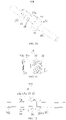
Classifications
-
- F—MECHANICAL ENGINEERING; LIGHTING; HEATING; WEAPONS; BLASTING
- F16—ENGINEERING ELEMENTS AND UNITS; GENERAL MEASURES FOR PRODUCING AND MAINTAINING EFFECTIVE FUNCTIONING OF MACHINES OR INSTALLATIONS; THERMAL INSULATION IN GENERAL
- F16L—PIPES; JOINTS OR FITTINGS FOR PIPES; SUPPORTS FOR PIPES, CABLES OR PROTECTIVE TUBING; MEANS FOR THERMAL INSULATION IN GENERAL
- F16L19/00—Joints in which sealing surfaces are pressed together by means of a member, e.g. a swivel nut, screwed on, or into, one of the joint parts
- F16L19/02—Pipe ends provided with collars or flanges, integral with the pipe or not, pressed together by a screwed member
-
- F—MECHANICAL ENGINEERING; LIGHTING; HEATING; WEAPONS; BLASTING
- F16—ENGINEERING ELEMENTS AND UNITS; GENERAL MEASURES FOR PRODUCING AND MAINTAINING EFFECTIVE FUNCTIONING OF MACHINES OR INSTALLATIONS; THERMAL INSULATION IN GENERAL
- F16L—PIPES; JOINTS OR FITTINGS FOR PIPES; SUPPORTS FOR PIPES, CABLES OR PROTECTIVE TUBING; MEANS FOR THERMAL INSULATION IN GENERAL
- F16L19/00—Joints in which sealing surfaces are pressed together by means of a member, e.g. a swivel nut, screwed on, or into, one of the joint parts
- F16L19/02—Pipe ends provided with collars or flanges, integral with the pipe or not, pressed together by a screwed member
- F16L19/025—Pipe ends provided with collars or flanges, integral with the pipe or not, pressed together by a screwed member the pipe ends having integral collars or flanges
- F16L19/028—Pipe ends provided with collars or flanges, integral with the pipe or not, pressed together by a screwed member the pipe ends having integral collars or flanges the collars or flanges being obtained by deformation of the pipe wall
-
- F—MECHANICAL ENGINEERING; LIGHTING; HEATING; WEAPONS; BLASTING
- F16—ENGINEERING ELEMENTS AND UNITS; GENERAL MEASURES FOR PRODUCING AND MAINTAINING EFFECTIVE FUNCTIONING OF MACHINES OR INSTALLATIONS; THERMAL INSULATION IN GENERAL
- F16B—DEVICES FOR FASTENING OR SECURING CONSTRUCTIONAL ELEMENTS OR MACHINE PARTS TOGETHER, e.g. NAILS, BOLTS, CIRCLIPS, CLAMPS, CLIPS OR WEDGES; JOINTS OR JOINTING
- F16B39/00—Locking of screws, bolts or nuts
- F16B39/02—Locking of screws, bolts or nuts in which the locking takes place after screwing down
- F16B39/12—Locking of screws, bolts or nuts in which the locking takes place after screwing down by means of locknuts
-
- F—MECHANICAL ENGINEERING; LIGHTING; HEATING; WEAPONS; BLASTING
- F16—ENGINEERING ELEMENTS AND UNITS; GENERAL MEASURES FOR PRODUCING AND MAINTAINING EFFECTIVE FUNCTIONING OF MACHINES OR INSTALLATIONS; THERMAL INSULATION IN GENERAL
- F16L—PIPES; JOINTS OR FITTINGS FOR PIPES; SUPPORTS FOR PIPES, CABLES OR PROTECTIVE TUBING; MEANS FOR THERMAL INSULATION IN GENERAL
- F16L19/00—Joints in which sealing surfaces are pressed together by means of a member, e.g. a swivel nut, screwed on, or into, one of the joint parts
- F16L19/005—Joints in which sealing surfaces are pressed together by means of a member, e.g. a swivel nut, screwed on, or into, one of the joint parts comprising locking means for the threaded member
-
- F—MECHANICAL ENGINEERING; LIGHTING; HEATING; WEAPONS; BLASTING
- F16—ENGINEERING ELEMENTS AND UNITS; GENERAL MEASURES FOR PRODUCING AND MAINTAINING EFFECTIVE FUNCTIONING OF MACHINES OR INSTALLATIONS; THERMAL INSULATION IN GENERAL
- F16L—PIPES; JOINTS OR FITTINGS FOR PIPES; SUPPORTS FOR PIPES, CABLES OR PROTECTIVE TUBING; MEANS FOR THERMAL INSULATION IN GENERAL
- F16L2201/00—Special arrangements for pipe couplings
- F16L2201/20—Safety or protective couplings
Definitions
- the present invention relates to refrigeration equipment, in particular to a disassembly-prevention nut assembly and an air conditioning system.
- a pipe connector and a connection pipe is able to be fixed with a connection nut.
- An end of the connection pipe is installed in the connection nut.
- the connection nut is rotated and tightly connected to the pipe connector by applying a locking torque to the connection nut, so that the connection pipe can be locked to the pipe connector.
- the pipe connector can be removed from the connection pipe if the connection nut is rotated backwards, which cannot meet an installation requirement of the indoor side of the air conditioning system using the flammable refrigerant.
- the present invention provides a disassembly-prevention nut assembly for fixing a first connection pipe and a second connection pipe.
- the disassembly-prevention nut assembly includes a pipe connector, a connection nut and a disassembly-prevention nut.
- a first end of the connection nut is fixed to the first connection pipe
- the pipe connector is sleeved on and fixed to the second connection pipe.
- the pipe connector extends in and is threadedly connected to a second end of the connection nut.
- the disassembly-prevention nut is sleeved on and threadedly connected to the pipe connector or the connection nut.
- the disassembly-prevention nut assembly as described above has the following advantages.
- connection nut By mounting the disassembly-prevention nut on the connection nut or the pipe connector, the connection nut can be anti-disassembly connected to the pipe connector, so that the first connection pipe can be anti-disassembly connected to the second connection pipe.
- the disassembly-prevention nut is sleeved on the connection nut and threadedly connected to the second end relatively away from the first connection pipe of the connection nut.
- An inner screw thread being capable of connecting with the pipe connector is defined on an inner surface of the connection nut
- an outer screw thread being capable of connecting with the disassembly-prevention nut is defined on an outer surface of the connection nut, and a spiral direction of the inner screw thread of the connection nut is opposite to that of the outer screw thread of the connection nut.
- a connection length between the disassembly-prevention nut and the connection nut is shorter than that between the connection nut and the pipe connector.
- an outer surface of the connection nut includes a thread portion and a smooth portion, and the disassembly-prevention nut is threadedly connected with the third thread portion.
- the pipe connector includes an assembling portion having a non-circular-shaped outer surface, and the disassembly-prevention nut is an outer hexagon-shaped nut.
- the disassembly-prevention nut is sleeved on and threadedly connected to the pipe connector.
- a first thread portion is defined on a first end relatively close to the first connection pipe of the pipe connector, and the first thread portion is capable of threadedly connecting with the connection nut.
- a second thread portion is defined on a second end of the pipe connector, the second thread portion is capable of threadedly connecting with the disassembly-prevention nut, and a spiral direction of the first thread portion is opposite to that of the second thread portion.
- a first thread portion is defined on a first end relatively close to the first connection pipe of the pipe connector, and the first thread portion is capable of threadedly connecting with the connection nut.
- a second thread portion is defined on a second end relatively away from the first connection pipe of the pipe connector, the second thread portion is capable of threadedly connecting with the disassembly-prevention nut, and a spiral direction of the first thread portion is the same with that of the second thread portion.
- a limiting portion is defined on the second end of the pipe connector extending along an axial direction of the pipe connector, and the limiting portion abuts against the disassembly-prevention nut.
- a connection length between the disassembly-prevention nut and the pipe connector is shorter than that between the connection nut and the pipe connector.
- connection nut includes a twisting portion having a non-circular shaped outer surface
- disassembly-prevention nut is an outer hexagon-shaped nut
- a screw thread disposed on an inner surface of the disassembly-prevention nut (30) extends to both ends of the disassembly-prevention nut.
- the screw thread disposed on the inner surface of the disassembly-prevention nut extends to one end of the disassembly-prevention nut.
- the present invention further provides an air conditioning system, including a first connection pipe, a second connection pipe and the disassembly-prevention nut assembly as described above.
- the first connection pipe is connected to the pipe connector by welding, and the second connection pipe abuts against and is fixed in the connection nut via the pipe connector.
- 100 represents a disassembly-prevention nut assembly
- 10 represents a pipe connector
- 11 represents an assembling portion
- 12 represents an abutting portion
- 13 represents a first thread portion
- 14/14a represents a second thread portion
- 15/15a represents a limiting portion
- 20 represents a connection nut
- 21 represents a third thread portion
- 22 represents a smooth portion
- 23 represents a twisting portion
- 30 represents a disassembly-prevention nut
- 201 represents a first connection pipe
- 2011 represents an expansion portion
- 202 represents a second connection pipe.
- a disassembly-prevention nut assembly and an air conditioning system provided in the present invention are further described below.
- the present invention provides a disassembly-prevention nut assembly 100, which is installed in an indoor unit of an air conditioner to prevent accidental disassembly of refrigerant connection pipes.
- disassembly-prevention nut assembly 100 mentioned above can also be used in other devices that need to be installed with anti-disassembly structures, such as refrigerators.
- the disassembly-prevention nut assembly 100 further includes a disassembly-prevention nut 30, so that a pipe connector 10 is non-detachably connected to a connection nut 20.
- the disassembly-prevention nut assembly 100 includes a pipe connector 10, a connection nut 20 and a disassembly-prevention nut 30.
- the pipe connector 10 is configured for threadedly connected with the connection nut 20, while fixing the first connection pipe 201 in the connection nut 20.
- the connection nut 20 is configured to connect with the pipe connector 10, and the disassembly-prevention nut 30 is configured to further tighten connection between the pipe connector 10 and the connection nut 20 and prevent the pipe connector 10 and the connection nut 20 from disassembling.
- the disassembly-prevention nut assembly 100 is described by the following three embodiments.
- FIG. 1 is a structural schematic diagram of connection between a disassembly-prevention nut assembly 100, a first connection pipe 201 and a second connection pipe 202 in an embodiment of the present disclosure.
- connection nut 20 A first end of the connection nut 20 is sleeved on and fixed to the first connection pipe 201, and a second end of the connection nut 20 is threadedly connected to the pipe connector 10.
- the first connection pipe 201 is inserted in the connection nut 20 and abuts against the pipe connector 10.
- the pipe connector 10 Upon a condition that the pipe connector 10 is threadedly connected with the connection nut 20 to a maximum extent, the pipe connector 10 abuts against the first connection pipe 201.
- the disassembly-prevention nut 30 is threadedly connected to the second end relatively away from the first connection pipe 201 of the connection nut 20, and the second connection pipe 202 is inserted in and fixed to an end of the pipe connector 10 away from the first connection pipe 201.
- connection between the pipe connector 10 and the connection nut 20 can hardly be removed directly by an ordinary user of the air conditioner, so that the pipes of the indoor unit of the air conditioner cannot be disassembled.
- the pipe connector 10 is approximately cylinder-shaped, one end of the pipe connector 10 away from the first connection pipe 201 extends radially and forms an assembling portion 11, and the other end of the pipe connector 10 contracts radially and forms an abutting portion 12.
- An outer surface close to the abutting portion 12 of the pipe connector 10 is provided with a first thread portion 13.
- the assembling portion 11 is configured for screwing the pipe connector 10 to the connection nut 20 using a tool
- the abutting portion 12 is configured for abutting against the first connection pipe 201
- the first thread portion 13 is configured to threadedly connect with the connection nut 20.
- the second connection pipe 202 is inserted and fixed in the assembling portion 11 by methods of welding, riveting and the like, so as to ensure the sealing between the second connection pipe 202 and the assembling portion 11.
- the assembling portion 11 in order to facilitate a tool to screw the pipe connector 10 into the connection nut 20, can be substantially an outer hexagon-shaped prism.
- the shape of the assembling portion 11 can be in other non-circular structures, such as triangle-shaped prisms, as long as it can facilitate a tool to screw the pipe connector 10 into the connection nut 20.
- FIG. 2 is a structural schematic diagram of a connection nut and a disassembly-prevention nut of the disassembly-prevention nut assembly in FIG. 1.
- FIG. 3 is a section view of a disassembly-prevention nut and a connection nut in a tightened state of the disassembly-prevention nut assembly in FIG. 1 .
- FIG. 4 is a section view of the disassembly-prevention nut and the connection nut in an untightened state of the disassembly-prevention nut assembly in FIG. 3 .
- connection nut 20 is substantially a cylinder-shaped nut with threads configured to connect with the pipe connector 10 on an inner surface of the connection nut 20.
- An end extending into the connection nut 20 of the first connection pipe 201 is defined as an expansion portion 2011.
- the expansion portion 2011 is configured to prevent the first connection pipe 201 from pulling out the connection nut 20 directly.
- the connection nut 20 is provided with a housing cavity that is capable of accommodating the first connection pipe 201, and the housing cavity is provided with a shrinkage port structure to prevent the first connection pipe 201 from detaching.
- An outer surface of the expansion portion 2011 is attached to the inner wall of the shrinkage port.
- a shrinkage shape of the abutting portion 12 of the pipe connector 10 is also set corresponding to the expansion portion 2011 of the first connection pipe 201, so as to ensure that the abutting portion 12 can closely contact with and seal the first connection pipe 201.
- the abutting portion 12 of the pipe connector 10 abuts against an inner surface of the expansion portion 2011 of the first connection pipe 201, so that the first connection pipe 201 is sealed and fixed to a position between the pipe connector 10 and the connection nut 20.
- the disassembly-prevention nut 30 is an outer hexagon-shaped nut, which is sleeved on a second end relatively away from the first connection pipe 201 of the connection nut 20.
- an outer surface of the connection nut 20 includes a third thread portion 21, and the third thread portion 21 is configured for threadedly connecting with the disassembly-prevention nut 30.
- the connection nut 20 is further provided with a smooth portion 22 connected to the third thread portion 21, and a dimension of the smooth portion 22 equals to that of the third thread portion 21.
- the smooth portion 22 is configured to prevent the disassembly-prevention nut 30 from being screwed out of the connection nut 20 directly.
- the disassembly-prevention nut 30 is arranged between the pipe connector 10 and the connection nut 20, and the inner dimension of the disassembly-prevention nut 30 is smaller than the outer dimension of the assembling portion 11, making the disassembly-prevention nut 30 not easily to be lost during installation, and facilitating direct installation of the connection by the installer.
- the disassembly-prevention nut 30 Upon a condition that the disassembly-prevention nut 30 is threadedly connected with the third thread portion 21 to a maximum extent, the disassembly-prevention nut 30 is further screwed until surfaces of an inner screw thread of the disassembly-prevention nut 30 and the third thread portion 21 produce screw loose. At this time, it is difficult for the disassembly-prevention nut 30 to be screwed in or out by a tool, and the connection nut 20 cannot be further screwed in or out, thus further ensuring a non-detachably connection between the disassembly-prevention nut 30 and the connection nut 20.
- the disassembly-prevention nut 30 in the present embodiment is an outer hexagon-shaped nut. In this way, on the one hand, it is easier and saves effort for the installer to rotate the disassembly-prevention nut 30, and on the other hand, the disassembly-prevention nut 30 can be used with various existing wrench tools, increasing the range of wrench tools to choose.
- the disassembly-prevention nut 30 may also be in other shapes, such as a pentagon-shaped nut, as long as the disassembly-prevention nut 30 can be easily connected to the connection nut 20.
- the connection nut 20 may further be in other structures to prevent the disassembly-prevention nut 30 from being directly screwed out of the connection nut 20. For example, by providing a limiting portion on the outer surface of the connection nut 20, as long as the structure can prevent the disassembly-prevention nut 30 from being screwed out directly of the connection nut 20.
- hardness of the disassembly-prevention nut 30 is lower than hardness of the pipe connector 10 or the connection nut 20. In this way, upon a condition that screw loose is generated between the surfaces of the disassembly-prevention nut 30 and the connection nut 20, an inner screw thread of the disassembly-prevention nut 30 are damaged, while neither the pipe connector 10 nor the connection nut 20 is damaged.
- an outer screw thread being capable of connecting with the disassembly-prevention nut 30 is defined on an outer surface of the connection nut 20
- an inner screw thread being capable of connecting with the pipe connector 10 is defined on an inner surface of the connection nut 20.
- a spiral direction of the inner screw thread of the connection nut 20 is opposite to that of the outer screw thread of the connection nut 20. That is, a direction of the disassembly-prevention nut 30 screwed into the connection nut 20 is opposite to a direction of the connection nut 20 screwed into the pipe connector 10.
- the disassembly-prevention nut 30 can further drive the connection nut 20 to screw into the pipe connector 10 while being tightened, and prevent the connection nut 20 from being screwed out of the pipe connector 10.
- the inner screw thread on the inner surface of the connection nut 20 can be a right-hand thread and the outer screw thread on the outer surface of the connection nut 20 can be a left-hand thread on the contrary.
- a direction F1 in which the installer screws the disassembly-prevention nut 30 into the connection nut 20 and a direction F2 in which the pipe connector 10 is screwed into the connection nut 20 are shown in FIG. 1 , respectively.
- the direction in which the pipe connector 10 screwed into the connection nut 20 is opposite to the direction of F2 in the FIG. 1 .
- a biting depth between the connection nut 20 and the pipe connector 10 is deeper than that between the disassembly-prevention nut 30 and the connection nut 10. Therefore, a force of the pipe connector 10 screwed into the connection nut 20 is greater than a force of the disassembly-prevention nut 30 screwed into the connection nut 20. In this way, upon a condition that screw loose is generated between surfaces of the inner screw thread of the disassembly-prevention nut 30 and the third thread portion 21, screw loose is hardly generated between the connection nut 20 and the pipe connector 10.
- a connection length between the connection nut 20 and the pipe connector 10 is longer than that between the disassembly-prevention nut 30 and the connection nut 20.
- the number of screw threads between the connection nut 20 and pipe connector 10 is greater than that between the disassembly-prevention nut 30 and the connection nut 20.
- the inner screw thread disposed on an inner surface of the disassembly-prevention nut 30 extends between both ends of the disassembly-prevention nut 30, so that the connection strength between the disassembly-prevention nut 30 and the connection nut 20 is greater.
- the inner screw thread disposed on the inner surface of the disassembly-prevention nut 30 extends to one end of the disassembly-prevention nut 30, so that the processing of the disassembly-prevention nut 30 is convenient and timesaving, and the processing cost is reduced.
- a process of fixing the disassembly-prevention nut assembly 100 to the first connection pipe 201 or the second connection pipe 202 is shown hereinafter.
- an end of the first connection pipe 201 with the expansion portion 2011 is inserted into the connection nut 20, and extends out from a first end of the connection nut 20, and the pipe connector 10 is screwed into the second end of the connection nut 20 along the direction F2 with a wrench to fix the pipe connector 10. Then the pipe connector 10 is tightened and abuts against the expansion portion 2011 of the first connection pipe 201, so that a wall of the expansion portion 2011 is clamped between the pipe connector 10 and the connection nut 20.
- the disassembly-prevention nut 30 is screwed along the direction F1, and drives the pipe connector 10 further screw into the connection nut 20, so that the first connection pipe 201 can be further compressed.
- the disassembly-prevention nut 30 is further screwed along the direction F1.
- the threaded connection strength between the disassembly-prevention nut 30 and the connection nut 20 is smaller than the threaded connection strength between the connection nut 20 and the pipe connector 10
- screw loose is generated between the disassembly-prevention nut 30 and the connection nut 20. That is, the inner thread of the disassembly-prevention nut 30 and the outer thread of the third thread portion 21 cannot be engaged.
- the connection nut 20 does not rotate.
- connection nut 20 since the outer surface of the smooth portion 22 is a smooth surface, it is impossible to rotate the connection nut 20 by other tools and loosen the connection nut 20. Therefore, the requirement that the connection nut 20 is disassembled is achieved, preventing the leakage of refrigerant caused by manual disassembly.
- FIG. 5 is a structural schematic diagram of connection between a disassembly-prevention nut assembly 100, a first connection pipe 201, and a second connection pipe 202 in an embodiment of the present invention.
- FIG. 6 is a structural schematic diagram of a pipe connector 10 of the disassembly-prevention nut assembly 100 in FIG. 5 .
- FIG. 7 is a structural schematic diagram of a disassembly-prevention nut 30 and a pipe connector 10 in an untightened state of the disassembly-prevention nut assembly 100 in FIG. 5 .
- the first connection pipe 201 is inserted in a first end of the connection nut 20, and a second end of the connection nut 20 is threadedly connected the pipe connector 10.
- the first connection pipe 201 is inserted in the connection nut 20 and abuts against the pipe connector 10.
- the pipe connector 10 Upon a condition that the pipe connector 10 is threadedly connected with the connection nut 20 to a maximum extent, the pipe connector 10 abuts against the first connection pipe 201.
- the disassembly-prevention nut 30 is threadedly connected to the pipe connector 10, and the second connection pipe 202 is inserted in and fixed to a second end of the pipe connector 10 away from the first connection pipe 201.
- the connection between the pipe connector 10 and the connection nut 20 cannot be removed directly by the ordinary user of the air conditioner, thus achieving the purpose of making the pipes of the indoor unit of the air conditioner unable to be disassembled.
- the pipe connector 10 is approximately cylinder-shaped, the second end of the pipe connector 10 away from the first connection pipe 201 is threadedly connected with the disassembly-prevention nut 30, and the first end of the pipe connector 10 contracts along a radial direction of a cross section of the pipe connector 10 and forms an abutting portion 12.
- the abutting portion 12 is configured to abut against the first connection pipe 201, and a thread portion is configured for threadedly connecting with the connection nut 20.
- the first thread portion 13 is defined on an outer surface relatively close to the first connection pipe 201 of the pipe connector 10, the first thread portion 13 is capable of threadedly connecting with the connection nut 20, and the first thread portion 13 is relatively close to the abutting portion 12.
- the second connection pipe 202 is inserted in and fixed to the pipe connector 10 by methods of welding, riveting and the like, so as to ensure sealing between the second connection pipe 202 and the pipe connector 10.
- an outer side of the pipe connector 10 further includes an exposed smooth curved portion (not labeled), so that the user cannot directly remove the pipe connector 10 with ordinary tools after the disassembly-prevention nut 30 is connected to the connection nut 20.
- connection nut 20 is substantially cylinder-shaped, and an inner surface of the connection nut 20 is provided with a thread for connecting with the pipe connector 10.
- An expansion portion 2011 is defined on an end connecting to the connection nut 20 of the first connection pipe 201.
- the expansion portion 2011 is configured to prevent the first connection pipe 201 from being pulled out of the connection nut 20 directly.
- the connection nut 20 is provided with a housing cavity that is capable of accommodating the first connection pipe 201, and the housing cavity is provided with a shrinkage port structure to prevent the first connection pipe 201 from detaching.
- the outer surface of the expansion portion 2011 is attached to the inner wall of the shrinkage port.
- the shrinkage shape of the abutting portion 12 of the pipe connector 10 is also set corresponding to the expansion portion 2011 of the first connection pipe 201, so as to ensure that the abutting portion 12 can closely contact and seal with the first connection pipe 201.
- the abutting portion 12 of the pipe connector 10 abuts against the inner wall of the expansion portion 2011 of the first connection pipe 201, so that the first connection pipe 201 is sealed and fixed to a position between the pipe connector 10 and the connection nut 20.
- connection nut 20 is provided with a twisting portion 23 for the user to screw the connection nut 20 to the pipe connector 10 with a tool.
- the twisting portion 23 is substantially an outer hexagon-shaped prism.
- the shape of the twisting portion 23 can be in other non-circular structures, such as triangle-shaped prisms, as long as it can facilitate screwing the pipe connector 10 into the connection nut 20 with a tool.
- FIG. 8 is a section view of the disassembly-prevention nut assembly 100 in FIG. 5 .
- FIG. 9 is a section view of the disassembly-prevention nut assembly 100 in FIG. 7 .
- the disassembly-prevention nut 30 is an outer hexagon-shaped nut, which is sleeved on the pipe connector 10.
- a second thread portion 14 is defined on an outer surface relatively away from the first connection pipe 201 of the pipe connector 1, and the second thread portion 14 is capable of threadedly connecting with the disassembly-prevention nut 30.
- the disassembly-prevention nut 30 in the present embodiment is an outer hexagon-shaped nut. In this way, on the one hand, it is easier and saves effort for the installer to rotate the disassembly-prevention nut 30, and on the other hand, the disassembly-prevention nut 30 can be used with various existing wrench tools, increasing the range of wrench tools to choose.
- a limiting portion 15 is defined on a first end away from the first connection pipe 201 of the pipe connector 10 extending along an axial direction of the pipe connector 10, and the limiting portion 15 is configured to abut against the disassembly-prevention nut 30.
- the disassembly-prevention nut 30 is sleeved on and threadedly connected to the pipe connector 10, and the inside dimension of the disassembly-prevention nut 30 is smaller than the outside dimension of the limiting portion 15, making the disassembly-prevention nut 30 easy for the installer to install directly with tools.
- a second thread portion 14 is provided between the limiting portion 15 of the pipe connector 10 and the first thread portion 13 of the pipe connector 10, and the second thread portion 14 is configured for connecting with the disassembly-prevention nut 30.
- the disassembly-prevention nut 30 and the connection nut 20 are installed on the same side of the pipe connector 10, and the inner dimension of the disassembly-prevention nut 30 is smaller than the outer dimension of the twisting portion 23 of the connection nut 20, so that it is not easy for the disassembly-prevention nut 30 to lose during installation, and easy for the installer to install directly.
- a dimension of the second thread portion 14 is larger than that of the first thread portion 13.
- a spiral direction of the first thread portion 13 is opposite to that of the second thread portion 14. That is, a direction of the disassembly-prevention nut 30 screwed into the pipe connector 10 is opposite to a direction of the connection nut 20 screwed into the pipe connector 10. In this way, the disassembly-prevention nut 30 can drive the pipe connector 10 to screw into the connection nut 20 while being tightened.
- the first thread portion 13 can be set as a right-hand thread and the second thread portion 14 can be set as a left-hand thread on the contrary.
- the disassembly-prevention nut 30 is screwed into the pipe connector 10 in a direction F1, and the connection nut 20 is screwed into the pipe connector 10 in a direction F2.
- the disassembly-prevention nut 30 upon a condition that the disassembly-prevention nut 30 is threadedly connected with the second thread portion 14 of the pipe connector 10 and abuts against the limiting portion 15, the disassembly-prevention nut 30 is further screwed until screw loose is generated between surfaces of an inner screw thread of the disassembly-prevention nut 30 and the second thread portion 14. At this time, it is difficult for the disassembly-prevention nut 30 to be screwed in or out by the tool, and the connection nut 20 cannot be further screwed in or out, thus further ensuring a non-detachably connection between the disassembly-prevention nut 30 and the pipe connector 10.
- the disassembly-prevention nut 30 may also be in other shapes, such as a pentagon-shaped nut, as long as the disassembly-prevention nut 30 can be easily connected to the pipe connector 10.
- the spiral directions of the first thread portion 13 and the second thread portion 14 can also be interchanged, as long as the disassembly-prevention nut 30 can drive the pipe connector 10 to be screwed into the connection nut 20 while screwing into the pipe connector 10.
- hardness of the disassembly-prevention nut 30 is lower than hardness of the pipe connector 10 and the connection nut 20. In this way, upon a condition that screw loose is generated between the surfaces of the disassembly-prevention nut 30 and the pipe connector 10, an inner screw thread of the disassembly-prevention nut 30 are damaged, while neither the first thread portion 13 of the pipe connector 10 nor the connection nut 20 is damaged.
- a biting depth of a threaded connection between the connection nut 20 and the pipe connector 10 is deeper than a biting depth of a threaded connection between the disassembly-prevention nut 30 and the pipe connector 10. Therefore, a force of the pipe connector 10 screwed into the connection nut 20 is greater than a force of the disassembly-prevention nut 30 screwed into the connection nut 20.
- a connection length between the connection nut 20 and the pipe connector 10 is longer than that between the disassembly-prevention nut 30 and the pipe connector 10. In this way, upon a condition that the disassembly-prevention nut 30 is tightly tightened and abuts against the limiting portion 15, the connection between the connection nut 20 and the pipe connector 10 is tight, but screw loose is hardly generated between the connection nut 20 and the pipe connector 10.
- the inner screw thread disposed on an inner surface of the disassembly-prevention nut 30 extends to both ends of the disassembly-prevention nut 30, so that the connection strength between the disassembly-prevention nut 30 and the pipe connector 10 is greater.
- the inner screw thread disposed on the inner surface of the disassembly-prevention nut 30 extends to one end of the disassembly-prevention nut 30, so that the processing of the disassembly-prevention nut 30 is convenient and timesaving, and the processing cost is reduced.
- a process of fixing the disassembly-prevention nut assembly 100 to the first connection pipe 201 or the second connection pipe 202 is shown hereinafter.
- connection pipe 201 with the expansion portion 2011 is inserted into the connection nut 20, and extends from a first end of the connection nut 20.
- the disassembly-prevention nut 30 is sleeved on the pipe connector 10, and the connection nut 20 is screwed into the first thread portion 13 of the pipe connector 10 along the direction F2 with a wrench to fix the connection nut 20.
- the connection nut 20 is screwed and tightened, and the pipe connector 10 abuts against the expansion portion 2011 of the first connection pipe 201, so that a wall of the expansion portion 2011 is clamped between the pipe connector 10 and the connection nut 20.
- the disassembly-prevention nut 30 is screwed along the direction F1, and drives the pipe connector 10 to screw into the connection nut 20, so that the first connection pipe 201 is further compressed. After the first connection pipe 201 is compressed, the disassembly-prevention nut 30 is further screwed along a locking direction until the disassembly-prevention nut 30 abuts against the limiting portion 15. At this time, since the threaded connection strength between the disassembly-prevention nut 30 and the pipe connector 10 is smaller than the threaded connection strength between the connection nut 20 and the pipe connector 10, screw loose is generated between the disassembly-prevention nut 30 and the pipe connector 10.
- the disassembly-prevention nut assembly 100 can be used in an air conditioning system to prevent leakage of refrigerant from the indoor unit of the air conditioning system, thus avoiding the safety hazards caused by the air conditioning system.
- FIG. 10 is a structural schematic diagram of combination between a disassembly-prevention nut assembly 100, a first connection pipe 201, and a second connection pipe 202 in an embodiment.
- FIG. 11 is a structural schematic diagram of a pipe connector 10 of the disassembly-prevention nut assembly 100 in FIG. 10 .
- the first connection pipe 201 is inserted in a first end of the connection nut 20, and a second end of the connection nut 20 is threadedly connected the pipe connector 10.
- the first connection pipe 201 is inserted in and abuts against the connection nut 20 via the pipe connector 10.
- the pipe connector 10 Upon a condition that the pipe connector 10 is threadedly connected with the connection nut 20 to a maximum extent, the pipe connector 10 abuts against the first connection pipe 201.
- the disassembly-prevention nut 30 is threadedly connected to a second end relatively away from the first connection pipe 201 of the pipe connector 10, and the second connection pipe 202 is inserted in and fixed to the second end of the pipe connector 10 away from the first connection pipe 201.
- connection between the pipe connector 10 and the connection nut 20 cannot be removed directly by the ordinary user of the air conditioner, so that the pipes of the indoor unit of the air conditioner cannot be disassembled.
- the pipe connector 10 is approximately cylinder-shaped, the second end away from the first connection pipe 201 of the pipe connector 10 is threadedly connected with the disassembly-prevention nut 30, and the first end of the pipe connector 10 contracts along a radial direction of a cross section of the pipe connector 10 and forms an abutting portion 12.
- the abutting portion 12 is configured to abut against the first connection pipe 201, and a thread portion is configured for threadedly connecting with the connection nut 20.
- the first thread portion 13 is defined on an outer surface relatively close to the first connection pipe 201 of the pipe connector 10, the first thread portion 13 is capable of threadedly connecting with the connection nut 20, and the first thread portion 13 is relatively close to the abutting portion 12.
- the second connection pipe 202 is inserted in and fixed to the pipe connector 10 by methods of welding, riveting and the like, so as to ensure sealing between the second connection pipe 202 and the pipe connector 10.
- an outer side of the pipe connector 10 further includes an exposed smooth curved portion (not labeled), so that the user cannot directly remove the pipe connector 10 with ordinary tools after the disassembly-prevention nut 30 is connected to the connection nut 20.
- connection nut 20 is substantially cylinder-shaped, and an inner surface of the connection nut 20 is provided with a thread for connecting with the pipe connector 10.
- An expansion portion 2011 is defined on an end connecting to the connection nut 20 of the first connection pipe 201.
- the expansion portion 2011 is configured to prevent the first connection pipe 201 from being pulled out of the connection nut 20 directly.
- the connection nut 20 is provided with a housing cavity that is capable of accommodating the first connection pipe 201, and the housing cavity is provided with a shrinkage port structure to prevent the first connection pipe 201 from detaching.
- the outer surface of the expansion portion 2011 is attached to the inner wall of the shrinkage port.
- the shrinkage shape of the abutting portion 12 of the pipe connector 10 is also set corresponding to the expansion portion 2011 of the first connection pipe 201, so as to ensure that the abutting portion 12 can closely contact and seal with the first connection pipe 201.
- the abutting portion 12 of the pipe connector 10 abuts against the inner wall of the expansion portion 2011 of the first connection pipe 201, so that the first connection pipe 201 is sealed and fixed to a position between the pipe connector 10 and the connection nut 20.
- connection nut 20 is provided with a twisting portion 23 for the user to screw the connection nut 20 to the pipe connector 10 with a tool.
- the twisting portion 23 is substantially an outer hexagon-shaped prism.
- the shape of the twisting portion 23 can be in other non-circular structures, such as triangle-shaped prisms, as long as it can facilitate screwing the pipe connector 10 into the connection nut 20 with a tool.
- the disassembly-prevention nut 30 is an outer hexagon-shaped nut, which is sleeved on an end relatively away from the first connection pipe 201 of the pipe connector 10.
- a second thread portion 14a is defined on an outer surface relatively away from the first connection pipe 201 of the pipe connector 10, and the second thread portion 14a is capable of threadedly connecting with the disassembly-prevention nut 30.
- the disassembly-prevention nut 30 in the present embodiment is a hexagon-shaped nut. In this way, on the one hand, it is easier and saves effort for the installer to rotate the disassembly-prevention nut 30, and on the other hand, the disassembly-prevention nut 30 can be used with various existing wrench tools, increasing the range of wrench tools to choose.
- a spiral direction of the first thread portion 13 is the same with that of the second thread portion 14a. That is, a direction of the disassembly-prevention nut 30 screwed into the pipe connector 10 is opposite to a direction of the connection nut 20 screwed into the pipe connector 10. In this way, the disassembly-prevention nut 30 can drive the pipe connector 10 to screw into the connection nut 20 while being tightened.
- both the first thread portion 13 and the second thread portion 14a can be set as a right-hand thread.
- the disassembly-prevention nut 30 is screwed into the pipe connector 10 in a direction F1, and the connection nut 20 is screwed into the pipe connector 10 in a direction F2.
- a limiting portion 15a extends along an axial direction of the pipe connector 10.
- the limiting portion 15a is located between the first thread portion 13 and the second thread portion 14a, and configured to abut against the disassembly-prevention nut 30.
- the disassembly-prevention nut 30 is threadedly connected to an end relatively away from the first connection pipe 201 of the pipe connector 10, and the inside dimension of the disassembly-prevention nut 30 is smaller than the outside dimension of the limiting portion 15a, making the disassembly-prevention nut 30 easy for the installer to install directly with tools.
- the disassembly-prevention nut 30 upon a condition that the disassembly-prevention nut 30 is threadedly connected with the second thread portion 14a of the pipe connector 10 and abuts against the limiting portion 15a, the disassembly-prevention nut 30 is further screwed until screw loose is generated between surfaces of an inner screw thread of the disassembly-prevention nut 30 and the second thread portion 14a. At this time, it is difficult for the disassembly-prevention nut 30 to be screwed in or out by the tool, and the connection nut 20 cannot be further screwed in or out, thus further ensuring a non-detachably connection between the disassembly-prevention nut 30 and the pipe connector 10.
- the disassembly-prevention nut 30 may also be in other shapes, such as a pentagon-shaped nut, as long as the disassembly-prevention nut 30 can be easily connected to the pipe connector 10.
- hardness of the disassembly-prevention nut 30 is lower than hardness of the pipe connector 10 and the connection nut 20. In this way, upon a condition that screw loose is generated between the surfaces of the disassembly-prevention nut 30 and the pipe connector 10, an inner screw thread of the disassembly-prevention nut 30 are damaged, while neither the first thread portion 13 of the pipe connector 10 nor the connection nut 20 is damaged.
- a biting depth of a threaded connection between the connection nut 20 and the pipe connector 10 is deeper than a biting depth of a threaded connection between the disassembly-prevention nut 30 and the pipe connector 10. Therefore, a force of the pipe connector 10 screwed into the connection nut 20 is greater than a force of the disassembly-prevention nut 30 screwed into the connection nut 20.
- a connection length between the connection nut 20 and the pipe connector 10 is longer than that between the disassembly-prevention nut 30 and the pipe connector 10. In this way, upon a condition that the disassembly-prevention nut 30 is tightly tightened and abuts against the limiting portion 15a, the connection between the connection nut 20 and the pipe connector 10 is tight, but screw loose is hardly generated between the connection nut 20 and the pipe connector 10.
- the inner screw thread disposed on an inner surface of the disassembly-prevention nut 30 extends to both ends of the disassembly-prevention nut 30, so that the connection strength between the disassembly-prevention nut 30 and the pipe connector 10 is greater.
- the inner screw thread disposed on the inner surface of the disassembly-prevention nut 30 extends to one end of the disassembly-prevention nut 30, so that the processing of the disassembly-prevention nut 30 is convenient and timesaving, and the processing cost is reduced.
- a process of fixing the disassembly-prevention nut assembly 100 to the first connection pipe 201 or the second connection pipe 202 is shown hereinafter.
- connection pipe 201 provided with the expansion portion 2011 is inserted into the connection nut 20, and extends from a first end of the connection nut 20.
- the connection nut 20 is screwed into the first thread portion 13 of the pipe connector 10 along the direction F2 with a wrench to fix the connection nut 20.
- the connection nut 20 is screwed and tightened, and the pipe connector 10 abuts against the expansion portion 2011 of the first connection pipe 201, so that a wall of the expansion portion 2011 is clamped between the pipe connector 10 and the connection nut 20.
- the disassembly-prevention nut 30 is screwed along the direction F1, and drives the pipe connector 10 to screw into the connection nut 20, so that the first connection pipe 201 is further compressed. After the first connection pipe 201 is compressed, the disassembly-prevention nut 30 is further screwed along a locking direction until the disassembly-prevention nut 30 abuts against the limiting portion 15a. At this time, since the threaded connection strength between the disassembly-prevention nut 30 and the pipe connector 10 is smaller than the threaded connection strength between the connection nut 20 and the pipe connector 10, screw loose is generated between the disassembly-prevention nut 30 and the pipe connector 10.
- the disassembly-prevention nut assembly 100 can be applied in an air conditioning system to prevent leakage of refrigerant from the indoor unit of the air conditioning system, thus avoiding the safety hazards caused by the air conditioning system.
- connection nut in the disassembly-prevention nut assembly provided by the present invention, by mounting the disassembly-prevention nut on the connection nut or the pipe connector, the connection nut can be non-detachably connected to the pipe connector, so that the first connection pipe can be non-detachably connected to the second connection pipe.
- the present invention further provides an air conditioning system (not shown).
- the air conditioning system includes the disassembly-prevention nut assembly as described above, and other necessary components connected to the disassembly-prevention nut assembly 100 of the air conditioning system, such as compressors, heat exchangers, pipes, etc., so that the air conditioning system can function properly.
Landscapes
- Engineering & Computer Science (AREA)
- General Engineering & Computer Science (AREA)
- Mechanical Engineering (AREA)
- Joints With Pressure Members (AREA)
- Mutual Connection Of Rods And Tubes (AREA)
- Other Air-Conditioning Systems (AREA)
Abstract
Description
- This application claims all benefits accruing from
China Patent Application Nos. 201922150254.2, filed on December 04, 2019 201922150964.5, filed on December 04, 2019 201922153440.1, filed on December 04, 2019 - The present invention relates to refrigeration equipment, in particular to a disassembly-prevention nut assembly and an air conditioning system.
- At present, in a structure used for connecting a connection pipe on an indoor side of an air conditioning system using a flammable refrigerant, a pipe connector and a connection pipe is able to be fixed with a connection nut. An end of the connection pipe is installed in the connection nut. During installation, the connection nut is rotated and tightly connected to the pipe connector by applying a locking torque to the connection nut, so that the connection pipe can be locked to the pipe connector. The pipe connector can be removed from the connection pipe if the connection nut is rotated backwards, which cannot meet an installation requirement of the indoor side of the air conditioning system using the flammable refrigerant.
- According to various embodiments of the present invention, the present invention provides a disassembly-prevention nut assembly for fixing a first connection pipe and a second connection pipe. The disassembly-prevention nut assembly includes a pipe connector, a connection nut and a disassembly-prevention nut. A first end of the connection nut is fixed to the first connection pipe, the pipe connector is sleeved on and fixed to the second connection pipe. The pipe connector extends in and is threadedly connected to a second end of the connection nut. The disassembly-prevention nut is sleeved on and threadedly connected to the pipe connector or the connection nut.
- The disassembly-prevention nut assembly as described above has the following advantages.
- By mounting the disassembly-prevention nut on the connection nut or the pipe connector, the connection nut can be anti-disassembly connected to the pipe connector, so that the first connection pipe can be anti-disassembly connected to the second connection pipe.
- In an embodiment, the disassembly-prevention nut is sleeved on the connection nut and threadedly connected to the second end relatively away from the first connection pipe of the connection nut. An inner screw thread being capable of connecting with the pipe connector is defined on an inner surface of the connection nut, and an outer screw thread being capable of connecting with the disassembly-prevention nut is defined on an outer surface of the connection nut, and a spiral direction of the inner screw thread of the connection nut is opposite to that of the outer screw thread of the connection nut.
- In an embodiment, a connection length between the disassembly-prevention nut and the connection nut is shorter than that between the connection nut and the pipe connector.
- In an embodiment, an outer surface of the connection nut includes a thread portion and a smooth portion, and the disassembly-prevention nut is threadedly connected with the third thread portion. The pipe connector includes an assembling portion having a non-circular-shaped outer surface, and the disassembly-prevention nut is an outer hexagon-shaped nut.
- In an embodiment, the disassembly-prevention nut is sleeved on and threadedly connected to the pipe connector.
- In an embodiment, a first thread portion is defined on a first end relatively close to the first connection pipe of the pipe connector, and the first thread portion is capable of threadedly connecting with the connection nut. A second thread portion is defined on a second end of the pipe connector, the second thread portion is capable of threadedly connecting with the disassembly-prevention nut, and a spiral direction of the first thread portion is opposite to that of the second thread portion.
- In an embodiment, a first thread portion is defined on a first end relatively close to the first connection pipe of the pipe connector, and the first thread portion is capable of threadedly connecting with the connection nut. A second thread portion is defined on a second end relatively away from the first connection pipe of the pipe connector, the second thread portion is capable of threadedly connecting with the disassembly-prevention nut, and a spiral direction of the first thread portion is the same with that of the second thread portion.
- In an embodiment, a limiting portion is defined on the second end of the pipe connector extending along an axial direction of the pipe connector, and the limiting portion abuts against the disassembly-prevention nut.
- In an embodiment, a connection length between the disassembly-prevention nut and the pipe connector is shorter than that between the connection nut and the pipe connector.
- In an embodiment, the connection nut includes a twisting portion having a non-circular shaped outer surface, and the disassembly-prevention nut is an outer hexagon-shaped nut.
- In an embodiment, a screw thread disposed on an inner surface of the disassembly-prevention nut (30) extends to both ends of the disassembly-prevention nut.
- The screw thread disposed on the inner surface of the disassembly-prevention nut extends to one end of the disassembly-prevention nut.
- The present invention further provides an air conditioning system, including a first connection pipe, a second connection pipe and the disassembly-prevention nut assembly as described above.
- In an embodiment, the first connection pipe is connected to the pipe connector by welding, and the second connection pipe abuts against and is fixed in the connection nut via the pipe connector.
- In order to better describe and explain the embodiments and/or examples of those inventions disclosed herein, one or more drawings may be referred to. The additional details or examples used to describe the drawings should not be considered as limiting the scope of any of the disclosed inventions, the currently described embodiments and/or examples, and the best mode of these inventions currently understood.
-
FIG. 1 is a structural schematic diagram of connection between a disassembly-prevention nut assembly, a first connection pipe, and or a second connection pipe in an embodiment of the present invention. -
FIG. 2 is a structural schematic diagram of a connection nut and a disassembly-prevention nut of the disassembly-prevention nut assembly inFIG. 1 . -
FIG. 3 is a section view of a disassembly-prevention nut and a connection nut in a tightened state of the disassembly-prevention nut assembly inFIG. 1 . -
FIG. 4 is a section view of the disassembly-prevention nut and the connection nut in an untightened state of the disassembly-prevention nut assembly inFIG. 3 . -
FIG. 5 is a structural schematic diagram of connection between a disassembly-prevention nut assembly, a first connection pipe, and a second connection pipe in an embodiment of the present invention. -
FIG. 6 is a structural schematic diagram of a pipe connector of the disassembly-prevention nut assembly inFIG. 5 . -
FIG. 7 is a structural schematic diagram of a disassembly-prevention nut and a pipe connector in an untightened state of the disassembly-prevention nut assembly inFIG. 5 . -
FIG. 8 is a section view of the disassembly-prevention nut assembly inFIG. 5 . -
FIG. 9 is a section view of the disassembly-prevention nut assembly inFIG. 7 . -
FIG. 10 is a structural schematic diagram of combination between a disassembly-prevention nut assembly, a first connection pipe, and a second connection pipe in an embodiment. -
FIG. 11 is a structural schematic diagram of a pipe connector of the disassembly-prevention nut assembly inFIG. 10 . -
FIG. 12 is a section view of combination between a disassembly-prevention nut assembly, a first connection pipe, and a second connection pipe inFIG. 10 . - In the figures, 100 represents a disassembly-prevention nut assembly; 10 represents a pipe connector; 11 represents an assembling portion; 12 represents an abutting portion; 13 represents a first thread portion; 14/14a represents a second thread portion; 15/15a represents a limiting portion; 20 represents a connection nut; 21 represents a third thread portion; 22 represents a smooth portion; 23 represents a twisting portion; 30 represents a disassembly-prevention nut; 201 represents a first connection pipe; 2011 represents an expansion portion; 202 represents a second connection pipe.
- A disassembly-prevention nut assembly and an air conditioning system provided in the present invention are further described below.
- The present invention provides a disassembly-
prevention nut assembly 100, which is installed in an indoor unit of an air conditioner to prevent accidental disassembly of refrigerant connection pipes. - Of course, the disassembly-
prevention nut assembly 100 mentioned above can also be used in other devices that need to be installed with anti-disassembly structures, such as refrigerators. - At present, an air conditioning system using a flammable refrigerant is widely used. In national indoor installation standard of air conditioning system, refrigerant pipes should be non-detachably installed, so as to prevent users from disassembling the refrigerant pipe and avoid safety hazards. In order to further optimize the refrigerant pipe system of the air conditioning system using a flammable refrigerant and realize the non-detachably connection between the refrigerant pipes, the disassembly-
prevention nut assembly 100 further includes a disassembly-prevention nut 30, so that apipe connector 10 is non-detachably connected to aconnection nut 20. - The disassembly-
prevention nut assembly 100 includes apipe connector 10, aconnection nut 20 and a disassembly-prevention nut 30. Thepipe connector 10 is configured for threadedly connected with theconnection nut 20, while fixing thefirst connection pipe 201 in theconnection nut 20. Theconnection nut 20 is configured to connect with thepipe connector 10, and the disassembly-prevention nut 30 is configured to further tighten connection between thepipe connector 10 and theconnection nut 20 and prevent thepipe connector 10 and theconnection nut 20 from disassembling. - The disassembly-
prevention nut assembly 100 is described by the following three embodiments. - Referring to
FIG. 1, FIG. 1 is a structural schematic diagram of connection between a disassembly-prevention nut assembly 100, afirst connection pipe 201 and asecond connection pipe 202 in an embodiment of the present disclosure. - A first end of the
connection nut 20 is sleeved on and fixed to thefirst connection pipe 201, and a second end of theconnection nut 20 is threadedly connected to thepipe connector 10. Thefirst connection pipe 201 is inserted in theconnection nut 20 and abuts against thepipe connector 10. Upon a condition that thepipe connector 10 is threadedly connected with theconnection nut 20 to a maximum extent, thepipe connector 10 abuts against thefirst connection pipe 201. The disassembly-prevention nut 30 is threadedly connected to the second end relatively away from thefirst connection pipe 201 of theconnection nut 20, and thesecond connection pipe 202 is inserted in and fixed to an end of thepipe connector 10 away from thefirst connection pipe 201. - Upon a condition that the disassembly-
prevention nut 30 is screwed to theconnection nut 20, the connection between thepipe connector 10 and theconnection nut 20 can hardly be removed directly by an ordinary user of the air conditioner, so that the pipes of the indoor unit of the air conditioner cannot be disassembled. - The
pipe connector 10 is approximately cylinder-shaped, one end of thepipe connector 10 away from thefirst connection pipe 201 extends radially and forms an assemblingportion 11, and the other end of thepipe connector 10 contracts radially and forms an abuttingportion 12. An outer surface close to the abuttingportion 12 of thepipe connector 10 is provided with afirst thread portion 13. The assemblingportion 11 is configured for screwing thepipe connector 10 to theconnection nut 20 using a tool, the abuttingportion 12 is configured for abutting against thefirst connection pipe 201, and thefirst thread portion 13 is configured to threadedly connect with theconnection nut 20. - The
second connection pipe 202 is inserted and fixed in the assemblingportion 11 by methods of welding, riveting and the like, so as to ensure the sealing between thesecond connection pipe 202 and the assemblingportion 11. - In an embodiment, in order to facilitate a tool to screw the
pipe connector 10 into theconnection nut 20, the assemblingportion 11 can be substantially an outer hexagon-shaped prism. - It is understood that in other embodiment, the shape of the assembling
portion 11 can be in other non-circular structures, such as triangle-shaped prisms, as long as it can facilitate a tool to screw thepipe connector 10 into theconnection nut 20. - Referring to
FIG. 2 to FIG. 4 ,FIG. 2 is a structural schematic diagram of a connection nut and a disassembly-prevention nut of the disassembly-prevention nut assembly inFIG. 1. FIG. 3 is a section view of a disassembly-prevention nut and a connection nut in a tightened state of the disassembly-prevention nut assembly inFIG. 1 .FIG. 4 is a section view of the disassembly-prevention nut and the connection nut in an untightened state of the disassembly-prevention nut assembly inFIG. 3 . - The
connection nut 20 is substantially a cylinder-shaped nut with threads configured to connect with thepipe connector 10 on an inner surface of theconnection nut 20. An end extending into theconnection nut 20 of thefirst connection pipe 201 is defined as anexpansion portion 2011. Theexpansion portion 2011 is configured to prevent thefirst connection pipe 201 from pulling out theconnection nut 20 directly. Accordingly, theconnection nut 20 is provided with a housing cavity that is capable of accommodating thefirst connection pipe 201, and the housing cavity is provided with a shrinkage port structure to prevent thefirst connection pipe 201 from detaching. An outer surface of theexpansion portion 2011 is attached to the inner wall of the shrinkage port. Correspondingly, a shrinkage shape of the abuttingportion 12 of thepipe connector 10 is also set corresponding to theexpansion portion 2011 of thefirst connection pipe 201, so as to ensure that the abuttingportion 12 can closely contact with and seal thefirst connection pipe 201. - Upon a condition that the
pipe connector 10 is threadedly connected with theconnection nut 20 to a maximum extent via thefirst thread portion 13, the abuttingportion 12 of thepipe connector 10 abuts against an inner surface of theexpansion portion 2011 of thefirst connection pipe 201, so that thefirst connection pipe 201 is sealed and fixed to a position between thepipe connector 10 and theconnection nut 20. - The disassembly-
prevention nut 30 is an outer hexagon-shaped nut, which is sleeved on a second end relatively away from thefirst connection pipe 201 of theconnection nut 20. Correspondingly, an outer surface of theconnection nut 20 includes athird thread portion 21, and thethird thread portion 21 is configured for threadedly connecting with the disassembly-prevention nut 30. Theconnection nut 20 is further provided with asmooth portion 22 connected to thethird thread portion 21, and a dimension of thesmooth portion 22 equals to that of thethird thread portion 21. Thesmooth portion 22 is configured to prevent the disassembly-prevention nut 30 from being screwed out of theconnection nut 20 directly. The disassembly-prevention nut 30 is arranged between thepipe connector 10 and theconnection nut 20, and the inner dimension of the disassembly-prevention nut 30 is smaller than the outer dimension of the assemblingportion 11, making the disassembly-prevention nut 30 not easily to be lost during installation, and facilitating direct installation of the connection by the installer. - Upon a condition that the disassembly-
prevention nut 30 is threadedly connected with thethird thread portion 21 to a maximum extent, the disassembly-prevention nut 30 is further screwed until surfaces of an inner screw thread of the disassembly-prevention nut 30 and thethird thread portion 21 produce screw loose. At this time, it is difficult for the disassembly-prevention nut 30 to be screwed in or out by a tool, and theconnection nut 20 cannot be further screwed in or out, thus further ensuring a non-detachably connection between the disassembly-prevention nut 30 and theconnection nut 20. - The disassembly-
prevention nut 30 in the present embodiment is an outer hexagon-shaped nut. In this way, on the one hand, it is easier and saves effort for the installer to rotate the disassembly-prevention nut 30, and on the other hand, the disassembly-prevention nut 30 can be used with various existing wrench tools, increasing the range of wrench tools to choose. - It is understood that in other embodiments, the disassembly-
prevention nut 30 may also be in other shapes, such as a pentagon-shaped nut, as long as the disassembly-prevention nut 30 can be easily connected to theconnection nut 20. Theconnection nut 20 may further be in other structures to prevent the disassembly-prevention nut 30 from being directly screwed out of theconnection nut 20. For example, by providing a limiting portion on the outer surface of theconnection nut 20, as long as the structure can prevent the disassembly-prevention nut 30 from being screwed out directly of theconnection nut 20. - In an embodiment, hardness of the disassembly-
prevention nut 30 is lower than hardness of thepipe connector 10 or theconnection nut 20. In this way, upon a condition that screw loose is generated between the surfaces of the disassembly-prevention nut 30 and theconnection nut 20, an inner screw thread of the disassembly-prevention nut 30 are damaged, while neither thepipe connector 10 nor theconnection nut 20 is damaged. - In an embodiment, an outer screw thread being capable of connecting with the disassembly-
prevention nut 30 is defined on an outer surface of theconnection nut 20, and an inner screw thread being capable of connecting with thepipe connector 10 is defined on an inner surface of theconnection nut 20. A spiral direction of the inner screw thread of theconnection nut 20 is opposite to that of the outer screw thread of theconnection nut 20. That is, a direction of the disassembly-prevention nut 30 screwed into theconnection nut 20 is opposite to a direction of theconnection nut 20 screwed into thepipe connector 10. In this way, the disassembly-prevention nut 30 can further drive theconnection nut 20 to screw into thepipe connector 10 while being tightened, and prevent theconnection nut 20 from being screwed out of thepipe connector 10. Specifically, the inner screw thread on the inner surface of theconnection nut 20 can be a right-hand thread and the outer screw thread on the outer surface of theconnection nut 20 can be a left-hand thread on the contrary. A direction F1 in which the installer screws the disassembly-prevention nut 30 into theconnection nut 20 and a direction F2 in which thepipe connector 10 is screwed into theconnection nut 20 are shown inFIG. 1 , respectively. However, upon a condition that the installer fixes theconnection nut 20 and screw thepipe connector 10 into theconnection nut 20 with the tool, the direction in which thepipe connector 10 screwed into theconnection nut 20 is opposite to the direction of F2 in theFIG. 1 . - In an embodiment, in order to ensure threaded connection strength between the disassembly-
prevention nut 30 and theconnection nut 20 smaller than threaded connection strength between theconnection nut 20 and thepipe connector 10, a biting depth between theconnection nut 20 and thepipe connector 10 is deeper than that between the disassembly-prevention nut 30 and theconnection nut 10. Therefore, a force of thepipe connector 10 screwed into theconnection nut 20 is greater than a force of the disassembly-prevention nut 30 screwed into theconnection nut 20. In this way, upon a condition that screw loose is generated between surfaces of the inner screw thread of the disassembly-prevention nut 30 and thethird thread portion 21, screw loose is hardly generated between theconnection nut 20 and thepipe connector 10. - In an embodiment, upon a condition that screw loose is generated between surfaces of the inner screw thread of the disassembly-
prevention nut 30 and thethird thread portion 21, in order to prevent thefirst connection pipe 201 from being damaged by a pressing force between thepipe connector 10 and theconnection nut 20 caused by a locking force of the disassembly-prevention nut 30, a connection length between theconnection nut 20 and thepipe connector 10 is longer than that between the disassembly-prevention nut 30 and theconnection nut 20. In an embodiment, the number of screw threads between theconnection nut 20 andpipe connector 10 is greater than that between the disassembly-prevention nut 30 and theconnection nut 20. - In an embodiment, the inner screw thread disposed on an inner surface of the disassembly-
prevention nut 30 extends between both ends of the disassembly-prevention nut 30, so that the connection strength between the disassembly-prevention nut 30 and theconnection nut 20 is greater. - In an embodiment, the inner screw thread disposed on the inner surface of the disassembly-
prevention nut 30 extends to one end of the disassembly-prevention nut 30, so that the processing of the disassembly-prevention nut 30 is convenient and timesaving, and the processing cost is reduced. - A process of fixing the disassembly-
prevention nut assembly 100 to thefirst connection pipe 201 or thesecond connection pipe 202 is shown hereinafter. - Referring to
FIG. 3 andFIG. 4 , during installation, firstly, an end of thefirst connection pipe 201 with theexpansion portion 2011 is inserted into theconnection nut 20, and extends out from a first end of theconnection nut 20, and thepipe connector 10 is screwed into the second end of theconnection nut 20 along the direction F2 with a wrench to fix thepipe connector 10. Then thepipe connector 10 is tightened and abuts against theexpansion portion 2011 of thefirst connection pipe 201, so that a wall of theexpansion portion 2011 is clamped between thepipe connector 10 and theconnection nut 20. The disassembly-prevention nut 30 is screwed along the direction F1, and drives thepipe connector 10 further screw into theconnection nut 20, so that thefirst connection pipe 201 can be further compressed. After thefirst connection pipe 201 is compressed, the disassembly-prevention nut 30 is further screwed along the direction F1. At this time, since the threaded connection strength between the disassembly-prevention nut 30 and theconnection nut 20 is smaller than the threaded connection strength between theconnection nut 20 and thepipe connector 10, screw loose is generated between the disassembly-prevention nut 30 and theconnection nut 20. That is, the inner thread of the disassembly-prevention nut 30 and the outer thread of thethird thread portion 21 cannot be engaged. At this time, whether the disassembly-prevention nut 30 is screwed in or out of theconnection nut 20, theconnection nut 20 does not rotate. In addition, since the outer surface of thesmooth portion 22 is a smooth surface, it is impossible to rotate theconnection nut 20 by other tools and loosen theconnection nut 20. Therefore, the requirement that theconnection nut 20 is disassembled is achieved, preventing the leakage of refrigerant caused by manual disassembly. - Referring to
FIG. 5 to FIG. 7 ,FIG. 5 is a structural schematic diagram of connection between a disassembly-prevention nut assembly 100, afirst connection pipe 201, and asecond connection pipe 202 in an embodiment of the present invention.FIG. 6 is a structural schematic diagram of apipe connector 10 of the disassembly-prevention nut assembly 100 inFIG. 5 .FIG. 7 is a structural schematic diagram of a disassembly-prevention nut 30 and apipe connector 10 in an untightened state of the disassembly-prevention nut assembly 100 inFIG. 5 . - The
first connection pipe 201 is inserted in a first end of theconnection nut 20, and a second end of theconnection nut 20 is threadedly connected thepipe connector 10. Thefirst connection pipe 201 is inserted in theconnection nut 20 and abuts against thepipe connector 10. Upon a condition that thepipe connector 10 is threadedly connected with theconnection nut 20 to a maximum extent, thepipe connector 10 abuts against thefirst connection pipe 201. The disassembly-prevention nut 30 is threadedly connected to thepipe connector 10, and thesecond connection pipe 202 is inserted in and fixed to a second end of thepipe connector 10 away from thefirst connection pipe 201. - Upon a condition that the disassembly-
prevention nut 30 is screwed to thepipe connector 10, the connection between thepipe connector 10 and theconnection nut 20 cannot be removed directly by the ordinary user of the air conditioner, thus achieving the purpose of making the pipes of the indoor unit of the air conditioner unable to be disassembled. - The
pipe connector 10 is approximately cylinder-shaped, the second end of thepipe connector 10 away from thefirst connection pipe 201 is threadedly connected with the disassembly-prevention nut 30, and the first end of thepipe connector 10 contracts along a radial direction of a cross section of thepipe connector 10 and forms an abuttingportion 12. The abuttingportion 12 is configured to abut against thefirst connection pipe 201, and a thread portion is configured for threadedly connecting with theconnection nut 20. Thefirst thread portion 13 is defined on an outer surface relatively close to thefirst connection pipe 201 of thepipe connector 10, thefirst thread portion 13 is capable of threadedly connecting with theconnection nut 20, and thefirst thread portion 13 is relatively close to the abuttingportion 12. - The
second connection pipe 202 is inserted in and fixed to thepipe connector 10 by methods of welding, riveting and the like, so as to ensure sealing between thesecond connection pipe 202 and thepipe connector 10. - Furthermore, an outer side of the
pipe connector 10 further includes an exposed smooth curved portion (not labeled), so that the user cannot directly remove thepipe connector 10 with ordinary tools after the disassembly-prevention nut 30 is connected to theconnection nut 20. - The
connection nut 20 is substantially cylinder-shaped, and an inner surface of theconnection nut 20 is provided with a thread for connecting with thepipe connector 10. Anexpansion portion 2011 is defined on an end connecting to theconnection nut 20 of thefirst connection pipe 201. Theexpansion portion 2011 is configured to prevent thefirst connection pipe 201 from being pulled out of theconnection nut 20 directly. Accordingly, theconnection nut 20 is provided with a housing cavity that is capable of accommodating thefirst connection pipe 201, and the housing cavity is provided with a shrinkage port structure to prevent thefirst connection pipe 201 from detaching. The outer surface of theexpansion portion 2011 is attached to the inner wall of the shrinkage port. Correspondingly, the shrinkage shape of the abuttingportion 12 of thepipe connector 10 is also set corresponding to theexpansion portion 2011 of thefirst connection pipe 201, so as to ensure that the abuttingportion 12 can closely contact and seal with thefirst connection pipe 201. - Upon a condition that the
pipe connector 10 is threadedly connected with theconnection nut 20 to a maximum extent via thefirst thread portion 13, the abuttingportion 12 of thepipe connector 10 abuts against the inner wall of theexpansion portion 2011 of thefirst connection pipe 201, so that thefirst connection pipe 201 is sealed and fixed to a position between thepipe connector 10 and theconnection nut 20. - The
connection nut 20 is provided with a twistingportion 23 for the user to screw theconnection nut 20 to thepipe connector 10 with a tool. - In an embodiment, in order to facilitate screwing the
pipe connector 10 into theconnection nut 20 with a tool, the twistingportion 23 is substantially an outer hexagon-shaped prism. - It could be understood that in other embodiment, the shape of the twisting
portion 23 can be in other non-circular structures, such as triangle-shaped prisms, as long as it can facilitate screwing thepipe connector 10 into theconnection nut 20 with a tool. - Referring to
FIG. 8 to FIG. 9, FIG. 8 is a section view of the disassembly-prevention nut assembly 100 inFIG. 5 .FIG. 9 is a section view of the disassembly-prevention nut assembly 100 inFIG. 7 . - In an embodiment, the disassembly-
prevention nut 30 is an outer hexagon-shaped nut, which is sleeved on thepipe connector 10. Correspondingly, asecond thread portion 14 is defined on an outer surface relatively away from thefirst connection pipe 201 of the pipe connector 1, and thesecond thread portion 14 is capable of threadedly connecting with the disassembly-prevention nut 30. - The disassembly-
prevention nut 30 in the present embodiment is an outer hexagon-shaped nut. In this way, on the one hand, it is easier and saves effort for the installer to rotate the disassembly-prevention nut 30, and on the other hand, the disassembly-prevention nut 30 can be used with various existing wrench tools, increasing the range of wrench tools to choose. - In an embodiment, a limiting
portion 15 is defined on a first end away from thefirst connection pipe 201 of thepipe connector 10 extending along an axial direction of thepipe connector 10, and the limitingportion 15 is configured to abut against the disassembly-prevention nut 30. The disassembly-prevention nut 30 is sleeved on and threadedly connected to thepipe connector 10, and the inside dimension of the disassembly-prevention nut 30 is smaller than the outside dimension of the limitingportion 15, making the disassembly-prevention nut 30 easy for the installer to install directly with tools. - In one embodiment, a
second thread portion 14 is provided between the limitingportion 15 of thepipe connector 10 and thefirst thread portion 13 of thepipe connector 10, and thesecond thread portion 14 is configured for connecting with the disassembly-prevention nut 30. In this way, the disassembly-prevention nut 30 and theconnection nut 20 are installed on the same side of thepipe connector 10, and the inner dimension of the disassembly-prevention nut 30 is smaller than the outer dimension of the twistingportion 23 of theconnection nut 20, so that it is not easy for the disassembly-prevention nut 30 to lose during installation, and easy for the installer to install directly. - Preferably, a dimension of the
second thread portion 14 is larger than that of thefirst thread portion 13. - In one embodiment, a spiral direction of the
first thread portion 13 is opposite to that of thesecond thread portion 14. That is, a direction of the disassembly-prevention nut 30 screwed into thepipe connector 10 is opposite to a direction of theconnection nut 20 screwed into thepipe connector 10. In this way, the disassembly-prevention nut 30 can drive thepipe connector 10 to screw into theconnection nut 20 while being tightened. Specifically, thefirst thread portion 13 can be set as a right-hand thread and thesecond thread portion 14 can be set as a left-hand thread on the contrary. The disassembly-prevention nut 30 is screwed into thepipe connector 10 in a direction F1, and theconnection nut 20 is screwed into thepipe connector 10 in a direction F2. - In one embodiment, upon a condition that the disassembly-
prevention nut 30 is threadedly connected with thesecond thread portion 14 of thepipe connector 10 and abuts against the limitingportion 15, the disassembly-prevention nut 30 is further screwed until screw loose is generated between surfaces of an inner screw thread of the disassembly-prevention nut 30 and thesecond thread portion 14. At this time, it is difficult for the disassembly-prevention nut 30 to be screwed in or out by the tool, and theconnection nut 20 cannot be further screwed in or out, thus further ensuring a non-detachably connection between the disassembly-prevention nut 30 and thepipe connector 10. - It is understood that in other embodiments, the disassembly-
prevention nut 30 may also be in other shapes, such as a pentagon-shaped nut, as long as the disassembly-prevention nut 30 can be easily connected to thepipe connector 10. The spiral directions of thefirst thread portion 13 and thesecond thread portion 14 can also be interchanged, as long as the disassembly-prevention nut 30 can drive thepipe connector 10 to be screwed into theconnection nut 20 while screwing into thepipe connector 10. - In an embodiment, hardness of the disassembly-
prevention nut 30 is lower than hardness of thepipe connector 10 and theconnection nut 20. In this way, upon a condition that screw loose is generated between the surfaces of the disassembly-prevention nut 30 and thepipe connector 10, an inner screw thread of the disassembly-prevention nut 30 are damaged, while neither thefirst thread portion 13 of thepipe connector 10 nor theconnection nut 20 is damaged. - In an embodiment, in order to ensure threaded connection strength between the disassembly-
prevention nut 30 and thepipe connector 10 smaller than threaded connection strength between theconnection nut 20 and thepipe connector 10, a biting depth of a threaded connection between theconnection nut 20 and thepipe connector 10 is deeper than a biting depth of a threaded connection between the disassembly-prevention nut 30 and thepipe connector 10. Therefore, a force of thepipe connector 10 screwed into theconnection nut 20 is greater than a force of the disassembly-prevention nut 30 screwed into theconnection nut 20. In some embodiments, a connection length between theconnection nut 20 and thepipe connector 10 is longer than that between the disassembly-prevention nut 30 and thepipe connector 10. In this way, upon a condition that the disassembly-prevention nut 30 is tightly tightened and abuts against the limitingportion 15, the connection between theconnection nut 20 and thepipe connector 10 is tight, but screw loose is hardly generated between theconnection nut 20 and thepipe connector 10. - In an embodiment, the inner screw thread disposed on an inner surface of the disassembly-
prevention nut 30 extends to both ends of the disassembly-prevention nut 30, so that the connection strength between the disassembly-prevention nut 30 and thepipe connector 10 is greater. - In an embodiment, the inner screw thread disposed on the inner surface of the disassembly-
prevention nut 30 extends to one end of the disassembly-prevention nut 30, so that the processing of the disassembly-prevention nut 30 is convenient and timesaving, and the processing cost is reduced. - A process of fixing the disassembly-
prevention nut assembly 100 to thefirst connection pipe 201 or thesecond connection pipe 202 is shown hereinafter. - Referring to
FIG. 5 to FIG. 9 , during installation, firstly, an end of thefirst connection pipe 201 with theexpansion portion 2011 is inserted into theconnection nut 20, and extends from a first end of theconnection nut 20. The disassembly-prevention nut 30 is sleeved on thepipe connector 10, and theconnection nut 20 is screwed into thefirst thread portion 13 of thepipe connector 10 along the direction F2 with a wrench to fix theconnection nut 20. Then theconnection nut 20 is screwed and tightened, and thepipe connector 10 abuts against theexpansion portion 2011 of thefirst connection pipe 201, so that a wall of theexpansion portion 2011 is clamped between thepipe connector 10 and theconnection nut 20. The disassembly-prevention nut 30 is screwed along the direction F1, and drives thepipe connector 10 to screw into theconnection nut 20, so that thefirst connection pipe 201 is further compressed. After thefirst connection pipe 201 is compressed, the disassembly-prevention nut 30 is further screwed along a locking direction until the disassembly-prevention nut 30 abuts against the limitingportion 15. At this time, since the threaded connection strength between the disassembly-prevention nut 30 and thepipe connector 10 is smaller than the threaded connection strength between theconnection nut 20 and thepipe connector 10, screw loose is generated between the disassembly-prevention nut 30 and thepipe connector 10. That is, the inner thread of the disassembly-prevention nut 30 and thefirst thread portion 13 cannot be engaged. At this time, whether the disassembly-prevention nut 30 is screwed in or out of thepipe connector 10, thepipe connector 10 does not rotate. In addition, since the outer circumference of thepipe connector 10 is a smooth surface, it is impossible to rotate thepipe connector 10 by other tools and loosen thepipe connector 10. Therefore, thepipe connector 10 and theconnection nut 20 can be non-detachably connected. The disassembly-prevention nut assembly 100 can be used in an air conditioning system to prevent leakage of refrigerant from the indoor unit of the air conditioning system, thus avoiding the safety hazards caused by the air conditioning system. - Referring to
FIG. 10 and FIG. 11, FIG. 10 is a structural schematic diagram of combination between a disassembly-prevention nut assembly 100, afirst connection pipe 201, and asecond connection pipe 202 in an embodiment.FIG. 11 is a structural schematic diagram of apipe connector 10 of the disassembly-prevention nut assembly 100 inFIG. 10 . - The
first connection pipe 201 is inserted in a first end of theconnection nut 20, and a second end of theconnection nut 20 is threadedly connected thepipe connector 10. Thefirst connection pipe 201 is inserted in and abuts against theconnection nut 20 via thepipe connector 10. Upon a condition that thepipe connector 10 is threadedly connected with theconnection nut 20 to a maximum extent, thepipe connector 10 abuts against thefirst connection pipe 201. The disassembly-prevention nut 30 is threadedly connected to a second end relatively away from thefirst connection pipe 201 of thepipe connector 10, and thesecond connection pipe 202 is inserted in and fixed to the second end of thepipe connector 10 away from thefirst connection pipe 201. - Upon a condition that the disassembly-
prevention nut 30 is screwed to thepipe connector 10, the connection between thepipe connector 10 and theconnection nut 20 cannot be removed directly by the ordinary user of the air conditioner, so that the pipes of the indoor unit of the air conditioner cannot be disassembled. - The
pipe connector 10 is approximately cylinder-shaped, the second end away from thefirst connection pipe 201 of thepipe connector 10 is threadedly connected with the disassembly-prevention nut 30, and the first end of thepipe connector 10 contracts along a radial direction of a cross section of thepipe connector 10 and forms an abuttingportion 12. The abuttingportion 12 is configured to abut against thefirst connection pipe 201, and a thread portion is configured for threadedly connecting with theconnection nut 20. Thefirst thread portion 13 is defined on an outer surface relatively close to thefirst connection pipe 201 of thepipe connector 10, thefirst thread portion 13 is capable of threadedly connecting with theconnection nut 20, and thefirst thread portion 13 is relatively close to the abuttingportion 12. - The
second connection pipe 202 is inserted in and fixed to thepipe connector 10 by methods of welding, riveting and the like, so as to ensure sealing between thesecond connection pipe 202 and thepipe connector 10. - Furthermore, an outer side of the
pipe connector 10 further includes an exposed smooth curved portion (not labeled), so that the user cannot directly remove thepipe connector 10 with ordinary tools after the disassembly-prevention nut 30 is connected to theconnection nut 20. - Referring to
FIG. 12 , combination between a disassembly-prevention nut assembly 100 and afirst connection pipe 201 or asecond connection pipe 202 inFIG. 10 . - The
connection nut 20 is substantially cylinder-shaped, and an inner surface of theconnection nut 20 is provided with a thread for connecting with thepipe connector 10. Anexpansion portion 2011 is defined on an end connecting to theconnection nut 20 of thefirst connection pipe 201. Theexpansion portion 2011 is configured to prevent thefirst connection pipe 201 from being pulled out of theconnection nut 20 directly. Accordingly, theconnection nut 20 is provided with a housing cavity that is capable of accommodating thefirst connection pipe 201, and the housing cavity is provided with a shrinkage port structure to prevent thefirst connection pipe 201 from detaching. The outer surface of theexpansion portion 2011 is attached to the inner wall of the shrinkage port. Correspondingly, the shrinkage shape of the abuttingportion 12 of thepipe connector 10 is also set corresponding to theexpansion portion 2011 of thefirst connection pipe 201, so as to ensure that the abuttingportion 12 can closely contact and seal with thefirst connection pipe 201. - Upon a condition that the
pipe connector 10 is threadedly connected with theconnection nut 20 to a maximum extent via thefirst thread portion 13, the abuttingportion 12 of thepipe connector 10 abuts against the inner wall of theexpansion portion 2011 of thefirst connection pipe 201, so that thefirst connection pipe 201 is sealed and fixed to a position between thepipe connector 10 and theconnection nut 20. - The
connection nut 20 is provided with a twistingportion 23 for the user to screw theconnection nut 20 to thepipe connector 10 with a tool. - In an embodiment, in order to facilitate screwing the
pipe connector 10 into theconnection nut 20 with a tool, the twistingportion 23 is substantially an outer hexagon-shaped prism. - It could be understood that in other embodiment, the shape of the twisting
portion 23 can be in other non-circular structures, such as triangle-shaped prisms, as long as it can facilitate screwing thepipe connector 10 into theconnection nut 20 with a tool. - In an embodiment, the disassembly-
prevention nut 30 is an outer hexagon-shaped nut, which is sleeved on an end relatively away from thefirst connection pipe 201 of thepipe connector 10. Correspondingly, asecond thread portion 14a is defined on an outer surface relatively away from thefirst connection pipe 201 of thepipe connector 10, and thesecond thread portion 14a is capable of threadedly connecting with the disassembly-prevention nut 30. - The disassembly-
prevention nut 30 in the present embodiment is a hexagon-shaped nut. In this way, on the one hand, it is easier and saves effort for the installer to rotate the disassembly-prevention nut 30, and on the other hand, the disassembly-prevention nut 30 can be used with various existing wrench tools, increasing the range of wrench tools to choose. - In one embodiment, a spiral direction of the
first thread portion 13 is the same with that of thesecond thread portion 14a. That is, a direction of the disassembly-prevention nut 30 screwed into thepipe connector 10 is opposite to a direction of theconnection nut 20 screwed into thepipe connector 10. In this way, the disassembly-prevention nut 30 can drive thepipe connector 10 to screw into theconnection nut 20 while being tightened. Specifically, both thefirst thread portion 13 and thesecond thread portion 14a can be set as a right-hand thread. The disassembly-prevention nut 30 is screwed into thepipe connector 10 in a direction F1, and theconnection nut 20 is screwed into thepipe connector 10 in a direction F2. - In an embodiment, a limiting
portion 15a extends along an axial direction of thepipe connector 10. The limitingportion 15a is located between thefirst thread portion 13 and thesecond thread portion 14a, and configured to abut against the disassembly-prevention nut 30. The disassembly-prevention nut 30 is threadedly connected to an end relatively away from thefirst connection pipe 201 of thepipe connector 10, and the inside dimension of the disassembly-prevention nut 30 is smaller than the outside dimension of the limitingportion 15a, making the disassembly-prevention nut 30 easy for the installer to install directly with tools. - In one embodiment, upon a condition that the disassembly-
prevention nut 30 is threadedly connected with thesecond thread portion 14a of thepipe connector 10 and abuts against the limitingportion 15a, the disassembly-prevention nut 30 is further screwed until screw loose is generated between surfaces of an inner screw thread of the disassembly-prevention nut 30 and thesecond thread portion 14a. At this time, it is difficult for the disassembly-prevention nut 30 to be screwed in or out by the tool, and theconnection nut 20 cannot be further screwed in or out, thus further ensuring a non-detachably connection between the disassembly-prevention nut 30 and thepipe connector 10. - It could be understood that in other embodiments, the disassembly-
prevention nut 30 may also be in other shapes, such as a pentagon-shaped nut, as long as the disassembly-prevention nut 30 can be easily connected to thepipe connector 10. - In an embodiment, hardness of the disassembly-
prevention nut 30 is lower than hardness of thepipe connector 10 and theconnection nut 20. In this way, upon a condition that screw loose is generated between the surfaces of the disassembly-prevention nut 30 and thepipe connector 10, an inner screw thread of the disassembly-prevention nut 30 are damaged, while neither thefirst thread portion 13 of thepipe connector 10 nor theconnection nut 20 is damaged. - In an embodiment, in order to ensure threaded connection strength between the disassembly-
prevention nut 30 and thepipe connector 10 smaller than threaded connection strength between theconnection nut 20 and thepipe connector 10, a biting depth of a threaded connection between theconnection nut 20 and thepipe connector 10 is deeper than a biting depth of a threaded connection between the disassembly-prevention nut 30 and thepipe connector 10. Therefore, a force of thepipe connector 10 screwed into theconnection nut 20 is greater than a force of the disassembly-prevention nut 30 screwed into theconnection nut 20. In some embodiments, a connection length between theconnection nut 20 and thepipe connector 10 is longer than that between the disassembly-prevention nut 30 and thepipe connector 10. In this way, upon a condition that the disassembly-prevention nut 30 is tightly tightened and abuts against the limitingportion 15a, the connection between theconnection nut 20 and thepipe connector 10 is tight, but screw loose is hardly generated between theconnection nut 20 and thepipe connector 10. - In an embodiment, the inner screw thread disposed on an inner surface of the disassembly-
prevention nut 30 extends to both ends of the disassembly-prevention nut 30, so that the connection strength between the disassembly-prevention nut 30 and thepipe connector 10 is greater. - In an embodiment, the inner screw thread disposed on the inner surface of the disassembly-
prevention nut 30 extends to one end of the disassembly-prevention nut 30, so that the processing of the disassembly-prevention nut 30 is convenient and timesaving, and the processing cost is reduced. - A process of fixing the disassembly-
prevention nut assembly 100 to thefirst connection pipe 201 or thesecond connection pipe 202 is shown hereinafter. - Referring to
FIG. 10 to FIG. 12 , during installation, firstly, an end of thefirst connection pipe 201 provided with theexpansion portion 2011 is inserted into theconnection nut 20, and extends from a first end of theconnection nut 20. Theconnection nut 20 is screwed into thefirst thread portion 13 of thepipe connector 10 along the direction F2 with a wrench to fix theconnection nut 20. Then theconnection nut 20 is screwed and tightened, and thepipe connector 10 abuts against theexpansion portion 2011 of thefirst connection pipe 201, so that a wall of theexpansion portion 2011 is clamped between thepipe connector 10 and theconnection nut 20. The disassembly-prevention nut 30 is screwed along the direction F1, and drives thepipe connector 10 to screw into theconnection nut 20, so that thefirst connection pipe 201 is further compressed. After thefirst connection pipe 201 is compressed, the disassembly-prevention nut 30 is further screwed along a locking direction until the disassembly-prevention nut 30 abuts against the limitingportion 15a. At this time, since the threaded connection strength between the disassembly-prevention nut 30 and thepipe connector 10 is smaller than the threaded connection strength between theconnection nut 20 and thepipe connector 10, screw loose is generated between the disassembly-prevention nut 30 and thepipe connector 10. That is, the inner thread of the disassembly-prevention nut 30 and thefirst thread portion 13 cannot be engaged. At this time, whether the disassembly-prevention nut 30 is screwed in or out of thepipe connector 10, thepipe connector 10 does not rotate. In addition, since the outer circumference of thepipe connector 10 is a smooth surface, it is impossible to rotate thepipe connector 10 by other tools and loosen thepipe connector 10. Therefore, thepipe connector 10 and theconnection nut 20 can be non-detachably connected. The disassembly-prevention nut assembly 100 can be applied in an air conditioning system to prevent leakage of refrigerant from the indoor unit of the air conditioning system, thus avoiding the safety hazards caused by the air conditioning system. - In the disassembly-prevention nut assembly provided by the present invention, by mounting the disassembly-prevention nut on the connection nut or the pipe connector, the connection nut can be non-detachably connected to the pipe connector, so that the first connection pipe can be non-detachably connected to the second connection pipe.
- The present invention further provides an air conditioning system (not shown). The air conditioning system includes the disassembly-prevention nut assembly as described above, and other necessary components connected to the disassembly-
prevention nut assembly 100 of the air conditioning system, such as compressors, heat exchangers, pipes, etc., so that the air conditioning system can function properly. - The technical features of the above-described embodiments may be combined in any combination. For the sake of brevity of description, not all possible combinations of the technical features in the above embodiments are described. However, as long as there is no contradiction between the combinations of these technical features, all should be considered as within the scope of this invention.
- The above-described embodiments are merely illustrative of several embodiments of the present invention, and the description thereof is relatively specific and detailed, but is not to be construed as limiting the scope of the invention. It should be noted that a number of variations and modifications may be made by those skilled in the art without departing from the spirit and scope of the invention. Therefore, the scope of the invention should be determined by the appended claims.
Claims (15)
- A disassembly-prevention nut assembly for fixing a first connection pipe and a second connection pipe and comprising a pipe connector, a connection nut and a disassembly-prevention nut,
wherein a first end of the connection nut is fixed to the first connection pipe, the pipe connector is sleeved on and fixed to the second connection pipe, the pipe connector extends in and is threadedly connected to a second end of the connection nut, and the disassembly-prevention nut is sleeved on and threadedly connected to the pipe connector or the connection nut. - The disassembly-prevention nut assembly of claim 1, wherein the disassembly-prevention nut is sleeved on the connection nut and threadedly connected to the second end relatively away from the first connection pipe of the connection nut.
- The disassembly-prevention nut assembly of claim 2, wherein an inner screw thread being capable of connecting with the pipe connector is defined on an inner surface of the connection nut, and an outer screw thread being capable of connecting with the disassembly-prevention nut is defined on an outer surface of the connection nut, and a spiral direction of the inner screw thread of the connection nut is opposite to that of the outer screw thread of the connection nut.
- The disassembly-prevention nut assembly of claim 2, wherein a connection length between the disassembly-prevention nut and the connection nut is shorter than that between the connection nut and the pipe connector.
- The disassembly-prevention nut assembly of claim 2, wherein an outer surface of the connection nut comprises a thread portion and a smooth portion, and the disassembly-prevention nut is threadly connected with the third thread portion, the pipe connector comprises an assembling portion having a non-circular-shaped outer surface, and the disassembly-prevention nut is an outer hexagon-shaped nut.
- The disassembly-prevention nut assembly of claim 1, the disassembly-prevention nut is sleeved on and threadedly connected to the pipe connector.
- The disassembly-prevention nut assembly of claim 6, wherein a first thread portion is defined on a first end relatively close to the first connection pipe of the pipe connector, the first thread portion is capable of threadedly connecting with the connection nut, a second thread portion is defined on a second end of the pipe connector, the second thread portion is capable of threadedly connecting with the disassembly-prevention nut, and a spiral direction of the first thread portion is opposite to that of the second thread portion.
- The disassembly-prevention nut assembly of claim 7, wherein a dimension of the first thread portion is smaller than that of the second thread portion.
- The disassembly-prevention nut assembly of claim 6, wherein a first thread portion is defined on a first end relatively close to the first connection pipe of the pipe connector, the first thread portion is capable of threadedly connecting with the connection nut, a second thread portion is defined on a second end relatively away from the first connection pipe of the pipe connector of the pipe connector, the second thread portion is capable of threadedly connecting with the disassembly-prevention nut, and a spiral direction of the first thread portion is the same with that of the second thread portion.
- The disassembly-prevention nut assembly of any one of claims 6 to 9, wherein a limiting portion is defined on the second end of the pipe connector extending along an axial direction of the pipe connector, and the limiting portion abuts against the disassembly-prevention nut.
- The disassembly-prevention nut assembly of claim 6, wherein a connection length between the disassembly-prevention nut and the pipe connector is shorter than that between the connection nut and the pipe connector.
- The disassembly-prevention nut assembly of claim 6, wherein the connection nut comprises a twisting portion having a non-circular shaped outer surface; and the disassembly-prevention nut is an outer hexagon-shaped nut.
- The disassembly-prevention nut assembly of claim 1, wherein a screw thread disposed on an inner surface of the disassembly-prevention nut extends to both ends of the disassembly-prevention nut; or,
the screw thread disposed on the inner surface of the disassembly-prevention nut extends to one end of the disassembly-prevention nut. - An air conditioning system, comprising a first connection pipe, a second connection pipe and the disassembly-prevention nut assembly of any one of claims 1 to 13.
- The air conditioning system of claim 14, wherein the first connection pipe is connected to the pipe connector by welding, and the second connection pipe abuts against and is fixed in the connection nut via the pipe connector.
Applications Claiming Priority (4)
| Application Number | Priority Date | Filing Date | Title |
|---|---|---|---|
| CN201922150964.5U CN211715967U (en) | 2019-12-04 | 2019-12-04 | Anti-dismantling nut assembly and air conditioning system |
| CN201922153440.1U CN211738304U (en) | 2019-12-04 | 2019-12-04 | Anti-dismantling nut assembly and air conditioning system |
| CN201922150254.2U CN211738303U (en) | 2019-12-04 | 2019-12-04 | Anti-dismantling nut assembly and air conditioning system |
| PCT/CN2020/115439 WO2021109674A1 (en) | 2019-12-04 | 2020-09-16 | Disassembly-prevention nut assembly and air conditioning system |
Publications (3)
| Publication Number | Publication Date |
|---|---|
| EP4067720A1 true EP4067720A1 (en) | 2022-10-05 |
| EP4067720A4 EP4067720A4 (en) | 2022-12-28 |
| EP4067720B1 EP4067720B1 (en) | 2025-03-19 |
Family
ID=76222141
Family Applications (1)
| Application Number | Title | Priority Date | Filing Date |
|---|---|---|---|
| EP20895221.8A Active EP4067720B1 (en) | 2019-12-04 | 2020-09-16 | Air conditioning system with disassembly-prevention nut assembly |
Country Status (5)
| Country | Link |
|---|---|
| EP (1) | EP4067720B1 (en) |
| JP (1) | JP7413529B2 (en) |
| KR (1) | KR102739787B1 (en) |
| ES (1) | ES3029749T3 (en) |
| WO (1) | WO2021109674A1 (en) |
Family Cites Families (14)
| Publication number | Priority date | Publication date | Assignee | Title |
|---|---|---|---|---|
| JPH062707A (en) * | 1992-06-19 | 1994-01-11 | Mitsuyoshi Kuratsu | Nut locking structure |
| JP2003294021A (en) * | 2002-02-04 | 2003-10-15 | Majima Seisakusho:Kk | Lock nut |
| DE102004013570A1 (en) * | 2004-03-19 | 2005-10-06 | Friedrich Welcker | Screw connection to fasten fittings to pipe elements consists of union nut screwed on and projecting with one end over outer thread of tube element, and securing ring to prevent unscrewing |
| CN201014091Y (en) * | 2007-03-28 | 2008-01-30 | 珠海格力电器股份有限公司 | Installation positioning device for connecting pipe of indoor unit and outdoor unit of air conditioner |
| FR2964721A1 (en) * | 2010-09-15 | 2012-03-16 | Gerard Tuquet | Device for preventing accidental loosening or intentional removal of valve/hose assembly screwed on commercial standard connector connected to rigid gas supply pipeline, has protective element screwed on screwing and fixing module |
| EP2835568B1 (en) * | 2012-04-02 | 2019-07-24 | Mitsubishi Electric Corporation | Pipe joint connected with a pipe, and connection method therefor |
| DE102012218727A1 (en) * | 2012-10-15 | 2014-04-17 | Siemens Aktiengesellschaft | Pipe connection for the passage of a pressurized fluid |
| JP6098546B2 (en) * | 2014-02-20 | 2017-03-22 | 三菱電機株式会社 | Piping connection structure |
| CN205560043U (en) * | 2016-02-01 | 2016-09-07 | 浙江盾安禾田金属有限公司 | Nut anti -disassembly's constructional device |
| KR20170124178A (en) * | 2016-05-02 | 2017-11-10 | 주식회사 튜바시스코리아 | Pipe connection structure air conditioning system |
| CN108953356B (en) * | 2017-05-18 | 2021-07-20 | 浙江盾安禾田金属有限公司 | Anti-removal nut and joint assembly |
| CN207701977U (en) * | 2017-10-25 | 2018-08-07 | 广州松下空调器有限公司 | A kind of tube joint assembly and air conditioner of Anti-dismantling |
| CN107940132A (en) * | 2017-11-28 | 2018-04-20 | 广东美的制冷设备有限公司 | Tamper union nut, tamper pipe connection device and air conditioner |
| CN107906279A (en) * | 2017-11-28 | 2018-04-13 | 广东美的制冷设备有限公司 | Tamper nut, tamper pipe connection device and air conditioner |
-
2020
- 2020-09-16 WO PCT/CN2020/115439 patent/WO2021109674A1/en not_active Ceased
- 2020-09-16 ES ES20895221T patent/ES3029749T3/en active Active
- 2020-09-16 EP EP20895221.8A patent/EP4067720B1/en active Active
- 2020-09-16 JP JP2022528221A patent/JP7413529B2/en active Active
- 2020-09-16 KR KR1020227022331A patent/KR102739787B1/en active Active
Also Published As
| Publication number | Publication date |
|---|---|
| JP7413529B2 (en) | 2024-01-15 |
| WO2021109674A1 (en) | 2021-06-10 |
| KR20220103184A (en) | 2022-07-21 |
| KR102739787B1 (en) | 2024-12-10 |
| JP2023504595A (en) | 2023-02-06 |
| ES3029749T3 (en) | 2025-06-25 |
| EP4067720B1 (en) | 2025-03-19 |
| EP4067720A4 (en) | 2022-12-28 |
Similar Documents
| Publication | Publication Date | Title |
|---|---|---|
| US8262135B2 (en) | Duplex pipe fitting, exclusive tool for the duplex pipe fitting, refrigeration system employing the duplex pipe fitting, and separation type air conditioner | |
| US11607929B2 (en) | Thermal cycle resistant fastening system for refrigerant fitting | |
| CN204805772U (en) | An air conditioner and an anti-disassembly pipe joint | |
| EP4123189A1 (en) | Anti-disassembly joint and anti-disassembly joint assembly | |
| US20060244257A1 (en) | Pipe joint | |
| JP6251549B2 (en) | Drain pipe connection structure for air conditioning equipment | |
| CN104110538B (en) | Air conditioner and Anti-dismantling tube connecting device | |
| CN105402517B (en) | Air conditioner connecting pipe assembly and air conditioner | |
| US11906081B2 (en) | Pipe joint structure and air conditioner | |
| EP4067720A1 (en) | Disassembly-prevention nut assembly and air conditioning system | |
| CN109114339B (en) | Anti-disassembly connector, connector assembly and air conditioner | |
| CN202392314U (en) | A non-detachable pipe joint | |
| CN107830275B (en) | Anti-disassembly connects and has its air conditioner | |
| CN213018176U (en) | Prevent tearing open connecting piece and prevent tearing open connecting piece subassembly | |
| JP2002005350A (en) | Cap screw, and screw joint between brake hose and brake pipe | |
| US6019558A (en) | Nut and bolt securing device | |
| JP2018054127A (en) | Connection structure of drain pipe for air conditioning equipment | |
| KR102815098B1 (en) | Anti-disassembly connecting member, anti-disassembly connecting assembly and air conditioning unit | |
| CN211738303U (en) | Anti-dismantling nut assembly and air conditioning system | |
| US20080007065A1 (en) | Flange | |
| CN211715967U (en) | Anti-dismantling nut assembly and air conditioning system | |
| CN211738304U (en) | Anti-dismantling nut assembly and air conditioning system | |
| KR20240037311A (en) | Disassembly-resistant connection member | |
| CN203404511U (en) | Air conditioner and disassembly-preventing pipe connecting device | |
| CN212361108U (en) | Pipe joint and pipe joint assembly |
Legal Events
| Date | Code | Title | Description |
|---|---|---|---|
| STAA | Information on the status of an ep patent application or granted ep patent |
Free format text: STATUS: THE INTERNATIONAL PUBLICATION HAS BEEN MADE |
|
| PUAI | Public reference made under article 153(3) epc to a published international application that has entered the european phase |
Free format text: ORIGINAL CODE: 0009012 |
|
| STAA | Information on the status of an ep patent application or granted ep patent |
Free format text: STATUS: REQUEST FOR EXAMINATION WAS MADE |
|
| 17P | Request for examination filed |
Effective date: 20220630 |
|
| AK | Designated contracting states |
Kind code of ref document: A1 Designated state(s): AL AT BE BG CH CY CZ DE DK EE ES FI FR GB GR HR HU IE IS IT LI LT LU LV MC MK MT NL NO PL PT RO RS SE SI SK SM TR |
|
| A4 | Supplementary search report drawn up and despatched |
Effective date: 20221130 |
|
| RIC1 | Information provided on ipc code assigned before grant |
Ipc: F16B 41/00 20060101ALI20221124BHEP Ipc: F16L 19/02 20060101AFI20221124BHEP |
|
| DAV | Request for validation of the european patent (deleted) | ||
| DAX | Request for extension of the european patent (deleted) | ||
| GRAP | Despatch of communication of intention to grant a patent |
Free format text: ORIGINAL CODE: EPIDOSNIGR1 |
|
| STAA | Information on the status of an ep patent application or granted ep patent |
Free format text: STATUS: GRANT OF PATENT IS INTENDED |
|
| INTG | Intention to grant announced |
Effective date: 20240610 |
|
| GRAJ | Information related to disapproval of communication of intention to grant by the applicant or resumption of examination proceedings by the epo deleted |
Free format text: ORIGINAL CODE: EPIDOSDIGR1 |
|
| STAA | Information on the status of an ep patent application or granted ep patent |
Free format text: STATUS: REQUEST FOR EXAMINATION WAS MADE |
|
| GRAS | Grant fee paid |
Free format text: ORIGINAL CODE: EPIDOSNIGR3 |
|
| STAA | Information on the status of an ep patent application or granted ep patent |
Free format text: STATUS: GRANT OF PATENT IS INTENDED |
|
| GRAP | Despatch of communication of intention to grant a patent |
Free format text: ORIGINAL CODE: EPIDOSNIGR1 |
|
| INTC | Intention to grant announced (deleted) | ||
| INTG | Intention to grant announced |
Effective date: 20241017 |
|
| GRAA | (expected) grant |
Free format text: ORIGINAL CODE: 0009210 |
|
| STAA | Information on the status of an ep patent application or granted ep patent |
Free format text: STATUS: THE PATENT HAS BEEN GRANTED |
|
| AK | Designated contracting states |
Kind code of ref document: B1 Designated state(s): AL AT BE BG CH CY CZ DE DK EE ES FI FR GB GR HR HU IE IS IT LI LT LU LV MC MK MT NL NO PL PT RO RS SE SI SK SM TR |
|
| REG | Reference to a national code |
Ref country code: GB Ref legal event code: FG4D |
|
| REG | Reference to a national code |
Ref country code: CH Ref legal event code: EP |
|
| REG | Reference to a national code |
Ref country code: DE Ref legal event code: R096 Ref document number: 602020048128 Country of ref document: DE |
|
| REG | Reference to a national code |
Ref country code: IE Ref legal event code: FG4D |
|
| REG | Reference to a national code |
Ref country code: ES Ref legal event code: FG2A Ref document number: 3029749 Country of ref document: ES Kind code of ref document: T3 Effective date: 20250625 |
|
| PG25 | Lapsed in a contracting state [announced via postgrant information from national office to epo] |
Ref country code: RS Free format text: LAPSE BECAUSE OF FAILURE TO SUBMIT A TRANSLATION OF THE DESCRIPTION OR TO PAY THE FEE WITHIN THE PRESCRIBED TIME-LIMIT Effective date: 20250619 |
|
| PG25 | Lapsed in a contracting state [announced via postgrant information from national office to epo] |
Ref country code: FI Free format text: LAPSE BECAUSE OF FAILURE TO SUBMIT A TRANSLATION OF THE DESCRIPTION OR TO PAY THE FEE WITHIN THE PRESCRIBED TIME-LIMIT Effective date: 20250319 |
|
| REG | Reference to a national code |
Ref country code: LT Ref legal event code: MG9D |
|
| PG25 | Lapsed in a contracting state [announced via postgrant information from national office to epo] |
Ref country code: NO Free format text: LAPSE BECAUSE OF FAILURE TO SUBMIT A TRANSLATION OF THE DESCRIPTION OR TO PAY THE FEE WITHIN THE PRESCRIBED TIME-LIMIT Effective date: 20250619 |
|
| PG25 | Lapsed in a contracting state [announced via postgrant information from national office to epo] |
Ref country code: HR Free format text: LAPSE BECAUSE OF FAILURE TO SUBMIT A TRANSLATION OF THE DESCRIPTION OR TO PAY THE FEE WITHIN THE PRESCRIBED TIME-LIMIT Effective date: 20250319 |
|
| PG25 | Lapsed in a contracting state [announced via postgrant information from national office to epo] |
Ref country code: LV Free format text: LAPSE BECAUSE OF FAILURE TO SUBMIT A TRANSLATION OF THE DESCRIPTION OR TO PAY THE FEE WITHIN THE PRESCRIBED TIME-LIMIT Effective date: 20250319 |
|
| PG25 | Lapsed in a contracting state [announced via postgrant information from national office to epo] |
Ref country code: GR Free format text: LAPSE BECAUSE OF FAILURE TO SUBMIT A TRANSLATION OF THE DESCRIPTION OR TO PAY THE FEE WITHIN THE PRESCRIBED TIME-LIMIT Effective date: 20250620 Ref country code: BG Free format text: LAPSE BECAUSE OF FAILURE TO SUBMIT A TRANSLATION OF THE DESCRIPTION OR TO PAY THE FEE WITHIN THE PRESCRIBED TIME-LIMIT Effective date: 20250319 |
|
| REG | Reference to a national code |
Ref country code: NL Ref legal event code: MP Effective date: 20250319 |
|
| REG | Reference to a national code |
Ref country code: AT Ref legal event code: MK05 Ref document number: 1777195 Country of ref document: AT Kind code of ref document: T Effective date: 20250319 |
|
| PG25 | Lapsed in a contracting state [announced via postgrant information from national office to epo] |
Ref country code: NL Free format text: LAPSE BECAUSE OF FAILURE TO SUBMIT A TRANSLATION OF THE DESCRIPTION OR TO PAY THE FEE WITHIN THE PRESCRIBED TIME-LIMIT Effective date: 20250319 |
|
| PG25 | Lapsed in a contracting state [announced via postgrant information from national office to epo] |
Ref country code: SE Free format text: LAPSE BECAUSE OF FAILURE TO SUBMIT A TRANSLATION OF THE DESCRIPTION OR TO PAY THE FEE WITHIN THE PRESCRIBED TIME-LIMIT Effective date: 20250319 |
|
| PG25 | Lapsed in a contracting state [announced via postgrant information from national office to epo] |
Ref country code: SM Free format text: LAPSE BECAUSE OF FAILURE TO SUBMIT A TRANSLATION OF THE DESCRIPTION OR TO PAY THE FEE WITHIN THE PRESCRIBED TIME-LIMIT Effective date: 20250319 |
|
| PG25 | Lapsed in a contracting state [announced via postgrant information from national office to epo] |
Ref country code: PT Free format text: LAPSE BECAUSE OF FAILURE TO SUBMIT A TRANSLATION OF THE DESCRIPTION OR TO PAY THE FEE WITHIN THE PRESCRIBED TIME-LIMIT Effective date: 20250721 |
|
| PGFP | Annual fee paid to national office [announced via postgrant information from national office to epo] |
Ref country code: DE Payment date: 20250916 Year of fee payment: 6 |
|
| PG25 | Lapsed in a contracting state [announced via postgrant information from national office to epo] |
Ref country code: PL Free format text: LAPSE BECAUSE OF FAILURE TO SUBMIT A TRANSLATION OF THE DESCRIPTION OR TO PAY THE FEE WITHIN THE PRESCRIBED TIME-LIMIT Effective date: 20250319 |
|
| PGFP | Annual fee paid to national office [announced via postgrant information from national office to epo] |
Ref country code: TR Payment date: 20250905 Year of fee payment: 6 Ref country code: IT Payment date: 20250909 Year of fee payment: 6 |
|
| PGFP | Annual fee paid to national office [announced via postgrant information from national office to epo] |
Ref country code: BE Payment date: 20250919 Year of fee payment: 6 Ref country code: GB Payment date: 20250828 Year of fee payment: 6 |
|
| PG25 | Lapsed in a contracting state [announced via postgrant information from national office to epo] |
Ref country code: AT Free format text: LAPSE BECAUSE OF FAILURE TO SUBMIT A TRANSLATION OF THE DESCRIPTION OR TO PAY THE FEE WITHIN THE PRESCRIBED TIME-LIMIT Effective date: 20250319 |
|
| PGFP | Annual fee paid to national office [announced via postgrant information from national office to epo] |
Ref country code: FR Payment date: 20250915 Year of fee payment: 6 |
|
| PG25 | Lapsed in a contracting state [announced via postgrant information from national office to epo] |
Ref country code: EE Free format text: LAPSE BECAUSE OF FAILURE TO SUBMIT A TRANSLATION OF THE DESCRIPTION OR TO PAY THE FEE WITHIN THE PRESCRIBED TIME-LIMIT Effective date: 20250319 |
|
| PGFP | Annual fee paid to national office [announced via postgrant information from national office to epo] |
Ref country code: CZ Payment date: 20250916 Year of fee payment: 6 |
|
| PG25 | Lapsed in a contracting state [announced via postgrant information from national office to epo] |
Ref country code: RO Free format text: LAPSE BECAUSE OF FAILURE TO SUBMIT A TRANSLATION OF THE DESCRIPTION OR TO PAY THE FEE WITHIN THE PRESCRIBED TIME-LIMIT Effective date: 20250319 |
|
| PG25 | Lapsed in a contracting state [announced via postgrant information from national office to epo] |
Ref country code: SK Free format text: LAPSE BECAUSE OF FAILURE TO SUBMIT A TRANSLATION OF THE DESCRIPTION OR TO PAY THE FEE WITHIN THE PRESCRIBED TIME-LIMIT Effective date: 20250319 |
|
| PG25 | Lapsed in a contracting state [announced via postgrant information from national office to epo] |
Ref country code: IS Free format text: LAPSE BECAUSE OF FAILURE TO SUBMIT A TRANSLATION OF THE DESCRIPTION OR TO PAY THE FEE WITHIN THE PRESCRIBED TIME-LIMIT Effective date: 20250719 |
|
| REG | Reference to a national code |
Ref country code: DE Ref legal event code: R097 Ref document number: 602020048128 Country of ref document: DE |
|
| PG25 | Lapsed in a contracting state [announced via postgrant information from national office to epo] |
Ref country code: DK Free format text: LAPSE BECAUSE OF FAILURE TO SUBMIT A TRANSLATION OF THE DESCRIPTION OR TO PAY THE FEE WITHIN THE PRESCRIBED TIME-LIMIT Effective date: 20250319 |
|
| PLBE | No opposition filed within time limit |
Free format text: ORIGINAL CODE: 0009261 |
|
| STAA | Information on the status of an ep patent application or granted ep patent |
Free format text: STATUS: NO OPPOSITION FILED WITHIN TIME LIMIT |
|
| REG | Reference to a national code |
Ref country code: CH Ref legal event code: L10 Free format text: ST27 STATUS EVENT CODE: U-0-0-L10-L00 (AS PROVIDED BY THE NATIONAL OFFICE) Effective date: 20260128 |
|
| PGFP | Annual fee paid to national office [announced via postgrant information from national office to epo] |
Ref country code: ES Payment date: 20251015 Year of fee payment: 6 |
|
| 26N | No opposition filed |
Effective date: 20251222 |