EP4067698A1 - Hydromechanical continuously variable speed transmission - Google Patents
Hydromechanical continuously variable speed transmission Download PDFInfo
- Publication number
- EP4067698A1 EP4067698A1 EP22163629.3A EP22163629A EP4067698A1 EP 4067698 A1 EP4067698 A1 EP 4067698A1 EP 22163629 A EP22163629 A EP 22163629A EP 4067698 A1 EP4067698 A1 EP 4067698A1
- Authority
- EP
- European Patent Office
- Prior art keywords
- housing
- planetary gear
- face
- hst
- center section
- Prior art date
- Legal status (The legal status is an assumption and is not a legal conclusion. Google has not performed a legal analysis and makes no representation as to the accuracy of the status listed.)
- Withdrawn
Links
Images




Classifications
-
- F—MECHANICAL ENGINEERING; LIGHTING; HEATING; WEAPONS; BLASTING
- F16—ENGINEERING ELEMENTS AND UNITS; GENERAL MEASURES FOR PRODUCING AND MAINTAINING EFFECTIVE FUNCTIONING OF MACHINES OR INSTALLATIONS; THERMAL INSULATION IN GENERAL
- F16H—GEARING
- F16H47/00—Combinations of mechanical gearing with fluid clutches or fluid gearing
- F16H47/02—Combinations of mechanical gearing with fluid clutches or fluid gearing the fluid gearing being of the volumetric type
- F16H47/04—Combinations of mechanical gearing with fluid clutches or fluid gearing the fluid gearing being of the volumetric type the mechanical gearing being of the type with members having orbital motion
-
- F—MECHANICAL ENGINEERING; LIGHTING; HEATING; WEAPONS; BLASTING
- F16—ENGINEERING ELEMENTS AND UNITS; GENERAL MEASURES FOR PRODUCING AND MAINTAINING EFFECTIVE FUNCTIONING OF MACHINES OR INSTALLATIONS; THERMAL INSULATION IN GENERAL
- F16H—GEARING
- F16H57/00—General details of gearing
- F16H57/02—Gearboxes; Mounting gearing therein
- F16H57/021—Shaft support structures, e.g. partition walls, bearing eyes, casing walls or covers with bearings
-
- F—MECHANICAL ENGINEERING; LIGHTING; HEATING; WEAPONS; BLASTING
- F16—ENGINEERING ELEMENTS AND UNITS; GENERAL MEASURES FOR PRODUCING AND MAINTAINING EFFECTIVE FUNCTIONING OF MACHINES OR INSTALLATIONS; THERMAL INSULATION IN GENERAL
- F16H—GEARING
- F16H57/00—General details of gearing
- F16H57/04—Features relating to lubrication or cooling or heating
- F16H57/0467—Elements of gearings to be lubricated, cooled or heated
- F16H57/0479—Gears or bearings on planet carriers
-
- F—MECHANICAL ENGINEERING; LIGHTING; HEATING; WEAPONS; BLASTING
- F16—ENGINEERING ELEMENTS AND UNITS; GENERAL MEASURES FOR PRODUCING AND MAINTAINING EFFECTIVE FUNCTIONING OF MACHINES OR INSTALLATIONS; THERMAL INSULATION IN GENERAL
- F16H—GEARING
- F16H57/00—General details of gearing
- F16H57/08—General details of gearing of gearings with members having orbital motion
-
- B—PERFORMING OPERATIONS; TRANSPORTING
- B60—VEHICLES IN GENERAL
- B60Y—INDEXING SCHEME RELATING TO ASPECTS CROSS-CUTTING VEHICLE TECHNOLOGY
- B60Y2200/00—Type of vehicle
- B60Y2200/20—Off-Road Vehicles
- B60Y2200/22—Agricultural vehicles
- B60Y2200/221—Tractors
-
- F—MECHANICAL ENGINEERING; LIGHTING; HEATING; WEAPONS; BLASTING
- F16—ENGINEERING ELEMENTS AND UNITS; GENERAL MEASURES FOR PRODUCING AND MAINTAINING EFFECTIVE FUNCTIONING OF MACHINES OR INSTALLATIONS; THERMAL INSULATION IN GENERAL
- F16H—GEARING
- F16H37/00—Combinations of mechanical gearings, not provided for in groups F16H1/00 - F16H35/00
- F16H37/02—Combinations of mechanical gearings, not provided for in groups F16H1/00 - F16H35/00 comprising essentially only toothed or friction gearings
- F16H37/06—Combinations of mechanical gearings, not provided for in groups F16H1/00 - F16H35/00 comprising essentially only toothed or friction gearings with a plurality of driving or driven shafts; with arrangements for dividing torque between two or more intermediate shafts
- F16H37/08—Combinations of mechanical gearings, not provided for in groups F16H1/00 - F16H35/00 comprising essentially only toothed or friction gearings with a plurality of driving or driven shafts; with arrangements for dividing torque between two or more intermediate shafts with differential gearing
- F16H37/0833—Combinations of mechanical gearings, not provided for in groups F16H1/00 - F16H35/00 comprising essentially only toothed or friction gearings with a plurality of driving or driven shafts; with arrangements for dividing torque between two or more intermediate shafts with differential gearing with arrangements for dividing torque between two or more intermediate shafts, i.e. with two or more internal power paths
- F16H37/084—Combinations of mechanical gearings, not provided for in groups F16H1/00 - F16H35/00 comprising essentially only toothed or friction gearings with a plurality of driving or driven shafts; with arrangements for dividing torque between two or more intermediate shafts with differential gearing with arrangements for dividing torque between two or more intermediate shafts, i.e. with two or more internal power paths at least one power path being a continuously variable transmission, i.e. CVT
- F16H2037/088—Power-split transmissions with summing differentials, with the input of the CVT connected or connectable to the input shaft
- F16H2037/0886—Power-split transmissions with summing differentials, with the input of the CVT connected or connectable to the input shaft with switching means, e.g. to change ranges
-
- F—MECHANICAL ENGINEERING; LIGHTING; HEATING; WEAPONS; BLASTING
- F16—ENGINEERING ELEMENTS AND UNITS; GENERAL MEASURES FOR PRODUCING AND MAINTAINING EFFECTIVE FUNCTIONING OF MACHINES OR INSTALLATIONS; THERMAL INSULATION IN GENERAL
- F16H—GEARING
- F16H57/00—General details of gearing
- F16H57/02—Gearboxes; Mounting gearing therein
- F16H2057/02039—Gearboxes for particular applications
- F16H2057/02043—Gearboxes for particular applications for vehicle transmissions
- F16H2057/02056—Gearboxes for particular applications for vehicle transmissions for utility vehicles, e.g. tractors or agricultural machines
-
- F—MECHANICAL ENGINEERING; LIGHTING; HEATING; WEAPONS; BLASTING
- F16—ENGINEERING ELEMENTS AND UNITS; GENERAL MEASURES FOR PRODUCING AND MAINTAINING EFFECTIVE FUNCTIONING OF MACHINES OR INSTALLATIONS; THERMAL INSULATION IN GENERAL
- F16H—GEARING
- F16H57/00—General details of gearing
- F16H57/02—Gearboxes; Mounting gearing therein
- F16H2057/02086—Measures for reducing size of gearbox, e.g. for creating a more compact transmission casing
-
- F—MECHANICAL ENGINEERING; LIGHTING; HEATING; WEAPONS; BLASTING
- F16—ENGINEERING ELEMENTS AND UNITS; GENERAL MEASURES FOR PRODUCING AND MAINTAINING EFFECTIVE FUNCTIONING OF MACHINES OR INSTALLATIONS; THERMAL INSULATION IN GENERAL
- F16H—GEARING
- F16H57/00—General details of gearing
- F16H57/02—Gearboxes; Mounting gearing therein
- F16H57/021—Shaft support structures, e.g. partition walls, bearing eyes, casing walls or covers with bearings
- F16H2057/0216—Intermediate shaft supports, e.g. by using a partition wall
-
- F—MECHANICAL ENGINEERING; LIGHTING; HEATING; WEAPONS; BLASTING
- F16—ENGINEERING ELEMENTS AND UNITS; GENERAL MEASURES FOR PRODUCING AND MAINTAINING EFFECTIVE FUNCTIONING OF MACHINES OR INSTALLATIONS; THERMAL INSULATION IN GENERAL
- F16H—GEARING
- F16H39/00—Rotary fluid gearing using pumps and motors of the volumetric type, i.e. passing a predetermined volume of fluid per revolution
- F16H39/04—Rotary fluid gearing using pumps and motors of the volumetric type, i.e. passing a predetermined volume of fluid per revolution with liquid motor and pump combined in one unit
- F16H39/06—Rotary fluid gearing using pumps and motors of the volumetric type, i.e. passing a predetermined volume of fluid per revolution with liquid motor and pump combined in one unit pump and motor being of the same type
- F16H39/08—Rotary fluid gearing using pumps and motors of the volumetric type, i.e. passing a predetermined volume of fluid per revolution with liquid motor and pump combined in one unit pump and motor being of the same type each with one main shaft and provided with pistons reciprocating in cylinders
- F16H39/10—Rotary fluid gearing using pumps and motors of the volumetric type, i.e. passing a predetermined volume of fluid per revolution with liquid motor and pump combined in one unit pump and motor being of the same type each with one main shaft and provided with pistons reciprocating in cylinders with cylinders arranged around, and parallel or approximately parallel to the main axis of the gearing
- F16H39/14—Rotary fluid gearing using pumps and motors of the volumetric type, i.e. passing a predetermined volume of fluid per revolution with liquid motor and pump combined in one unit pump and motor being of the same type each with one main shaft and provided with pistons reciprocating in cylinders with cylinders arranged around, and parallel or approximately parallel to the main axis of the gearing with cylinders carried in rotary cylinder blocks or cylinder-bearing members
-
- F—MECHANICAL ENGINEERING; LIGHTING; HEATING; WEAPONS; BLASTING
- F16—ENGINEERING ELEMENTS AND UNITS; GENERAL MEASURES FOR PRODUCING AND MAINTAINING EFFECTIVE FUNCTIONING OF MACHINES OR INSTALLATIONS; THERMAL INSULATION IN GENERAL
- F16H—GEARING
- F16H61/00—Control functions within control units of change-speed- or reversing-gearings for conveying rotary motion ; Control of exclusively fluid gearing, friction gearing, gearings with endless flexible members or other particular types of gearing
- F16H61/38—Control of exclusively fluid gearing
- F16H61/40—Control of exclusively fluid gearing hydrostatic
- F16H61/42—Control of exclusively fluid gearing hydrostatic involving adjustment of a pump or motor with adjustable output or capacity
- F16H61/431—Pump capacity control by electro-hydraulic control means, e.g. using solenoid valves
Definitions
- At least one embodiment of the present invention relates to a hydromechanical continuously variable speed transmission.
- a working and traveling vehicle is known that is equipped with a hydromechanical continuously variable speed transmission that changes the speed of output rotation of an engine, for example, a hydromechanical transmission (HMT) that is excellent in operability of changing speed (capable of clutchless shifting) as compared with a gear transmission mechanism and excellent in efficiency of power transmission as compared with a hydrostatic transmission (HST).
- HMT hydromechanical transmission
- a typical HMT includes a set of planetary gear mechanism.
- This mechanism specifically is configured such that constant speed power of an engine is input to any one element (first element) of three elements that are a sun gear, an internal gear, and a planetary carrier constituting a planetary gear mechanism, power of an HST of which speed has changed is input to one element (second element) of the other two elements, and combined power from the engine and the HST is output from the last element (third element).
- first element constant speed power of an engine
- second element a sun gear
- a planetary carrier constituting a planetary gear mechanism
- power of an HST of which speed has changed is input to one element (second element) of the other two elements
- combined power from the engine and the HST is output from the last element (third element).
- JP-B2 4162359 Gazette discloses this technique.
- a housing that houses a traveling power transmission mechanism includes a front housing connected to an engine, and an intermediate housing connected to the front housing, and the HST is housed in the front housing and supported by a front wall of the intermediate housing.
- the planetary gear mechanism is housed in the intermediate housing and supported between the center section of the HST and an inner wall of the intermediate housing.
- the cross-sectional area of the rear face of the HST case and the cross-sectional area of the front face of the intermediate housing accommodating the planetary gear mechanism are configured to be substantially the same size.
- a conventional case since made large, occupies a large volume when the HST is disposed in the housing of the traveling power transmission mechanism. Therefore, the housing itself needs to be made large, which limits the space for arrangement.
- maintenance of the planetary gear mechanism requires much work, since after removing the front housing from the engine, removing of the HST from the intermediate housing is also required.
- An object of the present invention is to provide a hydromechanical continuously variable speed transmission capable of reducing the size of an HMT housed in a housing and facilitating maintenance of a planetary gear mechanism.
- a hydromechanical continuously variable speed transmission is a hydromechanical continuously variable speed transmission that changes a speed of output rotation of an engine, and includes: an HST in which a hydraulic pump and a hydraulic motor are housed in an HST case, and including a center section mounted on the HST case and fluidly connecting the hydraulic pump and the hydraulic motor; and a planetary gear mechanism configured to output, in combination with the HST, continuously varied speed to a traveling power transmission mechanism, where the planetary gear mechanism is housed in a planetary gear support case mounted on a face of the center section to form an HMT unit, the face being on a side opposite to a side on which the HST case is mounted, and the HMT unit is further provided with a housing mounting face for fixing the HMT unit to a housing of the traveling power transmission mechanism, the housing mounting face being provided on an outer circumference of a mounting face, of the center section, on which the planetary gear support case is mounted.
- a mounting portion for partitioning an inside of the housing into a first chamber opened toward a side of the engine and a second chamber opened toward a side of the traveling power transmission mechanism is provided on an inner wall face of the housing to protrude inward, and when the HMT unit is fixed to the housing, the planetary gear mechanism is positioned on a side of the second chamber while the housing mounting face of the center section is in close contact with an entire circumference of the mounting portion.
- a single drive shaft constituting the traveling power transmission mechanism is disposed in the second chamber of the housing, and a portion, opposing the drive shaft, of the planetary gear support case is cut out.
- the planetary gear mechanism in the assembled state can be housed in the planetary gear support case and fixed to the rear face of the center section, which improves efficiency of assembly.
- the planetary gear support case of the HMT unit can be downsized. This allows the HMT unit to be housed in the housing of the traveling power transmission mechanism without making the housing large.
- the hydromechanical continuously variable speed transmission is a transmission of a type of hydromechanical transmission (HMT), and is applicable to a work vehicle, for example, an agricultural tractor.
- HMT hydromechanical transmission
- the transmission of a type of HMT includes an HST 10 and a planetary gear mechanism 11.
- a hydraulic pump 21 and a hydraulic motor 22 are integrated and housed in a common HST case 23.
- the hydraulic pump 21 is an axial piston pump including a pump shaft 31 for transmitting power from a flywheel 16 on a side of an engine 15 in the HST case 23, a cylinder block 32 fitted to the pump shaft 31 so as not to rotate relatively to the pump shaft 31, a plurality of pump pistons 33 disposed in cylinder holes 32a bored in the cylinder block 32, the pump pistons 33 being allowed to reciprocate while maintaining oil tightness, and a movable swash plate 34 that causes the pump pistons 33 to reciprocate in an axial direction.
- a rear end of the pump shaft 31 extends rearward through a center section 35 having a flat plate shape.
- a fitting portion 31a to be fitted to a connecting portion 61a provided at the front end of a pump connecting shaft 61 described later is provided at the rear end of the pump shaft 31.
- the movable swash plate 34 is linked with a speed changing unit provided in a vehicle seat, for example, a speed changing pedal, by an appropriate link mechanism. According to an amount by which the speed changing pedal is pushed, an electromagnetic proportional valve 36 is driven to reciprocate the pump pistons 33, whereby the discharge amount and discharge direction of oil of the hydraulic pump 21 can be controlled.
- the hydraulic motor 22 is an axial piston motor including a motor shaft 41 supported parallel to the pump shaft 31 in the HST case 23, a cylinder block 42 fitted to the motor shaft 41 so as not to rotate relatively to the motor shaft 41, a plurality of pistons 43 disposed in cylinder holes 42a bored in the cylinder block 42, the pistons 43 being allowed to reciprocate while maintaining oil tightness, and an un-movable swash plate 44 for converting the movement of the pistons 43 that extracts or contracts by the oil from the hydraulic pump 21 into rotational driving power of the cylinder block 42.
- the rear end of the motor shaft 41 extends rearward through the center section 35.
- a fitting portion 41a to be fitted to a connecting portion 51a provided at the front end of a sun gear shaft 51 described later is provided at the rear end of the motor shaft 41.
- a rear end opening of the HST case 23 is closed by the center section 35 to form an oil reservoir in the HST case 23.
- the hydraulic pump 21 and the hydraulic motor 22 are slidably and rotatably mounted on the center section 35.
- oil passages connecting a pair of suction and discharge ports of the hydraulic pump 21 and a pair of suction and discharge ports of the hydraulic motor 22 to form a closed circuit is provided in the center section 35 as in a typical configuration.
- An oil inlet port 35a is provided on the upper end face of the center section 35. Oil is added from the outside to fill the inside of the closed circuit with oil. The oil supplied from the oil inlet port 35a flows into the oil passage in the HST case 23, and causes a servo piston 37 that operates the movable swash plate 34 to reciprocate according to the opening degree of the electromagnetic proportional valve 36.
- the hydraulic pump 21 works to discharge pressurized oil.
- a portion of the oil from the oil inlet port 35a is supplied to a charge line 35b and the oil is added to the closed circuit connecting the hydraulic pump 21 and the hydraulic motor 22.
- the operating pressure of the servo piston 37 and the oil charge pressure are set by a charge relief valve 35c. Excessive pressure is released from the charge relief valve 35c to the oil reservoir in the HST case 23.
- the planetary gear mechanism 11 includes the sun gear shaft 51 disposed rearward of the HST 10 and disposed coaxially with the motor shaft 41, a constant-speed driven gear 52 rotatably supported by the sun gear shaft 51, an internal gear 53 rotating integrally with the constant-speed driven gear 52, a sun gear 54 formed on the outer periphery of the sun gear shaft 51 by chipping, and planetary gears 55 meshing with the sun gear 54 and the internal gear 53.
- a plurality of planetary gears 55 are rotatably supported by a carrier pin 57 provided on a planetary carrier 56, and the planetary carrier 56 has a planetary carrier shaft 56a, which is an HMT output shaft, at the rotational center of the planetary carrier 56.
- the planetary carrier shaft 56a has a cylindrical shape.
- the distal end 51c of the sun gear shaft 51 is inserted in the front end portion of the planetary carrier shaft 56a via a bearing, whereby the planetary carrier shaft 56a is supported by the sun gear shaft 51.
- the constant-speed driven gear 52 meshes with a constant-speed drive gear 62 provided on the pump connecting shaft 61 connected to the pump shaft 31.
- the rotational power of the pump connecting shaft 61 is transmitted from the constant-speed driven gear 52 to the internal gear 53.
- the reference numeral 52a denotes a boss portion integrally formed on a side surface of the constant-speed driven gear 52.
- An end portion of the internal gear 53 is situated at the boss portion 52a and meshes with the teeth of the boss portion 52a, so that the internal gear 53 is supported by the boss portion 52a so as not to relatively rotate.
- the internal gear 53 and the boss portion 52a are fixed together by a snap ring or a circlip so as not to move relatively to each other in the axial direction.
- the power from the engine 15 is transmitted to the planetary gears 55 via the pump shaft 31, the pump connecting shaft 61, the constant-speed drive gear 62, and the constant-speed driven gear 52, and the rotational driving power of the hydraulic motor 22 is transmitted to the planetary gears 55 via the motor shaft 41, the sun gear shaft 51, and the sun gear 54.
- the rotational speed of the planetary carrier shaft 56a which is the HMT output shaft, provided on the planetary carrier 56 can be varied continuously, and also, a neutral state of the rotational power not being transmitted can be realized.
- the planetary gear mechanism 11 is disposed on a rear face of the center section 35 on the side opposite to the side on which the HST case 23 is mounted.
- a bearing 61b is attached to the outer periphery of the connecting portion 61a of the pump connecting shaft 61, and a bearing 51b is attached to the outer periphery of the connecting portion 51a of the sun gear shaft 51.
- the bearings 61b and 51b are fitted in circular recesses formed in the rear face of the center section 35.
- the planetary gear mechanism 11 is housed in a planetary gear support case 71.
- the planetary gear support case 71 has a shape having two spaces combined in the up-down direction, the two spaces each having a substantially circular cross-section with a portion thereof cut out.
- the pump connecting shaft 61, the constant-speed drive gear 62, and the like are housed in the upper space of the planetary gear support case 71, and the rear end side of the pump connecting shaft 61 is supported by a rear wall of the planetary gear support case 71 via a bearing 61c.
- the planetary gear mechanism 11 and the planetary carrier shaft 56a which is the HST output shaft, are housed in the lower space of the planetary gear support case 71, and the rear end side of the planetary carrier shaft 56a is supported by the rear wall of the planetary gear support case 71 via a bearing 56b.
- the bottom portion of the planetary gear support case 71 is cut out to form an opened cutout 71b.
- the cutout 71b is formed at a position, in the front-rear direction, where at least the constant-speed driven gear 52 and the internal gear 53 are disposed. As illustrated in FIG. 3 , the cutout 71b is recessed to the upper side and the most recessed face of the cutout 71b is further in the upper side than the lowermost ends of the constant-speed driven gear 52 and the internal gear 53. Accordingly, the constant-speed driven gear 52 and the internal gear 53 are housed with portions thereof protruding downward beyond the lower face of the planetary gear support case 71.
- the HST case 23 housing the HST 10, the center section 35, and the planetary gear support case 71 housing the planetary gear mechanism 11 constitute the HMT unit 100.
- the HMT unit 100 is fixed inside a housing 91 of a traveling power transmission mechanism 89 of an agricultural tractor (not illustrated).
- the traveling power transmission mechanism 89 is a mechanism for transmitting power from the engine 15 to a traveling system including front wheels and rear wheels 4 and 4, and the housing 91 of the traveling power transmission mechanism 89 is connected to the rear of the engine 15 and houses various mechanisms such as a forward-reverse switching clutch 94, a front wheel acceleration switching clutch 95, a three-stage auxiliary transmission mechanism 96, a PTO clutch 97, a PTO transmission mechanism 98, and a differential gear 99.
- the housing 91 of the traveling power transmission mechanism 89 includes a front housing 91a, an intermediate housing 91b, a rear housing 91c, and a differential housing 91d connected to each other.
- the inside of the front housing 91a is partitioned into a first chamber 92A opened to the side of the engine 15 and a second chamber 92B opened to the side of the traveling power transmission mechanism 89.
- the rear face of the engine 15 and the front housing 91a form the first chamber 92A.
- the first chamber 92A houses the HST case 23 and the center section 35 of the HMT unit 100.
- a mounting portion 91e, described later, of the front housing 91a, the rear face of the center section 35, and the intermediate housing 91b form the second chamber 92B.
- the second chamber 92B houses the planetary gear support case 71 and a front wheel drive shaft 93 of the HMT unit 100.
- the housing 91 also has a third chamber 92C housing the forward-reverse switching clutch 94 and the front wheel acceleration switching clutch 95, and a fourth chamber 92D housing the auxiliary transmission mechanism 96, the PTO clutch 97, the PTO transmission mechanism 98, and the differential gear 99.
- the third chamber 92C is mainly configured with the rear housing 91c
- the fourth chamber 92D is mainly configured with the differential housing 91d.
- the traveling power transmission mechanism 89 transmits power of the traveling system and a work system.
- the driving power from the planetary carrier shaft 56a which is the HMT output shaft, is transmitted to the auxiliary transmission mechanism 96 via the forward-reverse switching clutch 94.
- the power transmitted to the auxiliary transmission mechanism 96 is transmitted from a final gear 111 housed in a final gear case 110 to the rear wheels 4 and 4 via the differential gear 99.
- the power transmitted to the auxiliary transmission mechanism 96 is transmitted to the front wheel drive shaft 93.
- the front wheel acceleration switching clutch 95 is provided at midway of the front wheel drive shaft 93.
- the HMT unit 100 is fixed to the front housing 91a of the housing 91.
- the center section 35 of the HMT unit 100 has a mounting face 35d for fixing the front housing 91a.
- the mounting face 35d is provided on the rear face of the center section 35 so as to surround the outer circumference of the mounting face 71a of the planetary gear support case 71 along the outer rim of the center section 35.
- the mounting face 35d is provided with a plurality of holes to which bolts 38 and a stud bolt 38a described later are inserted.
- the front housing 91a has a front end flange face 91a(1) for connecting the front housing 91a to the engine 15 and a rear end flange face 91a(2) for connecting the front housing 91a to the intermediate housing 91b.
- the mounting portion 91e for demarcating the first chamber 92A from the second chamber 92B is provided at a place further to the inner side of the housing 91 along the rotational axis than the rear end flange face 91a(2).
- the mounting portion 91e is provided to protrude from the inner wall face of the rear end of the front housing 91a toward the rotational axis, and has screw holes at places each corresponding to the respective one of bolt insertion holes provided in the mounting face 35d of the center section 35.
- the mounting face 35d of the center section 35 is placed on the front face of the mounting portion 91e, and fixed by the bolts 38 and the stud bolt and nut 38a and 38b, whereby the HMT unit 100 is fixed to the front housing 91a.
- the bolts 38 as fixing members are put through the front end flange face 91a(1) from the front side (side of the flywheel) toward the rear side (side of the planetary gear support case 71) to penetrate the center section 35 that has been brought into contact with the front face of the mounting portion 91e and screwed into the mounting portion 91e.
- the tip of the stud bolt 38a screwed into the mounting portion 91e is inserted through the bolt insertion hole, and the nut 38b is inserted through an opening 91f provided in the peripheral wall of the front housing 91a and then screwed onto the tip of the stud bolt 38a.
- the opening 91f is used for passing the wiring of the electromagnetic proportional valve 36 and a hydraulic oil supply tube for the closed circuit to the inside of the front housing 91a.
- the HMT unit 100 will become detachable from the front housing 91a by only separating the engine 15 from the front end flange face 91a(1) of the front housing 91a with the front housing 91a still coupled to the intermediate housing 91b. This makes maintenance work of the HST 10 as well as the maintenance work of the planetary gear mechanism 11 easy.
- the planetary gear mechanism 11 is disposed on the side of the second chamber 92B with the mounting face 35d of the center section 35 in close contact with the entire circumference of the mounting portion 91e. That is, making the center section 35 in close contact with the entire circumference of the mounting portion 91e keeps an oil-tight state, and thus the first chamber 92A can be used as a dry chamber and the second chamber 92B can be used as an oil reservoir.
- a single drive shaft constituting the traveling power transmission mechanism 89 is disposed in the second chamber 92B of the housing 91.
- the front wheel drive shaft 93 that drives the front wheel by the traveling power is disposed.
- the bottom portion, which is a portion opposing the front wheel drive shaft 93, of the planetary gear support case 71 is cut out to form the cutout 71b to prevent contact between the planetary gear support case 71 and the front wheel drive shaft 93.
- the bottom face of the planetary gear support case 71 inevitably protrudes downward.
- the planetary gear support case 71 can be downsized, and thus the planetary gear support case 71 can be disposed close to the front wheel drive shaft 93.
- the supplied lubricating oil in the second chamber 92B is efficiently supplied to the planetary gear mechanism 11 from the cutout 71b. That is, the inside of the second chamber 92B is supplied with lubricating oil, and the lower portions of the constant-speed driven gear 52 and the internal gear 53 of the planetary gear mechanism 11 are in contact with the lubricating oil. During traveling, the portions in contact with the lubricating oil scoop up the oil to improve lubricity to the lubricated portions.
- the hydromechanical continuously variable speed transmission that changes the speed of output rotation of the engine 15 is a transmission of a type of HMT (hydromechanical transmission) and includes: the HST 10 in which the hydraulic pump 21 and the hydraulic motor 22 are housed in the HST case 23, and including the center section 35 mounted on the HST case 23 and fluidly connecting the hydraulic pump 21 and the hydraulic motor 22; and the planetary gear mechanism 11 configured to output, in combination with the HST 10, continuously varied speed to the traveling power transmission mechanism 89, where the planetary gear mechanism 11 is housed in the planetary gear support case 71 mounted on a face of the center section 35 to form the HMT unit 100, the face being on the side opposite to the side on which the HST case 23 is mounted, and the HMT unit 100 is further provided with the housing mounting face 35d for fixing the HMT unit 100 to the housing 91 of the traveling power transmission mechanism 89, the housing mounting face 35d being provided on the center section 35 so as to surround the outer circumference of the mounting face 71a on which the planetary gear support case 71
- the planetary gear mechanism 11 in the assembled state can be housed in the planetary gear support case 71 and fixed to the rear face of the center section 35, which improves efficiency of assembly.
- the mounting portion 91e for partitioning the inside of the housing 91 into the first chamber 92A opened toward the side of the engine 15 and the second chamber 92B opened toward the side of the traveling power transmission mechanism 89 is provided on the inner wall face of the housing 91 to protrude inward, and when the HMT unit 100 is fixed to the housing 91, the planetary gear mechanism 11 is positioned on the side of the second chamber 92B while the housing mounting face 35d of the center section 35 is in close contact with the entire circumference of the mounting portion 91e.
- the upper portion of the planetary gear support case 71 houses only the constant-speed drive gear 62, so that the upper portion can be formed to have a small volume.
- the planetary gear mechanism 11 can be lubricated with the center section 35 holding the lubricating oil for the traveling power transmission mechanism 89 in the housing 91.
- the front wheel drive shaft 93 constituting the traveling power transmission mechanism 89 may be disposed in the second chamber 92B of the housing 91, and the lower portion of the planetary gear support case 71 opposing the front wheel drive shaft 93 may be cut out.
- the planetary gear support case 71 of the HMT unit 100 can be downsized, and the planetary gear support case 71 can be disposed close to the front wheel drive shaft 93 in the second chamber 92B of the housing 91 without interfering with the front wheel drive shaft 93. Furthermore, lubricating oil can be efficiently supplied from the cutout 71b to the planetary gear mechanism 11.
Landscapes
- Engineering & Computer Science (AREA)
- General Engineering & Computer Science (AREA)
- Mechanical Engineering (AREA)
- Motor Power Transmission Devices (AREA)
Abstract
Description
- At least one embodiment of the present invention relates to a hydromechanical continuously variable speed transmission.
- Conventionally, a working and traveling vehicle is known that is equipped with a hydromechanical continuously variable speed transmission that changes the speed of output rotation of an engine, for example, a hydromechanical transmission (HMT) that is excellent in operability of changing speed (capable of clutchless shifting) as compared with a gear transmission mechanism and excellent in efficiency of power transmission as compared with a hydrostatic transmission (HST). A typical HMT includes a set of planetary gear mechanism. This mechanism specifically is configured such that constant speed power of an engine is input to any one element (first element) of three elements that are a sun gear, an internal gear, and a planetary carrier constituting a planetary gear mechanism, power of an HST of which speed has changed is input to one element (second element) of the other two elements, and combined power from the engine and the HST is output from the last element (third element). For example,
JP-B2 4162359 - As in the related art, a housing that houses a traveling power transmission mechanism includes a front housing connected to an engine, and an intermediate housing connected to the front housing, and the HST is housed in the front housing and supported by a front wall of the intermediate housing. The planetary gear mechanism is housed in the intermediate housing and supported between the center section of the HST and an inner wall of the intermediate housing.
- In the related art, the cross-sectional area of the rear face of the HST case and the cross-sectional area of the front face of the intermediate housing accommodating the planetary gear mechanism are configured to be substantially the same size. A conventional case, since made large, occupies a large volume when the HST is disposed in the housing of the traveling power transmission mechanism. Therefore, the housing itself needs to be made large, which limits the space for arrangement. In addition, maintenance of the planetary gear mechanism requires much work, since after removing the front housing from the engine, removing of the HST from the intermediate housing is also required.
- The present invention has been made in view of such a present problem. An object of the present invention is to provide a hydromechanical continuously variable speed transmission capable of reducing the size of an HMT housed in a housing and facilitating maintenance of a planetary gear mechanism.
- To achieve the object, a hydromechanical continuously variable speed transmission is a hydromechanical continuously variable speed transmission that changes a speed of output rotation of an engine, and includes: an HST in which a hydraulic pump and a hydraulic motor are housed in an HST case, and including a center section mounted on the HST case and fluidly connecting the hydraulic pump and the hydraulic motor; and a planetary gear mechanism configured to output, in combination with the HST, continuously varied speed to a traveling power transmission mechanism, where the planetary gear mechanism is housed in a planetary gear support case mounted on a face of the center section to form an HMT unit, the face being on a side opposite to a side on which the HST case is mounted, and the HMT unit is further provided with a housing mounting face for fixing the HMT unit to a housing of the traveling power transmission mechanism, the housing mounting face being provided on an outer circumference of a mounting face, of the center section, on which the planetary gear support case is mounted.
- To achieve the object, in the hydromechanical continuously variable speed transmission, a mounting portion for partitioning an inside of the housing into a first chamber opened toward a side of the engine and a second chamber opened toward a side of the traveling power transmission mechanism is provided on an inner wall face of the housing to protrude inward, and when the HMT unit is fixed to the housing, the planetary gear mechanism is positioned on a side of the second chamber while the housing mounting face of the center section is in close contact with an entire circumference of the mounting portion.
- To achieve the object, in the hydromechanical continuously variable speed transmission, a single drive shaft constituting the traveling power transmission mechanism is disposed in the second chamber of the housing, and a portion, opposing the drive shaft, of the planetary gear support case is cut out.
- With the above configuration, the planetary gear mechanism in the assembled state can be housed in the planetary gear support case and fixed to the rear face of the center section, which improves efficiency of assembly. In addition, the planetary gear support case of the HMT unit can be downsized. This allows the HMT unit to be housed in the housing of the traveling power transmission mechanism without making the housing large.
- The above-described or other features and effects will be apparent in the following detailed description of the invention with reference to the accompanying drawings.
-
-
FIG. 1 is a partial cross-sectional side view illustrating a hydromechanical continuously variable speed transmission; -
FIG. 2 is a cross-sectional view taken along line II-II illustrating the hydromechanical continuously variable speed transmission; -
FIG. 3 is a cross-sectional view taken along line III-III illustrating the hydromechanical continuously variable speed transmission; -
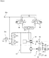
FIG. 4 is a hydraulic circuit diagram illustrating a hydraulic configuration; -
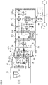
FIG. 5 is a partial cross-sectional side view illustrating a travel driving unit of a work vehicle; -
FIG. 6 is a partially enlarged cross-sectional side view illustrating an arrangement of the hydromechanical continuously variable speed transmission in the travel driving unit of the work vehicle; -
FIG. 7 is a partially enlarged cross-sectional side view illustrating the arrangement of the hydromechanical continuously variable speed transmission in the travel driving unit of the work vehicle; -
FIG. 8 is a cross-sectional view taken along line VIII-VIII illustrating an arrangement of the hydromechanical continuously variable speed transmission in the travel driving unit of the work vehicle; and -
FIG. 9 is a cross-sectional view taken along line VIIII-VIIII illustrating the arrangement of the hydromechanical continuously variable speed transmission in the travel driving unit of the work vehicle. - Now, an embodiment of the invention will be described. Hereinafter, some embodiments will be described with reference to the accompanying drawings. The embodiments and the drawings are merely examples and are not restrictive. In some drawings, the same element is denoted by the same reference numeral.
- A hydromechanical continuously variable speed transmission according to one embodiment of the present invention will be described. The hydromechanical continuously variable speed transmission is a transmission of a type of hydromechanical transmission (HMT), and is applicable to a work vehicle, for example, an agricultural tractor. As illustrated in
FIGS. 1 to 3 , the transmission of a type of HMT includes anHST 10 and aplanetary gear mechanism 11. Specifically, in the HST 10, ahydraulic pump 21 and ahydraulic motor 22 are integrated and housed in acommon HST case 23. Thehydraulic pump 21 is an axial piston pump including apump shaft 31 for transmitting power from aflywheel 16 on a side of anengine 15 in theHST case 23, acylinder block 32 fitted to thepump shaft 31 so as not to rotate relatively to thepump shaft 31, a plurality ofpump pistons 33 disposed incylinder holes 32a bored in thecylinder block 32, thepump pistons 33 being allowed to reciprocate while maintaining oil tightness, and amovable swash plate 34 that causes thepump pistons 33 to reciprocate in an axial direction. A rear end of thepump shaft 31 extends rearward through acenter section 35 having a flat plate shape. Afitting portion 31a to be fitted to a connectingportion 61a provided at the front end of apump connecting shaft 61 described later is provided at the rear end of thepump shaft 31. - The
movable swash plate 34 is linked with a speed changing unit provided in a vehicle seat, for example, a speed changing pedal, by an appropriate link mechanism. According to an amount by which the speed changing pedal is pushed, an electromagneticproportional valve 36 is driven to reciprocate thepump pistons 33, whereby the discharge amount and discharge direction of oil of thehydraulic pump 21 can be controlled. - The
hydraulic motor 22 is an axial piston motor including amotor shaft 41 supported parallel to thepump shaft 31 in theHST case 23, acylinder block 42 fitted to themotor shaft 41 so as not to rotate relatively to themotor shaft 41, a plurality ofpistons 43 disposed incylinder holes 42a bored in thecylinder block 42, thepistons 43 being allowed to reciprocate while maintaining oil tightness, and anun-movable swash plate 44 for converting the movement of thepistons 43 that extracts or contracts by the oil from thehydraulic pump 21 into rotational driving power of thecylinder block 42. The rear end of themotor shaft 41 extends rearward through thecenter section 35. Afitting portion 41a to be fitted to a connectingportion 51a provided at the front end of asun gear shaft 51 described later is provided at the rear end of themotor shaft 41. - A rear end opening of the
HST case 23 is closed by thecenter section 35 to form an oil reservoir in theHST case 23. Thehydraulic pump 21 and thehydraulic motor 22 are slidably and rotatably mounted on thecenter section 35. Although not illustrated, oil passages connecting a pair of suction and discharge ports of thehydraulic pump 21 and a pair of suction and discharge ports of thehydraulic motor 22 to form a closed circuit is provided in thecenter section 35 as in a typical configuration. - With this configuration, by pushing the speed changing pedal to tilt the
movable swash plate 34 from the neutral position by an arbitrary angle while engine power is input to thepump shaft 31, thepump pistons 33 supported in thecylinder block 32 is driven by themovable swash plate 34 to reciprocate to discharge pressurized oil, and the discharged pressurized oil is fed to thehydraulic motor 22 via the oil passage in thecenter section 35. The pressurized oil drives thepistons 43 of thehydraulic motor 22 to extend and contract to rotate thecylinder block 42, and the rotation is extracted as rotational power of themotor shaft 41. - An
oil inlet port 35a is provided on the upper end face of thecenter section 35. Oil is added from the outside to fill the inside of the closed circuit with oil. The oil supplied from theoil inlet port 35a flows into the oil passage in theHST case 23, and causes aservo piston 37 that operates themovable swash plate 34 to reciprocate according to the opening degree of the electromagneticproportional valve 36. - When the
servo piston 37 is displaced from the initial position, themovable swash plate 34 tilts to increase the stroke of thepump pistons 33. As a result, thehydraulic pump 21 works to discharge pressurized oil. A portion of the oil from theoil inlet port 35a is supplied to acharge line 35b and the oil is added to the closed circuit connecting thehydraulic pump 21 and thehydraulic motor 22. The operating pressure of theservo piston 37 and the oil charge pressure are set by acharge relief valve 35c. Excessive pressure is released from thecharge relief valve 35c to the oil reservoir in theHST case 23. - Next, the
planetary gear mechanism 11 will be described with reference toFIGS. 1 to 3 . - The
planetary gear mechanism 11 includes thesun gear shaft 51 disposed rearward of the HST 10 and disposed coaxially with themotor shaft 41, a constant-speed drivengear 52 rotatably supported by thesun gear shaft 51, aninternal gear 53 rotating integrally with the constant-speed drivengear 52, asun gear 54 formed on the outer periphery of thesun gear shaft 51 by chipping, andplanetary gears 55 meshing with thesun gear 54 and theinternal gear 53. A plurality ofplanetary gears 55 are rotatably supported by acarrier pin 57 provided on aplanetary carrier 56, and theplanetary carrier 56 has aplanetary carrier shaft 56a, which is an HMT output shaft, at the rotational center of theplanetary carrier 56. Theplanetary carrier shaft 56a has a cylindrical shape. Thedistal end 51c of thesun gear shaft 51 is inserted in the front end portion of theplanetary carrier shaft 56a via a bearing, whereby theplanetary carrier shaft 56a is supported by thesun gear shaft 51. The constant-speed drivengear 52 meshes with a constant-speed drive gear 62 provided on thepump connecting shaft 61 connected to thepump shaft 31. The rotational power of thepump connecting shaft 61 is transmitted from the constant-speed drivengear 52 to theinternal gear 53. Thereference numeral 52a denotes a boss portion integrally formed on a side surface of the constant-speed drivengear 52. An end portion of theinternal gear 53 is situated at theboss portion 52a and meshes with the teeth of theboss portion 52a, so that theinternal gear 53 is supported by theboss portion 52a so as not to relatively rotate. Theinternal gear 53 and theboss portion 52a are fixed together by a snap ring or a circlip so as not to move relatively to each other in the axial direction. - With this configuration, power from the
flywheel 16 on the side of theengine 15 is changed into rotational power of thepump shaft 31 and thepump connecting shaft 61, and the power is transmitted from the constant-speed drive gear 62 provided on thepump connecting shaft 61 to the constant-speed drivengear 52. The constant-speed drivengear 52 rotates theinternal gear 53. Meanwhile, the rotational driving power of thehydraulic motor 22 is transmitted to thesun gear shaft 51 and input to thesun gear 54. Theplanetary gears 55 meshing with thesun gear 54 and theinternal gear 53 rotate and revolve, whereby HMT power is output from theplanetary carrier shaft 56a. That is, the power from theengine 15 is transmitted to theplanetary gears 55 via thepump shaft 31, thepump connecting shaft 61, the constant-speed drive gear 62, and the constant-speed drivengear 52, and the rotational driving power of thehydraulic motor 22 is transmitted to theplanetary gears 55 via themotor shaft 41, thesun gear shaft 51, and thesun gear 54. By combining the two driving powers in theplanetary gear mechanism 11, the rotational speed of theplanetary carrier shaft 56a, which is the HMT output shaft, provided on theplanetary carrier 56 can be varied continuously, and also, a neutral state of the rotational power not being transmitted can be realized. - The
planetary gear mechanism 11 is disposed on a rear face of thecenter section 35 on the side opposite to the side on which theHST case 23 is mounted. Abearing 61b is attached to the outer periphery of the connectingportion 61a of thepump connecting shaft 61, and abearing 51b is attached to the outer periphery of the connectingportion 51a of thesun gear shaft 51. Thebearings center section 35. - The
planetary gear mechanism 11 is housed in a planetarygear support case 71. As illustrated inFIG. 3 , the planetarygear support case 71 has a shape having two spaces combined in the up-down direction, the two spaces each having a substantially circular cross-section with a portion thereof cut out. Thepump connecting shaft 61, the constant-speed drive gear 62, and the like are housed in the upper space of the planetarygear support case 71, and the rear end side of thepump connecting shaft 61 is supported by a rear wall of the planetarygear support case 71 via abearing 61c. Theplanetary gear mechanism 11 and theplanetary carrier shaft 56a, which is the HST output shaft, are housed in the lower space of the planetarygear support case 71, and the rear end side of theplanetary carrier shaft 56a is supported by the rear wall of the planetarygear support case 71 via abearing 56b. The bottom portion of the planetarygear support case 71 is cut out to form an openedcutout 71b. - As illustrated in
FIGS. 1 and3 , thecutout 71b is formed at a position, in the front-rear direction, where at least the constant-speed drivengear 52 and theinternal gear 53 are disposed. As illustrated inFIG. 3 , thecutout 71b is recessed to the upper side and the most recessed face of thecutout 71b is further in the upper side than the lowermost ends of the constant-speed drivengear 52 and theinternal gear 53. Accordingly, the constant-speed drivengear 52 and theinternal gear 53 are housed with portions thereof protruding downward beyond the lower face of the planetarygear support case 71. - As described above, the
HST case 23 housing theHST 10, thecenter section 35, and the planetarygear support case 71 housing theplanetary gear mechanism 11 constitute theHMT unit 100. - In the present embodiment, the
HMT unit 100 is fixed inside ahousing 91 of a travelingpower transmission mechanism 89 of an agricultural tractor (not illustrated). As illustrated inFIG. 5 , the travelingpower transmission mechanism 89 is a mechanism for transmitting power from theengine 15 to a traveling system including front wheels and rear wheels 4 and 4, and thehousing 91 of the travelingpower transmission mechanism 89 is connected to the rear of theengine 15 and houses various mechanisms such as a forward-reverse switching clutch 94, a front wheelacceleration switching clutch 95, a three-stageauxiliary transmission mechanism 96, a PTO clutch 97, aPTO transmission mechanism 98, and adifferential gear 99. - The
housing 91 of the travelingpower transmission mechanism 89 includes afront housing 91a, anintermediate housing 91b, a rear housing 91c, and adifferential housing 91d connected to each other. The inside of thefront housing 91a is partitioned into afirst chamber 92A opened to the side of theengine 15 and asecond chamber 92B opened to the side of the travelingpower transmission mechanism 89. The rear face of theengine 15 and thefront housing 91a form thefirst chamber 92A. Thefirst chamber 92A houses theHST case 23 and thecenter section 35 of theHMT unit 100. A mountingportion 91e, described later, of thefront housing 91a, the rear face of thecenter section 35, and theintermediate housing 91b form thesecond chamber 92B. Thesecond chamber 92B houses the planetarygear support case 71 and a frontwheel drive shaft 93 of theHMT unit 100. - The
housing 91 also has athird chamber 92C housing the forward-reverse switching clutch 94 and the front wheelacceleration switching clutch 95, and afourth chamber 92D housing theauxiliary transmission mechanism 96, the PTO clutch 97, thePTO transmission mechanism 98, and thedifferential gear 99. Thethird chamber 92C is mainly configured with the rear housing 91c, and thefourth chamber 92D is mainly configured with thedifferential housing 91d. - The traveling
power transmission mechanism 89 transmits power of the traveling system and a work system. For the traveling system, the driving power from theplanetary carrier shaft 56a, which is the HMT output shaft, is transmitted to theauxiliary transmission mechanism 96 via the forward-reverse switching clutch 94. The power transmitted to theauxiliary transmission mechanism 96 is transmitted from afinal gear 111 housed in afinal gear case 110 to the rear wheels 4 and 4 via thedifferential gear 99. - For the traveling system, the power transmitted to the
auxiliary transmission mechanism 96 is transmitted to the frontwheel drive shaft 93. The front wheelacceleration switching clutch 95 is provided at midway of the frontwheel drive shaft 93. - In the present embodiment, the
HMT unit 100 is fixed to thefront housing 91a of thehousing 91. Thecenter section 35 of theHMT unit 100 has a mountingface 35d for fixing thefront housing 91a. The mountingface 35d is provided on the rear face of thecenter section 35 so as to surround the outer circumference of the mountingface 71a of the planetarygear support case 71 along the outer rim of thecenter section 35. The mountingface 35d is provided with a plurality of holes to whichbolts 38 and astud bolt 38a described later are inserted. - As illustrated in
FIGS. 6 to 8 , thefront housing 91a has a frontend flange face 91a(1) for connecting thefront housing 91a to theengine 15 and a rearend flange face 91a(2) for connecting thefront housing 91a to theintermediate housing 91b. The mountingportion 91e for demarcating thefirst chamber 92A from thesecond chamber 92B is provided at a place further to the inner side of thehousing 91 along the rotational axis than the rearend flange face 91a(2). The mountingportion 91e is provided to protrude from the inner wall face of the rear end of thefront housing 91a toward the rotational axis, and has screw holes at places each corresponding to the respective one of bolt insertion holes provided in the mountingface 35d of thecenter section 35. The mountingface 35d of thecenter section 35 is placed on the front face of the mountingportion 91e, and fixed by thebolts 38 and the stud bolt andnut HMT unit 100 is fixed to thefront housing 91a. - As illustrated in
FIGS. 6 and8 , thebolts 38 as fixing members are put through the frontend flange face 91a(1) from the front side (side of the flywheel) toward the rear side (side of the planetary gear support case 71) to penetrate thecenter section 35 that has been brought into contact with the front face of the mountingportion 91e and screwed into the mountingportion 91e. - As illustrated in
FIG. 9 , for the bolt insertion hole provided at a place where the front face of thecenter section 35 is blocked by theservo piston housing 23a of theHST case 23, the tip of thestud bolt 38a screwed into the mountingportion 91e is inserted through the bolt insertion hole, and thenut 38b is inserted through anopening 91f provided in the peripheral wall of thefront housing 91a and then screwed onto the tip of thestud bolt 38a. Theopening 91f is used for passing the wiring of the electromagneticproportional valve 36 and a hydraulic oil supply tube for the closed circuit to the inside of thefront housing 91a. - With this configuration, the
HMT unit 100 will become detachable from thefront housing 91a by only separating theengine 15 from the frontend flange face 91a(1) of thefront housing 91a with thefront housing 91a still coupled to theintermediate housing 91b. This makes maintenance work of theHST 10 as well as the maintenance work of theplanetary gear mechanism 11 easy. - In addition, when fixing the
HMT unit 100 in thefront housing 91a, theplanetary gear mechanism 11 is disposed on the side of thesecond chamber 92B with the mountingface 35d of thecenter section 35 in close contact with the entire circumference of the mountingportion 91e. That is, making thecenter section 35 in close contact with the entire circumference of the mountingportion 91e keeps an oil-tight state, and thus thefirst chamber 92A can be used as a dry chamber and thesecond chamber 92B can be used as an oil reservoir. - A single drive shaft constituting the traveling
power transmission mechanism 89 is disposed in thesecond chamber 92B of thehousing 91. In the present embodiment, the frontwheel drive shaft 93 that drives the front wheel by the traveling power is disposed. - The bottom portion, which is a portion opposing the front
wheel drive shaft 93, of the planetarygear support case 71 is cut out to form thecutout 71b to prevent contact between the planetarygear support case 71 and the frontwheel drive shaft 93. - When completely covering the constant-speed driven
gear 52 and theinternal gear 53 with the planetarygear support case 71 without providing thecutout 71b, the bottom face of the planetarygear support case 71 inevitably protrudes downward. In contrast, by opening the bottom portion by forming such acutout 71b that will not affect the strength of the planetarygear support case 71, the planetarygear support case 71 can be downsized, and thus the planetarygear support case 71 can be disposed close to the frontwheel drive shaft 93. - The supplied lubricating oil in the
second chamber 92B is efficiently supplied to theplanetary gear mechanism 11 from thecutout 71b. That is, the inside of thesecond chamber 92B is supplied with lubricating oil, and the lower portions of the constant-speed drivengear 52 and theinternal gear 53 of theplanetary gear mechanism 11 are in contact with the lubricating oil. During traveling, the portions in contact with the lubricating oil scoop up the oil to improve lubricity to the lubricated portions. - As described above, the hydromechanical continuously variable speed transmission that changes the speed of output rotation of the
engine 15 is a transmission of a type of HMT (hydromechanical transmission) and includes: theHST 10 in which thehydraulic pump 21 and thehydraulic motor 22 are housed in theHST case 23, and including thecenter section 35 mounted on theHST case 23 and fluidly connecting thehydraulic pump 21 and thehydraulic motor 22; and theplanetary gear mechanism 11 configured to output, in combination with theHST 10, continuously varied speed to the travelingpower transmission mechanism 89, where theplanetary gear mechanism 11 is housed in the planetarygear support case 71 mounted on a face of thecenter section 35 to form theHMT unit 100, the face being on the side opposite to the side on which theHST case 23 is mounted, and theHMT unit 100 is further provided with thehousing mounting face 35d for fixing theHMT unit 100 to thehousing 91 of the travelingpower transmission mechanism 89, thehousing mounting face 35d being provided on thecenter section 35 so as to surround the outer circumference of the mountingface 71a on which the planetarygear support case 71 is mounted. - With the above configuration, the
planetary gear mechanism 11 in the assembled state can be housed in the planetarygear support case 71 and fixed to the rear face of thecenter section 35, which improves efficiency of assembly. - Furthermore, it may be configured that the mounting
portion 91e for partitioning the inside of thehousing 91 into thefirst chamber 92A opened toward the side of theengine 15 and thesecond chamber 92B opened toward the side of the travelingpower transmission mechanism 89 is provided on the inner wall face of thehousing 91 to protrude inward, and when theHMT unit 100 is fixed to thehousing 91, theplanetary gear mechanism 11 is positioned on the side of thesecond chamber 92B while thehousing mounting face 35d of thecenter section 35 is in close contact with the entire circumference of the mountingportion 91e. The upper portion of the planetarygear support case 71 houses only the constant-speed drive gear 62, so that the upper portion can be formed to have a small volume. This allows the mountingportion 91e to be disposed in a space behind thecenter section 35, the space being in the opposite side of the mounting face to which theHST case 23 is mounted. This allows theHMT unit 100 to be housed inside thehousing 91 of the travelingpower transmission mechanism 89 without making thehousing 91 large. - With this configuration, when fixing the
HMT unit 100 to thehousing 91, theplanetary gear mechanism 11 can be lubricated with thecenter section 35 holding the lubricating oil for the travelingpower transmission mechanism 89 in thehousing 91. - Furthermore, the front
wheel drive shaft 93 constituting the travelingpower transmission mechanism 89 may be disposed in thesecond chamber 92B of thehousing 91, and the lower portion of the planetarygear support case 71 opposing the frontwheel drive shaft 93 may be cut out. - With this configuration, the planetary
gear support case 71 of theHMT unit 100 can be downsized, and the planetarygear support case 71 can be disposed close to the frontwheel drive shaft 93 in thesecond chamber 92B of thehousing 91 without interfering with the frontwheel drive shaft 93. Furthermore, lubricating oil can be efficiently supplied from thecutout 71b to theplanetary gear mechanism 11. - The above description relates to specific examples according to the present invention, and various modifications can be made without departing from the spirit of the present invention. The appended claims are intended to include such applications within the true scope and spirit of the present invention.
- Thus, all the embodiments disclosed in the present application should be construed as illustrative and not restrictive. The scope of the present invention is recited in the following claims rather than in the above description, and any modification that falls within the scope equivalent to the meaning of the claims should be included in the scope of the present invention.
Claims (3)
- A hydromechanical continuously variable speed transmission that changes a speed of output rotation of an engine, the hydromechanical continuously variable speed transmission comprising: an HST in which a hydraulic pump and a hydraulic motor are housed in an HST case, and including a center section mounted on the HST case and fluidly connecting the hydraulic pump and the hydraulic motor; and a planetary gear mechanism configured to output, in combination with the HST, continuously varied speed to a traveling power transmission mechanism, whereinthe planetary gear mechanism is housed in a planetary gear support case mounted on a face of the center section to form an HMT unit, the face being on a side opposite to a side on which the HST case is mounted, andthe HMT unit is further provided with a housing mounting face for fixing the HMT unit to a housing of the traveling power transmission mechanism, the housing mounting face being provided on the center section so as to surround an outer circumference of a mounting face on which the planetary gear support case is mounted.
- The hydromechanical continuously variable speed transmission according to claim 1, wherein
a mounting portion for partitioning an inside of the housing into a first chamber opened toward a side of the engine and a second chamber opened toward a side of the traveling power transmission mechanism is provided on an inner wall face of the housing to protrude inward, and when the HMT unit is fixed to the housing, the planetary gear mechanism is positioned on a side of the second chamber while the housing mounting face of the center section is in close contact with an entire circumference of the mounting portion. - The hydromechanical continuously variable speed transmission according to claim 2, whereina single drive shaft constituting the traveling power transmission mechanism is disposed in the second chamber of the housing, anda portion, opposing the drive shaft, of the planetary gear support case is cut out.
Applications Claiming Priority (1)
| Application Number | Priority Date | Filing Date | Title |
|---|---|---|---|
| JP2021060436A JP2022156638A (en) | 2021-03-31 | 2021-03-31 | Hydraulic/mechanical stepless gear shift device |
Publications (1)
| Publication Number | Publication Date |
|---|---|
| EP4067698A1 true EP4067698A1 (en) | 2022-10-05 |
Family
ID=80930105
Family Applications (1)
| Application Number | Title | Priority Date | Filing Date |
|---|---|---|---|
| EP22163629.3A Withdrawn EP4067698A1 (en) | 2021-03-31 | 2022-03-22 | Hydromechanical continuously variable speed transmission |
Country Status (4)
| Country | Link |
|---|---|
| US (1) | US11644091B2 (en) |
| EP (1) | EP4067698A1 (en) |
| JP (1) | JP2022156638A (en) |
| CN (1) | CN115143255A (en) |
Families Citing this family (2)
| Publication number | Priority date | Publication date | Assignee | Title |
|---|---|---|---|---|
| US11994201B2 (en) * | 2020-12-28 | 2024-05-28 | Kubota Corporation | Power transmission device for work vehicle |
| JP7774544B2 (en) * | 2022-11-17 | 2025-11-21 | 株式会社クボタ | Solenoid valve control device and work vehicle |
Citations (5)
| Publication number | Priority date | Publication date | Assignee | Title |
|---|---|---|---|---|
| US2227647A (en) * | 1938-06-27 | 1941-01-07 | Charles A Holman | Hydraulic power transmission mechanism |
| US2687049A (en) * | 1950-12-14 | 1954-08-24 | Ebert Heinrich | Axial piston fluid transmission |
| JP2001315538A (en) * | 2000-05-09 | 2001-11-13 | Ishikawajima Shibaura Mach Co Ltd | Hydraulic-mechanical continuously variable transmission |
| US6530855B1 (en) * | 1998-11-24 | 2003-03-11 | Folsom Technologies, Inc. | Parallel hydromechanical underdrive transmission |
| JP2007230554A (en) * | 2002-01-18 | 2007-09-13 | Kanzaki Kokyukoki Mfg Co Ltd | Working vehicle |
Family Cites Families (5)
| Publication number | Priority date | Publication date | Assignee | Title |
|---|---|---|---|---|
| CH443925A (en) * | 1965-08-20 | 1967-09-15 | Agie Ag Ind Elektronik | Hydraulic device on an electrical discharge machine for the storage and controlled feed of a tool electrode |
| JP2010076748A (en) | 2008-08-29 | 2010-04-08 | Kanzaki Kokyukoki Mfg Co Ltd | Traveling system transmission structure of vehicle |
| JP6843338B2 (en) | 2016-07-05 | 2021-03-17 | 株式会社 神崎高級工機製作所 | HMT unit and HMT structure |
| US10125848B2 (en) * | 2016-07-19 | 2018-11-13 | Deere & Company | Variator for work vehicle drivetrain |
| US10271478B2 (en) * | 2017-01-11 | 2019-04-30 | Cnh Industrial America Llc | Hydromechanical transmission system for a header of an agricultural harvester |
-
2021
- 2021-03-31 JP JP2021060436A patent/JP2022156638A/en active Pending
-
2022
- 2022-02-16 CN CN202210141084.5A patent/CN115143255A/en active Pending
- 2022-03-22 EP EP22163629.3A patent/EP4067698A1/en not_active Withdrawn
- 2022-03-31 US US17/709,818 patent/US11644091B2/en active Active
Patent Citations (6)
| Publication number | Priority date | Publication date | Assignee | Title |
|---|---|---|---|---|
| US2227647A (en) * | 1938-06-27 | 1941-01-07 | Charles A Holman | Hydraulic power transmission mechanism |
| US2687049A (en) * | 1950-12-14 | 1954-08-24 | Ebert Heinrich | Axial piston fluid transmission |
| US6530855B1 (en) * | 1998-11-24 | 2003-03-11 | Folsom Technologies, Inc. | Parallel hydromechanical underdrive transmission |
| JP2001315538A (en) * | 2000-05-09 | 2001-11-13 | Ishikawajima Shibaura Mach Co Ltd | Hydraulic-mechanical continuously variable transmission |
| JP4162359B2 (en) | 2000-05-09 | 2008-10-08 | 株式会社Ihiシバウラ | Hydraulic and mechanical continuously variable transmission |
| JP2007230554A (en) * | 2002-01-18 | 2007-09-13 | Kanzaki Kokyukoki Mfg Co Ltd | Working vehicle |
Also Published As
| Publication number | Publication date |
|---|---|
| US11644091B2 (en) | 2023-05-09 |
| JP2022156638A (en) | 2022-10-14 |
| US20220316570A1 (en) | 2022-10-06 |
| CN115143255A (en) | 2022-10-04 |
Similar Documents
| Publication | Publication Date | Title |
|---|---|---|
| US4870820A (en) | HST (hydro-static-transmission) system driving speed changing apparatus | |
| US6884195B2 (en) | Hydrostatic transaxle | |
| US7357745B2 (en) | Travel working machine | |
| JPH0752666A (en) | Hydraulic transmission | |
| KR20020093040A (en) | Hydromechanical speed-change device and vehicle having speed change device mounted thereon | |
| KR102372142B1 (en) | Transmission of agriculture vehicle | |
| JP4492989B2 (en) | Shifting operation mechanism | |
| US11644091B2 (en) | Hydromechanical continuously variable speed transmission | |
| GB2373773A (en) | Frameless working vehicle including a hydrostatic transmission | |
| US20090145124A1 (en) | Hydraulic Transaxle | |
| US10641389B2 (en) | Actuator unit for controlling hydraulic pump | |
| CN111878558B (en) | HMT unit and HMT structure | |
| EP1348588B1 (en) | Axle driving apparatus | |
| KR100956704B1 (en) | Power Train of Agricultural Vehicles | |
| JP3016057B2 (en) | transmission | |
| JPH0313588Y2 (en) | ||
| JP4217549B2 (en) | Hydraulic-mechanical transmission | |
| JP7307937B2 (en) | HST and transmission | |
| US6569049B1 (en) | Radial piston hydromechanical continuously variable transmission | |
| EP0966363A1 (en) | Axle driving system | |
| JP4180139B2 (en) | Axle drive | |
| JP2002205561A (en) | Hydrostatic continuously variable transmission for traveling | |
| JP4366275B2 (en) | Work vehicle | |
| US20240328496A1 (en) | Hmt structure and hst unit | |
| EP2402630B1 (en) | Working vehicle |
Legal Events
| Date | Code | Title | Description |
|---|---|---|---|
| PUAI | Public reference made under article 153(3) epc to a published international application that has entered the european phase |
Free format text: ORIGINAL CODE: 0009012 |
|
| STAA | Information on the status of an ep patent application or granted ep patent |
Free format text: STATUS: THE APPLICATION HAS BEEN PUBLISHED |
|
| AK | Designated contracting states |
Kind code of ref document: A1 Designated state(s): AL AT BE BG CH CY CZ DE DK EE ES FI FR GB GR HR HU IE IS IT LI LT LU LV MC MK MT NL NO PL PT RO RS SE SI SK SM TR |
|
| STAA | Information on the status of an ep patent application or granted ep patent |
Free format text: STATUS: REQUEST FOR EXAMINATION WAS MADE |
|
| 17P | Request for examination filed |
Effective date: 20230315 |
|
| RBV | Designated contracting states (corrected) |
Designated state(s): AL AT BE BG CH CY CZ DE DK EE ES FI FR GB GR HR HU IE IS IT LI LT LU LV MC MK MT NL NO PL PT RO RS SE SI SK SM TR |
|
| GRAP | Despatch of communication of intention to grant a patent |
Free format text: ORIGINAL CODE: EPIDOSNIGR1 |
|
| STAA | Information on the status of an ep patent application or granted ep patent |
Free format text: STATUS: GRANT OF PATENT IS INTENDED |
|
| RIC1 | Information provided on ipc code assigned before grant |
Ipc: F16H 57/021 20120101ALI20231018BHEP Ipc: F16H 47/04 20060101AFI20231018BHEP |
|
| INTG | Intention to grant announced |
Effective date: 20231103 |
|
| STAA | Information on the status of an ep patent application or granted ep patent |
Free format text: STATUS: THE APPLICATION IS DEEMED TO BE WITHDRAWN |
|
| 18D | Application deemed to be withdrawn |
Effective date: 20240305 |