EP4067690A1 - Mount bushing - Google Patents
Mount bushing Download PDFInfo
- Publication number
- EP4067690A1 EP4067690A1 EP22160545.4A EP22160545A EP4067690A1 EP 4067690 A1 EP4067690 A1 EP 4067690A1 EP 22160545 A EP22160545 A EP 22160545A EP 4067690 A1 EP4067690 A1 EP 4067690A1
- Authority
- EP
- European Patent Office
- Prior art keywords
- mass
- mount bushing
- present disclosure
- mount
- outer tube
- Prior art date
- Legal status (The legal status is an assumption and is not a legal conclusion. Google has not performed a legal analysis and makes no representation as to the accuracy of the status listed.)
- Granted
Links
Images


Classifications
-
- F—MECHANICAL ENGINEERING; LIGHTING; HEATING; WEAPONS; BLASTING
- F16—ENGINEERING ELEMENTS AND UNITS; GENERAL MEASURES FOR PRODUCING AND MAINTAINING EFFECTIVE FUNCTIONING OF MACHINES OR INSTALLATIONS; THERMAL INSULATION IN GENERAL
- F16F—SPRINGS; SHOCK-ABSORBERS; MEANS FOR DAMPING VIBRATION
- F16F1/00—Springs
- F16F1/36—Springs made of rubber or other material having high internal friction, e.g. thermoplastic elastomers
- F16F1/38—Springs made of rubber or other material having high internal friction, e.g. thermoplastic elastomers with a sleeve of elastic material between a rigid outer sleeve and a rigid inner sleeve or pin, i.e. bushing-type
- F16F1/3828—End stop features or buffering
-
- B—PERFORMING OPERATIONS; TRANSPORTING
- B60—VEHICLES IN GENERAL
- B60G—VEHICLE SUSPENSION ARRANGEMENTS
- B60G21/00—Interconnection systems for two or more resiliently-suspended wheels, e.g. for stabilising a vehicle body with respect to acceleration, deceleration or centrifugal forces
- B60G21/02—Interconnection systems for two or more resiliently-suspended wheels, e.g. for stabilising a vehicle body with respect to acceleration, deceleration or centrifugal forces permanently interconnected
- B60G21/04—Interconnection systems for two or more resiliently-suspended wheels, e.g. for stabilising a vehicle body with respect to acceleration, deceleration or centrifugal forces permanently interconnected mechanically
- B60G21/05—Interconnection systems for two or more resiliently-suspended wheels, e.g. for stabilising a vehicle body with respect to acceleration, deceleration or centrifugal forces permanently interconnected mechanically between wheels on the same axle but on different sides of the vehicle, i.e. the left and right wheel suspensions being interconnected
- B60G21/055—Stabiliser bars
- B60G21/0551—Mounting means therefor
-
- B—PERFORMING OPERATIONS; TRANSPORTING
- B60—VEHICLES IN GENERAL
- B60K—ARRANGEMENT OR MOUNTING OF PROPULSION UNITS OR OF TRANSMISSIONS IN VEHICLES; ARRANGEMENT OR MOUNTING OF PLURAL DIVERSE PRIME-MOVERS IN VEHICLES; AUXILIARY DRIVES FOR VEHICLES; INSTRUMENTATION OR DASHBOARDS FOR VEHICLES; ARRANGEMENTS IN CONNECTION WITH COOLING, AIR INTAKE, GAS EXHAUST OR FUEL SUPPLY OF PROPULSION UNITS IN VEHICLES
- B60K5/00—Arrangement or mounting of internal-combustion or jet-propulsion units
- B60K5/12—Arrangement of engine supports
- B60K5/1208—Resilient supports
-
- F—MECHANICAL ENGINEERING; LIGHTING; HEATING; WEAPONS; BLASTING
- F16—ENGINEERING ELEMENTS AND UNITS; GENERAL MEASURES FOR PRODUCING AND MAINTAINING EFFECTIVE FUNCTIONING OF MACHINES OR INSTALLATIONS; THERMAL INSULATION IN GENERAL
- F16F—SPRINGS; SHOCK-ABSORBERS; MEANS FOR DAMPING VIBRATION
- F16F1/00—Springs
- F16F1/36—Springs made of rubber or other material having high internal friction, e.g. thermoplastic elastomers
- F16F1/371—Springs made of rubber or other material having high internal friction, e.g. thermoplastic elastomers characterised by inserts or auxiliary extension or exterior elements, e.g. for rigidification
-
- B—PERFORMING OPERATIONS; TRANSPORTING
- B60—VEHICLES IN GENERAL
- B60K—ARRANGEMENT OR MOUNTING OF PROPULSION UNITS OR OF TRANSMISSIONS IN VEHICLES; ARRANGEMENT OR MOUNTING OF PLURAL DIVERSE PRIME-MOVERS IN VEHICLES; AUXILIARY DRIVES FOR VEHICLES; INSTRUMENTATION OR DASHBOARDS FOR VEHICLES; ARRANGEMENTS IN CONNECTION WITH COOLING, AIR INTAKE, GAS EXHAUST OR FUEL SUPPLY OF PROPULSION UNITS IN VEHICLES
- B60K5/00—Arrangement or mounting of internal-combustion or jet-propulsion units
- B60K5/12—Arrangement of engine supports
- B60K5/1291—Supports comprising stoppers
-
- F—MECHANICAL ENGINEERING; LIGHTING; HEATING; WEAPONS; BLASTING
- F16—ENGINEERING ELEMENTS AND UNITS; GENERAL MEASURES FOR PRODUCING AND MAINTAINING EFFECTIVE FUNCTIONING OF MACHINES OR INSTALLATIONS; THERMAL INSULATION IN GENERAL
- F16C—SHAFTS; FLEXIBLE SHAFTS; ELEMENTS OR CRANKSHAFT MECHANISMS; ROTARY BODIES OTHER THAN GEARING ELEMENTS; BEARINGS
- F16C17/00—Sliding-contact bearings for exclusively rotary movement
- F16C17/10—Sliding-contact bearings for exclusively rotary movement for both radial and axial load
-
- F—MECHANICAL ENGINEERING; LIGHTING; HEATING; WEAPONS; BLASTING
- F16—ENGINEERING ELEMENTS AND UNITS; GENERAL MEASURES FOR PRODUCING AND MAINTAINING EFFECTIVE FUNCTIONING OF MACHINES OR INSTALLATIONS; THERMAL INSULATION IN GENERAL
- F16F—SPRINGS; SHOCK-ABSORBERS; MEANS FOR DAMPING VIBRATION
- F16F1/00—Springs
- F16F1/36—Springs made of rubber or other material having high internal friction, e.g. thermoplastic elastomers
- F16F1/38—Springs made of rubber or other material having high internal friction, e.g. thermoplastic elastomers with a sleeve of elastic material between a rigid outer sleeve and a rigid inner sleeve or pin, i.e. bushing-type
- F16F1/3863—Springs made of rubber or other material having high internal friction, e.g. thermoplastic elastomers with a sleeve of elastic material between a rigid outer sleeve and a rigid inner sleeve or pin, i.e. bushing-type characterised by the rigid sleeves or pin, e.g. of non-circular cross-section
-
- F—MECHANICAL ENGINEERING; LIGHTING; HEATING; WEAPONS; BLASTING
- F16—ENGINEERING ELEMENTS AND UNITS; GENERAL MEASURES FOR PRODUCING AND MAINTAINING EFFECTIVE FUNCTIONING OF MACHINES OR INSTALLATIONS; THERMAL INSULATION IN GENERAL
- F16F—SPRINGS; SHOCK-ABSORBERS; MEANS FOR DAMPING VIBRATION
- F16F7/00—Vibration-dampers; Shock-absorbers
- F16F7/10—Vibration-dampers; Shock-absorbers using inertia effect
- F16F7/104—Vibration-dampers; Shock-absorbers using inertia effect the inertia member being resiliently mounted
- F16F7/108—Vibration-dampers; Shock-absorbers using inertia effect the inertia member being resiliently mounted on plastics springs
-
- B—PERFORMING OPERATIONS; TRANSPORTING
- B60—VEHICLES IN GENERAL
- B60G—VEHICLE SUSPENSION ARRANGEMENTS
- B60G2204/00—Indexing codes related to suspensions per se or to auxiliary parts
- B60G2204/10—Mounting of suspension elements
- B60G2204/12—Mounting of springs or dampers
- B60G2204/122—Mounting of torsion springs
- B60G2204/1222—Middle mounts of stabiliser on vehicle body or chassis
-
- B—PERFORMING OPERATIONS; TRANSPORTING
- B60—VEHICLES IN GENERAL
- B60G—VEHICLE SUSPENSION ARRANGEMENTS
- B60G2204/00—Indexing codes related to suspensions per se or to auxiliary parts
- B60G2204/40—Auxiliary suspension parts; Adjustment of suspensions
- B60G2204/41—Elastic mounts, e.g. bushings
-
- B—PERFORMING OPERATIONS; TRANSPORTING
- B60—VEHICLES IN GENERAL
- B60Y—INDEXING SCHEME RELATING TO ASPECTS CROSS-CUTTING VEHICLE TECHNOLOGY
- B60Y2200/00—Type of vehicle
- B60Y2200/90—Vehicles comprising electric prime movers
- B60Y2200/91—Electric vehicles
-
- B—PERFORMING OPERATIONS; TRANSPORTING
- B60—VEHICLES IN GENERAL
- B60Y—INDEXING SCHEME RELATING TO ASPECTS CROSS-CUTTING VEHICLE TECHNOLOGY
- B60Y2306/00—Other features of vehicle sub-units
- B60Y2306/09—Reducing noise
Definitions
- the present disclosure relates generally to a mount bushing for a vehicle and, more particularly, to a mount bushing configured to minimize frequency shifting according to difference of dynamic properties applied by a load input to a mount.
- a mount bushing is used in a vehicle, and generally, has an outer tube, an inner tube, and a rubber part provided between the outer tube and the inner tube, and a mass is provided in the rubber part to reinforce the rigidity of the mount bushing.
- Patent Document 1 KR10-1124595 B1
- the present disclosure has been made keeping in mind the above problem occurring in the related art, and the present disclosure is intended to provide a mount bushing configured to improve noise, vibration, harshness by minimizing shifting of frequency caused by a mass of the mount bushing even when a load in a main direction is applied to the mount bushing according to driving conditions of a vehicle and thus dynamic properties are changed according to a load size.
- a mount bushing including: an outer tube; an inner tube provided in the outer tube; a rubber part provided between the outer tube and the inner tube; a tubular mass provided in the rubber part and having an opening formed by partially penetrating an outer circumferential surface thereof; and a stopper shaped to protrude outward from the inner tube to pass through the opening of the tubular mass, wherein the mount bushing is configured to minimize mutual interference between the mass and the stopper in deformation due to an external force.
- the rubber part may include: a center portion covering the mass, a first connecting portion connecting the center portion to the outer tube, and a second connecting portion connecting the center portion to the inner tube.
- the mass may include: an auxiliary mass attached to the outer circumferential surface thereof.
- the outer tube may include: a buffering rubber part provided at a location corresponding to the stopper.
- the mass and the stopper constituting the mount bushing are separated from each other as much as possible, so that peak frequency is maintained constant even when an external load varies. Therefore, noise, vibration, and harshness are prevented.
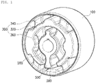
- FIG. 1 is a perspective view showing a mount bushing according to an embodiment of the present disclosure.
- FIG. 2 is an exploded-perspective view showing the mount bushing according to the embodiment of the present disclosure.
- FIG. 3 is an inner structure view showing the mount bushing according to the embodiment of the present disclosure.
- FIG. 4 is a front view showing the mount bushing according to the embodiment of the present disclosure.
- FIG. 5 is a view showing an example of a mass of the mount bushing according to the embodiment of the present disclosure.
- FIG. 6 is a view showing another example of the mass of the mount bushing according to the embodiment of the present disclosure.
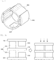
- FIG. 7A is a state view showing deformation due to a load in a current mount bushing.
- FIG. 7B is a state view showing deformation due to a load in the mount bushing according to the present disclosure.
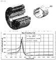
- FIG. 8A is a frequency deformation graph of the current mount bushing.
- FIG. 8B is a frequency deformation graph of the mount bushing according to the present disclosure.
- the mount bushing according to the present disclosure includes an outer tube 100, an inner tube 200, a rubber part 300, a mass 400, and a stopper 500.
- the mount bushing of the present disclosure is configured to reduce mutual interference between the mass 400 and the stopper 500 when an external load is applied, thereby minimizing frequency shifting to reduce vehicle noise, vibration, and harshness.
- the outer tube 100 corresponds to an outer form of the mount bushing, has a tubular shape, and may have a shape in which semicircular shapes are coupled to each other.
- the inner tube 200 is provided inside the outer tube 100 in a tubular shape.
- the rubber part 300 is provided between the outer tube 100 and the inner tube 200 and absorbs impacts and vibrations due to elasticity.
- the rubber part 300 includes a ring-shaped center portion 320 covering the mass 400 therein, a plurality of first connecting portions 340 radially arranged to connect the center portion 320 to the outer tube 100, and a plurality of second connecting portions 360 radially arranged to connect the center portion 320 to the inner tube 200.
- Each of the first connecting portions 340 may consist of a leg portion protruding outward from the center portion 320 at an interval and an outmost portion shaped to correspond to an inner circumferential surface of the outer tube 100.
- the second connecting portion 360 may consist of a leg portion protruding inward from the center portion 320 at an interval and an innermost portion shaped to correspond to an outer circumferential surface of the inner tube 200
- the mass 400 is a portion provided in a tubular shape in the rubber part 300 and reinforcing the rigidity of the mount bushing.
- the mass 400 has an opening 420 formed by penetrating a part of an outer circumferential surface thereof.
- the opening 420 is a hall penetrating the outer circumferential surface in the tubular shape, and thus providing a moving path of the stopper 500, which will be described later.
- the mass 400 may be conventionally used with a 'C' shape.
- the mount bushing of the present disclosure is reinforced in the rigidity with a leg connected to a first end of the mass in order to prevent resonance thereof from being generated, and a leg may be connected to a second end of the mass as shown in FIG. 6 .
- the mass 400 may include an auxiliary mass 440, which is attached to the outer circumferential surface thereof by welding, thereby increasing the weight of the mass.
- the mass 400 was produced by a pressing process considering a manufacturing cost in the present disclosure.
- the stopper 500 is shaped to protrude outward from the inner tube 200 to pass through the opening 420 of the mass 400.
- the stopper 500 is moved while passing through the opening 420 of the mass 400 without direct contact with the mass 400 so that mutual interference between the stopper 500 and the mass 400 may be minimized, thereby minimizing amplification of frequency applied to the mass 400 to which a dynamic load is applied.
- the outer tube 100 includes a buffering rubber part 380 at a location corresponding to the stopper 500 to absorb an impact of the stopper 500.
- FIGS. 7A to 8B are views showing comparison of a difference between the current mount bushing and the mount bushing of the present disclosure according to loads thereof.
- FIG. 7A when a load is applied to the current mount bushing, the stopper 500 is brought in close contact with the mass 400, so that the mass 400 is influenced by the load.
- FIG. 7B when a load is applied to the mount bushing of the present disclosure, the stopper 500 allows the load not to be applied to the mass 400.
- the mount bushing of the present disclosure is configured to separate the mass from the stopper as much as possible, so that even when a Z-directional load is applied, there is an advantage of reducing NVH by reducing frequency shifting.
Landscapes
- Engineering & Computer Science (AREA)
- General Engineering & Computer Science (AREA)
- Mechanical Engineering (AREA)
- Chemical & Material Sciences (AREA)
- Combustion & Propulsion (AREA)
- Transportation (AREA)
- Springs (AREA)
- Vibration Prevention Devices (AREA)
Abstract
Description
- The present application claims priority to
Korean Patent Application No. 10-2021-0030260, filed March 08, 2021 - The present disclosure relates generally to a mount bushing for a vehicle and, more particularly, to a mount bushing configured to minimize frequency shifting according to difference of dynamic properties applied by a load input to a mount.
- A mount bushing is used in a vehicle, and generally, has an outer tube, an inner tube, and a rubber part provided between the outer tube and the inner tube, and a mass is provided in the rubber part to reinforce the rigidity of the mount bushing.
- Specifically, in driving of an electric vehicle, as a Z-directional load is input to a mount by engine torque in response to a step degree of an accelerator, dynamic properties are also changed, and frequency of a first resonance around 500Hz caused by the mass is shifted backward and the dynamic properties are also amplified, so that there is a problem in that the frequency shifting adversely affects vehicle noise, vibration, and harshness.
- (Patent Document 1)
KR10-1124595 B1 - Accordingly, the present disclosure has been made keeping in mind the above problem occurring in the related art, and the present disclosure is intended to provide a mount bushing configured to improve noise, vibration, harshness by minimizing shifting of frequency caused by a mass of the mount bushing even when a load in a main direction is applied to the mount bushing according to driving conditions of a vehicle and thus dynamic properties are changed according to a load size.
- In order to achieve the above objective, according to one aspect of the present disclosure, there is provided a mount bushing including: an outer tube; an inner tube provided in the outer tube; a rubber part provided between the outer tube and the inner tube; a tubular mass provided in the rubber part and having an opening formed by partially penetrating an outer circumferential surface thereof; and a stopper shaped to protrude outward from the inner tube to pass through the opening of the tubular mass, wherein the mount bushing is configured to minimize mutual interference between the mass and the stopper in deformation due to an external force.
- The rubber part may include: a center portion covering the mass, a first connecting portion connecting the center portion to the outer tube, and a second connecting portion connecting the center portion to the inner tube.
- The mass may include: an auxiliary mass attached to the outer circumferential surface thereof.
- The outer tube may include: a buffering rubber part provided at a location corresponding to the stopper.
- According to the above solution, an effect can be expected as follows.
- The mass and the stopper constituting the mount bushing are separated from each other as much as possible, so that peak frequency is maintained constant even when an external load varies. Therefore, noise, vibration, and harshness are prevented.
- The above and other objectives, features, and other advantages of the present disclosure will be more clearly understood from the following detailed description when taken in conjunction with the accompanying drawings, in which:
-
FIG. 1 is a perspective view showing a mount bushing according to an embodiment of the present disclosure; -
FIG. 2 is an exploded-perspective view showing the mount bushing according to the embodiment of the present disclosure; -
FIG. 3 is an inner structure view showing the mount bushing according to the embodiment of the present disclosure; -
FIG. 4 is a front view showing the mount bushing according to the embodiment of the present disclosure; -
FIG. 5 is a view showing an example of a mass of the mount bushing according to the embodiment of the present disclosure; -
FIG. 6 is a view showing another example of the mass of the mount bushing according to the embodiment of the present disclosure; -
FIG. 7A is a state view showing deformation due to a load in a current mount bushing; -
FIG. 7B is a state view showing deformation due to a load in the mount bushing according to the present disclosure; -
FIG. 8A is a frequency deformation graph of the current mount bushing; and -
FIG. 8B is a frequency deformation graph of the mount bushing according to the present disclosure. - Hereinbelow, an embodiment of the present disclosure will be described in detail with reference to accompanying drawings. The contents described hereinbelow and with reference to the accompanying drawings is presented for a general understanding of the present disclosure. The technical scope of the present disclosure is not limited thereto. Detailed descriptions of known functions and configurations which are deemed to make the gist of the present disclosure obscure will be omitted
-
FIG. 1 is a perspective view showing a mount bushing according to an embodiment of the present disclosure.FIG. 2 is an exploded-perspective view showing the mount bushing according to the embodiment of the present disclosure.FIG. 3 is an inner structure view showing the mount bushing according to the embodiment of the present disclosure.FIG. 4 is a front view showing the mount bushing according to the embodiment of the present disclosure.FIG. 5 is a view showing an example of a mass of the mount bushing according to the embodiment of the present disclosure.FIG. 6 is a view showing another example of the mass of the mount bushing according to the embodiment of the present disclosure. -
FIG. 7A is a state view showing deformation due to a load in a current mount bushing.FIG. 7B is a state view showing deformation due to a load in the mount bushing according to the present disclosure.FIG. 8A is a frequency deformation graph of the current mount bushing.FIG. 8B is a frequency deformation graph of the mount bushing according to the present disclosure. - Referring to
FIGS. 1 to 4 , the mount bushing according to the present disclosure includes anouter tube 100, aninner tube 200, arubber part 300, amass 400, and astopper 500. The mount bushing of the present disclosure is configured to reduce mutual interference between themass 400 and thestopper 500 when an external load is applied, thereby minimizing frequency shifting to reduce vehicle noise, vibration, and harshness. - Hereinbelow, each configuration of the present disclosure will be sequentially described.
- First, the
outer tube 100 corresponds to an outer form of the mount bushing, has a tubular shape, and may have a shape in which semicircular shapes are coupled to each other. - Next, the
inner tube 200 is provided inside theouter tube 100 in a tubular shape. - Next, the
rubber part 300 is provided between theouter tube 100 and theinner tube 200 and absorbs impacts and vibrations due to elasticity. - The
rubber part 300 includes a ring-shaped center portion 320 covering themass 400 therein, a plurality of first connectingportions 340 radially arranged to connect thecenter portion 320 to theouter tube 100, and a plurality of second connectingportions 360 radially arranged to connect thecenter portion 320 to theinner tube 200. - Each of the first connecting
portions 340 may consist of a leg portion protruding outward from thecenter portion 320 at an interval and an outmost portion shaped to correspond to an inner circumferential surface of theouter tube 100. The second connectingportion 360 may consist of a leg portion protruding inward from thecenter portion 320 at an interval and an innermost portion shaped to correspond to an outer circumferential surface of theinner tube 200 - Next, the
mass 400 is a portion provided in a tubular shape in therubber part 300 and reinforcing the rigidity of the mount bushing. Themass 400 has an opening 420 formed by penetrating a part of an outer circumferential surface thereof. Theopening 420 is a hall penetrating the outer circumferential surface in the tubular shape, and thus providing a moving path of thestopper 500, which will be described later. - The
mass 400 may be conventionally used with a 'C' shape. However, the mount bushing of the present disclosure is reinforced in the rigidity with a leg connected to a first end of the mass in order to prevent resonance thereof from being generated, and a leg may be connected to a second end of the mass as shown inFIG. 6 . - The
mass 400 may include anauxiliary mass 440, which is attached to the outer circumferential surface thereof by welding, thereby increasing the weight of the mass. Themass 400 was produced by a pressing process considering a manufacturing cost in the present disclosure. - The
stopper 500 is shaped to protrude outward from theinner tube 200 to pass through theopening 420 of themass 400. - Therefore, in deformation due to an external force, the
stopper 500 is moved while passing through theopening 420 of themass 400 without direct contact with themass 400 so that mutual interference between thestopper 500 and themass 400 may be minimized, thereby minimizing amplification of frequency applied to themass 400 to which a dynamic load is applied. - The
outer tube 100 includes abuffering rubber part 380 at a location corresponding to thestopper 500 to absorb an impact of thestopper 500. - Next,
FIGS. 7A to 8B are views showing comparison of a difference between the current mount bushing and the mount bushing of the present disclosure according to loads thereof. - In
FIG. 7A , when a load is applied to the current mount bushing, thestopper 500 is brought in close contact with themass 400, so that themass 400 is influenced by the load. InFIG. 7B , when a load is applied to the mount bushing of the present disclosure, thestopper 500 allows the load not to be applied to themass 400. - In
FIG. 8A , when a load is input to the current mount bushing, dynamic properties are also changed, and frequency of a first resonance around 500HZ caused by the mass is shifted backward and the dynamic properties are also amplified, thereby adversely affecting the vehicle noise, vibration, harshness (NVH). - However, as shown in
FIG. 8B , the mount bushing of the present disclosure is configured to separate the mass from the stopper as much as possible, so that even when a Z-directional load is applied, there is an advantage of reducing NVH by reducing frequency shifting. - As described above, the present disclosure is a basic technical idea of the mount bushing, those skilled in the art will appreciate that various modifications, additions, and substitutions are possible, without departing from the spirit and scope of the present disclosure.
Claims (4)
- A mount bushing comprising:an outer tube;an inner tube provided in the outer tube;a rubber part provided between the outer tube and the inner tube;a tubular mass provided in the rubber part and having an opening formed by partially penetrating an outer circumferential surface thereof; anda stopper shaped to protrude outward from the inner tube to pass through the opening of the tubular mass,wherein the mount bushing is configured to minimize mutual interference between the mass and the stopper in deformation due to an external force.
- The mount bushing of claim 1, wherein the rubber part comprises:
a center portion covering the mass, a first connecting portion connecting the center portion to the outer tube, and a second connecting portion connecting the center portion to the inner tube. - The mount bushing of any of the claims 1 or 2, wherein the mass comprises:
an auxiliary mass attached to the outer circumferential surface thereof. - The mount bushing of any of the claims 1 to 3, wherein the outer tube comprises:
a buffering rubber part provided at a location corresponding to the stopper.
Applications Claiming Priority (1)
| Application Number | Priority Date | Filing Date | Title |
|---|---|---|---|
| KR1020210030260A KR102546129B1 (en) | 2021-03-08 | 2021-03-08 | Mount bushing |
Publications (2)
| Publication Number | Publication Date |
|---|---|
| EP4067690A1 true EP4067690A1 (en) | 2022-10-05 |
| EP4067690B1 EP4067690B1 (en) | 2024-04-24 |
Family
ID=80683186
Family Applications (1)
| Application Number | Title | Priority Date | Filing Date |
|---|---|---|---|
| EP22160545.4A Active EP4067690B1 (en) | 2021-03-08 | 2022-03-07 | Mount bushing |
Country Status (4)
| Country | Link |
|---|---|
| US (1) | US12528326B2 (en) |
| EP (1) | EP4067690B1 (en) |
| KR (1) | KR102546129B1 (en) |
| CN (1) | CN115030975B (en) |
Citations (4)
| Publication number | Priority date | Publication date | Assignee | Title |
|---|---|---|---|---|
| US20040060789A1 (en) * | 2002-09-27 | 2004-04-01 | Tokai Rubber Industries, Ltd. | Connector assembly and connecting device for steering wheel |
| DE102006059475A1 (en) * | 2006-12-14 | 2008-08-07 | Carl Freudenberg Kg | Vibration excitation decoupling component for use in manual transmission, has metallic units elastically movable and/or rotatable relative to each other, where stop limits movement and/or rotatability of metallic units |
| KR101124595B1 (en) | 2009-12-30 | 2012-03-21 | 주식회사 파브코 | Bush mount |
| US9080632B2 (en) * | 2011-06-15 | 2015-07-14 | Contitech Vibration Control Gmbh | Bearing for a motor vehicle |
Family Cites Families (15)
| Publication number | Priority date | Publication date | Assignee | Title |
|---|---|---|---|---|
| JPS6014627A (en) * | 1983-07-06 | 1985-01-25 | Nissan Motor Co Ltd | Sleeve-like elastic bush |
| JPH01164833A (en) * | 1987-12-21 | 1989-06-28 | Tokai Rubber Ind Ltd | Fluid-sealed type vibrationproof bush |
| DE3840176A1 (en) * | 1988-11-29 | 1990-05-31 | Freudenberg Carl Fa | SLEEVE RUBBER SPRING |
| JP2004211805A (en) * | 2002-12-27 | 2004-07-29 | Tokai Rubber Ind Ltd | Tuning method of vibration frequency of stopper part in cylindrical liquid ring vibration isolation mount |
| US7748689B2 (en) * | 2006-03-10 | 2010-07-06 | Paulstra Crc | Radially flexible bushing |
| CN101476612B (en) * | 2009-03-19 | 2010-06-23 | 清华大学 | A torsional shock absorber for main reducer |
| JP5783858B2 (en) * | 2011-09-14 | 2015-09-24 | 住友理工株式会社 | Fluid filled cylindrical vibration isolator |
| KR101326486B1 (en) * | 2011-11-29 | 2013-11-08 | 현대자동차주식회사 | Hydro bushing |
| KR101339261B1 (en) * | 2012-10-16 | 2013-12-09 | 기아자동차 주식회사 | Transmission mounting unit for vehicle |
| KR102035354B1 (en) * | 2013-05-08 | 2019-10-22 | 현대모비스 주식회사 | Hydraulic sealed type bush |
| CN207378026U (en) * | 2017-09-05 | 2018-05-18 | 长城汽车股份有限公司 | Absorbing unit and absorbing assembly |
| CN208277838U (en) * | 2018-03-27 | 2018-12-25 | 广州汽车集团股份有限公司 | Suspension and powertrain mounting system |
| GB201805838D0 (en) * | 2018-04-09 | 2018-05-23 | Dtr Vms Ltd | Bush |
| CN208885839U (en) * | 2018-08-31 | 2019-05-21 | 上海众力汽车部件有限公司 | A kind of chassis bushing of double openings type |
| CN109281972A (en) * | 2018-10-24 | 2019-01-29 | 湖南猎豹汽车股份有限公司 | Vibration and noise reducing device |
-
2021
- 2021-03-08 KR KR1020210030260A patent/KR102546129B1/en active Active
- 2021-07-09 CN CN202110776497.6A patent/CN115030975B/en active Active
-
2022
- 2022-03-07 EP EP22160545.4A patent/EP4067690B1/en active Active
- 2022-03-08 US US17/689,239 patent/US12528326B2/en active Active
Patent Citations (4)
| Publication number | Priority date | Publication date | Assignee | Title |
|---|---|---|---|---|
| US20040060789A1 (en) * | 2002-09-27 | 2004-04-01 | Tokai Rubber Industries, Ltd. | Connector assembly and connecting device for steering wheel |
| DE102006059475A1 (en) * | 2006-12-14 | 2008-08-07 | Carl Freudenberg Kg | Vibration excitation decoupling component for use in manual transmission, has metallic units elastically movable and/or rotatable relative to each other, where stop limits movement and/or rotatability of metallic units |
| KR101124595B1 (en) | 2009-12-30 | 2012-03-21 | 주식회사 파브코 | Bush mount |
| US9080632B2 (en) * | 2011-06-15 | 2015-07-14 | Contitech Vibration Control Gmbh | Bearing for a motor vehicle |
Also Published As
| Publication number | Publication date |
|---|---|
| KR102546129B1 (en) | 2023-06-21 |
| CN115030975A (en) | 2022-09-09 |
| US12528326B2 (en) | 2026-01-20 |
| US20220281283A1 (en) | 2022-09-08 |
| EP4067690B1 (en) | 2024-04-24 |
| CN115030975B (en) | 2025-04-04 |
| KR20220126088A (en) | 2022-09-15 |
Similar Documents
| Publication | Publication Date | Title |
|---|---|---|
| JP5906251B2 (en) | Mounting structure for vehicle damper | |
| US7490818B2 (en) | Spring seat of suspension for automotive vehicle | |
| US10981441B2 (en) | Torque rod | |
| JP6532367B2 (en) | Tubular vibration control with bracket | |
| JP2008223920A (en) | Anti-vibration bush and anti-vibration bush assembly | |
| US11118647B2 (en) | Vibration damper | |
| US11472228B2 (en) | Strap center fixed type resonator and wheel assembly comprising ihe same | |
| JP6498841B2 (en) | Vehicle wheel | |
| EP4067690A1 (en) | Mount bushing | |
| JP2010210015A (en) | Vibration control support member | |
| US8579309B1 (en) | Vehicle frame mounting | |
| US10780768B2 (en) | Torque rod | |
| JP5959918B2 (en) | Bracket and anti-vibration connecting rod | |
| CN120537841A (en) | Cylindrical anti-vibration device for motor bracket | |
| JP2015058853A (en) | Vehicle wheel | |
| JP2011241931A (en) | Vibration control device | |
| JP7044469B2 (en) | Anti-vibration device | |
| JP2005265109A (en) | Strut mount | |
| US20150284029A1 (en) | Spring strut top mounting | |
| JPH0942342A (en) | Antirattler | |
| US20250237280A1 (en) | Tubular vibration-damping device for motor mount | |
| US20240326572A1 (en) | Mounting rubber member | |
| JP7457635B2 (en) | Vibration isolator | |
| JP4644103B2 (en) | Vibration isolator | |
| JP7219171B2 (en) | Stopper member |
Legal Events
| Date | Code | Title | Description |
|---|---|---|---|
| PUAI | Public reference made under article 153(3) epc to a published international application that has entered the european phase |
Free format text: ORIGINAL CODE: 0009012 |
|
| STAA | Information on the status of an ep patent application or granted ep patent |
Free format text: STATUS: REQUEST FOR EXAMINATION WAS MADE |
|
| 17P | Request for examination filed |
Effective date: 20220307 |
|
| AK | Designated contracting states |
Kind code of ref document: A1 Designated state(s): AL AT BE BG CH CY CZ DE DK EE ES FI FR GB GR HR HU IE IS IT LI LT LU LV MC MK MT NL NO PL PT RO RS SE SI SK SM TR |
|
| RBV | Designated contracting states (corrected) |
Designated state(s): AL AT BE BG CH CY CZ DE DK EE ES FI FR GB GR HR HU IE IS IT LI LT LU LV MC MK MT NL NO PL PT RO RS SE SI SK SM TR |
|
| RIC1 | Information provided on ipc code assigned before grant |
Ipc: F16F 7/108 20060101ALI20230811BHEP Ipc: F16F 1/38 20060101AFI20230811BHEP |
|
| GRAP | Despatch of communication of intention to grant a patent |
Free format text: ORIGINAL CODE: EPIDOSNIGR1 |
|
| STAA | Information on the status of an ep patent application or granted ep patent |
Free format text: STATUS: GRANT OF PATENT IS INTENDED |
|
| INTG | Intention to grant announced |
Effective date: 20231204 |
|
| GRAS | Grant fee paid |
Free format text: ORIGINAL CODE: EPIDOSNIGR3 |
|
| GRAA | (expected) grant |
Free format text: ORIGINAL CODE: 0009210 |
|
| STAA | Information on the status of an ep patent application or granted ep patent |
Free format text: STATUS: THE PATENT HAS BEEN GRANTED |
|
| AK | Designated contracting states |
Kind code of ref document: B1 Designated state(s): AL AT BE BG CH CY CZ DE DK EE ES FI FR GB GR HR HU IE IS IT LI LT LU LV MC MK MT NL NO PL PT RO RS SE SI SK SM TR |
|
| REG | Reference to a national code |
Ref country code: GB Ref legal event code: FG4D |
|
| REG | Reference to a national code |
Ref country code: CH Ref legal event code: EP |
|
| RAP4 | Party data changed (patent owner data changed or rights of a patent transferred) |
Owner name: DN AUTOMOTIVE CORPORATION |
|
| REG | Reference to a national code |
Ref country code: DE Ref legal event code: R096 Ref document number: 602022002980 Country of ref document: DE |
|
| REG | Reference to a national code |
Ref country code: IE Ref legal event code: FG4D |
|
| REG | Reference to a national code |
Ref country code: LT Ref legal event code: MG9D |
|
| REG | Reference to a national code |
Ref country code: NL Ref legal event code: MP Effective date: 20240424 |
|
| REG | Reference to a national code |
Ref country code: AT Ref legal event code: MK05 Ref document number: 1679914 Country of ref document: AT Kind code of ref document: T Effective date: 20240424 |
|
| PG25 | Lapsed in a contracting state [announced via postgrant information from national office to epo] |
Ref country code: NL Free format text: LAPSE BECAUSE OF FAILURE TO SUBMIT A TRANSLATION OF THE DESCRIPTION OR TO PAY THE FEE WITHIN THE PRESCRIBED TIME-LIMIT Effective date: 20240424 |
|
| PG25 | Lapsed in a contracting state [announced via postgrant information from national office to epo] |
Ref country code: NL Free format text: LAPSE BECAUSE OF FAILURE TO SUBMIT A TRANSLATION OF THE DESCRIPTION OR TO PAY THE FEE WITHIN THE PRESCRIBED TIME-LIMIT Effective date: 20240424 |
|
| PG25 | Lapsed in a contracting state [announced via postgrant information from national office to epo] |
Ref country code: IS Free format text: LAPSE BECAUSE OF FAILURE TO SUBMIT A TRANSLATION OF THE DESCRIPTION OR TO PAY THE FEE WITHIN THE PRESCRIBED TIME-LIMIT Effective date: 20240824 |
|
| PG25 | Lapsed in a contracting state [announced via postgrant information from national office to epo] |
Ref country code: BG Free format text: LAPSE BECAUSE OF FAILURE TO SUBMIT A TRANSLATION OF THE DESCRIPTION OR TO PAY THE FEE WITHIN THE PRESCRIBED TIME-LIMIT Effective date: 20240424 |
|
| PG25 | Lapsed in a contracting state [announced via postgrant information from national office to epo] |
Ref country code: HR Free format text: LAPSE BECAUSE OF FAILURE TO SUBMIT A TRANSLATION OF THE DESCRIPTION OR TO PAY THE FEE WITHIN THE PRESCRIBED TIME-LIMIT Effective date: 20240424 Ref country code: FI Free format text: LAPSE BECAUSE OF FAILURE TO SUBMIT A TRANSLATION OF THE DESCRIPTION OR TO PAY THE FEE WITHIN THE PRESCRIBED TIME-LIMIT Effective date: 20240424 |
|
| PG25 | Lapsed in a contracting state [announced via postgrant information from national office to epo] |
Ref country code: GR Free format text: LAPSE BECAUSE OF FAILURE TO SUBMIT A TRANSLATION OF THE DESCRIPTION OR TO PAY THE FEE WITHIN THE PRESCRIBED TIME-LIMIT Effective date: 20240725 |
|
| PG25 | Lapsed in a contracting state [announced via postgrant information from national office to epo] |
Ref country code: PT Free format text: LAPSE BECAUSE OF FAILURE TO SUBMIT A TRANSLATION OF THE DESCRIPTION OR TO PAY THE FEE WITHIN THE PRESCRIBED TIME-LIMIT Effective date: 20240826 |
|
| PG25 | Lapsed in a contracting state [announced via postgrant information from national office to epo] |
Ref country code: ES Free format text: LAPSE BECAUSE OF FAILURE TO SUBMIT A TRANSLATION OF THE DESCRIPTION OR TO PAY THE FEE WITHIN THE PRESCRIBED TIME-LIMIT Effective date: 20240424 |
|
| PG25 | Lapsed in a contracting state [announced via postgrant information from national office to epo] |
Ref country code: AT Free format text: LAPSE BECAUSE OF FAILURE TO SUBMIT A TRANSLATION OF THE DESCRIPTION OR TO PAY THE FEE WITHIN THE PRESCRIBED TIME-LIMIT Effective date: 20240424 |
|
| PG25 | Lapsed in a contracting state [announced via postgrant information from national office to epo] |
Ref country code: PL Free format text: LAPSE BECAUSE OF FAILURE TO SUBMIT A TRANSLATION OF THE DESCRIPTION OR TO PAY THE FEE WITHIN THE PRESCRIBED TIME-LIMIT Effective date: 20240424 |
|
| PG25 | Lapsed in a contracting state [announced via postgrant information from national office to epo] |
Ref country code: LV Free format text: LAPSE BECAUSE OF FAILURE TO SUBMIT A TRANSLATION OF THE DESCRIPTION OR TO PAY THE FEE WITHIN THE PRESCRIBED TIME-LIMIT Effective date: 20240424 |
|
| PG25 | Lapsed in a contracting state [announced via postgrant information from national office to epo] |
Ref country code: PT Free format text: LAPSE BECAUSE OF FAILURE TO SUBMIT A TRANSLATION OF THE DESCRIPTION OR TO PAY THE FEE WITHIN THE PRESCRIBED TIME-LIMIT Effective date: 20240826 Ref country code: PL Free format text: LAPSE BECAUSE OF FAILURE TO SUBMIT A TRANSLATION OF THE DESCRIPTION OR TO PAY THE FEE WITHIN THE PRESCRIBED TIME-LIMIT Effective date: 20240424 Ref country code: NO Free format text: LAPSE BECAUSE OF FAILURE TO SUBMIT A TRANSLATION OF THE DESCRIPTION OR TO PAY THE FEE WITHIN THE PRESCRIBED TIME-LIMIT Effective date: 20240724 Ref country code: LV Free format text: LAPSE BECAUSE OF FAILURE TO SUBMIT A TRANSLATION OF THE DESCRIPTION OR TO PAY THE FEE WITHIN THE PRESCRIBED TIME-LIMIT Effective date: 20240424 Ref country code: IS Free format text: LAPSE BECAUSE OF FAILURE TO SUBMIT A TRANSLATION OF THE DESCRIPTION OR TO PAY THE FEE WITHIN THE PRESCRIBED TIME-LIMIT Effective date: 20240824 Ref country code: HR Free format text: LAPSE BECAUSE OF FAILURE TO SUBMIT A TRANSLATION OF THE DESCRIPTION OR TO PAY THE FEE WITHIN THE PRESCRIBED TIME-LIMIT Effective date: 20240424 Ref country code: GR Free format text: LAPSE BECAUSE OF FAILURE TO SUBMIT A TRANSLATION OF THE DESCRIPTION OR TO PAY THE FEE WITHIN THE PRESCRIBED TIME-LIMIT Effective date: 20240725 Ref country code: FI Free format text: LAPSE BECAUSE OF FAILURE TO SUBMIT A TRANSLATION OF THE DESCRIPTION OR TO PAY THE FEE WITHIN THE PRESCRIBED TIME-LIMIT Effective date: 20240424 Ref country code: ES Free format text: LAPSE BECAUSE OF FAILURE TO SUBMIT A TRANSLATION OF THE DESCRIPTION OR TO PAY THE FEE WITHIN THE PRESCRIBED TIME-LIMIT Effective date: 20240424 Ref country code: BG Free format text: LAPSE BECAUSE OF FAILURE TO SUBMIT A TRANSLATION OF THE DESCRIPTION OR TO PAY THE FEE WITHIN THE PRESCRIBED TIME-LIMIT Effective date: 20240424 Ref country code: AT Free format text: LAPSE BECAUSE OF FAILURE TO SUBMIT A TRANSLATION OF THE DESCRIPTION OR TO PAY THE FEE WITHIN THE PRESCRIBED TIME-LIMIT Effective date: 20240424 Ref country code: RS Free format text: LAPSE BECAUSE OF FAILURE TO SUBMIT A TRANSLATION OF THE DESCRIPTION OR TO PAY THE FEE WITHIN THE PRESCRIBED TIME-LIMIT Effective date: 20240724 |
|
| PG25 | Lapsed in a contracting state [announced via postgrant information from national office to epo] |
Ref country code: DK Free format text: LAPSE BECAUSE OF FAILURE TO SUBMIT A TRANSLATION OF THE DESCRIPTION OR TO PAY THE FEE WITHIN THE PRESCRIBED TIME-LIMIT Effective date: 20240424 |
|
| PG25 | Lapsed in a contracting state [announced via postgrant information from national office to epo] |
Ref country code: EE Free format text: LAPSE BECAUSE OF FAILURE TO SUBMIT A TRANSLATION OF THE DESCRIPTION OR TO PAY THE FEE WITHIN THE PRESCRIBED TIME-LIMIT Effective date: 20240424 |
|
| PG25 | Lapsed in a contracting state [announced via postgrant information from national office to epo] |
Ref country code: CZ Free format text: LAPSE BECAUSE OF FAILURE TO SUBMIT A TRANSLATION OF THE DESCRIPTION OR TO PAY THE FEE WITHIN THE PRESCRIBED TIME-LIMIT Effective date: 20240424 |
|
| PG25 | Lapsed in a contracting state [announced via postgrant information from national office to epo] |
Ref country code: SK Free format text: LAPSE BECAUSE OF FAILURE TO SUBMIT A TRANSLATION OF THE DESCRIPTION OR TO PAY THE FEE WITHIN THE PRESCRIBED TIME-LIMIT Effective date: 20240424 Ref country code: RO Free format text: LAPSE BECAUSE OF FAILURE TO SUBMIT A TRANSLATION OF THE DESCRIPTION OR TO PAY THE FEE WITHIN THE PRESCRIBED TIME-LIMIT Effective date: 20240424 |
|
| REG | Reference to a national code |
Ref country code: DE Ref legal event code: R097 Ref document number: 602022002980 Country of ref document: DE |
|
| PG25 | Lapsed in a contracting state [announced via postgrant information from national office to epo] |
Ref country code: SM Free format text: LAPSE BECAUSE OF FAILURE TO SUBMIT A TRANSLATION OF THE DESCRIPTION OR TO PAY THE FEE WITHIN THE PRESCRIBED TIME-LIMIT Effective date: 20240424 |
|
| PG25 | Lapsed in a contracting state [announced via postgrant information from national office to epo] |
Ref country code: SM Free format text: LAPSE BECAUSE OF FAILURE TO SUBMIT A TRANSLATION OF THE DESCRIPTION OR TO PAY THE FEE WITHIN THE PRESCRIBED TIME-LIMIT Effective date: 20240424 Ref country code: SK Free format text: LAPSE BECAUSE OF FAILURE TO SUBMIT A TRANSLATION OF THE DESCRIPTION OR TO PAY THE FEE WITHIN THE PRESCRIBED TIME-LIMIT Effective date: 20240424 Ref country code: RO Free format text: LAPSE BECAUSE OF FAILURE TO SUBMIT A TRANSLATION OF THE DESCRIPTION OR TO PAY THE FEE WITHIN THE PRESCRIBED TIME-LIMIT Effective date: 20240424 Ref country code: EE Free format text: LAPSE BECAUSE OF FAILURE TO SUBMIT A TRANSLATION OF THE DESCRIPTION OR TO PAY THE FEE WITHIN THE PRESCRIBED TIME-LIMIT Effective date: 20240424 Ref country code: DK Free format text: LAPSE BECAUSE OF FAILURE TO SUBMIT A TRANSLATION OF THE DESCRIPTION OR TO PAY THE FEE WITHIN THE PRESCRIBED TIME-LIMIT Effective date: 20240424 Ref country code: CZ Free format text: LAPSE BECAUSE OF FAILURE TO SUBMIT A TRANSLATION OF THE DESCRIPTION OR TO PAY THE FEE WITHIN THE PRESCRIBED TIME-LIMIT Effective date: 20240424 |
|
| PLBE | No opposition filed within time limit |
Free format text: ORIGINAL CODE: 0009261 |
|
| STAA | Information on the status of an ep patent application or granted ep patent |
Free format text: STATUS: NO OPPOSITION FILED WITHIN TIME LIMIT |
|
| 26N | No opposition filed |
Effective date: 20250127 |
|
| PG25 | Lapsed in a contracting state [announced via postgrant information from national office to epo] |
Ref country code: SI Free format text: LAPSE BECAUSE OF FAILURE TO SUBMIT A TRANSLATION OF THE DESCRIPTION OR TO PAY THE FEE WITHIN THE PRESCRIBED TIME-LIMIT Effective date: 20240424 |
|
| PG25 | Lapsed in a contracting state [announced via postgrant information from national office to epo] |
Ref country code: SE Free format text: LAPSE BECAUSE OF FAILURE TO SUBMIT A TRANSLATION OF THE DESCRIPTION OR TO PAY THE FEE WITHIN THE PRESCRIBED TIME-LIMIT Effective date: 20240424 |
|
| PG25 | Lapsed in a contracting state [announced via postgrant information from national office to epo] |
Ref country code: MC Free format text: LAPSE BECAUSE OF FAILURE TO SUBMIT A TRANSLATION OF THE DESCRIPTION OR TO PAY THE FEE WITHIN THE PRESCRIBED TIME-LIMIT Effective date: 20240424 |
|
| REG | Reference to a national code |
Ref country code: CH Ref legal event code: H13 Free format text: ST27 STATUS EVENT CODE: U-0-0-H10-H13 (AS PROVIDED BY THE NATIONAL OFFICE) Effective date: 20251023 |
|
| PG25 | Lapsed in a contracting state [announced via postgrant information from national office to epo] |
Ref country code: LU Free format text: LAPSE BECAUSE OF NON-PAYMENT OF DUE FEES Effective date: 20250307 |
|
| REG | Reference to a national code |
Ref country code: BE Ref legal event code: MM Effective date: 20250331 |
|
| PG25 | Lapsed in a contracting state [announced via postgrant information from national office to epo] |
Ref country code: BE Free format text: LAPSE BECAUSE OF NON-PAYMENT OF DUE FEES Effective date: 20250331 |
|
| PG25 | Lapsed in a contracting state [announced via postgrant information from national office to epo] |
Ref country code: CH Free format text: LAPSE BECAUSE OF NON-PAYMENT OF DUE FEES Effective date: 20250331 |
|
| PG25 | Lapsed in a contracting state [announced via postgrant information from national office to epo] |
Ref country code: IE Free format text: LAPSE BECAUSE OF NON-PAYMENT OF DUE FEES Effective date: 20250307 |
|
| PGFP | Annual fee paid to national office [announced via postgrant information from national office to epo] |
Ref country code: DE Payment date: 20260304 Year of fee payment: 5 |
|
| PGFP | Annual fee paid to national office [announced via postgrant information from national office to epo] |
Ref country code: IT Payment date: 20260304 Year of fee payment: 5 |
|
| PGFP | Annual fee paid to national office [announced via postgrant information from national office to epo] |
Ref country code: FR Payment date: 20260310 Year of fee payment: 5 |