EP4067681A1 - Linear guide - Google Patents
Linear guide Download PDFInfo
- Publication number
- EP4067681A1 EP4067681A1 EP22165330.6A EP22165330A EP4067681A1 EP 4067681 A1 EP4067681 A1 EP 4067681A1 EP 22165330 A EP22165330 A EP 22165330A EP 4067681 A1 EP4067681 A1 EP 4067681A1
- Authority
- EP
- European Patent Office
- Prior art keywords
- lubricant
- retainer
- guide rail
- linear guide
- slider
- Prior art date
- Legal status (The legal status is an assumption and is not a legal conclusion. Google has not performed a legal analysis and makes no representation as to the accuracy of the status listed.)
- Granted
Links
Images



Classifications
-
- F—MECHANICAL ENGINEERING; LIGHTING; HEATING; WEAPONS; BLASTING
- F16—ENGINEERING ELEMENTS AND UNITS; GENERAL MEASURES FOR PRODUCING AND MAINTAINING EFFECTIVE FUNCTIONING OF MACHINES OR INSTALLATIONS; THERMAL INSULATION IN GENERAL
- F16C—SHAFTS; FLEXIBLE SHAFTS; ELEMENTS OR CRANKSHAFT MECHANISMS; ROTARY BODIES OTHER THAN GEARING ELEMENTS; BEARINGS
- F16C29/00—Bearings for parts moving only linearly
- F16C29/04—Ball or roller bearings
- F16C29/06—Ball or roller bearings in which the rolling bodies circulate partly without carrying load
-
- F—MECHANICAL ENGINEERING; LIGHTING; HEATING; WEAPONS; BLASTING
- F16—ENGINEERING ELEMENTS AND UNITS; GENERAL MEASURES FOR PRODUCING AND MAINTAINING EFFECTIVE FUNCTIONING OF MACHINES OR INSTALLATIONS; THERMAL INSULATION IN GENERAL
- F16C—SHAFTS; FLEXIBLE SHAFTS; ELEMENTS OR CRANKSHAFT MECHANISMS; ROTARY BODIES OTHER THAN GEARING ELEMENTS; BEARINGS
- F16C29/00—Bearings for parts moving only linearly
- F16C29/04—Ball or roller bearings
- F16C29/06—Ball or roller bearings in which the rolling bodies circulate partly without carrying load
- F16C29/063—Ball or roller bearings in which the rolling bodies circulate partly without carrying load with a bearing body, e.g. a carriage or part thereof, provided between the legs of a U-shaped guide rail or track
-
- F—MECHANICAL ENGINEERING; LIGHTING; HEATING; WEAPONS; BLASTING
- F16—ENGINEERING ELEMENTS AND UNITS; GENERAL MEASURES FOR PRODUCING AND MAINTAINING EFFECTIVE FUNCTIONING OF MACHINES OR INSTALLATIONS; THERMAL INSULATION IN GENERAL
- F16C—SHAFTS; FLEXIBLE SHAFTS; ELEMENTS OR CRANKSHAFT MECHANISMS; ROTARY BODIES OTHER THAN GEARING ELEMENTS; BEARINGS
- F16C33/00—Parts of bearings; Special methods for making bearings or parts thereof
- F16C33/30—Parts of ball or roller bearings
- F16C33/66—Special parts or details in view of lubrication
- F16C33/6637—Special parts or details in view of lubrication with liquid lubricant
- F16C33/664—Retaining the liquid in or near the bearing
- F16C33/6648—Retaining the liquid in or near the bearing in a porous or resinous body, e.g. a cage impregnated with the liquid
-
- F—MECHANICAL ENGINEERING; LIGHTING; HEATING; WEAPONS; BLASTING
- F16—ENGINEERING ELEMENTS AND UNITS; GENERAL MEASURES FOR PRODUCING AND MAINTAINING EFFECTIVE FUNCTIONING OF MACHINES OR INSTALLATIONS; THERMAL INSULATION IN GENERAL
- F16C—SHAFTS; FLEXIBLE SHAFTS; ELEMENTS OR CRANKSHAFT MECHANISMS; ROTARY BODIES OTHER THAN GEARING ELEMENTS; BEARINGS
- F16C33/00—Parts of bearings; Special methods for making bearings or parts thereof
- F16C33/02—Parts of sliding-contact bearings
- F16C33/04—Brasses; Bushes; Linings
- F16C33/06—Sliding surface mainly made of metal
- F16C33/10—Construction relative to lubrication
- F16C33/1025—Construction relative to lubrication with liquid, e.g. oil, as lubricant
- F16C33/103—Construction relative to lubrication with liquid, e.g. oil, as lubricant retained in or near the bearing
-
- F—MECHANICAL ENGINEERING; LIGHTING; HEATING; WEAPONS; BLASTING
- F16—ENGINEERING ELEMENTS AND UNITS; GENERAL MEASURES FOR PRODUCING AND MAINTAINING EFFECTIVE FUNCTIONING OF MACHINES OR INSTALLATIONS; THERMAL INSULATION IN GENERAL
- F16C—SHAFTS; FLEXIBLE SHAFTS; ELEMENTS OR CRANKSHAFT MECHANISMS; ROTARY BODIES OTHER THAN GEARING ELEMENTS; BEARINGS
- F16C29/00—Bearings for parts moving only linearly
- F16C29/005—Guide rails or tracks for a linear bearing, i.e. adapted for movement of a carriage or bearing body there along
-
- F—MECHANICAL ENGINEERING; LIGHTING; HEATING; WEAPONS; BLASTING
- F16—ENGINEERING ELEMENTS AND UNITS; GENERAL MEASURES FOR PRODUCING AND MAINTAINING EFFECTIVE FUNCTIONING OF MACHINES OR INSTALLATIONS; THERMAL INSULATION IN GENERAL
- F16C—SHAFTS; FLEXIBLE SHAFTS; ELEMENTS OR CRANKSHAFT MECHANISMS; ROTARY BODIES OTHER THAN GEARING ELEMENTS; BEARINGS
- F16C29/00—Bearings for parts moving only linearly
- F16C29/04—Ball or roller bearings
- F16C29/06—Ball or roller bearings in which the rolling bodies circulate partly without carrying load
- F16C29/0602—Details of the bearing body or carriage or parts thereof, e.g. methods for manufacturing or assembly
-
- F—MECHANICAL ENGINEERING; LIGHTING; HEATING; WEAPONS; BLASTING
- F16—ENGINEERING ELEMENTS AND UNITS; GENERAL MEASURES FOR PRODUCING AND MAINTAINING EFFECTIVE FUNCTIONING OF MACHINES OR INSTALLATIONS; THERMAL INSULATION IN GENERAL
- F16C—SHAFTS; FLEXIBLE SHAFTS; ELEMENTS OR CRANKSHAFT MECHANISMS; ROTARY BODIES OTHER THAN GEARING ELEMENTS; BEARINGS
- F16C29/00—Bearings for parts moving only linearly
- F16C29/04—Ball or roller bearings
- F16C29/06—Ball or roller bearings in which the rolling bodies circulate partly without carrying load
- F16C29/0602—Details of the bearing body or carriage or parts thereof, e.g. methods for manufacturing or assembly
- F16C29/0609—Details of the bearing body or carriage or parts thereof, e.g. methods for manufacturing or assembly of the ends of the bearing body or carriage where the rolling elements change direction, e.g. end caps
-
- F—MECHANICAL ENGINEERING; LIGHTING; HEATING; WEAPONS; BLASTING
- F16—ENGINEERING ELEMENTS AND UNITS; GENERAL MEASURES FOR PRODUCING AND MAINTAINING EFFECTIVE FUNCTIONING OF MACHINES OR INSTALLATIONS; THERMAL INSULATION IN GENERAL
- F16C—SHAFTS; FLEXIBLE SHAFTS; ELEMENTS OR CRANKSHAFT MECHANISMS; ROTARY BODIES OTHER THAN GEARING ELEMENTS; BEARINGS
- F16C29/00—Bearings for parts moving only linearly
- F16C29/04—Ball or roller bearings
- F16C29/06—Ball or roller bearings in which the rolling bodies circulate partly without carrying load
- F16C29/0633—Ball or roller bearings in which the rolling bodies circulate partly without carrying load with a bearing body defining a U-shaped carriage, i.e. surrounding a guide rail or track on three sides
- F16C29/0635—Ball or roller bearings in which the rolling bodies circulate partly without carrying load with a bearing body defining a U-shaped carriage, i.e. surrounding a guide rail or track on three sides whereby the return paths are provided as bores in a main body of the U-shaped carriage, e.g. the main body of the U-shaped carriage is a single part with end caps provided at each end
- F16C29/0638—Ball or roller bearings in which the rolling bodies circulate partly without carrying load with a bearing body defining a U-shaped carriage, i.e. surrounding a guide rail or track on three sides whereby the return paths are provided as bores in a main body of the U-shaped carriage, e.g. the main body of the U-shaped carriage is a single part with end caps provided at each end with balls
-
- F—MECHANICAL ENGINEERING; LIGHTING; HEATING; WEAPONS; BLASTING
- F16—ENGINEERING ELEMENTS AND UNITS; GENERAL MEASURES FOR PRODUCING AND MAINTAINING EFFECTIVE FUNCTIONING OF MACHINES OR INSTALLATIONS; THERMAL INSULATION IN GENERAL
- F16C—SHAFTS; FLEXIBLE SHAFTS; ELEMENTS OR CRANKSHAFT MECHANISMS; ROTARY BODIES OTHER THAN GEARING ELEMENTS; BEARINGS
- F16C33/00—Parts of bearings; Special methods for making bearings or parts thereof
- F16C33/02—Parts of sliding-contact bearings
- F16C33/04—Brasses; Bushes; Linings
- F16C33/06—Sliding surface mainly made of metal
- F16C33/10—Construction relative to lubrication
- F16C33/1025—Construction relative to lubrication with liquid, e.g. oil, as lubricant
- F16C33/1045—Details of supply of the liquid to the bearing
-
- F—MECHANICAL ENGINEERING; LIGHTING; HEATING; WEAPONS; BLASTING
- F16—ENGINEERING ELEMENTS AND UNITS; GENERAL MEASURES FOR PRODUCING AND MAINTAINING EFFECTIVE FUNCTIONING OF MACHINES OR INSTALLATIONS; THERMAL INSULATION IN GENERAL
- F16C—SHAFTS; FLEXIBLE SHAFTS; ELEMENTS OR CRANKSHAFT MECHANISMS; ROTARY BODIES OTHER THAN GEARING ELEMENTS; BEARINGS
- F16C33/00—Parts of bearings; Special methods for making bearings or parts thereof
- F16C33/02—Parts of sliding-contact bearings
- F16C33/04—Brasses; Bushes; Linings
- F16C33/06—Sliding surface mainly made of metal
- F16C33/10—Construction relative to lubrication
- F16C33/1025—Construction relative to lubrication with liquid, e.g. oil, as lubricant
- F16C33/106—Details of distribution or circulation inside the bearings, e.g. details of the bearing surfaces to affect flow or pressure of the liquid
-
- F—MECHANICAL ENGINEERING; LIGHTING; HEATING; WEAPONS; BLASTING
- F16—ENGINEERING ELEMENTS AND UNITS; GENERAL MEASURES FOR PRODUCING AND MAINTAINING EFFECTIVE FUNCTIONING OF MACHINES OR INSTALLATIONS; THERMAL INSULATION IN GENERAL
- F16C—SHAFTS; FLEXIBLE SHAFTS; ELEMENTS OR CRANKSHAFT MECHANISMS; ROTARY BODIES OTHER THAN GEARING ELEMENTS; BEARINGS
- F16C33/00—Parts of bearings; Special methods for making bearings or parts thereof
- F16C33/30—Parts of ball or roller bearings
- F16C33/66—Special parts or details in view of lubrication
- F16C33/6603—Special parts or details in view of lubrication with grease as lubricant
- F16C33/6607—Retaining the grease in or near the bearing
- F16C33/6611—Retaining the grease in or near the bearing in a porous or resinous body, e.g. a cage impregnated with the grease
-
- F—MECHANICAL ENGINEERING; LIGHTING; HEATING; WEAPONS; BLASTING
- F16—ENGINEERING ELEMENTS AND UNITS; GENERAL MEASURES FOR PRODUCING AND MAINTAINING EFFECTIVE FUNCTIONING OF MACHINES OR INSTALLATIONS; THERMAL INSULATION IN GENERAL
- F16C—SHAFTS; FLEXIBLE SHAFTS; ELEMENTS OR CRANKSHAFT MECHANISMS; ROTARY BODIES OTHER THAN GEARING ELEMENTS; BEARINGS
- F16C33/00—Parts of bearings; Special methods for making bearings or parts thereof
- F16C33/30—Parts of ball or roller bearings
- F16C33/66—Special parts or details in view of lubrication
- F16C33/6637—Special parts or details in view of lubrication with liquid lubricant
- F16C33/6681—Details of distribution or circulation inside the bearing, e.g. grooves on the cage or passages in the rolling elements
-
- F—MECHANICAL ENGINEERING; LIGHTING; HEATING; WEAPONS; BLASTING
- F16—ENGINEERING ELEMENTS AND UNITS; GENERAL MEASURES FOR PRODUCING AND MAINTAINING EFFECTIVE FUNCTIONING OF MACHINES OR INSTALLATIONS; THERMAL INSULATION IN GENERAL
- F16C—SHAFTS; FLEXIBLE SHAFTS; ELEMENTS OR CRANKSHAFT MECHANISMS; ROTARY BODIES OTHER THAN GEARING ELEMENTS; BEARINGS
- F16C2322/00—Apparatus used in shaping articles
- F16C2322/39—General buildup of machine tools, e.g. spindles, slides, actuators
Definitions
- the present invention relates to a linear guide having lubricant to be supplied to a guide rail.
- JP 2001-041305 A discloses an actuator that rolls and circulates a plurality of balls between a base and a slider driven by a motor.
- an actuator disclosed in JP 2001-041305 A includes a ball return member constituting a part of a circulation path for a plurality of balls.
- a lubricating oil supply unit containing a lubricating oil-containing polymer member is attached to the ball return member.
- the present invention has the object of solving the aforementioned problems.
- the linear guide according to the present invention has a configuration in which a plurality of balls are arranged between a guide rail of a body and a guide rail of a slider, and a return cover including a ball circulation path is attached to the slider.
- a valve retainer made up from a porous elastic body and being in a sliding contact with the guide rail of the body is supported by the return cover, and a lubricant retainer has a lubricant storage space filled with a lubricant inside.
- the lubricant retainer is replenished with the lubricant filled in the lubricant storage space. Therefore, the lubricant can be supplied to the guide rail of the body over a long period of time.
- the lubricant retainer of the linear guide includes therein the lubricant storage space filled with the lubricant, a state in which the lubricant retainer is sufficiently impregnated with the lubricant is maintained over a long period of time, and the lubricant can be continuously supplied to the guide rail of the body.
- the linear guide 10 includes a body 12 to which a drive source (not shown) such as an air cylinder or an electric motor is attached, and a slider 18 that is linearly reciprocated by the drive source.
- a drive source such as an air cylinder or an electric motor
- the slider 18 includes a rectangular parallelepiped slider main body 20, a table portion 22 formed integrally with the slider main body 20, and a pair of return covers 26.
- the return cover 26 is attached to both ends of the slider main body 20 in the longitudinal direction (direction A).
- a workpiece can be placed on the table portion 22.
- Slider guide rails 24 extending in the longitudinal direction of the slider main body 20 are attached to both side surfaces of the slider main body 20.
- the slider main body 20 has a hole portion 20a penetrating in the longitudinal direction.
- a drive member such as a ball screw for driving the slider 18 is coupled to the hole portion 20a.
- Each slider guide rail 24 includes a pair of transfer surfaces 24a arranged in the up-down direction.
- a ball 48 can roll on the transfer surfaces 24a.
- the slider main body 20 internally has a ball circulation path 20b having a linear track at a position corresponding to the transfer surface 24a. That is, the slider main body 20 has a total of four linear ball circulation paths 20b in the vertical and horizontal directions.
- the body 12 is a member having a U-shaped cross section that opens upward, and has a bottom wall portion 12a and a pair of side wall portions 12b.
- a body guide rail 14 extending in the longitudinal direction (direction A) of the body 12 is attached to the inner side surface of each side wall portion 12b.
- the body guide rail 14 is provided with a convex portion 14a projecting toward the slider guide rail 24 over the entire length.
- Transfer surfaces 14b on which the balls 48 can roll are formed above and below the convex portion 14a.
- the transfer surface 14b faces the transfer surface 24a of the slider guide rail 24.
- a side cover 16 covering a side surface of the slider main body 20 is attached to each side wall portion 12b of the body 12.
- the return cover 26 includes a flat plate-shaped lower plate portion 28, an upper plate portion 30 having a curved surface 30a curved downward, and a pair of connecting wall portions 32 connecting the upper plate portion 30 to the lower plate portion 28.
- the curved surface 30a of the upper plate portion 30 has a shape matching the hole portion 20a of the slider main body 20. Note that the pair of return covers 26 have the same structure.
- the connecting wall portion 32 includes a first wall portion 34, a second wall portion 36, and a third wall portion 38.
- the first wall portion 34 extends parallel to the longitudinal direction of the slider main body 20.
- the second wall portion 36 extends in the width direction (direction B) of the return cover 26 from an end portion of the first wall portion 34.
- the third wall portion 38 is folded back from an end portion of the second wall portion 36 and extends parallel to the first wall portion 34.
- the lower plate portion 28 has a step surface 28c passing through a step portion 28b in a region surrounded by the first wall portion 34, the second wall portion 36, and the third wall portion 38.
- the second wall portion 36 of the connecting wall portion 32 includes a ball circulation path 36a.
- One end of the ball circulation path 36a is connected to the ball circulation path 20b of the slider main body 20.
- the other end of the ball circulation path 36a faces an end portion of the slider guide rail 24.
- the ball circulation path 36a has a semi-circular track. That is, the second wall portion 36 includes a total of four semi-circular ball circulation paths 36a in the vertical and horizontal directions.
- the lower plate portion 28 has bent portions 28a bent obliquely upward at both end portions in the widthwise direction (direction B).
- the upper plate portion 30 has bent portions 30b bent in a mountain shape at both end portions in the widthwise direction. An end portion of each bent portion 30b of the upper plate portion 30 faces an end portion of each bent portion 28a of the lower plate portion 28 with a predetermined clearance therebetween.
- opening portions 40 are formed in both side surfaces of the return cover 26.
- the return cover 26 is attached to the slider main body 20 by a pair of attachment bolts 52. Specifically, a pressing plate 50 is disposed outside the return cover 26. The pair of attachment bolts 52 are inserted through bolt insertion holes 50a of the pressing plate 50 and bolt insertion holes 34a of the first wall portion 34 of the return cover 26, and are screwed into bolt mounting holes 20c of the slider main body 20 (see FIG. 3 ).
- the plurality of balls 48 are arranged in two rows in the up-down direction between each body guide rail 14 and each slider guide rail 24. As the slider 18 moves, the plurality of balls 48 roll on the transfer surface 14b of the body guide rail 14 and the transfer surface 24a of the slider guide rail 24. The plurality of balls 48 move in the ball circulation path 20b of the slider main body 20 and in the ball circulation path 36a of the pair of return covers 26.
- a polygonal columnar lubricant retainer 42 is disposed between each bent portion 28a of the lower plate portion 28 of the return cover 26 and each bent portion 30b of the upper plate portion 30.
- the lubricant retainer 42 is made up from a porous elastic body impregnated with lubricant such as grease.
- An inner side surface 42a of the lubricant retainer 42 abuts against a side surface of the first wall portion 34.
- One axial end surface (A1-direction end surface) of the lubricant retainer 42 abuts against an ear 50b formed at an end portion of the pressing plate 50.
- the other axial end surface (A2-direction end surface) of the lubricant retainer 42 abuts against the step portion 28b of the lower plate portion 28 and an end portion of the third wall portion 38. That is, the lubricant retainer 42 is positioned and supported by the lower plate portion 28, the upper plate portion 30, the connecting wall portion 32, and the pressing plate 50.
- the lubricant retainer 42 includes a lubricant storage hole (lubricant storage space) 44 having a circular cross section.
- the lubricant storage hole 44 passes through the lubricant retainer 42 in the axial direction.
- the lubricant retainer 42 is provided with a slit 46 formed so as to be connected to the lubricant storage hole 44 by its generating line.
- the slit 46 extends horizontally in a planar shape.
- the lubricant storage hole 44 is filled with lubricant (lubricating oil) such as grease.
- the slit 46 opens at an outer side surface 42b and at both end surfaces in the axial direction of the lubricant retainer 42.
- the outer side surface 42b of the lubricant retainer 42 protrudes from the opening portion 40 portion of the return cover 26 toward the body guide rail 14.
- the convex portion 14a of the body guide rail 14 elastically deforms the lubricant retainer 42 so as to push open the slit 46 of the lubricant retainer 42, and is inserted into the slit 46 from the outer side surface 42b of the lubricant retainer 42.
- One axial end side (A1-direction end portion) of the lubricant storage hole 44 is closed by the pressing plate 50.
- the lubricant retainer 42 is in sliding contact with the body guide rail 14 at the outer side surface 42b including the slit 46. With the movement of the slider 18, the lubricant retainer 42 is brought into contact with the transfer surface 14b of the body guide rail 14 at various positions in the longitudinal direction, and the lubricant impregnated in the lubricant retainer 42 is uniformly supplied to the transfer surface 14b of the body guide rail 14. Since the lubricant storage hole 44 is filled with a predetermined amount of lubricant, a state in which the lubricant retainer 42 is impregnated with a constant amount of lubricant is maintained over a long period of time.
- the lubricant retainer 42 When an excessive amount of lubricant is supplied to the body guide rail 14, the lubricant is sucked by the lubricant retainer 42 as the slider 18 moves. Therefore, the lubricant does not leak to the outside of the linear guide 10. Further, when foreign matter such as dust adheres to the body guide rail 14, the lubricant retainer 42 guides the foreign matter to the outside of the linear guide 10 with the movement of the slider 18. Thus, the foreign matter can be removed.
- the lubricant retainer 42 includes therein the lubricant storage hole 44 that is filled with the lubricant. Therefore, a state in which the lubricant retainer 42 is sufficiently impregnated with the lubricant is maintained over a long period of time, and the lubricant can be continuously supplied to the guide rail 14 of the body 12.
- the convex portion 14a of the body guide rail 14 is inserted into the slit 46 of the lubricant retainer 42 while elastically deforming the lubricant retainer 42.
- a recess may be formed in the lubricant retainer 42 to receive the convex portion 14a of the body guide rail 14 in the natural state of the lubricant retainer 42.
- manufacturing of the lubricant retainer 42 is simple, and in the latter case, there is an advantage that sliding resistance of the slider 18 is small.
- a linear guide 60 according to a second embodiment of the present invention will be described with reference to FIGS. 7 and 8 .
- the structure of a lubricant retainer 62 is different from that of the lubricant retainer 42 of the first embodiment.
- the same structures as those of the linear guide 10 of the first embodiment are denoted by the same reference numerals, and detailed description thereof will be omitted.
- the lubricant retainer 62 is made of a porous elastic body impregnated with lubricant such as grease, and is a member formed in a thin-film cylindrical shape having a uniform thickness.
- One side surface of the lubricant retainer 62 is provided with a slit-like notch 64 extending in the horizontal direction.
- the other side surface of the lubricant retainer 62 includes two ridge portions 66 extending in the horizontal direction and a trough portion 68 formed therebetween.
- the lubricant retainer 62 includes a lubricant storage space 70 inside, and the lubricant storage space 70 is filled with lubricant (lubricating oil) such as grease.
- the lubricant retainer 62 is disposed between the bent portion 28a of the lower plate portion 28 of the return cover 26 and the bent portion 30b of the upper plate portion 30.
- One side surface of the lubricant retainer 62 abuts against a side surface of the first wall portion 34 of the return cover 26.
- One of the opening end portions (A1-direction end portion) of the lubricant retainer 62 abuts on the ear 50b of the pressing plate 50.
- the other opening end portion (A2-direction end portion) of the lubricant retainer 62 abuts against the step portion 28b of the lower plate portion 28 of the return cover 26 and an end portion of the third wall portion 38. That is, the lubricant retainer 62 is positioned and supported by the lower plate portion 28, the upper plate portion 30, the connecting wall portion 32, and the pressing plate 50.
- the two ridge portions 66 of the lubricant retainer 62 protrude from the opening portion 40 of the return cover 26 toward the body guide rail 14.
- the convex portion 14a of the body guide rail 14 is inserted into the trough portion 68 of the lubricant retainer 62.
- An end portion of the lubricant storage space 70 in the A1 direction is closed by the pressing plate 50.
- the lubricant retainer 62 is brought into sliding contact with the transfer surface 14b of the body guide rail 14 at two ridge portions 66. As the slider 18 moves, the lubricant retainer 62 comes into contact with the transfer surface 14b of the body guide rail 14 at various positions in the longitudinal direction, and the lubricant impregnated in the lubricant retainer 62 is uniformly supplied to the transfer surface 14b of the body guide rail 14. Since the lubricant storage space 70 is filled with a predetermined amount of lubricant, a state in which the lubricant retainer 62 is impregnated with a constant amount of lubricant is maintained over a long period of time.
- the lubricant retainer 62 includes therein the lubricant storage space 70 filled with lubricant. Therefore, a state in which the lubricant retainer 62 is sufficiently impregnated with lubricant is maintained over a long period of time, and lubricant can be continuously supplied to the guide rail 14 of the body 12. Further, since the lubricant retainer 62 is formed in a thin-film cylindrical shape, the volume of the lubricant storage space 70 provided inside the lubricant retainer 62 can be increased as much as possible, and the filling amount of lubricant can be increased as much as possible.
Landscapes
- Engineering & Computer Science (AREA)
- General Engineering & Computer Science (AREA)
- Mechanical Engineering (AREA)
- Chemical & Material Sciences (AREA)
- Oil, Petroleum & Natural Gas (AREA)
- Bearings For Parts Moving Linearly (AREA)
- Valve-Gear Or Valve Arrangements (AREA)
- Crystals, And After-Treatments Of Crystals (AREA)
- Magnetic Heads (AREA)
Abstract
Description
- The present invention relates to a linear guide having lubricant to be supplied to a guide rail.
- Conventionally, there has been known a linear guide in which a slider driven by an actuator is supported on a body via rolling elements such as balls. For example,
JP 2001-041305 A - There is also known such a linear guide having a structure for supplying lubricant to a guide rail serving as a rolling surface for a rolling element. For example, an actuator disclosed in
JP 2001-041305 A - However, there is a limit to the amount of lubricant impregnated into the lubricant-containing member. In the conventional linear guide, when all of the lubricant impregnated in the lubricant-containing member is consumed, supply of the lubricant to the guide rail is stopped. Therefore, maintenance such as replacement of the lubricant-containing member is necessary.
- The present invention has the object of solving the aforementioned problems.
- The linear guide according to the present invention has a configuration in which a plurality of balls are arranged between a guide rail of a body and a guide rail of a slider, and a return cover including a ball circulation path is attached to the slider. A valve retainer made up from a porous elastic body and being in a sliding contact with the guide rail of the body is supported by the return cover, and a lubricant retainer has a lubricant storage space filled with a lubricant inside.
- According to the linear guide, each time the lubricant in the lubricant retainer is consumed, the lubricant retainer is replenished with the lubricant filled in the lubricant storage space. Therefore, the lubricant can be supplied to the guide rail of the body over a long period of time.
- Since the lubricant retainer of the linear guide according to the present invention includes therein the lubricant storage space filled with the lubricant, a state in which the lubricant retainer is sufficiently impregnated with the lubricant is maintained over a long period of time, and the lubricant can be continuously supplied to the guide rail of the body.
- The above and other objects, features, and advantages of the present invention will become more apparent from the following description when taken in conjunction with the accompanying drawings, in which a preferred embodiment of the present invention is shown by way of illustrative example.
-
-
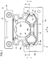
FIG. 1 is a front view of a linear guide according to a first embodiment of the present invention. -
FIG. 2 is an external view of the linear guide shown inFIG. 1 . -
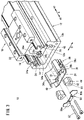
FIG. 3 is an exploded view of a part of the linear guide shown inFIG. 1 . -
FIG. 4 is a cross-sectional view taken along a line IV-IV of the linear guide ofFIG. 1 . -
FIG. 5 is a cross-sectional view taken along a line V-V of the linear guide ofFIG. 1 . -
FIG. 6 is a partial cross-sectional view of the linear guide ofFIG. 1 including a retainer. -
FIG. 7 is a partially developed view of a linear guide according to a second embodiment of the present invention. -
FIG. 8 is a partial cross-sectional view of the linear guide ofFIG. 7 including a retainer. - In the following description, when the terms in relation to the up, down, left, and right directions are used, for the sake of convenience, such terms refer to the directions shown in
FIG. 1 . However, the actual arrangement of the respective component members is not necessarily limited to this feature. - A
linear guide 10 according to a first embodiment of the present invention will be described with reference toFIGS. 1 to 6 . Thelinear guide 10 includes abody 12 to which a drive source (not shown) such as an air cylinder or an electric motor is attached, and aslider 18 that is linearly reciprocated by the drive source. - As shown in
FIGS. 1 to 3 , theslider 18 includes a rectangular parallelepiped slidermain body 20, atable portion 22 formed integrally with the slidermain body 20, and a pair ofreturn covers 26. Thereturn cover 26 is attached to both ends of the slidermain body 20 in the longitudinal direction (direction A). A workpiece can be placed on thetable portion 22.Slider guide rails 24 extending in the longitudinal direction of the slidermain body 20 are attached to both side surfaces of the slidermain body 20. The slidermain body 20 has ahole portion 20a penetrating in the longitudinal direction. A drive member (not shown) such as a ball screw for driving theslider 18 is coupled to thehole portion 20a. - Each
slider guide rail 24 includes a pair oftransfer surfaces 24a arranged in the up-down direction. Aball 48 can roll on thetransfer surfaces 24a. The slidermain body 20 internally has aball circulation path 20b having a linear track at a position corresponding to thetransfer surface 24a. That is, the slidermain body 20 has a total of four linearball circulation paths 20b in the vertical and horizontal directions. - The
body 12 is a member having a U-shaped cross section that opens upward, and has abottom wall portion 12a and a pair ofside wall portions 12b. Abody guide rail 14 extending in the longitudinal direction (direction A) of thebody 12 is attached to the inner side surface of eachside wall portion 12b. Thebody guide rail 14 is provided with aconvex portion 14a projecting toward theslider guide rail 24 over the entire length.Transfer surfaces 14b on which theballs 48 can roll are formed above and below theconvex portion 14a. Thetransfer surface 14b faces thetransfer surface 24a of theslider guide rail 24. Aside cover 16 covering a side surface of the slidermain body 20 is attached to eachside wall portion 12b of thebody 12. - The
return cover 26 includes a flat plate-shapedlower plate portion 28, anupper plate portion 30 having acurved surface 30a curved downward, and a pair of connectingwall portions 32 connecting theupper plate portion 30 to thelower plate portion 28. Thecurved surface 30a of theupper plate portion 30 has a shape matching thehole portion 20a of the slidermain body 20. Note that the pair of return covers 26 have the same structure. - As shown in
FIGS. 4 and5 , the connectingwall portion 32 includes afirst wall portion 34, asecond wall portion 36, and athird wall portion 38. Thefirst wall portion 34 extends parallel to the longitudinal direction of the slidermain body 20. Thesecond wall portion 36 extends in the width direction (direction B) of thereturn cover 26 from an end portion of thefirst wall portion 34. Thethird wall portion 38 is folded back from an end portion of thesecond wall portion 36 and extends parallel to thefirst wall portion 34. As shown inFIG. 3 , thelower plate portion 28 has astep surface 28c passing through astep portion 28b in a region surrounded by thefirst wall portion 34, thesecond wall portion 36, and thethird wall portion 38. - The
second wall portion 36 of the connectingwall portion 32 includes aball circulation path 36a. One end of theball circulation path 36a is connected to theball circulation path 20b of the slidermain body 20. The other end of theball circulation path 36a faces an end portion of theslider guide rail 24. Theball circulation path 36a has a semi-circular track. That is, thesecond wall portion 36 includes a total of four semi-circularball circulation paths 36a in the vertical and horizontal directions. - The
lower plate portion 28 hasbent portions 28a bent obliquely upward at both end portions in the widthwise direction (direction B). Theupper plate portion 30 hasbent portions 30b bent in a mountain shape at both end portions in the widthwise direction. An end portion of eachbent portion 30b of theupper plate portion 30 faces an end portion of eachbent portion 28a of thelower plate portion 28 with a predetermined clearance therebetween. Thus, openingportions 40 are formed in both side surfaces of thereturn cover 26. - The return cover 26 is attached to the slider
main body 20 by a pair ofattachment bolts 52. Specifically, apressing plate 50 is disposed outside thereturn cover 26. The pair ofattachment bolts 52 are inserted throughbolt insertion holes 50a of thepressing plate 50 andbolt insertion holes 34a of thefirst wall portion 34 of thereturn cover 26, and are screwed intobolt mounting holes 20c of the slider main body 20 (seeFIG. 3 ). - The plurality of
balls 48 are arranged in two rows in the up-down direction between eachbody guide rail 14 and eachslider guide rail 24. As theslider 18 moves, the plurality ofballs 48 roll on thetransfer surface 14b of thebody guide rail 14 and thetransfer surface 24a of theslider guide rail 24. The plurality ofballs 48 move in theball circulation path 20b of the slidermain body 20 and in theball circulation path 36a of the pair of return covers 26. - As shown in
FIGS. 3 and6 , a polygonalcolumnar lubricant retainer 42 is disposed between eachbent portion 28a of thelower plate portion 28 of thereturn cover 26 and eachbent portion 30b of theupper plate portion 30. Thelubricant retainer 42 is made up from a porous elastic body impregnated with lubricant such as grease. - An
inner side surface 42a of thelubricant retainer 42 abuts against a side surface of thefirst wall portion 34. One axial end surface (A1-direction end surface) of thelubricant retainer 42 abuts against anear 50b formed at an end portion of thepressing plate 50. The other axial end surface (A2-direction end surface) of thelubricant retainer 42 abuts against thestep portion 28b of thelower plate portion 28 and an end portion of thethird wall portion 38. That is, thelubricant retainer 42 is positioned and supported by thelower plate portion 28, theupper plate portion 30, the connectingwall portion 32, and thepressing plate 50. - The
lubricant retainer 42 includes a lubricant storage hole (lubricant storage space) 44 having a circular cross section. Thelubricant storage hole 44 passes through thelubricant retainer 42 in the axial direction. Thelubricant retainer 42 is provided with aslit 46 formed so as to be connected to thelubricant storage hole 44 by its generating line. Theslit 46 extends horizontally in a planar shape. Thelubricant storage hole 44 is filled with lubricant (lubricating oil) such as grease. Theslit 46 opens at anouter side surface 42b and at both end surfaces in the axial direction of thelubricant retainer 42. - The
outer side surface 42b of thelubricant retainer 42 protrudes from the openingportion 40 portion of thereturn cover 26 toward thebody guide rail 14. Theconvex portion 14a of thebody guide rail 14 elastically deforms thelubricant retainer 42 so as to push open theslit 46 of thelubricant retainer 42, and is inserted into theslit 46 from theouter side surface 42b of thelubricant retainer 42. One axial end side (A1-direction end portion) of thelubricant storage hole 44 is closed by thepressing plate 50. - The
lubricant retainer 42 is in sliding contact with thebody guide rail 14 at theouter side surface 42b including theslit 46. With the movement of theslider 18, thelubricant retainer 42 is brought into contact with thetransfer surface 14b of thebody guide rail 14 at various positions in the longitudinal direction, and the lubricant impregnated in thelubricant retainer 42 is uniformly supplied to thetransfer surface 14b of thebody guide rail 14. Since thelubricant storage hole 44 is filled with a predetermined amount of lubricant, a state in which thelubricant retainer 42 is impregnated with a constant amount of lubricant is maintained over a long period of time. - When an excessive amount of lubricant is supplied to the
body guide rail 14, the lubricant is sucked by thelubricant retainer 42 as theslider 18 moves. Therefore, the lubricant does not leak to the outside of thelinear guide 10. Further, when foreign matter such as dust adheres to thebody guide rail 14, thelubricant retainer 42 guides the foreign matter to the outside of thelinear guide 10 with the movement of theslider 18. Thus, the foreign matter can be removed. - According to the
linear guide 10 of the present embodiment, thelubricant retainer 42 includes therein thelubricant storage hole 44 that is filled with the lubricant. Therefore, a state in which thelubricant retainer 42 is sufficiently impregnated with the lubricant is maintained over a long period of time, and the lubricant can be continuously supplied to theguide rail 14 of thebody 12. - In the present embodiment, the
convex portion 14a of thebody guide rail 14 is inserted into theslit 46 of thelubricant retainer 42 while elastically deforming thelubricant retainer 42. Alternatively, a recess may be formed in thelubricant retainer 42 to receive theconvex portion 14a of thebody guide rail 14 in the natural state of thelubricant retainer 42. In the former case, there is an advantage that manufacturing of thelubricant retainer 42 is simple, and in the latter case, there is an advantage that sliding resistance of theslider 18 is small. - Next, a
linear guide 60 according to a second embodiment of the present invention will be described with reference toFIGS. 7 and8 . In thelinear guide 60 according to the second embodiment, the structure of alubricant retainer 62 is different from that of thelubricant retainer 42 of the first embodiment. The same structures as those of thelinear guide 10 of the first embodiment are denoted by the same reference numerals, and detailed description thereof will be omitted. - The
lubricant retainer 62 is made of a porous elastic body impregnated with lubricant such as grease, and is a member formed in a thin-film cylindrical shape having a uniform thickness. One side surface of thelubricant retainer 62 is provided with a slit-like notch 64 extending in the horizontal direction. The other side surface of thelubricant retainer 62 includes tworidge portions 66 extending in the horizontal direction and atrough portion 68 formed therebetween. Thelubricant retainer 62 includes alubricant storage space 70 inside, and thelubricant storage space 70 is filled with lubricant (lubricating oil) such as grease. - The
lubricant retainer 62 is disposed between thebent portion 28a of thelower plate portion 28 of thereturn cover 26 and thebent portion 30b of theupper plate portion 30. One side surface of thelubricant retainer 62 abuts against a side surface of thefirst wall portion 34 of thereturn cover 26. One of the opening end portions (A1-direction end portion) of thelubricant retainer 62 abuts on theear 50b of thepressing plate 50. The other opening end portion (A2-direction end portion) of thelubricant retainer 62 abuts against thestep portion 28b of thelower plate portion 28 of thereturn cover 26 and an end portion of thethird wall portion 38. That is, thelubricant retainer 62 is positioned and supported by thelower plate portion 28, theupper plate portion 30, the connectingwall portion 32, and thepressing plate 50. - The two
ridge portions 66 of thelubricant retainer 62 protrude from the openingportion 40 of thereturn cover 26 toward thebody guide rail 14. Theconvex portion 14a of thebody guide rail 14 is inserted into thetrough portion 68 of thelubricant retainer 62. An end portion of thelubricant storage space 70 in the A1 direction is closed by thepressing plate 50. - The
lubricant retainer 62 is brought into sliding contact with thetransfer surface 14b of thebody guide rail 14 at tworidge portions 66. As theslider 18 moves, thelubricant retainer 62 comes into contact with thetransfer surface 14b of thebody guide rail 14 at various positions in the longitudinal direction, and the lubricant impregnated in thelubricant retainer 62 is uniformly supplied to thetransfer surface 14b of thebody guide rail 14. Since thelubricant storage space 70 is filled with a predetermined amount of lubricant, a state in which thelubricant retainer 62 is impregnated with a constant amount of lubricant is maintained over a long period of time. - According to the
linear guide 60 of the present embodiment, thelubricant retainer 62 includes therein thelubricant storage space 70 filled with lubricant. Therefore, a state in which thelubricant retainer 62 is sufficiently impregnated with lubricant is maintained over a long period of time, and lubricant can be continuously supplied to theguide rail 14 of thebody 12. Further, since thelubricant retainer 62 is formed in a thin-film cylindrical shape, the volume of thelubricant storage space 70 provided inside thelubricant retainer 62 can be increased as much as possible, and the filling amount of lubricant can be increased as much as possible.
Claims (7)
- A linear guide (10) comprising a plurality of balls (48) arranged between a guide rail (14) of a body (12) and a guide rail (24) of a slider (18); a return cover (26) including a ball circulation path (36a), the return cover attached to the slider; a lubricant retainer (42, 62) being made up from a porous elastic body, being in a sliding contact with the guide rail of the body, being supported by the return cover, and being equipped with a lubricant storage space (44, 70) filled with lubricant.
- The linear guide according to claim 1, wherein
the lubricant retainer has a polygonal columnar shape, and the lubricant storage space is configured as a lubricant storage hole penetrating the lubricant retainer in an axial direction thereof and having a circular cross section. - The linear guide according to claim 2, wherein
an outer side surface (42b) of the lubricant retainer protrudes from an opening portion (40) provided in the return cover toward the guide rail of the body. - The linear guide according to claim 3, wherein
the lubricant retainer is provided with a slit (46) formed so as to be connected to the lubricant storage hole by a generating line of the lubricant storage hole, and a convex portion (14a) provided on the guide rail of the body is inserted into the slit. - The linear guide according to claim 1, wherein
the lubricant retainer is a member formed in a thin-film cylindrical shape. - The linear guide according to claim 5, wherein
a side face of the lubricant retainer is provided with two ridge portions (66) and a trough portion (68) formed between the two ridge portions, and the two ridge portions project toward the guide rail of the body from an opening portion provided in the return cover. - The linear guide according to claim 6, wherein
a convex portion provided on the guide rail of the body is inserted into the trough portion.
Applications Claiming Priority (1)
| Application Number | Priority Date | Filing Date | Title |
|---|---|---|---|
| JP2021063426A JP7416006B2 (en) | 2021-04-02 | 2021-04-02 | Linear guide |
Publications (2)
| Publication Number | Publication Date |
|---|---|
| EP4067681A1 true EP4067681A1 (en) | 2022-10-05 |
| EP4067681B1 EP4067681B1 (en) | 2024-01-03 |
Family
ID=80999740
Family Applications (1)
| Application Number | Title | Priority Date | Filing Date |
|---|---|---|---|
| EP22165330.6A Active EP4067681B1 (en) | 2021-04-02 | 2022-03-30 | Linear guide |
Country Status (6)
| Country | Link |
|---|---|
| US (1) | US11841050B2 (en) |
| EP (1) | EP4067681B1 (en) |
| JP (1) | JP7416006B2 (en) |
| KR (1) | KR102774694B1 (en) |
| CN (1) | CN115306824B (en) |
| TW (1) | TWI814296B (en) |
Families Citing this family (1)
| Publication number | Priority date | Publication date | Assignee | Title |
|---|---|---|---|---|
| CN118499354B (en) * | 2024-07-18 | 2024-09-27 | 湖南美创数字科技有限公司 | Quick-assembling type linear slide rail structure |
Citations (4)
| Publication number | Priority date | Publication date | Assignee | Title |
|---|---|---|---|---|
| JP2001041305A (en) | 1999-07-30 | 2001-02-13 | Iai:Kk | Actuator |
| US6401867B1 (en) * | 1998-04-16 | 2002-06-11 | Thk Co., Ltd. | Lubricant supply system |
| DE102007023182B4 (en) * | 2007-05-18 | 2009-04-09 | Hiwin Technologies Corp. | Linear drive module with a self-lubricating unit |
| CN102434585A (en) * | 2011-11-10 | 2012-05-02 | 宁波恒力汽配轴承有限公司 | Linear bearing sliding mechanism |
Family Cites Families (24)
| Publication number | Priority date | Publication date | Assignee | Title |
|---|---|---|---|---|
| NL6807674A (en) * | 1968-05-31 | 1969-12-02 | ||
| DE4141038A1 (en) * | 1991-12-12 | 1993-06-17 | Schaeffler Waelzlager Kg | SCRAPER UNIT FOR A BEARING ELEMENT |
| DE9422394U1 (en) * | 1993-04-16 | 2001-07-05 | Rexroth Star Gmbh | A linear guide unit |
| JPH0754844A (en) * | 1993-08-06 | 1995-02-28 | Nippon Seiko Kk | Lubricated linear guide device with polymer containing lubricant |
| US5429439A (en) * | 1994-06-03 | 1995-07-04 | Hiwin Technologies Corp. | Linear ball guide assembly |
| JP4268298B2 (en) * | 1999-12-28 | 2009-05-27 | 日本トムソン株式会社 | Linear motion guidance unit |
| DE60108063T2 (en) * | 2001-02-23 | 2005-12-15 | Nippon Thompson Co. Ltd. | Linear guide unit |
| JP2005337451A (en) | 2004-05-28 | 2005-12-08 | Nsk Ltd | Linear motion guide bearing device |
| JP4340617B2 (en) * | 2004-10-07 | 2009-10-07 | 日本トムソン株式会社 | Linear motion guidance unit |
| US20060102427A1 (en) * | 2004-11-12 | 2006-05-18 | Ching-Shan Wu | Lubricant supply unit |
| CN101042160B (en) * | 2006-03-20 | 2010-10-06 | 直得科技股份有限公司 | Linear slide |
| US7614790B2 (en) * | 2007-05-15 | 2009-11-10 | Hiwin Technologies Corp. | Linear driving device with a self-lubricating assembly |
| JP5164699B2 (en) * | 2008-07-04 | 2013-03-21 | 日本トムソン株式会社 | Lubricating member for linear motion rolling guide unit and slider for linear motion rolling guide unit |
| CN202646384U (en) * | 2012-05-21 | 2013-01-02 | 吴芳瑄 | Linear slides with lubrication system |
| WO2014133143A1 (en) * | 2013-03-01 | 2014-09-04 | 日本精工株式会社 | Linear motion guide device |
| US10107336B2 (en) * | 2015-03-31 | 2018-10-23 | Nsk Ltd. | Oil supply device and linear motion guide device |
| TWM519694U (en) * | 2015-10-02 | 2016-04-01 | 精浚科技股份有限公司 | Linear slide and its end cover module |
| DE102016202502A1 (en) * | 2015-11-02 | 2017-05-04 | Schaeffler Technologies AG & Co. KG | Attachment element for long-term lubrication of linear, single-row, roller-bearing circulating shoes |
| CN105673686A (en) * | 2016-03-17 | 2016-06-15 | 浙江非攻机械有限公司 | Linear movement guiding device |
| EP3225862B1 (en) * | 2016-03-29 | 2018-08-22 | Hiwin Technologies Corp. | Linear slide having lubricating device |
| CN206092702U (en) * | 2016-08-31 | 2017-04-12 | 青岛祥银传动设备有限公司 | Oil storing structure of linear guide self -lubricate system |
| KR20200107111A (en) * | 2019-03-06 | 2020-09-16 | 주식회사 엠아이디 | Case for Ball Handling of Guide Block |
| CN110360221A (en) * | 2019-06-26 | 2019-10-22 | 丽水市杰祥科技有限公司 | A kind of roller line slideway |
| KR102114799B1 (en) * | 2020-01-10 | 2020-05-25 | 주식회사아이로보 | Linear motion guide unit |
-
2021
- 2021-04-02 JP JP2021063426A patent/JP7416006B2/en active Active
-
2022
- 2022-03-23 KR KR1020220035849A patent/KR102774694B1/en active Active
- 2022-03-23 TW TW111110760A patent/TWI814296B/en active
- 2022-03-23 US US17/656,046 patent/US11841050B2/en active Active
- 2022-03-30 EP EP22165330.6A patent/EP4067681B1/en active Active
- 2022-04-01 CN CN202210347010.7A patent/CN115306824B/en active Active
Patent Citations (4)
| Publication number | Priority date | Publication date | Assignee | Title |
|---|---|---|---|---|
| US6401867B1 (en) * | 1998-04-16 | 2002-06-11 | Thk Co., Ltd. | Lubricant supply system |
| JP2001041305A (en) | 1999-07-30 | 2001-02-13 | Iai:Kk | Actuator |
| DE102007023182B4 (en) * | 2007-05-18 | 2009-04-09 | Hiwin Technologies Corp. | Linear drive module with a self-lubricating unit |
| CN102434585A (en) * | 2011-11-10 | 2012-05-02 | 宁波恒力汽配轴承有限公司 | Linear bearing sliding mechanism |
Also Published As
| Publication number | Publication date |
|---|---|
| TW202246679A (en) | 2022-12-01 |
| JP2022158484A (en) | 2022-10-17 |
| KR102774694B1 (en) | 2025-03-04 |
| US20220316526A1 (en) | 2022-10-06 |
| EP4067681B1 (en) | 2024-01-03 |
| JP7416006B2 (en) | 2024-01-17 |
| CN115306824B (en) | 2024-07-12 |
| TWI814296B (en) | 2023-09-01 |
| KR20220137541A (en) | 2022-10-12 |
| CN115306824A (en) | 2022-11-08 |
| US11841050B2 (en) | 2023-12-12 |
Similar Documents
| Publication | Publication Date | Title |
|---|---|---|
| JP4035241B2 (en) | Linear motion guide unit with lubrication device | |
| US9051966B2 (en) | Linear guide apparatus | |
| US8070360B2 (en) | Motion guide device and method of lubricating the same | |
| JP4521305B2 (en) | Linear motion guidance unit | |
| JP4685723B2 (en) | Linear motion guidance unit | |
| JP4584888B2 (en) | Linear motion guidance unit | |
| KR102796004B1 (en) | Motion guidance devices and lubrication path components used in motion guidance devices | |
| JPWO2013002064A1 (en) | Linear actuator | |
| EP4067681B1 (en) | Linear guide | |
| JP2008232305A (en) | Lubricating member for linear motion rolling guide unit and slider for linear motion rolling guide unit using the lubricating member | |
| JP5550918B2 (en) | Linear motion guidance unit | |
| JP4340617B2 (en) | Linear motion guidance unit | |
| JP4934496B2 (en) | Lubricant supply device and motion guide device with lubricant supply device | |
| JP4469705B2 (en) | Linear motion guidance unit | |
| JP3490385B2 (en) | Guide device lubrication device | |
| CN105705806B (en) | Rolling bearing guider | |
| US7410300B2 (en) | Adjusting structure for adjusting amount of lubricant applied to a linear guideway | |
| JP4233153B2 (en) | Lubricating oil supply device and linear motion device using the same | |
| JP2017141950A (en) | Oil supply device for rolling bearing guide device, rolling bearing guide device | |
| KR20230082040A (en) | linear guide | |
| TWI912717B (en) | Guiding lubrication structure of linear slide | |
| JP3929952B2 (en) | Lubricator for guide device | |
| JP2003206926A (en) | Single axis actuator | |
| JP2025012016A (en) | Linear guide | |
| JP2025021020A (en) | Linear guide |
Legal Events
| Date | Code | Title | Description |
|---|---|---|---|
| PUAI | Public reference made under article 153(3) epc to a published international application that has entered the european phase |
Free format text: ORIGINAL CODE: 0009012 |
|
| STAA | Information on the status of an ep patent application or granted ep patent |
Free format text: STATUS: THE APPLICATION HAS BEEN PUBLISHED |
|
| AK | Designated contracting states |
Kind code of ref document: A1 Designated state(s): AL AT BE BG CH CY CZ DE DK EE ES FI FR GB GR HR HU IE IS IT LI LT LU LV MC MK MT NL NO PL PT RO RS SE SI SK SM TR |
|
| STAA | Information on the status of an ep patent application or granted ep patent |
Free format text: STATUS: REQUEST FOR EXAMINATION WAS MADE |
|
| 17P | Request for examination filed |
Effective date: 20230321 |
|
| RBV | Designated contracting states (corrected) |
Designated state(s): AL AT BE BG CH CY CZ DE DK EE ES FI FR GB GR HR HU IE IS IT LI LT LU LV MC MK MT NL NO PL PT RO RS SE SI SK SM TR |
|
| GRAP | Despatch of communication of intention to grant a patent |
Free format text: ORIGINAL CODE: EPIDOSNIGR1 |
|
| STAA | Information on the status of an ep patent application or granted ep patent |
Free format text: STATUS: GRANT OF PATENT IS INTENDED |
|
| INTG | Intention to grant announced |
Effective date: 20230824 |
|
| GRAS | Grant fee paid |
Free format text: ORIGINAL CODE: EPIDOSNIGR3 |
|
| GRAA | (expected) grant |
Free format text: ORIGINAL CODE: 0009210 |
|
| STAA | Information on the status of an ep patent application or granted ep patent |
Free format text: STATUS: THE PATENT HAS BEEN GRANTED |
|
| AK | Designated contracting states |
Kind code of ref document: B1 Designated state(s): AL AT BE BG CH CY CZ DE DK EE ES FI FR GB GR HR HU IE IS IT LI LT LU LV MC MK MT NL NO PL PT RO RS SE SI SK SM TR |
|
| REG | Reference to a national code |
Ref country code: GB Ref legal event code: FG4D |
|
| REG | Reference to a national code |
Ref country code: CH Ref legal event code: EP |
|
| REG | Reference to a national code |
Ref country code: DE Ref legal event code: R096 Ref document number: 602022001516 Country of ref document: DE |
|
| REG | Reference to a national code |
Ref country code: IE Ref legal event code: FG4D |
|
| REG | Reference to a national code |
Ref country code: LT Ref legal event code: MG9D |
|
| PG25 | Lapsed in a contracting state [announced via postgrant information from national office to epo] |
Ref country code: ES Free format text: LAPSE BECAUSE OF FAILURE TO SUBMIT A TRANSLATION OF THE DESCRIPTION OR TO PAY THE FEE WITHIN THE PRESCRIBED TIME-LIMIT Effective date: 20240103 |
|
| PG25 | Lapsed in a contracting state [announced via postgrant information from national office to epo] |
Ref country code: ES Free format text: LAPSE BECAUSE OF FAILURE TO SUBMIT A TRANSLATION OF THE DESCRIPTION OR TO PAY THE FEE WITHIN THE PRESCRIBED TIME-LIMIT Effective date: 20240103 |
|
| REG | Reference to a national code |
Ref country code: NL Ref legal event code: MP Effective date: 20240103 |
|
| REG | Reference to a national code |
Ref country code: AT Ref legal event code: MK05 Ref document number: 1647076 Country of ref document: AT Kind code of ref document: T Effective date: 20240103 |
|
| PG25 | Lapsed in a contracting state [announced via postgrant information from national office to epo] |
Ref country code: NL Free format text: LAPSE BECAUSE OF FAILURE TO SUBMIT A TRANSLATION OF THE DESCRIPTION OR TO PAY THE FEE WITHIN THE PRESCRIBED TIME-LIMIT Effective date: 20240103 |
|
| PG25 | Lapsed in a contracting state [announced via postgrant information from national office to epo] |
Ref country code: NL Free format text: LAPSE BECAUSE OF FAILURE TO SUBMIT A TRANSLATION OF THE DESCRIPTION OR TO PAY THE FEE WITHIN THE PRESCRIBED TIME-LIMIT Effective date: 20240103 |
|
| PG25 | Lapsed in a contracting state [announced via postgrant information from national office to epo] |
Ref country code: IS Free format text: LAPSE BECAUSE OF FAILURE TO SUBMIT A TRANSLATION OF THE DESCRIPTION OR TO PAY THE FEE WITHIN THE PRESCRIBED TIME-LIMIT Effective date: 20240503 |
|
| PG25 | Lapsed in a contracting state [announced via postgrant information from national office to epo] |
Ref country code: LT Free format text: LAPSE BECAUSE OF FAILURE TO SUBMIT A TRANSLATION OF THE DESCRIPTION OR TO PAY THE FEE WITHIN THE PRESCRIBED TIME-LIMIT Effective date: 20240103 |
|
| PG25 | Lapsed in a contracting state [announced via postgrant information from national office to epo] |
Ref country code: GR Free format text: LAPSE BECAUSE OF FAILURE TO SUBMIT A TRANSLATION OF THE DESCRIPTION OR TO PAY THE FEE WITHIN THE PRESCRIBED TIME-LIMIT Effective date: 20240404 |
|
| PG25 | Lapsed in a contracting state [announced via postgrant information from national office to epo] |
Ref country code: HR Free format text: LAPSE BECAUSE OF FAILURE TO SUBMIT A TRANSLATION OF THE DESCRIPTION OR TO PAY THE FEE WITHIN THE PRESCRIBED TIME-LIMIT Effective date: 20240103 Ref country code: RS Free format text: LAPSE BECAUSE OF FAILURE TO SUBMIT A TRANSLATION OF THE DESCRIPTION OR TO PAY THE FEE WITHIN THE PRESCRIBED TIME-LIMIT Effective date: 20240403 |
|
| PG25 | Lapsed in a contracting state [announced via postgrant information from national office to epo] |
Ref country code: CZ Free format text: LAPSE BECAUSE OF FAILURE TO SUBMIT A TRANSLATION OF THE DESCRIPTION OR TO PAY THE FEE WITHIN THE PRESCRIBED TIME-LIMIT Effective date: 20240103 Ref country code: AT Free format text: LAPSE BECAUSE OF FAILURE TO SUBMIT A TRANSLATION OF THE DESCRIPTION OR TO PAY THE FEE WITHIN THE PRESCRIBED TIME-LIMIT Effective date: 20240103 |
|
| PG25 | Lapsed in a contracting state [announced via postgrant information from national office to epo] |
Ref country code: RS Free format text: LAPSE BECAUSE OF FAILURE TO SUBMIT A TRANSLATION OF THE DESCRIPTION OR TO PAY THE FEE WITHIN THE PRESCRIBED TIME-LIMIT Effective date: 20240403 Ref country code: NO Free format text: LAPSE BECAUSE OF FAILURE TO SUBMIT A TRANSLATION OF THE DESCRIPTION OR TO PAY THE FEE WITHIN THE PRESCRIBED TIME-LIMIT Effective date: 20240403 Ref country code: LT Free format text: LAPSE BECAUSE OF FAILURE TO SUBMIT A TRANSLATION OF THE DESCRIPTION OR TO PAY THE FEE WITHIN THE PRESCRIBED TIME-LIMIT Effective date: 20240103 Ref country code: IS Free format text: LAPSE BECAUSE OF FAILURE TO SUBMIT A TRANSLATION OF THE DESCRIPTION OR TO PAY THE FEE WITHIN THE PRESCRIBED TIME-LIMIT Effective date: 20240503 Ref country code: HR Free format text: LAPSE BECAUSE OF FAILURE TO SUBMIT A TRANSLATION OF THE DESCRIPTION OR TO PAY THE FEE WITHIN THE PRESCRIBED TIME-LIMIT Effective date: 20240103 Ref country code: GR Free format text: LAPSE BECAUSE OF FAILURE TO SUBMIT A TRANSLATION OF THE DESCRIPTION OR TO PAY THE FEE WITHIN THE PRESCRIBED TIME-LIMIT Effective date: 20240404 Ref country code: CZ Free format text: LAPSE BECAUSE OF FAILURE TO SUBMIT A TRANSLATION OF THE DESCRIPTION OR TO PAY THE FEE WITHIN THE PRESCRIBED TIME-LIMIT Effective date: 20240103 Ref country code: BG Free format text: LAPSE BECAUSE OF FAILURE TO SUBMIT A TRANSLATION OF THE DESCRIPTION OR TO PAY THE FEE WITHIN THE PRESCRIBED TIME-LIMIT Effective date: 20240103 Ref country code: AT Free format text: LAPSE BECAUSE OF FAILURE TO SUBMIT A TRANSLATION OF THE DESCRIPTION OR TO PAY THE FEE WITHIN THE PRESCRIBED TIME-LIMIT Effective date: 20240103 |
|
| PG25 | Lapsed in a contracting state [announced via postgrant information from national office to epo] |
Ref country code: PL Free format text: LAPSE BECAUSE OF FAILURE TO SUBMIT A TRANSLATION OF THE DESCRIPTION OR TO PAY THE FEE WITHIN THE PRESCRIBED TIME-LIMIT Effective date: 20240103 Ref country code: PT Free format text: LAPSE BECAUSE OF FAILURE TO SUBMIT A TRANSLATION OF THE DESCRIPTION OR TO PAY THE FEE WITHIN THE PRESCRIBED TIME-LIMIT Effective date: 20240503 |
|
| PG25 | Lapsed in a contracting state [announced via postgrant information from national office to epo] |
Ref country code: SE Free format text: LAPSE BECAUSE OF FAILURE TO SUBMIT A TRANSLATION OF THE DESCRIPTION OR TO PAY THE FEE WITHIN THE PRESCRIBED TIME-LIMIT Effective date: 20240103 Ref country code: PT Free format text: LAPSE BECAUSE OF FAILURE TO SUBMIT A TRANSLATION OF THE DESCRIPTION OR TO PAY THE FEE WITHIN THE PRESCRIBED TIME-LIMIT Effective date: 20240503 Ref country code: PL Free format text: LAPSE BECAUSE OF FAILURE TO SUBMIT A TRANSLATION OF THE DESCRIPTION OR TO PAY THE FEE WITHIN THE PRESCRIBED TIME-LIMIT Effective date: 20240103 Ref country code: LV Free format text: LAPSE BECAUSE OF FAILURE TO SUBMIT A TRANSLATION OF THE DESCRIPTION OR TO PAY THE FEE WITHIN THE PRESCRIBED TIME-LIMIT Effective date: 20240103 |
|
| REG | Reference to a national code |
Ref country code: DE Ref legal event code: R097 Ref document number: 602022001516 Country of ref document: DE |
|
| PG25 | Lapsed in a contracting state [announced via postgrant information from national office to epo] |
Ref country code: DK Free format text: LAPSE BECAUSE OF FAILURE TO SUBMIT A TRANSLATION OF THE DESCRIPTION OR TO PAY THE FEE WITHIN THE PRESCRIBED TIME-LIMIT Effective date: 20240103 |
|
| PG25 | Lapsed in a contracting state [announced via postgrant information from national office to epo] |
Ref country code: SM Free format text: LAPSE BECAUSE OF FAILURE TO SUBMIT A TRANSLATION OF THE DESCRIPTION OR TO PAY THE FEE WITHIN THE PRESCRIBED TIME-LIMIT Effective date: 20240103 |
|
| PG25 | Lapsed in a contracting state [announced via postgrant information from national office to epo] |
Ref country code: EE Free format text: LAPSE BECAUSE OF FAILURE TO SUBMIT A TRANSLATION OF THE DESCRIPTION OR TO PAY THE FEE WITHIN THE PRESCRIBED TIME-LIMIT Effective date: 20240103 |
|
| PG25 | Lapsed in a contracting state [announced via postgrant information from national office to epo] |
Ref country code: SK Free format text: LAPSE BECAUSE OF FAILURE TO SUBMIT A TRANSLATION OF THE DESCRIPTION OR TO PAY THE FEE WITHIN THE PRESCRIBED TIME-LIMIT Effective date: 20240103 |
|
| PG25 | Lapsed in a contracting state [announced via postgrant information from national office to epo] |
Ref country code: SM Free format text: LAPSE BECAUSE OF FAILURE TO SUBMIT A TRANSLATION OF THE DESCRIPTION OR TO PAY THE FEE WITHIN THE PRESCRIBED TIME-LIMIT Effective date: 20240103 Ref country code: SK Free format text: LAPSE BECAUSE OF FAILURE TO SUBMIT A TRANSLATION OF THE DESCRIPTION OR TO PAY THE FEE WITHIN THE PRESCRIBED TIME-LIMIT Effective date: 20240103 Ref country code: RO Free format text: LAPSE BECAUSE OF FAILURE TO SUBMIT A TRANSLATION OF THE DESCRIPTION OR TO PAY THE FEE WITHIN THE PRESCRIBED TIME-LIMIT Effective date: 20240103 Ref country code: EE Free format text: LAPSE BECAUSE OF FAILURE TO SUBMIT A TRANSLATION OF THE DESCRIPTION OR TO PAY THE FEE WITHIN THE PRESCRIBED TIME-LIMIT Effective date: 20240103 Ref country code: DK Free format text: LAPSE BECAUSE OF FAILURE TO SUBMIT A TRANSLATION OF THE DESCRIPTION OR TO PAY THE FEE WITHIN THE PRESCRIBED TIME-LIMIT Effective date: 20240103 |
|
| PLBE | No opposition filed within time limit |
Free format text: ORIGINAL CODE: 0009261 |
|
| STAA | Information on the status of an ep patent application or granted ep patent |
Free format text: STATUS: NO OPPOSITION FILED WITHIN TIME LIMIT |
|
| PG25 | Lapsed in a contracting state [announced via postgrant information from national office to epo] |
Ref country code: LU Free format text: LAPSE BECAUSE OF NON-PAYMENT OF DUE FEES Effective date: 20240330 |
|
| PG25 | Lapsed in a contracting state [announced via postgrant information from national office to epo] |
Ref country code: MC Free format text: LAPSE BECAUSE OF FAILURE TO SUBMIT A TRANSLATION OF THE DESCRIPTION OR TO PAY THE FEE WITHIN THE PRESCRIBED TIME-LIMIT Effective date: 20240103 |
|
| PG25 | Lapsed in a contracting state [announced via postgrant information from national office to epo] |
Ref country code: MC Free format text: LAPSE BECAUSE OF FAILURE TO SUBMIT A TRANSLATION OF THE DESCRIPTION OR TO PAY THE FEE WITHIN THE PRESCRIBED TIME-LIMIT Effective date: 20240103 Ref country code: LU Free format text: LAPSE BECAUSE OF NON-PAYMENT OF DUE FEES Effective date: 20240330 |
|
| PG25 | Lapsed in a contracting state [announced via postgrant information from national office to epo] |
Ref country code: IT Free format text: LAPSE BECAUSE OF FAILURE TO SUBMIT A TRANSLATION OF THE DESCRIPTION OR TO PAY THE FEE WITHIN THE PRESCRIBED TIME-LIMIT Effective date: 20240103 |
|
| 26N | No opposition filed |
Effective date: 20241007 |
|
| REG | Reference to a national code |
Ref country code: BE Ref legal event code: MM Effective date: 20240331 |
|
| PG25 | Lapsed in a contracting state [announced via postgrant information from national office to epo] |
Ref country code: IT Free format text: LAPSE BECAUSE OF FAILURE TO SUBMIT A TRANSLATION OF THE DESCRIPTION OR TO PAY THE FEE WITHIN THE PRESCRIBED TIME-LIMIT Effective date: 20240103 |
|
| PG25 | Lapsed in a contracting state [announced via postgrant information from national office to epo] |
Ref country code: BE Free format text: LAPSE BECAUSE OF NON-PAYMENT OF DUE FEES Effective date: 20240331 |
|
| PG25 | Lapsed in a contracting state [announced via postgrant information from national office to epo] |
Ref country code: FR Free format text: LAPSE BECAUSE OF NON-PAYMENT OF DUE FEES Effective date: 20240331 |
|
| PG25 | Lapsed in a contracting state [announced via postgrant information from national office to epo] |
Ref country code: IE Free format text: LAPSE BECAUSE OF NON-PAYMENT OF DUE FEES Effective date: 20240330 |
|
| PG25 | Lapsed in a contracting state [announced via postgrant information from national office to epo] |
Ref country code: IE Free format text: LAPSE BECAUSE OF NON-PAYMENT OF DUE FEES Effective date: 20240330 Ref country code: FR Free format text: LAPSE BECAUSE OF NON-PAYMENT OF DUE FEES Effective date: 20240331 Ref country code: BE Free format text: LAPSE BECAUSE OF NON-PAYMENT OF DUE FEES Effective date: 20240331 |
|
| PGFP | Annual fee paid to national office [announced via postgrant information from national office to epo] |
Ref country code: DE Payment date: 20250319 Year of fee payment: 4 |
|
| PG25 | Lapsed in a contracting state [announced via postgrant information from national office to epo] |
Ref country code: SI Free format text: LAPSE BECAUSE OF FAILURE TO SUBMIT A TRANSLATION OF THE DESCRIPTION OR TO PAY THE FEE WITHIN THE PRESCRIBED TIME-LIMIT Effective date: 20240103 |
|
| PG25 | Lapsed in a contracting state [announced via postgrant information from national office to epo] |
Ref country code: CY Free format text: LAPSE BECAUSE OF FAILURE TO SUBMIT A TRANSLATION OF THE DESCRIPTION OR TO PAY THE FEE WITHIN THE PRESCRIBED TIME-LIMIT; INVALID AB INITIO Effective date: 20220330 |
|
| PG25 | Lapsed in a contracting state [announced via postgrant information from national office to epo] |
Ref country code: FI Free format text: LAPSE BECAUSE OF FAILURE TO SUBMIT A TRANSLATION OF THE DESCRIPTION OR TO PAY THE FEE WITHIN THE PRESCRIBED TIME-LIMIT Effective date: 20240103 |
|
| REG | Reference to a national code |
Ref country code: CH Ref legal event code: H13 Free format text: ST27 STATUS EVENT CODE: U-0-0-H10-H13 (AS PROVIDED BY THE NATIONAL OFFICE) Effective date: 20251023 |
|
| PG25 | Lapsed in a contracting state [announced via postgrant information from national office to epo] |
Ref country code: TR Free format text: LAPSE BECAUSE OF FAILURE TO SUBMIT A TRANSLATION OF THE DESCRIPTION OR TO PAY THE FEE WITHIN THE PRESCRIBED TIME-LIMIT Effective date: 20240103 |
|
| PG25 | Lapsed in a contracting state [announced via postgrant information from national office to epo] |
Ref country code: CH Free format text: LAPSE BECAUSE OF NON-PAYMENT OF DUE FEES Effective date: 20250331 |