EP4067650A1 - Luftkühlvorrichtung, generator, luftführungsvorrichtung, windenergieanlage und verfahren zur herstellung eines generators und einer windenergieanlage - Google Patents
Luftkühlvorrichtung, generator, luftführungsvorrichtung, windenergieanlage und verfahren zur herstellung eines generators und einer windenergieanlage Download PDFInfo
- Publication number
- EP4067650A1 EP4067650A1 EP22160504.1A EP22160504A EP4067650A1 EP 4067650 A1 EP4067650 A1 EP 4067650A1 EP 22160504 A EP22160504 A EP 22160504A EP 4067650 A1 EP4067650 A1 EP 4067650A1
- Authority
- EP
- European Patent Office
- Prior art keywords
- unit
- air
- cooling
- air guiding
- wind
- Prior art date
- Legal status (The legal status is an assumption and is not a legal conclusion. Google has not performed a legal analysis and makes no representation as to the accuracy of the status listed.)
- Pending
Links
Images





Classifications
-
- F—MECHANICAL ENGINEERING; LIGHTING; HEATING; WEAPONS; BLASTING
- F03—MACHINES OR ENGINES FOR LIQUIDS; WIND, SPRING, OR WEIGHT MOTORS; PRODUCING MECHANICAL POWER OR A REACTIVE PROPULSIVE THRUST, NOT OTHERWISE PROVIDED FOR
- F03D—WIND MOTORS
- F03D80/00—Details, components or accessories not provided for in groups F03D1/00 - F03D17/00
- F03D80/60—Cooling or heating of wind motors
-
- F—MECHANICAL ENGINEERING; LIGHTING; HEATING; WEAPONS; BLASTING
- F03—MACHINES OR ENGINES FOR LIQUIDS; WIND, SPRING, OR WEIGHT MOTORS; PRODUCING MECHANICAL POWER OR A REACTIVE PROPULSIVE THRUST, NOT OTHERWISE PROVIDED FOR
- F03D—WIND MOTORS
- F03D1/00—Wind motors with rotation axis substantially parallel to the air flow entering the rotor
- F03D1/06—Rotors
- F03D1/065—Rotors characterised by their construction elements
- F03D1/0691—Rotors characterised by their construction elements of the hub
-
- F—MECHANICAL ENGINEERING; LIGHTING; HEATING; WEAPONS; BLASTING
- F03—MACHINES OR ENGINES FOR LIQUIDS; WIND, SPRING, OR WEIGHT MOTORS; PRODUCING MECHANICAL POWER OR A REACTIVE PROPULSIVE THRUST, NOT OTHERWISE PROVIDED FOR
- F03D—WIND MOTORS
- F03D80/00—Details, components or accessories not provided for in groups F03D1/00 - F03D17/00
-
- F—MECHANICAL ENGINEERING; LIGHTING; HEATING; WEAPONS; BLASTING
- F03—MACHINES OR ENGINES FOR LIQUIDS; WIND, SPRING, OR WEIGHT MOTORS; PRODUCING MECHANICAL POWER OR A REACTIVE PROPULSIVE THRUST, NOT OTHERWISE PROVIDED FOR
- F03D—WIND MOTORS
- F03D9/00—Adaptations of wind motors for special use; Combinations of wind motors with apparatus driven thereby; Wind motors specially adapted for installation in particular locations
- F03D9/20—Wind motors characterised by the driven apparatus
- F03D9/25—Wind motors characterised by the driven apparatus the apparatus being an electrical generator
-
- H—ELECTRICITY
- H02—GENERATION; CONVERSION OR DISTRIBUTION OF ELECTRIC POWER
- H02K—DYNAMO-ELECTRIC MACHINES
- H02K5/00—Casings; Enclosures; Supports
- H02K5/04—Casings or enclosures characterised by the shape, form or construction thereof
- H02K5/20—Casings or enclosures characterised by the shape, form or construction thereof with channels or ducts for flow of cooling medium
- H02K5/207—Casings or enclosures characterised by the shape, form or construction thereof with channels or ducts for flow of cooling medium with openings in the casing specially adapted for ambient air
-
- H—ELECTRICITY
- H02—GENERATION; CONVERSION OR DISTRIBUTION OF ELECTRIC POWER
- H02K—DYNAMO-ELECTRIC MACHINES
- H02K7/00—Arrangements for handling mechanical energy structurally associated with dynamo-electric machines, e.g. structural association with mechanical driving motors or auxiliary dynamo-electric machines
- H02K7/18—Structural association of electric generators with mechanical driving motors, e.g. with turbines
- H02K7/1807—Rotary generators
- H02K7/1823—Rotary generators structurally associated with turbines or similar engines
- H02K7/183—Rotary generators structurally associated with turbines or similar engines wherein the turbine is a wind turbine
- H02K7/1838—Generators mounted in a nacelle or similar structure of a horizontal axis wind turbine
-
- H—ELECTRICITY
- H02—GENERATION; CONVERSION OR DISTRIBUTION OF ELECTRIC POWER
- H02K—DYNAMO-ELECTRIC MACHINES
- H02K9/00—Arrangements for cooling or ventilating
- H02K9/02—Arrangements for cooling or ventilating by ambient air flowing through the machine
-
- H—ELECTRICITY
- H02—GENERATION; CONVERSION OR DISTRIBUTION OF ELECTRIC POWER
- H02K—DYNAMO-ELECTRIC MACHINES
- H02K9/00—Arrangements for cooling or ventilating
- H02K9/02—Arrangements for cooling or ventilating by ambient air flowing through the machine
- H02K9/04—Arrangements for cooling or ventilating by ambient air flowing through the machine having means for generating a flow of cooling medium
- H02K9/06—Arrangements for cooling or ventilating by ambient air flowing through the machine having means for generating a flow of cooling medium with fans or impellers driven by the machine shaft
-
- F—MECHANICAL ENGINEERING; LIGHTING; HEATING; WEAPONS; BLASTING
- F05—INDEXING SCHEMES RELATING TO ENGINES OR PUMPS IN VARIOUS SUBCLASSES OF CLASSES F01-F04
- F05B—INDEXING SCHEME RELATING TO WIND, SPRING, WEIGHT, INERTIA OR LIKE MOTORS, TO MACHINES OR ENGINES FOR LIQUIDS COVERED BY SUBCLASSES F03B, F03D AND F03G
- F05B2260/00—Function
- F05B2260/20—Heat transfer, e.g. cooling
- F05B2260/205—Cooling fluid recirculation, i.e. after having cooled one or more components the cooling fluid is recovered and used elsewhere for other purposes
-
- F—MECHANICAL ENGINEERING; LIGHTING; HEATING; WEAPONS; BLASTING
- F05—INDEXING SCHEMES RELATING TO ENGINES OR PUMPS IN VARIOUS SUBCLASSES OF CLASSES F01-F04
- F05B—INDEXING SCHEME RELATING TO WIND, SPRING, WEIGHT, INERTIA OR LIKE MOTORS, TO MACHINES OR ENGINES FOR LIQUIDS COVERED BY SUBCLASSES F03B, F03D AND F03G
- F05B2260/00—Function
- F05B2260/20—Heat transfer, e.g. cooling
- F05B2260/221—Improvement of heat transfer
- F05B2260/224—Improvement of heat transfer by increasing the heat transfer surface
- F05B2260/2241—Improvement of heat transfer by increasing the heat transfer surface using fins or ribs
-
- Y—GENERAL TAGGING OF NEW TECHNOLOGICAL DEVELOPMENTS; GENERAL TAGGING OF CROSS-SECTIONAL TECHNOLOGIES SPANNING OVER SEVERAL SECTIONS OF THE IPC; TECHNICAL SUBJECTS COVERED BY FORMER USPC CROSS-REFERENCE ART COLLECTIONS [XRACs] AND DIGESTS
- Y02—TECHNOLOGIES OR APPLICATIONS FOR MITIGATION OR ADAPTATION AGAINST CLIMATE CHANGE
- Y02E—REDUCTION OF GREENHOUSE GAS [GHG] EMISSIONS, RELATED TO ENERGY GENERATION, TRANSMISSION OR DISTRIBUTION
- Y02E10/00—Energy generation through renewable energy sources
- Y02E10/70—Wind energy
- Y02E10/72—Wind turbines with rotation axis in wind direction
Definitions
- the invention relates to an air-cooling device for air-cooling a generator of a wind power plant by means of wind, comprising a cooling unit of the generator with a cooling-unit outer surface against which the wind flows for air-cooling the generator when the wind power plant is in operation. Furthermore, the invention relates to a generator of a wind energy plant.
- the invention relates to an air guiding device for providing wind for air cooling on a cooling unit of a generator of a wind turbine, comprising a rotation unit of an aerodynamic rotor of the wind turbine with an outer surface of the rotation unit, along which the wind flows during operation of the wind turbine, the rotation unit having connections for attachment and/or through-openings for the passage of rotor blades of the aerodynamic rotor. Furthermore, the invention relates to a wind energy plant.
- the invention relates to a method for producing a generator of a wind energy installation with an air cooling device and a method for producing a wind energy installation.
- Wind power plants are known.
- a currently common type of wind turbine is a so-called horizontal axis wind turbine, usually with three rotor blades.
- Such wind energy installations are increasingly being constructed in larger sizes, namely in particular higher hub or axle heights and larger rotor diameters with the corresponding larger generator and larger feed-in capacity.
- Larger generators require higher cooling capacities in order to operate the generator at an optimal operating temperature.
- active cooling units generate a cooling medium flow, for example an air flow, which is guided along the surfaces of the generator to be cooled.
- a cooling medium flow for example an air flow
- coolant can be routed through pipes that transport the heat away.
- generators can be operated at an optimum operating temperature.
- wind power plants with such active cooling units are expensive to manufacture on the one hand and to operate on the other hand, in particular with regard to servicing and maintenance work.
- German Patent and Trademark Office has researched the following prior art in the priority application for the present application: DE 103 51 844 A1 , DE 10 2007 042 338 A1 , U.S. 8,047,774 B2 , EP 2 546 595 A1 , CN 104956075A .
- the invention is therefore based on the object of providing an air cooling device, a generator, an air guiding device, a wind energy installation and a method for producing a generator and a wind energy installation which addresses the problems mentioned.
- the invention is based on the object of providing an air cooling device, a generator, an air guiding device, a wind power plant and a method for producing a generator and a wind power plant, which enables operation of a generator of a wind power plant at an optimal operating temperature.
- the invention is preferably based on the object of providing an air cooling device, a generator, an air guiding device, a wind energy installation and a method for producing a generator as well as to provide a wind power plant, which enables a more cost-effective production and a more cost-effective operation of a wind power plant.
- an air cooling device for air cooling of a generator of a wind turbine by means of wind comprising an air guiding device which is arranged on the cooling unit and extends outwards in a radial direction starting from the outer surface of the cooling unit and is designed in in an operating state of the wind turbine, directing the wind for air cooling in the radial direction inwards in the direction of the cooling unit.
- the invention is based on the finding that the wind which flows on and around the wind energy plant can be guided by an air-guiding device in the direction of the cooling unit of a generator.
- the air guide has the effect of accelerating the wind, which thus flows past the cooling unit at a higher speed and achieves a better cooling effect.
- the air guiding device has the effect, in particular, that the wind is deflected in a radial direction that guides the wind into an interior of the cooling unit.
- a generator can be operated at an optimal operating temperature, but in any case closer to the optimal operating temperature.
- the cooling unit i.e. the generator, can be evenly cooled by the air guiding device. This leads to a low temperature gradient, particularly in the axial direction and circumferential direction, which in turn increases the efficiency of a generator.
- passive cooling has the advantage that the use of energy for active cooling is minimized or even completely avoided, which in turn saves costs.
- the wind energy installation extends from a foundation with a tower to a nacelle on which the aerodynamic rotor with the rotor blades is arranged.
- the wind energy installation or the tower extends in a substantially vertical direction in the operating state.
- the foundation forms a lower end of the wind turbine and the nacelle with the aerodynamic rotor forms an upper end.
- the generator which is coupled to the aerodynamic rotor, is arranged inside the nacelle.
- the nacelle can be mounted so that it can rotate about a nacelle axis when the wind energy installation is in operation.
- the nacelle axis is generally oriented essentially vertically. Due to the rotatable mounting of the nacelle around the nacelle axis, the aerodynamic rotor of the wind turbine can be aligned depending on the wind direction.
- the generator arranged in the nacelle has a stator with an axis of rotation about which a rotor of the generator is rotatably mounted relative to the stator of the generator in order to generate electrical energy from kinetic energy.
- the generator is designed as a multi-pole, in particular externally excited, synchronous generator.
- the axis of rotation is preferably aligned essentially orthogonally to the axis of the nacelle.
- the axis of rotation is oriented at a slight incline relative to the axis of the gondola.
- the cooling unit is preferably arranged on the generator.
- the cooling unit is arranged on an outer surface of the generator when the wind energy installation is in operation.
- the cooling unit is attached to the nacelle in the operating state of the wind energy installation. In any case, it is preferable for the cooling unit to be thermally coupled to the generator when the wind energy installation is in operation.
- position and location information refers to the operating state of a wind turbine, especially on the axis of rotation of the generator.
- an axial direction essentially corresponds to an alignment or orientation of the axis of rotation of the generator.
- the alignment of the axes can deviate from the alignment of the axes in the operating state of the wind turbine.
- the cooling unit extends in the axial direction with a cooling unit length between first and second ends.
- the axial direction preferably corresponds to an orientation of the axis of rotation of the generator.
- the cooling unit In the circumferential direction, orthogonal to the axial direction, the cooling unit extends in particular with a cooling unit width between a first and a second side.
- the cooling unit extends orthogonally to the axial direction and the circumferential direction between a cooling unit inner surface and the cooling unit outer surface with a cooling unit height.
- the cooling unit height is smaller than the cooling unit width. Furthermore, it is preferred that the cooling unit width is smaller than the cooling unit length.
- the cooling unit is designed as a partially ring-shaped cooling segment. It can also be preferred that the cooling unit comprises one or more partially ring-shaped cooling segments.
- the outer surface of the cooling unit is preferably planar. It can also be preferred that the outer surface of the cooling unit has a profiled design.
- the cooling unit outer surface can have elevations or extensions which extend outwards in the radial direction and/or have recesses which extend inwards in the radial direction.
- the cooling unit outer surface can have a rib-shaped and/or wavy and/or tubular profile and/or channel-shaped profile.
- the cooling unit In the operating state, the cooling unit is arranged on an outside of the generator. To cool the generator, it is thermally coupled to the cooling unit.
- the gondola preferably forms the cooling unit or accommodates it on the outside.
- the gondola has one or more openings in which the cooling unit is arranged.
- the one or more openings can be ring-shaped or partially ring-shaped.
- an outside of a stator and/or a generator can form or be the cooling unit.
- the air guiding device is designed to guide the wind for air cooling in the radial direction inwards in the direction of the cooling unit in the operating state of the wind energy installation.
- the air-guiding device is preferably arranged inclined relative to the outer surface of the cooling unit.
- the air guiding device is arranged in such a way that it forms one or more air guiding channels which guide the wind for air cooling in the radial direction inwards in the direction of the cooling unit.
- the one or more air ducts are aligned with the wind direction when the wind energy installation is in operation, so that the wind which flows around the wind energy installation enters the one or more air ducts.
- the air guiding device which extends outwards in the radial direction starting from the outer surface of the cooling unit, is arranged at a distance from the cooling unit.
- the air guiding device can be arranged at a distance from the cooling unit in the radial direction.
- the air guiding device has a distance in the radial direction which corresponds to at least 0%, 1%, 5%, 10%, 20%, 30%, 40%, 50%, 100%, 150% or 200% of the cooling unit length and/or maximum 0%, 1%, 5%, 10%, 20%, 30%, 40%, 50%, 100%, 150% or 200% of the cooling unit length.
- the cooling unit forms the air guiding device integrally.
- the air guiding device is attached to the outer surface of the cooling unit.
- the air guiding device is preferably connected to the cooling unit in a non-positive and/or material and/or positive manner.
- the air guiding device is welded to the cooling unit.
- the air guiding device has a first air guiding unit which, starting from the outer surface of the cooling unit, extends outwards at an acute angle in the radial direction and/or forms a converging first air guiding channel with the cooling unit, which is formed in the Operating state of the wind turbine to guide the wind for air cooling in the radial direction inward towards the cooling unit.
- the cooling unit has a plurality of cooling fins with a main extension in an axial direction, which are arranged spaced apart in a circumferential direction orthogonally to the axial direction, and the air guiding device has a main extension essentially in the circumferential direction.
- the first air guide unit is arranged on the cooling unit outer surface in such a way that it extends outward at an acute angle in the radial direction.
- An acute angle is between a minimum of 0° and a maximum of 90°.
- the acute-angled arrangement of the first air guiding unit has the effect that the wind, which flows essentially axially when the wind turbine is in the operating state, is diverted inwards in the radial direction in the direction of the cooling unit.
- the first air guiding unit is preferably designed in the form of a part ring or ring.
- the first air guiding unit extends in the axial direction with a first length, in the circumferential direction with a first width and in the radial direction with a first height.
- the first width is preferably greater than the first length and/or the first height.
- the first air conduction unit has a linear profile.
- a linear profile has no curvature.
- the first air guiding unit has a curved profile and/or profile with edges.
- the edge of the profile of the first air guiding unit preferably has an edge length which preferably corresponds to at least 0% and at most 200% of the length of the cooling unit, which is between the first End and second end extends.
- the profile of the first air guiding unit can also be S-shaped.
- the profile of the first air guiding unit can have convex and/or concave profile sections.
- the acute-angled arrangement of the first air guiding unit on the outer surface of the cooling unit has the advantage of directing the wind, which flows around the wind energy installation in its operating state, particularly efficiently in the direction of the cooling unit lying radially on the inside.
- wind can be provided in sufficient quantity and at a suitable speed for cooling at the cooling unit.
- the first air guiding unit is arranged on the cooling unit in such a way that it forms a first air guiding channel which converges with the outer surface of the cooling unit.
- the air duct has an inlet opening through which the wind enters when the wind turbine is in operation, and an outlet opening through which the wind exits when the wind turbine is in operation.
- the cross-section of the duct decreases in the direction of flow.
- the inlet opening can be smaller than the outlet opening.
- the first air duct converges in the axial direction.
- the first converging air duct is ring-shaped.
- the first converging air duct has a constant cross section in the circumferential direction.
- Such a converging air duct has the advantage that the wind is accelerated in the direction of the cooling unit, which further improves the cooling capacity of the air cooling device.
- the cooling unit has a plurality of cooling fins which are arranged at a distance from one another in the circumferential direction.
- the cooling ribs arranged adjacent to each other in the circumferential direction define in particular a ventilation duct which has a main extension in the axial direction.
- the air supplied through the first air guiding unit can flow in the ventilation ducts for cooling the generator or the cooling unit.
- the cooling unit designed with cooling ribs has the effect that the area over which the heat of the generator can be dissipated is increased. Furthermore, the cooling fins have the effect of directing the supplied wind axially over the cooling unit length for an improved cooling effect. In particular, the in Circumferentially spaced cooling fins ventilation ducts, which can accelerate the supplied wind again and further improve the cooling performance of the air cooling device.
- the air guiding device comprises a second and/or third air guiding unit.
- the second air guiding unit is arranged offset in the axial direction in relation to the first air guiding unit and, starting from the cooling unit outer surface, extends outwards at an acute angle in the radial direction and/or forms a converging second air guiding channel with that of the cooling unit, which is formed in the operating state of the wind turbine directing the wind for air cooling inward in the radial direction toward the cooling unit.
- the third air guiding unit is arranged offset in the axial direction with respect to the first and/or second air guiding unit and, starting from the cooling unit outer surface, extends outwards at an acute angle in the radial direction and/or forms with that of the cooling unit a converging third air guiding channel which is formed in to direct the wind for air cooling in the radial direction inward towards the cooling unit in the operating state of the wind turbine.
- the second and/or third air guiding unit are arranged on the cooling unit outer surface in such a way that they extend outwards at an acute angle in the radial direction.
- the acute-angled arrangement of the second and/or third air guiding unit has the effect that when the wind turbine is in the operating state, the wind that flows essentially axially is diverted inward in the radial direction in the direction of the cooling unit.
- the second and/or third air guiding unit are preferably designed in the form of a part ring or ring.
- the second and/or third air guiding unit extend in the axial direction with a second and/or third length, in the circumferential direction with a second and/or third width and in the radial direction with a second and/or third height.
- the second or third width is preferably greater than the second or third length and/or the second or third height.
- the second and/or third air guiding unit preferably has a linear profile. It can be preferred that the second and/or third air guiding unit has a curved profile and/or profile with edges.
- the Edge of the profile of the second and/or third air guiding unit has an edge length which preferably corresponds to at least 0% and at most 200% of the length of the cooling unit, which extends between the first end and the second end.
- the profile of the second and/or third air guiding unit can also be S-shaped.
- the profile of the second and/or third air guiding unit can have convex and/or concave profile sections.
- the acute-angled arrangement of the second and/or third air guiding unit on the outer surface of the cooling unit has the advantage of directing the wind, which flows around the wind energy installation in its operating state, particularly efficiently in the direction of the radially inner cooling unit.
- wind can be provided in sufficient quantity and at a suitable speed for cooling at the cooling unit.
- the second and/or third air guiding unit is arranged on the cooling unit in such a way that it forms a second and/or third air guiding channel with the outer surface of the cooling unit, each of which converges.
- the air duct has an inlet opening through which the wind enters when the wind turbine is in operation, and an outlet opening through which the wind exits when the wind turbine is in operation.
- the second and/or third air duct converges in the axial direction.
- the second and/or third converging air duct is ring-shaped.
- the second and/or third converging air duct has a constant cross section in the circumferential direction.
- Such converging air ducts have the advantage that the wind is accelerated in the direction of the cooling unit, which further improves the cooling capacity of the air cooling device.
- the first air conduction unit is offset relative to the second and/or third air conduction unit.
- the third air guiding unit is preferably arranged between the first and second air guiding unit.
- the first air guiding unit is at a distance of at least 0%, 10%, 20%, 30%, 40%, 50%, 100%, 200%, 300%, 400%, 500% from the second and/or third air guiding unit. or spaced 1000% of the first length of the first air duct unit.
- the first air guiding unit is at a maximum distance from the second and/or third air guiding unit 0%, 10%, 20%, 30%, 40%, 50%, 100%, 200%, 300%, 400%, 500% or 1000% of the first length of the first air guiding unit spaced apart.
- the first air guiding unit is preferably arranged at a distance from the first end. It can be preferred that the first air guiding unit is arranged at the first end. Preferably, the first air guide unit is spaced a distance of at least 0%, 10%, 20%, 30%, 40%, 50% or 60% of the cooling unit length from the first end of the cooling unit. Additionally or alternatively, the first air guiding unit is arranged at a maximum distance of 0%, 10%, 20%, 30%, 40%, 50% or 60% of the cooling unit length from the first end of the cooling unit.
- the second air guiding unit is arranged at a distance from the second end.
- An air guiding device having a plurality of air guiding units has the advantage that the air guiding units can be arranged on the cooling unit depending on the inflow profile of the wind.
- the inflow profile can depend on the type of wind turbine.
- this allows the amount of wind that can be supplied to the cooling unit to be increased.
- This increases the cooling capacity and enables the wind turbine to be operated at an optimal operating temperature.
- such an arrangement has the advantage that the cooling unit and thus the generator are cooled uniformly in the circumferential direction and in the axial direction. In particular, the arrangement allows a temperature gradient in the axial direction and/or circumferential direction on the cooling unit or the generator to be minimized.
- the first and/or second and/or third air guiding unit is formed from one or more partial ring segments.
- This preferred embodiment has the advantage that the air cooling device can be installed particularly easily and inexpensively.
- air cooling devices for generators with a particularly large diameter can also be provided and passively cooled despite the existing transport-related size restrictions.
- the first air guiding unit extends at a first acute angle
- the second air guiding unit extends at a second acute angle
- the third air guiding unit extends at a third acute angle
- the first and /or second and/or third acute angles are equal
- the first acute angle is smaller than the second and/or third acute angle
- the first acute angle is larger than the second and/or third acute angle
- the first air guiding unit extends in the radial direction with a first height
- the second air guiding unit extends in the radial direction with a second height
- the third air guiding unit extends in the radial direction with a third height
- the first and /or the second and/or third height are the same and/or the first height is less than the second and/or third height
- the first air guiding unit extends in the first air guiding unit
- the first and/or second and/or third acute angles are at least 0°, 10°, 15°, 20°, 25°, 30°, 35°, 40°, 45°, 50°, 60°, 70°, 80°, 90° or more and a maximum of 0°, 10°, 15°, 20°, 25°, 30°, 35°, 40°, 45°, 50°, 60°, 70°, 80° or 90° .
- the first acute angle is preferably smaller than the second and/or third acute angle.
- the third acute angle is smaller than the second acute angle.
- the first acute angle is 20° or 30°.
- the second and/or third acute angle is 30° or 35°.
- first acute angle is larger than the second and/or third acute angle.
- third acute angle is larger than the second acute angle.
- first and/or second and/or third acute angles are the same.
- first air-guiding unit and/or the second air-guiding unit and/or the third air-guiding unit extends at an acute angle, starting from the cooling-unit outer surface, so that wind can flow between the cooling-unit outer surface and the first air-guiding unit and/or the second air guiding unit and/or the third air guiding unit is routed.
- first air-guiding unit and/or the second air-guiding unit and/or the third air-guiding unit opens starting from the outer surface of the cooling unit at an acute angle in the direction of the oncoming wind.
- a first and/or second and/or third obtuse angle is formed between the outer surface of the cooling unit and the first air guiding unit and/or the second air guiding unit and/or the third air guiding unit, which in the operating state differs from the inflow direction away from the wind.
- the first acute angle and the first obtuse angle together form 180° and/or the second acute angle and the second obtuse angle together form 180° and/or the third acute angle and the third obtuse angle together form 180°.
- the first and/or the second and/or the third obtuse angle are greater than 90° and less than 180°.
- the first and/or second and/or third height correspond to a minimum of 0mm, 50mm, 100mm, 150mm, 200mm, 300mm or more and a maximum of 0mm, 50mm, 100mm, 150mm, 200mm or 300mm.
- the first height is preferably smaller than the second and/or third height.
- the third height is smaller than the second height.
- the first and/or second and/or third length correspond to at least 0mm, 50mm, 100mm, 150mm, 200mm, 300mm or more and a maximum of 0mm, 50mm, 100mm, 150mm, 200mm or 300mm.
- the first length is preferably smaller than the second and/or third length.
- the third length is smaller than the second length.
- the first length is 150 mm.
- the second and/or third length is 200 mm.
- the first and/or second and/or third length correspond to at least 1%, 10%, 20%, 30%, 40% or 50% of the length of the cooling unit and/or a maximum of 1%, 10%, 20 %, 30%, 40% or 50% of the cooling unit length.
- the cooling unit is located in the axial direction between a first end, which is arranged upstream in relation to the wind direction of the wind when the wind turbine is in the operating state, and a second end, which is situated in the operating state of the wind turbine is arranged upstream of the first end in the wind direction of the wind, wherein the first air guiding unit is arranged in a first third and/or a first half of the cooling unit in relation to the extent of the cooling unit starting from the first end in the axial direction, and/ or the second air guiding unit in relation to the extent of the cooling unit starting from the first end in the axial direction a second or third third and/or a second half of the cooling unit is arranged, and/or the third air guiding unit is arranged in a first, second or third third and/or a first or second half of the cooling unit in relation to the extent of the cooling unit starting from the first end in the axial direction.
- This embodiment has the advantage that a temperature gradient of the cooling unit or of the generator to be cooled can be minimized in the axial direction and circumferential direction. In a particularly preferred manner, this leads to an improved efficiency of the generator.
- the first and/or second and/or third air guiding unit each have a base element, which is designed for arranging the respective air guiding unit on the cooling unit, and/or an air guiding element, which extends from the Base element extends at an acute angle and forms a converging air duct with the cooling unit, which is designed to direct the wind for air cooling in the direction of the cooling unit in the operating state of the wind turbine, and/or a flange, which extends at an angle from the base element and for the connection of is formed in the circumferential direction adjacent arranged air guiding units.
- Such a preferred embodiment enables the air guiding device to be fitted to the cooling unit in a particularly easy and cost-effective manner.
- this preferred embodiment has the advantage that existing generators that are already in operation can be easily and inexpensively retrofitted with such an air cooling device. Furthermore, this has the effect that the generator can be installed both in the factory and at the installation site of the wind turbine.
- the air cooling device has a damping unit which is arranged between the air guiding device and the cooling unit.
- the air guiding device extends in the operating state in the axial direction between an air guiding leading edge and an air feeding edge, with the air guiding leading edge being arranged upstream relative to the air feeding edge in relation to the wind.
- wind in the direction of flow comes into contact with the air guide device for the first time in the operating state.
- the leading edge of the air guide preferably has a main extension direction in the circumferential direction on.
- the wind guided by the air guiding device in the operating state is preferably introduced into the cooling unit on the outer surface of the cooling unit.
- the air-introduction edge is preferably arranged downstream of the air-guiding inflow edge.
- the air guiding device is in contact with the oncoming wind at the air inlet edge for the last time before it is guided into the cooling unit for cooling.
- the cooling unit outer surface has a cooling unit leading edge and the air guiding device is arranged on the cooling unit in such a way that the cooling unit leading edge is arranged in the axial direction between the air guiding leading edge and the air inlet edge.
- the cooling unit leading edge is the first end of the cooling unit.
- the leading edge of the cooling unit is arranged downstream of the air-guiding leading edge and upstream of the air-introducing edge in the flow direction of the wind. This arrangement allows the cooling capacity to be increased again in a preferred manner.
- the cooling unit outer surface extends starting from the cooling unit leading edge in the axial direction with a cooling unit cooling length and the distance between the air guide leading edge and the cooling unit leading edge is at least 0% of the cooling unit cooling length and at most 100% of the cooling unit -Cooling length.
- the cooling unit extends between the first end and the second end with the cooling unit cooling length.
- the air guiding device has a fourth air guiding unit which, starting from the outer surface of the cooling unit, extends outwards at an obtuse angle in the radial direction.
- the obtuse angle is in particular an angle greater than 90° and less than 180°.
- the obtuse angle is the angle between the cooling unit outer surface and the fourth air guide unit, which opens in the flow direction of the wind.
- a fourth acute angle is formed between the fourth air guiding unit and the outer surface of the cooling unit, which angle faces away from the oncoming flow direction of the wind in the operating state.
- the fourth acute angle is preferably greater than 0° and smaller than 90°.
- the fourth acute angle and the fourth obtuse angle together form 180°.
- the object is achieved by a generator of a wind energy installation comprising an air cooling device as described above.
- an air guiding device comprising one or more air guiding units on the rotating unit outer surface of the rotating unit between the connections or the through-openings, which extends and is formed starting from the rotating unit outer surface in a radial direction outwards to direct the wind for air cooling of the generator to the cooling unit.
- the rotation unit is in particular a spinner, a hub or some other suitable element of the aerodynamic rotor of a wind turbine.
- the one or more air guiding units are in particular designed in the shape of shovels. It can be preferred that the one or more air guiding units have a profile with a curvature. In particular, the one or more air guiding units have a linear and/or convex and/or concave and/or s-shaped profile. In particular, the one or more air guiding units can have a profile with an edge and/or a crack.
- the air guiding device has one or more covers.
- the one or more covers is or are arranged on a side of the one or more air ducting units that is on the outside in the radial direction.
- the one or more covers are arranged on the rotation unit in such a way that the one or more air guiding units extend in the radial direction between the rotation unit outer surface of the rotation unit and the cover.
- the air ducts are particularly preferably suitable for directing the wind, which flows against and around the wind turbine in its operating state, in the direction of the generator to be cooled, in particular in the direction of a cooling unit designed or arranged on the generator, for improved cooling performance.
- the rotation unit extends in the axial direction with a rotation unit length.
- the one or more air guide units extend in the axial direction with an air guide unit length.
- the one or more air duct units preferably extend with an air duct unit length which is at least 10%, 20%, 30%, 40%, 50%, 60%, 70%, 80%, 90%, 100%, 110%, 120% , 130%, 140%, 150% or more of the rotation unit length and/or a maximum of 10%, 20%, 30%, 40%, 50%, 60%, 70%, 80%, 90%, 100%, 110%, 120%, 130%, 140%, 150% or less that corresponds to the rotation unit length.
- the one or more air duct units extend in the radial direction with an air duct unit height.
- the one or more air duct units preferably extend with an air duct unit height which is at least 1%, 10%, 20%, 30%, 40%, 50%, 60%, 70%, 80%, 90%, 100%, 110% , 120%, 130%, 140%, 150%, 1000% or more of the air duct unit length and/or a maximum of 1%, 10%, 20%, 30%, 40%, 50%, 60%, 70%, 80%, 90%, 100%, 110%, 120%, 130%, 140%, 150%, 1000% or less of the air duct length.
- the one or more air guiding units extend outwards at an angle in the radial direction, starting from the outer surface of the rotating unit.
- the one or more air guiding units extend outwards at an angle of inclination in the radial direction, starting from the outer surface of the rotating unit.
- the angle of inclination is preferably at least -85°, -80°, -70°, -60°, -50°, -40°, -30°, -20°, -10°, 0°, +10°, +20 °, +30°, +40°, +50°, +60°, +70°, +80°, +85° and/or maximum -85°, -80°, -70°, -60°, - 50°, -40°, -30°, -20°, -10°, 0°, +10°, +20°, +30°, +40°, +50°, +60°, +70°, +80° or +85°.
- the one or more air guiding units are arranged with an inflow angle relative to the axial direction, in particular relative to the axis of rotation.
- the angle of attack describes an angle of the one or more air duct units in relation to the axis of rotation about an axis that is orthogonal to the rotary unit outer surface.
- the angle of attack is preferably at least -85°, -80°, -70°, -60°, -50°, -40°, -30°, -20°, -10°, 0°, +10°, +20 °, +30°, +40°, +50°, +60°, +70°, +80°, +85° and/or maximum -85°, -80°, -70°, -60°, - 50°, -40°, -30°, -20°, -10°, 0°, +10°, +20°, +30°, +40°, +50°, +60°, +70°, +80°, +85°.
- the rotation unit is located in an axial direction between a first end, which is arranged upstream in the operating state of the wind energy plant in relation to the wind direction of the wind, and a second end, which in the operating state of the wind energy plant is situated in relation to the wind direction of the wind is arranged downstream of the first end, wherein the one or more air guiding units are arranged on the rotation unit such that they extend between the first and second end of the rotation unit, and/or in the axial direction over the second end extend out. Additionally and/or alternatively, it is provided that the one or more air guiding units extend outwards at an angle of inclination in the radial direction, starting from the outer surface of the rotating unit.
- the object is achieved by a wind energy installation having a generator as described above and/or an air guiding device as described above.
- a method for producing a generator of a wind turbine with an air cooling device comprising the steps: providing a cooling unit of a generator and an air guiding device, which has a first and/or second and/or third ring segment designed as a partial ring segment stationary air guide unit comprises; Arranging the air guiding device on a cooling unit outer surface, wherein preferably the cooling unit has a plurality of cooling fins with a main extension in an axial direction, which are arranged spaced apart in a circumferential direction orthogonal to the axial direction, and the air guiding device preferably has a main extension essentially in a circumferential direction, orthogonal to the having an axial direction; and attaching the airfoil to the cooling unit exterior surface.
- the step of attaching the air guiding device to the outer surface of the cooling unit comprises: a material connection, in particular a welded connection, and/or a non-positive connection, in particular a screw connection, and/or a form-fitting connection of the air guiding device to the cooling unit and/or integral connection, in particular welded connection, and/or non-positive connection, in particular screw connection, and/or form-fit connection, of adjacent partial ring segments of a first air guiding unit, so that these form a first air guiding unit designed as a ring, and/or of adjacent partial ring segments of a second air guiding unit, so that these form a second air guiding unit configured as a ring, and/or adjacent partial ring segments of a third air guiding unit, so that these form a third air guiding unit configured as a ring, and/or preferably arranging a Dampening unit between the air guide and the cooling unit.
- a method for producing a wind turbine comprising the steps: providing a rotation unit of an aerodynamic rotor of the wind turbine with a rotation unit outer surface, along which the wind flows during operation of the wind turbine, arranging one or more Air guiding units on the rotating unit outer surface of the rotating unit between the connections or the passage openings, and/or fastening the rotating unit to a generator, in particular a generator described above or a generator produced according to a method described above.
- FIG. 1 shows a schematic representation of a wind turbine 100 according to the invention.
- the wind turbine 100 has a tower 102 and a nacelle 104 on the tower 102 .
- An aerodynamic rotor 106 with three rotor blades 108 and a spinner 110 is provided on the nacelle 104 .
- the aerodynamic rotor 106 is set in rotary motion by the wind and thus also rotates an electrodynamic rotor or rotor of a generator, which is directly or indirectly coupled to the aerodynamic rotor 106 .
- the electrical generator is arranged in the nacelle 104 and generates electrical energy.
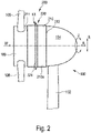
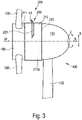
- FIGS. 2 and 3 each show a schematic side view of a wind turbine 100 with a generator with a first and second preferred embodiment of an air cooling device 200 2 and 3
- the wind turbine 100 shown is based on the 1 described wind energy installation 100.
- a cooling unit 210 of the generator is arranged on the nacelle 104, on which the wind W flows in the operating state of the wind energy installation 100 for passive cooling of the generator.
- the cooling unit 210 is ring-shaped and has a radially outer cooling unit outer surface 210a, along which the wind W flows to cool the generator.
- the gondola has an annular opening for accommodating the cooling unit.
- An air cooling device 200 is arranged on the cooling unit 210, i.e. here on the cooling unit outer surface 210a.
- the air cooling device 200 has a first air guide unit 221, which extends outward at an acute angle in the radial direction R, starting from the cooling unit outer surface 210a.
- the first air guiding unit 221 forms a first air guiding duct K1 with the cooling unit outer surface 210a.
- the cross section of the first air duct K1 decreases in the wind direction along the axial direction A.
- the first air duct K1 is a converging air duct which converges downwind, i.e. downstream.
- the first air duct K1 guides the wind W in the direction of the cooling unit 210 for air cooling of the generator.
- the cooling unit 210 extends in the axial direction A between a first end 211, which is arranged upstream in the operating state of the wind turbine 100 in relation to the wind direction of the wind W, and a second end 212, which is in the operating state of the wind turbine 100 in relation to the wind direction of Wind W is located upstream of the first end 211.
- the first air guiding unit 221 is arranged centrally between the first end 211 and the second end 212 in relation to the extension of the cooling unit 210 in the axial direction A.
- the air cooling device 200 is annular. In this preferred embodiment, the air cooling device 200 completely encloses the cooling unit 210 or the generator. Alternatively, it may be preferable for the air cooling device 200 to be designed in the form of a partial ring, as is shown in 3 is shown. In this preferred embodiment, the air cooling device 200 only partially encloses the cooling unit 210 or the generator.
- the in the 2 and 3 shown first air guiding unit 221 of the air guiding device 220 comprises several partial ring segments.
- the air cooling device 200 shown comprises, for example, six partial ring segments and the 3 Air cooling device 200 shown comprises, for example, two partial ring segments.
- FIGS 4a and 4b each show a schematic three-dimensional, detailed view of a cooling unit 210 with a first and second exemplary embodiment of an air cooling device 200, each with a single first air guiding unit 221.
- the cooling unit 210 has a plurality of cooling fins with a main extension in the axial direction A, which are arranged in the circumferential direction U orthogonal to the axial direction A spaced.
- the air guiding device 220 has a main extension in the circumferential direction U, which is essentially transverse to the wind direction of the wind W in the operating state of the wind energy installation 100.
- the first air guide unit 221 has a linear profile. in the in Figure 4b In the illustrated embodiment, the profile of the first air guiding unit 221 is S-shaped, ie it has convex and concave profile sections. In both embodiments, the first air guiding unit 221 is arranged in a first third of the cooling unit 210 in relation to the extent of the cooling unit 210 in the axial direction, starting from the first end 211 . in the in Figure 4b illustrated embodiment, the first air guiding unit 221 is arranged at the first end 211 of the cooling unit 210 . Although this causes a particularly strong cooling effect in the first half of the cooling unit, it brings about a smaller reduction in the temperature in the second half of the cooling unit 210. In contrast, the first air guiding unit 221, which is arranged in the middle of the first third of the cooling unit, has the effect of starting from the first end 211 a cooling of the first two thirds of the cooling unit 210 and causes less cooling in the third third.
- figure 5 shows a schematic side view of a wind turbine 100 with a generator with a third preferred embodiment of an air cooling device 200.
- This preferred embodiment is based on in figure 2 illustrated embodiment of an air cooling device 200 figure 5
- the air cooling device 200 shown additionally has a second air guiding unit 222 which is offset in the axial direction relative to the first air guiding unit 221 .
- This has the effect that more wind is supplied to cool the cooling unit.
- this arrangement has the effect that the cooling unit 210 and thus the generator are cooled uniformly, ie there is a small temperature gradient in the axial direction A and the circumferential direction U.
- the first airfoil unit has a first acute angle, a first length, and a first height.
- the second air directing unit 222 correspondingly has a second acute angle, a second length and a second height.
- the first length of the first air conduction unit 221 essentially corresponds to the second length of the second air conduction unit 222.
- the second height and the second acute angle of the second air conduction unit 222 are greater than the first acute angle and the first length of the first air conduction unit 221.
- the cooling unit 210 is arranged in the axial direction A between a first end 211, which is arranged upstream in relation to the wind direction of the wind W when the wind turbine 100 is in the operating state, and a second end 212, which is arranged in the operating state of the wind turbine 100 is located upstream of the first end with respect to the wind direction of the wind W.
- the first air guiding unit 221 is arranged in a first third of the cooling unit 210 in relation to the extent of the cooling unit 210 starting from the first end 211 in the axial direction.
- the second air guiding unit 222 is arranged in a third third of the cooling unit 210 in relation to the extent of the cooling unit 210 starting from the first end 211 in the axial direction A
- FIG. 6 shows a schematic side view of a wind turbine with a generator with a fourth exemplary embodiment of an air cooling device 200.
- This preferred embodiment is based on in figure 3 illustrated embodiment of an air cooling device 200 figure 6 shown air cooling device 200 also has a second and third air guiding unit 222, 223, which are offset from one another in the axial direction. This has the effect that more wind is supplied to cool the cooling unit. Furthermore, this arrangement has the effect that the cooling unit and thus the generator are cooled uniformly, ie there is a small temperature gradient in the axial direction and circumferential direction.
- the first air guiding unit 221 is arranged as a partial ring segment, which is arranged on an upper side of the nacelle 104 in the operating state of the wind energy installation 100 .
- the second air guiding unit 222 is ring-shaped. Offset in the axial direction A is - similar to in figure 5 - Arranged the second air guide unit.
- a third air guiding unit 223 is arranged in the axial direction A between the first and second air guiding units 221, 222.
- the third air guiding unit 223 comprises a plurality of partial ring segments and is designed in the form of a partial ring.
- the first airfoil unit has a first acute angle, a first length, and a first height.
- the second air directing unit 222 correspondingly has a second acute angle, a second length and a second height.
- the third air guide unit 222 has a third acute angle, a third length and a third height.
- the first length of the first air conduction unit 221 essentially corresponds to the second and third lengths of the second and third air conduction unit 222, 223.
- the third height and the third acute angle of the third air conduction unit 223 corresponds to the first height and the first acute angle of the first air conduction unit 221
- the first air guide unit 221 has a smaller width than the second air guide unit 222.
- the second height and the second acute angle of the second air guide unit 222 are, however, compared to the first and third acute angle and the first and third length of the first and third air guiding unit 221.223 larger.
- Figures 7a, 7b and 7c show a schematic three-dimensional view of a cooling unit 210 with a first, second and third exemplary embodiment of an air cooling device 200 with a first and second air guiding unit 221, 222.
- the first air guiding unit 221 is arranged in a first third and the second air guiding unit 222 on Transition arranged from the second to the third third.
- the first air guiding unit is arranged in the area of the first end 211 .
- the three in the Figures 7a, 7b and 7c illustrated embodiments show different preferred embodiments of profiles of the air guiding units 221, 222, 223.
- the first and second air guide units 221, 222 have a linear profile.
- the first and second air guide units 221, 222 have the same length, width and height.
- the first and second air guiding units have an S-shaped profile.
- the length, width and height of the first and second air guide units 221, 222 are essentially identical.
- the first air guiding unit 221 has a profile with an edge. The edge divides the profile into two linear profile sections with different slopes.
- the second air guide unit 222 has a linear profile.
- the edge has an edge length that preferably corresponds to at least 0% and at most 200% of the length of the cooling unit, which extends between the first end 211 and the second end 212 .
- the second height and the second acute angle of the second air guiding unit 222 is greater than the first height and the first acute angle of the first air guiding unit 221.
- FIG 8 shows a schematic side view of a wind turbine 100 with a generator based on figure 2 with a first exemplary embodiment of an air guiding device 300.
- the air guiding device 300 is designed to provide wind W for air cooling on a cooling unit 210 of a generator of a wind energy installation 100 .
- the air guiding device 300 comprises a rotation unit 310 of an aerodynamic rotor 106 of the wind energy installation 100 with an outer surface 310a of the rotation unit, along which the wind W flows when the wind energy installation 100 is in operation.
- the rotation unit 310 has connections for attachment and/or through openings for the passage of rotor blades 108 of the aerodynamic rotor 106 .
- the air guiding device 300 comprises a plurality of air guiding units 320 which are arranged on the rotating unit outer surface 310a of the rotating unit 310 between the connections or the through-openings.
- the air guiding units 320 extend outwards in a radial direction R, starting from the outer surface 310a of the rotating unit, and are designed to guide the wind W to the cooling unit 210 for air cooling of the generator.
- the air duct units are shovel-shaped and have a concave profile.
- the rotation unit 310 is located in an axial direction A between a first end 311, which is arranged upstream in the operating state of the wind turbine 100 with respect to the wind direction W of the wind, and a second end 312, which is arranged downstream of the first end 311 in relation to the wind direction of the wind W in the operating state of the wind energy installation 100.
- the in the in figure 8 illustrated embodiment illustrated air guidance units 320 between the first and second end 311, 312 of the rotation unit 310.
- figure 9 shows a schematic side view of a wind turbine 100 with a generator based on figure 2 with a second exemplary embodiment of an air guiding device 300.
- the in figure 9 illustrated embodiment is similar to that in figure 8 illustrated exemplary embodiment of the air guiding device 300.
- the two exemplary embodiments differ essentially in that in the figure 9 illustrated embodiment, the air duct units 320 in contrast to the figure 8 illustrated embodiment extend in the axial direction A beyond the second end 312 also.
- the figure 9 shown air duct units a shovel-shaped profile with an edge or a jump in the course of the profile.
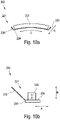
- Figures 10a and 10b show a schematic front and side view of an exemplary embodiment of a first air conduction unit 321. The illustrations and corresponding description also apply accordingly to the second and third air conduction units 222, 223.
- the first air guiding unit 221 has a main extension direction in the circumferential direction U.
- the first air guiding unit 221 comprises a base element 224 with which the air guiding unit is arranged on the cooling unit 210 .
- an air guiding element 225 extends outwards at an acute angle in the axial direction A and radial direction R, starting from the base element 224 in the operating state of the wind turbine.
- the airfoil extends in the circumferential direction between two flanges 226 .
- the flanges extend outwards in the circumferential direction U and radial direction R, starting from the base element 224 .
- a damping unit 230 is also provided, which is arranged between the base element 224 and the cooling unit 210 when the wind energy installation 100 is in operation.
- FIG. 11 shows a schematic flowchart of an exemplary method 1000 for producing a generator of a wind energy installation 100 with an air cooling device 200.
- the method 1000 initially comprises providing 1010 a cooling unit 210 of a generator and an air guiding device 220, which has a first and/or second and/or third stationary air guiding unit 221, 222, 223 designed as a partial ring segment.
- the method 1000 comprises arranging 1020 the air guiding device 220 on a cooling unit outer surface 210a, with the cooling unit 210 preferably having a plurality of cooling ribs with a main extension in an axial direction A, which are arranged at a distance in a circumferential direction U orthogonal to the axial direction A , and the air guiding device 220 preferably has a main extension essentially in a circumferential direction U, orthogonal to the axial direction A.
- the method 1000 includes attaching 1030 the air shroud 220 to the cooling unit exterior surface 210a.
- the step of fastening 1030 the air guiding device 220 to the cooling unit outer surface 210a includes in particular a material connection.
- the material connection is preferably a welded connection.
- the step of fastening 1030 includes a non-positive connection.
- the non-positive connection is in particular a screw and/or magnetic connection.
- the step of fastening 1030 additionally or alternatively includes a positive connection of the air guiding device 220 to the cooling unit 210.
- the positive connection is realized in particular by a hook connection.
- the step of attaching 1030 the air guiding device 220 to the cooling unit outer surface 210a can also preferably involve a material connection, in particular a welded connection, and/or a non-positive connection, in particular a screw connection and/or a magnetic connection, and/or a positive connection, in particular a hook and /or snap connection, of adjacently arranged partial ring segments of a first air guiding unit 221, so that they form a first air guiding unit 221 designed as a ring or partial ring.
- a material connection in particular a welded connection
- a non-positive connection in particular a screw connection and/or a magnetic connection
- a positive connection in particular a hook and /or snap connection
- the step of attaching 1030 the air guiding device 220 to the cooling unit outer surface 210a can preferably be a material connection, in particular a welded connection, and/or a non-positive connection, in particular a screw connection and/or a magnetic connection, and/or a form-fit connection, in particular a hook and /or snap connection, of adjacently arranged partial ring segments of a second air conduction unit 222, so that they form a second air conduction unit 222 designed as a ring or partial ring.
- the step of attaching 1030 the air guiding device 220 to the cooling unit outer surface 210a can preferably be a material connection, in particular a welded connection, and/or a non-positive connection, in particular a screw connection and/or a magnetic connection, and/or a form-fit connection, in particular a hook and /or snap connection, of adjacently arranged partial ring segments of a third air guiding unit 223, so that these form a third air guiding unit 223 designed as a ring or partial ring.
- the method 100 comprises the step of arranging 1040 a damping unit 230 between the air guiding device 220 and the cooling unit 210 .
- the method 2000 for producing the wind turbine 100 comprises the step of providing 2010 a rotation unit 310 of an aerodynamic rotor 106 of the wind turbine 100 with a rotation unit outer surface 310a, along which the wind W during operation of the wind turbine 100 flows. Furthermore, the method 2000 includes arranging 2020 one or more air guiding units 320 on the rotating unit outer surface 310a of the rotating unit 310 between the connections or the through-openings. Furthermore, the method 2000 includes fastening 2030 the rotation unit 310 to a generator or a generator produced according to the method 1000 described above.
- the figures 13 and 14 each show a schematic side view of a generator with a further exemplary embodiment of an air cooling device 200.
- FIG 13 shows a preferred development of the air cooling device 200, in which the air guiding device 220 extends in the operating state in the axial direction A between an air guiding leading edge 220a and an air introducing edge 220b, the air guiding leading edge 220a being arranged upstream relative to the air feeding edge 220b with respect to the wind W.
- the cooling unit leading edge 211a is arranged in the axial direction A between the air-guiding leading edge 220a and the air-introducing edge 220b. That is, the cooling unit leading edge 211a is disposed downstream of the air guide leading edge 220a and upstream of the air introducing edge 220b in the flow direction of the wind W.
- the cooling unit outer surface 210a starting from the cooling unit inflow edge 211a, extends in the axial direction A between the first and second end 211, 212 of the cooling unit 210 with a cooling unit cooling length L extends.
- the air guiding device 220 is arranged in such a way that the distance D between the air guiding leading edge 220a and the cooling unit leading edge 211a corresponds to approximately one third of the cooling unit cooling length L.
- figure 14 12 shows an embodiment of an air cooling device 200 with a fourth air guiding unit 227 which, starting from the cooling unit outer surface 227, extends outwards at an obtuse angle in the radial direction R.
- the fourth air guiding unit 227 is arranged on the cooling unit outer surface 210a in such a way that it opens at the obtuse angle in the direction of the oncoming wind W.
- the fourth air guiding unit 227 in this embodiment is arranged on the cooling unit outer surface 210a in such a way that it forms an acute angle on the side facing away from the wind W.
Landscapes
- Engineering & Computer Science (AREA)
- Life Sciences & Earth Sciences (AREA)
- Sustainable Energy (AREA)
- Sustainable Development (AREA)
- Chemical & Material Sciences (AREA)
- Combustion & Propulsion (AREA)
- Mechanical Engineering (AREA)
- General Engineering & Computer Science (AREA)
- Power Engineering (AREA)
- Physics & Mathematics (AREA)
- Thermal Sciences (AREA)
- Motor Or Generator Cooling System (AREA)
Abstract
Description
- Die Erfindung betrifft eine Luftkühlvorrichtung zur Luftkühlung eines Generators einer Windenergieanlage mittels Wind, umfassend eine Kühleinheit des Generators mit einer Kühleinheits-Außenfläche, welche der Wind zur Luftkühlung des Generators im Betrieb der Windenergieanlage anströmt. Ferner betrifft die Erfindung einen Generator einer Windenergieanlage.
- Weiterhin betrifft die Erfindung eine Luftführungsvorrichtung zur Bereitstellung von Wind zur Luftkühlung an einer Kühleinheit eines Generators einer Windenergieanlage, umfassend eine Rotationseinheit eines aerodynamischen Rotors der Windenergieanlage mit einer Rotationseinheits-Außenfläche, entlang welcher der Wind im Betrieb der Windenergieanlage strömt, wobei die Rotationseinheit Anschlüsse zur Befestigung und/oder Durchgangsöffnungen zur Durchführung von Rotorblättern des aerodynamischen Rotors aufweist. Ferner betrifft die Erfindung eine Windenergieanlage.
- Schließlich betrifft die Erfindung ein Verfahren zur Herstellung eines Generators einer Windenergieanlage mit einer Luftkühlvorrichtung und ein Verfahren zur Herstellung einer Windenergieanlage.
- Windenergieanlagen sind bekannt. Ein derzeit gängiger Typ einer Windenergieanlage ist eine sogenannte Horizontalachsenwindenergieanlage mit üblicherweise drei Rotorblättern. Solche Windenergieanlagen weisen zunehmend eine größere Bauform auf, nämlich insbesondere höhere Naben- oder Achshöhen und größere Rotordurchmesser mit entsprechend größerem Generator und größerer Einspeiseleistung. Größere Generatoren erfordern höhere Kühlleistungen, um den Generator mit einer optimalen Betriebstemperatur zu betreiben.
- Es ist bekannt, Generatoren von Windenergieanlagen durch eine aktive Kühleinheit mittels einem Kühlmedium, beispielsweise Luft oder Kühlflüssigkeit, zu kühlen. Hierzu erzeugen aktive Kühleinheiten einen Kühlmediumstrom, beispielsweise einen Luftstrom, der entlang der zu kühlenden Flächen des Generators geführt wird. Ein solcher Luftstrom wird beispielsweise mit einem Lüfter erzeugt. Alternativ kann zur Kühlung eines Generators Kühlflüssigkeit durch Rohre geführt werden, welche die Wärme abtransportieren. Mit solchen aktiven Kühleinheiten lassen sich Generatoren zwar mit einer optimalen Betriebstemperatur betreiben. Allerdings sind Windenergieanlagen mit solch aktiven Kühleinheiten einerseits in der Herstellung und andererseits im Betrieb, insbesondere hinsichtlich Instandhaltungs- und Wartungsarbeiten, teuer.
- Es ist auch bekannt, Generatoren von Windenergieanlagen passiv durch Wind, d.h. einen Luftstrom, zu kühlen. Hierzu ist vorgesehen, dass eine Kühleinheit des Generators von dem Wind angeströmt wird, welcher auch für die Energieerzeugung durch die Windenergieanlagen genutzt wird. Allerdings lassen sich Generatoren gängiger Windenergieanlage mit Wind nur unzureichend passiv kühlen. Üblicherweise reicht der Wind nicht aus, um Generatoren mit einer optimalen Betriebstemperatur zu betreiben.
- Das Deutsche Patent- und Markenamt hat in der Prioritätsanmeldung zu vorliegender Anmeldung folgenden Stand der Technik recherchiert:
DE 103 51 844 A1 ,DE 10 2007 042 338 A1 ,US 8 047 774 B2 ,EP 2 546 595 A1 ,CN 104956075 A . - Der Erfindung liegt daher die Aufgabe zugrunde, eine Luftkühlvorrichtung, einen Generator, eine Luftführungsvorrichtung, eine Windenergieanlage und eine Verfahren zur Herstellung eines Generators sowie einer Windenergieanlage bereitzustellen, welche die genannten Probleme adressiert. Insbesondere liegt der Erfindung die Aufgabe zugrunde, eine Luftkühlvorrichtung, einen Generator, eine Luftführungsvorrichtung, eine Windenergieanlage und eine Verfahren zur Herstellung eines Generators sowie einer Windenergieanlage bereitzustellen, welche einen Betrieb eines Generators einer Windenergieanlage mit einer optimalen Betriebstemperatur ermöglicht. Ferner liegt der Erfindung in bevorzugter Weise die Aufgabe zugrunde, eine Luftkühlvorrichtung, einen Generator, eine Luftführungsvorrichtung, eine Windenergieanlage und eine Verfahren zur Herstellung eines Generators sowie einer Windenergieanlage bereitzustellen, welche eine kostengünstigere Herstellung und einen kotengünstigeren Betrieb einer Windenergieanlage ermöglicht.
- Die Aufgabe wird gemäß einem Aspekt der Erfindung gelöst durch eine Luftkühlvorrichtung zur Luftkühlung eines Generators einer Windenergieanlage mittels Wind, umfassend eine Luftleitvorrichtung, die an der Kühleinheit angeordnet ist und sich ausgehend von der Kühleinheits-Außenfläche in einer Radialrichtung nach außen erstreckt und ausgebildet ist, in einem Betriebszustand der Windenergieanlage den Wind zur Luftkühlung in der Radialrichtung nach innen in Richtung der Kühleinheit zu leiten.
- Die Erfindung beruht auf der Erkenntnis, dass sich der Wind, der die Windenergieanlage an- und umströmt, durch eine Luftleitvorrichtung in Richtung der Kühleinheit eines Generators leiten lässt. Die Luftleitvorrichtung hat den Effekt, den Wind zu beschleunigen, der somit mit einer höheren Geschwindigkeit an der Kühleinheit entlang strömt und eine bessere Kühlwirkung erzielt. Ferner hat die Luftleitvorrichtung insbesondere den Effekt, dass der Wind in eine Radialrichtung abgelenkt wird, die den Wind in ein Inneres der Kühleinheit leitet. Hierdurch lässt sich ein Generator mit einer optimalen Betriebstemperatur, jedenfalls aber näher an der optimalen Betriebstemperatur betreiben. Insbesondere lässt sich durch die Luftleitvorrichtung die Kühleinheit, d.h. der Generator, gleichmäßig kühlen. Dies führt insbesondere in Axialrichtung und Umfangsrichtung zu einem geringen Temperaturgefällte, was wiederum den Wirkungsgrad eines Generators erhöht. Ferner hat eine solch passives Kühlen den Vorteil, dass der Energieeinsatz für aktives Kühlen minimiert oder gar vollständig vermieden wird, was wiederum Kosten einspart.
- Im Betriebszustand erstreckt sich die Windenergieanlage ausgehend von einem Fundament mit einem Turm bis zu einer Gondel, an welcher der aerodynamische Rotor mit den Rotorblättern angeordnet ist. Die Windenergieanlage, bzw. der Turm, erstrecken sich im Betriebszustand in einer im Wesentlichen vertikalen Richtung. Insofern bildet das Fundament ein unteres Ende der Windenergieanlage und die Gondel mit dem aerodynamischen Rotor ein oberes Ende. Innerhalb der Gondel ist der Generator angeordnet, welcher mit dem aerodynamischen Rotor gekoppelt ist.
- Die Gondel kann im Betriebszustand der Windenergieanlage um eine Gondelachse drehbar gelagert sein. Die Gondelachse ist in der Regel im Wesentlichen vertikal ausgerichtet. Aufgrund der drehbaren Lagerung der Gondel um die Gondelachse lässt sich der aerodynamische Rotor der Windenergieanlage in Abhängigkeit der Windrichtung ausrichten. Der in der Gondel angeordnete Generator weist einen Stator mit einer Drehachse auf, um welche ein Rotor des Generators relativ zum Stator des Generators drehbar gelagert ist, um elektrische Energie aus kinetischer Energie zu erzeugen. In einer bevorzugten Ausführungsform ist der Generator als hochpoliger, insbesondere fremderregter, Synchrongenerator ausgebildet. Im Betriebszustand der Windenergieanlage ist die Drehachse vorzugsweise im Wesentlichen orthogonal zu der Gondelachse ausgerichtet. Insbesondere ist die Drehachse gegenüber der Gondelachse leicht geneigt ausgerichtet.
- In dem Betriebszustand der Windenergieanlage ist die Kühleinheit vorzugsweise an dem Generator angeordnet. Insbesondere ist die Kühleinheit in dem Betriebszustand der Windenergieanlage an einer Außenfläche des Generators angeordnet. Ferner kann bevorzugt sein, dass die Kühleinheit in dem Betriebszustand der Windenergieanlage an der Gondel befestigt ist. Es ist jedenfalls bevorzugt, dass die Kühleinheit in dem Betriebszustand der Windenergieanlage mit dem Generator thermisch gekoppelt ist.
- Im vorliegenden Text beziehen sich Positions- und Lageangaben, wie beispielsweise "oben" und "unten" oder "außen" und "innen" oder "radial", "axial" oder "umfang", sofern nicht anders ausgeführt auf den Betriebszustand einer Windenergieanlage, insbesondere auf die Drehachse des Generators. Insbesondere ist zu verstehen, dass eine Axialrichtung im Wesentlichen einer Ausrichtung bzw. Orientierung der Drehachse des Generators entspricht.
- Beim Transport und/oder bei Wartungs- und/oder Instandhaltungsarbeiten an der Windenergieanlage und/oder dem Generator und/oder der Luftkühlvorrichtung und/oder Turm kann die Ausrichtung der Achsen, insbesondere zueinander, von der Ausrichtung der Achsen im Betriebszustand der Windenergieanlage abweichen.
- Die Kühleinheit erstreckt sich in der Axialrichtung mit einer Kühleinheits-Länge zwischen einem ersten und zweiten Ende. Die Axialrichtung entspricht vorzugsweise einer Orientierung der Drehachse des Generators. In Umfangsrichtung, orthogonal zu der Axialrichtung, erstreckt sich die Kühleinheit insbesondere mit einer Kühleinheits-Breite zwischen einer ersten und zweiten Seite. Orthogonal zu der Axialrichtung und Umfangsrichtung erstreckt sich die Kühleinheit zwischen einer Kühleinheits-Innenfläche und der Kühleinheits-Außenfläche mit einer Kühleinheits-Höhe.
- Vorzugsweise ist die Kühleinheits-Höhe kleiner als die Kühleinheits-Breite. Ferner ist bevorzugt, dass die Kühleinheits-Breite kleiner ist als die Kühleinheits-Länge. Vorzugsweise ist die Kühleinheit als teilringförmiges Kühlsegment ausgebildet. Es kann auch bevorzugt sein, dass die Kühleinheit ein oder mehrere teilringförmige Kühlsegmente umfasst.
- Die Kühleinheits-Außenfläche ist vorzugsweise eben ausgebildet. Es kann auch bevorzugt sein, dass die Kühleinheits-Außenfläche profiliert ausgebildet ist. Insbesondere kann die Kühleinheits-Außenfläche Erhebungen oder Erstreckungen aufweisen, die sich in der Radialrichtung nach außen erstrecken, und/oder Ausnehmungen aufweisen, die sich in der Radialrichtung nach innen erstrecken. Insbesondere kann die Kühleinheits-Außenfläche ein rippenförmiges und/oder wellenförmiges und/oder rohrförmiges Profil und/oder kanalförmiges Profil aufweisen.
- Im Betriebszustand ist die Kühleinheit an einer Außenseite des Generators angeordnet. Zur Kühlung des Generators ist dieser mit der Kühleinheit thermisch gekoppelt. In bevorzugter Weise bildet die Gondel die Kühleinheit aus oder nimmt diese an der Außenseite auf. Insbesondere ist vorgesehen, dass die Gondel eine oder mehrere Öffnungen aufweist, in denen die Kühleinheit angeordnet ist. Die eine oder mehreren Öffnungen können ringförmig oder teilringförmig ausgebildet sein.
- Insbesondere kann eine Außenseite eines Stators und/oder eines Generators die Kühleinheit ausbilden oder sein.
- Die Luftleitvorrichtung ist ausgebildet, in dem Betriebszustand der Windenergieanlage den Wind zur Luftkühlung in der Radialrichtung nach innen in Richtung der Kühleinheit zu leiten. Hierzu ist die Luftleitvorrichtung vorzugsweise gegenüber der Kühleinheits-Außenfläche geneigt angeordnet. Insbesondere ist die Luftleitvorrichtung derart angeordnet, dass diese einen oder mehrere Luftleitkanäle ausbilden, welche den Wind zur Luftkühlung in der Radialrichtung nach innen in Richtung der Kühleinheit leiten. Insbesondere sind die einen oder mehrere Luftleitkanäle im Betriebszustand der Windenergieanlage zur Windrichtung ausgerichtet, so dass der Wind, welcher die Windenergieanlage umströmt in den einen oder die mehreren Luftleitkanäle eintritt.
- Es kann bevorzugt sein, dass die Luftleitvorrichtung, die sich ausgehend von der Kühleinheits-Außenfläche in der Radialrichtung nach außen erstreckt, zu der Kühleinheit beabstandet angeordnet ist. Insbesondere kann die Luftleitvorrichtung zu der Kühleinheit in der Radialrichtung beabstandet angeordnet sein. Insbesondere weist die Luftleitvorrichtung in der Radialrichtung einen Abstand auf, welcher mindestens 0%, 1%, 5%, 10%, 20%, 30%, 40%, 50%, 100%, 150% oder 200% der Kühleinheits-Länge entspricht und/oder maximal 0%, 1%, 5%, 10%, 20%, 30%, 40%, 50%, 100%, 150% oder 200% der Kühleinheits-Länge entspricht.
- Alternativ kann es bevorzugt sein, dass die Kühleinheit die Luftleitvorrichtung integral ausbildet. Insbesondere ist auch bevorzugt, dass die Luftleitvorrichtung an der Kühleinheits-Außenfläche befestigt ist. Vorzugsweise ist die Luftleitvorrichtung kraft- und/oder stoff- und/oder formschlüssig mit der Kühleinheit verbunden. Insbesondere kann bevorzugt sein, dass die Luftleitvorrichtung mit der Kühleinheit verschweißt ist. Alternativ oder ergänzend kann bevorzugt sein, die Luftleitvorrichtung mit der Kühleinheit zu verschrauben.
- Gemäß einer bevorzugten Ausführungsform der Luftkühlvorrichtung ist vorgesehen, dass die Luftleitvorrichtung eine erste Luftleiteinheit aufweist, die sich ausgehend von der Kühleinheits-Außenfläche spitzwinklig in der Radialrichtung nach außen erstreckt und/oder mit der Kühleinheit einen konvergierenden ersten Luftleitkanal bildet, der ausgebildet ist, in dem Betriebszustand der Windenergieanlage den Wind zur Luftkühlung in der Radialrichtung nach innen in Richtung der Kühleinheit zu leiten. Alternativ oder ergänzend ist bevorzugt vorgesehen, dass die Kühleinheit mehrere Kühlrippen mit einer Haupterstreckung in einer Axialrichtung aufweist, die in einer Umfangsrichtung orthogonal zu der Axialrichtung beabstandet angeordnet sind, und die Luftleitvorrichtung eine Haupterstreckung im Wesentlichen in der Umfangsrichtung aufweist.
- Die erste Luftleiteinheit ist an der Kühleinheits-Außenfläche derart angeordnet, dass diese sich in einem spitzen Winkel bzw. spitzwinklig in der Radialrichtung nach außen erstreckt. Ein spitzer Winkel liegt zwischen mindesten einschließlich 0° und maximal einschließlich 90°. Insbesondere bewirkt die spitzwinklige Anordnung der ersten Luftleiteinheit, dass der in dem Betriebszustand der Windenergieanlage in Wesentlichen axial anströmende Wind in der Radialrichtung nach innen in Richtung zu der Kühleinheit umgeleitet wird.
- Die erste Luftleiteinheit ist vorzugsweise teilringförmig oder ringförmig ausgebildet. Die erste Luftleiteinheit erstreckt sich in der Axialrichtung mit einer ersten Länge, in der Umfangsrichtung mit einer ersten Breite und in der Radialrichtung mit einer ersten Höhe. Vorzugsweise ist die erste Breite größer als die erste Länge und/oder die erste Höhe. Vorzugsweise weist die erste Luftleiteinheit ein lineares Profil auf. Ein lineares Profil weist insbesondere keine Wölbung auf. Es kann bevorzugt sein, dass die erste Luftleiteinheit ein geschwungenes Profil und/oder Profil mit Kanten aufweist. Vorzugsweise weist die Kante des Profils der ersten Luftleiteinheit eine Kantenlänge auf, die vorzugsweise mindestens 0 % und maximal 200 % der Kühleinheits-Länge entspricht, die sich zwischen dem ersten Ende und zweiten Ende erstreckt. Insbesondere kann das Profil der ersten Luftleiteinheit auch S-förmig ausgebildet sein. Insbesondere kann das Profil der ersten Luftleiteinheit konvexe und/oder konkave Profilabschnitte aufweisen.
- Die spitzwinklige Anordnung der ersten Luftleiteinheit an der Kühleinheits-Außenfläche hat den Vorteil, den Wind, der die Windenergieanlage in deren Betriebszustand umströmt, besonders effizient in Richtung der radial innenliegenden Kühleinheit zu leiten. Insbesondere lässt sich Wind in ausreichender Menge und einer geeigneten Geschwindigkeit zur Kühlung an der Kühleinheit bereitstellen.
- Die erste Luftleiteinheit ist an der Kühleinheit derart angeordnet, dass diese mit der Kühleinheits-Außenfläche einen ersten Luftleitkanal bildet, der konvergiert. Der Luftleitkanal weist eine Eintrittsöffnung auf, durch welche der Wind im Betriebszustand der Windenergieanlage eintritt, und eine Austrittsöffnung auf, durch welche der Wind im Betriebszustand der Windenergieanlage austritt. Bei einem konvergierenden Luftleitkanal nimmt der Querschnitt des Kanals in Strömungsrichtung ab. Bei einem konvergierenden Luftleitkanal kann die Eintrittsöffnung kleiner sein als die Austrittsöffnung. Insbesondere konvergiert der erste Luftleitkanal in der Axialrichtung. In dieser bevorzugten Ausführungsform ist der erste konvergierende Luftleitkanal ringförmig ausgebildet. Es kann aber auch bevorzugt sein, den ersten konvergierenden Luftleitkanal rohrförmig auszubilden. In der vorliegenden Ausführungsform weist der erste konvergierende Luftleitkanal einen in der Umfangsrichtung konstanten Querschnitt auf.
- Ein solch konvergierender Luftleitkanal hat den Vorteil, dass der Wind in Richtung der Kühleinheit beschleunigt wird, was die Kühlleistung der Luftkühlvorrichtung nochmals verbessert.
- Die Kühleinheit weist mehrere Kühlrippen auf, die in der Umfangsrichtung beabstandet zueinander angeordnet sind. Die in Umfangsrichtung jeweils benachbart angeordneten Kühlrippen definieren insbesondere einen Lüftungskanal, der eine Haupterstreckung in der Axialrichtung aufweist. In den Lüftungskanälen kann die durch das erste Luftleiteinheit zugeführte Luft strömen zur Kühlung des Generators bzw. der Kühleinheit.
- Die mit Kühlrippen ausgebildete Kühleinheit hat den Effekt, dass die Fläche, über welche die Wärme des Generators abgeführt werden kann, vergrößert wird. Ferner haben die Kühlrippen den Effekt, dass diesen den zugeführten Wind in Axialrichtung über die Kühleinheitslänge für eine verbesserte Kühlungswirkung leiten. Insbesondere definieren die in Umfangsrichtung beabstandet angeordneten Kühlrippen Lüftungskanäle, welche den zugeführten Wind nochmals beschleunigen können und die Kühlleistung der Luftkühlvorrichtung weiter verbessern.
- Nach einer weiteren bevorzugten Fortbildung umfasst die Luftleitvorrichtung eine zweite und/oder dritte Luftleiteinheit auf.
- Die zweite Luftleiteinheit ist in der Axialrichtung gegenüber der ersten Luftleiteinheit versetzt angeordnet und erstreckt sich ausgehend von der Kühleinheits-Außenfläche spitzwinklig in der Radialrichtung nach außen und/oder bildet mit der der Kühleinheit einen konvergierenden zweiten Luftleitkanal, der ausgebildet ist, in dem Betriebszustand der Windenergieanlage den Wind zur Luftkühlung in der Radialrichtung nach innen in Richtung der Kühleinheit zu leiten.
- Die dritte Luftleiteinheit ist in der Axialrichtung gegenüber der ersten und/oder zweiten Luftleiteinheit versetzt angeordnet und erstreckt sich ausgehend von der Kühleinheits-Außenfläche spitzwinklig in der Radialrichtung nach außen und/oder bildet mit der der Kühleinheit einen konvergierenden dritten Luftleitkanal, der ausgebildet ist, in dem Betriebszustand der Windenergieanlage den Wind zur Luftkühlung in der Radialrichtung nach innen in Richtung der Kühleinheit zu leiten.
- Die zweite und/oder dritte Luftleiteinheit sind an der Kühleinheits-Außenfläche derart angeordnet, dass diese sich in einem spitzen Winkel bzw. spitzwinklig in der Radialrichtung nach außen erstrecken. Insbesondere bewirkt die spitzwinklige Anordnung der zweiten und/oder dritten Luftleiteinheit, dass der in dem Betriebszustand der Windenergieanlage in Wesentlichen axial anströmende Wind in der Radialrichtung nach innen in Richtung zu der Kühleinheit umgeleitet wird.
- Die zweite und/oder dritte Luftleiteinheit sind vorzugsweise teilringförmig oder ringförmig ausgebildet. Die zweite und/oder dritte Luftleiteinheit erstrecken sich in der Axialrichtung mit einer zweiten und/oder dritten Länge, in der Umfangsrichtung mit einer zweiten und/oder dritten Breite und in der Radialrichtung mit einer zweiten und/oder dritten Höhe. Vorzugsweise ist die zweite bzw. dritte Breite größer als die zweite bzw. dritte Länge und/oder die zweite bzw. dritte Höhe. Vorzugsweise weist die zweite und/oder dritte Luftleiteinheit ein lineares Profil auf. Es kann bevorzugt sein, dass die zweite und/oder dritte Luftleiteinheit ein geschwungenes Profil und/oder Profil mit Kanten aufweist. Vorzugsweise weist die Kante des Profils der zweiten und/oder dritten Luftleiteinheit eine Kantenlänge auf, die vorzugsweise mindestens 0 % und maximal 200 % der Kühleinheits-Länge entspricht, die sich zwischen dem ersten Ende und zweiten Ende erstreckt. Insbesondere kann das Profil der zweiten und/oder dritten Luftleiteinheit auch S-förmig ausgebildet sein. Insbesondere kann das Profil der zweiten und/oder dritten Luftleiteinheit konvexe und/oder konkave Profilabschnitte aufweisen.
- Die spitzwinklige Anordnung der zweiten und/oder dritten Luftleiteinheit an der Kühleinheits-Außenfläche hat den Vorteil, den Wind, der die Windenergieanlage in deren Betriebszustand umströmt, besonders effizient in Richtung der radial innenliegenden Kühleinheit zu leiten. Insbesondere lässt sich Wind in ausreichender Menge und einer geeigneten Geschwindigkeit zur Kühlung an der Kühleinheit bereitstellen.
- Die zweite und/oder dritte Luftleiteinheit ist an der Kühleinheit derart angeordnet, dass diese mit der Kühleinheits-Außenfläche einen zweiten und/oder dritten Luftleitkanal bildet, der jeweils konvergiert. Der Luftleitkanal weist eine Eintrittsöffnung auf, durch welche der Wind im Betriebszustand der Windenergieanlage eintritt, und eine Austrittsöffnung auf, durch welche der Wind im Betriebszustand der Windenergieanlage austritt. Insbesondere konvergiert der zweite und/oder dritte Luftleitkanal in der Axialrichtung. In dieser bevorzugten Ausführungsform ist der zweite und/oder dritte konvergierende Luftleitkanal ringförmig ausgebildet. Es kann aber auch bevorzugt sein, den zweiten und/oder dritten konvergierenden Luftleitkanal rohrförmig auszubilden. In der vorliegenden Ausführungsform weist der zweite und/oder dritte konvergierende Luftleitkanal einen in der Umfangsrichtung konstanten Querschnitt auf.
- Solch konvergierende Luftleitkanäle haben den Vorteil, dass der Wind in Richtung der Kühleinheit beschleunigt wird, was die Kühlleistung der Luftkühlvorrichtung nochmals verbessert.
- Die erste Luftleiteinheit ist gegenüber der zweiten und/oder dritten Luftleiteinheit versetzt angeordnet. Vorzugsweise ist die dritte Luftleiteinheit zwischen der ersten und zweiten Luftleiteinheit angeordnet. Insbesondere ist die erste Luftleiteinheit gegenüber der zweiten und/oder dritten Luftleiteinheit mit einem Abstand von mindestens 0%, 10%, 20%, 30%, 40%, 50%, 100%, 200%, 300%, 400%, 500% oder 1000% der ersten Länge der ersten Luftleiteinheit beabstandet angeordnet. Ergänzend oder alternativ ist die erste Luftleiteinheit gegenüber der zweiten und/oder dritten Luftleiteinheit mit einem Abstand von maximal 0%, 10%, 20%, 30%, 40%, 50%, 100%, 200%, 300%, 400%, 500% oder 1000% der ersten Länge der ersten Luftleiteinheit beabstandet angeordnet.
- Vorzugsweise ist die erste Luftleiteinheit beabstandet zu dem ersten Ende angeordnet. Es kann bevorzugt sein, dass die erste Luftleiteinheit an dem ersten Ende angeordnet ist. Vorzugsweise ist die erste Luftleiteinheit mit einem Abstand von mindestens 0%,10%, 20%, 30%, 40%, 50% oder 60% der Kühleinheits-Länge von dem ersten Ende der Kühleinheit beabstandet angeordnet. Ergänzend oder alternativ ist die erste Luftleiteinheit mit einem Abstand von maximal 0%,10%, 20%, 30%, 40%, 50% oder 60% der Kühleinheits-Länge von dem ersten Ende der Kühleinheit beabstandet angeordnet.
- Ferner kann bevorzugt sein, dass die zweite Luftleiteinheit beabstandet zu dem zweiten Ende angeordnet ist.
- Eine Luftleitvorrichtung aufweisend mehrere Luftleiteinheiten hat den Vorteil, dass die Luftleiteinheiten in Abhängigkeit des Anströmprofils des Windes an der Kühleinheit angeordnet werden können. Das Anströmprofil kann vom Typ der Windenergieanlage abhängen. Ferner lässt sich hierdurch die Menge an Wind erhöhen, welche der Kühleinheit zugeführt werden kann. Dies erhöht die Kühlleistung und ermöglicht einen Betrieb der Windenergieanlage mit einer optimalen Betriebstemperatur. Ferner hat eine solche Anordnung den Vorteil, dass die Kühleinheit und mithin der Generator in Umfangsrichtung und Axialrichtung gleichmäßig gekühlt werden. Insbesondere lässt sich durch die Anordnung ein Temperaturgefälle in Axialrichtung und/oder Umfangsrichtung an der Kühleinheit bzw. dem Generator minimieren.
- Gemäß einer weiteren bevorzugten Fortbildung der Luftkühlvorrichtung ist vorgesehen, dass die erste und/oder zweite und/oder dritte Luftleiteinheit aus einem oder mehreren Teilringsegmenten ausgebildet sind.
- Diese bevorzugte Ausführungsform hat den Vorteil, dass die Luftkühlvorrichtung besonders einfach und kostengünstig montiert werden kann. Insbesondere lassen sich trotz der bestehenden transportbedingten Größenbeschränkungen hierdurch auch Luftkühlvorrichtungen für Generatoren mit einem besonders großen Durchmesser bereitstellen und passiv kühlen.
- Ferner ist nach einer bevorzugten Ausführungsform vorgesehen, dass sich ausgehend von der Kühleinheits-Außenfläche die erste Luftleiteinheit mit einem ersten spitzen Winkel erstreckt, die zweite Luftleiteinheit mit einem zweiten spitzen Winkel erstreckt und die dritte Luftleiteinheit mit einem dritten spitzen Winkel erstreckt, wobei der erste und/oder zweite und/oder dritte spitze Winkel gleich sind, und/oder der erste spitze Winkel kleiner ist als der zweite und/oder dritte spitze Winkel, und/oder der erste spitze Winkel größer ist als der zweite und/oder dritte spitze Winkel, und/oder sich ausgehend von der Kühleinheits-Außenfläche die erste Luftleiteinheit in der Radialrichtung mit einer ersten Höhe erstreckt, die zweite Luftleiteinheit in der Radialrichtung mit einer zweiten Höhe erstreckt und die dritte Luftleiteinheit in der Radialrichtung mit einer dritten Höhe erstreckt, wobei der erste und/oder zweite und/oder dritte Höhe gleich sind und/oder die erste Höhe kleiner ist als die zweite und/oder dritte Höhe, und/odersich ausgehend von der Kühleinheits-Außenfläche die erste Luftleiteinheit in der Axialrichtung mit einer ersten Länge erstreckt, die zweite Luftleiteinheit in der Axialrichtung mit einer zweiten Länge er-streckt und die dritte Luftleiteinheit in der Axialrichtung mit einer dritten Länge erstreckt, wobei die erste und/oder zweite und/oder dritte Länge gleich sind, und/oder die erste Länge kleiner ist als die zweite und/oder dritte Länge, und/oder die erste Länge größer ist als die zweite und/oder dritte Länge.
- Der erste und/oder zweite und/oder dritte spitze Winkel entsprechen mindestens 0°, 10°, 15°, 20°, 25°, 30°, 35°, 40°, 45°, 50°, 60°, 70°, 80°, 90° oder mehr und maximal 0°, 10°, 15°, 20°, 25°, 30°, 35°, 40°, 45°, 50°, 60°, 70°, 80° oder 90°. Vorzugsweise ist der erste spitze Winkel kleiner als der zweite und/oder dritte spitze Winkel. Ferner ist bevorzugt, dass der dritte spitze Winkel kleiner ist als der zweite spitze Winkel. Insbesondere ist bevorzugt, dass der erste spitze Winkel 20° oder 30° beträgt. Ferner ist bevorzugt, dass der zweite und/oder dritte spitze Winkel 30° oder 35° beträgt. Ferner kann bevorzugt sein, dass der erste spitze Winkel größer ist als der zweite und/oder dritte spitze Winkel. Weiterhin kann auch bevorzugt sein, dass der dritte spitze Winkel größer ist als der zweite spitze Winkel. Ferner kann bevorzugt sein, dass erste und/oder zweite und/oder dritte spitze Winkel gleich sind.
- Insbesondere ist zu verstehen, dass die erste Luftleiteinheit und/oder die zweite Luftleiteinheit und/oder die dritte Luftleiteinheit sich ausgehend von der Kühleinheits-Außenfläche in einem spitzen Winkel erstreckt, so dass Wind zwischen die Kühleinheits-Außenfläche und die erste Luftleiteinheit und/oder die zweite Luftleiteinheit und/oder die dritte Luftleiteinheit geleitet wird. Insbesondere öffnet sich die erste Luftleiteinheit und/oder die zweite Luftleiteinheit und/oder die dritte Luftleiteinheit ausgehend von der Kühleinheits-Außenfläche in einem spitzen Winkel in Richtung des anströmenden Windes. Es ist insbesondere zu verstehen, dass zwischen der Kühleinheits-Außenfläche und der ersten Luftleiteinheit und/oder der zweiten Luftleiteinheit und/oder der dritten Luftleiteinheit ein erster und/oder zweiter und/oder dritter stumpfer Winkel ausgebildet wird, der in dem Betriebszustand von der Anströmrichtung des Windes abgewandt ist. Insbesondere bilden der erste spitze Winkel und der erste stumpfe Winkel zusammen 180° und/oder bilden der zweite spitze Winkel und der zweite stumpfe Winkel zusammen 180° und/oder bilden der dritte spitze Winkel und der dritte stumpfe Winkel zusammen 180°. Der erste und/oder der zweite und/oder der dritte stumpfe Winkel sind größer als 90° und kleiner als 180°.
- Die erste und/oder zweite und/oder dritte Höhe entsprechen mindestens 0mm, 50mm, 100mm, 150mm, 200mm, 300mm oder mehr und maximal 0mm, 50mm, 100mm, 150mm, 200mm oder 300mm. Vorzugsweise ist die erste Höhe kleiner als die zweite und/oder dritte Höhe. Ferner ist bevorzugt, dass die dritte Höhe kleiner ist als die zweite Höhe.
- Die erste und/oder zweite und/oder dritte Länge entsprechen mindestens 0mm, 50mm, 100mm, 150mm, 200mm, 300mm oder mehr und maximal 0mm, 50mm, 100mm, 150mm, 200mm oder 300mm. Vorzugsweise ist die erste Länge kleiner als die zweite und/oder dritte Länge. Ferner ist bevorzugt, dass die dritte Länge kleiner ist als die zweite Länge. Insbesondere ist bevorzugt, dass die erste Länge 150mm beträgt. Ferner ist bevorzugt, dass die zweite und/oder dritte Länge 200mm beträgt. Ferner ist bevorzugt, dass die erste und/oder zweite und/oder dritte Länge mindestens 1%, 10%, 20%, 30%, 40% oder 50% der Kühleinheits-Länge entsprechen und/oder maximal 1%, 10%, 20%, 30%, 40% oder 50% der Kühleinheits-Länge entsprechen.
- Nach einer weiteren bevorzugten Fortbildung der Luftkühlvorrichtung ist vorgesehen, dass sich die Kühleinheit in der Axialrichtung zwischen einem ersten Ende, welche in dem Betriebszustand der Windenergieanlage bezogen auf die Windrichtung des Windes stromaufwärts angeordnet ist, und einem zweiten Ende, welche in dem Betriebszustand der Windenergieanlage bezogen auf die Wind-richtung des Windes stromaufwärts des ersten Endes angeordnet ist, erstreckt, wobei die erste Luftleiteinheit bezogen auf die Erstreckung der Kühleinheit ausgehend von dem ersten Ende in der Axialrichtung einem ersten Drittel und/oder einer ersten Hälfte der Kühleinheit angeordnet ist, und/oder die zweite Luftleiteinheit bezogen auf die Erstreckung der Kühleinheit ausgehend von dem ersten Ende in der Axialrichtung einem zweiten oder dritten Drittel und/oder einer zweiten Hälfte der Kühleinheit angeordnet ist, und/oder die dritte Luftleiteinheit bezogen auf die Erstreckung der Kühleinheit ausgehend von dem ersten Ende in der Axialrichtung einem ersten, zweiten oder dritten Drittel und/oder einer ersten oder zweiten Hälfte der Kühleinheit angeordnet ist.
- Diese Ausführungsform hat den Vorteil, dass ein Temperaturgefälle der Kühleinheit bzw. des zu kühlenden Generators in der Axialrichtung und Umfangsrichtung minimieren lässt. Dies führt in besonders bevorzugter Weise zu einem verbesserten Wirkungsgrad des Generators.
- In einer weiteren bevorzugten Ausführungsform der Luftkühlvorrichtung ist vorgesehen, dass die erste und/oder zweite und/oder dritte Luftleiteinheit jeweils aufweisen ein Basiselement, welches zur Anordnung der jeweiligen Luftleiteinheit an der Kühleinheit ausgebildet ist, und/oder ein Luftleitelement, welches sich ausgehend von dem Basiselement spitzwinklig erstreckt und mit der Kühleinheit einen konvergierenden Luftleitkanal bildet, der ausgebildet ist, in dem Betriebszustand der Windenergieanlage den Wind zur Luftkühlung in Richtung der Kühleinheit zu leiten, und/oder einen Flansch, welcher sich ausgehend von dem Basiselement winklig erstreckt und zur Verbindung von in Umfangsrichtung benachbart angeordneten Luftleiteinheiten ausgebildet ist.
- Eine solche bevorzugte Ausführungsform ermöglicht eine besonders leichte und kostengünstige Montage der Luftleitvorrichtung an der Kühleinheit. Insbesondere hat diese bevorzugte Ausführungsform den Vorteil, dass bestehend und bereits im Betrieb stehende Generatoren mit einer solchen Luftkühlvorrichtung einfach und kostengünstig nachgerüstet werden können. Ferner hat dies die Wirkung, dass der Generator sowohl in der Fabrik als auch am Aufstellort der Windenergieanlage montiert werden kann.
- Nach einer weiteren bevorzugten Ausführungsform weist die Luftkühlvorrichtung eine Dämpfungseinheit, welche zwischen der Luftleitvorrichtung und der Kühleinheit angeordnet ist.
- Ferner ist gemäß einer bevorzugten Fortbildung vorgesehen, dass sich die Luftleitvorrichtung im Betriebszustand in der Axialrichtung zwischen einer Luftleitanströmkante und einer Lufteinleitkante erstreckt, wobei die Luftleitanströmkante gegenüber der Lufteinleitkante bezogen auf den Wind stromaufwärts angeordnet ist. An der Luftleitanströmkante tritt Wind in Strömungsrichtung erstmals mit der Luftleitvorrichtung im Betriebszustand in Kontakt. Die Luftleitanströmkante weist vorzugsweise eine Haupterstreckungsrichtung in Umfangsrichtung auf. An der Lufteinleitkante wird in bevorzugter Weise der von der Luftleitvorrichtung im Betriebszustand geführte Wind an der Kühleinheits-Außenfläche in die Kühleinheit eingeleitet. Insofern ist die Lufteinleitkante vorzugsweise stromabwärts von der Luftleitanströmkante angeordnet. Insbesondere steht die ist die Luftleitvorrichtung an der Lufteinleitkante letztmalig mit dem angeströmten Wind im Kontakt, bevor dieser zur Kühlung in die Kühleinheit geleitet wird.
- Weiterhin ist nach einer bevorzugten Ausführungsform der Luftkühlvorrichtung vorgesehen, dass die Kühleinheits-Außenfläche eine Kühleinheits-Anströmkante aufweist und die Luftleitvorrichtung derart an der Kühleinheit angeordnet ist, dass die Kühleinheits-Anströmkante in der Axialrichtung zwischen der Luftleitanströmkante und der Lufteinleitkante angeordnet ist. Vorzugsweise ist die Kühleinheits-Anströmkante das erste Ende der Kühleinheit. Insbesondere ist also die Kühleinheits-Anströmkante in Strömungsrichtung des Windes stromabwärts der Luftleitanströmkante und stromaufwärts der Lufteinleitkante angeordnet. Durch diese Anordnung lässt sich die Kühlleistung in bevorzugter Weise nochmals erhöhen.
- Gemäß einer weiteren bevorzugten Fortbildung erstreckt sich die Kühleinheits-Außenfläche ausgehend von der Kühleinheits-Anströmkante in der Axialrichtung mit einer Kühleinheits-Kühllänge und der Abstand zwischen der Luftleitanströmkante und der Kühleinheits-Anströmkante beträgt mindestens 0 % der Kühleinheits-Kühllänge und maximal 100 % der Kühleinheits-Kühllänge. Insbesondere erstreckt sich die Kühleinheit zwischen dem ersten Ende und dem zweiten Ende mit der Kühleinheits-Kühllänge. Dies hat insbesondere den Vorteil, dass der Wind zur Kühlung des Generators besser zu der Kühleinheits-Außenfläche der Kühleinheit geführt werden kann. Insbesondere lässt sich hierdurch die Kühlleistung durch diese Anordnung in vorteilhafter Weise erhöhen.
- Nach einer ferner bevorzugten Fortbildung der Luftkühlvorrichtung weist die Luftleitvorrichtung eine vierte Luftleiteinheit auf, die sich ausgehend von der Kühleinheits-Außenfläche mit einem stumpfen Winkel in der Radialrichtung nach außen erstreckt. Der stumpfe Winkel ist insbesondere ein Winkel größer als 90° und kleiner als 180°. Der stumpfe Winkel ist insbesondere der Winkel zwischen der Kühleinheits-Außenfläche und der vierten Luftleiteinheit, der sich in Strömungsrichtung des Windes öffnet. Es ist insbesondere zu verstehen, dass zwischen der vierten Luftleiteinheit und der Kühleinheits-Außenfläche ein vierter spitzer Winkel ausgebildet wird, der in dem Betriebszustand von der Anströmrichtung des Windes abgewandt ist. Der vierte spitze Winkel ist vorzugsweise größer als 0° und kleiner als 90°. Insbesondere bilden der vierte spitze Winkel und der vierte stumpfe Winkel zusammen 180°.
- Dies reduziert in vorteilhafter Weise Vibrationen. Dadurch lässt sich die Schallemission minimieren. Ferner werden durch die minimierten Vibrationen die Luftkühlvorrichtung geschont, was wiederum die Lebensdauer der Luftkühlvorrichtung erhöht.
- Die Aufgabe wird gemäß einem weiteren Aspekt der Erfindung gelöst durch einen Generator einer Windenergieanlage umfassend eine zuvor beschriebene Luftkühlvorrichtung.
- Die Aufgabe wird gemäß einem Aspekt der Erfindung gelöst durch eine Luftführungsvorrichtung umfassend eine oder mehrere Luftführungseinheiten an der Rotationseinheits-Außenfläche der Rotationseinheit zwischen den Anschlüssen oder den Durchgangsöffnungen angeordnet sind, die sich ausgehend von der Rotationseinheits-Außenfläche in einer Radialrichtung nach außen erstreckt und ausgebildet ist, den Wind zur Luftkühlung des Generators zu der Kühleinheit zu leiten.
- Die Rotationseinheit ist insbesondere ein Spinner, eine Nabe oder ein sonstiges geeignetes Element des aerodynamischen Rotors einer Windenergieanlage.
- Die eine oder mehrere Luftführungseinheiten sind insbesondere schaufelförmig ausgebildet. Es kann bevorzugt sein, dass die eine oder mehrere Luftführungseinheiten ein Profil mit einer Wölbung aufweisen. Insbesondere weisen die eine oder mehrere Luftführungseinheiten ein lineares und/oder konvexes und/oder konkaves und/oder s-förmiges Profil auf. Insbesondere können die eine oder mehrere Luftführungseinheiten ein Profil mit einer Kante und/oder einen Sprung aufweisen.
- Ferner ist bevorzugt, dass die Luftführungsvorrichtung eine oder mehrere Abdeckungen aufweist. Insbesondere kann in bevorzugter Weise vorgesehen sein, dass die eine oder mehreren Luftführungseinheiten eine Abdeckung zur Führung des Windes aufweisen. Insbesondere ist die eine oder sind die mehreren Abdeckungen an einer in der Radialrichtung außenliegenden Seite der einen oder der mehreren Luftführungseinheiten angeordnet. Insbesondere ist die eine oder sind die mehreren Abdeckungen derart an der Rotationseinheit angeordnet, dass sich die eine oder die mehreren Luftführungseinheiten in der Radialrichtung zwischen der Rotationseinheits-Außenfläche der Rotationseinheit und der Abdeckung erstrecken. Es ist zu verstehen, dass die eine oder mehrere Abdeckungen mit der einen oder den mehreren Luftführungseinheiten und der Rotationseinheits-Außenfläche einen oder mehrere Luftführungskanäle ausbilden. Die Luftführungskanäle sind besonders bevorzugter Weise geeignet, den Wind, welcher die Windenergieanlage in dessen Betriebszustand an- und umströmt, in Richtung des zu kühlenden Generators, insbesondere in Richtung einer an dem Generator ausgebildeten oder angeordneten Kühleinheit, für eine verbesserte Kühlleistung zu leiten.
- Die Rotationseinheit erstreckt sich in der Axialrichtung mit einer Rotationseinheits-Länge. Die eine oder mehrere Luftführungseinheiten erstrecken sich in der Axialrichtung mit einer Luftführungseinheits-Länge. Vorzugsweise erstrecken sich die eine oder mehreren Luftführungseinheiten mit Luftführungseinheits-Länge, welche mindestens 10%, 20%, 30%, 40%, 50%, 60%, 70%, 80%, 90%, 100%, 110%, 120%, 130%, 140%, 150% oder mehr der Rotationseinheits-Länge entspricht und/oder maximal 10%, 20%, 30%, 40%, 50%, 60%, 70%, 80%, 90%, 100%, 110%, 120%, 130%, 140%, 150% oder weniger der der Rotationseinheits-Länge entspricht. Ferner erstrecken sich die eine oder mehrere Luftführungseinheiten in der Radialrichtung mit einer Luftführungseinheits-Höhe.
- Vorzugsweise erstrecken sich die eine oder mehreren Luftführungseinheiten mit Luftführungseinheits-Höhe, welche mindestens 1%, 10%, 20%, 30%, 40%, 50%, 60%, 70%, 80%, 90%, 100%, 110%, 120%, 130%, 140%, 150%, 1000% oder mehr der Luftführungseinheits-Länge entspricht und/oder maximal 1%, 10%, 20%, 30%, 40%, 50%, 60%, 70%, 80%, 90%, 100%, 110%, 120%, 130%, 140%, 150%, 1000% oder weniger der der Luftführungseinheits-Länge entspricht.
- Ferner ist bevorzugt, dass sich die eine oder mehreren Luftführungseinheiten ausgehend von der Rotationseinheits-Außenfläche winklig in der Radialrichtung nach außen erstrecken. Insbesondere ist vorgesehen, dass sich die eine oder mehreren Luftführungseinheiten ausgehend von der Rotationseinheits-Außenfläche mit einem Neigungswinkel in der Radialrichtung nach außen erstrecken. Vorzugsweise beträgt der Neigungswinkel mindestens -85°, -80°, -70°, -60°, -50°, -40°, -30°, -20°, -10°, 0°, +10°, +20°, +30°, +40°, +50°, +60°, +70°, +80°, +85° und/oder maximal -85°, -80°, -70°, -60°, -50°, -40°, -30°, -20°, -10°, 0°, +10°, +20°, +30°, +40°, +50°, +60°, +70°, +80° oder +85°.
- Ferner ist bevorzugt, dass die eine oder mehreren Luftführungseinheiten gegenüber der Axialrichtung, insbesondere gegenüber der Drehachse, mit einem Anströmwinkel angeordnet sind. Der Anströmwinkel beschreibt einen Winkel der einen oder der mehreren Luftführungseinheiten in Bezug auf die Drehachse um eine Achse, die sich orthogonal zu der Rotationseinheits-Außenfläche. Vorzugsweise beträgt der Anströmwinkel mindestens -85°, -80°, -70°, -60°, -50°, -40°, -30°, -20°, -10°, 0°, +10°, +20°, +30°, +40°, +50°, +60°, +70°, +80°, +85° und/oder maximal -85°, -80°, -70°, -60°, -50°, -40°, -30°, -20°, -10°, 0°, +10°, +20°, +30°, +40°, +50°, +60°, +70°, +80°, +85°.
- Nach einer bevorzugten Ausführungsform der Luftführungsvorrichtung ist vorgesehen, dass sich die Rotationseinheit in einer Axialrichtung zwischen einem ersten Ende, welche in dem Betriebszustand der Windenergieanlage bezogen auf die Windrichtung des Windes stromaufwärts angeordnet ist, und einem zweiten Ende, welche in dem Betriebszustand der Windenergieanlage bezogen auf die Windrichtung des Windes stromabwärts des ersten Endes angeordnet ist, erstreckt, wobei die eine oder die mehreren Luftführungseinheiten derart an der Rotationseinheit angeordnet sind, dass sich diese zwischen dem ersten und zweiten Ende der Rotationseinheit erstrecken, und/oder in der Axialrichtung über das zweite Ende hinaus erstrecken. Ergänzend und/oder alternativ ist vorgesehen, dass sich die eine oder mehreren Luftführungseinheiten ausgehend von der Rotationseinheits-Außenfläche mit einem Neigungswinkel in der Radialrichtung nach außen erstrecken.
- Die Aufgabe wird gemäß einem weiteren Aspekt der Erfindung gelöst durch eine Windenergieanlage aufweisend einen zuvor beschriebenen Generator und/oder eine zuvor beschriebene Luftführungsvorrichtung.
- Die Aufgabe wird gemäß einem weiteren Aspekt der Erfindung gelöst durch ein Verfahren zur Herstellung eines Generators einer Windenergieanlage mit einer Luftkühlvorrichtung, umfassend die Schritte: Bereitstellen einer Kühleinheit eines Generators und einer Luftleitvorrichtung, die eine als Teilringsegment ausgebildete erste und/oder zweite und/oder dritte stationäre Luftleiteinheit aufweist; Anordnen der Luftleitvorrichtung an einer Kühleinheits-Außenfläche, wobei vorzugsweise die Kühleinheit mehrere Kühlrippen mit einer Haupterstreckung in einer Axialrichtung aufweist, die in einer Umfangsrichtung orthogonal zu der Axialrichtung beabstandet angeordnet sind, und die Luftleitvorrichtung vorzugsweise eine Haupterstreckung im Wesentlichen in einer Umfangsrichtung, orthogonal zu der Axialrichtung aufweist; und Befestigen der Luftleitvorrichtung an der Kühleinheits-Außenfläche.
- Gemäß einer bevorzugten Ausführungsform umfasst der Schritt des Befestigens der Luftleitvorrichtung an der Kühleinheits-Außenfläche: ein stoffschlüssiges Verbinden, insbesondere Schweißverbinden, und/oder kraftschlüssiges Verbinden, insbesondere Schraubverbinden, und/oder ein formschlüssiges Verbinden der Luftleitvorrichtung mit der Kühleinheit und/oder stoffschlüssiges Verbinden, insbesondere Schweißverbinden, und/oder kraftschlüssiges Verbinden, insbesondere Schraubverbinden, und/oder ein formschlüssiges Verbinden, von benachbart angeordneten Teilringsegmenten einer ersten Luftleiteinheit, so dass diese eine als Ring ausgebildete erste Luftleit-einheit ausbilden, und/oder von benachbart angeordneten Teilringsegmenten einer zweiten Luftleiteinheit, so dass diese eine als Ring ausgebildete zweite Luftleiteinheit ausbilden, und/oder von benachbart angeordneten Teilringsegmenten einer dritten Luftleit-einheit, so dass diese eine als Ring ausgebildete dritte Luftleit-einheit ausbilden, und/oder vorzugsweise Anordnen einer Dämpfungseinheit zwischen der Luftleitvorrichtung und der Kühleinheit.
- Die Aufgabe wird gemäß einem weiteren Aspekt der Erfindung gelöst durch ein Verfahren zur Herstellung einer Windenergieanlage, umfassend die Schritte: Bereitstellen einer Rotationseinheit eines aerodynamischen Rotors der Windenergieanlage mit einer Rotationseinheits-Außenfläche, entlang welcher der Wind im Betrieb der Windenergieanlage strömt, Anordnen einer oder mehrerer Luftführungseinheiten an der Rotationseinheits-Außenfläche der Rotationseinheit zwischen den Anschlüssen oder den Durchgangsöffnungen, und/oder Befestigen der Rotationseinheit an einem Generator, insbesondere einem zuvor beschriebenen Generator oder einem gemäß einem zuvor beschriebenen Verfahren hergestellten Generator.
- Zu den Vorteilen, Ausführungsvarianten und Ausführungsdetails dieser weiteren Aspekte der Erfindungen und ihrer jeweiligen Fortbildungen wird auch auf die übrige Beschreibung zu den entsprechenden Vorteilen, Ausführungsvarianten und Ausführungsdetails der jeweils übrigen Aspekte verwiesen.
- Bevorzugte Ausführungsformen der Erfindung werden beispielhaft anhand der beiliegenden Figuren beschrieben. Es zeigen:
- Figur 1:
- eine schematische Darstellung einer Windenergieanlage;
- Figur 2:
- eine schematische Seitenansicht einer Windenergieanlage mit einem Generator mit einer ersten beispielhaften Ausführungsform einer Luftkühlvorrichtung;
- Figur 3:
- eine schematische Seitenansicht einer Windenergieanlage mit einem Generator mit einer zweiten beispielhaften Ausführungsform einer Luftkühlvorrichtung;
- Figur 4a,b:
- eine schematische dreidimensionale, detaillierte Ansicht einer Kühleinheit mit einer ersten und zweiten beispielhaften Ausführungsform einer Luftkühlvorrichtung mit einer ersten Luftleiteinheit;
- Figur 5:
- eine schematische Seitenansicht einer Windenergieanlage mit einem Generator mit einer dritten beispielhaften Ausführungsform einer Luftkühlvorrichtung;
- Figur 6:
- eine schematische Seitenansicht einer Windenergieanlage mit einem Generator mit einer vierten beispielhaften Ausführungsform einer Luftkühlvorrichtung;
- Figur 7a,b,c:
- eine schematische dreidimensionale Ansicht einer Kühleinheit mit einer ersten, zweiten und dritten beispielhaften Ausführungsform einer Luftkühlvorrichtung mit einer ersten und zweiten Luftleiteinheit;
- Figur 8:
- eine schematische Seitenansicht einer Windenergieanlage mit einem Generator basierend auf
Figur 2 mit einer ersten beispielhaften Ausführungsform einer Luftführungsvorrichtung; - Figur 9:
- eine schematische Seitenansicht einer Windenergieanlage mit einem Generator basierend auf
Figur 2 mit einer zweiten beispielhaften Ausführungsform einer Luftführungsvorrichtung; - Figur 10a,b:
- eine schematische Front- und Seitenansicht einer beispielhaften Ausführungsform einer Luftleiteinheit;
- Figur 11:
- ein schematisches Ablaufdiagramm eines beispielhaften Verfahrens zur Herstellung eines Generators einer Windenergieanlage mit einer Luftkühlvorrichtung;
- Figur 12:
- ein schematisches Ablaufdiagramm eines beispielhaften Verfahrens zur Herstellung einer Windenergieanlage;
- Figur 13:
- eine schematische Seitenansicht eines Generators mit einer weiteren beispielhaften Ausführungsform einer Luftkühlvorrichtung; und
- Figur 14:
- eine schematische Seitenansicht eines Generators mit einer weiteren beispielhaften Ausführungsform einer Luftkühlvorrichtung.
-
Fig. 1 zeigt eine schematische Darstellung einer Windenergieanlage 100 gemäß der Erfindung. Die Windenergieanlage 100 weist einen Turm 102 und eine Gondel 104 auf dem Turm 102 auf. An der Gondel 104 ist ein aerodynamischer Rotor 106 mit drei Rotorblättern 108 und einem Spinner 110 vorgesehen. Der aerodynamische Rotor 106 wird im Betrieb der Windenergieanlage durch den Wind in eine Drehbewegung versetzt und dreht somit auch einen elektrodynamischen Rotor oder Läufer eines Generators, welcher direkt oder indirekt mit dem aerodynamischen Rotor 106 gekoppelt ist. Der elektrische Generator ist in der Gondel 104 angeordnet und erzeugt elektrische Energie. -
Fig. 2 und3 zeigen jeweils eine schematische Seitenansicht einer Windenergieanlage 100 mit einem Generator mit einer ersten und zweiten bevorzugten Ausführungsform einer Luftkühlvorrichtung 200. Die in denFig. 2 und3 dargestellte Windenergieanlage 100 basiert auf der inFig. 1 beschriebenen Windenergieanlage 100. An der Gondel 104 ist eine Kühleinheit 210 des Generators angeordnet, welcher im Betriebszustand der Windenergieanlage 100 vom Wind W zur passiven Kühlung des Generators angeströmt wird. Dazu ist die Kühleinheit 210 ringförmig ausgebildet und weist eine radial außenliegende Kühleinheits-Außenfläche 210a auf, an welcher der Wind W zur Kühlung des Generators entlang strömt. Entsprechend weist die Gondel eine ringförmige Öffnung zur Aufnahme der Kühleinheit auf. - An der Kühleinheit 210, d.h. vorliegend an der Kühleinheits-Außenfläche 210a, ist eine Luftkühlvorrichtung 200 angeordnet. Die Luftkühlvorrichtung 200 weist eine erste Luftleiteinheit 221 auf, die sich ausgehend von der Kühleinheits-Außenfläche 210a spitzwinklig in der Radialrichtung R nach außen erstreckt. Dadurch bildet die erste Luftleiteinheit 221 mit der Kühleinheits-Außenfläche 210a einen ersten Luftleitkanal K1. Der Querschnitt des ersten Luftleitkanal K1 nimmt in Windrichtung entlang der Axialrichtung A ab. Insofern ist der ersten Luftleitkanal K1 ein konvergierender Luftleitkanal, der in Windrichtung, d.h. stromabwärts, konvergiert. Der erste Luftleitkanal K1 leitet dadurch den Wind W in Richtung der Kühleinheit 210 zur Luftkühlung des Generators.
- Die Kühleinheit 210 erstreckt sich in der Axialrichtung A zwischen einem ersten Ende 211, welches in dem Betriebszustand der Windenergieanlage 100 bezogen auf die Windrichtung des Windes W stromaufwärts angeordnet ist, und einem zweiten Ende 212, welches in dem Betriebszustand der Windenergieanlage 100 bezogen auf die Windrichtung des Windes W stromaufwärts des ersten Endes 211 angeordnet ist. Die erste Luftleiteinheit 221 ist bezogen auf die Erstreckung der Kühleinheit 210 in der Axialrichtung A mittig zwischen dem ersten Ende 211 und dem zweiten Ende 212 angeordnet.
- In der in
Fig. 2 dargestellten Ausführungsform ist die Luftkühlvorrichtung 200 ringförmig ausgebildet. In dieser bevorzugten Ausführungsform umschließt die Luftkühlvorrichtung 200 die Kühleinheit 210 bzw. den Generator vollständig. Alternativ kann bevorzugt sein, dass die Luftkühlvorrichtung 200 teilringförmig ausgebildet ist, wie dies inFig. 3 dargestellt ist. In dieser bevorzugten Ausführungsform umschließt die Luftkühlvorrichtung 200 die Kühleinheit 210 bzw. den Generator lediglich teilweise. - Die in den
Fig. 2 und3 dargestellte erste Luftleiteinheit 221 der Luftleitvorrichtung 220 umfasst mehrere Teilringsegmente. Die erste Luftleiteinheit 221 der inFig. 2 gezeigten Luftkühlvorrichtung 200 umfasst beispielsweise sechs Teilringsegmente und die inFig. 3 gezeigten Luftkühlvorrichtung 200 umfasst beispielsweise zwei Teilringsegmente. -
Fig. 4a und 4b zeigen jeweils eine schematische dreidimensionale, detaillierte Ansicht einer Kühleinheit 210 mit einer ersten und zweiten beispielhaften Ausführungsform einer Luftkühlvorrichtung 200 mit jeweils einer einzigen ersten Luftleiteinheit 221. Es ist zu sehen, dass die Kühleinheit 210 mehrere Kühlrippen mit einer Haupterstreckung in der Axialrichtung A aufweist, die in der Umfangsrichtung U orthogonal zu der Axialrichtung A beabstandet angeordnet sind. Die Luftleitvorrichtung 220 weist hingegen eine Haupterstreckung in Umfangsrichtung U auf, die im Betriebszustand der Windenergieanlage 100 im Wesentlichen quer zur Windrichtung des Windes W liegt. - In der in
Fig. 4a dargestellten Ausführungsform weist die erste Luftleiteinheit 221 ein lineares Profil auf. In der inFig. 4b dargestellten Ausführungsform ist das Profil der ersten Luftleiteinheit 221 S-förmig ausgebildet, weist also konvexe und konkave Profilabschnitte auf. In beiden Ausführungsformen ist die erste Luftleiteinheit 221 bezogen auf die Erstreckung der Kühleinheit 210 in der Axialrichtung ausgehend von dem ersten Ende 211 in einem ersten Drittel der Kühleinheit 210 angeordnet. In der inFig. 4b dargestellten Ausführungsform ist die erste Luftleiteinheit 221 an dem ersten Ende 211 der Kühleinheit 210 angeordnet. Dies bewirkt zwar einen besonders starken Kühlungseffekt in der ersten Hälfte der Kühleinheit, bewirkt hingegen eine geringere Reduktion der Temperatur in der zweiten Hälfte der Kühleinheit 210. Im Unterschied dazu bewirkt die mittig im ersten Drittel der Kühleinheit angeordnete erste Luftleiteinheit 221 ausgehend von dem ersten Ende 211 eine Abkühlung der ersten zwei Drittel der Kühleinheit 210 und bewirkt im dritten Drittel eine geringere Abkühlung. -
Fig. 5 zeigt eine schematische Seitenansicht einer Windenergieanlage 100 mit einem Generator mit einer dritten bevorzugten Ausführungsform einer Luftkühlvorrichtung 200. Diese bevorzugte Ausführungsform basiert auf der inFigur 2 dargestellten Ausführungsform einer Luftkühlvorrichtung 200. Die inFigur 5 dargestellte Luftkühlvorrichtung 200 weist zusätzlich eine zweite Luftleiteinheit 222 auf, welche in der Axialrichtung versetzt zu der ersten Luftleiteinheit 221 angeordnet ist. Dies hat den Effekt, dass mehr Wind zur Kühlung der Kühleinheit zugeführt wird. Ferner hat diese Anordnung den Effekt, dass die Kühleinheit 210 und damit der Generator gleichmäßig gekühlt werden, also in Axialrichtung A und Umfangsrichtung U ein geringes Temperaturgefälle besteht. - In der vorliegenden Ausführungsform weist die erste Luftleiteinheit einen ersten spitzen Winkel, eine erste Länge und eine erste Höhe auf. Die zweite Luftleiteinheit 222 weist entsprechend einen zweiten spitzen Winkel, eine zweite Länge und eine zweite Höhe auf. Vorliegend entspricht die erste Länge der ersten Luftleiteinheit 221 im Wesentlichen der zweiten Länge der zweiten Luftleiteinheit 222. Die zweite Höhe und der zweite spitze Winkel der zweiten Luftleiteinheit 222 sind hingegen im Vergleich zu dem ersten spitzen Winkel und der ersten Länge der ersten Luftleiteinheit 221 größer.
- Es ist zu sehen, dass die Kühleinheit 210 in der Axialrichtung A zwischen einem ersten Ende 211, welche in dem Betriebszustand der Windenergieanlage 100 bezogen auf die Windrichtung des Windes W stromaufwärts angeordnet ist, und einem zweiten Ende 212, welche in dem Betriebszustand der Windenergieanlage 100 bezogen auf die Windrichtung des Windes W stromaufwärts des ersten Endes angeordnet ist, erstreckt. Dabei ist die erste Luftleiteinheit 221 bezogen auf die Erstreckung der Kühleinheit 210 ausgehend von dem ersten Ende 211 in der Axialrichtung einem ersten Drittel der Kühleinheit 210 angeordnet. Die zweite Luftleiteinheit 222 ist bezogen auf die Erstreckung der Kühleinheit 210 ausgehend von dem ersten Ende 211 in der Axialrichtung A in einem dritten Drittel der Kühleinheit 210 angeordnet
-
Fig. 6 zeigt eine schematische Seitenansicht einer Windenergieanlage mit einem Generator mit einer vierten beispielhaften Ausführungsform einer Luftkühlvorrichtung 200. Diese bevorzugte Ausführungsform basiert auf der inFigur 3 dargestellten Ausführungsform einer Luftkühlvorrichtung 200. Die inFigur 6 dargestellte Luftkühlvorrichtung 200 weist zusätzlich eine zweite und dritte Luftleiteinheit 222, 223 auf, welche in der Axialrichtung versetzt zueinander angeordnet sind. Dies hat den Effekt, dass mehr Wind zur Kühlung der Kühleinheit zugeführt wird. Ferner hat diese Anordnung den Effekt, dass die Kühleinheit und damit der Generator gleichmäßig gekühlt werden, also in Axialrichtung und Umfangsrichtung ein geringes Temperaturgefälle besteht. - Es ist zu sehen, dass die erste Luftleiteinheit 221 als Teilringsemgent angeordnet ist, welches auf einer Oberseite der Gondel 104 im Betriebszustand der Windenergieanlage 100 angeordnet ist. Die zweite Luftleiteinheit 222 ist ringförmig ausgebildet. In der Axialrichtung A versetzt dazu ist - ähnlich wie in
Figur 5 - die zweite Luftleiteinheit angeordnet. Ferner ist in der Axialrichtung A zwischen der ersten und zweiten Luftleiteinheit 221, 222 eine dritte Luftleiteinheit 223 angeordnet. Die dritte Luftleiteinheit 223 umfasst mehrere Teilringsegmente und ist teilringförmig ausgebildet. - In der vorliegenden Ausführungsform weist die erste Luftleiteinheit einen ersten spitzen Winkel, eine erste Länge und eine erste Höhe auf. Die zweite Luftleiteinheit 222 weist entsprechend einen zweiten spitzen Winkel, eine zweite Länge und eine zweite Höhe auf. Ferner weist die dritte Luftleiteinheit 222 weist einen dritten spitzen Winkel, eine dritte Länge und eine dritte Höhe auf. Vorliegend entspricht die erste Länge der ersten Luftleiteinheit 221 im Wesentlichen der zweiten und dritten Länge der zweiten und dritten Luftleiteinheit 222, 223. Die dritte Höhe und der dritte spitze Winkel der dritten Luftleiteinheit 223 entspricht der ersten Höhe und dem ersten spitzen Winkel der ersten Luftleiteinheit 221. In Umfangsrichtung weist die erste Luftleiteinheit 221 eine geringere Breite auf als die zweite Luftleiteinheit 222. Die zweite Höhe und der zweite spitze Winkel der zweiten Luftleiteinheit 222 sind hingegen im Vergleich zu dem ersten und dritten spitzen Winkel und der ersten und dritten Länge der ersten und dritten Luftleiteinheit 221,223 größer.
-
Fig. 7a, 7b und 7c zeigen eine schematische dreidimensionale Ansicht einer Kühleinheit 210 mit einer ersten, zweiten und dritten beispielhaften Ausführungsform einer Luftkühlvorrichtung 200 mit einer ersten und zweiten Luftleiteinheit 221, 222. In allen drei Ausführungsbeispielen ist die erste Luftleiteinheit 221 in einem ersten Drittel angeordnet und die zweite Luftleiteinheit 222 am Übergang vom zweiten zum dritten Drittel angeordnet. In der inFigur 7b dargestellten Ausführungsform ist die erste Luftleiteinheit im Bereich des ersten Endes 211 angeordnet. - Die drei in den
Figuren 7a, 7b und 7c dargestellten Ausführungsbeispiele zeigen unterschiedliche bevorzugte Ausführungsformen von Profilen der Luftleiteinheiten 221, 222, 223. InFigur 7a weisen die erste und zweite Luftleiteinheit 221, 222 ein lineares Profil auf. Die erste und zweite Luftleiteinheit 221, 222 weisen dieselbe Länge, Breite und Höhe auf. In dem inFigur 7b dargestellten Beispiel weisen die erste und zweite Luftleiteinheit ein S-förmiges Profil auf. Die Länge, Breite und Höhe der ersten und zweiten Luftleiteinheit 221, 222 sind im Wesentlichen identisch. In dem inFigur 7c dargestellten Ausführungsbeispiel der Luftleitvorrichtung 220 weist die erste Luftleiteinheit 221 ein Profil mit einer Kante auf. Die Kante unterteilt das Profil in zwei lineare Profilabschnitte unterschiedlicher Steigung. Die zweite Luftleiteinheit 222 weist ein lineares Profil auf. Insbesondere weist die Kante eine Kantenlänge auf, die vorzugsweise mindestens 0 % und maximal 200 % der Kühleinheits-Länge entspricht, die sich zwischen dem ersten Ende 211 und zweiten Ende 212 erstreckt. Die zweite Höhe und der zweite spitze Winkel der zweiten Luftleiteinheit 222 ist jedoch größer als die erste Höhe und der erste spitze Winkel der ersten Luftleiteinheit 221. -
Fig. 8 zeigt eine schematische Seitenansicht einer Windenergieanlage 100 mit einem Generator basierend aufFigur 2 mit einer ersten beispielhaften Ausführungsform einer Luftführungsvorrichtung 300. - Die Luftführungsvorrichtung 300 ist zur Bereitstellung von Wind W zur Luftkühlung an einer Kühleinheit 210 eines Generators einer Windenergieanlage 100 ausgebildet. Die Luftführungsvorrichtung 300 umfasst eine Rotationseinheit 310 eines aerodynamischen Rotors 106 der Windenergieanlage 100 mit einer Rotationseinheits-Außenfläche 310a, entlang welcher der Wind W im Betrieb der Windenergieanlage 100 strömt. Dabei weist die Rotationseinheit 310 Anschlüsse zur Befestigung und/oder Durchgangsöffnungen zur Durchführung von Rotorblättern 108 des aerodynamischen Rotors 106 auf. Ferner umfasst die Luftführungsvorrichtung 300 mehrere Luftführungseinheiten 320, die an der Rotationseinheits-Außenfläche 310a der Rotationseinheit 310 zwischen den Anschlüssen oder den Durchgangsöffnungen angeordnet sind. Die Luftführungseinheiten 320 erstrecken sich ausgehend von der Rotationseinheits-Außenfläche 310a in einer Radialrichtung R nach außen und sind ausgebildet, den Wind W zur Luftkühlung des Generators zu der Kühleinheit 210 zu leiten.
- Die Luftführungseinheiten sind schaufelförmig ausgebildet und weisen ein konkaves Profil auf.
- Es ist zu sehen, dass sich die Rotationseinheit 310 in einer Axialrichtung A zwischen einem ersten Ende 311, welche in dem Betriebszustand der Windenergieanlage 100 bezogen auf die Windrichtung W des Windes stromaufwärts angeordnet ist, und einem zweiten Ende 312, welche in dem Betriebszustand der Windenergieanlage 100 bezogen auf die Windrichtung des Windes W stromabwärts des ersten Endes 311 angeordnet ist, erstreckt. Hierbei erstrecken sich die in dem in
Figur 8 dargestellten Ausführungsbeispiel dargestellten Luftführungseinheiten 320 zwischen dem ersten und zweiten Ende 311, 312 der Rotationseinheit 310. -
Figur 9 zeigt eine schematische Seitenansicht einer Windenergieanlage 100 mit einem Generator basierend aufFigur 2 mit einer zweiten beispielhaften Ausführungsform einer Luftführungsvorrichtung 300. Das inFigur 9 dargestellte Ausführungsbeispiel ist ähnlich zu dem inFigur 8 dargestellten Ausführungsbeispiel der Luftführungsvorrichtung 300. Die beiden Ausführungsbeispiele unterscheiden sich im Wesentlichen darin, dass sich in dem inFigur 9 dargestellten Ausführungsbeispiel die Luftführungseinheiten 320 im Unterscheid zu dem inFigur 8 dargestellten Ausführungsbeispiel in der Axialrichtung A über das zweite Ende 312 hinaus erstrecken. Ferner weisen die inFigur 9 dargestellten Luftführungseinheiten ein schaufelförmiges Profil mit einer Kante bzw. einen Sprung im Profilverlauf auf. -
Fig. 10a und 10b zeigen eine schematische Front- und Seitenansicht einer beispielhaften Ausführungsform einer ersten Luftleiteinheit 321. Die Darstellungen und entsprechende Beschreibung gelten entsprechend auch für die zweite und dritte Luftleiteinheit 222, 223. - Die erste Luftleiteinheit 221 weist in Umfangsrichtung U eine Haupterstreckungsrichtung auf. Die erste Luftleiteinheit 221 umfasst ein Basiselemente 224, mit welchen die Luftleiteinheit an der Kühleinheit 210 angeordnet wird. Ausgehend von dem Basiselement 224 erstreckt sich ein Luftleitelement 225, welches sich im Betriebszustand der Windenergieanlage ausgehend von dem Basiselement 224 spitzwinklig in Axialrichtung A und Radialrichtung R nach außen erstreckt. Ferner ist zu sehen, dass sich das Luftleitelement in der Umfangsrichtung zwischen zwei Flanschen 226 erstreckt. Die Flansche erstrecken sich in Umfangsrichtung U und Radialrichtung R ausgehend von dem Basiselement 224 nach außen. Mittels der Flansche lassen sich in Umfangsrichtung benachbart angeordnete Teilringsegmente einer Luftleiteinheit miteinander befestigen.
- In der hier dargestellten bevorzugten Ausführungsform ist ferner eine Dämpfungseinheit 230 vorgesehen, welche im Betriebszustand der Windenergieanlage 100 zwischen das Basiselement 224 und der Kühleinheit 210 angeordnet ist.
-
Fig. 11 zeigt ein schematisches Ablaufdiagramm eines beispielhaften Verfahrens 1000 zur Herstellung eines Generators einer Windenergieanlage 100 mit einer Luftkühlvorrichtung 200. Das Verfahren 1000 umfasst zunächst ein Bereitstellen 1010 einer Kühleinheit 210 eines Generators und einer Luftleitvorrichtung 220, die eine als Teilringsegment ausgebildete erste und/oder zweite und/oder dritte stationäre Luftleiteinheit 221, 222, 223 aufweist. In einem weiteren Schritt umfasst das Verfahren 1000 ein Anordnen 1020 der Luftleitvorrichtung 220 an einer Kühleinheits-Außenfläche 210a, wobei vorzugsweise die Kühleinheit 210 mehrere Kühlrippen mit einer Haupterstreckung in einer Axialrichtung A aufweist, die in einer Umfangsrichtung U orthogonal zu der Axialrichtung A beabstandet angeordnet sind, und die Luftleitvorrichtung 220 vorzugsweise eine Haupterstreckung im Wesentlichen in einer Umfangsrichtung U, orthogonal zu der Axialrichtung A aufweist. Schließlich umfasst das Verfahren 1000 ein Befestigen 1030 der Luftleitvorrichtung 220 an der Kühleinheits-Außenfläche 210a. - Der Schritt des Befestigens 1030 der Luftleitvorrichtung 220 an der Kühleinheits-Außenfläche 210a umfasst insbesondere ein stoffschlüssiges Verbinden. Das stoffschlüssige Verbinden ist vorzugsweise ein Schweißverbinden. Ergänzend oder alternativ umfasst der Schritt des Befestigens 1030 ein kraftschlüssiges Verbinden. Das kraftschlüssige Verbinden ist insbesondere ein Schraub- und/oder Magnetverbinden. Ferner umfasst der Schritt des Befestigens 1030 ergänzend oder alternativ ein formschlüssiges Verbinden der Luftleitvorrichtung 220 mit der Kühleinheit 210. Die formschlüssige Verbindung wird insbesondere durch eine Hakenverbindung realisiert.
- Der Schritt des Befestigens 1030 der Luftleitvorrichtung 220 an der Kühleinheits-Außenfläche 210a kann ferner bevorzugt ein stoffschlüssiges Verbinden, insbesondere Schweißverbinden, und/oder kraftschlüssiges Verbinden, insbesondere Schraub- und/oder Magnetverbinden, und/oder ein formschlüssiges Verbinden, insbesondere eine Haken- und/oder Schnappverbindung, von benachbart angeordneten Teilringsegmenten einer ersten Luftleiteinheit 221 sein, so dass diese eine als Ring oder Teilring ausgebildete erste Luftleiteinheit 221 ausbilden.
- Ferner kann der Schritt des Befestigens 1030 der Luftleitvorrichtung 220 an der Kühleinheits-Außenfläche 210a bevorzugt ein stoffschlüssiges Verbinden, insbesondere Schweißverbinden, und/oder kraftschlüssiges Verbinden, insbesondere Schraub- und/oder Magnetverbinden, und/oder ein formschlüssiges Verbinden, insbesondere eine Haken- und/oder Schnappverbindung, von benachbart angeordneten Teilringsegmenten einer zweiten Luftleiteinheit 222 sein, so dass diese eine als Ring oder Teilring ausgebildete zweite Luftleiteinheit 222 ausbilden.
- Ferner kann der Schritt des Befestigens 1030 der Luftleitvorrichtung 220 an der Kühleinheits-Außenfläche 210a bevorzugt ein stoffschlüssiges Verbinden, insbesondere Schweißverbinden, und/oder kraftschlüssiges Verbinden, insbesondere Schraub- und/oder Magnetverbinden, und/oder ein formschlüssiges Verbinden, insbesondere eine Haken- und/oder Schnappverbindung, von benachbart angeordneten Teilringsegmenten einer dritten Luftleiteinheit 223 sein, so dass diese eine als Ring oder Teilring ausgebildete dritte Luftleiteinheit 223 ausbilden.
- Ferner kann bevorzugt sein, dass das Verfahren 100 den Schritt eines Anordnens 1040 einer Dämpfungseinheit 230 zwischen der Luftleitvorrichtung 220 und der Kühleinheit 210 umfasst.
-
Fig. 12 zeigt ein schematisches Ablaufdiagramm eines beispielhaften Verfahrens 2000 zur Herstellung einer Windenergieanlage 100. Das Verfahren 2000 zur Herstellung der Windenergieanlage 100 umfasst den Schritt eines Bereitstellens 2010 einer Rotationseinheit 310 eines aerodynamischen Rotors 106 der Windenergieanlage 100 mit einer Rotationseinheits-Außenfläche 310a, entlang welcher der Wind W im Betrieb der Windenergieanlage 100 strömt. Ferner umfasst das Verfahren 2000 ein Anordnen 2020 einer oder mehrerer Luftführungseinheiten 320 an der Rotationseinheits-Außenfläche 310a der Rotationseinheit 310 zwischen den Anschlüssen oder den Durchgangsöffnungen. Weiterhin umfasst das Verfahren 2000 ein Befestigen 2030 der Rotationseinheit 310 an einem Generator oder einem gemäß dem zuvor beschriebenen Verfahren 1000 hergestellten Generator. - Die
Figuren 13 und14 zeigen jeweils eine schematische Seitenansicht eines Generators mit einer weiteren beispielhaften Ausführungsform einer Luftkühlvorrichtung 200. -
Figur 13 zeigt eine bevorzugte Fortbildung der Luftkühlvorrichtung 200, bei der sich die Luftleitvorrichtung 220 im Betriebszustand in der Axialrichtung A zwischen einer Luftleitanströmkante 220a und einer Lufteinleitkante 220b erstreckt, wobei die Luftleitanströmkante 220a gegenüber der Lufteinleitkante 220b bezogen auf den Wind W stromaufwärts angeordnet ist. In dieser bevorzugten Fortbildung ist die Kühleinheits-Anströmkante 211a in der Axialrichtung A zwischen der Luftleitanströmkante 220a und der Lufteinleitkante 220b angeordnet. Die Kühleinheits-Anströmkante 211a ist also in Strömungsrichtung des Windes W stromabwärts der Luftleitanströmkante 220a und stromaufwärts der Lufteinleitkante 220b angeordnet. Hierbei ist zu erkennen, dass sich die Kühleinheits-Außenfläche 210a ausgehend von der Kühleinheits-Anströmkante211a in der Axialrichtung A zwischen dem ersten und zweiten Ende 211, 212 der Kühleinheit 210 mit einer Kühleinheits-Kühllänge L erstreckt. Die Luftleitvorrichtung 220 ist in dieser bevorzugten Ausführungsform derart angeordnet, dass der Abstand D zwischen der Luftleitanströmkante 220a und der Kühleinheits-Anströmkante 211a etwa einem Drittel der Kühleinheits-Kühllänge L entspricht. -
Figur 14 zeigt eine Ausführungsform einer Luftkühlvorrichtung 200 mit einer vierten Luftleiteinheit 227, die sich ausgehend von der Kühleinheits-Außenfläche 227 mit einem stumpfen Winkel in der Radialrichtung R nach außen erstreckt. Hierbei ist die vierte Luftleiteinheit 227 derart an der Kühleinheits-Außenfläche 210a angeordnet, dass diese sich mit dem stumpfen Winkel in Richtung des anströmenden Windes W öffnet. Es ist zu erkennen, dass die vierte Luftleiteinheit 227 bei dieser Ausführungsform derart an der Kühleinheits-Außenfläche 210a angeordnet ist, dass diese einen spitzen Winkel an der vom Wind W abgewandt Seite ausbilden. -
- 100
- Windenergieanlage
- 102
- Turm
- 104
- Gondel
- 106
- Rotor
- 108
- Rotorblätter
- 109
- Nabe
- 110
- Spinner
- 200
- Luftkühlvorrichtung
- 210
- Kühleinheit
- 210a
- Kühleinheits-Außenfläche
- 211
- erstes Ende der Kühleinheit
- 211a
- Kühleinheits-Anströmkante
- 212
- zweites Ende der Kühleinheit
- 220
- Luftleitvorrichtung
- 220a
- Luftleitanströmkante
- 220b
- Lufteinleitkante
- 221
- erste Lufteinheit
- 222
- zweite Lufteinheit
- 223
- dritte Lufteinheit
- 224
- Basiselement
- 225
- Luftleitelement
- 226
- Flansch
- 227
- vierte Lufteinheit
- 230
- Dämpfungseinheit
- 300
- Luftführungsvorrichtung
- 310
- Rotationseinheit
- 310a
- Rotationseinheits-Außenfläche
- 320
- Luftführungseinheit
- A
- Axialrichtung
- D
- Abstand zwischen der Luftleitanströmkante und der Kühleinheits-Anströmkante
- K1
- erster konvergierender Luftleitkanal
- K2
- zweiter konvergierender Luftleitkanal
- K3
- dritter konvergierender Luftleitkanal
- L
- Kühleinheits-Kühllänge
- R
- Radialrichtung
- U
- Umfangsrichtung
- W
- Wind
Claims (15)
- Luftkühlvorrichtung (200) zur Luftkühlung eines Generators einer Windenergieanlage (100) mittels Wind (W), umfassend- eine Kühleinheit (210) des Generators mit einer Kühleinheits-Außenfläche (210a), welche der Wind (W) zur Luftkühlung des Generators in einem Betriebszustand der Windenergieanlage (100) anströmt,dadurch gekennzeichnet, dass- eine Luftleitvorrichtung (220) an der Kühleinheit (210) angeordnet ist, die sich ausgehend von der Kühleinheits-Außenfläche (210a) in einer Radialrichtung nach außen erstreckt und ausgebildet ist, in dem Betriebszustand der Windenergieanlage (100) den Wind (W) zur Luftkühlung in der Radialrichtung nach innen in Richtung der Kühleinheit (210) zu leiten.
- Luftkühlvorrichtung (200) nach Anspruch 1, wobei- die Luftleitvorrichtung (220) eine erste Luftleiteinheit (221) aufweist, die sich ausgehend von der Kühleinheits-Außenfläche (210a) spitzwinklig in der Radialrichtung nach außen erstreckt und/oder mit der Kühleinheit (210) einen konvergierenden ersten Luftleitkanal (K1) bildet, der ausgebildet ist, in einem Betriebszustand der Windenergieanlage (100) den Wind (W) zur Luftkühlung in der Radialrichtung nach innen in Richtung der Kühleinheit (210) zu leiten, und/oder- die Kühleinheit (210) mehrere Kühlrippen mit einer Haupterstreckung in einer Axialrichtung (A) aufweist, die in einer Umfangsrichtung (U) orthogonal zu der Axialrichtung (A) beabstandet angeordnet sind, und die Luftleitvorrichtung (220) eine Haupterstreckung im Wesentlichen in der Umfangsrichtung (U) aufweist.
- Luftkühlvorrichtung (200) nach einem der Ansprüche 1 oder 2, wobei die Luftleitvorrichtung (220)- eine zweite Luftleiteinheit (222) aufweist, die in der Axialrichtung (A) gegenüber der ersten Luftleiteinheit (221) versetzt angeordnet ist und die sich ausgehend von der Kühleinheits-Außenfläche (210a) spitzwinklig in der Radialrichtung nach außen erstreckt und/oder mit der Kühleinheit (210) einen konvergierenden zweiten Luftleitkanal (K2) bildet, der ausgebildet ist, in dem Betriebszustand der Windenergieanlage (100) den Wind (W) zur Luftkühlung in der Radialrichtung nach innen in Richtung der Kühleinheit (210) zu leiten, und/oder- eine dritte Luftleiteinheit (223) aufweist, die in der Axialrichtung (A) gegenüber der ersten und/oder zweiten Luftleiteinheit (221, 222) versetzt angeordnet ist und die sich ausgehend von der Kühleinheits-Außenfläche (210a) spitzwinklig in der Radialrichtung nach außen erstreckt und/oder mit der Kühleinheit (210) einen konvergierenden dritten Luftleitkanal (K3) bildet, der ausgebildet ist, in dem Betriebszustand der Windenergieanlage (100) den Wind (W) zur Luftkühlung in der Radialrichtung nach innen in Richtung der Kühleinheit (210) zu leiten,- wobei vorzugsweise die erste und/oder zweite und/oder dritte Luftleiteinheit (221, 222, 223) aus einem oder mehreren Teilringsegmenten ausgebildet sind.
- Luftkühlvorrichtung (200) nach einem der Ansprüche 1 bis 3, wobei- sich ausgehend von der Kühleinheits-Außenfläche (210a) die erste Luftleiteinheit (221) mit einem ersten spitzen Winkel erstreckt, die zweite Luftleiteinheit (222) mit einem zweiten spitzen Winkel erstreckt und die dritte Luftleiteinheit (223) mit einem dritten spitzen Winkel erstreckt, wobei∘ der erste und/oder zweite und/oder dritte spitze Winkel gleich sind, und/oder∘ der erste spitze Winkel kleiner ist als der zweite und/oder dritte spitze Winkel, und/oder∘ der erste spitze Winkel größer ist als der zweite und/oder dritte spitze Winkel, und/oder- sich ausgehend von der Kühleinheits-Außenfläche (210a) die erste Luftleiteinheit (221) in der Radialrichtung (R) mit einer ersten Höhe erstreckt, die zweite Luftleiteinheit in der Radialrichtung (R) mit einer zweiten Höhe erstreckt und die dritte Luftleiteinheit in der Radialrichtung (R) mit einer dritten Höhe erstreckt, wobei∘ der erste und/oder zweite und/oder dritte Höhe gleich sind und/oder∘ die erste Höhe kleiner ist als die zweite und/oder dritte Höhe, und/oder- sich ausgehend von der Kühleinheits-Außenfläche (210a) die erste Luftleiteinheit (221) in der Axialrichtung (A) mit einer ersten Länge erstreckt, die zweite Luftleiteinheit (221) in der Axialrichtung (A) mit einer zweiten Länge erstreckt und die dritte Luftleiteinheit (223) in der Axialrichtung (A) mit einer dritten Länge erstreckt, wobei∘ die erste und/oder zweite und/oder dritte Länge gleich sind, und/oder∘ die erste Länge kleiner ist als die zweite und/oder dritte Länge, und/oder∘ die erste Länge größer ist als die zweite und/oder dritte Länge.
- Luftkühlvorrichtung (200) nach einem der Ansprüche 1 bis 4, wobei sich die Kühleinheit (210) in der Axialrichtung (A) zwischen einem ersten Ende (211), welche in dem Betriebszustand der Windenergieanlage (100) bezogen auf die Windrichtung des Windes (W) stromaufwärts angeordnet ist, und einem zweiten Ende (212), welche in dem Betriebszustand der Windenergieanlage (100) bezogen auf die Windrichtung des Windes (W) stromaufwärts des ersten Endes angeordnet ist, erstreckt, wobei- die erste Luftleiteinheit (221) bezogen auf die Erstreckung der Kühleinheit (210) ausgehend von dem ersten Ende (211) in der Axialrichtung einem ersten Drittel und/oder einer ersten Hälfte der Kühleinheit (210) angeordnet ist, und/oder- die zweite Luftleiteinheit (222) bezogen auf die Erstreckung der Kühleinheit (210) ausgehend von dem ersten Ende (211) in der Axialrichtung (A) einem zweiten oder dritten Drittel und/oder einer zweiten Hälfte der Kühleinheit (210) angeordnet ist, und/oder- die dritte Luftleiteinheit (223) bezogen auf die Erstreckung der Kühleinheit (210) ausgehend von dem ersten Ende (211) in der Axialrichtung (A) einem ersten, zweiten oder dritten Drittel und/oder einer ersten oder zweiten Hälfte der Kühleinheit (210) angeordnet ist.
- Luftkühlvorrichtung (200) nach einem der Ansprüche 1 bis 5, die erste und/oder zweite und/oder dritte Luftleiteinheit (221, 222, 223) jeweils aufweisend- ein Basiselement (224), welches zur Anordnung der jeweiligen Luftleiteinheit (221, 222, 223) an der Kühleinheit (210) ausgebildet ist, und/oder- ein Luftleitelement (225), welches sich ausgehend von dem Basiselement (224) spitzwinklig erstreckt und mit der der Kühleinheit (210) einen konvergierenden Luftleitkanal (K1, K2, K3) bildet, der ausgebildet ist, in einem Betriebszustand der Windenergieanlage (100) den Wind zur Luftkühlung in Richtung der Kühleinheit (210) zu leiten, und/oder- einen Flansch (226), welcher sich ausgehend von dem Basiselement (224) winklig erstreckt und zur Verbindung von in Umfangsrichtung (U) benachbart angeordneten Luftleiteinheiten (221, 222, 223) ausgebildet ist.
- Luftkühlvorrichtung (200) nach einem der Ansprüche 1 bis 6, aufweisend eine Dämpfungseinheit (230), welche zwischen der Luftleitvorrichtung (220) und der Kühleinheit (210) angeordnet ist.
- Luftkühlvorrichtung (200) nach einem der Ansprüche 1 bis 7,- wobei sich die Luftleitvorrichtung (220) im Betriebszustand in der Axialrichtung (A) zwischen einer Luftleitanströmkante (220a) und einer Lufteinleitkante (220b) erstreckt, wobei die Luftleitanströmkante (220a) gegenüber der Lufteinleitkante (220b) bezogen auf den Wind (W) stromaufwärts angeordnet ist, und/oder- wobei die Kühleinheits-Außenfläche (210a) eine Kühleinheits-Anströmkante (211a) aufweist und die Luftleitvorrichtung (220) derart an der Kühleinheit (210) angeordnet ist, dass die Kühleinheits-Anströmkante (211a) in der Axialrichtung (A) zwischen der Luftleitanströmkante (220a) und der Lufteinleitkante (220b) angeordnet ist, und/oder- wobei sich die Kühleinheits-Außenfläche (210a) ausgehend von der Kühleinheits-Anströmkante (211a) in der Axialrichtung (A) mit einer Kühleinheits-Kühllänge (L) erstreckt und der Abstand (D) zwischen der Luftleitanströmkante (220a) und der Kühleinheits-Anströmkante (211a) mindestens 0 % der Kühleinheits-Kühllänge (L) beträgt und maximal 100 % der Kühleinheits-Kühllänge (L) beträgt, und/oder- wobei die Luftleitvorrichtung (220) eine vierte Luftleiteinheit (227) aufweist, die sich ausgehend von der Kühleinheits-Außenfläche (210a) mit einem stumpfen Winkel in der Radialrichtung (R) nach außen erstreckt.
- Generator einer Windenergieanlage (100) umfassend eine Luftkühlvorrichtung (200) nach einem der vorhergehenden Ansprüche 1 bis 8.
- Luftführungsvorrichtung (300) zur Bereitstellung von Wind (W) zur Luftkühlung an einer Kühleinheit (210) eines Generators einer Windenergieanlage (100), umfassend- eine Rotationseinheit (310) eines aerodynamischen Rotors (106) der Windenergieanlage (100) mit einer Rotationseinheits-Außenfläche (310a), entlang welcher der Wind (W) im Betrieb der Windenergieanlage (100) strömt, wobei- die Rotationseinheit (310) Anschlüsse zur Befestigung und/oder Durchgangsöffnungen zur Durchführung von Rotorblättern (108) des aerodynamischen Rotors (106) aufweist,dadurch gekennzeichnet, dass- eine oder mehrere Luftführungseinheiten (320) an der Rotationseinheits-Außenfläche (310a) der Rotationseinheit (310) zwischen den Anschlüssen oder den Durchgangsöffnungen angeordnet sind, die sich ausgehend von der Rotationseinheits-Außenfläche (310a) in einer Radialrichtung (R) nach außen erstreckt und ausgebildet ist, den Wind (W) zur Luftkühlung des Generators zu der Kühleinheit (210) zu leiten.
- Luftführungsvorrichtung (300) nach Anspruch 10, wobei- sich die Rotationseinheit (310) in einer Axialrichtung (A) zwischen einem ersten Ende (311), welche in dem Betriebszustand der Windenergieanlage (100) bezogen auf die Windrichtung (W) des Windes stromaufwärts angeordnet ist, und einem zweiten Ende (312), welche in dem Betriebszustand der Windenergieanlage (100) bezogen auf die Windrichtung des Windes stromabwärts des ersten Endes (311) angeordnet ist, erstreckt, wobei die eine oder die mehreren Luftführungseinheiten (320) derart an der Rotationseinheit (310) angeordnet sind, dass sich diese∘ zwischen dem ersten und zweiten Ende (311, 312) der Rotationseinheit (310) erstrecken, und/oder∘ in der Axialrichtung (A) über das zweite Ende (312) hinaus erstrecken, und/oder- sich die eine oder mehreren Luftführungseinheiten (320) ausgehend von der Rotationseinheits-Außenfläche (310a) mit einem Neigungswinkel in der Radialrichtung (R) nach außen erstrecken.
- Windenergieanlage aufweisend einen Generator nach Anspruch 9 und/oder eine Luftführungsvorrichtung (300) nach einem der Ansprüche 10 oder 11.
- Verfahren (1000) zur Herstellung eines Generators einer Windenergieanlage (100) mit einer Luftkühlvorrichtung (200), insbesondere mit einer Luftkühlvorrichtung (200) nach einem der vorhergehenden Ansprüche 1 bis 8, gekennzeichnet durch die Schritte:- Bereitstellen (1010) einer Kühleinheit (210) eines Generators und einer Luftleitvorrichtung (220), die eine als Teilringsegment ausgebildete erste und/oder zweite und/oder dritte stationäre Luftleiteinheit (221, 222, 223) aufweist;- Anordnen (1020) der Luftleitvorrichtung (220) an einer Kühleinheits-Außenfläche (210a), wobei vorzugsweise die Kühleinheit (210) mehrere Kühlrippen mit einer Haupterstreckung in einer Axialrichtung (A) aufweist, die in einer Umfangsrichtung (U) orthogonal zu der Axialrichtung (A) beabstandet angeordnet sind, und die Luftleitvorrichtung (220) vorzugsweise eine Haupterstreckung im Wesentlichen in einer Umfangsrichtung (U), orthogonal zu der Axialrichtung (A) aufweist; und- Befestigen (1030) der Luftleitvorrichtung (220) an der Kühleinheits-Außenfläche (210a).
- Verfahren (1000) nach dem vorhergehenden Anspruch 13, wobei der Schritt des Befestigens (1030) der Luftleitvorrichtung (220) an der Kühleinheits-Außenfläche (210a) umfasst:- stoffschlüssiges Verbinden, insbesondere Schweißverbinden, und/oder kraftschlüssiges Verbinden, insbesondere Schraubverbinden, und/oder ein formschlüssiges Verbinden der Luftleitvorrichtung (220) mit der Kühleinheit (210) und/oder- stoffschlüssiges Verbinden, insbesondere Schweißverbinden, und/oder kraftschlüssiges Verbinden, insbesondere Schraubverbinden, und/oder ein formschlüssiges Verbinden,∘ von benachbart angeordneten Teilringsegmenten einer ersten Luftleiteinheit (221), so dass diese eine als Ring ausgebildete erste Luftleiteinheit (221) ausbilden, und/oder∘ von benachbart angeordneten Teilringsegmenten einer zweiten Luftleiteinheit (222), so dass diese eine als Ring ausgebildete zweite Luftleiteinheit (222) ausbilden, und/oder∘ von benachbart angeordneten Teilringsegmenten einer dritten Luftleiteinheit (223), so dass diese eine als Ring ausgebildete dritte Luftleiteinheit (223) ausbilden, und/oder- vorzugsweise Anordnen (1040) einer Dämpfungseinheit (230) zwischen der Luftleitvorrichtung (220) und der Kühleinheit (210).
- Verfahren (2000) zur Herstellung einer Windenergieanlage (100), gekennzeichnet durch die Schritte:- Bereitstellen (2010) einer Rotationseinheit (310) eines aerodynamischen Rotors (106) der Windenergieanlage (100) mit einer Rotationseinheits-Außenfläche (310a), entlang welcher der Wind (W) im Betrieb der Windenergieanlage (100) strömt,- Anordnen (2020) einer oder mehrerer Luftführungseinheiten (320) an der Rotationseinheits-Außenfläche (310a) der Rotationseinheit (310) zwischen den Anschlüssen oder den Durchgangsöffnungen, und/oder- Befestigen (2030) der Rotationseinheit (310) an einem Generator, insbesondere einem Generator nach Anspruch 9 oder einem gemäß dem Verfahren nach einem der Ansprüche 13 oder 14 hergestellten Generator.
Applications Claiming Priority (1)
| Application Number | Priority Date | Filing Date | Title |
|---|---|---|---|
| DE102021107905.5A DE102021107905A1 (de) | 2021-03-29 | 2021-03-29 | Luftkühlvorrichtung, Generator, Luftführungsvorrichtung, Windenergieanlage und Verfahren zur Herstellung eines Generators und einer Windenergieanlage |
Publications (1)
| Publication Number | Publication Date |
|---|---|
| EP4067650A1 true EP4067650A1 (de) | 2022-10-05 |
Family
ID=80683135
Family Applications (1)
| Application Number | Title | Priority Date | Filing Date |
|---|---|---|---|
| EP22160504.1A Pending EP4067650A1 (de) | 2021-03-29 | 2022-03-07 | Luftkühlvorrichtung, generator, luftführungsvorrichtung, windenergieanlage und verfahren zur herstellung eines generators und einer windenergieanlage |
Country Status (4)
| Country | Link |
|---|---|
| US (1) | US11873799B2 (de) |
| EP (1) | EP4067650A1 (de) |
| CN (1) | CN115143061A (de) |
| DE (1) | DE102021107905A1 (de) |
Citations (8)
| Publication number | Priority date | Publication date | Assignee | Title |
|---|---|---|---|---|
| US20010035651A1 (en) * | 2000-04-28 | 2001-11-01 | Toshiyuki Umemoto | Wind power generating device |
| DE10351844A1 (de) | 2003-11-06 | 2005-06-09 | Alstom | Windkraftanlage |
| DE102007042338A1 (de) | 2007-09-06 | 2009-03-12 | Siemens Ag | Windkraftanlage mit Wärmetauschersystem |
| US8047774B2 (en) | 2008-09-11 | 2011-11-01 | General Electric Company | System for heating and cooling wind turbine components |
| EP2546595A1 (de) | 2011-07-15 | 2013-01-16 | Siemens Aktiengesellschaft | Kühlvorrichtung und Kühlverfahren |
| WO2013104777A2 (en) * | 2012-01-13 | 2013-07-18 | Youwinenergy | Cooling system of a wind turbine |
| EP2902619A1 (de) * | 2014-01-29 | 2015-08-05 | Siemens Aktiengesellschaft | Kühlanordnung für eine Direktantrieb- Windenergieanlage |
| CN104956075A (zh) | 2012-08-10 | 2015-09-30 | 尤文能量有限责任公司 | 用于风力涡轮机的机舱的一体式冷却系统 |
Family Cites Families (4)
| Publication number | Priority date | Publication date | Assignee | Title |
|---|---|---|---|---|
| US7427814B2 (en) * | 2006-03-22 | 2008-09-23 | General Electric Company | Wind turbine generators having wind assisted cooling systems and cooling methods |
| DE102008050848A1 (de) * | 2008-10-08 | 2010-04-15 | Wobben, Aloys | Ringgenerator |
| DE102011052989A1 (de) * | 2011-08-25 | 2013-02-28 | Deutsches Zentrum für Luft- und Raumfahrt e.V. | Windkraftanlage und Verfahren zum Betreiben einer Windkraftanlage |
| ES2523424B1 (es) * | 2013-05-22 | 2015-11-02 | Acciona Windpower, S.A. | Estator de generador eléctrico rotativo, generador eléctrico rotativo que comprende dicho estator y turbina eólica que incorpora dicho generador eléctrico rotativo |
-
2021
- 2021-03-29 DE DE102021107905.5A patent/DE102021107905A1/de not_active Withdrawn
-
2022
- 2022-03-07 EP EP22160504.1A patent/EP4067650A1/de active Pending
- 2022-03-18 US US17/698,469 patent/US11873799B2/en active Active
- 2022-03-28 CN CN202210309748.4A patent/CN115143061A/zh active Pending
Patent Citations (8)
| Publication number | Priority date | Publication date | Assignee | Title |
|---|---|---|---|---|
| US20010035651A1 (en) * | 2000-04-28 | 2001-11-01 | Toshiyuki Umemoto | Wind power generating device |
| DE10351844A1 (de) | 2003-11-06 | 2005-06-09 | Alstom | Windkraftanlage |
| DE102007042338A1 (de) | 2007-09-06 | 2009-03-12 | Siemens Ag | Windkraftanlage mit Wärmetauschersystem |
| US8047774B2 (en) | 2008-09-11 | 2011-11-01 | General Electric Company | System for heating and cooling wind turbine components |
| EP2546595A1 (de) | 2011-07-15 | 2013-01-16 | Siemens Aktiengesellschaft | Kühlvorrichtung und Kühlverfahren |
| WO2013104777A2 (en) * | 2012-01-13 | 2013-07-18 | Youwinenergy | Cooling system of a wind turbine |
| CN104956075A (zh) | 2012-08-10 | 2015-09-30 | 尤文能量有限责任公司 | 用于风力涡轮机的机舱的一体式冷却系统 |
| EP2902619A1 (de) * | 2014-01-29 | 2015-08-05 | Siemens Aktiengesellschaft | Kühlanordnung für eine Direktantrieb- Windenergieanlage |
Also Published As
| Publication number | Publication date |
|---|---|
| US11873799B2 (en) | 2024-01-16 |
| US20220307483A1 (en) | 2022-09-29 |
| CN115143061A (zh) | 2022-10-04 |
| DE102021107905A1 (de) | 2022-09-29 |
Similar Documents
| Publication | Publication Date | Title |
|---|---|---|
| DE10124268B4 (de) | Generatorkühlung | |
| EP2469078B1 (de) | Windkraft-Hybridrotor | |
| EP2815130A2 (de) | Diffusor, ventilator mit einem solchen diffusor sowie gerät mit solchen ventilatoren | |
| WO2022129498A1 (de) | Generator einer windenergieanlage, statorsegment und stator sowie rotorsegment und rotor eines generators, windenergieanlage, verfahren zur kühlung eines generators | |
| AT515217B1 (de) | Vorrichtung und Verfahren zum Umwandeln thermischer Energie | |
| EP3472462A1 (de) | Modular aufgebaute windenergieanlage | |
| EP1570175B1 (de) | Verfahren und vorrichtung zur reduktion von druckschwankungen im saugrohr einer wasser-turbine oder -pumpe oder -pumpturbine | |
| DE202022002821U1 (de) | Rotor für eine Windkraftanlage | |
| EP3963204A1 (de) | Rotor für eine windenergieanlage und windenergieanlage | |
| EP3022393A1 (de) | Rotor für eine thermische strömungsmaschine | |
| DE102008017376A1 (de) | Generatorgehäuse für eine Windenergieanlage | |
| DE102021107905A1 (de) | Luftkühlvorrichtung, Generator, Luftführungsvorrichtung, Windenergieanlage und Verfahren zur Herstellung eines Generators und einer Windenergieanlage | |
| WO2013190117A1 (de) | Rotor einer vertikalachsigen windkraftanlage | |
| EP1904742B1 (de) | Turbine für eine wasserkraftanlage | |
| DE102004026633A1 (de) | Gasgekühlte elektrische Maschine mit Druckaufladung | |
| EP3883099B1 (de) | Kühleinheit für eine elektrische maschine und verfahren zum herstellen einer kühleinheit | |
| EP4167449A1 (de) | Generator und windenergieanlage | |
| EP3825550B1 (de) | Turmsegment und herstellungsverfahren | |
| EP4306799B1 (de) | Labyrinthdichtungsvorrichtung für einen kühlungsluftdurchgang eines kühlungssystems eines generators einer windenergieanlage | |
| EP4344031A1 (de) | Generator für eine windenergieanlage zur erzeugung elektrischer energie aus kinetischer energie, windenergieanlage, und verwendung mehrerer vortexgeneratoren zur anordnung an einem aussenumfangsflächenabschnitt eines generators für eine windenergieanlage | |
| EP3571402B1 (de) | Gondel einer windkraftanlage | |
| EP4167447A1 (de) | Generator und windenergieanlage | |
| EP4067647B1 (de) | Maschinenträger und windenergieanlage mit einem solchen maschinenträger | |
| EP4167448A1 (de) | Generator und windenergieanlage | |
| EP3565970B1 (de) | Windenergieanlage und verwendung eines tropfenabscheiders in einem windenergieanlagenrotor |
Legal Events
| Date | Code | Title | Description |
|---|---|---|---|
| PUAI | Public reference made under article 153(3) epc to a published international application that has entered the european phase |
Free format text: ORIGINAL CODE: 0009012 |
|
| STAA | Information on the status of an ep patent application or granted ep patent |
Free format text: STATUS: THE APPLICATION HAS BEEN PUBLISHED |
|
| AK | Designated contracting states |
Kind code of ref document: A1 Designated state(s): AL AT BE BG CH CY CZ DE DK EE ES FI FR GB GR HR HU IE IS IT LI LT LU LV MC MK MT NL NO PL PT RO RS SE SI SK SM TR |
|
| STAA | Information on the status of an ep patent application or granted ep patent |
Free format text: STATUS: REQUEST FOR EXAMINATION WAS MADE |
|
| 17P | Request for examination filed |
Effective date: 20230405 |
|
| RBV | Designated contracting states (corrected) |
Designated state(s): AL AT BE BG CH CY CZ DE DK EE ES FI FR GB GR HR HU IE IS IT LI LT LU LV MC MK MT NL NO PL PT RO RS SE SI SK SM TR |
|
| STAA | Information on the status of an ep patent application or granted ep patent |
Free format text: STATUS: EXAMINATION IS IN PROGRESS |
|
| 17Q | First examination report despatched |
Effective date: 20240729 |