EP4067638A1 - Aufheizen einer abgasnachbehandlungseinrichtung während eines warmlaufbetriebs einer brennkraftmaschine - Google Patents
Aufheizen einer abgasnachbehandlungseinrichtung während eines warmlaufbetriebs einer brennkraftmaschine Download PDFInfo
- Publication number
- EP4067638A1 EP4067638A1 EP22163275.5A EP22163275A EP4067638A1 EP 4067638 A1 EP4067638 A1 EP 4067638A1 EP 22163275 A EP22163275 A EP 22163275A EP 4067638 A1 EP4067638 A1 EP 4067638A1
- Authority
- EP
- European Patent Office
- Prior art keywords
- exhaust gas
- gas
- combustion engine
- exhaust
- internal combustion
- Prior art date
- Legal status (The legal status is an assumption and is not a legal conclusion. Google has not performed a legal analysis and makes no representation as to the accuracy of the status listed.)
- Pending
Links
Images
Classifications
-
- F—MECHANICAL ENGINEERING; LIGHTING; HEATING; WEAPONS; BLASTING
- F02—COMBUSTION ENGINES; HOT-GAS OR COMBUSTION-PRODUCT ENGINE PLANTS
- F02B—INTERNAL-COMBUSTION PISTON ENGINES; COMBUSTION ENGINES IN GENERAL
- F02B37/00—Engines characterised by provision of pumps driven at least for part of the time by exhaust
- F02B37/12—Control of the pumps
- F02B37/24—Control of the pumps by using pumps or turbines with adjustable guide vanes
-
- F—MECHANICAL ENGINEERING; LIGHTING; HEATING; WEAPONS; BLASTING
- F02—COMBUSTION ENGINES; HOT-GAS OR COMBUSTION-PRODUCT ENGINE PLANTS
- F02D—CONTROLLING COMBUSTION ENGINES
- F02D41/00—Electrical control of supply of combustible mixture or its constituents
- F02D41/0002—Controlling intake air
- F02D41/0007—Controlling intake air for control of turbo-charged or super-charged engines
-
- F—MECHANICAL ENGINEERING; LIGHTING; HEATING; WEAPONS; BLASTING
- F02—COMBUSTION ENGINES; HOT-GAS OR COMBUSTION-PRODUCT ENGINE PLANTS
- F02D—CONTROLLING COMBUSTION ENGINES
- F02D41/00—Electrical control of supply of combustible mixture or its constituents
- F02D41/0025—Controlling engines characterised by use of non-liquid fuels, pluralities of fuels, or non-fuel substances added to the combustible mixtures
- F02D41/0047—Controlling exhaust gas recirculation [EGR]
- F02D41/005—Controlling exhaust gas recirculation [EGR] according to engine operating conditions
-
- F—MECHANICAL ENGINEERING; LIGHTING; HEATING; WEAPONS; BLASTING
- F02—COMBUSTION ENGINES; HOT-GAS OR COMBUSTION-PRODUCT ENGINE PLANTS
- F02D—CONTROLLING COMBUSTION ENGINES
- F02D41/00—Electrical control of supply of combustible mixture or its constituents
- F02D41/02—Circuit arrangements for generating control signals
- F02D41/021—Introducing corrections for particular conditions exterior to the engine
- F02D41/0235—Introducing corrections for particular conditions exterior to the engine in relation with the state of the exhaust gas treating apparatus
- F02D41/024—Introducing corrections for particular conditions exterior to the engine in relation with the state of the exhaust gas treating apparatus to increase temperature of the exhaust gas treating apparatus
- F02D41/0245—Introducing corrections for particular conditions exterior to the engine in relation with the state of the exhaust gas treating apparatus to increase temperature of the exhaust gas treating apparatus by increasing temperature of the exhaust gas leaving the engine
-
- F—MECHANICAL ENGINEERING; LIGHTING; HEATING; WEAPONS; BLASTING
- F02—COMBUSTION ENGINES; HOT-GAS OR COMBUSTION-PRODUCT ENGINE PLANTS
- F02D—CONTROLLING COMBUSTION ENGINES
- F02D41/00—Electrical control of supply of combustible mixture or its constituents
- F02D41/02—Circuit arrangements for generating control signals
- F02D41/021—Introducing corrections for particular conditions exterior to the engine
- F02D41/0235—Introducing corrections for particular conditions exterior to the engine in relation with the state of the exhaust gas treating apparatus
- F02D41/024—Introducing corrections for particular conditions exterior to the engine in relation with the state of the exhaust gas treating apparatus to increase temperature of the exhaust gas treating apparatus
- F02D41/0255—Introducing corrections for particular conditions exterior to the engine in relation with the state of the exhaust gas treating apparatus to increase temperature of the exhaust gas treating apparatus to accelerate the warming-up of the exhaust gas treating apparatus at engine start
-
- F—MECHANICAL ENGINEERING; LIGHTING; HEATING; WEAPONS; BLASTING
- F02—COMBUSTION ENGINES; HOT-GAS OR COMBUSTION-PRODUCT ENGINE PLANTS
- F02D—CONTROLLING COMBUSTION ENGINES
- F02D41/00—Electrical control of supply of combustible mixture or its constituents
- F02D41/30—Controlling fuel injection
- F02D41/38—Controlling fuel injection of the high pressure type
- F02D41/40—Controlling fuel injection of the high pressure type with means for controlling injection timing or duration
- F02D41/401—Controlling injection timing
-
- F—MECHANICAL ENGINEERING; LIGHTING; HEATING; WEAPONS; BLASTING
- F02—COMBUSTION ENGINES; HOT-GAS OR COMBUSTION-PRODUCT ENGINE PLANTS
- F02D—CONTROLLING COMBUSTION ENGINES
- F02D41/00—Electrical control of supply of combustible mixture or its constituents
- F02D41/30—Controlling fuel injection
- F02D41/38—Controlling fuel injection of the high pressure type
- F02D41/40—Controlling fuel injection of the high pressure type with means for controlling injection timing or duration
- F02D41/402—Multiple injections
- F02D41/405—Multiple injections with post injections
-
- F—MECHANICAL ENGINEERING; LIGHTING; HEATING; WEAPONS; BLASTING
- F02—COMBUSTION ENGINES; HOT-GAS OR COMBUSTION-PRODUCT ENGINE PLANTS
- F02M—SUPPLYING COMBUSTION ENGINES IN GENERAL WITH COMBUSTIBLE MIXTURES OR CONSTITUENTS THEREOF
- F02M26/00—Engine-pertinent apparatus for adding exhaust gases to combustion-air, main fuel or fuel-air mixture, e.g. by exhaust gas recirculation [EGR] systems
- F02M26/02—EGR systems specially adapted for supercharged engines
- F02M26/04—EGR systems specially adapted for supercharged engines with a single turbocharger
- F02M26/06—Low pressure loops, i.e. wherein recirculated exhaust gas is taken out from the exhaust downstream of the turbocharger turbine and reintroduced into the intake system upstream of the compressor
-
- F—MECHANICAL ENGINEERING; LIGHTING; HEATING; WEAPONS; BLASTING
- F02—COMBUSTION ENGINES; HOT-GAS OR COMBUSTION-PRODUCT ENGINE PLANTS
- F02D—CONTROLLING COMBUSTION ENGINES
- F02D41/00—Electrical control of supply of combustible mixture or its constituents
- F02D41/02—Circuit arrangements for generating control signals
- F02D41/14—Introducing closed-loop corrections
- F02D41/1438—Introducing closed-loop corrections using means for determining characteristics of the combustion gases; Sensors therefor
- F02D41/1444—Introducing closed-loop corrections using means for determining characteristics of the combustion gases; Sensors therefor characterised by the characteristics of the combustion gases
- F02D41/1454—Introducing closed-loop corrections using means for determining characteristics of the combustion gases; Sensors therefor characterised by the characteristics of the combustion gases the characteristics being an oxygen content or concentration or the air-fuel ratio
-
- F—MECHANICAL ENGINEERING; LIGHTING; HEATING; WEAPONS; BLASTING
- F02—COMBUSTION ENGINES; HOT-GAS OR COMBUSTION-PRODUCT ENGINE PLANTS
- F02D—CONTROLLING COMBUSTION ENGINES
- F02D41/00—Electrical control of supply of combustible mixture or its constituents
- F02D41/02—Circuit arrangements for generating control signals
- F02D41/14—Introducing closed-loop corrections
- F02D41/1438—Introducing closed-loop corrections using means for determining characteristics of the combustion gases; Sensors therefor
- F02D41/1444—Introducing closed-loop corrections using means for determining characteristics of the combustion gases; Sensors therefor characterised by the characteristics of the combustion gases
- F02D41/1454—Introducing closed-loop corrections using means for determining characteristics of the combustion gases; Sensors therefor characterised by the characteristics of the combustion gases the characteristics being an oxygen content or concentration or the air-fuel ratio
- F02D41/1456—Introducing closed-loop corrections using means for determining characteristics of the combustion gases; Sensors therefor characterised by the characteristics of the combustion gases the characteristics being an oxygen content or concentration or the air-fuel ratio with sensor output signal being linear or quasi-linear with the concentration of oxygen
-
- F—MECHANICAL ENGINEERING; LIGHTING; HEATING; WEAPONS; BLASTING
- F02—COMBUSTION ENGINES; HOT-GAS OR COMBUSTION-PRODUCT ENGINE PLANTS
- F02D—CONTROLLING COMBUSTION ENGINES
- F02D41/00—Electrical control of supply of combustible mixture or its constituents
- F02D41/02—Circuit arrangements for generating control signals
- F02D41/14—Introducing closed-loop corrections
- F02D41/1438—Introducing closed-loop corrections using means for determining characteristics of the combustion gases; Sensors therefor
- F02D41/1444—Introducing closed-loop corrections using means for determining characteristics of the combustion gases; Sensors therefor characterised by the characteristics of the combustion gases
- F02D41/146—Introducing closed-loop corrections using means for determining characteristics of the combustion gases; Sensors therefor characterised by the characteristics of the combustion gases the characteristics being an NOx content or concentration
Definitions
- the invention relates to a method for operating an internal combustion engine with an internal combustion engine during a warm-up phase, which can particularly follow a cold start of the internal combustion engine.
- the exhaust gas aftertreatment components of an exhaust gas aftertreatment device integrated into an exhaust system of the internal combustion engine should always have operating temperatures that are above the respective light-off temperatures (also known as "light-off temperature) above which sufficient effectiveness can be assumed with regard to the respectively provided exhaust aftertreatment.
- the operating temperatures should at least some of the exhaust aftertreatment components reach the respective light-off temperature as quickly as possible known to actively heat individual exhaust gas aftertreatment components, which is possible on the one hand by means of heating devices provided for this purpose, which include, for example, electrical heating elements or can be designed as burners.
- heating devices provided for this purpose, which include, for example, electrical heating elements or can be designed as burners.
- so-called internal engine measures can be implemented which aim to generate relatively hot exhaust gas through targeted operation of the internal combustion engine with relatively poor efficiency, so that the exhaust gas can heat up the exhaust gas aftertreatment
- the DE 10 2018 124 869 A1 discloses a method for exhaust gas aftertreatment of an internal combustion engine with at least one combustion chamber.
- the internal combustion engine is connected to an air supply system via its inlet and to an exhaust system of the internal combustion engine via its outlet.
- At least one exhaust gas aftertreatment component for converting pollutants in the exhaust gas of the internal combustion engine is arranged in the exhaust system. It is intended that the load condition of the combustion engine and the distance-related emissions, in particular the route-related NOx emissions are determined. If the distance-related emissions approach a defined threshold value and it is foreseeable that these distance-related emissions cannot be met with unchanged engine parameters, the power and/or the torque of the combustion engine is reduced in order to reduce the raw emissions of the combustion engine.
- the DE 10 2018 220 121 A1 describes an exhaust gas aftertreatment system for an internal combustion engine, which comprises an exhaust system with an exhaust gas duct, with an oxidation catalytic converter, then a dosing element for metering in a reducing agent and then an exhaust gas aftertreatment component for the selective, catalytic reduction of nitrogen oxides being arranged in the exhaust gas duct.
- the DE 10 2017 123 492 A1 discloses an exhaust aftertreatment system for an internal combustion engine.
- the exhaust gas aftertreatment system has an exhaust gas duct in which an exhaust gas turbine of an exhaust gas turbocharger, followed by a first catalytic converter, in particular an oxidation catalytic converter, and then a second catalytic converter, in particular an SCR catalytic converter or a particle filter with an SCR coating, are arranged.
- a bypass duct connects the exhaust gas duct upstream of the exhaust gas turbine with the exhaust gas duct downstream of the first catalytic converter and upstream of the second catalytic converter, with a third catalytic converter, in particular an oxidation catalytic converter, being arranged in the bypass duct.
- a bypass valve of the bypass duct is opened and an exhaust gas flow is thereby routed past the exhaust gas turbine and the first catalytic converter and cleaned by the third catalytic converter located in the bypass duct.
- the invention was based on the object of realizing the lowest possible pollutant emissions in a warm-up phase during operation of an internal combustion engine.
- a method for operating an internal combustion engine comprising at least one internal combustion engine, in particular a self-igniting internal combustion engine, a fresh gas line and an exhaust line.
- At least one exhaust gas turbine with variable turbine geometry (VTG), which is part of an exhaust gas turbocharger, and an exhaust gas aftertreatment device are integrated into the exhaust line.
- the exhaust gas aftertreatment device or at least individual exhaust gas aftertreatment components thereof can preferably be arranged downstream of the exhaust gas turbine (with respect to the flow direction of exhaust gas through the exhaust system starting from the internal combustion engine).
- At least one fresh gas compressor of the exhaust gas turbine is integrated into the fresh gas line.
- an LP exhaust gas recirculation line which branches off from the exhaust line downstream of the exhaust gas turbine and preferably also downstream of the exhaust gas aftertreatment device or at least downstream of some of the exhaust gas aftertreatment components thereof and which upstream (with respect to the direction of flow of fresh gas through the fresh gas line in the direction of the internal combustion engine) of the fresh gas compressor into the Fresh gas line opens.
- the introduction of fuel is a post-injection if this takes place in addition to and preferably also at a time interval from a previously performed main injection.
- the post-injection of fuel can take place in one, several or, preferably, in all combustion chambers.
- an exhaust gas turbine includes a device by means of which a flow cross section, via which exhaust gas can be guided to a turbine impeller of the exhaust gas turbine, can be changed at least with regard to effectiveness, including in particular the size of the free flow cross section and/or or the angle of the flow against blades of the turbine impeller can be variable.
- the “warm-up phase” is an operation of the internal combustion engine in which at least one exhaust gas aftertreatment component of the exhaust gas aftertreatment device has an operating temperature that is below the associated light-off temperature.
- a “cold start” is a start-up of the internal combustion engine in which at least one exhaust gas aftertreatment component of the exhaust gas aftertreatment device has an operating temperature that corresponds approximately (i.e. with a deviation of up to 10%, 20% or 30%) to the ambient temperature.
- a warm-up phase does not always have to follow a cold start or a start-up of the internal combustion engine with an operating temperature of at least one exhaust gas aftertreatment component that is below an associated light-off temperature; Rather, a warm-up phase can also begin with the internal combustion engine and in particular the internal combustion engine being operated beforehand in such a way that the previously exceeded light-off temperature is again undershot (for a defined minimum period of time), as may be the case when the internal combustion engine is idling or overrun for a longer period of time may be the case.
- the aim of the invention is to increase the temperature of the exhaust gas generated by the internal combustion engine in a targeted manner by means of the fuel that is introduced into the at least one combustion chamber via the post-injection.
- This relatively hot exhaust gas can then be used to heat up the exhaust gas aftertreatment device as quickly as possible.
- the relatively late post-injection can ensure that this fuel, which is still being converted in the corresponding combustion chamber, only contributes to a small extent to the generation of drive power of the internal combustion engine, so that a relatively large amount of the chemical energy bound in the fuel is used as thermal energy of the exhaust gas is discharged from the internal combustion engine and thus introduced into the exhaust line.
- the enlargement and in particular maximization of the compression of the fresh gas by means of a corresponding setting of the VTG ensures that the internal combustion engine has sufficient oxygen available for conversion of the fuel introduced via the post-injection as well.
- the recirculation of exhaust gas via the LP exhaust gas recirculation line ensures on the one hand that the peak temperatures occurring during combustion remain relatively low, which has an advantageous effect on the raw nitrogen oxide emissions of the internal combustion engine.
- an additional, inert gas mass is introduced into the at least one combustion chamber via the exhaust gas recirculation and is thus also removed from the combustion engine again as part of the exhaust gas, so that overall a relatively large exhaust gas mass or enthalpy flow can be realized, which is advantageous with regard to the desired heating of the exhaust aftertreatment device.
- the internal combustion engine either does not have an HP exhaust gas recirculation line, which branches off from the exhaust line upstream of the exhaust gas turbine and opens into the fresh gas line downstream of the fresh gas compressor , or that if the internal combustion engine has such an HP exhaust gas recirculation line, no or only relatively little exhaust gas is routed via the HP exhaust gas recirculation line during the operation of the internal combustion engine during the warm-up phase compared to normal operation at the corresponding operating point.
- This can ensure that as much heat energy as possible can be transferred from the exhaust gas to the exhaust gas aftertreatment device and also that as much exhaust gas enthalpy as possible is available in order to realize the greatest possible compression output of the fresh gas compressor via the exhaust gas turbine.
- the fuel introduced via the main injection should also be converted in a targeted manner in such a way that a relatively large proportion of the energy chemically bound therein is not converted into drive power of the internal combustion engine but into thermal energy of the exhaust gas.
- the fuel quantities that are introduced into the at least one combustion chamber during the post-injections are adjusted as a function of the combustion air ratio with which the internal combustion engine is operated. It can be provided in particular that the fuel quantities are adjusted in such a way that a combustion air ratio ( ⁇ ) of between 0.98 and 1.02 or of between 1.1 and 1.2 is achieved.
- a combustion air ratio of between 0.98 and 1.02 can be provided in particular when the focus is on keeping raw nitrogen oxide emissions (NOx) low, while a combustion air ratio of between 1.1 and 1.2 in particular reduces raw emissions of carbon monoxide ( CO), unburned hydrocarbons (HC) and (soot) particles can be kept low.
- the oxygen content of the exhaust gas can advantageously be measured using a suitable exhaust gas sensor, for example using a conventional NOx sensor or a lambda probe, which can be integrated into the exhaust line.
- a model-based, mathematical determination of the combustion air ratio is also possible, i.e. this is calculated from the operating parameters of the internal combustion engine, in particular the injected fuel quantities, the operating speed, the boost pressure, etc.
- the setting of the combustion air ratio can be controlled, in particular, in which case the setpoint value of the combustion air ratio is the reference variable in the corresponding control circuit, the actual value of the combustion air ratio is the controlled variable and the fuel quantity that is introduced into the combustion chamber via the post-injection is the manipulated variable.
- the internal combustion engine of an internal combustion engine according to the invention can in particular be a (self-igniting and quality-controlled) diesel engine.
- the internal combustion engine is a (spark-ignited and quantity-controlled) Otto engine or a combination of self-igniting and spark-ignited internal combustion engine, e.g. an internal combustion engine with homogeneous compression ignition.
- the internal combustion engine can be operated with both liquid fuel (i.e. diesel or petrol) and gaseous fuel (especially natural gas, LNG or LPG).
- An internal combustion engine operated according to the invention can be provided in particular for (directly or indirectly) providing the driving power for a motor vehicle.
- That Motor vehicle can be in particular a wheel-based and not rail-bound motor vehicle (preferably a car or a truck).
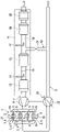
- FIG. 1 shows a simplified representation of an internal combustion engine for a motor vehicle that is suitable for carrying out a method according to the invention.
- the cylinders 2 each delimit a combustion chamber 4 with reciprocating pistons 3 guided therein and a cylinder head.
- the fresh gas is at least partly air that is sucked in from the environment and is then passed through a fresh gas compressor 22 .
- This fresh gas compressor 22 is part of an exhaust gas turbocharger, which also includes an exhaust gas turbine 6, which is integrated into an exhaust line 7 of the internal combustion engine.
- Exhaust gas that is produced during the combustion of mixture quantities consisting of the fresh gas and fuel injected directly into the combustion chambers 4 via fuel injectors (not shown) is discharged via the exhaust system 7 of the internal combustion engine.
- the exhaust gas also flows through an exhaust gas after-treatment device 11, which is provided for removing components of the exhaust gas that are regarded as pollutants from the exhaust gas and/or converting them into harmless components.
- each of the combustion chambers 4 is assigned two intake valves 8 and two exhaust valves 9, which can be actuated via a valve actuating device 10, which can include, for example, a camshaft (not shown) for the intake valves 8 on the one hand and the exhaust valves 9 on the other , be pressed.
- a valve actuating device 10 can include, for example, a camshaft (not shown) for the intake valves 8 on the one hand and the exhaust valves 9 on the other , be pressed.
- the reciprocating pistons 3 guided by a crankshaft 21 to which the reciprocating pistons 3 are connected via connecting rods (not shown), are moved in the combustion chambers 4 in an oscillating manner between a top dead center (TDC) and a bottom dead center (UT).
- TDC top dead center
- UT bottom dead center
- the reciprocating piston 3 alternately a gas exchange stroke cycle and a Perform power stroke cycle.
- the gas exchange stroke cycle includes an exhaust stroke movement of the respective piston 3 (corresponding to an exhaust stroke in the associated combustion chamber 4) and an intake stroke movement (corresponding to an intake stroke in the associated combustion chamber 4).
- the power stroke cycle includes a compression stroke movement of the respective reciprocating piston 3 (corresponding to a compression stroke in the associated combustion chamber 4) and a power stroke movement (corresponding to a power stroke in the associated combustion chamber 4).
- the four stroke movements of the reciprocating pistons 3 or the four corresponding cycles of the cyclic processes taking place in the combustion chambers 4 correspond to an operating cycle that takes place in the respective combustion chamber 4 of the internal combustion engine 1 .
- the intake valves 8 and the exhaust valves 9 are opened and closed by means of the valve actuating device 10 at defined control times, and thereby fresh gas is introduced into the combustion chambers 4 in a controlled manner or exhaust gas is discharged from them.
- the exhaust gas turbine 6 comprises a device for variable turbine inflow (not shown) that can be controlled by means of a control device (not shown).
- VTG variable turbine inflow
- this can comprise a plurality of guide vanes (not shown) arranged in an inlet of the exhaust gas turbine 6, which are designed to be individually rotatable, these being adjustable together by means of an adjusting device (not shown).
- guide vanes not shown
- they narrow the free flow cross section in the inlet of the exhaust gas turbine 6 to a greater or lesser extent and also influence the section of the primary inflow of the turbine impeller and the orientation of this inflow.
- the exhaust gas aftertreatment device 11 of the internal combustion engine comprises, seen in the flow direction of the exhaust gas, a first exhaust gas aftertreatment component 12, which can be a nitrogen oxide storage catalytic converter or a combination of an oxidation catalytic converter and a nitrogen oxide storage catalytic converter.
- This first exhaust gas aftertreatment component 12 is followed by a second exhaust gas aftertreatment component in the form of a particle filter 13 .
- the particle filter 13 or the filter body forming it has a catalytically active coating, as a result of which the particle filter 13 simultaneously represents a first SCR catalytic converter of the exhaust gas aftertreatment device 11 .
- the for the catalytic reduction of pollutants contained in the exhaust gas, in particular nitrogen oxides, required presence of reducing agent in the exhaust gas, which flows through the particle filter 13 acting as the first SCR catalytic converter, is implemented by means of a first metering device 14 for such a reducing agent, which is arranged upstream of the particle filter 13.
- the reducing agent can in particular be ammonia or an ammonia-containing solution.
- a first mixing device 15 is arranged between the first dosing device 14 and the particle filter 13, which can be designed, for example, in the form of flow guide elements that cause turbulence in the flow of the exhaust gas already mixed with the reducing agent.
- the exhaust gas aftertreatment device 11 comprises, in an arrangement downstream of the particle filter 13, a (further) SCR catalytic converter 16 as a third exhaust gas aftertreatment component.
- the SCR catalytic converter 16 is in an arrangement upstream of it a second dosing device 17 for a reducing agent and, in an arrangement between this second one Metering device 17 and the SCR catalyst 16, a second mixing device 18 assigned.
- the second dosing device 17 is provided because between the particle filter 13 and this second dosing device 17, an LP exhaust gas recirculation line 19 branches off from the exhaust line 7, via which at least part of the exhaust gas is recirculated to the fresh gas line 5, controlled by an EGR valve 24 as required can be.
- the LP exhaust gas recirculation line 19 opens into a section of the fresh gas line 5 which is located upstream of the fresh gas compressor 22 . If such a LP exhaust gas recirculation is carried out, it should be avoided that the exhaust gas recirculated in this way contains unreacted reducing agent. Dosing by means of the first dosing device 14 should therefore take place at least when LP exhaust gas recirculation is being carried out in such a way that the exhaust gas downstream of the particle filter 13 contains as little reducing agent as possible. However, this then requires an additional introduction of reducing agent into the exhaust gas in front of the SCR catalytic converter 16 in order to be able to achieve a reduction of nitrogen oxides by this.
- a blocking catalytic converter 20 is provided as the last component in the flow direction or as the fourth exhaust gas aftertreatment component of the exhaust gas aftertreatment device 11 .
- This is an oxidation catalytic converter that converts reducing agents (particularly ammonia to form N 2 and H 2 O) that have not been converted in the SCR catalytic converter 16 so that this reducing agent is prevented from being released into the environment.
- fuel is injected both via a main injection which takes place during the respective compression strokes in the combustion chambers 4 is carried out, and is introduced into the combustion chambers 4 via a post-injection, which is carried out during the respective power strokes.
- the main injection takes place relatively late during the warm-up phase of the internal combustion engine, which means that a relatively large proportion of the chemically bound energy in this fuel is converted into thermal energy of the exhaust gas and not into drive power of the internal combustion engine 1 .
- the fuel introduced via the post-injections which contributes only to a small extent to the generation of drive power of the internal combustion engine 1 and thus mainly causes relatively high exhaust gas temperatures. Since this obviously has a negative effect on the efficiency during operation of the internal combustion engine 1, the invention provides for this post-injection of fuel to be carried out exclusively during the warm-up phase, but not during normal operation of the internal combustion engine.
- the type of introduction of the fuel into the combustion chambers 4 provided according to the invention produces relatively hot exhaust gas, which contributes to the fastest possible heating of the exhaust gas aftertreatment device 11 when it subsequently flows through the exhaust line 7 .
- the invention also provides for the VTG 23 to be set during the warm-up phase in such a way that the compression of the fresh gas by means of the fresh gas compressor 22 is at a corresponding operating point of the internal combustion engine compared to normal operation 1 is greater.
- the compression output of the fresh-gas compressor 22 is maximized permanently during the warm-up phase, insofar as this is permitted by the operation of the internal combustion engine 1 and in particular the drive power required by it.
- exhaust gas is fed back into the combustion chambers 4 of the internal combustion engine 1 via the LP exhaust gas recirculation line 19 and thus as part of the fresh gas.
- the raw emissions of nitrogen oxides from the internal combustion engine 1 can be kept low.
- this achieves a relatively large exhaust gas mass flow, via which a correspondingly large amount of heat energy is made available for heating up the exhaust gas aftertreatment device 11 .
- VTG 23 The relatively extensive and in particular maximum closing of the VTG 23 should therefore provide the greatest possible oxygen supply - reduced by a reasonable proportion recirculated exhaust gas - can be realized in the combustion chambers so that more fuel (taking into account defined (lambda) limits with regard to the combustion air ratio) can be injected to increase the exhaust gas temperature.
Landscapes
- Engineering & Computer Science (AREA)
- Chemical & Material Sciences (AREA)
- Combustion & Propulsion (AREA)
- Mechanical Engineering (AREA)
- General Engineering & Computer Science (AREA)
- Exhaust-Gas Circulating Devices (AREA)
- Supercharger (AREA)
Abstract
Description
- Die Erfindung betrifft ein Verfahren zum Betreiben einer Brennkraftmaschine mit einem Verbrennungsmotor während einer Warmlaufphase, die sich insbesondere an einen Kaltstart des Verbrennungsmotors anschließen kann.
- Um möglichst geringe Schadstoffemissionen einer Brennkraftmaschine zu realisieren, sollten die in einen Abgasstrang der Brennkraftmaschine integrierten Abgasnachbehandlungskomponenten einer Abgasnachbehandlungseinrichtung, die insbesondere einen oder mehrere Katalysatoren sowie einen Partikelfilter umfassen kann, möglichst stets Betriebstemperaturen aufweisen, die oberhalb der jeweiligen Anspringtemperaturen (auch "Light-off-Temperatur genannt) liegen, ab denen von einer ausreichenden Wirksamkeit hinsichtlich der jeweils vorgesehenen Abgasnachbehandlung ausgegangen werden kann. Nach einem Kaltstart der Brennkraftmaschine, bei dem nicht nur der Verbrennungsmotor sondern auch die Abgasnachbehandlungskomponenten Betriebstemperaturen aufweisen, die deutlich unterhalb der jeweiligen Anspringtemperatur liegen, sollten die Betriebstemperaturen zumindest einiger der Abgasnachbehandlungskomponenten möglichst schnell die jeweilige Anspringtemperatur erreichen. Um dies zu gewährleisten, ist es bekannt, einzelne Abgasnachbehandlungskomponenten aktiv zu beheizen, was zum einen mittels hierfür vorgesehener Heizvorrichtungen, die beispielsweise elektrische Heizelemente umfassen oder als Brenner ausgebildet sein können, möglich ist. Weiterhin können sogenannte innermotorische Maßnahmen umgesetzt werden, die darauf abzielen, durch einen gezielten Betrieb des Verbrennungsmotors mit einem relativ schlechten Wirkungsgrad relativ heißes Abgas zu erzeugen, so dass über das Abgas eine relativ schnelle Erwärmung der Abgasnachbehandlungskomponenten erreicht werden kann.
- Die
DE 10 2018 124 869 A1 offenbart ein Verfahren zur Abgasnachbehandlung eines Verbrennungsmotors mit mindestens einem Brennraum. Der Verbrennungsmotor ist über seinen Einlass mit einem Luftversorgungssystem und über seinen Auslass mit einer Abgasanlage des Verbrennungsmotors verbunden. In der Abgasanlage ist mindestens eine Abgasnachbehandlungskomponente zur Konvertierung von Schadstoffen im Abgas des Verbrennungsmotors angeordnet. Vorgesehen ist, dass der Lastzustand des Verbrennungsmotors sowie die streckenbezogenen Emissionen, insbesondere die streckenbezogenen NOx-Emissionen ermittelt werden. Nähern sich die streckenbezogenen Emissionen einem definierten Schwellenwert an und ist abzusehen, dass bei unveränderten Motorparametern diese streckenbezogenen Emissionen nicht erfüllt werden können, wird die Leistung und/oder das Drehmoment des Verbrennungsmotors reduziert, um die Rohemissionen des Verbrennungsmotors zu verringern. - Die
DE 10 2018 220 121 A1 beschreibt ein Abgasnachbehandlungssystem für einen Verbrennungsmotor, der eine Abgasanlage mit einem Abgaskanal umfasst, wobei in dem Abgaskanal ein Oxidationskatalysator, anschließend ein Dosierelement zur Eindosierung eines Reduktionsmittels und daran anschließend eine Abgasnachbehandlungskomponente zur selektiven, katalytischen Reduktion von Stickoxiden angeordnet sind. Vorgesehen ist, dass der Oxidationskatalysator ein elektrisches Heizelement aufweist, über welches ein Abschnitt des Oxidationskatalysators beheizbar ist. Nach einem Kaltstart wird der Oxidationskatalysator auf seine Anspringtemperatur aufgeheizt und anschließend das weitere Aufheizen durch innermotorische Maßnahmen und eine exotherme Umsetzung von unverbrannten Abgaskomponenten auf dem Oxidationskatalysator unterstützt. - Die
DE 10 2017 123 492 A1 offenbart ein Abgasnachbehandlungssystem für einen Verbrennungsmotor. Das Abgasnachbehandlungssystem weist einen Abgaskanal auf, in dem eine Abgasturbine eines Abgasturboladers, daran anschließend ein erster Katalysator, insbesondere ein Oxidationskatalysator, und dann ein zweiter Katalysator, insbesondere ein SCR-Katalysator oder ein Partikelfilter mit einer SCR-Beschichtung, angeordnet sind. Vorgesehen ist, dass ein Bypasskanal den Abgaskanal stromaufwärts der Abgasturbine mit dem Abgaskanal stromabwärts des ersten Katalysators und stromaufwärts des zweiten Katalysators verbindet, wobei in dem Bypasskanal ein dritter Katalysator, insbesondere ein Oxidationskatalysator, angeordnet ist. Bei einem Schwachlastbetrieb des Verbrennungsmotors wird ein Bypassventil des Bypasskanals geöffnet und dadurch ein Abgasstrom an der Abgasturbine und an dem ersten Katalysator vorbei geleitet sowie durch den in dem Bypasskanal befindlichen dritten Katalysator gereinigt. - Der Erfindung lag die Aufgabe zugrunde, in einer Warmlaufphase im Betrieb einer Brennkraftmaschine möglichst geringe Schadstoffemissionen zu realisieren.
- Diese Aufgabe ist bei der Durchführung eines Verfahrens gemäß dem Patentanspruch 1 gelöst. Vorteilhafte Ausführungsformen dieses Verfahrens sind Gegenstände der weiteren Patentansprüche und ergeben sich aus der nachfolgenden Beschreibung der Erfindung.
- Erfindungsgemäß ist ein Verfahren zum Betreiben einer Brennkraftmaschine vorgesehen, wobei die Brennkraftmaschine zumindest einen Verbrennungsmotor, insbesondere einen selbstzündenden Verbrennungsmotor, einen Frischgastrang und einen Abgasstrang umfasst. In den Abgasstrang sind zumindest eine Abgasturbine mit variabler Turbinengeometrie (VTG), die Teil eines Abgasturboladers ist, und eine Abgasnachbehandlungseinrichtung integriert. Die Abgasnachbehandlungseinrichtung oder zumindest einzelne Abgasnachbehandlungskomponenten davon können vorzugsweise stromab (bezüglich der Strömungsrichtung von Abgas durch den Abgasstrang ausgehend von dem Verbrennungsmotor) der Abgasturbine angeordnet sein. In den Frischgasstrang ist zumindest ein Frischgasverdichter der Abgasturbine integriert. Weiterhin ist eine ND-Abgasrückführleitung vorgesehen, die stromab der Abgasturbine und vorzugsweise auch stromab der Abgasnachbehandlungseinrichtung oder zumindest stromab einiger der Abgasnachbehandlungskomponenten davon aus dem Abgasstrang abzweigt und die stromauf (bezüglich der Strömungsrichtung von Frischgas durch den Frischgasstrang in Richtung des Verbrennungsmotors) des Frischgasverdichters in den Frischgasstrang mündet.
- Das erfindungsgemäße Verfahren ist dadurch gekennzeichnet, dass während einer Warmlaufphase, die insbesondere mit einem Kaltstart der Brennkraftmaschine beginnen kann, (zumindest temporär und/oder gleichzeitig)
- die VTG derart eingestellt wird, dass die Verdichtung des Frischgases mittels des Frischgasverdichters im Vergleich zu einem Normalbetrieb in einem entsprechenden Betriebspunkt (d.h. bei gleicher Betriebslast und Betriebsdrehzahl) größer und insbesondere maximiert ist, woraus eine maximale Brennraumfüllung resultieren kann, und
- eine (direkte) Nacheinspritzung von Kraftstoff in zumindest einen Brennraum des Verbrennungsmotors (zumindest auch) während eines Expansionstakts in diesem Brennraum durchgeführt wird und
- Abgas über die ND-Abgasrückführleitung geführt wird.
- Ein Einbringen von Kraftstoff ist erfindungsgemäß dann eine Nacheinspritzung, wenn diese zusätzlich und vorzugsweise auch zeitlich beabstandet zu einer zuvor erfolgten Haupteinspritzung erfolgt.
- Vorzugsweise kann vorgesehen sein, dass die die Nacheinspritzung in einem Bereich des Drehwinkels (Kurbelwellenwinkel) einer Abtriebswelle des vorzugsweise als Viertakt-Hubkolbenmotor ausgebildeten Verbrennungsmotors, der zwischen 10°KW und 180°KW nach dem oberen OT in einem Arbeitshubzyklus liegt, stattfindet.
- Sofern der Verbrennungsmotor eine Mehrzahl von Brennräumen aufweist, kann die Nacheinspritzung von Kraftstoff in einen, mehrere oder, vorzugsweise, in alle Brennräume erfolgen.
- Zur Realisierung einer "variablen Turbinengeometrie (VTG)" umfasst eine Abgasturbine eine Vorrichtung, mittels der ein Strömungsquerschnitt, über den Abgas zu einem, Turbinenlaufrad der Abgasturbine geführt werden kann, zumindest hinsichtlich der Wirksamkeit veränderbar ist, wozu insbesondere die Größe des freien Strömungsquerschnitts und/oder der Winkel der Anströmung von Schaufeln des Turbinenlaufrads veränderbar sein kann.
- Als "Warmlaufphase" gilt erfindungsgemäß ein Betrieb der Brennkraftmaschine, bei dem zumindest eine Abgasnachbehandlungskomponente der Abgasnachbehandlungseinrichtung eine Betriebstemperatur aufweist, die unter der dazugehörigen Anspringtemperatur liegt. Als "Kaltstart" gilt erfindungsgemäß eine Inbetriebnahme der Brennkraftmaschine, bei der zumindest eine Abgasnachbehandlungskomponente der Abgasnachbehandlungseinrichtung eine Betriebstemperatur aufweist, die ungefähr (d.h. auch mit einer Abweichung von bis zu 10%, 20% oder 30%) der Umgebungstemperatur entspricht. Eine Warmlaufphase muss sich dabei nicht immer an einen Kaltstart oder an eine Inbetriebnahme der Brennkraftmaschine mit einer unterhalb einer dazugehörigen Anspringtemperatur liegenden Betriebstemperatur zumindest einer Abgasnachbehandlungskomponente anschließen; vielmehr kann eine Warmlaufphase auch damit beginnen, dass die Brennkraftmaschine und insbesondere der Verbrennungsmotor davon zuvor derart betrieben wurde, dass die zuvor bereits überschrittene Anspringtemperatur wieder (für einen definierten Mindestzeitraum) unterschritten wird, wie dies gegebenenfalls bei einem länger andauernden Leerlauf- oder Schubbetrieb des Verbrennungsmotors der Fall sein kann.
- Die Erfindung zielt darauf ab, durch den Kraftstoff, der über die Nacheinspritzung in den zumindest einen Brennraum eingebracht wird, gezielt eine Erhöhung der Temperatur des von dem Verbrennungsmotor erzeugten Abgases zu erreichen. Dieses relativ heiße Abgas kann dann dazu genutzt werden, die Abgasnachbehandlungseinrichtung möglichst schnell aufzuheizen. Durch die relativ spät erfolgende Nacheinspritzung kann erreicht werden, dass dieser Kraftstoff, der noch in dem entsprechenden Brennraum umgesetzt wird, nur noch zu einem geringen Anteil zur Erzeugung von Antriebsleistung des Verbrennungsmotors beiträgt, so dass relativ viel der in dem Kraftstoff gebundenen chemischen Energie als Wärmeenergie des Abgases von dem Verbrennungsmotor abgeführt und damit in den Abgasstrang eingeleitet wird.
- Diese zusätzliche Wärmeenergie steht demnach für ein Aufheizen der Abgasnachbehandlungseinrichtung zur Verfügung.
- Die erfindungsgemäß weiterhin vorgesehen Vergrößerung und insbesondere Maximierung der Verdichtung des Frischgases mittels einer entsprechenden Einstellung der VTG sorgt dafür, dass dem Verbrennungsmotor ausreichend Sauerstoff für eine Umsetzung auch des über die Nacheinspritzung eingebrachten Kraftstoffs zur Verfügung steht.
- Die erfindungsgemäß weiterhin vorgesehene Rückführung von Abgas über die ND-Abgasrückführleitung sorgt einerseits dafür, dass die bei den Verbrennungen auftretenden Spitzentemperaturen relativ gering bleiben, was sich vorteilhaft auf die Stickoxidrohemissionen des Verbrennungsmotors auswirkt. Hinzu kommt, dass über die Abgasrückführung eine zusätzliche, inerte Gasmasse in den zumindest einen Brennraum eingebracht und damit auch als Teil des Abgases wieder von dem Verbrennungsmotor abgeführt wird, so dass insgesamt ein relativ großer Abgasmassen- bzw. Enthalpiestrom realisiert werden kann, der sich vorteilhaft hinsichtlich der angestrebten Aufheizung der Abgasnachbehandlungseinrichtung auswirkt.
- Um zu gewährleisten, dass ein möglichst großer Abgasmassenstrom über die Abgasnachbehandlungseinrichtung und auch über die Abgasturbine geführt wird, kann vorzugsweise vorgesehen sein, dass die Brennkraftmaschine entweder keine HD-Abgasrückführleitung, die stromauf der Abgasturbine aus dem Abgasstrang abzweigt und stromab des Frischgasverdichters in den Frischgasstrang mündet, aufweist oder dass dann, wenn die Brennkraftmaschine eine solche HD-Abgasrückführleitung aufweist, bei dem Betrieb der Brennkraftmaschine während der Warmlaufphase kein oder nur relativ wenig Abgas im Vergleich zu dem Normalbetrieb in dem entsprechenden Betriebspunkt über die HD-Abgasrückführleitung geführt wird. Dadurch kann sichergestellt werden, dass möglichst viel Wärmeenergie von dem Abgas auf die Abgasnachbehandlungseinrichtung übertragen werden kann und zudem, dass möglichst viel Abgasenthalpie zur Verfügung steht, um über die Abgasturbine eine möglichst große Verdichtungsleistung des Frischgasverdichters realisieren.
- Erfindungsgemäß kann weiterhin bevorzugt vorgesehen sein, dass eine Haupteinspritzung von Kraftstoff in zumindest einen/den Brennraum des Verbrennungsmotors (zumindest auch) während eines Verdichtungstakts in diesem Brennraum verspätet im Vergleich zu dem Normalbetrieb durchgeführt wird. Dadurch soll auch der über die Haupteinspritzung eingebrachte Kraftstoff gezielt so umgesetzt werden, dass ein relativ großer Anteil der darin chemisch gebundenen Energie nicht in Antriebsleistung des Verbrennungsmotors sondern in Wärmeenergie des Abgases gewandelt wird.
- Um zu vermeiden, dass die erfindungsgemäß vorgesehene Erhöhung der Temperatur des Abgases, die insbesondere durch die späte Nacheinspritzung von Kraftstoff bewirkt wird, zu überhöhten Schadstoffrohemissionen des Verbrennungsmotors führt, kann vorzugsweise vorgesehen sein, dass ein Einstellen der Kraftstoffmengen, die bei den Nacheinspritzungen in den zumindest einen Brennraum eingebracht werden, in Abhängigkeit von dem Verbrennungsluftverhältnis, mit dem der Verbrennungsmotor betrieben wird, durchgeführt wird. Dabei kann insbesondere vorgesehen sein, dass die Kraftstoffmengen derart eingestellt werden, dass ein Verbrennungsluftverhältnis (λ) von zwischen 0,98 und 1,02 oder von zwischen 1,1 und 1,2 erreicht wird. Ein Verbrennungsluftverhältnis von zwischen 0,98 und 1,02 kann dabei insbesondere dann vorgesehen sein, wenn ein Fokus auf einem Geringhalten der Stickoxidrohemissionen (NOx) liegt, während durch ein Verbrennungsluftverhältnis von zwischen 1,1 und 1,2 insbesondere die Rohemissionen von Kohlenmonoxid (CO), unverbrannten Kohlenwasserstoffen (HC) und (Ruß-)Partikeln gering gehalten werden können.
- Der Sauerstoffgehalt des Abgases kann dabei vorteilhafterweise mittels eines geeigneten Abgassensors, beispielsweise mittels eines konventionellen NOx-Sensors oder einer Lambdasonde, der in den Abgasstrang integriert sein kann, gemessen werden. Alternativ oder ergänzend ist aber auch eine beispielsweise modellbasierte, rechnerische Ermittlung des Verbrennungsluftverhältnisses möglich, d.h. dieser wird aus den Betriebsparametern der Brennkraftmaschine, insbesondere den eingespritzen Kraftstoffmengen, der Betriebsdrehzahl, dem Ladedruck, etc., berechnet.
- Die Einstellung des Verbrennungsluftverhältnisses kann insbesondere geregelt erfolgen, wobei dann in dem entsprechenden Regelkreis der Sollwert des Verbrennungsluftverhältnisses die Führungsgröße, der Istwert des Verbrennungsluftverhältnisses die Regelgröße und die Kraftstoffmenge, die über die Nacheinspritzung in den Brennraum eingebracht wird, die Stellgröße ist.
- Bei dem Verbrennungsmotor einer erfindungsgemäßen Brennkraftmaschine kann es sich insbesondere um einen (selbstzündenden und qualitätsgeregelten) Dieselmotor handeln. Es besteht aber auch die Möglichkeit, dass es sich bei dem Verbrennungsmotor um einen (fremdgezündeten und quantitätsgeregelten) Ottomotor oder um eine Kombination aus selbstzündendem und fremdgezündeten Verbrennungsmotor, z.B. um einen Verbrennungsmotor mit homogener Kompressionszündung, handelt. Der Verbrennungsmotor kann dabei sowohl mit Flüssigkraftstoff (d.h. Diesel oder Benzin) als auch mit einem gasförmigen Kraftstoff (insbesondere Erdgas, LNG oder LPG) betrieben werden.
- Eine erfindungsgemäß betriebene Brennkraftmaschine kann insbesondere zur (direkten oder indirekten) Bereitstellung der Fahrantriebsleistung für ein Kraftfahrzeug vorgesehen sein. Das Kraftfahrzeug kann dabei insbesondere ein radbasiertes und nicht schienengebundenes Kraftfahrzeug (vorzugsweise ein PKW oder ein LKW) sein.
- Die Erfindung wird nachfolgend anhand eines in der Zeichnung dargestellten Ausführungsbeispiels näher erläutert. Darin zeigt die
- Fig. 1
- eine für die Durchführung eines erfindungsgemäßen Verfahrens geeignete Brennkraftmaschine in vereinfachter Darstellung.
- Die Fig. 1 zeigt in vereinfachter Darstellung eine für die Durchführung eines erfindungsgemäßen Verfahrens geeignete Brennkraftmaschine für ein Kraftfahrzeug.
- Diese umfasst einen (Viertakt-)Verbrennungsmotor 1, der beispielhaft in Form eines Hubkolbenmotors mit vier in Reihe angeordneten Zylindern 2 ausgestaltet ist. Die Zylinder 2 begrenzen mit darin geführten Hubkolben 3 und einem Zylinderkopf jeweils einen Brennraum 4. Diesen Brennräumen 4 wird im Betrieb des Verbrennungsmotors 1 und damit der Brennkraftmaschine Frischgas über einen Frischgasstrang 5 zugeführt. Bei dem Frischgas handelt es sich zumindest teilweise um Luft, die aus der Umgebung angesaugt wird und die anschließend über einen Frischgasverdichter 22 geführt wird. Dieser Frischgasverdichter 22 ist Teil eines Abgasturboladers, der weiterhin eine Abgasturbine 6 umfasst, die in einen Abgasstrang 7 der Brennkraftmaschine integriert ist. Abgas, das bei der Verbrennung von Gemischmengen entstanden ist, die aus dem Frischgas sowie aus direkt über Kraftstoffinjektoren (nicht dargestellt) in die Brennräume 4 eingespritztem Kraftstoff bestehen, wird über den Abgasstrang 7 der Brennkraftmaschine abgeführt. Das Abgas durchströmt dabei neben der Abgasturbine 6 auch eine Abgasnachbehandlungseinrichtung 11, die dafür vorgesehen ist, Bestandteile des Abgases, die als Schadstoffe angesehen werden, aus dem Abgas zu entfernen und/oder in unschädliche Bestandteile umzuwandeln.
- Jedem der Brennräume 4 sind gemäß dem in der Fig. 1 dargestellten Ausgestaltungsbeispiel zwei Einlassventile 8 und zwei Auslassventile 9 zugeordnet, die über eine Ventilbetätigungsvorrichtung 10, die beispielsweise jeweils eine Nockenwelle (nicht dargestellten) für einerseits die Einlassventile 8 und andererseits die Auslassventile 9 umfassen kann, betätigt werden.
- Im Betrieb des Verbrennungsmotors 1 werden die Hubkolben 3, geführt von einer Kurbelwelle 21, mit der die Hubkolben 3 über Pleuel (nicht dargestellt) verbunden sind, in den Brennräumen 4 oszillierend zwischen einem oberen Totpunkt (OT) und einem unteren Totpunkt (UT) bewegt, wobei die Hubkolben 3 abwechselnd einen Ladungswechselhubzyklus und einen Arbeitshubzyklus durchführen. Der Ladungswechselhubzyklus umfasst eine Ausstoßhubbewegung des jeweiligen Hubkolbens 3 (entsprechend einem Ausstoßtakt in dem dazugehörigen Brennraum 4) sowie eine Ansaughubbewegung (entsprechend einem Ansaugtakt in dem dazugehörigen Brennraum 4). Der Arbeitshubzyklus umfasst eine Verdichtungshubbewegung des jeweiligen Hubkolbens 3 (entsprechend einem Verdichtungstakt in dem dazugehörigen Brennraum 4) und eine Arbeitshubbewegung (entsprechend einem Arbeitstakt in dem dazugehörigen Brennraum 4). Die vier Hubbewegungen der Hubkolben 3 beziehungsweise die vier entsprechenden Takte der in den Brennräumen 4 ablaufenden Kreisprozesse entsprechen dabei einem Betriebszyklus, der in dem jeweiligen Brennraum 4 des Verbrennungsmotors 1 stattfindet.
- In Abhängigkeit von dem Drehwinkel der Kurbelwelle 21 während der Ladungswechselhubzyklen der einzelnen Hubkolben 3 werden die Einlassventile 8 und die Auslassventile 9 mittels der Ventilbetätigungsvorrichtung 10 zu definierten Steuerzeiten geöffnet und geschlossen und dadurch gesteuert Frischgas in die Brennräume 4 eingebracht oder Abgas aus diesen abgeführt.
- Um in einem Betrieb des Verbrennungsmotors 1 mit unterschiedlichen Betriebslasten und unterschiedlichen Betriebsdrehzahlen eine möglichst optimale Nutzung der Enthalpie des Abgases zur Erzeugung von Verdichtungsleistung mittels des Abgasturboladers realisieren zu können, umfasst die Abgasturbine 6 eine mittels einer Steuerungsvorrichtung (nicht dargestellt) ansteuerbare Vorrichtung zur variablen Turbinenanströmung (VTG) 23. Diese kann in bekannter Weise eine Mehrzahl von in einem Einlass der Abgasturbine 6 angeordnete Leitschaufeln (nicht dargestellt) umfassen, die individuell drehbar ausgebildet sind, wobei diese gemeinsame mittels einer Verstellvorrichtung (nicht dargestellt) verstellbar sind. In Abhängigkeit von den Drehstellungen der Leitschaufeln verengen diese den freien Strömungsquerschnitt in dem Einlass der Abgasturbine 6 mehr oder weniger und beeinflussen zudem den Abschnitt der primären Anströmung des Turbinenlaufrads und die Ausrichtung dieser Anströmung.
- Die Abgasnachbehandlungseinrichtung 11 der Brennkraftmaschine umfasst in Strömungsrichtung des Abgases gesehen eine erste Abgasnachbehandlungskomponente 12, bei der es sich um einen Stickoxidspeicherkatalysator oder um eine Kombination aus einem Oxidationskatalysator und einem Stickoxidspeicherkatalysator handeln kann.
- Dieser ersten Abgasnachbehandlungskomponente 12 schließt sich eine zweite Abgasnachbehandlungskomponente in Form eines Partikelfilters 13 an. Dabei ist beispielhaft vorgesehen, dass der Partikelfilter 13 beziehungsweise der diesen ausbildende Filterkörper eine katalytisch wirksame Beschichtung aufweist, wodurch der Partikelfilter 13 gleichzeitig einen ersten SCR-Katalysator der Abgasnachbehandlungseinrichtung 11 darstellt. Die für die katalytische Reduktion von in dem Abgas enthaltenen Schadstoffen, insbesondere Stickoxiden, erforderliche Anwesenheit von Reduktionsmittel in dem Abgas, das den als erster SCR-Katalysator wirksamen Partikelfilter 13 durchströmt, wird mittels einer stromauf des Partikelfilters 13 angeordneten ersten Dosiervorrichtung 14 für ein solches Reduktionsmittel realisiert. Bei dem Reduktionsmittel kann es sich insbesondere um Ammoniak oder um eine ammoniakhaltige Lösung handeln. Zwischen der ersten Dosiervorrichtung 14 und dem Partikelfilter 13 ist eine erste Mischvorrichtung 15 angeordnet, die beispielsweise in Form von Strömungsleitelementen, die Verwirbelungen in der Strömung des bereits mit dem Reduktionsmittel vermischten Abgases bewirken, ausgebildet sein kann.
- Die Abgasnachbehandlungseinrichtung 11 umfasst, in einer Anordnung stromab des Partikelfilters 13, als dritte Abgasnachbehandlungskomponente einen (weiteren) SCR-Katalysator 16. Dem SCR Katalysator 16 ist in einer Anordnung stromauf davon eine zweite Dosiervorrichtung 17 für ein Reduktionsmittel sowie, in einer Anordnung zwischen dieser zweiten Dosiervorrichtung 17 und dem SCR-Katalysator 16, eine zweite Mischvorrichtung 18 zugeordnet. Die zweite Dosiervorrichtung 17 ist vorgesehen, weil zwischen dem Partikelfilter 13 und dieser zweiten Dosiervorrichtung 17 eine ND-Abgasrückführleitung 19 aus dem Abgasstrang 7 abzweigt, über die bedarfsweise, gesteuert mittels eines AGR-Ventils 24, zumindest ein Teil des Abgases in den Frischgasstrang 5 zurückgeführt werden kann. Die ND-Abgasrückführleitung 19 mündet dazu in einen Abschnitt des Frischgasstrangs 5, der stromauf des Frischgasverdichters 22 gelegen ist. Sofern eine solche ND-Abgasrückführung durchgeführt wird, sollte vermieden werden, dass in dem dabei zurückgeführten Abgas noch nicht umgesetztes Reduktionsmittel enthalten ist. Eine Dosierung mittels der ersten Dosiervorrichtung 14 sollte daher zumindest dann, wenn eine ND-Abgasrückführung durchgeführt wird, derart erfolgen, dass stromab des Partikelfilters 13 möglichst kein Reduktionsmittel mehr in dem Abgas enthalten ist. Dies erfordert dann jedoch ein zusätzliches Einbringen von Reduktionsmittel in das Abgas vor dem SCR-Katalysator 16, um durch diesen eine Reduktion von Stickoxiden realisieren zu können.
- Als in Strömungsrichtung letzte Komponente beziehungsweise als vierte Abgasnachbehandlungskomponente der Abgasnachbehandlungseinrichtung 11 ist ein Sperrkatalysator 20 vorgesehen. Hierbei handelt es sich um einen Oxidationskatalysator, der Reduktionsmittel umsetzt (insbesondere Ammoniak zu N2 und H2O), das in dem SCR-Katalysator 16 nicht umgesetzt wurde, so dass ein Freisetzen dieses Reduktionsmittels in die Umgebung vermieden wird.
- Erfindungsgemäß ist vorgesehen, dass während einer Warmlaufphase, die sich insbesondere an einen Kaltstart der Brennkraftmaschine anschließen kann, Kraftstoff sowohl über eine Haupteinspritzung, die während der jeweiligen Verdichtungstakte in den Brennräumen 4 durchgeführt wird, als auch über eine Nacheinspritzung, die während der jeweiligen Arbeitstakte durchgeführt wird, in die Brennräume 4 eingebracht wird. Im Vergleich zu einem Normalbetrieb der Brennkraftmaschine, der immer oder zumindest meistens dann vorgesehen ist, wenn die Betriebstemperaturen zumindest einiger und insbesondere aller der Abgasnachbehandlungskomponenten oberhalb der jeweiligen Anspringtemperatur liegen, erfolgt die Haupteinspritzung während der Warmlaufphase der Brennkraftmaschine relativ spät, wodurch ein relativ großer Anteil der in diesem Kraftstoff chemisch gebundenen Energie zu Wärmeenergie des Abgases und nicht zu Antriebsleistung des Verbrennungsmotors 1 umgewandelt wird. Dasselbe gilt für den über die Nacheinspritzungen eingebrachten Kraftstoff, der nur zu einem geringen Teil zur Erzeugung von Antriebsleistung des Verbrennungsmotors 1 beiträgt und somit hauptsächlich relativ hohe Abgastemperaturen bewirkt. Da sich dies offensichtlich negativ auf den Wirkungsgrad im Betrieb des Verbrennungsmotors 1 auswirkt, ist erfindungsgemäß vorgesehen, diese Nacheinspritzung von Kraftstoff ausschließlich während der Warmlaufphase, nicht jedoch während eines Normalbetriebs der Brennkraftmaschine durchzuführen.
- Durch die erfindungsgemäß vorgesehene Art der Einbringung des Kraftstoffs in die Brennräume 4 wird relativ heißes Abgas erzeugt, das bei der anschließenden Durchströmung des Abgasstrangs 7 zu einem möglichst schnellen Aufheizen der Abgasnachbehandlungseinrichtung 11 beiträgt.
- Um dem Verbrennungsmotor 1 ausreichend viel Sauerstoff für eine Umsetzung des gesamten zugeführten Kraftstoffs zuzuführen, ist erfindungsgemäß weiterhin vorgesehen, die VTG 23 während der Warmlaufphase derart einzustellen, dass die Verdichtung des Frischgases mittels des Frischgasverdichters 22 im Vergleich zu dem Normalbetrieb in einem entsprechenden Betriebspunkt des Verbrennungsmotors 1 größer ist. Insbesondere ist vorgesehen, die Verdichtungsleistung des Frischgasverdichters 22 dauerhaft während der Warmlaufphase zu maximieren, soweit dies der Betrieb des Verbrennungsmotors 1 und insbesondere die von diesem angeforderte Antriebsleistung zulässt.
- Zudem wird während der Warmlaufphase Abgas über die ND-Abgasrückführleitung 19 und damit als Teil des Frischgases in die Brennräume 4 des Verbrennungsmotors 1 zurück geführt. Dadurch können zum einen die Stickoxidrohemissionen des Verbrennungsmotors 1 gering gehalten werden. Zum anderen wird dadurch ein relativ großer Abgasmassenstrom erreicht, über den entsprechend viel Wärmeenergie für ein Aufheizen der Abgasnachbehandlungseinrichtung 11 zur Verfügung gestellt wird.
- Durch das relativ weitgehende und insbesondere maximale Schließen der VTG 23 soll demnach ein möglichst großes Sauerstoffangebot - reduziert um einen sinnvollen Anteil an zurückgeführtem Abgas - in den Brennräumen realisiert werden, damit mehr Kraftstoff (unter Berücksichtigung von definierten (Lambda-)Grenzen bezüglich des Verbrennungsluftverhältnisses) zur Steigerung der Abgastemperatur eingespritzt werden kann.
-
- 1
- (Viertakt-)Verbrennungsmotor
- 2
- Zylinder
- 3
- Hubkolben
- 4
- Brennraum
- 5
- Frischgasstrang
- 6
- Abgasturbine
- 7
- Abgasstrang
- 8
- Einlassventil
- 9
- Auslassventil
- 10
- Ventilbetätigungsvorrichtung
- 11
- Abgasnachbehandlungseinrichtung
- 12
- erste Abgasnachbehandlungskomponente
- 13
- Partikelfilter
- 14
- erste Dosiervorrichtung für ein Reduktionsmittel
- 15
- erste Mischvorrichtung
- 16
- SCR-Katalysator
- 17
- zweite Dosiervorrichtung für ein Reduktionsmittel
- 18
- zweite Mischvorrichtung
- 19
- ND-Abgasrückführleitung
- 20
- Sperrkatalysator
- 21
- Kurbelwelle
- 22
- Frischgasverdichter
- 23
- Vorrichtung zur variablen Turbinenanströmung (VTG)
- 24
- AGR-Ventil
Claims (7)
- Verfahren zum Betreiben einer Brennkraftmaschine mit einem Verbrennungsmotor (1), einem Frischgastrang (5) und einem Abgasstrang (7), wobei in den Abgasstrang (7) eine Abgasturbine (6) mit variabler Turbinengeometrie (23) eines Abgasturbolader und eine Abgasnachbehandlungseinrichtung (11) integriert sind und in den Frischgasstrang (5) ein Frischgasverdichter (22) des Abgasturboladers integriert ist und wobei eine ND-Abgasrückführleitung (19) stromab der Abgasturbine (6) aus dem Abgasstrang (7) abzweigt und stromauf des Frischgasverdichters (22) in den Frischgasstrang (5) mündet, dadurch gekennzeichnet, dass während einer Warmlaufphase- die variable Turbinengeometrie (23) derart eingestellt wird, dass die Verdichtung des Frischgases mittels des Frischgasverdichters (22) im Vergleich zu einem Normalbetrieb in einem entsprechenden Betriebspunkt größer ist und- Abgas über die ND-Abgasrückführleitung (19) geführt wird und- eine Nacheinspritzung von Kraftstoff in zumindest einen Brennraum (4) des Verbrennungsmotors (1) während eines Arbeitstakts in diesem Brennraum (4) durchgeführt wird.
- Verfahren gemäß Anspruch 1, dadurch gekennzeichnet, dass der Verbrennungsmotor (1) selbstzündend ausgestaltet ist.
- Verfahren gemäß Anspruch 1 oder 2, dadurch gekennzeichnet, dass die Brennkraftmaschine keine HD-Abgasrückführleitung, die stromauf der Abgasturbine (6) aus dem Abgasstrang (7) abzweigt und stromab des Frischgasverdichters (22) in den Frischgasstrang (5) mündet, aufweist oder dass die Brennkraftmaschine eine solche HD-Abgasrückführleitung aufweist, wobei dann kein oder relativ wenig Abgas im Vergleich zu dem Normalbetrieb in dem entsprechenden Betriebspunkt über die HD-Abgasrückführleitung geführt wird.
- Verfahren gemäß einem der vorhergehenden Ansprüche, dadurch gekennzeichnet, dass eine Haupteinspritzung von Kraftstoff in zumindest einen/den Brennraum (4) des Verbrennungsmotors (1) während eines Verdichtungstakts in diesem Brennraum (4) verspätet im Vergleich zu dem Normalbetrieb durchgeführt wird.
- Verfahren gemäß einem der vorhergehenden Ansprüche, dadurch gekennzeichnet, dass eine Einstellung der Kraftstoffmengen, die bei den Nacheinspritzungen in den zumindest einen Brennraum (4) eingebracht werden, in Abhängigkeit von dem Verbrennungsluftverhältnis, mit dem der Verbrennungsmotor betrieben wird, durchgeführt wird.
- Verfahren gemäß Anspruch 5, dadurch gekennzeichnet, dass das Verbrennungsluftverhältnis durch eine Messung des Sauerstoffgehalts des Abgases mittels eines Abgassensors ermittelt wird.
- Verfahren gemäß Anspruch 5 oder 6, dadurch gekennzeichnet, dass die Kraftstoffmengen derart eingestellt werden, dass das Verbrennungsluftverhältnis von zwischen 0,98 und 1,02 oder von zwischen 1,1 und 1,2 beträgt.
Applications Claiming Priority (1)
| Application Number | Priority Date | Filing Date | Title |
|---|---|---|---|
| DE102021107952.7A DE102021107952A1 (de) | 2021-03-30 | 2021-03-30 | Aufheizen einer Abgasnachbehandlungseinrichtung während eines Warmlaufbetriebs einer Brennkraftmaschine |
Publications (1)
| Publication Number | Publication Date |
|---|---|
| EP4067638A1 true EP4067638A1 (de) | 2022-10-05 |
Family
ID=80928719
Family Applications (1)
| Application Number | Title | Priority Date | Filing Date |
|---|---|---|---|
| EP22163275.5A Pending EP4067638A1 (de) | 2021-03-30 | 2022-03-21 | Aufheizen einer abgasnachbehandlungseinrichtung während eines warmlaufbetriebs einer brennkraftmaschine |
Country Status (2)
| Country | Link |
|---|---|
| EP (1) | EP4067638A1 (de) |
| DE (1) | DE102021107952A1 (de) |
Citations (10)
| Publication number | Priority date | Publication date | Assignee | Title |
|---|---|---|---|---|
| EP0454943A1 (de) * | 1990-05-04 | 1991-11-06 | Dr.Ing.h.c. F. Porsche Aktiengesellschaft | Turbolader an einer Brennkraftmaschine |
| EP1574691A2 (de) * | 2004-03-10 | 2005-09-14 | Toyota Jidosha Kabushiki Kaisha | Vorrichtung und Verfahren zur Steuerung eines Benzinmotors mit einem Turbokompressor mit verstellbaren Leitschaufeln |
| US20070089400A1 (en) * | 2005-10-21 | 2007-04-26 | Yiqun Huang | Fast warm-up of diesel aftertreatment system during cold start |
| US20110139136A1 (en) * | 2009-09-30 | 2011-06-16 | Linsong Guo | Techniques for enhancing aftertreatment regeneration capability |
| US20130332051A1 (en) * | 2012-06-12 | 2013-12-12 | Caterpillar Inc. | Compression Ignition Engine With Low Load Rapid Warm Up Strategy |
| US20170314486A1 (en) * | 2016-04-27 | 2017-11-02 | GM Global Technology Operations LLC | Control of engine exhaust backpressure following engine cold-start |
| DE102017123492A1 (de) | 2017-10-10 | 2019-04-11 | Volkswagen Aktiengesellschaft | Abgasnachbehandlungssystem und Verfahren zur Abgasnachbehandlung eines Verbrennungsmotors |
| DE102018124869A1 (de) | 2018-10-09 | 2020-04-09 | Volkswagen Aktiengesellschaft | Verfahren zum Betreiben eines Verbrennungsmotors sowie Verbrennungsmotor |
| DE102018220121A1 (de) | 2018-11-23 | 2020-05-28 | Volkswagen Aktiengesellschaft | Abgasnachbehandlungssystem und Verfahren zur Abgasnachbehandlung eines Verbrennungsmotors |
| US20200224614A1 (en) * | 2019-01-16 | 2020-07-16 | Ford Global Technologies, Llc | Method and system for emissions reduction |
-
2021
- 2021-03-30 DE DE102021107952.7A patent/DE102021107952A1/de active Pending
-
2022
- 2022-03-21 EP EP22163275.5A patent/EP4067638A1/de active Pending
Patent Citations (10)
| Publication number | Priority date | Publication date | Assignee | Title |
|---|---|---|---|---|
| EP0454943A1 (de) * | 1990-05-04 | 1991-11-06 | Dr.Ing.h.c. F. Porsche Aktiengesellschaft | Turbolader an einer Brennkraftmaschine |
| EP1574691A2 (de) * | 2004-03-10 | 2005-09-14 | Toyota Jidosha Kabushiki Kaisha | Vorrichtung und Verfahren zur Steuerung eines Benzinmotors mit einem Turbokompressor mit verstellbaren Leitschaufeln |
| US20070089400A1 (en) * | 2005-10-21 | 2007-04-26 | Yiqun Huang | Fast warm-up of diesel aftertreatment system during cold start |
| US20110139136A1 (en) * | 2009-09-30 | 2011-06-16 | Linsong Guo | Techniques for enhancing aftertreatment regeneration capability |
| US20130332051A1 (en) * | 2012-06-12 | 2013-12-12 | Caterpillar Inc. | Compression Ignition Engine With Low Load Rapid Warm Up Strategy |
| US20170314486A1 (en) * | 2016-04-27 | 2017-11-02 | GM Global Technology Operations LLC | Control of engine exhaust backpressure following engine cold-start |
| DE102017123492A1 (de) | 2017-10-10 | 2019-04-11 | Volkswagen Aktiengesellschaft | Abgasnachbehandlungssystem und Verfahren zur Abgasnachbehandlung eines Verbrennungsmotors |
| DE102018124869A1 (de) | 2018-10-09 | 2020-04-09 | Volkswagen Aktiengesellschaft | Verfahren zum Betreiben eines Verbrennungsmotors sowie Verbrennungsmotor |
| DE102018220121A1 (de) | 2018-11-23 | 2020-05-28 | Volkswagen Aktiengesellschaft | Abgasnachbehandlungssystem und Verfahren zur Abgasnachbehandlung eines Verbrennungsmotors |
| US20200224614A1 (en) * | 2019-01-16 | 2020-07-16 | Ford Global Technologies, Llc | Method and system for emissions reduction |
Also Published As
| Publication number | Publication date |
|---|---|
| DE102021107952A1 (de) | 2022-10-06 |
Similar Documents
| Publication | Publication Date | Title |
|---|---|---|
| EP2628922B1 (de) | Verfahren zum Betreiben einer selbstzündenden Brennkraftmaschine | |
| DE102010063425A1 (de) | Verfahren und Systeme zur Steuerung von Emissionssystemen | |
| DE102010063871A1 (de) | Verfahren und Systeme für die Emissionssystemsteuerung | |
| EP3344863B1 (de) | Verfahren sowie vorrichtung zur abgasnachbehandlung einer brennkraftmaschine | |
| WO1999022128A1 (de) | Verfahren zur abgasnachbehandlung bei kolbenbrennkraftmaschinen mit kraftstoff-direkteinspritzung | |
| DE112010000892T5 (de) | Abgasreinigung mit Ammoniakerzeugung an Bord | |
| DE102021111152A1 (de) | Motoranordnung und Verfahren | |
| EP0527362B2 (de) | Verfahren und Vorrichtung zur Verminderung des Stickoxidausstosses von Verbrennungsmotoren | |
| DE10203025A1 (de) | Vorrichtung und Verfahren zur Steuerung eines Verbrennungsmotors | |
| DE102021205170A1 (de) | Brennkraftmaschine mit einer stromab eines Frischgasverdichters abzweigenden Sekundärluftleitung | |
| EP4067638A1 (de) | Aufheizen einer abgasnachbehandlungseinrichtung während eines warmlaufbetriebs einer brennkraftmaschine | |
| WO2020193594A1 (de) | Verfahren zum betreiben eines verbrennungsmotors sowie verbrennungsmotor | |
| DE102018130799A1 (de) | Verbrennungsmotor und Verfahren zum Betreiben eines Verbrennungsmotors | |
| DE102019113736A1 (de) | Brennkraftmaschine mit variabler Auslassventilbetätigung und mit elektrischer Heizvorrichtung im Abgasstrang | |
| DE102022121068A1 (de) | Abgasregelung für Motoren mit magerer Verbrennung | |
| DE102020133225A1 (de) | Nachbehandlungssystem und -Verfahren | |
| DE102009051028A1 (de) | Antriebsaggregat sowie Verfahren zum Betreiben eines Antriebsaggregats | |
| EP4083399B1 (de) | Brennkraftmaschine mit elektrischer abgasturbine und abgasnachbehandlungseinrichtung stromauf der abgasturbine | |
| DE102015204505A1 (de) | Verfahren zum Betreiben einer fremdgezündeten, direkteinspritzenden Brennkraftmaschine sowie fremdgezündete, direkteinspritzende Brennkraftmaschine | |
| DE102019113730B4 (de) | Brennkraftmaschine mit variabler Auslassventilbetätigung und mit mindestens zwei SCR-Katalysatoren | |
| DE102021102240A1 (de) | Abgasnachbehandlung bei einer Brennkraftmaschine | |
| DE102023202560B4 (de) | Verfahren zum Betreiben eines Dieselmotors sowie Dieselmotor | |
| DE102019113741A1 (de) | Brennkraftmaschine mit variabler Auslassventilbetätigung und mit elektromotorischer oder mechanischer Aufladung | |
| EP3683427A1 (de) | Abgasnachbehandlung eines verbrennungsmotors | |
| DE102019113735A1 (de) | Verfahren zum Betreiben einer Brennkraftmaschine mit variabler und temperaturgeregelter Auslassventilbetätigung |
Legal Events
| Date | Code | Title | Description |
|---|---|---|---|
| PUAI | Public reference made under article 153(3) epc to a published international application that has entered the european phase |
Free format text: ORIGINAL CODE: 0009012 |
|
| STAA | Information on the status of an ep patent application or granted ep patent |
Free format text: STATUS: THE APPLICATION HAS BEEN PUBLISHED |
|
| AK | Designated contracting states |
Kind code of ref document: A1 Designated state(s): AL AT BE BG CH CY CZ DE DK EE ES FI FR GB GR HR HU IE IS IT LI LT LU LV MC MK MT NL NO PL PT RO RS SE SI SK SM TR |
|
| STAA | Information on the status of an ep patent application or granted ep patent |
Free format text: STATUS: REQUEST FOR EXAMINATION WAS MADE |
|
| 17P | Request for examination filed |
Effective date: 20230405 |
|
| RBV | Designated contracting states (corrected) |
Designated state(s): AL AT BE BG CH CY CZ DE DK EE ES FI FR GB GR HR HU IE IS IT LI LT LU LV MC MK MT NL NO PL PT RO RS SE SI SK SM TR |
|
| STAA | Information on the status of an ep patent application or granted ep patent |
Free format text: STATUS: EXAMINATION IS IN PROGRESS |
|
| 17Q | First examination report despatched |
Effective date: 20240919 |