EP4067584A1 - Method for shutting off water and a water outlet device - Google Patents
Method for shutting off water and a water outlet device Download PDFInfo
- Publication number
- EP4067584A1 EP4067584A1 EP22166583.9A EP22166583A EP4067584A1 EP 4067584 A1 EP4067584 A1 EP 4067584A1 EP 22166583 A EP22166583 A EP 22166583A EP 4067584 A1 EP4067584 A1 EP 4067584A1
- Authority
- EP
- European Patent Office
- Prior art keywords
- chamber
- water outlet
- water
- variable
- shut
- Prior art date
- Legal status (The legal status is an assumption and is not a legal conclusion. Google has not performed a legal analysis and makes no representation as to the accuracy of the status listed.)
- Pending
Links
Images


Classifications
-
- E—FIXED CONSTRUCTIONS
- E03—WATER SUPPLY; SEWERAGE
- E03C—DOMESTIC PLUMBING INSTALLATIONS FOR FRESH WATER OR WASTE WATER; SINKS
- E03C1/00—Domestic plumbing installations for fresh water or waste water; Sinks
- E03C1/02—Plumbing installations for fresh water
- E03C1/04—Water-basin installations specially adapted to wash-basins or baths
- E03C1/0408—Water installations especially for showers
-
- B—PERFORMING OPERATIONS; TRANSPORTING
- B05—SPRAYING OR ATOMISING IN GENERAL; APPLYING FLUENT MATERIALS TO SURFACES, IN GENERAL
- B05B—SPRAYING APPARATUS; ATOMISING APPARATUS; NOZZLES
- B05B1/00—Nozzles, spray heads or other outlets, with or without auxiliary devices such as valves, heating means
- B05B1/14—Nozzles, spray heads or other outlets, with or without auxiliary devices such as valves, heating means with multiple outlet openings; with strainers in or outside the outlet opening
- B05B1/18—Roses; Shower heads
- B05B1/185—Roses; Shower heads characterised by their outlet element; Mounting arrangements therefor
-
- B—PERFORMING OPERATIONS; TRANSPORTING
- B05—SPRAYING OR ATOMISING IN GENERAL; APPLYING FLUENT MATERIALS TO SURFACES, IN GENERAL
- B05B—SPRAYING APPARATUS; ATOMISING APPARATUS; NOZZLES
- B05B1/00—Nozzles, spray heads or other outlets, with or without auxiliary devices such as valves, heating means
- B05B1/14—Nozzles, spray heads or other outlets, with or without auxiliary devices such as valves, heating means with multiple outlet openings; with strainers in or outside the outlet opening
- B05B1/18—Roses; Shower heads
-
- B—PERFORMING OPERATIONS; TRANSPORTING
- B05—SPRAYING OR ATOMISING IN GENERAL; APPLYING FLUENT MATERIALS TO SURFACES, IN GENERAL
- B05B—SPRAYING APPARATUS; ATOMISING APPARATUS; NOZZLES
- B05B1/00—Nozzles, spray heads or other outlets, with or without auxiliary devices such as valves, heating means
- B05B1/28—Nozzles, spray heads or other outlets, with or without auxiliary devices such as valves, heating means with integral means for shielding the discharged liquid or other fluent material, e.g. to limit area of spray; with integral means for catching drips or collecting surplus liquid or other fluent material
-
- B—PERFORMING OPERATIONS; TRANSPORTING
- B05—SPRAYING OR ATOMISING IN GENERAL; APPLYING FLUENT MATERIALS TO SURFACES, IN GENERAL
- B05B—SPRAYING APPARATUS; ATOMISING APPARATUS; NOZZLES
- B05B1/00—Nozzles, spray heads or other outlets, with or without auxiliary devices such as valves, heating means
- B05B1/30—Nozzles, spray heads or other outlets, with or without auxiliary devices such as valves, heating means designed to control volume of flow, e.g. with adjustable passages
-
- B—PERFORMING OPERATIONS; TRANSPORTING
- B05—SPRAYING OR ATOMISING IN GENERAL; APPLYING FLUENT MATERIALS TO SURFACES, IN GENERAL
- B05B—SPRAYING APPARATUS; ATOMISING APPARATUS; NOZZLES
- B05B15/00—Details of spraying plant or spraying apparatus not otherwise provided for; Accessories
- B05B15/60—Arrangements for mounting, supporting or holding spraying apparatus
- B05B15/65—Mounting arrangements for fluid connection of the spraying apparatus or its outlets to flow conduits
- B05B15/652—Mounting arrangements for fluid connection of the spraying apparatus or its outlets to flow conduits whereby the jet can be oriented
- B05B15/654—Mounting arrangements for fluid connection of the spraying apparatus or its outlets to flow conduits whereby the jet can be oriented using universal joints
-
- E—FIXED CONSTRUCTIONS
- E03—WATER SUPPLY; SEWERAGE
- E03C—DOMESTIC PLUMBING INSTALLATIONS FOR FRESH WATER OR WASTE WATER; SINKS
- E03C1/00—Domestic plumbing installations for fresh water or waste water; Sinks
- E03C1/02—Plumbing installations for fresh water
- E03C1/04—Water-basin installations specially adapted to wash-basins or baths
- E03C1/0404—Constructional or functional features of the spout
-
- F—MECHANICAL ENGINEERING; LIGHTING; HEATING; WEAPONS; BLASTING
- F16—ENGINEERING ELEMENTS AND UNITS; GENERAL MEASURES FOR PRODUCING AND MAINTAINING EFFECTIVE FUNCTIONING OF MACHINES OR INSTALLATIONS; THERMAL INSULATION IN GENERAL
- F16K—VALVES; TAPS; COCKS; ACTUATING-FLOATS; DEVICES FOR VENTING OR AERATING
- F16K21/00—Fluid-delivery valves, e.g. self-closing valves
- F16K21/04—Self-closing valves, i.e. closing automatically after operation
-
- E—FIXED CONSTRUCTIONS
- E03—WATER SUPPLY; SEWERAGE
- E03C—DOMESTIC PLUMBING INSTALLATIONS FOR FRESH WATER OR WASTE WATER; SINKS
- E03C1/00—Domestic plumbing installations for fresh water or waste water; Sinks
- E03C1/02—Plumbing installations for fresh water
- E03C2001/026—Plumbing installations for fresh water with flow restricting devices
Definitions
- the present disclosure relates to a household product, and in particular relates to a water outlet device.
- Some showers in the existing techniques are disposed with a movable plate that can move upward and downward in a chamber and seal a water outlet hole in a body.
- a pressure chamber is formed between the movable plate and a water outlet panel.
- the movable plate As the movable plate has a certain weight, the water needs to be held under pressure in the pressure chamber for a period of time, from the water being turned on for the shower until the water actually flows from the shower, to form sufficient buoyancy to lift up the movable plate, so the shower has problems of high starting water pressure and outflow delay.
- a main technical problem of present disclosure to be resolved is to provide a method for shutting off water, a sensitivity is high, and a delay is low.
- a main technical problem of present disclosure to be resolved is to provide another method for shutting off water, and quick stopping of shutting off of water is achieved at any angle.
- the present disclosure provides a method for shutting off water that is applied to a water outlet device, which comprises enabling a volume of a variable chamber to increase to form a negative pressure chamber to suck residual water in a water outlet chamber into the negative pressure chamber by releasing negative pressure at a connection of the variable chamber and the water outlet chamber when the water is shut off.
- variable chamber In a preferred embodiment, which comprises enabling the volume of the variable chamber to decrease by generating the negative pressure at the connection of the variable chamber and the water outlet chamber when the water is turned on.
- the present disclosure provides a method for shutting off water that is applied to a water outlet device, which comprises enabling a water shut-off sealing member to hermetically seal a connection of a water outlet hole and a water outlet chamber by a volume of air in the water outlet chamber of the water outlet device increasing to generate negative pressure when the water is shut off.
- a volume of a variable chamber to increase to form a negative pressure chamber to suck residual water in the water outlet chamber into the negative pressure chamber by releasing the negative pressure at a connection of the variable chamber and the water outlet chamber when the water is shut off.
- a volume of a variable chamber to decrease by generating the negative pressure at a connection of a variable chamber and the water outlet chamber when the water is turned on.
- the present disclosure provides a water outlet device, which comprises a variable chamber and a water outlet chamber that are disposed in the water outlet device, and the variable chamber is in communication with the water outlet chamber; the variable chamber is independently disposed outside of the water outlet chamber.
- Volumes of the variable chamber are not equal when water is turned on and when the water is shut off to enable the variable chamber to generate a negative pressure chamber when the water is shut off.
- variable chamber is in communication with the water outlet chamber through a through hole
- the water outlet chamber comprises a flow passage having variable cross-sectional areas, after the water is accelerated through the flow passage having the variable cross-sectional areas, the negative pressure is generated at the through hole.
- a piston is disposed in the water outlet device, and the piston is hermetically sealed to an inner wall of the water outlet device to form the variable chamber; and the piston is connected to a spring, when the volume of the variable chamber decreases, the spring is squeezed by the piston to accumulate an elastic restoring force.
- variable chamber is an elastic chamber made of elastic material, and when the volume of the variable chamber decreases, the elastic material contracts to generate an elastic restoring force.
- the present disclosure discloses a water outlet device, which comprises a variable chamber and a water outlet chamber that are disposed in the water outlet device, the variable chamber is in communication with the water outlet chamber, and the variable chamber is independently disposed outside of the water outlet chamber.
- a flow passage having variable cross-sectional areas comprises a through hole in communication with the variable chamber, and the water outlet chamber comprises the flow passage having the variable cross-sectional areas for accelerating flowing-through water to generate a negative pressure at the through hole.
- the negative pressure when the water is turned on, the negative pressure is generated at the through hole, and a volume of the variable chamber decreases; and when the water is shut off, the negative pressure disappears at the through hole, and the volume of the variable chamber increases to form a negative pressure chamber.
- a piston is disposed in the water outlet device, and the piston is hermetically sealed to an inner wall of the water outlet device to form the variable chamber; and the piston is connected to a spring, when a volume of the variable chamber decreases, the spring is squeezed by the piston to accumulate an elastic restoring force.
- variable chamber is an elastic chamber made of elastic material, when a volume of the variable chamber decreases, the elastic material contracts to generate an elastic restoring force.
- the present disclosure discloses a water outlet device, which comprises a variable chamber and a water outlet chamber that are disposed in the water outlet device, and the variable chamber is in communication with the water outlet chamber;
- a Venturi structure is disposed in the water outlet device for generating negative pressure at a connection of the variable chamber and the water outlet chamber when water is turned on.
- the Venturi structure comprises a through hole for the connection of the variable chamber and the water outlet chamber and a flow passage having variable cross-sectional areas disposed in the water outlet chamber.
- the negative pressure when the water is turned on, the negative pressure is generated at the through hole, and a volume of the variable chamber decreases; and when the water is shut off, the negative pressure disappears at the through hole, and the volume of the variable chamber increases to form a negative pressure chamber.
- a piston is disposed in the water outlet device, and the piston is hermetically sealed to an inner wall of the water outlet device to form the variable chamber; and the piston is connected to a spring, when a volume of the variable chamber decreases, the spring is squeezed by the piston to accumulate an elastic restoring force.
- variable chamber is an elastic chamber made of elastic material, when a volume of the variable chamber decreases, the elastic material contracts to generate elastic restoring force.
- a water outlet device which comprises a variable chamber and a water outlet chamber that are disposed in the water outlet device and a water shut-off sealing member that is disposed at a connection of a water outlet hole and the water outlet chamber.
- the water shut-off sealing member is a one-way sheet having a cut opening.
- variable chamber is independently disposed outside of the water outlet chamber, and the variable chamber is in communication with the water outlet chamber through a through hole.
- the water outlet chamber comprises a flow passage having variable cross-section areas, after the water is accelerated through the flow passage having the variable cross-sectional areas, the negative pressure is generated at the through hole.
- a piston is disposed in the water outlet device, and the piston is hermetically sealed to an inner wall of the water outlet device to form the variable chamber; and the piston is connected to a spring, when a volume of the variable chamber decreases, the spring is squeezed by the piston to accumulate an elastic restoring force.
- variable chamber is an elastic chamber made of elastic material, when a volume of the variable chamber decreases, the elastic material contracts to generate an elastic restoring force.
- the present disclosure discloses a water outlet device, which comprises a variable chamber and a water outlet chamber that are disposed in the water outlet device and a water shut-off sealing member that is disposed at a connection of a water outlet hole and the water outlet chamber; and the variable chamber is independently arranged outside of the water outlet chamber.
- Volumes of the variable chamber are not equal when water is turned on and when the water is shut off to enable the variable chamber to form a negative pressure chamber when the water is shut off.
- the water shut-off sealing member is a one-way sheet with a cut opening.
- variable chamber is in communication with the water outlet chamber through a through hole.
- the water outlet chamber comprises a flow passage having variable cross-section areas, after the water is accelerated through the flow passage having the variable cross-sectional areas, the negative pressure is generated at the through hole.
- a piston is disposed in the water outlet device, and the piston is hermetically sealed to an inner wall of the water outlet device to form the variable chamber; and the piston is connected to a spring, when the volume of the variable chamber decreases, the spring is squeezed by the piston to accumulate an elastic restoring force.
- variable chamber is an elastic chamber made of elastic material, when the volume of the variable chamber decreases, the elastic material contracts to generate an elastic restoring force.
- the present disclosure discloses a water outlet device, which comprises a variable chamber and a water outlet chamber that are disposed in the water outlet device and a water shut-off sealing member that is disposed at a connection of a water outlet hole and the water outlet chamber.
- a Venturi structure is disposed in the water outlet device for generating negative pressure at a connection of the variable chamber and the water outlet chamber when water is turned on.
- the water shut-off sealing member is a one-way sheet with a cut opening.
- the Venturi structure comprises a through hole for a connection of the variable chamber and the water outlet chamber and a flow passage having variable cross-sectional areas disposed in the water outlet chamber.
- a negative pressure is generated at the through hole, and a volume of the variable chamber decreases.
- the negative pressure disappears at the through hole, and the volume of the variable chamber increases to form a negative pressure chamber.
- a piston is disposed in the water outlet device, and the piston is hermetically sealed to an inner wall of the water outlet device to form the variable chamber; and the piston is connected to a spring, when a volume of the variable chamber decreases, the spring is squeezed by the piston to accumulate an elastic restoring force.
- variable chamber is an elastic chamber made of elastic material, when a volume of the variable chamber decreases, the elastic material contracts to generate an elastic restoring force.
- the present disclosure provides a method for shutting off water and a water outlet device.
- the water When water is turned on, the water is accelerated through a flow passage having a decreased cross-sectional area.
- pressure energy can be reduced, so negative pressure is generated on the flow passage having the variable cross-sectional area.
- a through hole on the flow passage having the variable cross-sectional area is connected to the variable chamber, so that air in the variable chamber is sucked away to enable the piston move inward against an elastic force of a spring under an action of external atmospheric air pressure.
- variable chamber is independently disposed outside of the water outlet chamber, a decreasing of the volume of the variable chamber does not depend on water pressure acting on the variable chamber when the water is turned on. In this way, even in case the water pressure is relatively low when the water is turned on, the water can also be output smoothly.
- the present disclosure further provides a method for shutting off water and a water outlet device.
- a water shut-off sealing member disposed at a connection of the water outlet hole and the water outlet chamber is added based on the above-mentioned method.
- the above-mentioned method for shutting off water and the water outlet device have very high sensitivity. Water output can be realized as soon as the water is turned on, and the water can be stopped as soon as the water is shut off, and a starting water pressure is further relatively low.
- the terms “upper”, “lower”, “inner”, “outer”, “top/bottom”, etc. indicate an orientation or a positional relationship based on the orientation shown in the drawings.
- the positional relationship is only for convenience for describing the present disclosure and simplifying the description, rather than indicating or implying that the pointed device or the pointed element must have a specific orientation or be constructed and operated in the specific orientation, and therefore should not be understood as a limitation of the present disclosure.
- the terms “first” and “second” are only used for descriptive purposes and should not be understood as indicating or implying relative importance.
- connection can be a wall-mounted connection, a detachable connection, or an integral connection, a mechanical connection, an electrical connection, a direct connection, an indirect connection through an intermediate medium, and a connection between two components.
- connection can be a wall-mounted connection, a detachable connection, or an integral connection, a mechanical connection, an electrical connection, a direct connection, an indirect connection through an intermediate medium, and a connection between two components.
- This embodiment provides a method for shutting off water, which is applied to a water outlet device.
- the method comprises a step that when water is shut off, negative pressure is released at a connection of a variable chamber 1 and a water outlet chamber 2, so that a volume of the variable chamber 1 increases to form a negative pressure chamber to suck residual water in the water outlet chamber 2 into the negative pressure chamber.
- the residual water in the water outlet chamber 2 can be directly sucked into the negative pressure chamber to form quick stopping effects of shutting off of water by this step.
- out-flowing water from the water outlet device can be shut off immediately such that the water is shut off without waiting for buoyancy of the water in the pressure chamber decreasing, just like the existing techniques. In this way, sensitivity is relatively high.
- this embodiment further comprises a step that the volume of the variable chamber 1 of the water outlet device decreases when the water is turned on. In this way, the volume of the variable chamber 1 is relatively small when the water is turned on, which provides a basis for increasing the volume when the water is shut off.
- variable chamber 1 In order to achieve the volume of the variable chamber 1 changing, when the water is turned on, a negative pressure is generated at the connection of the variable chamber 1 and the water outlet chamber 2. Air in the variable chamber 1 enters into the water outlet chamber 2, and the volume of the variable chamber 1 decreases. When the water is shut off, the negative pressure disappears at the connection of the variable chamber 1 and the water outlet chamber 2, the variable chamber 1 can expand due to an elastic restoring force, and the volume of the variable chamber 1 increases. Further, as the variable chamber 1 is independently disposed outside of the water outlet chamber 2, the decreasing of the volume of the variable chamber 1 does not depend on water pressure acting on the variable chamber 1 when the water is turned on. Therefore, even in case that the water pressure is relatively low when the water is turned on, the water can flow out smoothly.
- the aforementioned technical solution is suitably applied to a state in which the water outlet device is maintained horizontal. Therefore, in this state, after the water is shut off, everywhere in the water outlet chamber 2 is filled with water, and the water in the water outlet chamber 2 can be only sucked into the variable chamber 1 by the negative pressure. Once the water outlet device is inclined, the residual water in the water outlet chamber 2 will flow to an inclined side, causing a part of the water outlet chamber 2 to be in communication with external atmospheric air pressure. At this time, the water outlet chamber 2 cannot generate the negative pressure, and the residual water cannot be maintained in the water outlet chamber 2. Therefore, the residual water will still drip from a water outlet hole, and the quick stopping effects of the shutting off of water cannot be achieved.
- this embodiment further provides a method for shutting off water, which is applied to the water outlet device.
- the method comprises a step that when the water is shut off, a volume of air in the water outlet chamber 2 of the water outlet device increases to generate a negative pressure, so that a water shut-off sealing member 4 at the water outlet hole 3 is hermetically sealed with the connection of the water outlet chamber 2 and the water outlet hole 3.
- water with low pressure can be turned on using this method.
- a pressure of out-flowing water in the water outlet chamber 2 is applied to the water shut-off sealing member 4 to push the water shut-off sealing member 4 to move downward, so that the connection of the water outlet hole 3 and the water outlet chamber 2 is reset. Therefore, the water pressure required is relatively low using this turn-on method, and rapidly turning on water can be achieved under a low pressure.
- this embodiment provides two applicable structures. It should be noted that this embodiment uses a top spray shower as an example. However, a structure of this part can be also applied to other water outlet devices, which is a simple replacement of this embodiment and will not be repeatedly described herewith.
- this embodiment provides a water outlet device, which comprises a variable chamber 1 and a water outlet chamber 2 that are disposed in the water outlet device.
- the variable chamber 1 is in communication with the water outlet chamber 2.
- the variable chamber 1 is independently disposed outside of the water outlet chamber 2.
- the variable chamber 1 being independently disposed outside of the water outlet chamber 2 means that when water flows through the water outlet chamber 2, the water will not enter into the variable chamber 1 from a connection of the variable chamber 1 and the water outlet chamber 2.
- the variable chamber 1 can be disposed on an outer periphery of the water outlet chamber 2, and a center line of the variable chamber 1 can be perpendicular to a water flow direction. Or, the center line of the variable chamber 1 and the water flow direction can form an angle.
- the variable chamber 1 being independently disposed outside of the water flow direction of the water outlet chamber 2 means that when the water flows through the water outlet chamber 2, the water will not enter into the variable chamber 1 from the connection of the variable chamber 1 and the water outlet chamber 2.
- the water outlet chamber 2 comprises a flow passage 5 having variable cross-sectional areas for accelerating the flowing-through water.
- the variable chamber 1 is disposed on an outer periphery of the flow passage 5 having variable cross sections, and the flow passage 5 having the variable cross-sectional areas comprises a through hole 6 in communication with the variable chamber 1.
- the through hole comprises a first opening 61 disposed on the variable chamber 1 and a second opening 62 disposed on the flow passage 5 having the variable cross sections.
- the first opening 61 is in communication with the second opening 62 through the water outlet chamber 2.
- the second opening 62 disposed on the flow passage 5 having the variable cross-sectional areas is in communication with the first opening 61 of the variable chamber 1 to enable air in the variable chamber 1 to be sucked away, so that the variable chamber 1 contracts and a volume of the variable chamber 1 decreases due to the external atmospheric air pressure.
- the negative pressure at the second opening 62 disappears (which restores to a state of approximately atmospheric air pressure), and the volume of the variable chamber 1 increases. In this way, the volume of the variable chamber 1 changes following with a change between a water turn-on state and a water shut-off state, so that the variable chamber 1 forms a negative pressure chamber when the water is shut off.
- a piston 7 is disposed in the water outlet device, and the piston 7 is hermetically sealed to an inner wall of the water outlet device to form the variable chamber 1.
- a side of the piston 7 facing a fixed end of the variable chamber is connected to a spring 8.
- the spring 8 is squeezed by the piston 7 to accumulate an elastic restoring force.
- the piston 7 moves in a direction along which the volume of the variable chamber 1 increases under a combined action of the elastic restoring force and the atmospheric air pressure, so that the volume of the variable chamber 1 increases to form a negative pressure chamber and the residual water in the water outlet chamber 2 is sucked into the variable chamber 1 through the first opening 61 and the second opening 62.
- the water When the water is turned on each time hereafter, the water is accelerated through the flow passage having decreased cross-sectional areas.
- the kinetic energy increases, the pressure energy decreases, therefore, the negative pressure is generated at the flow passage 5 having the variable cross-sectional areas, and the second opening 62 of the flow passage 5 having variable cross-sectional areas is in communication with the first opening 61 of the variable chamber 1, so that the air in the variable chamber 1 and the water sucked into the variable chamber 1 when the water is shut off in a previous time is sucked into the water outlet chamber 2.
- a movement direction of the piston is perpendicular to the water flow direction in the water outlet chamber 2.
- the piston 7 is connected to the inner wall of the water outlet device through two Y-shaped sealing rings 9 and 10.
- the two Y-shaped sealing rings 9 and 10 are disposed in opposite directions, so that one Y-shaped sealing ring 9 is used to hermetically seal and isolate the external atmosphere air from the variable chamber 1, and the other Y-shaped sealing ring 10 is used to hermetically seal the residual water sucked into the variable chamber 1 when the water is shut off, so as to prevent the residual water from flowing out from this position.
- a water shut-off sealing member 4 is disposed on a connection of the water outlet hole 3 and the water outlet chamber 2.
- the water shut-off sealing member 4 is a one-way sheet having a cut opening.
- the residual water in the water outlet chamber 2 is sucked into the variable chamber 1, so that the volume of the air in the water outlet chamber 2 increases to generate the negative pressure.
- the external atmospheric air pressure acts on the one-way sheet having the cut opening, so that the one-way sheet is upwardly arched to achieve the quick stopping effects of the shutting off of water.
- the water received in the water outlet hole 3 is backwardly sucked due to the one-way sheet upwardly arching, so that there is no residual water on a surface of the water outlet hole 3.
- this embodiment differs from Embodiment 1 in that the variable chamber 1 is an elastic chamber made of an elastic material.
- the elastic material contracts to generate an elastic restoring force.
- the elastic material is selected from elastic silicone. The rest is the same as Embodiment 1 and will not be repeatedly described herewith.
- the invention may be summarized as follows:
- a method for shutting off water that is applied to a water outlet device which comprises enabling a volume of a variable chamber to increase to form a negative pressure chamber to suck residual water in a water outlet chamber into the negative pressure chamber by releasing negative pressure at a connection of the variable chamber and the water outlet chamber when the water is shut off.
- a method for shutting off water that is applied to a water outlet device which comprises enabling a water shut-off sealing member to hermetically seal a connection of a water outlet hole and a water outlet chamber by a volume of air in the water outlet chamber of the water outlet device increasing to generate negative pressure when the water is shut off.
- a water outlet device is provided.
Landscapes
- Engineering & Computer Science (AREA)
- General Engineering & Computer Science (AREA)
- Health & Medical Sciences (AREA)
- Life Sciences & Earth Sciences (AREA)
- Hydrology & Water Resources (AREA)
- Public Health (AREA)
- Water Supply & Treatment (AREA)
- Mechanical Engineering (AREA)
- Fluid-Driven Valves (AREA)
- Domestic Plumbing Installations (AREA)
- Bathtubs, Showers, And Their Attachments (AREA)
Abstract
Description
- The present disclosure relates to a household product, and in particular relates to a water outlet device.
- Some showers in the existing techniques are disposed with a movable plate that can move upward and downward in a chamber and seal a water outlet hole in a body. A pressure chamber is formed between the movable plate and a water outlet panel. When water is turned on for the shower and buoyancy of the water is enough to lift the movable plate, water flows from the shower. When the water is shut off for the shower, the buoyancy of the water in the pressure chamber decreases rapidly, so that the movable plate hermetically seals the water outlet hole again, and the water stops flowing from the shower, realizing anti-drip effects after showering. As the movable plate has a certain weight, the water needs to be held under pressure in the pressure chamber for a period of time, from the water being turned on for the shower until the water actually flows from the shower, to form sufficient buoyancy to lift up the movable plate, so the shower has problems of high starting water pressure and outflow delay.
- A main technical problem of present disclosure to be resolved is to provide a method for shutting off water, a sensitivity is high, and a delay is low.
- A main technical problem of present disclosure to be resolved is to provide another method for shutting off water, and quick stopping of shutting off of water is achieved at any angle.
- In order to solve the aforementioned technical problems, the present disclosure provides a method for shutting off water that is applied to a water outlet device, which comprises enabling a volume of a variable chamber to increase to form a negative pressure chamber to suck residual water in a water outlet chamber into the negative pressure chamber by releasing negative pressure at a connection of the variable chamber and the water outlet chamber when the water is shut off.
- In a preferred embodiment, which comprises enabling the volume of the variable chamber to decrease by generating the negative pressure at the connection of the variable chamber and the water outlet chamber when the water is turned on.
- The present disclosure provides a method for shutting off water that is applied to a water outlet device, which comprises enabling a water shut-off sealing member to hermetically seal a connection of a water outlet hole and a water outlet chamber by a volume of air in the water outlet chamber of the water outlet device increasing to generate negative pressure when the water is shut off.
- In a preferred embodiment, which comprises enabling a volume of a variable chamber to increase to form a negative pressure chamber to suck residual water in the water outlet chamber into the negative pressure chamber by releasing the negative pressure at a connection of the variable chamber and the water outlet chamber when the water is shut off.
- In a preferred embodiment, which comprises enabling a volume of a variable chamber to decrease by generating the negative pressure at a connection of a variable chamber and the water outlet chamber when the water is turned on.
- The present disclosure provides a water outlet device, which comprises a variable chamber and a water outlet chamber that are disposed in the water outlet device, and the variable chamber is in communication with the water outlet chamber; the variable chamber is independently disposed outside of the water outlet chamber.
- Volumes of the variable chamber are not equal when water is turned on and when the water is shut off to enable the variable chamber to generate a negative pressure chamber when the water is shut off.
- In a preferred embodiment, the variable chamber is in communication with the water outlet chamber through a through hole;
- When the water is turned on, negative pressure is generated at the through hole, and the volume of the variable chamber decreases; and when the water is shut off, the negative pressure at the through hole disappears, and the volume of the variable chamber increases to form the negative pressure chamber.
- In a preferred embodiment, the water outlet chamber comprises a flow passage having variable cross-sectional areas, after the water is accelerated through the flow passage having the variable cross-sectional areas, the negative pressure is generated at the through hole.
- In a preferred embodiment, a piston is disposed in the water outlet device, and the piston is hermetically sealed to an inner wall of the water outlet device to form the variable chamber; and the piston is connected to a spring, when the volume of the variable chamber decreases, the spring is squeezed by the piston to accumulate an elastic restoring force.
- In a preferred embodiment, the variable chamber is an elastic chamber made of elastic material, and when the volume of the variable chamber decreases, the elastic material contracts to generate an elastic restoring force.
- The present disclosure discloses a water outlet device, which comprises a variable chamber and a water outlet chamber that are disposed in the water outlet device, the variable chamber is in communication with the water outlet chamber, and the variable chamber is independently disposed outside of the water outlet chamber.
- A flow passage having variable cross-sectional areas comprises a through hole in communication with the variable chamber, and the water outlet chamber comprises the flow passage having the variable cross-sectional areas for accelerating flowing-through water to generate a negative pressure at the through hole.
- In a preferred embodiment, when the water is turned on, the negative pressure is generated at the through hole, and a volume of the variable chamber decreases; and when the water is shut off, the negative pressure disappears at the through hole, and the volume of the variable chamber increases to form a negative pressure chamber.
- In a preferred embodiment, a piston is disposed in the water outlet device, and the piston is hermetically sealed to an inner wall of the water outlet device to form the variable chamber; and the piston is connected to a spring, when a volume of the variable chamber decreases, the spring is squeezed by the piston to accumulate an elastic restoring force.
- In a preferred embodiment, the variable chamber is an elastic chamber made of elastic material, when a volume of the variable chamber decreases, the elastic material contracts to generate an elastic restoring force.
- The present disclosure discloses a water outlet device, which comprises a variable chamber and a water outlet chamber that are disposed in the water outlet device, and the variable chamber is in communication with the water outlet chamber;
- A Venturi structure is disposed in the water outlet device for generating negative pressure at a connection of the variable chamber and the water outlet chamber when water is turned on.
- In a preferred embodiment, the Venturi structure comprises a through hole for the connection of the variable chamber and the water outlet chamber and a flow passage having variable cross-sectional areas disposed in the water outlet chamber.
- In a preferred embodiment, when the water is turned on, the negative pressure is generated at the through hole, and a volume of the variable chamber decreases; and when the water is shut off, the negative pressure disappears at the through hole, and the volume of the variable chamber increases to form a negative pressure chamber.
- In a preferred embodiment, a piston is disposed in the water outlet device, and the piston is hermetically sealed to an inner wall of the water outlet device to form the variable chamber; and the piston is connected to a spring, when a volume of the variable chamber decreases, the spring is squeezed by the piston to accumulate an elastic restoring force.
- In a preferred embodiment, the variable chamber is an elastic chamber made of elastic material, when a volume of the variable chamber decreases, the elastic material contracts to generate elastic restoring force.
- A water outlet device, which comprises a variable chamber and a water outlet chamber that are disposed in the water outlet device and a water shut-off sealing member that is disposed at a connection of a water outlet hole and the water outlet chamber.
- When water is shut off, residual water in the water outlet chamber is sucked into the variable chamber, a negative pressure is generated in the water outlet chamber, and a pressure difference between two sides of the water shut-off sealing member enables the water shut-off sealing member to be deformed to reach a position in which a connection of the water outlet hole and the water outlet chamber is hermetically sealed.
- In a preferred embodiment, when the water is turned on, air in the variable chamber enters into the water outlet chamber, and water pressure is applied to the water shut-off sealing member to enable the water outlet hole to be in communication with the water outlet chamber.
- In a preferred embodiment, the water shut-off sealing member is a one-way sheet having a cut opening.
- In a preferred embodiment, the variable chamber is independently disposed outside of the water outlet chamber, and the variable chamber is in communication with the water outlet chamber through a through hole.
- When the water is turned on, negative pressure is generated at the through hole, and a volume of the variable chamber decreases; and when the water is shut off, the negative pressure disappears at the through hole, and the volume of the variable chamber increases to form a negative pressure chamber.
- In a preferred embodiment, the water outlet chamber comprises a flow passage having variable cross-section areas, after the water is accelerated through the flow passage having the variable cross-sectional areas, the negative pressure is generated at the through hole.
- In a preferred embodiment, a piston is disposed in the water outlet device, and the piston is hermetically sealed to an inner wall of the water outlet device to form the variable chamber; and the piston is connected to a spring, when a volume of the variable chamber decreases, the spring is squeezed by the piston to accumulate an elastic restoring force.
- In a preferred embodiment, the variable chamber is an elastic chamber made of elastic material, when a volume of the variable chamber decreases, the elastic material contracts to generate an elastic restoring force.
- The present disclosure discloses a water outlet device, which comprises a variable chamber and a water outlet chamber that are disposed in the water outlet device and a water shut-off sealing member that is disposed at a connection of a water outlet hole and the water outlet chamber; and the variable chamber is independently arranged outside of the water outlet chamber.
- Volumes of the variable chamber are not equal when water is turned on and when the water is shut off to enable the variable chamber to form a negative pressure chamber when the water is shut off.
- When the water is shut off, a pressure difference between two sides of the water shut-off sealing member enables the water shut-off sealing member to be deformed to reach a position in which the connection of the water outlet hole and the water outlet chamber is hermetically sealed.
- In a preferred embodiment, when the water is turned on, air in the variable chamber enters into the water outlet chamber, water pressure is applied to the water shut-off sealing member to enable the water outlet hole to be in communication with the water outlet chamber.
- In a preferred embodiment, the water shut-off sealing member is a one-way sheet with a cut opening.
- In a preferred embodiment, the variable chamber is in communication with the water outlet chamber through a through hole.
- When the water is turned on, negative pressure is generated at the through hole, and the volume of the variable chamber decreases; and when the water is shut off, the negative pressure disappears at the through hole, and the volume of the variable chamber increases to form a negative pressure chamber.
- In a preferred embodiment, the water outlet chamber comprises a flow passage having variable cross-section areas, after the water is accelerated through the flow passage having the variable cross-sectional areas, the negative pressure is generated at the through hole.
- In a preferred embodiment, a piston is disposed in the water outlet device, and the piston is hermetically sealed to an inner wall of the water outlet device to form the variable chamber; and the piston is connected to a spring, when the volume of the variable chamber decreases, the spring is squeezed by the piston to accumulate an elastic restoring force.
- In a preferred embodiment, the variable chamber is an elastic chamber made of elastic material, when the volume of the variable chamber decreases, the elastic material contracts to generate an elastic restoring force.
- The present disclosure discloses a water outlet device, which comprises a variable chamber and a water outlet chamber that are disposed in the water outlet device and a water shut-off sealing member that is disposed at a connection of a water outlet hole and the water outlet chamber.
- A Venturi structure is disposed in the water outlet device for generating negative pressure at a connection of the variable chamber and the water outlet chamber when water is turned on.
- When the water is shut off, a pressure difference between two sides of the water shut-off sealing member enables the water shut-off sealing member to be deformed to reach a position in which the connection of the water outlet hole and the water outlet chamber is hermetically sealed.
- In a preferred embodiment, when the water is turned on, air in the variable chamber enters into the water outlet chamber, and water pressure is applied to the water shut-off sealing member to enable the water outlet hole to be in communication with the water outlet chamber.
- In a preferred embodiment, the water shut-off sealing member is a one-way sheet with a cut opening.
- In a preferred embodiment, the Venturi structure comprises a through hole for a connection of the variable chamber and the water outlet chamber and a flow passage having variable cross-sectional areas disposed in the water outlet chamber.
- In a preferred embodiment, when the water is turned on, a negative pressure is generated at the through hole, and a volume of the variable chamber decreases. When the water is shut off, the negative pressure disappears at the through hole, and the volume of the variable chamber increases to form a negative pressure chamber.
- In a preferred embodiment, a piston is disposed in the water outlet device, and the piston is hermetically sealed to an inner wall of the water outlet device to form the variable chamber; and the piston is connected to a spring, when a volume of the variable chamber decreases, the spring is squeezed by the piston to accumulate an elastic restoring force.
- In a preferred embodiment, the variable chamber is an elastic chamber made of elastic material, when a volume of the variable chamber decreases, the elastic material contracts to generate an elastic restoring force.
- Compared with the existing techniques, the technical solution has the following advantages.
- 1. The present disclosure provides a method for shutting off water and a water outlet device. When water is turned on, the water is accelerated through a flow passage having a decreased cross-sectional area. According to the Bernoulli equation, pressure energy can be reduced, so negative pressure is generated on the flow passage having the variable cross-sectional area. A through hole on the flow passage having the variable cross-sectional area is connected to the variable chamber, so that air in the variable chamber is sucked away to enable the piston move inward against an elastic force of a spring under an action of external atmospheric air pressure.
- When the water is shut off, the negative pressure at the through hole disappears (which is restored to a state of approximately atmospheric air pressure), and the piston moves outward against the external atmospheric air pressure under the elastic force of the spring and the approximately atmospheric air pressure. At this time, the air in the variable chamber generates negative pressure due to a volume of the variable chamber increasing, and residual water in a water outlet chamber is sucked into the variable chamber through the through hole so as to achieve quick stopping effects of shutting off of water.
- As the variable chamber is independently disposed outside of the water outlet chamber, a decreasing of the volume of the variable chamber does not depend on water pressure acting on the variable chamber when the water is turned on. In this way, even in case the water pressure is relatively low when the water is turned on, the water can also be output smoothly.
- 2. The present disclosure further provides a method for shutting off water and a water outlet device. A water shut-off sealing member disposed at a connection of the water outlet hole and the water outlet chamber is added based on the above-mentioned method. When the water is shut off, as the residual water in the water outlet chamber is sucked into the variable chamber, a volume of the air in the water outlet chamber increases, and the negative pressure is generated. The external atmospheric air pressure acts on a one-way sheet having a cut opening, so that the one-way sheet is arched upward to achieve quick stopping effects of shutting off of water. At the same time, the water maintained in the water outlet hole is sucked backward due to the one-way sheet with the cut opening arching upward, so that there is no residual water on a surface of the water outlet hole. In this way, even in case the water outlet device is not in a horizontal state, external air will not enter into the water outlet chamber, and the quick stopping of the shutting off of water at any angle can be achieved. When water is turned on, the air in the variable chamber enters into the water outlet chamber, and water pressure of out-flowing water acts on the water shut-off sealing member to push the water shut-off sealing member downward, thereby restoring the connection of the water outlet hole and the water outlet chamber.
- 3. The above-mentioned method for shutting off water and the water outlet device have very high sensitivity. Water output can be realized as soon as the water is turned on, and the water can be stopped as soon as the water is shut off, and a starting water pressure is further relatively low.
-
-
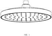
FIG. 1 illustrates a perspective view of an appearance ofEmbodiment 1 of the present disclosure; -
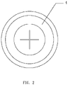
FIG. 2 illustrates a structural view of a water shut-off sealing member ofEmbodiment 1 of the present disclosure; -
FIG. 3 illustrates a cross-sectional view of a shower ofEmbodiment 1 of the present disclosure when water is turned on; -
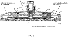
FIG. 4 illustrates a cross-sectional view of the shower ofEmbodiment 1 of the present disclosure when the water is shut off; -
FIG. 5 illustrates a cross-sectional view of a shower ofEmbodiment 2 of the present disclosure when water is turned on; -
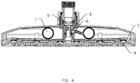
FIG. 6 illustrates a cross-sectional view of the shower ofEmbodiment 2 of the present disclosure when the water is shut off. - The technical solutions of embodiments of the present disclosure will be clearly and completely described below in combination with the accompanying drawings and embodiments of the present disclosure. It is obvious that the described embodiments are only some embodiments of the present disclosure and are not all embodiments, and the present disclosure covers all other embodiments provided they are made without creative works by those having ordinary skill in the art based on the embodiments of the present disclosure.
- In the description of the present disclosure, it should be noted that the terms "upper", "lower", "inner", "outer", "top/bottom", etc. indicate an orientation or a positional relationship based on the orientation shown in the drawings. The positional relationship is only for convenience for describing the present disclosure and simplifying the description, rather than indicating or implying that the pointed device or the pointed element must have a specific orientation or be constructed and operated in the specific orientation, and therefore should not be understood as a limitation of the present disclosure. In addition, the terms "first" and "second" are only used for descriptive purposes and should not be understood as indicating or implying relative importance.
- In the description of the present disclosure, unless otherwise described, it should be noted that the terms "installed", "disposed with", "socketed/sleeved", "connected", etc., should be broadly understood, such as "connection" can be a wall-mounted connection, a detachable connection, or an integral connection, a mechanical connection, an electrical connection, a direct connection, an indirect connection through an intermediate medium, and a connection between two components. For those of ordinary skill in the art, the specific meaning of the above-mentioned terms in the present disclosure can be understood under specific conditions.
- This embodiment provides a method for shutting off water, which is applied to a water outlet device. The method comprises a step that when water is shut off, negative pressure is released at a connection of a
variable chamber 1 and awater outlet chamber 2, so that a volume of thevariable chamber 1 increases to form a negative pressure chamber to suck residual water in thewater outlet chamber 2 into the negative pressure chamber. When the water is shut off, the residual water in thewater outlet chamber 2 can be directly sucked into the negative pressure chamber to form quick stopping effects of shutting off of water by this step. In this way, when the water is shut off, out-flowing water from the water outlet device can be shut off immediately such that the water is shut off without waiting for buoyancy of the water in the pressure chamber decreasing, just like the existing techniques. In this way, sensitivity is relatively high. - The aforementioned technical solution achieves quick stopping of the shutting off of water. In order to achieve a volume of the
variable chamber 1 being variable, this embodiment further comprises a step that the volume of thevariable chamber 1 of the water outlet device decreases when the water is turned on. In this way, the volume of thevariable chamber 1 is relatively small when the water is turned on, which provides a basis for increasing the volume when the water is shut off. - In order to achieve the volume of the
variable chamber 1 changing, when the water is turned on, a negative pressure is generated at the connection of thevariable chamber 1 and thewater outlet chamber 2. Air in thevariable chamber 1 enters into thewater outlet chamber 2, and the volume of thevariable chamber 1 decreases. When the water is shut off, the negative pressure disappears at the connection of thevariable chamber 1 and thewater outlet chamber 2, thevariable chamber 1 can expand due to an elastic restoring force, and the volume of thevariable chamber 1 increases. Further, as thevariable chamber 1 is independently disposed outside of thewater outlet chamber 2, the decreasing of the volume of thevariable chamber 1 does not depend on water pressure acting on thevariable chamber 1 when the water is turned on. Therefore, even in case that the water pressure is relatively low when the water is turned on, the water can flow out smoothly. - The aforementioned technical solution is suitably applied to a state in which the water outlet device is maintained horizontal. Therefore, in this state, after the water is shut off, everywhere in the
water outlet chamber 2 is filled with water, and the water in thewater outlet chamber 2 can be only sucked into thevariable chamber 1 by the negative pressure. Once the water outlet device is inclined, the residual water in thewater outlet chamber 2 will flow to an inclined side, causing a part of thewater outlet chamber 2 to be in communication with external atmospheric air pressure. At this time, thewater outlet chamber 2 cannot generate the negative pressure, and the residual water cannot be maintained in thewater outlet chamber 2. Therefore, the residual water will still drip from a water outlet hole, and the quick stopping effects of the shutting off of water cannot be achieved. - Therefore, in order to solve the aforementioned technical problems, this embodiment further provides a method for shutting off water, which is applied to the water outlet device. The method comprises a step that when the water is shut off, a volume of air in the
water outlet chamber 2 of the water outlet device increases to generate a negative pressure, so that a water shut-off sealingmember 4 at thewater outlet hole 3 is hermetically sealed with the connection of thewater outlet chamber 2 and thewater outlet hole 3. - Due to the water shut-off sealing
member 4 being added, when the residual water in thewater outlet chamber 2 is sucked into thevariable chamber 1, the volume of the air in thewater outlet chamber 2 increases to generate the negative pressure. Therefore, a pressure difference is formed at two sides of the water shut-off sealingmember 4. Therefore, the water shut-off sealingmember 4 is upwardly arched, and a connection of thewater outlet hole 3 and thewater outlet chamber 2 is hermetically sealed. In this way, even in case the water outlet device is inclined, no air will enter into thewater outlet chamber 2 from thewater outlet hole 3, which ensures that the quick stopping effects of the shutting off of water at any angle is maintained. - Further, water with low pressure can be turned on using this method. When the water is turned on, a pressure of out-flowing water in the
water outlet chamber 2 is applied to the water shut-off sealingmember 4 to push the water shut-off sealingmember 4 to move downward, so that the connection of thewater outlet hole 3 and thewater outlet chamber 2 is reset. Therefore, the water pressure required is relatively low using this turn-on method, and rapidly turning on water can be achieved under a low pressure. - In order to achieve the aforementioned method for shutting off water, this embodiment provides two applicable structures. It should be noted that this embodiment uses a top spray shower as an example. However, a structure of this part can be also applied to other water outlet devices, which is a simple replacement of this embodiment and will not be repeatedly described herewith.
- Referring to
FIGS. 1 to 4 , this embodiment provides a water outlet device, which comprises avariable chamber 1 and awater outlet chamber 2 that are disposed in the water outlet device. Thevariable chamber 1 is in communication with thewater outlet chamber 2. Thevariable chamber 1 is independently disposed outside of thewater outlet chamber 2. Thevariable chamber 1 being independently disposed outside of thewater outlet chamber 2 means that when water flows through thewater outlet chamber 2, the water will not enter into thevariable chamber 1 from a connection of thevariable chamber 1 and thewater outlet chamber 2. For example, thevariable chamber 1 can be disposed on an outer periphery of thewater outlet chamber 2, and a center line of thevariable chamber 1 can be perpendicular to a water flow direction. Or, the center line of thevariable chamber 1 and the water flow direction can form an angle. Thevariable chamber 1 being independently disposed outside of the water flow direction of thewater outlet chamber 2 means that when the water flows through thewater outlet chamber 2, the water will not enter into thevariable chamber 1 from the connection of thevariable chamber 1 and thewater outlet chamber 2. - The
water outlet chamber 2 comprises aflow passage 5 having variable cross-sectional areas for accelerating the flowing-through water. Preferably, thevariable chamber 1 is disposed on an outer periphery of theflow passage 5 having variable cross sections, and theflow passage 5 having the variable cross-sectional areas comprises a throughhole 6 in communication with thevariable chamber 1. In this embodiment, the through hole comprises afirst opening 61 disposed on thevariable chamber 1 and asecond opening 62 disposed on theflow passage 5 having the variable cross sections. Thefirst opening 61 is in communication with thesecond opening 62 through thewater outlet chamber 2. In the aforementioned water outlet device, after installation, when the water is turned on for a first time, the water is accelerated through the flow passage having decreased cross-sectional areas. According to the Bernoulli equation, kinetic energy increases, pressure energy decreases, so that negative pressure is generated at theflow passage 5 having the variable cross-sectional areas. Thesecond opening 62 disposed on theflow passage 5 having the variable cross-sectional areas is in communication with thefirst opening 61 of thevariable chamber 1 to enable air in thevariable chamber 1 to be sucked away, so that thevariable chamber 1 contracts and a volume of thevariable chamber 1 decreases due to the external atmospheric air pressure. When the water is shut off, the negative pressure at thesecond opening 62 disappears (which restores to a state of approximately atmospheric air pressure), and the volume of thevariable chamber 1 increases. In this way, the volume of thevariable chamber 1 changes following with a change between a water turn-on state and a water shut-off state, so that thevariable chamber 1 forms a negative pressure chamber when the water is shut off. - In this embodiment, a piston 7 is disposed in the water outlet device, and the piston 7 is hermetically sealed to an inner wall of the water outlet device to form the
variable chamber 1. A side of the piston 7 facing a fixed end of the variable chamber is connected to a spring 8. When the volume of thevariable chamber 1 decreases, the spring 8 is squeezed by the piston 7 to accumulate an elastic restoring force. When the negative pressure at thesecond opening 62 disappears, the piston 7 moves in a direction along which the volume of thevariable chamber 1 increases under a combined action of the elastic restoring force and the atmospheric air pressure, so that the volume of thevariable chamber 1 increases to form a negative pressure chamber and the residual water in thewater outlet chamber 2 is sucked into thevariable chamber 1 through thefirst opening 61 and thesecond opening 62. When the water is turned on each time hereafter, the water is accelerated through the flow passage having decreased cross-sectional areas. According to the Bernoulli equation, the kinetic energy increases, the pressure energy decreases, therefore, the negative pressure is generated at theflow passage 5 having the variable cross-sectional areas, and thesecond opening 62 of theflow passage 5 having variable cross-sectional areas is in communication with thefirst opening 61 of thevariable chamber 1, so that the air in thevariable chamber 1 and the water sucked into thevariable chamber 1 when the water is shut off in a previous time is sucked into thewater outlet chamber 2. In this embodiment, a movement direction of the piston is perpendicular to the water flow direction in thewater outlet chamber 2. - In order to achieve a hermetically sealed connection of the piston 7 and the inner wall of the water outlet device, the piston 7 is connected to the inner wall of the water outlet device through two Y-shaped sealing rings 9 and 10. The two Y-shaped sealing rings 9 and 10 are disposed in opposite directions, so that one Y-shaped
sealing ring 9 is used to hermetically seal and isolate the external atmosphere air from thevariable chamber 1, and the other Y-shapedsealing ring 10 is used to hermetically seal the residual water sucked into thevariable chamber 1 when the water is shut off, so as to prevent the residual water from flowing out from this position. - In order to further achieve the quick stopping effects of the shutting off of water at any angle, in this embodiment, a water shut-off sealing
member 4 is disposed on a connection of thewater outlet hole 3 and thewater outlet chamber 2. - When the water is shut off, the residual water in the
water outlet chamber 2 is sucked into thevariable chamber 1, so that a negative pressure is generated in thewater outlet chamber 2. The pressure difference between the two sides of the water shut-off sealingmember 4 causes the water shut-off sealingmember 4 to move to a position in which the connection of thewater outlet hole 3 and thewater outlet chamber 2 is hermetically sealed. - Furthermore, the water shut-off sealing
member 4 is a one-way sheet having a cut opening. When the water is shut off, the residual water in thewater outlet chamber 2 is sucked into thevariable chamber 1, so that the volume of the air in thewater outlet chamber 2 increases to generate the negative pressure. The external atmospheric air pressure acts on the one-way sheet having the cut opening, so that the one-way sheet is upwardly arched to achieve the quick stopping effects of the shutting off of water. At the same time, the water received in thewater outlet hole 3 is backwardly sucked due to the one-way sheet upwardly arching, so that there is no residual water on a surface of thewater outlet hole 3. In this way, even in case that the water outlet device is not in the horizontal state, external atmospheric air will not enter into thewater outlet chamber 2, and quick stopping of the shutting off of water at any angle can be achieved. When water is turned on, the air in thevariable chamber 1 enters into thewater outlet chamber 2, and a pressure of the out-flowing water is applied to the water shut-off sealingmember 4 to push the water shut-off sealingmember 4 to move downward and the cut opening of the water shut-off sealingmember 4 is opened, so that the connection of thewater outlet hole 3 and thewater outlet chamber 2 is reset. - Referring to
FIGS. 5 and6 , this embodiment differs fromEmbodiment 1 in that thevariable chamber 1 is an elastic chamber made of an elastic material. When the volume of thevariable chamber 1 decreases, the elastic material contracts to generate an elastic restoring force. This can also enable the volume of thevariable chamber 1 to change following with a change between a water turn-on state and a water shut-off state, so that thevariable chamber 1 forms a negative pressure chamber when the water is shut off. In this embodiment, the elastic material is selected from elastic silicone. The rest is the same asEmbodiment 1 and will not be repeatedly described herewith. - The invention may be summarized as follows:
- 1. A method for shutting off water that is applied to a water outlet device, characterized in that, enabling a volume of a variable chamber to increase to form a negative pressure chamber to suck residual water in a water outlet chamber into the negative pressure chamber by releasing negative pressure at a connection of the variable chamber and the water outlet chamber when the water is shut off.
- 2. The method according to
item 1, characterized in that, enabling the volume of the variable chamber to decrease by generating the negative pressure at the connection of the variable chamber and the water outlet chamber when the water is turned on. - 3. A method for shutting off water that is applied to a water outlet device, characterized in that, enabling a water shut-off sealing member to hermetically seal a connection of a water outlet hole and a water outlet chamber by a volume of air in the water outlet chamber of the water outlet device increasing to generate negative pressure when the water is shut off.
- 4. The method according to
item 3, characterized in that, enabling a volume of a variable chamber to increase to form a negative pressure chamber to suck residual water in the water outlet chamber into the negative pressure chamber by releasing the negative pressure at a connection of the variable chamber and the water outlet chamber when the water is shut off. - 5. The method according to
item 3 and/or 4, characterized in that, enabling a volume of a variable chamber to decrease by generating the negative pressure at a connection of a variable chamber and the water outlet chamber when the water is turned on. - 6. A water outlet device, characterized in that, which comprises a variable chamber and a water outlet chamber that are disposed in the water outlet device, the variable chamber is in communication with the water outlet chamber, and the variable chamber is independently disposed outside of the water outlet chamber; and
volumes of the variable chamber are not equal when water is turned on and when the water is shut off to enable the variable chamber to generate a negative pressure chamber when the water is shut off. - 7. The water outlet device according to
item 6, characterized in that, the variable chamber is in communication with the water outlet chamber through a through hole; and
when the water is turned on, negative pressure is generated at the through hole, and the volume of the variable chamber decreases; and when the water is shut off, the negative pressure at the through hole disappears, and the volume of the variable chamber increases to form the negative pressure chamber. - 8. The water outlet device according to item 7, characterized in that, the water outlet chamber comprises a flow passage having variable cross-sectional areas, after the water is accelerated through the flow passage having the variable cross-sectional areas, the negative pressure is generated at the through hole.
- 9. The water outlet device according to any one or more of
items 6 to 8, characterized in that, a piston is disposed in the water outlet device, and the piston is hermetically sealed to an inner wall of the water outlet device to form the variable chamber; and the piston is connected to a spring, when the volume of the variable chamber decreases, the spring is squeezed by the piston to accumulate an elastic restoring force. - 10. The water outlet device according to any one or more of
items 6 to 9, characterized in that, the variable chamber is an elastic chamber made of elastic material, when the volume of the variable chamber decreases, the elastic material contracts to generate an elastic restoring force. - 11. A water outlet device, characterized in that, which comprises a variable chamber and a water outlet chamber that are disposed in the water outlet device, the variable chamber is in communication with the water outlet chamber; the variable chamber is independently disposed outside of the water outlet chamber; and
a flow passage having variable cross-sectional areas comprises a through hole in communication with the variable chamber, and the water outlet chamber comprises the flow passage having the variable cross-sectional areas for accelerating flowing-through water to generate a negative pressure at the through hole. - 12. The water outlet device according to item 11, characterized in that, when the water is turned on, the negative pressure is generated at the through hole, and a volume of the variable chamber decreases; and when the water is shut off, the negative pressure disappears at the through hole, and the volume of the variable chamber increases to form a negative pressure chamber.
- 13. The water outlet device according to item 11 and/or 12, characterized in that, a piston is disposed in the water outlet device, and the piston is hermetically sealed to an inner wall of the water outlet device to form the variable chamber; and the piston is connected to a spring, when a volume of the variable chamber decreases, the spring is squeezed by the piston to accumulate an elastic restoring force.
- 14. The water outlet device according to any one or more of items 11 to 13, characterized in that, the variable chamber is an elastic chamber made of elastic material, when a volume of the variable chamber decreases, the elastic material contracts to generate an elastic restoring force.
- 15. A water outlet device, characterized in that, which comprises a variable chamber and a water outlet chamber that are disposed in the water outlet device, the variable chamber is in communication with the water outlet chamber; and
a Venturi structure is disposed in the water outlet device for generating negative pressure at a connection of the variable chamber and the water outlet chamber when water is turned on. - 16. The water outlet device according to item 15, characterized in that, the Venturi structure comprises a through hole for the connection of the variable chamber and the water outlet chamber and a flow passage having variable cross-sectional areas disposed in the water outlet chamber.
- 17. The water outlet device according to item 16, characterized in that, when the water is turned on, the negative pressure is generated at the through hole, and a volume of the variable chamber decreases; and when the water is shut off, the negative pressure disappears at the through hole, and the volume of the variable chamber increases to form a negative pressure chamber.
- 18. The water outlet device according to any one or more of items 15 to 17, characterized in that, a piston is disposed in the water outlet device, and the piston is hermetically sealed to an inner wall of the water outlet device to form the variable chamber; and the piston is connected to a spring, when a volume of the variable chamber decreases, the spring is squeezed by the piston to accumulate an elastic restoring force.
- 19. The water outlet device according to any one or more of items 15 to 18, characterized in that, the variable chamber is an elastic chamber made of elastic material, when a volume of the variable chamber decreases, the elastic material contracts to generate elastic restoring force.
- 20. A water outlet device, characterized in that, which comprises a variable chamber and a water outlet chamber that are disposed in the water outlet device and a water shut-off sealing member that is disposed at a connection of a water outlet hole and the water outlet chamber; and
when water is shut off, residual water in the water outlet chamber is sucked into the variable chamber, a negative pressure is generated in the water outlet chamber, and a pressure difference between two sides of the water shut-off sealing member enables the water shut-off sealing member to be deformed to reach a position in which a connection of the water outlet hole and the water outlet chamber is hermetically sealed. - 21. The water outlet device according to item 20, characterized in that, when the water is turned on, air in the variable chamber enters into the water outlet chamber, and water pressure is applied to the water shut-off sealing member to enable the water outlet hole to be in communication with the water outlet chamber.
- 22. The water outlet device according to item 20 and/or 21, characterized in that, the water shut-off sealing member is a one-way sheet having a cut opening.
- 23. The water outlet device according to any one or more of items 20 to 22, characterized in that, the variable chamber is independently disposed outside of the water outlet chamber, and the variable chamber is in communication with the water outlet chamber through a through hole; and
when the water is turned on, negative pressure is generated at the through hole, and a volume of the variable chamber decreases; and when the water is shut off, the negative pressure disappears at the through hole, and the volume of the variable chamber increases to form a negative pressure chamber. - 24. The water outlet device according to item 23, characterized in that, the water outlet chamber comprises a flow passage having variable cross-section areas, after the water is accelerated through the flow passage having the variable cross-sectional areas, the negative pressure is generated at the through hole.
- 25. The water outlet device according to any one or more of items 20 to 24, characterized in that, a piston is disposed in the water outlet device, and the piston is hermetically connected to an inner wall of the water outlet device to form the variable chamber; and the piston is connected to a spring, when a volume of the variable chamber decreases, the spring is squeezed by the piston to accumulate an elastic restoring force.
- 26. The water outlet device according to any one or more of items 20 to 25, characterized in that, the variable chamber is an elastic chamber made of elastic material, when a volume of the variable chamber decreases, the elastic material contracts to generate an elastic restoring force.
- 27. A water outlet device, characterized in that, which comprises a variable chamber and a water outlet chamber that are disposed in the water outlet device and a water shut-off sealing member that is disposed at a connection of a water outlet hole and the water outlet chamber, and the variable chamber is independently arranged outside of the water outlet chamber;
- volumes of the variable chamber are not equal when water is turned on and when the water is shut off to enable the variable chamber to form a negative pressure chamber when the water is shut off; and
- when the water is shut off, a pressure difference between two sides of the water shut-off sealing member enables the water shut-off sealing member to be deformed to reach a position in which the connection of the water outlet hole and the water outlet chamber is hermetically sealed.
- 28. The water outlet device according to item 27, characterized in that, when the water is turned on, air in the variable chamber enters into the water outlet chamber, and water pressure is applied to the water shut-off sealing member to enable the water outlet hole to be in communication with the water outlet chamber.
- 29. The water outlet device according to item 27 and/or 28, characterized in that, the water shut-off sealing member is a one-way sheet with a cut opening.
- 30. The water outlet device according to any one or more of items 27 to 29, characterized in that,
- the variable chamber is in communication with the water outlet chamber through a through hole; and
- when the water is turned on, negative pressure is generated at the through hole, and the volume of the variable chamber decreases; and when the water is shut off, the negative pressure disappears at the through hole, and the volume of the variable chamber increases to form a negative pressure chamber.
- 31. The water outlet device according to item 30, characterized in that, the water outlet chamber comprises a flow passage having variable cross-section areas, after the water is accelerated through the flow passage having the variable cross-sectional areas, the negative pressure is generated at the through hole.
- 32. The water outlet device according to any one or more of items 27 to 31, characterized in that, a piston is disposed in the water outlet device, and the piston is hermetically connected to an inner wall of the water outlet device to form the variable chamber; and the piston is connected to a spring, when the volume of the variable chamber decreases, the spring is squeezed by the piston to accumulate an elastic restoring force.
- 33. The water outlet device according to any one or more of items 27 to 32, characterized in that, the variable chamber is an elastic chamber made of elastic material, when the volume of the variable chamber decreases, the elastic material contracts to generate an elastic restoring force.
- 34. A water outlet device, characterized in that, which comprises a variable chamber and a water outlet chamber that are disposed in the water outlet device and a water shut-off sealing member that is disposed at a connection of a water outlet hole and the water outlet chamber;
- a Venturi structure is disposed in the water outlet device for generating negative pressure at a connection of the variable chamber and the water outlet chamber when water is turned on; and
- when the water is shut off, a pressure difference between two sides of the water shut-off sealing member enables the water shut-off sealing member to be deformed to reach a position in which the connection of the water outlet hole and the water outlet chamber is hermetically sealed.
- 35. The water outlet device according to item 34, characterized in that, when the water is turned on, air in the variable chamber enters into the water outlet chamber, and water pressure is applied to the water shut-off sealing member to enable the water outlet hole to be in communication with the water outlet chamber.
- 36. The water outlet device according to item 34 and/or 35, characterized in that, the water shut-off sealing member is a one-way sheet with a cut opening.
- 37. The water outlet device according to any one or more of items 34 to 36, characterized in that, the Venturi structure comprises a through hole for a connection of the variable chamber and the water outlet chamber and a flow passage having variable cross-sectional areas disposed in the water outlet chamber.
- 38. The water outlet device according to item 37, characterized in that, when the water is turned on, a negative pressure is generated at the through hole, and a volume of the variable chamber decrease; and when the water is shut off, the negative pressure disappears at the through hole, and the volume of the variable chamber increases to form a negative pressure chamber.
- 39. The water outlet device according to any one or more of items 34 to 38, characterized in that, a piston is disposed in the water outlet device, and the piston is hermetically connected to an inner wall of the water outlet device to form the variable chamber; and the piston is connected to a spring, when a volume of the variable chamber decreases, the spring is squeezed by the piston to accumulate an elastic restoring force.
- 40. The water outlet device according to any one or more of items 34 to 39, characterized in that, the variable chamber is an elastic chamber made of elastic material, when a volume of the variable chamber decreases, the elastic material contracts to generate an elastic restoring force.
- The invention may also be summarized as follows: A method for shutting off water that is applied to a water outlet device, which comprises enabling a volume of a variable chamber to increase to form a negative pressure chamber to suck residual water in a water outlet chamber into the negative pressure chamber by releasing negative pressure at a connection of the variable chamber and the water outlet chamber when the water is shut off. A method for shutting off water that is applied to a water outlet device, which comprises enabling a water shut-off sealing member to hermetically seal a connection of a water outlet hole and a water outlet chamber by a volume of air in the water outlet chamber of the water outlet device increasing to generate negative pressure when the water is shut off. A water outlet device is provided.
- The aforementioned embodiments are merely some embodiments of the present disclosure, and the scope of the disclosure of is not limited thereto. Thus, it is intended that the present disclosure cover any modifications and variations of the presently presented embodiments provided they are made without departing from the appended claims and the specification of the present disclosure.
Claims (16)
- A method for shutting off water that is applied to a water outlet device, characterized in that, enabling a water shut-off sealing member to hermetically seal a connection of a water outlet hole and a water outlet chamber by a volume of air in the water outlet chamber of the water outlet device increasing to generate negative pressure when the water is shut off.
- The method according to claim 1, characterized in that, enabling a volume of a variable chamber to increase to form a negative pressure chamber to suck residual water in the water outlet chamber into the negative pressure chamber by releasing the negative pressure at a connection of the variable chamber and the water outlet chamber when the water is shut off.
- The method according to claim 1 and/or 2, characterized in that, enabling a volume of a variable chamber to decrease by generating the negative pressure at a connection of a variable chamber and the water outlet chamber when the water is turned on.
- A water outlet device, characterized in that, which comprises a variable chamber and a water outlet chamber that are disposed in the water outlet device, the variable chamber is in communication with the water outlet chamber, and the variable chamber is independently disposed outside of the water outlet chamber; and
volumes of the variable chamber are not equal when water is turned on and when the water is shut off to enable the variable chamber to generate a negative pressure chamber when the water is shut off. - A water outlet device, characterized in that, which comprises a variable chamber and a water outlet chamber that are disposed in the water outlet device, the variable chamber is in communication with the water outlet chamber; the variable chamber is independently disposed outside of the water outlet chamber; and
a flow passage having variable cross-sectional areas comprises a through hole in communication with the variable chamber, and the water outlet chamber comprises the flow passage having the variable cross-sectional areas for accelerating flowing-through water to generate a negative pressure at the through hole. - A water outlet device, characterized in that, which comprises a variable chamber and a water outlet chamber that are disposed in the water outlet device and a water shut-off sealing member that is disposed at a connection of a water outlet hole and the water outlet chamber; and
when water is shut off, residual water in the water outlet chamber is sucked into the variable chamber, a negative pressure is generated in the water outlet chamber, and a pressure difference between two sides of the water shut-off sealing member enables the water shut-off sealing member to be deformed to reach a position in which a connection of the water outlet hole and the water outlet chamber is hermetically sealed. - The water outlet device according to any one or more of claims 4 to 6, characterized in that, the variable chamber is independently disposed outside of the water outlet chamber, and the variable chamber is in communication with the water outlet chamber through a through hole; and
when the water is turned on, negative pressure is generated at the through hole, and a volume of the variable chamber decreases; and when the water is shut off, the negative pressure disappears at the through hole, and the volume of the variable chamber increases to form a negative pressure chamber. - A water outlet device, characterized in that, which comprises a variable chamber and a water outlet chamber that are disposed in the water outlet device and a water shut-off sealing member that is disposed at a connection of a water outlet hole and the water outlet chamber, and the variable chamber is independently arranged outside of the water outlet chamber;volumes of the variable chamber are not equal when water is turned on and when the water is shut off to enable the variable chamber to form a negative pressure chamber when the water is shut off; andwhen the water is shut off, a pressure difference between two sides of the water shut-off sealing member enables the water shut-off sealing member to be deformed to reach a position in which the connection of the water outlet hole and the water outlet chamber is hermetically sealed.
- The water outlet device according to any one or more of claims 4 to 8, characterized in that,the variable chamber is in communication with the water outlet chamber through a through hole; andwhen the water is turned on, negative pressure is generated at the through hole, and the volume of the variable chamber decreases; and when the water is shut off, the negative pressure disappears at the through hole, and the volume of the variable chamber increases to form a negative pressure chamber.
- The water outlet device according to any one or more of claims 7 to 9, characterized in that, the water outlet chamber comprises a flow passage having variable cross-section areas, after the water is accelerated through the flow passage having the variable cross-sectional areas, the negative pressure is generated at the through hole.
- A water outlet device, characterized in that, which comprises a variable chamber and a water outlet chamber that are disposed in the water outlet device and a water shut-off sealing member that is disposed at a connection of a water outlet hole and the water outlet chamber;a Venturi structure is disposed in the water outlet device for generating negative pressure at a connection of the variable chamber and the water outlet chamber when water is turned on; andwhen the water is shut off, a pressure difference between two sides of the water shut-off sealing member enables the water shut-off sealing member to be deformed to reach a position in which the connection of the water outlet hole and the water outlet chamber is hermetically sealed.
- The water outlet device according to any one or more of claims 6 to 11, characterized in that, when the water is turned on, air in the variable chamber enters into the water outlet chamber, and water pressure is applied to the water shut-off sealing member to enable the water outlet hole to be in communication with the water outlet chamber.
- The water outlet device according to claim 11 and/or 12, characterized in that, the Venturi structure comprises a through hole for a connection of the variable chamber and the water outlet chamber and a flow passage having variable cross-sectional areas disposed in the water outlet chamber.
- The water outlet device according to any one or more of claims 5 to 13, characterized in that, when the water is turned on, a negative pressure is generated at the through hole, and a volume of the variable chamber decrease; and when the water is shut off, the negative pressure disappears at the through hole, and the volume of the variable chamber increases to form a negative pressure chamber.
- The water outlet device according to any one or more of claims 4 to 14, characterized in that, a piston is disposed in the water outlet device, and the piston is hermetically sealed to an inner wall of the water outlet device to form the variable chamber; and the piston is connected to a spring, when a volume of the variable chamber decreases, the spring is squeezed by the piston to accumulate an elastic restoring force.
- The water outlet device according to any one or more of claims 4 to 15, characterized in that, the variable chamber is an elastic chamber made of elastic material, when a volume of the variable chamber decreases, the elastic material contracts to generate an elastic restoring force.
Applications Claiming Priority (1)
| Application Number | Priority Date | Filing Date | Title |
|---|---|---|---|
| CN202110362690.5A CN115138491B (en) | 2021-04-02 | 2021-04-02 | Water shut-off method and water outlet device |
Publications (1)
| Publication Number | Publication Date |
|---|---|
| EP4067584A1 true EP4067584A1 (en) | 2022-10-05 |
Family
ID=81325706
Family Applications (1)
| Application Number | Title | Priority Date | Filing Date |
|---|---|---|---|
| EP22166583.9A Pending EP4067584A1 (en) | 2021-04-02 | 2022-04-04 | Method for shutting off water and a water outlet device |
Country Status (4)
| Country | Link |
|---|---|
| US (1) | US12036567B2 (en) |
| EP (1) | EP4067584A1 (en) |
| JP (1) | JP7292350B2 (en) |
| CN (2) | CN119387059A (en) |
Families Citing this family (3)
| Publication number | Priority date | Publication date | Assignee | Title |
|---|---|---|---|---|
| CN116877739B (en) * | 2023-06-08 | 2025-10-24 | 深圳华星恒泰泵阀有限公司 | A three-way check valve structure for preventing side leakage of a floor scrubber nozzle |
| CN118513160B (en) * | 2024-02-21 | 2025-12-12 | 厦门松霖科技股份有限公司 | A structure that stops water flow immediately upon turning off and an overhead shower head |
| CN119747116B (en) * | 2025-02-26 | 2025-06-06 | 台州丰华铜业有限公司 | A shower head |
Citations (3)
| Publication number | Priority date | Publication date | Assignee | Title |
|---|---|---|---|---|
| EP2767349A1 (en) * | 2013-02-13 | 2014-08-20 | Jiangmen Fenix Shower Products Technology Co., Ltd. | An air-water mixing shower |
| DE202015009413U1 (en) * | 2015-04-09 | 2017-07-05 | Husqvarna Ab | Spray head and spray device |
| US20190344301A1 (en) * | 2016-12-21 | 2019-11-14 | Lidor Zabari | Self-sealing shower head with disinfectant |
Family Cites Families (18)
| Publication number | Priority date | Publication date | Assignee | Title |
|---|---|---|---|---|
| US4275843A (en) * | 1979-11-14 | 1981-06-30 | Stanadyne, Inc. | Automatically adjustable shower head |
| GB2270363B (en) * | 1992-09-02 | 1996-05-15 | Kinetrol Ltd | Flow control devices |
| JPH0754702Y2 (en) * | 1993-03-31 | 1995-12-18 | 光陽産業株式会社 | Gas tap |
| ES2106393T3 (en) * | 1993-08-17 | 1997-11-01 | Kwc Ag | SANITARY PROTECTION DEVICE TO PREVENT THE RETURN OF WATER. |
| DE19952187A1 (en) * | 1999-10-29 | 2001-05-03 | Grohe Armaturen Friedrich | Shower head for sanitary purposes, with at least one water outlet aperture in bottom part offset upstream to act as ventilation device |
| CN100471577C (en) * | 2006-01-17 | 2009-03-25 | 潘尧钊 | Water outlet control mechanism of shower head |
| CN100465490C (en) * | 2006-12-26 | 2009-03-04 | 常州纺织服装职业技术学院 | Time-delay self-closing water saving valve |
| IT1396495B1 (en) * | 2009-02-24 | 2012-12-14 | Nikles Tec Italia Srl | DISTRIBUTION DEVICE FOR A THROUGH WATER JET |
| US8851398B2 (en) * | 2009-11-18 | 2014-10-07 | Xiamen Solex High-Tech Industries Co., Ltd. | Overhead shower and its switching method thereof |
| DE102010021735A1 (en) * | 2010-05-21 | 2011-11-24 | Hansgrohe Ag | Head shower, has jet disk closing housing and comprising jet outlet openings, and adapter guided into inner side of housing and provided for outlet opening of removable container or hose guided into outlet opening |
| CN102366739B (en) * | 2011-08-26 | 2013-08-28 | 厦门松霖科技有限公司 | Residual water drainage and water suction non-return mechanism |
| CN102527529B (en) * | 2011-12-20 | 2013-12-25 | 厦门松霖科技有限公司 | Sprinkler with function of alternately spraying water |
| US9222599B2 (en) * | 2013-02-05 | 2015-12-29 | Highplus International Co., Ltd. | Self-closing water-saving valve assembly |
| CN103240199A (en) * | 2013-04-11 | 2013-08-14 | 王思源 | Dripless pressure-stabilized sprinkler |
| AU2014202801A1 (en) * | 2013-06-07 | 2015-01-15 | Foreno Tapware (Nz) Limited | Apparatus for controlling a flow of fluid |
| US9677176B2 (en) * | 2013-07-03 | 2017-06-13 | Novellus Systems, Inc. | Multi-plenum, dual-temperature showerhead |
| CN210646887U (en) * | 2019-06-26 | 2020-06-02 | 九牧厨卫股份有限公司 | Water outlet device capable of stopping immediately after being closed and shower head |
| CN216631236U (en) * | 2021-04-02 | 2022-05-31 | 厦门松霖科技股份有限公司 | Water outlet device |
-
2021
- 2021-04-02 CN CN202411383863.1A patent/CN119387059A/en active Pending
- 2021-04-02 CN CN202110362690.5A patent/CN115138491B/en active Active
- 2021-11-01 JP JP2021178986A patent/JP7292350B2/en active Active
-
2022
- 2022-04-04 EP EP22166583.9A patent/EP4067584A1/en active Pending
- 2022-04-04 US US17/712,720 patent/US12036567B2/en active Active
Patent Citations (3)
| Publication number | Priority date | Publication date | Assignee | Title |
|---|---|---|---|---|
| EP2767349A1 (en) * | 2013-02-13 | 2014-08-20 | Jiangmen Fenix Shower Products Technology Co., Ltd. | An air-water mixing shower |
| DE202015009413U1 (en) * | 2015-04-09 | 2017-07-05 | Husqvarna Ab | Spray head and spray device |
| US20190344301A1 (en) * | 2016-12-21 | 2019-11-14 | Lidor Zabari | Self-sealing shower head with disinfectant |
Also Published As
| Publication number | Publication date |
|---|---|
| CN115138491A (en) | 2022-10-04 |
| US12036567B2 (en) | 2024-07-16 |
| CN115138491B (en) | 2024-11-15 |
| US20220314244A1 (en) | 2022-10-06 |
| JP2022158853A (en) | 2022-10-17 |
| JP7292350B2 (en) | 2023-06-16 |
| CN119387059A (en) | 2025-02-07 |
Similar Documents
| Publication | Publication Date | Title |
|---|---|---|
| US12036567B2 (en) | Method of shutting off water and a water outlet device | |
| EP1671906B1 (en) | Negative-pressure valve to be used in a gripping device for panels | |
| US10508426B2 (en) | Self-adjustable gas isolator | |
| US6592098B2 (en) | Microvalve | |
| US11014115B2 (en) | Showerhead capable of discharging residual water | |
| JP5062327B2 (en) | Micro valve and valve seat member | |
| JP2019529775A (en) | Microvalve, fluid pump, and method of operating fluid pump | |
| JP6351772B2 (en) | One way valve assembly | |
| CN216631236U (en) | Water outlet device | |
| CN118513160B (en) | A structure that stops water flow immediately upon turning off and an overhead shower head | |
| KR20090027623A (en) | Anti siphon device for flush valve | |
| US6557820B2 (en) | Two-stage valve suitable as high-flow high-pressure microvalve | |
| CN110056056A (en) | A kind of drain valve and the closestool with the drain valve | |
| CN115573429A (en) | An anti-odor sewer device | |
| US20220381019A1 (en) | Pushing force converting mechanism and concealed water tank | |
| WO2025260851A1 (en) | Liquid mixing device, foaming device and liquid output apparatus | |
| CN218148712U (en) | Deodorant launching device | |
| EP3916279A1 (en) | Push switch, push switch valve core and faucet | |
| CN212745144U (en) | Vacuum sewage diaphragm valve | |
| Krusemark et al. | Micro ball valve for fluidic micropumps and gases | |
| CN219430927U (en) | Structure of water outlet box | |
| AU2018346310B2 (en) | Discharge valve system and method | |
| US2914293A (en) | Pilot controlled flush valves | |
| KR200377524Y1 (en) | Rapid isolation valve | |
| EP4095328A1 (en) | Pushing force converting mechanism and concealed water tank |
Legal Events
| Date | Code | Title | Description |
|---|---|---|---|
| PUAI | Public reference made under article 153(3) epc to a published international application that has entered the european phase |
Free format text: ORIGINAL CODE: 0009012 |
|
| STAA | Information on the status of an ep patent application or granted ep patent |
Free format text: STATUS: REQUEST FOR EXAMINATION WAS MADE |
|
| 17P | Request for examination filed |
Effective date: 20220406 |
|
| AK | Designated contracting states |
Kind code of ref document: A1 Designated state(s): AL AT BE BG CH CY CZ DE DK EE ES FI FR GB GR HR HU IE IS IT LI LT LU LV MC MK MT NL NO PL PT RO RS SE SI SK SM TR |
|
| RBV | Designated contracting states (corrected) |
Designated state(s): AL AT BE BG CH CY CZ DE DK EE ES FI FR GB GR HR HU IE IS IT LI LT LU LV MC MK MT NL NO PL PT RO RS SE SI SK SM TR |
|
| RIN1 | Information on inventor provided before grant (corrected) |
Inventor name: CAO, BIN Inventor name: LIN, FENGDE Inventor name: CHEN, DONGHAI |
|
| STAA | Information on the status of an ep patent application or granted ep patent |
Free format text: STATUS: EXAMINATION IS IN PROGRESS |
|
| 17Q | First examination report despatched |
Effective date: 20240715 |