EP4067268A1 - Machine with improved transport system - Google Patents
Machine with improved transport system Download PDFInfo
- Publication number
- EP4067268A1 EP4067268A1 EP22163643.4A EP22163643A EP4067268A1 EP 4067268 A1 EP4067268 A1 EP 4067268A1 EP 22163643 A EP22163643 A EP 22163643A EP 4067268 A1 EP4067268 A1 EP 4067268A1
- Authority
- EP
- European Patent Office
- Prior art keywords
- conveyor belt
- machine
- side edge
- straightening
- panel
- Prior art date
- Legal status (The legal status is an assumption and is not a legal conclusion. Google has not performed a legal analysis and makes no representation as to the accuracy of the status listed.)
- Granted
Links
Images


Classifications
-
- B—PERFORMING OPERATIONS; TRANSPORTING
- B65—CONVEYING; PACKING; STORING; HANDLING THIN OR FILAMENTARY MATERIAL
- B65G—TRANSPORT OR STORAGE DEVICES, e.g. CONVEYORS FOR LOADING OR TIPPING, SHOP CONVEYOR SYSTEMS OR PNEUMATIC TUBE CONVEYORS
- B65G39/00—Rollers, e.g. drive rollers, or arrangements thereof incorporated in roller-ways or other types of mechanical conveyors
- B65G39/10—Arrangements of rollers
- B65G39/12—Arrangements of rollers mounted on framework
- B65G39/16—Arrangements of rollers mounted on framework for aligning belts or chains
-
- B—PERFORMING OPERATIONS; TRANSPORTING
- B24—GRINDING; POLISHING
- B24B—MACHINES, DEVICES, OR PROCESSES FOR GRINDING OR POLISHING; DRESSING OR CONDITIONING OF ABRADING SURFACES; FEEDING OF GRINDING, POLISHING, OR LAPPING AGENTS
- B24B7/00—Machines or devices designed for grinding plane surfaces on work, including polishing plane glass surfaces; Accessories therefor
- B24B7/06—Machines or devices designed for grinding plane surfaces on work, including polishing plane glass surfaces; Accessories therefor involving conveyor belts, a sequence of travelling work-tables or the like
-
- B—PERFORMING OPERATIONS; TRANSPORTING
- B65—CONVEYING; PACKING; STORING; HANDLING THIN OR FILAMENTARY MATERIAL
- B65G—TRANSPORT OR STORAGE DEVICES, e.g. CONVEYORS FOR LOADING OR TIPPING, SHOP CONVEYOR SYSTEMS OR PNEUMATIC TUBE CONVEYORS
- B65G15/00—Conveyors having endless load-conveying surfaces, i.e. belts and like continuous members, to which tractive effort is transmitted by means other than endless driving elements of similar configuration
- B65G15/60—Arrangements for supporting or guiding belts, e.g. by fluid jets
- B65G15/64—Arrangements for supporting or guiding belts, e.g. by fluid jets for automatically maintaining the position of the belts
-
- B—PERFORMING OPERATIONS; TRANSPORTING
- B65—CONVEYING; PACKING; STORING; HANDLING THIN OR FILAMENTARY MATERIAL
- B65G—TRANSPORT OR STORAGE DEVICES, e.g. CONVEYORS FOR LOADING OR TIPPING, SHOP CONVEYOR SYSTEMS OR PNEUMATIC TUBE CONVEYORS
- B65G2203/00—Indexing code relating to control or detection of the articles or the load carriers during conveying
- B65G2203/02—Control or detection
- B65G2203/0266—Control or detection relating to the load carrier(s)
- B65G2203/0283—Position of the load carrier
Definitions
- the present invention relates to a machine with an improved transport system.
- the invention relates to a machine equipped with at least one conveyor belt for transporting the pieces to be machined and configured to perform at least one machining operation on such pieces during the relative transport.
- the invention falls within the field of the so-called "passage machines", i.e. machines configured to perform the operations and/or machining provided on moving parts.
- an object of the present invention to provide a machine with an improved transport system, which allows one or more machining and/or operations to be carried out in a precise manner on pieces of different types, including pieces of high length.
- Another object of the invention is to provide a machine with an improved transport system, which allows obtaining machined parts with a high level of precision.
- a further object of the present invention is to provide a machine with an improved transport system, which allows a high level of productivity to be achieved.
- a machine for executing at least one operation or machining operation on at least one panel or other piece comprising: a conveyor belt for conveying at least one panel or other piece according to an advancing direction; at least one side edge being defined in said conveyor belt; transversal movement means for moving said conveyor belt transversely to said advancing direction; detecting means for detecting at least the position of said at least one side edge of said conveyor belt; straightening means for straightening said at least one side edge of said conveyor belt; operative means for executing at least one operation or machining operation on at least one panel or other piece while said at least one panel or other piece is transported by said conveyor belt; and a control unit which is operatively connected with said transversal movement means and said detecting means and configured to command said transversal movement means to move said conveyor belt transversely to said advancing direction based on the position of said at least one side edge being straightened by said straightening means, said position being detected by said detecting means.
- said detecting means are configured to detect also the shape of said at least one side edge of said conveyor belt.
- said detecting means may comprise a feeler device.
- said detecting means are placed in a fixed position relative to said conveyor belt.
- said straightening means may be of a rotative type.
- said straightening means may comprise a milling cutter.
- said detecting means and said straightening means may be placed at the same branch of said conveyor belt.
- said at least one side edge of said conveyor belt may lie, substantially, on a predetermined plane which is substantially parallel to said advancing direction and substantially orthogonal to the plane on which said at least one panel or other piece lies when said at least one panel or other piece is transported by said conveyor belt.
- said operative means may comprise at least one sanding member.
- said transversal movement means may comprise a predetermined roller, on which said conveyor belt is at least partially wound, and actuating means for activating said predetermined roller.
- said actuating means may be configured to rotate said predetermined roller on a plane which is parallel to the transporting plane defined by said conveyor belt.
- said conveyor belt may be wound between a first roller and a second roller which are placed at opposite ends of said conveyor belt, and in that said predetermined roller coincides with said first roller or said second roller.
- said method comprises also the step of detecting the shape and position of said at least one side edge of said conveyor belt before executing said step of straightening said at least one side edge of said conveyor belt; and said step of straightening said at least one side edge of said conveyor belt is executed based on said shape and said position of said at least one side edge of said conveyor belt, which are detected before said step of straightening.
- 1 indicates as a whole a machine for carrying out at least one machining and/or operation on panels or pieces of other shapes.
- the machine 1 comprises a base 2, on which a conveyor belt 3 is provided for transporting panels or pieces of another type according to an advancement direction A on a XY plane formed by a first axis X and a second axis Y.
- the conveyor belt 3 comprises, in turn, a flexible belt 4 of tubular shape, i.e. having a closed profile, delimited by a first side edge 4a and a second side edge 4b, which are mutually opposite.
- the aforementioned flexible belt 4 is wound on a driven roller 5 and a driving roller 6, connected to a motor 7 to allow it to rotate around its axis.
- movement means are also provided for moving the flexible belt 4 of the conveyor belt 3 on the XY plane, orthogonally to the advancement direction A.
- Such movement means can comprise, for example, an intermediate roller 14 arranged between the driven roller 5 and the driving roller 6, parallel to these two, and a linear actuator 15, for example a pneumatic type piston-cylinder system, acting along a predetermined axis parallel to the second axis Y, for the movement of the intermediate roller 14.
- a linear actuator 15 for example a pneumatic type piston-cylinder system, acting along a predetermined axis parallel to the second axis Y, for the movement of the intermediate roller 14.
- the aforementioned intermediate roller 14 is arranged in contact with the flexible belt 4, in such a way as to place it under tension according to a third axis Z orthogonal to the XY plane.
- the intermediate roller 14 is hinged, at one of its ends, by means of a hinge, to a fixed part of the machine 1 at one side of the conveyor belt 3, and connected, at its other end, to said linear actuator 15, so that, when the movable part of the linear actuator 15 moves in a direction of said predetermined axis, the intermediate roller 14 rotates (i.e. inclines) around the rotation axis (parallel to the third axis Z) of said hinge in a first direction of rotation on the XY-plane, and that when the same movable part of the linear actuator 15 moves in the opposite direction of said predetermined axis, the intermediate roller 14 rotates (i.e. inclines) around the rotation axis of said hinge in a second direction of rotation, opposite to said first direction of rotation, in the XY-plane.
- the movement of the flexible belt 4 according to the first axis X would be obtained by rotating, or by tilting, the driven roller 5 or the driving roller 6 (the one, between the two, which is connected to the aforementioned linear actuator) on the XY-plane around the rotation axis of the aforementioned hinge.
- the transverse movement of the flexible belt 4 in the direction of the second axis Y can be obtained by means of a linear actuator (for example a pneumatic piston-cylinder system) acting along an axis substantially parallel to the first axis X on an intermediate roller arranged between the driven roller 5 or the driving roller 6, parallel to these two and having an external surface such as to create a certain degree of friction with the contact surface of the flexible belt 4.
- a linear actuator for example a pneumatic piston-cylinder system
- the machine 1 includes a control unit (not shown), which both the conveyor belt 3 and the relative motor 7, and the aforementioned handling means are operatively connected to.
- first conveyor roller 8 Upstream the conveyor belt 3, in a coplanar position with it, there is a first conveyor roller 8, namely a first plurality of idle rollers, to allow the panels to be supported and the subsequent thrust towards the conveyor belt 3.
- a second roller conveyor 9 is provided downstream the conveyor belt 3, in a position coplanar with it, namely a second plurality of idle rollers, to allow the reception of the panels leaving the conveyor belt 3 and their subsequent picking up.
- a frame 10 to support the operating means (not shown) provided for carrying out one or more machining and/or operations on the panels, or other pieces, while the latter are transported by the same conveyor belt 3 according to the advancement direction A.
- Said operating means can be arranged above the conveyor belt 3, or below said conveyor belt 3, providing areas for interrupting the belt 3 itself.
- these operating means could comprise for example one or more sanding tools, for example an abrasive roller, or a rotary disk, such as a sanding pad, or a brush, or a tool with cutting elements, or a laser machining unit for sanding or machining the upper surface of the panels transported by the conveyor belt 3.
- the aforementioned operating means could also be of another kind and allow the execution of other types of processing and/or operations, such as for example a painting operation.
- the machine 1 is also equipped with a feeler device 11 mounted, in a fixed position, in correspondence with the first lateral edge 4a of the conveyor belt 3, next to the lower branch of the latter.
- this feeler device 11 comprises a roller 12 that can idly rotate around its axis, substantially orthogonal to the plane on which the panels are advanced.
- the feeler device 11 makes it possible to detect the exact shape and position of the first lateral edge 4a of the conveyor belt 3 by precisely probing the same first lateral edge 4a.
- this detection takes place by bringing into mutual contact, by means of the aforementioned moving means, the cylindrical lateral surface of the roller 12 of the feeler device 11 and the first lateral edge 4a of the conveyor belt 3 and making the latter advance in such a way that it the same feeler device 11 can continuously detect the shape and position of said first lateral edge 4a.
- the feeler device 11 is also operatively connected to the aforementioned control unit of the machine 1.
- this rectification is performed by removing, from the first lateral edge 4a of the conveyor belt 3, the excess material in such a way as to obtain, as mentioned above, the straightness of said first lateral edge 4a.
- the straightening member 13 can be a rotary cutting member, such as a cutter, with an rotation axis directed parallel to the third axis Z.
- this rotary cutting member is mounted on a mobile slide, configured in such a way as to allow it to be moved along an axis parallel to the first axis X.
- This movement of the rotary cutting member can be performed manually, or managed automatically by the control unit through special members actuators for the relative handling.
- the rotary cutting member is first arranged in a position adjacent to the first lateral edge 4a of the conveyor belt 3, and then the rotary cutting member and the conveyor belt 3 are activated, which, by moving according to the advancement direction of A, will cause the rotary cutting member to progressively remove material from the relative first lateral edge 4a until it is completely straight.
- the machine 1 To obtain the advancement, according to a perfectly rectilinear direction (i.e. the advancement direction A), of the panels or other pieces transported by the conveyor belt 3, the machine 1 operates according to the methods described below.
- the aforementioned control unit of the machine 1 detects the actual shape and position of the first lateral edge 4a of the conveyor belt 3, bringing the latter into contact with the feeler device 11 by means of the above-mentioned movement means and activating the same feeler device 11.
- the feeler device 11 Once the feeler device 11 has performed this detection and transmitted the data relating to the exact shape and exact position of said first lateral edge 4a to the control unit, the latter commands the activation of the straightening member 13, so that this performs the rectification of the first lateral edge 4a on the basis of such data.
- the control unit detects the shape and position of the first lateral edge 4a of the conveyor belt 3 thus rectified, bringing the latter into contact with the same device feeler 11 by means of the aforementioned handling means.
- the feeler device 11 transmits the data relating to the shape and position of the first rectified lateral edge 4a to the same control unit, which will subsequently control the correct positioning of the conveyor belt 3 along the first axis X, by means of the aforementioned movement means, on the basis of said data relating to the first rectified lateral edge 4a.
- the positioning of the conveyor belt 3 along the first axis X is extremely precise, since it is performed by taking as a reference a part of the conveyor belt 3, which is perfectly straight and parallel to the second axis Y, which is precisely the first side edge 4a. following the related amendment.
- the machine 1 allows obtaining quality standards higher than those obtainable through traditional passage machines equipped with conveyor belt for handling the pieces to be treated.
- the same machine 1 also allows to significantly reduce the number of machined pieces to be rejected due to defective machining.
Landscapes
- Engineering & Computer Science (AREA)
- Mechanical Engineering (AREA)
- Feeding Of Workpieces (AREA)
- Structure Of Belt Conveyors (AREA)
- Grinding And Polishing Of Tertiary Curved Surfaces And Surfaces With Complex Shapes (AREA)
Abstract
Description
- The present invention relates to a machine with an improved transport system.
- Specifically, the invention relates to a machine equipped with at least one conveyor belt for transporting the pieces to be machined and configured to perform at least one machining operation on such pieces during the relative transport.
- The invention, therefore, falls within the field of the so-called "passage machines", i.e. machines configured to perform the operations and/or machining provided on moving parts.
- There are several passage machines in which the workpieces are transported by conveyor belts.
- However, in many cases these known machines show the disadvantage of not being able to reach high levels of precision in the machined pieces.
- This machining inaccuracy is normally due not so much to the operating means of the machine, but rather to the intrinsic imperfections of the conveyor belts, which due to their very nature have uncontrolled oscillations and movements during their operation.
- This means that the pieces transported by traditional conveyor belts are not, in many cases, in the relative theoretical position (i.e. ideal machining position), and therefore that the operating means do not operate in the exact areas of the pieces.
- For this reason, traditional machines of the aforesaid type are therefore not suitable for cases where particularly reduced machining tolerances are required.
- In the following, the description will be directed to a machine for machining panels, but it is clear that it should not be considered limited to this specific use, as it can be also extended to machines for the execution of various operations and/or machining on pieces of any shape and nature.
- In the light of the above, it is, therefore, an object of the present invention to provide a machine with an improved transport system, which allows one or more machining and/or operations to be carried out in a precise manner on pieces of different types, including pieces of high length.
- Another object of the invention is to provide a machine with an improved transport system, which allows obtaining machined parts with a high level of precision.
- A further object of the present invention is to provide a machine with an improved transport system, which allows a high level of productivity to be achieved.
- It is, therefore, specific object of the present invention a machine for executing at least one operation or machining operation on at least one panel or other piece, said machine comprising: a conveyor belt for conveying at least one panel or other piece according to an advancing direction; at least one side edge being defined in said conveyor belt; transversal movement means for moving said conveyor belt transversely to said advancing direction; detecting means for detecting at least the position of said at least one side edge of said conveyor belt; straightening means for straightening said at least one side edge of said conveyor belt; operative means for executing at least one operation or machining operation on at least one panel or other piece while said at least one panel or other piece is transported by said conveyor belt; and a control unit which is operatively connected with said transversal movement means and said detecting means and configured to command said transversal movement means to move said conveyor belt transversely to said advancing direction based on the position of said at least one side edge being straightened by said straightening means, said position being detected by said detecting means.
- Preferably according to the invention, said detecting means are configured to detect also the shape of said at least one side edge of said conveyor belt.
- Conveniently according to the invention, said detecting means may comprise a feeler device.
- Preferably according to the invention, said detecting means are placed in a fixed position relative to said conveyor belt.
- Advantageously according to the invention, said straightening means may be of a rotative type.
- Further according to the invention, said straightening means may comprise a milling cutter.
- Conveniently according to the invention, said detecting means and said straightening means may be placed at the same branch of said conveyor belt.
- Preferably according to the invention, said at least one side edge of said conveyor belt may lie, substantially, on a predetermined plane which is substantially parallel to said advancing direction and substantially orthogonal to the plane on which said at least one panel or other piece lies when said at least one panel or other piece is transported by said conveyor belt.
- Still according to the invention, said operative means may comprise at least one sanding member.
- Further according to the invention, said transversal movement means may comprise a predetermined roller, on which said conveyor belt is at least partially wound, and actuating means for activating said predetermined roller.
- Advantageously according to the invention, said actuating means may be configured to rotate said predetermined roller on a plane which is parallel to the transporting plane defined by said conveyor belt.
- Further according to the invention, said conveyor belt may be wound between a first roller and a second roller which are placed at opposite ends of said conveyor belt, and in that said predetermined roller coincides with said first roller or said second roller.
- It is further object of the present invention a method for processing at least one panel or other piece by a machine as indicated above while said conveyor belt transports said at least one panel or other piece, said method comprising the steps of: placing at least one panel or other piece on said conveyor belt and making said conveyor belt advance according to said advancing direction; straightening said at least one side edge of said conveyor belt by said straightening means; detecting, by said detecting means, at least the position of said at least one side edge of said conveyor belt which is straightened by said straightening means; moving said conveyor belt transversely to said advancing direction by said transversal movement means based on the position of said at least one side edge of said conveyor belt which is straightened by said straightening means, the position being detected by said detecting means; and executing, by said operative means, at least one operation or machining operation on said at least one panel or other piece while said at least one panel or other piece is transported by said conveyor belt.
- Preferably according to the invention, said method comprises also the step of detecting the shape and position of said at least one side edge of said conveyor belt before executing said step of straightening said at least one side edge of said conveyor belt; and said step of straightening said at least one side edge of said conveyor belt is executed based on said shape and said position of said at least one side edge of said conveyor belt, which are detected before said step of straightening.
- The present invention will be now described, for illustrative but not limitative purposes, according to its preferred embodiments, with particular reference to the figures of the enclosed drawings, wherein:
-
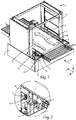
figure 1 is a first axonometric view, from the top, of a machine according to the present invention; -
figure 2 is a detail view of the detail E indicated infigure 1 ; -
figure 3 is a second axonometric view, from the bottom, of the machine shown infigure 1 ; -
figure 4 is a detail view of the detail F indicated infigure 3 ; -
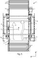
figure 5 is a top plan view of the machine illustrated infigures 1 and3 ; and -
figure 6 is a further detail view of the machine shown infigure 1 . - In the various figures the similar parts will be indicated with the same numerical references.
- With reference to the attached
figures, 1 indicates as a whole a machine for carrying out at least one machining and/or operation on panels or pieces of other shapes. - The
machine 1 comprises abase 2, on which aconveyor belt 3 is provided for transporting panels or pieces of another type according to an advancement direction A on a XY plane formed by a first axis X and a second axis Y. - The
conveyor belt 3 comprises, in turn, aflexible belt 4 of tubular shape, i.e. having a closed profile, delimited by afirst side edge 4a and asecond side edge 4b, which are mutually opposite. - The aforementioned
flexible belt 4 is wound on a drivenroller 5 and adriving roller 6, connected to amotor 7 to allow it to rotate around its axis. - In the
machine 1, movement means are also provided for moving theflexible belt 4 of theconveyor belt 3 on the XY plane, orthogonally to the advancement direction A. - Such movement means can comprise, for example, an
intermediate roller 14 arranged between the drivenroller 5 and thedriving roller 6, parallel to these two, and alinear actuator 15, for example a pneumatic type piston-cylinder system, acting along a predetermined axis parallel to the second axis Y, for the movement of theintermediate roller 14. - The aforementioned
intermediate roller 14 is arranged in contact with theflexible belt 4, in such a way as to place it under tension according to a third axis Z orthogonal to the XY plane. - Specifically, the
intermediate roller 14 is hinged, at one of its ends, by means of a hinge, to a fixed part of themachine 1 at one side of theconveyor belt 3, and connected, at its other end, to saidlinear actuator 15, so that, when the movable part of thelinear actuator 15 moves in a direction of said predetermined axis, theintermediate roller 14 rotates (i.e. inclines) around the rotation axis (parallel to the third axis Z) of said hinge in a first direction of rotation on the XY-plane, and that when the same movable part of thelinear actuator 15 moves in the opposite direction of said predetermined axis, theintermediate roller 14 rotates (i.e. inclines) around the rotation axis of said hinge in a second direction of rotation, opposite to said first direction of rotation, in the XY-plane. - By operating the
linear actuator 15 it is, therefore, possible obtaining a variation of the incidence angle of theintermediate roller 14 with respect to the relative contact surface of theflexible belt 4, and the consequent displacement of the latter in each of the two directions of the first axis X. - Alternatively, it is possible to provide that the same movement system, just described, of the
intermediate roller 14 is applied not to the latter, but to one of the drivenroller 5 and thedriving roller 6; in this case, the aforementionedintermediate roller 14 would therefore not be necessary. - Therefore, in the latter case the movement of the
flexible belt 4 according to the first axis X would be obtained by rotating, or by tilting, the drivenroller 5 or the driving roller 6 (the one, between the two, which is connected to the aforementioned linear actuator) on the XY-plane around the rotation axis of the aforementioned hinge. - On the basis of a further variant of the movement means not shown in the figures, the transverse movement of the
flexible belt 4 in the direction of the second axis Y can be obtained by means of a linear actuator (for example a pneumatic piston-cylinder system) acting along an axis substantially parallel to the first axis X on an intermediate roller arranged between the drivenroller 5 or thedriving roller 6, parallel to these two and having an external surface such as to create a certain degree of friction with the contact surface of theflexible belt 4. - In the latter case, by actuating the linear actuator, the translation of said intermediate roller along its axis (parallel to the first axis X) in one direction or in the opposite direction is obtained, and consequently the dragging of the
flexible belt 4 along the same direction, due to the friction existing between the intermediate roller and theflexible belt 4 itself. - The
machine 1 includes a control unit (not shown), which both theconveyor belt 3 and therelative motor 7, and the aforementioned handling means are operatively connected to. - Upstream the
conveyor belt 3, in a coplanar position with it, there is afirst conveyor roller 8, namely a first plurality of idle rollers, to allow the panels to be supported and the subsequent thrust towards theconveyor belt 3. - Similarly, downstream the
conveyor belt 3, in a position coplanar with it, asecond roller conveyor 9 is provided, namely a second plurality of idle rollers, to allow the reception of the panels leaving theconveyor belt 3 and their subsequent picking up. - In correspondence with the
conveyor belt 3 there is aframe 10 to support the operating means (not shown) provided for carrying out one or more machining and/or operations on the panels, or other pieces, while the latter are transported by thesame conveyor belt 3 according to the advancement direction A. - Said operating means can be arranged above the
conveyor belt 3, or below saidconveyor belt 3, providing areas for interrupting thebelt 3 itself. - For greater clarity, the accompanying figures omitted to graphically represent the operating means for carrying out at least one machining and/or operation on the pieces.
- In this case, these operating means could comprise for example one or more sanding tools, for example an abrasive roller, or a rotary disk, such as a sanding pad, or a brush, or a tool with cutting elements, or a laser machining unit for sanding or machining the upper surface of the panels transported by the
conveyor belt 3. In any case, the aforementioned operating means could also be of another kind and allow the execution of other types of processing and/or operations, such as for example a painting operation. - The
machine 1 is also equipped with afeeler device 11 mounted, in a fixed position, in correspondence with the firstlateral edge 4a of theconveyor belt 3, next to the lower branch of the latter. - Specifically, this
feeler device 11 comprises aroller 12 that can idly rotate around its axis, substantially orthogonal to the plane on which the panels are advanced. - The
feeler device 11 makes it possible to detect the exact shape and position of the firstlateral edge 4a of theconveyor belt 3 by precisely probing the same firstlateral edge 4a. - In particular, this detection takes place by bringing into mutual contact, by means of the aforementioned moving means, the cylindrical lateral surface of the
roller 12 of thefeeler device 11 and the firstlateral edge 4a of theconveyor belt 3 and making the latter advance in such a way that it thesame feeler device 11 can continuously detect the shape and position of said firstlateral edge 4a. - The
feeler device 11 is also operatively connected to the aforementioned control unit of themachine 1. - In correspondence with the first
lateral edge 4a of theconveyor belt 3, next to the lower branch of the latter, there is also agrinding member 13 for carrying out the rectification of said firstlateral edge 4a, giving it a rectilinear shape according to the aforesaid second axis Y. - Specifically, this rectification is performed by removing, from the first
lateral edge 4a of theconveyor belt 3, the excess material in such a way as to obtain, as mentioned above, the straightness of said firstlateral edge 4a. - For example, as shown in the attached figures, the straightening
member 13 can be a rotary cutting member, such as a cutter, with an rotation axis directed parallel to the third axis Z. - In this case, this rotary cutting member is mounted on a mobile slide, configured in such a way as to allow it to be moved along an axis parallel to the first axis X.
- This movement of the rotary cutting member can be performed manually, or managed automatically by the control unit through special members actuators for the relative handling.
- To carry out the aforementioned rectification, the rotary cutting member is first arranged in a position adjacent to the first
lateral edge 4a of theconveyor belt 3, and then the rotary cutting member and theconveyor belt 3 are activated, which, by moving according to the advancement direction of A, will cause the rotary cutting member to progressively remove material from the relative firstlateral edge 4a until it is completely straight. - To obtain the advancement, according to a perfectly rectilinear direction (i.e. the advancement direction A), of the panels or other pieces transported by the
conveyor belt 3, themachine 1 operates according to the methods described below. - Preliminarily, the aforementioned control unit of the
machine 1 detects the actual shape and position of the firstlateral edge 4a of theconveyor belt 3, bringing the latter into contact with thefeeler device 11 by means of the above-mentioned movement means and activating thesame feeler device 11. - Once the
feeler device 11 has performed this detection and transmitted the data relating to the exact shape and exact position of said firstlateral edge 4a to the control unit, the latter commands the activation of the straighteningmember 13, so that this performs the rectification of the firstlateral edge 4a on the basis of such data. - As a result of this rectification, by means of the
feeler device 11, the control unit detects the shape and position of the firstlateral edge 4a of theconveyor belt 3 thus rectified, bringing the latter into contact with thesame device feeler 11 by means of the aforementioned handling means. - Once this second detection has also been carried out, the
feeler device 11 transmits the data relating to the shape and position of the first rectifiedlateral edge 4a to the same control unit, which will subsequently control the correct positioning of theconveyor belt 3 along the first axis X, by means of the aforementioned movement means, on the basis of said data relating to the first rectifiedlateral edge 4a. - In this case, the positioning of the
conveyor belt 3 along the first axis X is extremely precise, since it is performed by taking as a reference a part of theconveyor belt 3, which is perfectly straight and parallel to the second axis Y, which is precisely thefirst side edge 4a. following the related amendment. - In this way, during the operation of the
conveyor belt 3, the panels or other pieces transported by it will move following a rectilinear trajectory R parallel to the second axis Y, instead of along a sinusoidal trajectory T as normally occurs in traditional machines of this kind. - Following the execution of these preliminary steps for the correct positioning of the
conveyor belt 3 along the first axis X, it will be possible to start the operating functions of themachine 1 by arranging one or more panels or other pieces on theconveyor belt 3 to allow execution, on them, of the machining and/or operations foreseen by the work program during the relative transport by thesame conveyor belt 3. - As can be seen from the above description, the
machine 1 according to the present invention allows obtaining quality standards higher than those obtainable through traditional passage machines equipped with conveyor belt for handling the pieces to be treated. - This advantage has an even greater importance in cases where it is necessary to machine high length pieces; in these situations, in fact, any positioning errors of the pieces could lead to important dimensional deviations with respect to the theoretical shape desired for these pieces.
- The
same machine 1 also allows to significantly reduce the number of machined pieces to be rejected due to defective machining. - The present invention has been described for illustrative but not limitative purposes, according to its preferred embodiments, but it is to be understood that modifications and/or changes can be introduced by those skilled in the art without departing from the relevant scope as defined in the enclosed claims.
Claims (14)
- Machine (1) for executing at least one operation or machining operation on at least one panel or other piece, said machine (1) comprising:a conveyor belt (4) for conveying at least one panel or other piece according to an advancing direction (A); at least one side edge (4a) being defined in said conveyor belt (4);transversal movement means (14, 15) for moving said conveyor belt (4) transversely to said advancing direction (A);detecting means (11) for detecting at least the position of said at least one side edge (4a) of said conveyor belt (4);straightening means (13) for straightening said at least one side edge (4a) of said conveyor belt (4);operative means for executing at least one operation or machining operation on at least one panel or other piece while said at least one panel or other piece is transported by said conveyor belt (4); anda control unit which is operatively connected with said transversal movement means (14, 15) and said detecting means (11) and configured to command said transversal movement means (14, 15) to move said conveyor belt (4) transversely to said advancing direction (A) based on the position of said at least one side edge (4a) being straightened by said straightening means (13), said position being detected by said detecting means (11).
- Machine (1) according to claim 1, characterized in that said detecting means (11) are configured to detect also the shape of said at least one side edge (4a) of said conveyor belt (4).
- Machine (1) according to claim 1 or 2, characterized in that said detecting means comprise a feeler device (11).
- Machine (1) according to any one of preceding claims, characterized in that said detecting means (11) are placed in a fixed position relative to said conveyor belt (4).
- Machine (1) according to any one of preceding claims, characterized in that said straightening means (13) are of a rotative type.
- Machine (1) according to claim 5, characterized in that said straightening means (13) comprise a milling cutter.
- Machine (1) according to any one of preceding claims, characterized in that said detecting means (11) and said straightening means (13) are placed at the same branch of said conveyor belt (4).
- Machine (1) according to any one of preceding claims, characterized in that said at least one side edge (4a) of said conveyor belt (4) lies, substantially, on a predetermined plane which is substantially parallel to said advancing direction (A) and substantially orthogonal to the plane on which said at least one panel or other piece lies when said at least one panel or other piece is transported by said conveyor belt (4).
- Machine (1) according to any one of preceding claims, characterized in that said operative means comprise at least one sanding member.
- Machine (1) according to any one of preceding claims, characterized in that said transversal movement means (14, 15) comprise a predetermined roller (14), on which said conveyor belt (4) is at least partially wound, and actuating means (15) for activating said predetermined roller (14).
- Machine (1) according to claim 10, characterized in that said actuating means are configured to rotate said predetermined roller (14) on a plane (X-Y) which is parallel to the transporting plane defined by said conveyor belt (4).
- Machine (1) according to claim 10 or 11, characterized in that said conveyor belt (4) is wound between a first roller (5) and a second roller (6) which are placed at opposite ends of said conveyor belt (4), and in that said predetermined roller (14) coincides with said first roller (14) or said second roller (6).
- Method for processing at least one panel or other piece by a machine (1) according to any one of preceding claims while said conveyor belt (4) transports said at least one panel or other piece, said method comprising the steps of:placing at least one panel or other piece on said conveyor belt (4) and making said conveyor belt (4) advance according to said advancing direction (A);straightening said at least one side edge (4a) of said conveyor belt (4) by said straightening means (13);detecting, by said detecting means (11), at least the position of said at least one side edge (4a) of said conveyor belt (4) which is straightened by said straightening means (13);moving said conveyor belt (4) transversely to said advancing direction (A) by said transversal movement means based on the position of said at least one side edge (4a) of said conveyor belt (4) which is straightened by said straightening means (13), the position being detected by said detecting means (11); andexecuting, by said operative means, at least one operation or machining operation on said at least one panel or other piece while said at least one panel or other piece is transported by said conveyor belt (4).
- Method according to claim 13, characterizedin that it comprises also the step of detecting the shape and position of said at least one side edge (4a) of said conveyor belt (4) before executing said step of straightening said at least one side edge (4a) of said conveyor belt (4); andin that said step of straightening said at least one side edge (4a) of said conveyor belt (4) is executed based on said shape and said position of said at least one side edge (4a) of said conveyor belt (4) which are detected before said step of straightening.
Applications Claiming Priority (1)
| Application Number | Priority Date | Filing Date | Title |
|---|---|---|---|
| IT102021000007355A IT202100007355A1 (en) | 2021-03-25 | 2021-03-25 | MACHINE WITH IMPROVED CONVEYOR SYSTEM. |
Publications (2)
| Publication Number | Publication Date |
|---|---|
| EP4067268A1 true EP4067268A1 (en) | 2022-10-05 |
| EP4067268B1 EP4067268B1 (en) | 2025-03-05 |
Family
ID=76523309
Family Applications (1)
| Application Number | Title | Priority Date | Filing Date |
|---|---|---|---|
| EP22163643.4A Active EP4067268B1 (en) | 2021-03-25 | 2022-03-22 | Machine with improved transport system |
Country Status (2)
| Country | Link |
|---|---|
| EP (1) | EP4067268B1 (en) |
| IT (1) | IT202100007355A1 (en) |
Citations (6)
| Publication number | Priority date | Publication date | Assignee | Title |
|---|---|---|---|---|
| GB2206553A (en) * | 1987-07-07 | 1989-01-11 | Commw Ind Gases | Tracking roller for conveyor belt in freezing tunnel system |
| US4959040A (en) * | 1989-04-21 | 1990-09-25 | Rastergraphics Inc. | Method and apparatus for precisely positioning and stabilizing a continuous belt or web or the like |
| US20030136646A1 (en) * | 2002-01-30 | 2003-07-24 | Powell Wade A. | Guiding a flexible band |
| US20030199349A1 (en) * | 2002-04-17 | 2003-10-23 | Sands Jeffrey L. | Lateral sensor for conveyor belt |
| CN202063530U (en) * | 2010-11-19 | 2011-12-07 | 杭州富如德科技有限公司 | Cooling forming machine steel band rectification system for long-distance conveying of high temperature materials |
| EP3795295A1 (en) * | 2019-08-29 | 2021-03-24 | SCM Group S.p.A. | Sander machine with safety system to prevent the ejection of panels |
-
2021
- 2021-03-25 IT IT102021000007355A patent/IT202100007355A1/en unknown
-
2022
- 2022-03-22 EP EP22163643.4A patent/EP4067268B1/en active Active
Patent Citations (6)
| Publication number | Priority date | Publication date | Assignee | Title |
|---|---|---|---|---|
| GB2206553A (en) * | 1987-07-07 | 1989-01-11 | Commw Ind Gases | Tracking roller for conveyor belt in freezing tunnel system |
| US4959040A (en) * | 1989-04-21 | 1990-09-25 | Rastergraphics Inc. | Method and apparatus for precisely positioning and stabilizing a continuous belt or web or the like |
| US20030136646A1 (en) * | 2002-01-30 | 2003-07-24 | Powell Wade A. | Guiding a flexible band |
| US20030199349A1 (en) * | 2002-04-17 | 2003-10-23 | Sands Jeffrey L. | Lateral sensor for conveyor belt |
| CN202063530U (en) * | 2010-11-19 | 2011-12-07 | 杭州富如德科技有限公司 | Cooling forming machine steel band rectification system for long-distance conveying of high temperature materials |
| EP3795295A1 (en) * | 2019-08-29 | 2021-03-24 | SCM Group S.p.A. | Sander machine with safety system to prevent the ejection of panels |
Also Published As
| Publication number | Publication date |
|---|---|
| IT202100007355A1 (en) | 2022-09-25 |
| EP4067268B1 (en) | 2025-03-05 |
Similar Documents
| Publication | Publication Date | Title |
|---|---|---|
| KR102333491B1 (en) | Milling device for edge of plate | |
| CN108527009B (en) | Autonomous production line | |
| US20100319511A1 (en) | Linear feed cutting apparatus and method | |
| EP3628442B1 (en) | Multi-tool aggregate unit for polishing plates of stone material or synthetic material, and polishing machine provided with this unit | |
| US11768475B2 (en) | Machine for working glass slabs with a computerized numeric control assembly and related production process | |
| JP2018122378A (en) | Processing device | |
| US4507995A (en) | Arrangement for removing workpieces from a cutting press | |
| EP4067268B1 (en) | Machine with improved transport system | |
| EP3827950B1 (en) | Machine for machining panels | |
| CN110370421B (en) | Machine and method for machining the edge of a workpiece | |
| JPH01214407A (en) | Method of intermittently moving material such as granite, hard rock, etc. and automatically working it in desired thickness | |
| KR20170099370A (en) | Finishing device | |
| KR101875469B1 (en) | Industrial roller grooving equipment | |
| EP4234451A2 (en) | Machine with a piece handling system and operating method of such machine | |
| US5536197A (en) | Automatic machine for the production of rounded bevels at the corners of flat sheets | |
| EP0808689B1 (en) | Device for stepwise feeding panels | |
| EP3865267A1 (en) | Edge bander machine for wooden workpieces provided with a measuring device of the workpiece position at the entry into the machine and operation method thereof | |
| JP3729742B2 (en) | Edge processing apparatus and edge processing method | |
| WO2021099918A1 (en) | Device for detecting the orientation of an edge of a slab-shaped element and machine comprising said detection device | |
| EP4357075A9 (en) | Sanding machine for machining workpieces comprising a device for adjusting a sanding component | |
| EP1258306A2 (en) | System for detecting size unevennesses of cut-stock boards | |
| CN113441845B (en) | Methods and machine components for cutting and processing plate-shaped workpieces | |
| EP4684912A1 (en) | System and method for trimming ceramic powder articles | |
| JP2769942B2 (en) | Automatic chamfering device | |
| EP3888830B1 (en) | Movement unit and related method for moving semi-finished products |
Legal Events
| Date | Code | Title | Description |
|---|---|---|---|
| PUAI | Public reference made under article 153(3) epc to a published international application that has entered the european phase |
Free format text: ORIGINAL CODE: 0009012 |
|
| STAA | Information on the status of an ep patent application or granted ep patent |
Free format text: STATUS: THE APPLICATION HAS BEEN PUBLISHED |
|
| AK | Designated contracting states |
Kind code of ref document: A1 Designated state(s): AL AT BE BG CH CY CZ DE DK EE ES FI FR GB GR HR HU IE IS IT LI LT LU LV MC MK MT NL NO PL PT RO RS SE SI SK SM TR |
|
| STAA | Information on the status of an ep patent application or granted ep patent |
Free format text: STATUS: REQUEST FOR EXAMINATION WAS MADE |
|
| 17P | Request for examination filed |
Effective date: 20230213 |
|
| RBV | Designated contracting states (corrected) |
Designated state(s): AL AT BE BG CH CY CZ DE DK EE ES FI FR GB GR HR HU IE IS IT LI LT LU LV MC MK MT NL NO PL PT RO RS SE SI SK SM TR |
|
| P01 | Opt-out of the competence of the unified patent court (upc) registered |
Effective date: 20230518 |
|
| GRAP | Despatch of communication of intention to grant a patent |
Free format text: ORIGINAL CODE: EPIDOSNIGR1 |
|
| STAA | Information on the status of an ep patent application or granted ep patent |
Free format text: STATUS: GRANT OF PATENT IS INTENDED |
|
| INTG | Intention to grant announced |
Effective date: 20241008 |
|
| GRAS | Grant fee paid |
Free format text: ORIGINAL CODE: EPIDOSNIGR3 |
|
| GRAA | (expected) grant |
Free format text: ORIGINAL CODE: 0009210 |
|
| STAA | Information on the status of an ep patent application or granted ep patent |
Free format text: STATUS: THE PATENT HAS BEEN GRANTED |
|
| AK | Designated contracting states |
Kind code of ref document: B1 Designated state(s): AL AT BE BG CH CY CZ DE DK EE ES FI FR GB GR HR HU IE IS IT LI LT LU LV MC MK MT NL NO PL PT RO RS SE SI SK SM TR |
|
| REG | Reference to a national code |
Ref country code: GB Ref legal event code: FG4D |
|
| REG | Reference to a national code |
Ref country code: CH Ref legal event code: EP |
|
| REG | Reference to a national code |
Ref country code: IE Ref legal event code: FG4D |
|
| REG | Reference to a national code |
Ref country code: DE Ref legal event code: R096 Ref document number: 602022011288 Country of ref document: DE |
|
| PGFP | Annual fee paid to national office [announced via postgrant information from national office to epo] |
Ref country code: AT Payment date: 20250417 Year of fee payment: 4 |
|
| PG25 | Lapsed in a contracting state [announced via postgrant information from national office to epo] |
Ref country code: RS Free format text: LAPSE BECAUSE OF FAILURE TO SUBMIT A TRANSLATION OF THE DESCRIPTION OR TO PAY THE FEE WITHIN THE PRESCRIBED TIME-LIMIT Effective date: 20250605 |
|
| PG25 | Lapsed in a contracting state [announced via postgrant information from national office to epo] |
Ref country code: FI Free format text: LAPSE BECAUSE OF FAILURE TO SUBMIT A TRANSLATION OF THE DESCRIPTION OR TO PAY THE FEE WITHIN THE PRESCRIBED TIME-LIMIT Effective date: 20250305 |
|
| REG | Reference to a national code |
Ref country code: NL Ref legal event code: MP Effective date: 20250305 |
|
| PG25 | Lapsed in a contracting state [announced via postgrant information from national office to epo] |
Ref country code: ES Free format text: LAPSE BECAUSE OF FAILURE TO SUBMIT A TRANSLATION OF THE DESCRIPTION OR TO PAY THE FEE WITHIN THE PRESCRIBED TIME-LIMIT Effective date: 20250305 |
|
| REG | Reference to a national code |
Ref country code: LT Ref legal event code: MG9D |
|
| PG25 | Lapsed in a contracting state [announced via postgrant information from national office to epo] |
Ref country code: NO Free format text: LAPSE BECAUSE OF FAILURE TO SUBMIT A TRANSLATION OF THE DESCRIPTION OR TO PAY THE FEE WITHIN THE PRESCRIBED TIME-LIMIT Effective date: 20250605 |
|
| PG25 | Lapsed in a contracting state [announced via postgrant information from national office to epo] |
Ref country code: HR Free format text: LAPSE BECAUSE OF FAILURE TO SUBMIT A TRANSLATION OF THE DESCRIPTION OR TO PAY THE FEE WITHIN THE PRESCRIBED TIME-LIMIT Effective date: 20250305 |
|
| PG25 | Lapsed in a contracting state [announced via postgrant information from national office to epo] |
Ref country code: LV Free format text: LAPSE BECAUSE OF FAILURE TO SUBMIT A TRANSLATION OF THE DESCRIPTION OR TO PAY THE FEE WITHIN THE PRESCRIBED TIME-LIMIT Effective date: 20250305 |
|
| PG25 | Lapsed in a contracting state [announced via postgrant information from national office to epo] |
Ref country code: GR Free format text: LAPSE BECAUSE OF FAILURE TO SUBMIT A TRANSLATION OF THE DESCRIPTION OR TO PAY THE FEE WITHIN THE PRESCRIBED TIME-LIMIT Effective date: 20250606 Ref country code: BG Free format text: LAPSE BECAUSE OF FAILURE TO SUBMIT A TRANSLATION OF THE DESCRIPTION OR TO PAY THE FEE WITHIN THE PRESCRIBED TIME-LIMIT Effective date: 20250305 |
|
| PGFP | Annual fee paid to national office [announced via postgrant information from national office to epo] |
Ref country code: CH Payment date: 20250401 Year of fee payment: 4 |
|
| PG25 | Lapsed in a contracting state [announced via postgrant information from national office to epo] |
Ref country code: AT Free format text: LAPSE BECAUSE OF FAILURE TO SUBMIT A TRANSLATION OF THE DESCRIPTION OR TO PAY THE FEE WITHIN THE PRESCRIBED TIME-LIMIT Effective date: 20250305 |
|
| REG | Reference to a national code |
Ref country code: AT Ref legal event code: MK05 Ref document number: 1772805 Country of ref document: AT Kind code of ref document: T Effective date: 20250305 |
|
| PG25 | Lapsed in a contracting state [announced via postgrant information from national office to epo] |
Ref country code: NL Free format text: LAPSE BECAUSE OF FAILURE TO SUBMIT A TRANSLATION OF THE DESCRIPTION OR TO PAY THE FEE WITHIN THE PRESCRIBED TIME-LIMIT Effective date: 20250305 |
|
| PG25 | Lapsed in a contracting state [announced via postgrant information from national office to epo] |
Ref country code: SE Free format text: LAPSE BECAUSE OF FAILURE TO SUBMIT A TRANSLATION OF THE DESCRIPTION OR TO PAY THE FEE WITHIN THE PRESCRIBED TIME-LIMIT Effective date: 20250305 |
|
| PG25 | Lapsed in a contracting state [announced via postgrant information from national office to epo] |
Ref country code: SM Free format text: LAPSE BECAUSE OF FAILURE TO SUBMIT A TRANSLATION OF THE DESCRIPTION OR TO PAY THE FEE WITHIN THE PRESCRIBED TIME-LIMIT Effective date: 20250305 |
|
| PG25 | Lapsed in a contracting state [announced via postgrant information from national office to epo] |
Ref country code: PT Free format text: LAPSE BECAUSE OF FAILURE TO SUBMIT A TRANSLATION OF THE DESCRIPTION OR TO PAY THE FEE WITHIN THE PRESCRIBED TIME-LIMIT Effective date: 20250707 |
|
| PG25 | Lapsed in a contracting state [announced via postgrant information from national office to epo] |
Ref country code: PL Free format text: LAPSE BECAUSE OF FAILURE TO SUBMIT A TRANSLATION OF THE DESCRIPTION OR TO PAY THE FEE WITHIN THE PRESCRIBED TIME-LIMIT Effective date: 20250305 |
|
| PG25 | Lapsed in a contracting state [announced via postgrant information from national office to epo] |
Ref country code: CZ Free format text: LAPSE BECAUSE OF FAILURE TO SUBMIT A TRANSLATION OF THE DESCRIPTION OR TO PAY THE FEE WITHIN THE PRESCRIBED TIME-LIMIT Effective date: 20250305 Ref country code: EE Free format text: LAPSE BECAUSE OF FAILURE TO SUBMIT A TRANSLATION OF THE DESCRIPTION OR TO PAY THE FEE WITHIN THE PRESCRIBED TIME-LIMIT Effective date: 20250305 |
|
| PG25 | Lapsed in a contracting state [announced via postgrant information from national office to epo] |
Ref country code: RO Free format text: LAPSE BECAUSE OF FAILURE TO SUBMIT A TRANSLATION OF THE DESCRIPTION OR TO PAY THE FEE WITHIN THE PRESCRIBED TIME-LIMIT Effective date: 20250305 |
|
| PG25 | Lapsed in a contracting state [announced via postgrant information from national office to epo] |
Ref country code: SK Free format text: LAPSE BECAUSE OF FAILURE TO SUBMIT A TRANSLATION OF THE DESCRIPTION OR TO PAY THE FEE WITHIN THE PRESCRIBED TIME-LIMIT Effective date: 20250305 |
|
| PG25 | Lapsed in a contracting state [announced via postgrant information from national office to epo] |
Ref country code: IS Free format text: LAPSE BECAUSE OF FAILURE TO SUBMIT A TRANSLATION OF THE DESCRIPTION OR TO PAY THE FEE WITHIN THE PRESCRIBED TIME-LIMIT Effective date: 20250705 |
|
| PG25 | Lapsed in a contracting state [announced via postgrant information from national office to epo] |
Ref country code: LU Free format text: LAPSE BECAUSE OF NON-PAYMENT OF DUE FEES Effective date: 20250322 |
|
| REG | Reference to a national code |
Ref country code: DE Ref legal event code: R097 Ref document number: 602022011288 Country of ref document: DE |
|
| REG | Reference to a national code |
Ref country code: BE Ref legal event code: MM Effective date: 20250331 |
|
| PG25 | Lapsed in a contracting state [announced via postgrant information from national office to epo] |
Ref country code: MC Free format text: LAPSE BECAUSE OF FAILURE TO SUBMIT A TRANSLATION OF THE DESCRIPTION OR TO PAY THE FEE WITHIN THE PRESCRIBED TIME-LIMIT Effective date: 20250305 |
|
| PLBE | No opposition filed within time limit |
Free format text: ORIGINAL CODE: 0009261 |
|
| STAA | Information on the status of an ep patent application or granted ep patent |
Free format text: STATUS: NO OPPOSITION FILED WITHIN TIME LIMIT |
|
| PG25 | Lapsed in a contracting state [announced via postgrant information from national office to epo] |
Ref country code: DK Free format text: LAPSE BECAUSE OF FAILURE TO SUBMIT A TRANSLATION OF THE DESCRIPTION OR TO PAY THE FEE WITHIN THE PRESCRIBED TIME-LIMIT Effective date: 20250305 |
|
| REG | Reference to a national code |
Ref country code: CH Ref legal event code: L10 Free format text: ST27 STATUS EVENT CODE: U-0-0-L10-L00 (AS PROVIDED BY THE NATIONAL OFFICE) Effective date: 20260114 |
|
| PG25 | Lapsed in a contracting state [announced via postgrant information from national office to epo] |
Ref country code: BE Free format text: LAPSE BECAUSE OF NON-PAYMENT OF DUE FEES Effective date: 20250331 |
|
| PG25 | Lapsed in a contracting state [announced via postgrant information from national office to epo] |
Ref country code: IE Free format text: LAPSE BECAUSE OF NON-PAYMENT OF DUE FEES Effective date: 20250322 |
|
| 26N | No opposition filed |
Effective date: 20251208 |
|
| REG | Reference to a national code |
Ref country code: CH Ref legal event code: U11 Free format text: ST27 STATUS EVENT CODE: U-0-0-U10-U11 (AS PROVIDED BY THE NATIONAL OFFICE) Effective date: 20260401 |
|
| PGFP | Annual fee paid to national office [announced via postgrant information from national office to epo] |
Ref country code: DE Payment date: 20260320 Year of fee payment: 5 |
|
| PGFP | Annual fee paid to national office [announced via postgrant information from national office to epo] |
Ref country code: IT Payment date: 20260113 Year of fee payment: 5 |
|
| PG25 | Lapsed in a contracting state [announced via postgrant information from national office to epo] |
Ref country code: FR Free format text: LAPSE BECAUSE OF NON-PAYMENT OF DUE FEES Effective date: 20250505 |