EP4067091A1 - Liquid container - Google Patents
Liquid container Download PDFInfo
- Publication number
- EP4067091A1 EP4067091A1 EP22160393.9A EP22160393A EP4067091A1 EP 4067091 A1 EP4067091 A1 EP 4067091A1 EP 22160393 A EP22160393 A EP 22160393A EP 4067091 A1 EP4067091 A1 EP 4067091A1
- Authority
- EP
- European Patent Office
- Prior art keywords
- pouch
- liquid
- liquid container
- casing
- spout
- Prior art date
- Legal status (The legal status is an assumption and is not a legal conclusion. Google has not performed a legal analysis and makes no representation as to the accuracy of the status listed.)
- Pending
Links
- 239000007788 liquid Substances 0.000 title claims abstract description 175
- 230000005484 gravity Effects 0.000 claims abstract description 14
- 239000004033 plastic Substances 0.000 claims description 11
- 229920003023 plastic Polymers 0.000 claims description 11
- 238000003466 welding Methods 0.000 claims description 4
- 229910052782 aluminium Inorganic materials 0.000 claims description 3
- XAGFODPZIPBFFR-UHFFFAOYSA-N aluminium Chemical group [Al] XAGFODPZIPBFFR-UHFFFAOYSA-N 0.000 claims description 3
- 238000000034 method Methods 0.000 claims description 3
- 230000008569 process Effects 0.000 claims description 2
- 238000010586 diagram Methods 0.000 description 10
- 238000003780 insertion Methods 0.000 description 5
- 230000037431 insertion Effects 0.000 description 5
- 239000000463 material Substances 0.000 description 4
- 239000002985 plastic film Substances 0.000 description 4
- 229920006255 plastic film Polymers 0.000 description 4
- 239000013502 plastic waste Substances 0.000 description 4
- -1 polypropylene Polymers 0.000 description 4
- 239000011347 resin Substances 0.000 description 4
- 229920005989 resin Polymers 0.000 description 4
- 239000004698 Polyethylene Substances 0.000 description 2
- 239000004743 Polypropylene Substances 0.000 description 2
- 238000004891 communication Methods 0.000 description 2
- 238000006073 displacement reaction Methods 0.000 description 2
- 229920000573 polyethylene Polymers 0.000 description 2
- 229920001155 polypropylene Polymers 0.000 description 2
- OKTJSMMVPCPJKN-UHFFFAOYSA-N Carbon Chemical compound [C] OKTJSMMVPCPJKN-UHFFFAOYSA-N 0.000 description 1
- 229910052799 carbon Inorganic materials 0.000 description 1
- 230000002708 enhancing effect Effects 0.000 description 1
- 238000004519 manufacturing process Methods 0.000 description 1
- 230000007246 mechanism Effects 0.000 description 1
- 229910052751 metal Inorganic materials 0.000 description 1
- 239000002184 metal Substances 0.000 description 1
- 238000012986 modification Methods 0.000 description 1
- 230000004048 modification Effects 0.000 description 1
- 230000002093 peripheral effect Effects 0.000 description 1
- 230000009467 reduction Effects 0.000 description 1
- 239000002699 waste material Substances 0.000 description 1
Images




Classifications
-
- B—PERFORMING OPERATIONS; TRANSPORTING
- B41—PRINTING; LINING MACHINES; TYPEWRITERS; STAMPS
- B41J—TYPEWRITERS; SELECTIVE PRINTING MECHANISMS, i.e. MECHANISMS PRINTING OTHERWISE THAN FROM A FORME; CORRECTION OF TYPOGRAPHICAL ERRORS
- B41J2/00—Typewriters or selective printing mechanisms characterised by the printing or marking process for which they are designed
- B41J2/005—Typewriters or selective printing mechanisms characterised by the printing or marking process for which they are designed characterised by bringing liquid or particles selectively into contact with a printing material
- B41J2/01—Ink jet
- B41J2/17—Ink jet characterised by ink handling
- B41J2/175—Ink supply systems ; Circuit parts therefor
- B41J2/17503—Ink cartridges
-
- B—PERFORMING OPERATIONS; TRANSPORTING
- B41—PRINTING; LINING MACHINES; TYPEWRITERS; STAMPS
- B41J—TYPEWRITERS; SELECTIVE PRINTING MECHANISMS, i.e. MECHANISMS PRINTING OTHERWISE THAN FROM A FORME; CORRECTION OF TYPOGRAPHICAL ERRORS
- B41J2/00—Typewriters or selective printing mechanisms characterised by the printing or marking process for which they are designed
- B41J2/005—Typewriters or selective printing mechanisms characterised by the printing or marking process for which they are designed characterised by bringing liquid or particles selectively into contact with a printing material
- B41J2/01—Ink jet
- B41J2/17—Ink jet characterised by ink handling
- B41J2/175—Ink supply systems ; Circuit parts therefor
- B41J2/17566—Ink level or ink residue control
-
- B—PERFORMING OPERATIONS; TRANSPORTING
- B41—PRINTING; LINING MACHINES; TYPEWRITERS; STAMPS
- B41J—TYPEWRITERS; SELECTIVE PRINTING MECHANISMS, i.e. MECHANISMS PRINTING OTHERWISE THAN FROM A FORME; CORRECTION OF TYPOGRAPHICAL ERRORS
- B41J2/00—Typewriters or selective printing mechanisms characterised by the printing or marking process for which they are designed
- B41J2/005—Typewriters or selective printing mechanisms characterised by the printing or marking process for which they are designed characterised by bringing liquid or particles selectively into contact with a printing material
- B41J2/01—Ink jet
- B41J2/17—Ink jet characterised by ink handling
- B41J2/175—Ink supply systems ; Circuit parts therefor
-
- B—PERFORMING OPERATIONS; TRANSPORTING
- B41—PRINTING; LINING MACHINES; TYPEWRITERS; STAMPS
- B41J—TYPEWRITERS; SELECTIVE PRINTING MECHANISMS, i.e. MECHANISMS PRINTING OTHERWISE THAN FROM A FORME; CORRECTION OF TYPOGRAPHICAL ERRORS
- B41J2/00—Typewriters or selective printing mechanisms characterised by the printing or marking process for which they are designed
- B41J2/005—Typewriters or selective printing mechanisms characterised by the printing or marking process for which they are designed characterised by bringing liquid or particles selectively into contact with a printing material
- B41J2/01—Ink jet
- B41J2/17—Ink jet characterised by ink handling
- B41J2/175—Ink supply systems ; Circuit parts therefor
- B41J2/17503—Ink cartridges
- B41J2/17513—Inner structure
-
- B—PERFORMING OPERATIONS; TRANSPORTING
- B41—PRINTING; LINING MACHINES; TYPEWRITERS; STAMPS
- B41J—TYPEWRITERS; SELECTIVE PRINTING MECHANISMS, i.e. MECHANISMS PRINTING OTHERWISE THAN FROM A FORME; CORRECTION OF TYPOGRAPHICAL ERRORS
- B41J2/00—Typewriters or selective printing mechanisms characterised by the printing or marking process for which they are designed
- B41J2/005—Typewriters or selective printing mechanisms characterised by the printing or marking process for which they are designed characterised by bringing liquid or particles selectively into contact with a printing material
- B41J2/01—Ink jet
- B41J2/17—Ink jet characterised by ink handling
- B41J2/175—Ink supply systems ; Circuit parts therefor
- B41J2/17503—Ink cartridges
- B41J2/1752—Mounting within the printer
-
- B—PERFORMING OPERATIONS; TRANSPORTING
- B41—PRINTING; LINING MACHINES; TYPEWRITERS; STAMPS
- B41J—TYPEWRITERS; SELECTIVE PRINTING MECHANISMS, i.e. MECHANISMS PRINTING OTHERWISE THAN FROM A FORME; CORRECTION OF TYPOGRAPHICAL ERRORS
- B41J2/00—Typewriters or selective printing mechanisms characterised by the printing or marking process for which they are designed
- B41J2/005—Typewriters or selective printing mechanisms characterised by the printing or marking process for which they are designed characterised by bringing liquid or particles selectively into contact with a printing material
- B41J2/01—Ink jet
- B41J2/17—Ink jet characterised by ink handling
- B41J2/175—Ink supply systems ; Circuit parts therefor
- B41J2/17503—Ink cartridges
- B41J2/1752—Mounting within the printer
- B41J2/17523—Ink connection
-
- B—PERFORMING OPERATIONS; TRANSPORTING
- B41—PRINTING; LINING MACHINES; TYPEWRITERS; STAMPS
- B41J—TYPEWRITERS; SELECTIVE PRINTING MECHANISMS, i.e. MECHANISMS PRINTING OTHERWISE THAN FROM A FORME; CORRECTION OF TYPOGRAPHICAL ERRORS
- B41J2/00—Typewriters or selective printing mechanisms characterised by the printing or marking process for which they are designed
- B41J2/005—Typewriters or selective printing mechanisms characterised by the printing or marking process for which they are designed characterised by bringing liquid or particles selectively into contact with a printing material
- B41J2/01—Ink jet
- B41J2/17—Ink jet characterised by ink handling
- B41J2/175—Ink supply systems ; Circuit parts therefor
- B41J2/17503—Ink cartridges
- B41J2/17553—Outer structure
-
- Y—GENERAL TAGGING OF NEW TECHNOLOGICAL DEVELOPMENTS; GENERAL TAGGING OF CROSS-SECTIONAL TECHNOLOGIES SPANNING OVER SEVERAL SECTIONS OF THE IPC; TECHNICAL SUBJECTS COVERED BY FORMER USPC CROSS-REFERENCE ART COLLECTIONS [XRACs] AND DIGESTS
- Y02—TECHNOLOGIES OR APPLICATIONS FOR MITIGATION OR ADAPTATION AGAINST CLIMATE CHANGE
- Y02W—CLIMATE CHANGE MITIGATION TECHNOLOGIES RELATED TO WASTEWATER TREATMENT OR WASTE MANAGEMENT
- Y02W30/00—Technologies for solid waste management
- Y02W30/50—Reuse, recycling or recovery technologies
Definitions
- the present disclosure relates to liquid containers.
- Some liquid discharge apparatuses such as inkjet printers, incorporate a removable liquid container that stores liquid, such as ink.
- the liquid container mounted on such a liquid discharge apparatus supplies the liquid to a liquid discharge head.
- Japanese Patent No. 4380712 describes a replaceable ink cartridge, serving as a liquid container.
- Such an ink cartridge which contains ink, supplies the ink to an inkjet head when mounted on an inkjet printer.
- a liquid container like that disclosed in Japanese Patent No. 4380712 typically includes mostly a plastic molded portion. Such a liquid container is often discarded when liquid contained in the container is used up.
- An ink cartridge that has supplied all of ink contained therein to an inkjet printer is replaced by a new ink cartridge.
- the spent ink cartridge may be collected and reused or may be discarded without being collected.
- a reduction in the amount of plastic used to form the liquid container tends to reduce the rigidity of the liquid container.
- the present disclosure in its first aspect provides a liquid container as specified in claims 1 to 8.
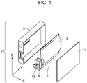
- FIG. 1 is a schematic diagram of an exemplary liquid container according to an embodiment of the present disclosure.
- a liquid container 2 mainly includes a casing 6 and a pouch 5.
- the casing 6 contains the pouch 5 and can be covered with a cover 7 as illustrated in Fig. 1 .
- the pouch 5 mainly includes a liquid storing portion 3, which contains liquid.
- a spout 4 having a joint 13 is attached and connected to the liquid storing portion 3 of the pouch 5.
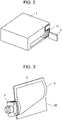
- Fig. 2 is a schematic diagram illustrating the liquid container 2 and a liquid discharge apparatus 1, onto which the liquid container 2 is mounted.
- the liquid discharge apparatus 1 includes a mounting portion 11, onto which the liquid container 2 is mounted.
- the liquid container 2 is inserted into the mounting portion 11, so that the liquid container 2 is mounted on the mounting portion 11.
- the liquid container 2 supplies the liquid to a liquid discharge head (not illustrated) of the liquid discharge apparatus through the joint 13.
- the mounting portion 11 is divided into individual compartments, which can respectively receive the liquid containers 2.
- Each of the liquid containers 2 can be removed from the mounting portion 11 when the liquid container 2 contains little or no liquid because the liquid is used up.
- the liquid container 2 is configured such that the casing 6 contains the pouch 5.
- the reason that the liquid container 2 has such a configuration will now be described.
- the pouch 5 is formed by a film. Examples of the film include a metallic film and a plastic film. If the pouch is formed by a plastic film, the plastic film for the pouch can be very thin, which indicates a very small amount of plastic used. In other words, such a pouch can contribute to less plastic usage or waste. However, it is difficult to stably mount the pouch 5 containing ink on the liquid discharge apparatus 1 because the pouch has low rigidity and is flexible. Therefore, the casing 6 having high rigidity is used, and the pouch 5 is contained in the casing 6.
- the film of the pouch 5 has a thickness of preferably from 0.1 to 1.0 mm.
- the casing 6 has a thickness of preferably 0.5 mm or more, more preferably from 1.0 to 5.0 mm.
- the pouch 5 is removable from the casing 6.
- the pouch 5 has the spout 4 attached thereto.
- the spout 4 is fitted into and attached to a receiving portion of the casing 6.
- the casing 6 is covered with the cover 7 and is then mounted on the liquid discharge apparatus 1.
- the above procedure is reversed: the casing 6 is pulled out of the liquid discharge apparatus 1, the cover 7 is removed, and the pouch 5 is removed from the casing 6.
- the pouch 5 is empty, a new pouch containing liquid is prepared and placed in the casing 6, from which the empty pouch has been removed. After that, as described above, the casing 6 is covered with the cover 7 as necessary.
- the casing 6 having high rigidity and made of, for example, plastic, is used.
- the casing 6 continues to be used, whereas the pouch 5 in the casing is replaceable.
- the casing 6 is made of plastic, the casing 6 essentially continues to be used and thus can contribute to less plastic waste. If the pouch 5 is made of plastic, the amount of plastic used can be small. Replacement of such a part with a new one causes no significant increase in plastic waste. Furthermore, the casing 6 having sufficient rigidity enables the liquid container to be stably mounted on or removed from the liquid discharge apparatus 1.
- the spout 4 is attached to the pouch 5.
- the spout 4 is made of resin material, such as polypropylene or polyethylene, and is connected or welded to the liquid storing portion 3 of the pouch 5 by a weld from a thermal welding process.
- the spout 4 can also have a size as small as possible in terms of less plastic usage.
- the Z direction refers to the direction of gravity (height) in a posture of the liquid container 2 that is taken when the liquid container 2 is mounted on the liquid discharge apparatus
- the Y direction refers to a direction orthogonal to the Z direction. In Fig.
- the Y direction is an insertion direction in which the liquid container is inserted into the liquid discharge apparatus, and corresponds to a longitudinal direction of the liquid container.
- the X direction refers to a direction orthogonal to the Y direction and the Z direction, and corresponds to a lateral or widthwise direction of the liquid container.
- the spout 4 has a dimension in the Z direction that is less than or equal to half that of the pouch.
- the spout 4 can have a size as small as possible in the Y direction.
- the spout 4 has a dimension in the Y direction that is less than or equal to half that of the pouch.
- the spout 4 can increase the ease of discharge of the liquid in the pouch 5.
- the spout 4 can be positioned such that the middle of the spout 4 in the Z direction is located at a level that is lower than 2/A in the direction of gravity, where A denotes the dimension of the pouch 5 in the Z direction.
- the liquid storing portion 3 constitutes most of the pouch 5.
- the liquid storing portion 3, which is formed by a film, can be regarded as a pouch.
- the liquid storing portion 3 is made of, for example, a metallic film, a plastic film, or a combination of these films.
- the liquid storing portion 3 can have a gas-barrier property or a light-shielding property to protect liquid contained therein.
- the liquid storing portion 3 can be formed by a single film or a laminate of films. Examples of the metallic film include an aluminum film. If the liquid storing portion 3 is thermally welded to the spout 4, part of the liquid storing portion 3 that is thermally welded can be made of resin.
- the liquid storing portion 3 can include an outer film made of aluminum and an inner film made of resin.
- the inner film can be thermally welded to the spout 4.
- the liquid storing portion 3 may be shaped like a three-sided seal bag, which is formed by welding peripheral parts of a film, or may be shaped like a standing pouch having a depth.
- the film forming the liquid storing portion 3 may be transparent or translucent so that the color of liquid contained in the liquid storing portion or the remaining amount thereof can be visually observed.
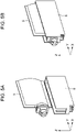
- Fig. 3 is a schematic diagram of the liquid storing portion 3 of the pouch 5 illustrating its exemplary configuration.
- the pouch 5 of Fig. 3 is a bag including a welded portion 12, subjected to welding, extending around the periphery of the liquid storing portion 3.
- a lower part of the welded portion 12 in the direction of gravity has an upper edge sloping downward in the direction of gravity toward the spout 4 from a side remote from the spout 4.
- Such a configuration enables the contained liquid to be readily guided to the spout 4, thus enhancing the efficiency of usage of the liquid.
- the casing 6 is made of a material having high rigidity.
- the casing 6 needs to be made of a material having a higher rigidity than at least a material for the pouch 5.
- the casing 6, which is used repeatedly as described above, can be made of plastic, such as polypropylene or polyethylene, or can be made of metal or carbon resin.
- the casing 6 having high rigidity facilitates mounting of the liquid container on the liquid discharge apparatus 1.
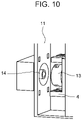
- Fig. 10 is a schematic enlarged view of part of the mounting portion 11 of the liquid discharge apparatus, and illustrates the liquid container as being mounted on the liquid discharge apparatus.
- the mounting portion 11 has a supply port 14, to which the joint 13 of the spout 4 is coupled.
- the casing 6 having high rigidity and capable of bearing a load helps mounting of the liquid container, thus enabling the joint 13 of the spout 4 joined to the pouch in the casing 6 to be readily coupled to the supply port 14.
- an insertion opening of the casing 6 containing the pouch can be covered with the cover 7.
- the casing 6 can have a box shape having six faces when covered with the cover 7.
- the casing 6 may have any other shape. For example, an insertion opening, through which the pouch is inserted, may remain open.
- the casing 6 may have a box shape having five faces with no cover for the insertion opening.
- the casing 6 may have a frame shape having four faces (or having two open faces).
- Fig. 4 illustrates two frame-shaped casings, in which different pouches are placed.
- the casing 6 may be shaped as illustrated in Figs. 5A and 5B .
- the casing 6 may have an opening, through which the pouch is inserted into the casing, located at an upper level in the direction of gravity.
- the casings of the liquid containers may have different shapes. All of the casings do not have to be made different in shape from each other. At least two casings are made different in shape from each other.
- the mounting portion 11 can include a structure for each of the liquid containers in each of regions where the liquid containers are held.
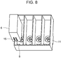
- Fig. 6 illustrates the mounting portion 11 including ribs 8. The ribs 8 for four liquid containers are different in shape (arrangement pattern).
- the casing 6 has a groove 15 corresponding to the ribs 8. In such a configuration, when the liquid container is mounted at a correct location, the ribs 8 are fitted in the groove 15, so that the liquid container is successfully mounted.
- FIGs. 7A and 7B illustrate relationships between the spouts 4 and the casings 6.
- the shape of the casing 6, particularly, the shape of the groove 15, in Fig. 7A differs from that in Fig. 7B .
- the structure of the spout 4 corresponding to the casing 6 in Fig. 7A also differs from that in Fig. 7B.
- Figs. 7A and 7B illustrate the correspondence between the structures of the spouts 4 and the structures of the casings 6. As long as the structure of the spout 4 matches the structure of the casing 6, the spout and the pouch can be attached to the casing 6, thus preventing mismatch between the spout and the casing.
- the casings 6 may have different shaped grooves 15 in lower portions, and the mounting portion 11 may include the ribs 8 corresponding to the respective grooves.
- the casings having the same shape may be used for the liquid containers to be mounted on the liquid discharge apparatus.
- each of the spouts of the liquid containers can include an incorrect-mounting preventing mechanism. If the casings slightly differ from each other due to a manufacturing error, the casings can be regarded as having the same shape.
- Fig. 9 illustrates the mounting portion 11 and the shapes of the liquid containers 2.
- the spouts 4 of the liquid containers 2 each include protrusions 10.
- the casings 6 of the liquid containers 2 have the same shape, whereas the protrusions 10 of the liquid containers 2 differ from each other.
- the protrusions of the spouts differ in number and size.
- the mounting portion 11 has recesses 16 around the supply ports 14. If the liquid container is mounted at a correct location, for example, if the liquid container containing cyan ink is mounted on a mounting section for cyan, the protrusions 10 can be fitted in the recesses 16, so that the liquid container can be successfully mounted. If the liquid container is mounted at an incorrect location, for example, if the liquid container containing magenta ink is mounted on the mounting section for cyan, the protrusions cannot be fitted in the recesses, so that the liquid container will fail to be mounted.
- the arrangement of the protrusions and the recesses for example, where the protrusions are arranged and where the recesses are arranged, is not limited to the above example.
- the protrusions and the recesses can be appropriately arranged so as to be suitable for the shape of, for example, the liquid discharge apparatus 1, the liquid container 2, or the spout 4.
- the fit between the mounting portion and the liquid container in any configuration is intended to prevent the liquid in the liquid container mounted at an incorrect location from accidentally entering the liquid discharge apparatus.
- the liquid container 2 can be prevented from being inserted into the mounting portion 11 before the joint 13 of the liquid container 2 comes into contact with the supply port 14 of the mounting portion 11. Therefore, as illustrated in Fig. 10 , the spout 4 can be projected farther than the joint 13 in the insertion direction, or the Y direction, for the fit between the liquid discharge apparatus 1 and the spout 4.
- the liquid discharge apparatus 1 If the liquid discharge apparatus 1 is activated to discharge liquid under conditions where the liquid container 2 is partially mounted on the mounting portion 11, air may enter a passage in the liquid discharge apparatus. After that, the liquid discharge apparatus may fail to discharge liquid accurately. To recover the liquid discharge apparatus from such a state, for example, a large amount of liquid may be discharged to remove the air in the passage. Disadvantageously, the large amount of liquid may be wasted.
- a board can be incorporated in the casing 6 or the spout 4 and be effectively used. The board incorporated in the spout 4 can be brought into electrical communication with, for example, an electrode on the liquid discharge apparatus 1 when the liquid container 2 is fully mounted on the mounting portion 11 of the liquid discharge apparatus 1. As long as the liquid discharge apparatus 1 is allowed to discharge the liquid upon determination of the electrical communication, the above-described disadvantage can be addressed.
- the liquid container is inserted into the liquid discharge apparatus in the Y direction, which is illustrated in Figs. 1 , 5A, and 5B , in the examples illustrated in Figs. 2 and 6 .
- the pouch 5 can be inserted into the casing 6 in the X direction or the Z direction.
- Figs. 5A and 5B illustrate the configuration in which the pouch 5 is inserted into the casing 6 in the Z direction.
- the pouch 5 can be fixed in the Y direction when placed in the casing 6.
- the spout 4 can be positioned at a lower level in the direction of gravity.
- the spout 4 may be positioned at the bottom of the pouch 5 located at a lower level in the direction of gravity.
- the liquid container is inserted into the liquid discharge apparatus in the Z direction. Therefore, the displacement of the spout 4 relative to the casing 6 in the Z direction can be minimized.
- the pouch 5 can be inserted into the casing 6 in the X direction or the Y direction.
- the pouch 5 can be fixed in the Z direction when placed in the casing 6.
- a liquid container (2) to be mounted on a liquid discharge apparatus includes a casing (6), a pouch (5), and a spout (4).
- the pouch is removable and contained in the casing.
- the spout is connected to the pouch.
- the casing has a rigidity that is higher than a rigidity of the pouch.
- the pouch and the spout each have a dimension in a direction of gravity in a posture of the liquid container that is taken when the liquid container is mounted on the liquid discharge apparatus, and the dimension of the spout is less than or equal to half the dimension of the pouch.
Landscapes
- Ink Jet (AREA)
- Packages (AREA)
Abstract
Description
- The present disclosure relates to liquid containers.
- Some liquid discharge apparatuses, such as inkjet printers, incorporate a removable liquid container that stores liquid, such as ink. The liquid container mounted on such a liquid discharge apparatus supplies the liquid to a liquid discharge head.
Japanese Patent No. 4380712 - A liquid container like that disclosed in
Japanese Patent No. 4380712 - An ink cartridge that has supplied all of ink contained therein to an inkjet printer is replaced by a new ink cartridge. The spent ink cartridge may be collected and reused or may be discarded without being collected.
- As the impact of plastic waste on marine life has recently been pointed out, the amount of plastic waste is required to be minimized. A liquid container that contains liquid, such as ink, needs to be rigid to some extent to prevent leakage of the liquid or so that the liquid container can be readily mounted on a liquid discharge apparatus. A reduction in the amount of plastic used to form the liquid container tends to reduce the rigidity of the liquid container.
- The present disclosure in its first aspect provides a liquid container as specified in
claims 1 to 8. - Further features of the present disclosure will become apparent from the following description of exemplary embodiments with reference to the attached drawings.
-
-
Fig. 1 is a schematic diagram of a liquid container. -
Fig. 2 is a schematic diagram of a liquid discharge apparatus. -
Fig. 3 is a schematic diagram of a pouch of the liquid container illustrating its exemplary configuration. -
Fig. 4 is a schematic diagram of casings of the liquid containers. -
Figs. 5A and 5B are schematic diagrams illustrating the casing and the pouch of the liquid container. -
Fig. 6 is a schematic view of the liquid container illustrated as being mounted on a mounting portion. -
Figs. 7A and 7B are schematic diagrams illustrating the casings and spouts of the liquid containers. -
Fig. 8 is a schematic view of the liquid container illustrated as being mounted on the mounting portion. -
Fig. 9 is a schematic diagram illustrating the mounting portion and the liquid containers. -
Fig. 10 is a schematic view of the liquid container illustrated as being mounted on the mounting portion. - Embodiments of the present disclosure will be described below with reference to the drawings.
-
Fig. 1 is a schematic diagram of an exemplary liquid container according to an embodiment of the present disclosure. Aliquid container 2 mainly includes acasing 6 and apouch 5. Thecasing 6 contains thepouch 5 and can be covered with a cover 7 as illustrated inFig. 1 . Thepouch 5 mainly includes a liquid storingportion 3, which contains liquid. Aspout 4 having ajoint 13 is attached and connected to the liquid storingportion 3 of thepouch 5. -
Fig. 2 is a schematic diagram illustrating theliquid container 2 and aliquid discharge apparatus 1, onto which theliquid container 2 is mounted. Theliquid discharge apparatus 1 includes amounting portion 11, onto which theliquid container 2 is mounted. Theliquid container 2 is inserted into themounting portion 11, so that theliquid container 2 is mounted on themounting portion 11. After mounted, theliquid container 2 supplies the liquid to a liquid discharge head (not illustrated) of the liquid discharge apparatus through thejoint 13. Themounting portion 11 is divided into individual compartments, which can respectively receive theliquid containers 2. Each of theliquid containers 2 can be removed from themounting portion 11 when theliquid container 2 contains little or no liquid because the liquid is used up. - As described above, the
liquid container 2 is configured such that thecasing 6 contains thepouch 5. The reason that theliquid container 2 has such a configuration will now be described. Thepouch 5 is formed by a film. Examples of the film include a metallic film and a plastic film. If the pouch is formed by a plastic film, the plastic film for the pouch can be very thin, which indicates a very small amount of plastic used. In other words, such a pouch can contribute to less plastic usage or waste. However, it is difficult to stably mount thepouch 5 containing ink on theliquid discharge apparatus 1 because the pouch has low rigidity and is flexible. Therefore, thecasing 6 having high rigidity is used, and thepouch 5 is contained in thecasing 6. The film of thepouch 5 has a thickness of preferably from 0.1 to 1.0 mm. Thecasing 6 has a thickness of preferably 0.5 mm or more, more preferably from 1.0 to 5.0 mm. - More specifically, the
pouch 5 is removable from thecasing 6. Thepouch 5 has thespout 4 attached thereto. Thespout 4 is fitted into and attached to a receiving portion of thecasing 6. Thecasing 6 is covered with the cover 7 and is then mounted on theliquid discharge apparatus 1. - To remove the
pouch 5, the above procedure is reversed: thecasing 6 is pulled out of theliquid discharge apparatus 1, the cover 7 is removed, and thepouch 5 is removed from thecasing 6. When thepouch 5 is empty, a new pouch containing liquid is prepared and placed in thecasing 6, from which the empty pouch has been removed. After that, as described above, thecasing 6 is covered with the cover 7 as necessary. - According to the embodiment of the present disclosure, the
casing 6 having high rigidity and made of, for example, plastic, is used. Thecasing 6 continues to be used, whereas thepouch 5 in the casing is replaceable. - Although the
casing 6 is made of plastic, thecasing 6 essentially continues to be used and thus can contribute to less plastic waste. If thepouch 5 is made of plastic, the amount of plastic used can be small. Replacement of such a part with a new one causes no significant increase in plastic waste. Furthermore, thecasing 6 having sufficient rigidity enables the liquid container to be stably mounted on or removed from theliquid discharge apparatus 1. - The configuration of the
liquid container 2 will now be described in more detail. Thespout 4 is attached to thepouch 5. Thespout 4 is made of resin material, such as polypropylene or polyethylene, and is connected or welded to theliquid storing portion 3 of thepouch 5 by a weld from a thermal welding process. Thespout 4 can also have a size as small as possible in terms of less plastic usage. As used herein, the Z direction refers to the direction of gravity (height) in a posture of theliquid container 2 that is taken when theliquid container 2 is mounted on the liquid discharge apparatus, and the Y direction refers to a direction orthogonal to the Z direction. InFig. 1 , the Y direction is an insertion direction in which the liquid container is inserted into the liquid discharge apparatus, and corresponds to a longitudinal direction of the liquid container. As used herein, the X direction refers to a direction orthogonal to the Y direction and the Z direction, and corresponds to a lateral or widthwise direction of the liquid container. - The
spout 4 has a dimension in the Z direction that is less than or equal to half that of the pouch. Thespout 4 can have a size as small as possible in the Y direction. Thespout 4 has a dimension in the Y direction that is less than or equal to half that of the pouch. - At a lower level in the direction of gravity, the
spout 4 can increase the ease of discharge of the liquid in thepouch 5. Specifically, thespout 4 can be positioned such that the middle of thespout 4 in the Z direction is located at a level that is lower than 2/A in the direction of gravity, where A denotes the dimension of thepouch 5 in the Z direction. - The
liquid storing portion 3 constitutes most of thepouch 5. Theliquid storing portion 3, which is formed by a film, can be regarded as a pouch. Theliquid storing portion 3 is made of, for example, a metallic film, a plastic film, or a combination of these films. Theliquid storing portion 3 can have a gas-barrier property or a light-shielding property to protect liquid contained therein. Theliquid storing portion 3 can be formed by a single film or a laminate of films. Examples of the metallic film include an aluminum film. If theliquid storing portion 3 is thermally welded to thespout 4, part of theliquid storing portion 3 that is thermally welded can be made of resin. For example, theliquid storing portion 3 can include an outer film made of aluminum and an inner film made of resin. The inner film can be thermally welded to thespout 4. Theliquid storing portion 3 may be shaped like a three-sided seal bag, which is formed by welding peripheral parts of a film, or may be shaped like a standing pouch having a depth. The film forming theliquid storing portion 3 may be transparent or translucent so that the color of liquid contained in the liquid storing portion or the remaining amount thereof can be visually observed. -
Fig. 3 is a schematic diagram of theliquid storing portion 3 of thepouch 5 illustrating its exemplary configuration. Thepouch 5 ofFig. 3 is a bag including a weldedportion 12, subjected to welding, extending around the periphery of theliquid storing portion 3. A lower part of the weldedportion 12 in the direction of gravity has an upper edge sloping downward in the direction of gravity toward thespout 4 from a side remote from thespout 4. Such a configuration enables the contained liquid to be readily guided to thespout 4, thus enhancing the efficiency of usage of the liquid. - The
casing 6 will now be described. Thecasing 6 is made of a material having high rigidity. Thecasing 6 needs to be made of a material having a higher rigidity than at least a material for thepouch 5. Thecasing 6, which is used repeatedly as described above, can be made of plastic, such as polypropylene or polyethylene, or can be made of metal or carbon resin. Thecasing 6 having high rigidity facilitates mounting of the liquid container on theliquid discharge apparatus 1.Fig. 10 is a schematic enlarged view of part of the mountingportion 11 of the liquid discharge apparatus, and illustrates the liquid container as being mounted on the liquid discharge apparatus. The mountingportion 11 has asupply port 14, to which the joint 13 of thespout 4 is coupled. If the liquid container included only the pouch, it would be difficult to couple the joint 13 to thesupply port 14 with a sufficient force because the container had low rigidity. Consequently, the liquid might fail to be successfully supplied. For this reason, thecasing 6 having high rigidity and capable of bearing a load helps mounting of the liquid container, thus enabling the joint 13 of thespout 4 joined to the pouch in thecasing 6 to be readily coupled to thesupply port 14. - As illustrated in
Fig. 1 , after the pouch is inserted into and placed in thecasing 6, an insertion opening of thecasing 6 containing the pouch can be covered with the cover 7. Thecasing 6 can have a box shape having six faces when covered with the cover 7. Thecasing 6 may have any other shape. For example, an insertion opening, through which the pouch is inserted, may remain open. Thecasing 6 may have a box shape having five faces with no cover for the insertion opening. As illustrated inFig. 4 , thecasing 6 may have a frame shape having four faces (or having two open faces).Fig. 4 illustrates two frame-shaped casings, in which different pouches are placed. When each of the pouches is placed in the corresponding one of the frame-shaped casings, opposite side faces of the pouch are exposed through respective openings of the casing. Furthermore, thecasing 6 may be shaped as illustrated inFigs. 5A and 5B . Thecasing 6 may have an opening, through which the pouch is inserted into the casing, located at an upper level in the direction of gravity. - In a case where multiple liquid containers are mounted on the liquid discharge apparatus, the casings of the liquid containers may have different shapes. All of the casings do not have to be made different in shape from each other. At least two casings are made different in shape from each other. In this case, the mounting
portion 11 can include a structure for each of the liquid containers in each of regions where the liquid containers are held.Fig. 6 illustrates the mountingportion 11 includingribs 8. Theribs 8 for four liquid containers are different in shape (arrangement pattern). Thecasing 6 has agroove 15 corresponding to theribs 8. In such a configuration, when the liquid container is mounted at a correct location, theribs 8 are fitted in thegroove 15, so that the liquid container is successfully mounted. If the liquid container is mounted at an incorrect location, theribs 8 will fail to be fitted in thegroove 15, thus preventing incorrect mounting.Figs. 7A and 7B illustrate relationships between thespouts 4 and thecasings 6. The shape of thecasing 6, particularly, the shape of thegroove 15, inFig. 7A differs from that inFig. 7B . The structure of thespout 4 corresponding to thecasing 6 inFig. 7A also differs from that inFig. 7B. Figs. 7A and 7B illustrate the correspondence between the structures of thespouts 4 and the structures of thecasings 6. As long as the structure of thespout 4 matches the structure of thecasing 6, the spout and the pouch can be attached to thecasing 6, thus preventing mismatch between the spout and the casing. - If different shaped casings are used for the liquid containers, as illustrated in
Fig. 8 , thecasings 6 may have different shapedgrooves 15 in lower portions, and the mountingportion 11 may include theribs 8 corresponding to the respective grooves. - Considering the productivity of the casings, the casings having the same shape may be used for the liquid containers to be mounted on the liquid discharge apparatus. In this case, each of the spouts of the liquid containers can include an incorrect-mounting preventing mechanism. If the casings slightly differ from each other due to a manufacturing error, the casings can be regarded as having the same shape.
Fig. 9 illustrates the mountingportion 11 and the shapes of theliquid containers 2. Thespouts 4 of theliquid containers 2 each includeprotrusions 10. Thecasings 6 of theliquid containers 2 have the same shape, whereas theprotrusions 10 of theliquid containers 2 differ from each other. InFig. 9 , the protrusions of the spouts differ in number and size. The mountingportion 11 hasrecesses 16 around thesupply ports 14. If the liquid container is mounted at a correct location, for example, if the liquid container containing cyan ink is mounted on a mounting section for cyan, theprotrusions 10 can be fitted in therecesses 16, so that the liquid container can be successfully mounted. If the liquid container is mounted at an incorrect location, for example, if the liquid container containing magenta ink is mounted on the mounting section for cyan, the protrusions cannot be fitted in the recesses, so that the liquid container will fail to be mounted. - For the fit between the protrusions and the recesses, the arrangement of the protrusions and the recesses, for example, where the protrusions are arranged and where the recesses are arranged, is not limited to the above example. The protrusions and the recesses can be appropriately arranged so as to be suitable for the shape of, for example, the
liquid discharge apparatus 1, theliquid container 2, or thespout 4. - The fit between the mounting portion and the liquid container in any configuration is intended to prevent the liquid in the liquid container mounted at an incorrect location from accidentally entering the liquid discharge apparatus. To avoid such an accident, the
liquid container 2 can be prevented from being inserted into the mountingportion 11 before the joint 13 of theliquid container 2 comes into contact with thesupply port 14 of the mountingportion 11. Therefore, as illustrated inFig. 10 , thespout 4 can be projected farther than the joint 13 in the insertion direction, or the Y direction, for the fit between theliquid discharge apparatus 1 and thespout 4. - If the
liquid discharge apparatus 1 is activated to discharge liquid under conditions where theliquid container 2 is partially mounted on the mountingportion 11, air may enter a passage in the liquid discharge apparatus. After that, the liquid discharge apparatus may fail to discharge liquid accurately. To recover the liquid discharge apparatus from such a state, for example, a large amount of liquid may be discharged to remove the air in the passage. Disadvantageously, the large amount of liquid may be wasted. To determine whether thecasing 6 is fully mounted on theliquid discharge apparatus 1, a board can be incorporated in thecasing 6 or thespout 4 and be effectively used. The board incorporated in thespout 4 can be brought into electrical communication with, for example, an electrode on theliquid discharge apparatus 1 when theliquid container 2 is fully mounted on the mountingportion 11 of theliquid discharge apparatus 1. As long as theliquid discharge apparatus 1 is allowed to discharge the liquid upon determination of the electrical communication, the above-described disadvantage can be addressed. - To mount the liquid container on the liquid discharge apparatus, the liquid container is inserted into the liquid discharge apparatus in the Y direction, which is illustrated in
Figs. 1 ,5A, and 5B , in the examples illustrated inFigs. 2 and6 . For this reason, displacement of thespout 4 relative to thecasing 6 in the Y direction can be minimized in the liquid container. Therefore, thepouch 5 can be inserted into thecasing 6 in the X direction or the Z direction. For example,Figs. 5A and 5B illustrate the configuration in which thepouch 5 is inserted into thecasing 6 in the Z direction. Furthermore, thepouch 5 can be fixed in the Y direction when placed in thecasing 6. - As described above, the
spout 4 can be positioned at a lower level in the direction of gravity. Thespout 4 may be positioned at the bottom of thepouch 5 located at a lower level in the direction of gravity. In this case, the liquid container is inserted into the liquid discharge apparatus in the Z direction. Therefore, the displacement of thespout 4 relative to thecasing 6 in the Z direction can be minimized. For example, thepouch 5 can be inserted into thecasing 6 in the X direction or the Y direction. Furthermore, thepouch 5 can be fixed in the Z direction when placed in thecasing 6. - While the present disclosure has been described with reference to exemplary embodiments, it is to be understood that the disclosure is not limited to the disclosed exemplary embodiments. The scope of the following claims is to be accorded the broadest interpretation so as to encompass all such modifications and equivalent structures and functions.
- A liquid container (2) to be mounted on a liquid discharge apparatus includes a casing (6), a pouch (5), and a spout (4). The pouch is removable and contained in the casing. The spout is connected to the pouch. The casing has a rigidity that is higher than a rigidity of the pouch. The pouch and the spout each have a dimension in a direction of gravity in a posture of the liquid container that is taken when the liquid container is mounted on the liquid discharge apparatus, and the dimension of the spout is less than or equal to half the dimension of the pouch.
Claims (8)
- A liquid container (2) to be mounted on a liquid discharge apparatus, the liquid container comprising:a casing (6);a pouch (5) that is removable and contained in the casing; anda spout (4) connected to the pouch,wherein the casing has a rigidity that is higher than a rigidity of the pouch, andwherein the pouch and the spout each have a dimension in a direction of gravity in a posture of the liquid container that is taken when the liquid container is mounted on the liquid discharge apparatus, and the dimension of the spout is less than or equal to half the dimension of the pouch.
- The liquid container according to Claim 1, wherein the pouch includes a metallic film.
- The liquid container according to Claim 2, wherein the metallic film is aluminum.
- The liquid container according to any one of Claims 1 to 3, wherein the spout is connected to the pouch by a weld from a thermal welding process.
- The liquid container according to any one of Claims 1 to 4, wherein the casing includes plastic.
- The liquid container according to any one of Claims 1 to 5, wherein the casing includes a lid (7) to cover an opening of the casing containing the pouch, and has a box shape having six faces.
- The liquid container according to any one of Claims 1 to 5, wherein the casing has a frame shape having four faces, and opposite side faces of the pouch contained in the casing are exposed through openings of the casing.
- The liquid container according to any one of Claims 1 to 7, wherein the spout is positioned such that a middle of the spout in the direction of gravity is located at a level that is lower than 2/A in the direction of gravity, where A denotes the dimension of the pouch in the direction of gravity in the posture of the liquid container taken when the liquid container is mounted on the liquid discharge apparatus.
Applications Claiming Priority (1)
| Application Number | Priority Date | Filing Date | Title |
|---|---|---|---|
| JP2021058383A JP7665377B2 (en) | 2021-03-30 | 2021-03-30 | Liquid storage container |
Publications (1)
| Publication Number | Publication Date |
|---|---|
| EP4067091A1 true EP4067091A1 (en) | 2022-10-05 |
Family
ID=80683132
Family Applications (1)
| Application Number | Title | Priority Date | Filing Date |
|---|---|---|---|
| EP22160393.9A Pending EP4067091A1 (en) | 2021-03-30 | 2022-03-07 | Liquid container |
Country Status (5)
| Country | Link |
|---|---|
| US (2) | US12064974B2 (en) |
| EP (1) | EP4067091A1 (en) |
| JP (1) | JP7665377B2 (en) |
| KR (1) | KR20220136207A (en) |
| CN (1) | CN115139655B (en) |
Families Citing this family (2)
| Publication number | Priority date | Publication date | Assignee | Title |
|---|---|---|---|---|
| WO2024085613A1 (en) | 2022-10-21 | 2024-04-25 | 주식회사 엘지에너지솔루션 | Electrode assembly and electrochemical element comprising same |
| CN120152855A (en) * | 2022-11-07 | 2025-06-13 | 伟迪捷科技公司 | Housing for printer cartridge and method of manufacturing |
Citations (9)
| Publication number | Priority date | Publication date | Assignee | Title |
|---|---|---|---|---|
| EP1053874A2 (en) * | 1999-04-27 | 2000-11-22 | Canon Kabushiki Kaisha | Ink container, valve unit, ink container manufacturing method, ink jet head cartridge and recording apparatus |
| EP1088666A1 (en) * | 1999-09-29 | 2001-04-04 | Owens-Illinois Closure Inc., | Liquid containment and dispensing device |
| US20040012660A1 (en) * | 2002-07-18 | 2004-01-22 | Eastman Kodak Company | Ink cartridge having connectable-disconnectable housing and ink supply bag |
| US20060139420A1 (en) * | 2002-12-06 | 2006-06-29 | Masakazu Muranaka | Ink cartridge, housing therefor, ink bag, ink-jet recording apparatus, ink container, and image-forming apparatus |
| EP1749662A2 (en) * | 2005-08-04 | 2007-02-07 | Seiko Epson Corporation | Liquid container, and ink cartridge and ink jet printer having the same |
| JP4380712B2 (en) | 2007-02-28 | 2009-12-09 | ブラザー工業株式会社 | Droplet discharge device |
| EP2204288A1 (en) * | 2009-01-06 | 2010-07-07 | Ricoh Company, Ltd. | Ink cartridge and image forming apparatus employing the ink cartridge |
| EP2292431A1 (en) * | 2009-09-04 | 2011-03-09 | Ricoh Company, Ltd. | Liquid container, methods of assembling or disassembling liquid container, and image forming apparatus |
| EP2778203A1 (en) * | 2013-03-13 | 2014-09-17 | Ricoh Company, Ltd. | Ink for inkjet, ink cartridge using the ink, inkjet recorder and ink recorded matter |
Family Cites Families (25)
| Publication number | Priority date | Publication date | Assignee | Title |
|---|---|---|---|---|
| JPH0698774B2 (en) * | 1984-02-09 | 1994-12-07 | キヤノン株式会社 | Ink container |
| US6142617A (en) * | 1995-04-27 | 2000-11-07 | Hewlett-Packard Company | Ink container configured for use with compact supply station |
| CN101386230B (en) * | 2000-01-21 | 2011-04-13 | 精工爱普生株式会社 | Ink cartridge, and ink-jet recording apparatus using the same |
| EP1120258B1 (en) * | 2000-01-21 | 2006-05-17 | Seiko Epson Corporation | Ink cartridge, and ink-jet recording apparatus using the same |
| JP4390978B2 (en) | 2000-06-20 | 2009-12-24 | 大日本印刷株式会社 | Bag in carton |
| WO2003041963A1 (en) * | 2001-11-12 | 2003-05-22 | Seiko Epson Corporation | Ink cartridge |
| JP3891150B2 (en) * | 2002-07-09 | 2007-03-14 | セイコーエプソン株式会社 | Liquid cartridge and liquid container |
| US7093710B2 (en) * | 2002-10-31 | 2006-08-22 | Brother Kogyo Kabushiki Kaisha | Ink-package assembly, and method of producing the same |
| JP4193719B2 (en) * | 2003-03-05 | 2008-12-10 | セイコーエプソン株式会社 | Liquid container, liquid ejecting apparatus, and liquid container case |
| JP2004306505A (en) * | 2003-04-09 | 2004-11-04 | Brother Ind Ltd | Ink package |
| US7452062B2 (en) * | 2003-07-18 | 2008-11-18 | Seiko Epson Corporation | Liquid container with structure for controlling leaked liquid |
| US7384133B2 (en) * | 2003-08-08 | 2008-06-10 | Seiko Epson Corporation | Liquid container capable of maintaining airtightness |
| WO2006046464A1 (en) * | 2004-10-29 | 2006-05-04 | Konica Minolta Medical & Graphic, Inc. | Ultraviolet curable ink package |
| JP2006281794A (en) | 2006-07-24 | 2006-10-19 | Seiko Epson Corp | Printing whose characteristics can be changed by selecting the cartridge |
| JP5495942B2 (en) * | 2010-05-21 | 2014-05-21 | キヤノン株式会社 | Ink tank and printer |
| JP2012210730A (en) * | 2011-03-30 | 2012-11-01 | Brother Industries Ltd | ink cartridge |
| JP2013006350A (en) | 2011-06-24 | 2013-01-10 | Brother Industries Ltd | Ink cartridge |
| US9440755B2 (en) * | 2012-01-13 | 2016-09-13 | Seiko Epson Corporation | Liquid container and liquid consumption apparatus |
| JP2014213567A (en) * | 2013-04-26 | 2014-11-17 | 京セラドキュメントソリューションズ株式会社 | Liquid storage container and ink jet type image formation device |
| JP6269351B2 (en) * | 2014-06-30 | 2018-01-31 | 京セラドキュメントソリューションズ株式会社 | Ink container and ink jet recording apparatus including the same |
| JP6341120B2 (en) * | 2015-03-09 | 2018-06-13 | 京セラドキュメントソリューションズ株式会社 | Ink container and ink jet image forming apparatus |
| JP6661462B2 (en) | 2016-05-16 | 2020-03-11 | キヤノン株式会社 | Liquid ejection device and liquid supply container |
| CN107718891B (en) * | 2016-08-12 | 2021-04-27 | 精工爱普生株式会社 | liquid container |
| WO2020013852A1 (en) | 2018-07-13 | 2020-01-16 | Hewlett-Packard Development Company, L.P. | Pliable print liquid supply reservoirs with offset spout |
| JP7247695B2 (en) * | 2019-03-26 | 2023-03-29 | セイコーエプソン株式会社 | Liquid storage container and liquid discharge system |
-
2021
- 2021-03-30 JP JP2021058383A patent/JP7665377B2/en active Active
-
2022
- 2022-03-07 EP EP22160393.9A patent/EP4067091A1/en active Pending
- 2022-03-09 US US17/690,558 patent/US12064974B2/en active Active
- 2022-03-28 KR KR1020220038242A patent/KR20220136207A/en active Pending
- 2022-03-28 CN CN202210310551.2A patent/CN115139655B/en active Active
-
2024
- 2024-07-25 US US18/784,061 patent/US12521993B2/en active Active
Patent Citations (9)
| Publication number | Priority date | Publication date | Assignee | Title |
|---|---|---|---|---|
| EP1053874A2 (en) * | 1999-04-27 | 2000-11-22 | Canon Kabushiki Kaisha | Ink container, valve unit, ink container manufacturing method, ink jet head cartridge and recording apparatus |
| EP1088666A1 (en) * | 1999-09-29 | 2001-04-04 | Owens-Illinois Closure Inc., | Liquid containment and dispensing device |
| US20040012660A1 (en) * | 2002-07-18 | 2004-01-22 | Eastman Kodak Company | Ink cartridge having connectable-disconnectable housing and ink supply bag |
| US20060139420A1 (en) * | 2002-12-06 | 2006-06-29 | Masakazu Muranaka | Ink cartridge, housing therefor, ink bag, ink-jet recording apparatus, ink container, and image-forming apparatus |
| EP1749662A2 (en) * | 2005-08-04 | 2007-02-07 | Seiko Epson Corporation | Liquid container, and ink cartridge and ink jet printer having the same |
| JP4380712B2 (en) | 2007-02-28 | 2009-12-09 | ブラザー工業株式会社 | Droplet discharge device |
| EP2204288A1 (en) * | 2009-01-06 | 2010-07-07 | Ricoh Company, Ltd. | Ink cartridge and image forming apparatus employing the ink cartridge |
| EP2292431A1 (en) * | 2009-09-04 | 2011-03-09 | Ricoh Company, Ltd. | Liquid container, methods of assembling or disassembling liquid container, and image forming apparatus |
| EP2778203A1 (en) * | 2013-03-13 | 2014-09-17 | Ricoh Company, Ltd. | Ink for inkjet, ink cartridge using the ink, inkjet recorder and ink recorded matter |
Also Published As
| Publication number | Publication date |
|---|---|
| CN115139655B (en) | 2026-03-27 |
| JP2022155053A (en) | 2022-10-13 |
| JP7665377B2 (en) | 2025-04-21 |
| US20220314632A1 (en) | 2022-10-06 |
| CN115139655A (en) | 2022-10-04 |
| KR20220136207A (en) | 2022-10-07 |
| US12521993B2 (en) | 2026-01-13 |
| US12064974B2 (en) | 2024-08-20 |
| US20240375404A1 (en) | 2024-11-14 |
Similar Documents
| Publication | Publication Date | Title |
|---|---|---|
| US12521993B2 (en) | Liquid container | |
| US7377627B2 (en) | Ink cartridge, housing therefor, ink bag, ink-jet recording apparatus, ink container, and image-forming apparatus | |
| KR100249867B1 (en) | Ink container, ink container holder for removably holding ink container, and ink container cap | |
| TWI337944B (en) | ||
| US8534806B2 (en) | Installing fluid container in fluid ejection device | |
| NZ280044A (en) | Multi-chambered ink cartridge for ink jet printer | |
| EP1844938A2 (en) | Liquid container | |
| JP6111748B2 (en) | Liquid container container, liquid supply device, and liquid ejection device | |
| JP4655503B2 (en) | Liquid container | |
| EP1905595B1 (en) | Ink cartridge for computer printer | |
| EP1219445A1 (en) | Ink cartridge | |
| JP6402642B2 (en) | Liquid container | |
| CN104786662A (en) | Liquid ejecting system, liquid ejecting apparatus, and containing unit | |
| CN114475002A (en) | Ink replenishing container | |
| US20160136961A1 (en) | Ink Cartridge and Printer | |
| EP0756937B1 (en) | Connecting structure for printing head and ink cartridge | |
| JP2021024274A (en) | Liquid recovery apparatus and liquid recovery filling system | |
| EP4647258A1 (en) | Ink storage bag and method for manufacturing ink storage bag | |
| JP2001018415A (en) | ink cartridge | |
| JP2024006596A (en) | Liquid storage body | |
| JP6222331B2 (en) | Liquid ejector | |
| US7416289B2 (en) | Ink cartridge and inkjet recording apparatus equipped with the ink cartridge | |
| KR20100082810A (en) | The ink cartridge that it is easy to fill ink | |
| JP2017105102A (en) | Liquid storage container and liquid storage structure | |
| CN113135042A (en) | Liquid ejecting apparatus |
Legal Events
| Date | Code | Title | Description |
|---|---|---|---|
| PUAI | Public reference made under article 153(3) epc to a published international application that has entered the european phase |
Free format text: ORIGINAL CODE: 0009012 |
|
| STAA | Information on the status of an ep patent application or granted ep patent |
Free format text: STATUS: THE APPLICATION HAS BEEN PUBLISHED |
|
| AK | Designated contracting states |
Kind code of ref document: A1 Designated state(s): AL AT BE BG CH CY CZ DE DK EE ES FI FR GB GR HR HU IE IS IT LI LT LU LV MC MK MT NL NO PL PT RO RS SE SI SK SM TR |
|
| STAA | Information on the status of an ep patent application or granted ep patent |
Free format text: STATUS: REQUEST FOR EXAMINATION WAS MADE |
|
| 17P | Request for examination filed |
Effective date: 20230405 |
|
| RBV | Designated contracting states (corrected) |
Designated state(s): AL AT BE BG CH CY CZ DE DK EE ES FI FR GB GR HR HU IE IS IT LI LT LU LV MC MK MT NL NO PL PT RO RS SE SI SK SM TR |
|
| STAA | Information on the status of an ep patent application or granted ep patent |
Free format text: STATUS: EXAMINATION IS IN PROGRESS |
|
| 17Q | First examination report despatched |
Effective date: 20240625 |