EP4066950A1 - Two-axis depowdering - Google Patents
Two-axis depowdering Download PDFInfo
- Publication number
- EP4066950A1 EP4066950A1 EP22166031.9A EP22166031A EP4066950A1 EP 4066950 A1 EP4066950 A1 EP 4066950A1 EP 22166031 A EP22166031 A EP 22166031A EP 4066950 A1 EP4066950 A1 EP 4066950A1
- Authority
- EP
- European Patent Office
- Prior art keywords
- plate
- mounting plate
- ultrasonic transducer
- recited
- deflection
- Prior art date
- Legal status (The legal status is an assumption and is not a legal conclusion. Google has not performed a legal analysis and makes no representation as to the accuracy of the status listed.)
- Granted
Links
Images


Classifications
-
- B—PERFORMING OPERATIONS; TRANSPORTING
- B08—CLEANING
- B08B—CLEANING IN GENERAL; PREVENTION OF FOULING IN GENERAL
- B08B7/00—Cleaning by methods not provided for in a single other subclass or a single group in this subclass
- B08B7/02—Cleaning by methods not provided for in a single other subclass or a single group in this subclass by distortion, beating, or vibration of the surface to be cleaned
-
- B—PERFORMING OPERATIONS; TRANSPORTING
- B29—WORKING OF PLASTICS; WORKING OF SUBSTANCES IN A PLASTIC STATE IN GENERAL
- B29C—SHAPING OR JOINING OF PLASTICS; SHAPING OF MATERIAL IN A PLASTIC STATE, NOT OTHERWISE PROVIDED FOR; AFTER-TREATMENT OF THE SHAPED PRODUCTS, e.g. REPAIRING
- B29C64/00—Additive manufacturing, i.e. manufacturing of three-dimensional [3D] objects by additive deposition, additive agglomeration or additive layering, e.g. by 3D printing, stereolithography or selective laser sintering
- B29C64/30—Auxiliary operations or equipment
- B29C64/35—Cleaning
-
- B—PERFORMING OPERATIONS; TRANSPORTING
- B08—CLEANING
- B08B—CLEANING IN GENERAL; PREVENTION OF FOULING IN GENERAL
- B08B13/00—Accessories or details of general applicability for machines or apparatus for cleaning
-
- B—PERFORMING OPERATIONS; TRANSPORTING
- B08—CLEANING
- B08B—CLEANING IN GENERAL; PREVENTION OF FOULING IN GENERAL
- B08B7/00—Cleaning by methods not provided for in a single other subclass or a single group in this subclass
- B08B7/02—Cleaning by methods not provided for in a single other subclass or a single group in this subclass by distortion, beating, or vibration of the surface to be cleaned
- B08B7/026—Using sound waves
- B08B7/028—Using ultrasounds
-
- B—PERFORMING OPERATIONS; TRANSPORTING
- B22—CASTING; POWDER METALLURGY
- B22F—WORKING METALLIC POWDER; MANUFACTURE OF ARTICLES FROM METALLIC POWDER; MAKING METALLIC POWDER; APPARATUS OR DEVICES SPECIALLY ADAPTED FOR METALLIC POWDER
- B22F10/00—Additive manufacturing of workpieces or articles from metallic powder
- B22F10/60—Treatment of workpieces or articles after build-up
- B22F10/68—Cleaning or washing
-
- B—PERFORMING OPERATIONS; TRANSPORTING
- B33—ADDITIVE MANUFACTURING TECHNOLOGY
- B33Y—ADDITIVE MANUFACTURING, i.e. MANUFACTURING OF THREE-DIMENSIONAL [3D] OBJECTS BY ADDITIVE DEPOSITION, ADDITIVE AGGLOMERATION OR ADDITIVE LAYERING, e.g. BY 3D PRINTING, STEREOLITHOGRAPHY OR SELECTIVE LASER SINTERING
- B33Y30/00—Apparatus for additive manufacturing; Details thereof or accessories therefor
-
- B—PERFORMING OPERATIONS; TRANSPORTING
- B33—ADDITIVE MANUFACTURING TECHNOLOGY
- B33Y—ADDITIVE MANUFACTURING, i.e. MANUFACTURING OF THREE-DIMENSIONAL [3D] OBJECTS BY ADDITIVE DEPOSITION, ADDITIVE AGGLOMERATION OR ADDITIVE LAYERING, e.g. BY 3D PRINTING, STEREOLITHOGRAPHY OR SELECTIVE LASER SINTERING
- B33Y40/00—Auxiliary operations or equipment, e.g. for material handling
- B33Y40/20—Post-treatment, e.g. curing, coating or polishing
-
- B—PERFORMING OPERATIONS; TRANSPORTING
- B22—CASTING; POWDER METALLURGY
- B22F—WORKING METALLIC POWDER; MANUFACTURE OF ARTICLES FROM METALLIC POWDER; MAKING METALLIC POWDER; APPARATUS OR DEVICES SPECIALLY ADAPTED FOR METALLIC POWDER
- B22F2999/00—Aspects linked to processes or compositions used in powder metallurgy
-
- Y—GENERAL TAGGING OF NEW TECHNOLOGICAL DEVELOPMENTS; GENERAL TAGGING OF CROSS-SECTIONAL TECHNOLOGIES SPANNING OVER SEVERAL SECTIONS OF THE IPC; TECHNICAL SUBJECTS COVERED BY FORMER USPC CROSS-REFERENCE ART COLLECTIONS [XRACs] AND DIGESTS
- Y02—TECHNOLOGIES OR APPLICATIONS FOR MITIGATION OR ADAPTATION AGAINST CLIMATE CHANGE
- Y02P—CLIMATE CHANGE MITIGATION TECHNOLOGIES IN THE PRODUCTION OR PROCESSING OF GOODS
- Y02P10/00—Technologies related to metal processing
- Y02P10/25—Process efficiency
Definitions
- the present disclosure relates to additive manufacturing, and more particularly to powder removal from parts after additive manufacturing processes that use stock powder such as laser powder bed fusion (LPBF) and the like.
- stock powder such as laser powder bed fusion (LPBF) and the like.
- Depowdering LPBF parts is a rate limiting part of the additive manufacturing process.
- Traditional commercial products and solutions fall short when applied to intricate parts. It remains important to have multiple tool options for depowdering to suit more and more geometries. Some of the traditional tools are effective, but there is an ongoing need for improvement and diversity of tools for depowdering additive manufactured parts.
- a system for depowdering additively manufactured parts includes a deflection plate, a hammer device mounted to a first side of the deflection plate, and a mounting plate operatively connected to a second side of the deflection plate relative to the hammer device, the mounting plate being configured for rotation relative to the deflection plate.
- An ultrasonic transducer system can be mounted to the mounting plate for inducing ultrasonic vibrations into the mounting plate.
- the ultrasonic transducer system can include at least one ultrasonic transducer ring mount mounted to the mounting plate. Each ring mount can include a receptacle for mounting a respective ultrasonic transducer thereto.
- the ultrasonic transducers can be of an electrically insulative material and can be hardened against explosion for safe use with explosive powder.
- the at least one ultrasonic transducer ring mounts can be a pair of ultrasonic transducer ring mounts.
- a first ultrasonic transducer having a first frequency can be mounted to a first one of the ultrasonic transducer ring mounts, and a second ultrasonic transducer having a second frequency can be mounted to a second one of the ultrasonic transducer ring mounts.
- the first frequency of the first ultrasonic transducer can be different than the second frequency of the second ultrasonic transducer.
- An arm can connect between an arm actuator and the deflection plate such that the arm actuator is configured to rotate the arm and deflection plate through 350° of rotation back and forth about an arm axis defined along the arm.
- a plate actuator can be connected to the deflection plate and to the mounting plate for actuating rotation of the mounting plate relative to the deflection plate within a plane parallel to a plane defined by the second surface of the deflection plate.
- the plate actuator can be configured to rotate the mounting plate through 80° of rotation back and forth about a plate axis perpendicular to the second surface of the deflection plate.
- the mounting plate can include an inner hub and an outer rim connected to one another by a plurality of radial spokes.
- the rim of the mounting plate can include a plurality of sets of fastener holes configured to receive fasteners of a variety of different build plate configurations.
- the mounting plate can include a lip, wherein only the lip of the mounting plate contacts the deflection plate.
- a retention plate can be mounted to the deflection plate with a portion of the mounting plate between the deflection plate and retention plate.
- a controller can be operatively connected to control movement of the mounting plate, and actuation of the hammer device and transducer system.
- the controller can include machine-readable instructions configured to cause the controller to rotate a build plate fixed to the mounting plate through yaw, pitch, and roll angles and to remove powder while doing so by controlling the hammer device to vibrate the build plate.
- the machine-readable instructions can include instructions to rotate a two axis system of actuators to rotate the mounting plate through yaw, pitch, and roll.
- the controller can be connected to the ultrasonic transducer system such that the machine-readable instructions can include instructions to drive ultrasonic vibrations from the ultrasonic transducer system into the build plate.
- the machine readable instructions can include instructions to sweep the ultrasonic transducer system through a range of resonant frequencies.
- a build plate having an additively manufactured build can be mounted to the mounting plate with a plurality of fasteners.
- the fasteners can engage the mounting plate in part through a respective die spring for each fastener.
- FIG. 1 a partial view of an embodiment of a system in accordance with the disclosure is shown in Fig. 1 and is designated generally by reference character 100.
- FIGs. 2-3 Other embodiments of systems in accordance with the disclosure, or aspects thereof, are provided in Figs. 2-3 , as will be described.
- the systems and methods described herein can be used to depowder additively manufactured parts.
- a system 100 for depowdering additively such manufactured parts 102 can include a build plate 104 mounted to a first side 106 of a mounting plate 108 with a plurality of fasteners 110 (e.g. bolts).
- the fasteners 110 can engage the mounting plate 108 in part through a respective die spring 112 for each fastener 110.
- die-springs 112 under heads of the fasteners 110 protects the fasteners 110 and allows for resonant bounce between build plate 104 and mounting plate 108.
- the mounting plate 108 can include an inner hub 114 and an outer rim 116 connected to one another by a plurality of radial spokes 118.
- the spokes 118 allow for more deflection than would otherwise be possible with a solid mounting plate 108, and ultimately for improved resonance through the build plate 104 and par 102 for improved powder removal.
- the rim 116 of the mounting plate 108 can include a plurality of sets of fastener holes 120 configured to receive fasteners 110 of a variety of different build plate configurations.
- the fastener holes 120 can be indexed (e.g. using lettering and/or numbering system) to correspond to known build plate configurations to assist in mounting and remounting the build plate 104 during cleaning. This can be beneficial if the system 100 is being implemented as a retrofit, for example.
- a deflection plate 122 can be mounted to a second side 124 of the mounting plate 108 such that the mounting plate 108 can rotate to the deflection plate 122 about axis R1.
- a hammer device 126 e.g. a pneumatic hammer
- the deflection plate 122 can include a lip 130 for contacting the mounting plate 108 through actuation of the hammer device 126. In this way, only the lip 130 of the deflecting plate 122 contacts the mounting plate 108.
- a retention plate 132 can be mounted to the deflection plate 122 (e.g. along a chordal major diameter) so that a portion of the mounting plate 108 is sandwiched between the deflection plate 122 and retention plate 132.
- the retention plate 132 thus provides additional support to the mounting plate 108, for example for heavier build plates 104 and/or parts 102.
- An arm 134 can connect between an arm actuator 136 and the deflection plate 122 such that the arm actuator 136 is configured to rotate the arm 134 and deflection plate 122 together through 350° of rotation back and forth about an arm axis R2 defined along the length of the arm 134.
- a plate actuator 138 can be connected to the deflection plate 122 and to the mounting plate 108 for actuating rotation of the mounting plate 108 relative to the deflection plate 122 within a plane PI parallel to a plane P2 defined by second side 129 of the deflection plate 122.
- the plate actuator 138 can be configured to rotate the mounting plate through 80° of rotation back and forth (e.g.
- An ultrasonic transducer system 140 can be mounted to the mounting plate 108 for inducing ultrasonic vibrations into the mounting plate 108, for example for multi-stage powder removal techniques and recipes.
- the ultrasonic transducer system can include at least one ultrasonic transducer ring mount 142 mounted to the mounting plate 108.
- Each ring mount 142 can include a receptacle 144 for mounting a respective ultrasonic transducer 146 thereto.
- Transducer ring mount 142 can allow the ultrasonic vibrations to clean the part 102, but will deflects when the hammer device 126 is actuated and applied to the mounting plate, protecting the transducer 146.
- parametric adjustment of the present embodiment allows for the intended amplitude of energy transfer, while deflecting the hammer forces to reduce unintentional transfer of energy back to transducer component, which can be fragile and sensitive to the forces of the hammer device 126.
- the ultrasonic transducers 146 can be of an electrically insulative material protecting operators and surrounding equipment in event of transducer electrical fault, and can be hardened against explosion for safe use with explosive powder.
- the at least one ultrasonic transducer ring mount 142 can be a pair of ultrasonic transducer ring mounts 142a,b, for example to mount multiple transducers 146 having the same or different frequencies. As shown, a first ultrasonic transducer 146a can be mounted to a first one of the ultrasonic transducer ring mounts 142a, and a second ultrasonic transducer 146b can be mounted to a second one of the ultrasonic transducer ring mounts 142b.
- the frequencies of the ultrasonic transducers can be the same or different, for example the first transducer 146a can have a frequency of 28kHz, and the second transducer 146b can have a frequency of 40kHz however any suitable transducer frequency can be used.
- a controller 148 can be operatively connected to the system 100 to control movement of the mounting plate 108, and actuation of the hammer device 126 and transducer system 140.
- the controller 148 can include machine-readable instructions configured to cause the controller to rotate the build plate through two axes of rotation, including yaw, pitch, and roll angles and to remove powder while doing so by controlling the hammer device to vibrate the build plate.
- the controller 148 can also be connected to the ultrasonic transducer system 140 to drive ultrasonic vibrations from the ultrasonic transducer system 140 into the build plate 104 through the mounting plate 108.
- the controller 148 can control the ultrasonic transducer system 140 to sweep through a range of resonant frequencies and amplitudes as needed for cleaning.
Landscapes
- Chemical & Material Sciences (AREA)
- Engineering & Computer Science (AREA)
- Materials Engineering (AREA)
- Manufacturing & Machinery (AREA)
- Physics & Mathematics (AREA)
- Mechanical Engineering (AREA)
- Optics & Photonics (AREA)
- Apparatuses For Generation Of Mechanical Vibrations (AREA)
Abstract
Description
- The present disclosure relates to additive manufacturing, and more particularly to powder removal from parts after additive manufacturing processes that use stock powder such as laser powder bed fusion (LPBF) and the like.
- Depowdering LPBF parts is a rate limiting part of the additive manufacturing process. Traditional commercial products and solutions fall short when applied to intricate parts. It remains important to have multiple tool options for depowdering to suit more and more geometries. Some of the traditional tools are effective, but there is an ongoing need for improvement and diversity of tools for depowdering additive manufactured parts.
- The conventional techniques have been considered satisfactory for their intended purpose. However, there is an ever present need for improved systems and methods for enhanced depowdering. This disclosure provides a solution for this need.
- A system for depowdering additively manufactured parts includes a deflection plate, a hammer device mounted to a first side of the deflection plate, and a mounting plate operatively connected to a second side of the deflection plate relative to the hammer device, the mounting plate being configured for rotation relative to the deflection plate.
- An ultrasonic transducer system can be mounted to the mounting plate for inducing ultrasonic vibrations into the mounting plate. The ultrasonic transducer system can include at least one ultrasonic transducer ring mount mounted to the mounting plate. Each ring mount can include a receptacle for mounting a respective ultrasonic transducer thereto. The ultrasonic transducers can be of an electrically insulative material and can be hardened against explosion for safe use with explosive powder. The at least one ultrasonic transducer ring mounts can be a pair of ultrasonic transducer ring mounts. A first ultrasonic transducer having a first frequency can be mounted to a first one of the ultrasonic transducer ring mounts, and a second ultrasonic transducer having a second frequency can be mounted to a second one of the ultrasonic transducer ring mounts. The first frequency of the first ultrasonic transducer can be different than the second frequency of the second ultrasonic transducer.
- An arm can connect between an arm actuator and the deflection plate such that the arm actuator is configured to rotate the arm and deflection plate through 350° of rotation back and forth about an arm axis defined along the arm. A plate actuator can be connected to the deflection plate and to the mounting plate for actuating rotation of the mounting plate relative to the deflection plate within a plane parallel to a plane defined by the second surface of the deflection plate. The plate actuator can be configured to rotate the mounting plate through 80° of rotation back and forth about a plate axis perpendicular to the second surface of the deflection plate.
- The mounting plate can include an inner hub and an outer rim connected to one another by a plurality of radial spokes. The rim of the mounting plate can include a plurality of sets of fastener holes configured to receive fasteners of a variety of different build plate configurations. The mounting plate can include a lip, wherein only the lip of the mounting plate contacts the deflection plate. A retention plate can be mounted to the deflection plate with a portion of the mounting plate between the deflection plate and retention plate.
- A controller can be operatively connected to control movement of the mounting plate, and actuation of the hammer device and transducer system. The controller can include machine-readable instructions configured to cause the controller to rotate a build plate fixed to the mounting plate through yaw, pitch, and roll angles and to remove powder while doing so by controlling the hammer device to vibrate the build plate. The machine-readable instructions can include instructions to rotate a two axis system of actuators to rotate the mounting plate through yaw, pitch, and roll. The controller can be connected to the ultrasonic transducer system such that the machine-readable instructions can include instructions to drive ultrasonic vibrations from the ultrasonic transducer system into the build plate. The machine readable instructions can include instructions to sweep the ultrasonic transducer system through a range of resonant frequencies.
- A build plate having an additively manufactured build can be mounted to the mounting plate with a plurality of fasteners. The fasteners can engage the mounting plate in part through a respective die spring for each fastener.
- These and other features of the systems and methods of the subject disclosure will become more readily apparent to those skilled in the art from the following detailed description taken in conjunction with the drawings.
- So that those skilled in the art to which the subject disclosure appertains will readily understand how to make and use the devices and methods of the subject disclosure without undue experimentation, embodiments thereof will be described in detail herein below with reference to certain figures, wherein:
-
Fig. 1 is a schematic perspective view of an embodiment of an additive manufacturing system constructed in accordance with the present disclosure, showing a two-axis depowdering system with an additively manufactured part; -
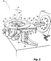
Fig. 2 is a schematic perspective view of an embodiment of the additive manufacturing system ofFig. 1 showing a two-axis depowdering system without an additively manufactured part; and -
Fig. 3 is a schematic perspective view of an ultrasonic transducer system of the additive manufacturing system ofFig. 1 . - Reference will now be made to the drawings wherein like reference numerals identify similar structural features or aspects of the subject disclosure. For purposes of explanation and illustration, and not limitation, a partial view of an embodiment of a system in accordance with the disclosure is shown in
Fig. 1 and is designated generally byreference character 100. Other embodiments of systems in accordance with the disclosure, or aspects thereof, are provided inFigs. 2-3 , as will be described. The systems and methods described herein can be used to depowder additively manufactured parts. - After parts are additively manufactured, for example using a laser powder bed fusion method, or other powder sintering method, excess powder must be removed from the parts. To do so efficiently and safely, especially from internal features, can require applying directional and/or rotational forces to the additively manufactured parts. A
system 100 for depowdering additively such manufacturedparts 102 can include a build plate 104 mounted to a first side 106 of amounting plate 108 with a plurality of fasteners 110 (e.g. bolts). Thefasteners 110 can engage themounting plate 108 in part through arespective die spring 112 for eachfastener 110. Using die-springs 112 under heads of thefasteners 110 protects thefasteners 110 and allows for resonant bounce between build plate 104 andmounting plate 108. - The
mounting plate 108 can include aninner hub 114 and anouter rim 116 connected to one another by a plurality ofradial spokes 118. Thespokes 118 allow for more deflection than would otherwise be possible with asolid mounting plate 108, and ultimately for improved resonance through the build plate 104 andpar 102 for improved powder removal. Therim 116 of themounting plate 108 can include a plurality of sets offastener holes 120 configured to receivefasteners 110 of a variety of different build plate configurations. For example, thefastener holes 120 can be indexed (e.g. using lettering and/or numbering system) to correspond to known build plate configurations to assist in mounting and remounting the build plate 104 during cleaning. This can be beneficial if thesystem 100 is being implemented as a retrofit, for example. - A
deflection plate 122 can be mounted to asecond side 124 of themounting plate 108 such that themounting plate 108 can rotate to thedeflection plate 122 about axis R1. A hammer device 126 (e.g. a pneumatic hammer) can be mounted to afirst side 128 of thedeflection plate 122, opposite themounting plate 108. Thedeflection plate 122 can include alip 130 for contacting themounting plate 108 through actuation of thehammer device 126. In this way, only thelip 130 of thedeflecting plate 122 contacts themounting plate 108. The directional forces from thehammer device 126 are applied to the build plate through both thedeflection plate 122 and themounting plate 108, so as not to contact or cause damage to the build plate 104 orpart 102. Aretention plate 132 can be mounted to the deflection plate 122 (e.g. along a chordal major diameter) so that a portion of themounting plate 108 is sandwiched between thedeflection plate 122 andretention plate 132. Theretention plate 132 thus provides additional support to themounting plate 108, for example for heavier build plates 104 and/orparts 102. - An
arm 134 can connect between anarm actuator 136 and thedeflection plate 122 such that thearm actuator 136 is configured to rotate thearm 134 anddeflection plate 122 together through 350° of rotation back and forth about an arm axis R2 defined along the length of thearm 134. Aplate actuator 138 can be connected to thedeflection plate 122 and to themounting plate 108 for actuating rotation of themounting plate 108 relative to thedeflection plate 122 within a plane PI parallel to a plane P2 defined bysecond side 129 of thedeflection plate 122. Theplate actuator 138 can be configured to rotate the mounting plate through 80° of rotation back and forth (e.g. between notches 139) about a plate axis R1 perpendicular to thesecond side 129 of thedeflection plate 122, and perpendicular to the arm axis R2. The combined rotation of thearm 134 and the mountingplate 108 allow for two-axis rotation, changing force origin and resonance signature, provided a more effective powder removal. - An
ultrasonic transducer system 140 can be mounted to the mountingplate 108 for inducing ultrasonic vibrations into the mountingplate 108, for example for multi-stage powder removal techniques and recipes. The ultrasonic transducer system can include at least one ultrasonictransducer ring mount 142 mounted to the mountingplate 108. Eachring mount 142 can include areceptacle 144 for mounting a respectiveultrasonic transducer 146 thereto.Transducer ring mount 142 can allow the ultrasonic vibrations to clean thepart 102, but will deflects when thehammer device 126 is actuated and applied to the mounting plate, protecting thetransducer 146. For example, parametric adjustment of the present embodiment allows for the intended amplitude of energy transfer, while deflecting the hammer forces to reduce unintentional transfer of energy back to transducer component, which can be fragile and sensitive to the forces of thehammer device 126. Theultrasonic transducers 146 can be of an electrically insulative material protecting operators and surrounding equipment in event of transducer electrical fault, and can be hardened against explosion for safe use with explosive powder. - The at least one ultrasonic
transducer ring mount 142 can be a pair of ultrasonic transducer ring mounts 142a,b, for example to mountmultiple transducers 146 having the same or different frequencies. As shown, a first ultrasonic transducer 146a can be mounted to a first one of the ultrasonic transducer ring mounts 142a, and a second ultrasonic transducer 146b can be mounted to a second one of the ultrasonic transducer ring mounts 142b. The frequencies of the ultrasonic transducers can be the same or different, for example the first transducer 146a can have a frequency of 28kHz, and the second transducer 146b can have a frequency of 40kHz however any suitable transducer frequency can be used. - A controller 148 can be operatively connected to the
system 100 to control movement of the mountingplate 108, and actuation of thehammer device 126 andtransducer system 140. For example, the controller 148 can include machine-readable instructions configured to cause the controller to rotate the build plate through two axes of rotation, including yaw, pitch, and roll angles and to remove powder while doing so by controlling the hammer device to vibrate the build plate. The controller 148 can also be connected to theultrasonic transducer system 140 to drive ultrasonic vibrations from theultrasonic transducer system 140 into the build plate 104 through the mountingplate 108. The controller 148 can control theultrasonic transducer system 140 to sweep through a range of resonant frequencies and amplitudes as needed for cleaning. - The methods and systems of the present disclosure, as described above and shown in the drawings, provide for improved depowdering without the need for manual blows applied directly to the build plate/and or finished part. Moreover, the
system 100 can be incorporated into existing additive manufacturing systems that require inert environments for reactive powders. While the apparatus and methods of the subject disclosure have been shown and described, those skilled in the art will readily appreciate that changes and/or modifications may be made thereto without departing from the scope of the subject disclosure.
Claims (15)
- A system for depowdering additively manufactured parts, the system comprising:a deflection plate (122);a hammer device (126) mounted to a first side (128) of the deflection plate (122); anda mounting plate (108) operatively connected to a second side of the deflection plate (122) relative to the hammer device (126), the mounting plate (108) being configured for rotation relative to the deflection plate (122).
- The system as recited in claim 1, further comprising an ultrasonic transducer system (140) mounted to the mounting plate (108) for inducing ultrasonic vibrations into the mounting plate.
- The system as recited in claim 2, wherein the ultrasonic transducer system (140) includes at least one ultrasonic transducer ring mount (142) mounted to the mounting plate, wherein each ring mount includes a receptacle for mounting a respective ultrasonic transducer (146) thereto.
- The system as recited in claim 3, wherein the at least one ultrasonic transducer ring mounts (142) is a pair of ultrasonic transducer ring mounts (142a,b), wherein a first ultrasonic transducer (146a) having a first frequency is mounted to a first one of the ultrasonic transducer ring mounts (146b), and a second ultrasonic transducer (146b) having a second frequency is mounted to a second one of the ultrasonic transducer ring mounts (142b).
- The system as recited in claim 4, wherein the first frequency of the first ultrasonic transducer (146a) is different than the second frequency of the second ultrasonic transducer (146b).
- The system as recited in claim 4, wherein the ultrasonic transducers (146) are hardened against explosion for safe use with explosive powder.
- The system as recited in any preceding claim, further comprising an arm (134) connecting between an arm actuator (136) and the deflection plate (122).
- The system as recited in claim 7, wherein the arm actuator (136) is configured to rotate the arm (134) and deflection plate through 350° of rotation back and forth about an arm axis defined along the arm (134).
- The system as recited in any preceding claim, further comprising a plate actuator (138) connected to the deflection plate (122) and to the mounting plate (108) for actuating rotation of the mounting plate relative to the deflection plate, and preferably wherein the plate actuator (138) is connected to the deflection plate (122) and to the mounting plate (108) to rotate the mounting plate within a plane parallel to a plane defined by the second surface of the deflection plate, and more preferably wherein the plate actuator (138) is configured to rotate the mounting plate through 80° of rotation back and forth about a plate axis perpendicular to the second surface of the deflection plate.
- The system as recited in any preceding claim, wherein the mounting plate (108) includes an inner hub (114) and an outer rim (116) connected to one another by a plurality of radial spokes (118), and preferably wherein the rim of the mounting plate includes a plurality of sets of fastener holes (120) configured to receive fasteners (110) of a variety of different build plate configurations.
- The system as recited in any preceding claim, wherein the deflection plate (122) includes a lip (130), wherein only the lip of the deflection plate contacts the mounting plate (108).
- The system as recited in any preceding claim, further comprising a retention plate (132) mounted to the deflection plate (122) with a portion of the mounting plate (108) between the deflection plate and retention plate.
- The system as recited in claim 2, further comprising a controller (148) operatively connected to control movement of the mounting plate (108) and actuation of the hammer device (126) and ultrasonic transducer system (140), wherein the controller (148) includes machine-readable instructions configured to cause the controller to rotate a build plate fixed to the mounting plate through yaw, pitch, and roll angles and to remove powder while doing so by controlling the hammer device and ultrasonic transducer system to vibrate the build plate.
- The system as recited in claim 13, wherein the machine-readable instructions include instructions to rotate a two axis system of actuators to rotate the mounting plate through yaw, pitch, and roll; and/or
wherein the controller (148) is connected to an ultrasonic transducer system (140), and wherein the machine-readable instructions include instructions to drive ultrasonic vibrations from the ultrasonic transducer system into the build plate, and preferably wherein the machine readable instructions include instructions to sweep the ultrasonic transducer system through a range of resonant frequencies. - The system as recited in any preceding claim, further comprising a build plate (104) including an additively manufactured build, wherein the build plate (104) is mounted to the mounting plate (108) with a plurality of fasteners (110), wherein the fasteners (110) engage the mounting plate (108) in part through a respective die spring (112) for each fastener.
Applications Claiming Priority (1)
| Application Number | Priority Date | Filing Date | Title |
|---|---|---|---|
| US17/221,460 US12157272B2 (en) | 2021-04-02 | 2021-04-02 | Two-axis depowdering |
Publications (2)
| Publication Number | Publication Date |
|---|---|
| EP4066950A1 true EP4066950A1 (en) | 2022-10-05 |
| EP4066950B1 EP4066950B1 (en) | 2025-05-21 |
Family
ID=81306815
Family Applications (1)
| Application Number | Title | Priority Date | Filing Date |
|---|---|---|---|
| EP22166031.9A Active EP4066950B1 (en) | 2021-04-02 | 2022-03-31 | Two-axis depowdering |
Country Status (2)
| Country | Link |
|---|---|
| US (1) | US12157272B2 (en) |
| EP (1) | EP4066950B1 (en) |
Cited By (1)
| Publication number | Priority date | Publication date | Assignee | Title |
|---|---|---|---|---|
| EP4238665A1 (en) * | 2022-03-04 | 2023-09-06 | Hamilton Sundstrand Corporation | High amplitude pneumatic impact for powder removal in additive manufacturing |
Families Citing this family (3)
| Publication number | Priority date | Publication date | Assignee | Title |
|---|---|---|---|---|
| FR3141357B1 (en) * | 2022-10-28 | 2026-03-06 | Safran Additive Mfg Campus | Dust removal device and dust removal process |
| US20240139821A1 (en) * | 2022-11-01 | 2024-05-02 | Divergent Technologies, Inc. | Depowdering of 3d-printed structures |
| CN118106295A (en) * | 2024-04-03 | 2024-05-31 | 哈尔滨工业大学 | A composite ultrasonic vibration device for high-speed railway pantograph |
Citations (3)
| Publication number | Priority date | Publication date | Assignee | Title |
|---|---|---|---|---|
| US20170036401A1 (en) * | 2015-08-03 | 2017-02-09 | Delavan Inc. | Systems and methods for post additive manufacturing processing |
| EP3257607A1 (en) * | 2016-06-13 | 2017-12-20 | Siemens Aktiengesellschaft | Apparatus for additive manufacturing and use of the apparatus |
| EP3527304A1 (en) * | 2018-02-19 | 2019-08-21 | Siemens Aktiengesellschaft | Device and method for separating a material of at least one component produced using additive manufacture |
Family Cites Families (4)
| Publication number | Priority date | Publication date | Assignee | Title |
|---|---|---|---|---|
| DE102018008738A1 (en) | 2018-02-19 | 2019-08-22 | Solukon Ingenieure GbR (vertretungsberechtigte Gesellschafter: Andreas Hartmann, 86391 Stadtbergen und Dominik Schmid, 86165 Augsburg) | CLEANING DEVICE FOR CLEANING THREE-DIMENSIONAL OBJECTS |
| US20200376786A1 (en) | 2019-05-31 | 2020-12-03 | Hamilton Sundstrand Corporation | Treatment processes and systems for additively formed components |
| CN111113901B (en) | 2020-01-03 | 2021-05-25 | 燕山大学 | Inside powder cleaning device of 3D printing part based on reciprocating linear motion |
| CN112046004A (en) | 2020-09-16 | 2020-12-08 | 北京钢研高纳科技股份有限公司 | Powder cleaning device and 3D printing parts processing system |
-
2021
- 2021-04-02 US US17/221,460 patent/US12157272B2/en active Active
-
2022
- 2022-03-31 EP EP22166031.9A patent/EP4066950B1/en active Active
Patent Citations (3)
| Publication number | Priority date | Publication date | Assignee | Title |
|---|---|---|---|---|
| US20170036401A1 (en) * | 2015-08-03 | 2017-02-09 | Delavan Inc. | Systems and methods for post additive manufacturing processing |
| EP3257607A1 (en) * | 2016-06-13 | 2017-12-20 | Siemens Aktiengesellschaft | Apparatus for additive manufacturing and use of the apparatus |
| EP3527304A1 (en) * | 2018-02-19 | 2019-08-21 | Siemens Aktiengesellschaft | Device and method for separating a material of at least one component produced using additive manufacture |
Cited By (2)
| Publication number | Priority date | Publication date | Assignee | Title |
|---|---|---|---|---|
| EP4238665A1 (en) * | 2022-03-04 | 2023-09-06 | Hamilton Sundstrand Corporation | High amplitude pneumatic impact for powder removal in additive manufacturing |
| US11878470B2 (en) | 2022-03-04 | 2024-01-23 | Hamilton Sundstrand Corporation | High amplitude pneumatic impact for powder removal in additive manufacturing |
Also Published As
| Publication number | Publication date |
|---|---|
| US20220314546A1 (en) | 2022-10-06 |
| US12157272B2 (en) | 2024-12-03 |
| EP4066950B1 (en) | 2025-05-21 |
Similar Documents
| Publication | Publication Date | Title |
|---|---|---|
| EP4066950B1 (en) | Two-axis depowdering | |
| EP2657006B1 (en) | System for mounting ultrasonic tools | |
| US8975552B2 (en) | Workpiece holder for holding a plurality of plate workpieces used for wire electric discharge machine | |
| US6098514A (en) | Ultrasonic vibration cutter | |
| US9346120B1 (en) | Sonotrode apparatus for use in ultrasonic additive manufacturing | |
| JP2011104727A (en) | Workpiece machining device and workpiece machining method | |
| WO2017215921A1 (en) | Apparatus for additive manufacturing and use of the apparatus | |
| JP2012240159A (en) | Ultrasonic cutting device | |
| CN113084853A (en) | Flexible gripper at tail end of robot | |
| US20230060565A1 (en) | Apparatus, system and method for automated speaker assembly | |
| US20090007996A1 (en) | Method for Vibrating a Substrate During Material Formation | |
| EP2679836B1 (en) | Pre-tensioned breakaway fastener | |
| JP3445262B2 (en) | Piezoelectric body manufacturing method, piezoelectric body, ultrasonic probe, ultrasonic diagnostic apparatus, and nondestructive inspection apparatus | |
| JPH11221682A (en) | Ultrasonic bonding method and apparatus for metal foil | |
| US20090074985A1 (en) | Method for Vibrating a Substrate During Material Formation | |
| CN111069797B (en) | Automatic device and method for forming micropores of foil through laser high-speed impact | |
| CN113909877A (en) | Aircraft part deformation correction assembly quality | |
| JPS6297677A (en) | Twist vibrator | |
| EP4015163B1 (en) | Gripping tool | |
| CN213224713U (en) | Electrode cap replacing device for welding electrode and vehicle production system | |
| EP4349497A2 (en) | Converter for an ultrasonic welding device having increased arc resistance | |
| CN216403118U (en) | Clamping device of stacker crane | |
| US20240120551A1 (en) | Device for intercepting pickup of multiple electrodes | |
| CN119346993A (en) | Device and method for ultrasonic vibration chamfering of inner wall holes of tubular composite materials | |
| JP2747014B2 (en) | Laser processing machine |
Legal Events
| Date | Code | Title | Description |
|---|---|---|---|
| PUAI | Public reference made under article 153(3) epc to a published international application that has entered the european phase |
Free format text: ORIGINAL CODE: 0009012 |
|
| STAA | Information on the status of an ep patent application or granted ep patent |
Free format text: STATUS: THE APPLICATION HAS BEEN PUBLISHED |
|
| AK | Designated contracting states |
Kind code of ref document: A1 Designated state(s): AL AT BE BG CH CY CZ DE DK EE ES FI FR GB GR HR HU IE IS IT LI LT LU LV MC MK MT NL NO PL PT RO RS SE SI SK SM TR |
|
| STAA | Information on the status of an ep patent application or granted ep patent |
Free format text: STATUS: REQUEST FOR EXAMINATION WAS MADE |
|
| 17P | Request for examination filed |
Effective date: 20230403 |
|
| RBV | Designated contracting states (corrected) |
Designated state(s): AL AT BE BG CH CY CZ DE DK EE ES FI FR GB GR HR HU IE IS IT LI LT LU LV MC MK MT NL NO PL PT RO RS SE SI SK SM TR |
|
| P01 | Opt-out of the competence of the unified patent court (upc) registered |
Effective date: 20230922 |
|
| GRAP | Despatch of communication of intention to grant a patent |
Free format text: ORIGINAL CODE: EPIDOSNIGR1 |
|
| STAA | Information on the status of an ep patent application or granted ep patent |
Free format text: STATUS: GRANT OF PATENT IS INTENDED |
|
| INTG | Intention to grant announced |
Effective date: 20241219 |
|
| RIN1 | Information on inventor provided before grant (corrected) |
Inventor name: SKIBA, TOMMY Inventor name: GUSTAFSON, BRENDAN T. Inventor name: MORGANSON, DAVID W. |
|
| GRAS | Grant fee paid |
Free format text: ORIGINAL CODE: EPIDOSNIGR3 |
|
| GRAA | (expected) grant |
Free format text: ORIGINAL CODE: 0009210 |
|
| STAA | Information on the status of an ep patent application or granted ep patent |
Free format text: STATUS: THE PATENT HAS BEEN GRANTED |
|
| AK | Designated contracting states |
Kind code of ref document: B1 Designated state(s): AL AT BE BG CH CY CZ DE DK EE ES FI FR GB GR HR HU IE IS IT LI LT LU LV MC MK MT NL NO PL PT RO RS SE SI SK SM TR |
|
| REG | Reference to a national code |
Ref country code: GB Ref legal event code: FG4D |
|
| REG | Reference to a national code |
Ref country code: CH Ref legal event code: EP |
|
| REG | Reference to a national code |
Ref country code: DE Ref legal event code: R096 Ref document number: 602022014836 Country of ref document: DE |
|
| REG | Reference to a national code |
Ref country code: IE Ref legal event code: FG4D |
|
| REG | Reference to a national code |
Ref country code: NL Ref legal event code: MP Effective date: 20250521 |
|
| PG25 | Lapsed in a contracting state [announced via postgrant information from national office to epo] |
Ref country code: PT Free format text: LAPSE BECAUSE OF FAILURE TO SUBMIT A TRANSLATION OF THE DESCRIPTION OR TO PAY THE FEE WITHIN THE PRESCRIBED TIME-LIMIT Effective date: 20250922 Ref country code: ES Free format text: LAPSE BECAUSE OF FAILURE TO SUBMIT A TRANSLATION OF THE DESCRIPTION OR TO PAY THE FEE WITHIN THE PRESCRIBED TIME-LIMIT Effective date: 20250521 Ref country code: FI Free format text: LAPSE BECAUSE OF FAILURE TO SUBMIT A TRANSLATION OF THE DESCRIPTION OR TO PAY THE FEE WITHIN THE PRESCRIBED TIME-LIMIT Effective date: 20250521 |
|
| REG | Reference to a national code |
Ref country code: LT Ref legal event code: MG9D |
|
| PG25 | Lapsed in a contracting state [announced via postgrant information from national office to epo] |
Ref country code: NO Free format text: LAPSE BECAUSE OF FAILURE TO SUBMIT A TRANSLATION OF THE DESCRIPTION OR TO PAY THE FEE WITHIN THE PRESCRIBED TIME-LIMIT Effective date: 20250821 Ref country code: GR Free format text: LAPSE BECAUSE OF FAILURE TO SUBMIT A TRANSLATION OF THE DESCRIPTION OR TO PAY THE FEE WITHIN THE PRESCRIBED TIME-LIMIT Effective date: 20250822 |
|
| PG25 | Lapsed in a contracting state [announced via postgrant information from national office to epo] |
Ref country code: NL Free format text: LAPSE BECAUSE OF FAILURE TO SUBMIT A TRANSLATION OF THE DESCRIPTION OR TO PAY THE FEE WITHIN THE PRESCRIBED TIME-LIMIT Effective date: 20250521 Ref country code: PL Free format text: LAPSE BECAUSE OF FAILURE TO SUBMIT A TRANSLATION OF THE DESCRIPTION OR TO PAY THE FEE WITHIN THE PRESCRIBED TIME-LIMIT Effective date: 20250521 |
|
| PG25 | Lapsed in a contracting state [announced via postgrant information from national office to epo] |
Ref country code: BG Free format text: LAPSE BECAUSE OF FAILURE TO SUBMIT A TRANSLATION OF THE DESCRIPTION OR TO PAY THE FEE WITHIN THE PRESCRIBED TIME-LIMIT Effective date: 20250521 |
|
| PG25 | Lapsed in a contracting state [announced via postgrant information from national office to epo] |
Ref country code: HR Free format text: LAPSE BECAUSE OF FAILURE TO SUBMIT A TRANSLATION OF THE DESCRIPTION OR TO PAY THE FEE WITHIN THE PRESCRIBED TIME-LIMIT Effective date: 20250521 |
|
| PG25 | Lapsed in a contracting state [announced via postgrant information from national office to epo] |
Ref country code: RS Free format text: LAPSE BECAUSE OF FAILURE TO SUBMIT A TRANSLATION OF THE DESCRIPTION OR TO PAY THE FEE WITHIN THE PRESCRIBED TIME-LIMIT Effective date: 20250821 |
|
| PG25 | Lapsed in a contracting state [announced via postgrant information from national office to epo] |
Ref country code: IS Free format text: LAPSE BECAUSE OF FAILURE TO SUBMIT A TRANSLATION OF THE DESCRIPTION OR TO PAY THE FEE WITHIN THE PRESCRIBED TIME-LIMIT Effective date: 20250921 |
|
| PG25 | Lapsed in a contracting state [announced via postgrant information from national office to epo] |
Ref country code: LV Free format text: LAPSE BECAUSE OF FAILURE TO SUBMIT A TRANSLATION OF THE DESCRIPTION OR TO PAY THE FEE WITHIN THE PRESCRIBED TIME-LIMIT Effective date: 20250521 |
|
| REG | Reference to a national code |
Ref country code: AT Ref legal event code: MK05 Ref document number: 1796352 Country of ref document: AT Kind code of ref document: T Effective date: 20250521 |
|
| PG25 | Lapsed in a contracting state [announced via postgrant information from national office to epo] |
Ref country code: AT Free format text: LAPSE BECAUSE OF FAILURE TO SUBMIT A TRANSLATION OF THE DESCRIPTION OR TO PAY THE FEE WITHIN THE PRESCRIBED TIME-LIMIT Effective date: 20250521 Ref country code: SM Free format text: LAPSE BECAUSE OF FAILURE TO SUBMIT A TRANSLATION OF THE DESCRIPTION OR TO PAY THE FEE WITHIN THE PRESCRIBED TIME-LIMIT Effective date: 20250521 Ref country code: DK Free format text: LAPSE BECAUSE OF FAILURE TO SUBMIT A TRANSLATION OF THE DESCRIPTION OR TO PAY THE FEE WITHIN THE PRESCRIBED TIME-LIMIT Effective date: 20250521 |
|
| PG25 | Lapsed in a contracting state [announced via postgrant information from national office to epo] |
Ref country code: CZ Free format text: LAPSE BECAUSE OF FAILURE TO SUBMIT A TRANSLATION OF THE DESCRIPTION OR TO PAY THE FEE WITHIN THE PRESCRIBED TIME-LIMIT Effective date: 20250521 |
|
| PG25 | Lapsed in a contracting state [announced via postgrant information from national office to epo] |
Ref country code: EE Free format text: LAPSE BECAUSE OF FAILURE TO SUBMIT A TRANSLATION OF THE DESCRIPTION OR TO PAY THE FEE WITHIN THE PRESCRIBED TIME-LIMIT Effective date: 20250521 |
|
| PG25 | Lapsed in a contracting state [announced via postgrant information from national office to epo] |
Ref country code: SK Free format text: LAPSE BECAUSE OF FAILURE TO SUBMIT A TRANSLATION OF THE DESCRIPTION OR TO PAY THE FEE WITHIN THE PRESCRIBED TIME-LIMIT Effective date: 20250521 |
|
| PG25 | Lapsed in a contracting state [announced via postgrant information from national office to epo] |
Ref country code: IT Free format text: LAPSE BECAUSE OF FAILURE TO SUBMIT A TRANSLATION OF THE DESCRIPTION OR TO PAY THE FEE WITHIN THE PRESCRIBED TIME-LIMIT Effective date: 20250521 |
|
| REG | Reference to a national code |
Ref country code: DE Ref legal event code: R097 Ref document number: 602022014836 Country of ref document: DE |
|
| PLBE | No opposition filed within time limit |
Free format text: ORIGINAL CODE: 0009261 |
|
| STAA | Information on the status of an ep patent application or granted ep patent |
Free format text: STATUS: NO OPPOSITION FILED WITHIN TIME LIMIT |
|
| REG | Reference to a national code |
Ref country code: CH Ref legal event code: L10 Free format text: ST27 STATUS EVENT CODE: U-0-0-L10-L00 (AS PROVIDED BY THE NATIONAL OFFICE) Effective date: 20260402 |
|
| PGFP | Annual fee paid to national office [announced via postgrant information from national office to epo] |
Ref country code: GB Payment date: 20260219 Year of fee payment: 5 |
|
| PGFP | Annual fee paid to national office [announced via postgrant information from national office to epo] |
Ref country code: DE Payment date: 20260219 Year of fee payment: 5 |
|
| PGFP | Annual fee paid to national office [announced via postgrant information from national office to epo] |
Ref country code: FR Payment date: 20260219 Year of fee payment: 5 |
|
| 26N | No opposition filed |
Effective date: 20260224 |
|
| PG25 | Lapsed in a contracting state [announced via postgrant information from national office to epo] |
Ref country code: LT Free format text: LAPSE BECAUSE OF FAILURE TO SUBMIT A TRANSLATION OF THE DESCRIPTION OR TO PAY THE FEE WITHIN THE PRESCRIBED TIME-LIMIT Effective date: 20250521 |
|
| PG25 | Lapsed in a contracting state [announced via postgrant information from national office to epo] |
Ref country code: SE Free format text: LAPSE BECAUSE OF FAILURE TO SUBMIT A TRANSLATION OF THE DESCRIPTION OR TO PAY THE FEE WITHIN THE PRESCRIBED TIME-LIMIT Effective date: 20250521 |