EP4066744B1 - Bildverarbeitungsvorrichtung, bildverarbeitungsverfahren und bildverarbeitungsprogramm - Google Patents
Bildverarbeitungsvorrichtung, bildverarbeitungsverfahren und bildverarbeitungsprogramm Download PDFInfo
- Publication number
- EP4066744B1 EP4066744B1 EP22162213.7A EP22162213A EP4066744B1 EP 4066744 B1 EP4066744 B1 EP 4066744B1 EP 22162213 A EP22162213 A EP 22162213A EP 4066744 B1 EP4066744 B1 EP 4066744B1
- Authority
- EP
- European Patent Office
- Prior art keywords
- spicula
- tomographic
- candidate region
- image
- image processing
- Prior art date
- Legal status (The legal status is an assumption and is not a legal conclusion. Google has not performed a legal analysis and makes no representation as to the accuracy of the status listed.)
- Active
Links
Images



Classifications
-
- A—HUMAN NECESSITIES
- A61—MEDICAL OR VETERINARY SCIENCE; HYGIENE
- A61B—DIAGNOSIS; SURGERY; IDENTIFICATION
- A61B6/00—Apparatus or devices for radiation diagnosis; Apparatus or devices for radiation diagnosis combined with radiation therapy equipment
- A61B6/52—Devices using data or image processing specially adapted for radiation diagnosis
- A61B6/5211—Devices using data or image processing specially adapted for radiation diagnosis involving processing of medical diagnostic data
- A61B6/5229—Devices using data or image processing specially adapted for radiation diagnosis involving processing of medical diagnostic data combining image data of a patient, e.g. combining a functional image with an anatomical image
- A61B6/5235—Devices using data or image processing specially adapted for radiation diagnosis involving processing of medical diagnostic data combining image data of a patient, e.g. combining a functional image with an anatomical image combining images from the same or different ionising radiation imaging techniques, e.g. PET and CT
-
- A—HUMAN NECESSITIES
- A61—MEDICAL OR VETERINARY SCIENCE; HYGIENE
- A61B—DIAGNOSIS; SURGERY; IDENTIFICATION
- A61B6/00—Apparatus or devices for radiation diagnosis; Apparatus or devices for radiation diagnosis combined with radiation therapy equipment
- A61B6/02—Arrangements for diagnosis sequentially in different planes; Stereoscopic radiation diagnosis
- A61B6/025—Tomosynthesis
-
- A—HUMAN NECESSITIES
- A61—MEDICAL OR VETERINARY SCIENCE; HYGIENE
- A61B—DIAGNOSIS; SURGERY; IDENTIFICATION
- A61B6/00—Apparatus or devices for radiation diagnosis; Apparatus or devices for radiation diagnosis combined with radiation therapy equipment
- A61B6/50—Apparatus or devices for radiation diagnosis; Apparatus or devices for radiation diagnosis combined with radiation therapy equipment specially adapted for specific body parts; specially adapted for specific clinical applications
- A61B6/502—Apparatus or devices for radiation diagnosis; Apparatus or devices for radiation diagnosis combined with radiation therapy equipment specially adapted for specific body parts; specially adapted for specific clinical applications for diagnosis of breast, i.e. mammography
-
- A—HUMAN NECESSITIES
- A61—MEDICAL OR VETERINARY SCIENCE; HYGIENE
- A61B—DIAGNOSIS; SURGERY; IDENTIFICATION
- A61B6/00—Apparatus or devices for radiation diagnosis; Apparatus or devices for radiation diagnosis combined with radiation therapy equipment
- A61B6/52—Devices using data or image processing specially adapted for radiation diagnosis
- A61B6/5211—Devices using data or image processing specially adapted for radiation diagnosis involving processing of medical diagnostic data
- A61B6/5217—Devices using data or image processing specially adapted for radiation diagnosis involving processing of medical diagnostic data extracting a diagnostic or physiological parameter from medical diagnostic data
-
- A—HUMAN NECESSITIES
- A61—MEDICAL OR VETERINARY SCIENCE; HYGIENE
- A61B—DIAGNOSIS; SURGERY; IDENTIFICATION
- A61B6/00—Apparatus or devices for radiation diagnosis; Apparatus or devices for radiation diagnosis combined with radiation therapy equipment
- A61B6/52—Devices using data or image processing specially adapted for radiation diagnosis
- A61B6/5211—Devices using data or image processing specially adapted for radiation diagnosis involving processing of medical diagnostic data
- A61B6/5223—Devices using data or image processing specially adapted for radiation diagnosis involving processing of medical diagnostic data generating planar views from image data, e.g. extracting a coronal view from a 3D image
-
- G—PHYSICS
- G06—COMPUTING OR CALCULATING; COUNTING
- G06T—IMAGE DATA PROCESSING OR GENERATION, IN GENERAL
- G06T7/00—Image analysis
- G06T7/0002—Inspection of images, e.g. flaw detection
- G06T7/0012—Biomedical image inspection
-
- G—PHYSICS
- G06—COMPUTING OR CALCULATING; COUNTING
- G06T—IMAGE DATA PROCESSING OR GENERATION, IN GENERAL
- G06T7/00—Image analysis
- G06T7/70—Determining position or orientation of objects or cameras
- G06T7/77—Determining position or orientation of objects or cameras using statistical methods
-
- G—PHYSICS
- G06—COMPUTING OR CALCULATING; COUNTING
- G06T—IMAGE DATA PROCESSING OR GENERATION, IN GENERAL
- G06T2207/00—Indexing scheme for image analysis or image enhancement
- G06T2207/10—Image acquisition modality
- G06T2207/10072—Tomographic images
- G06T2207/10081—Computed x-ray tomography [CT]
-
- G—PHYSICS
- G06—COMPUTING OR CALCULATING; COUNTING
- G06T—IMAGE DATA PROCESSING OR GENERATION, IN GENERAL
- G06T2207/00—Indexing scheme for image analysis or image enhancement
- G06T2207/20—Special algorithmic details
- G06T2207/20076—Probabilistic image processing
-
- G—PHYSICS
- G06—COMPUTING OR CALCULATING; COUNTING
- G06T—IMAGE DATA PROCESSING OR GENERATION, IN GENERAL
- G06T2207/00—Indexing scheme for image analysis or image enhancement
- G06T2207/20—Special algorithmic details
- G06T2207/20084—Artificial neural networks [ANN]
-
- G—PHYSICS
- G06—COMPUTING OR CALCULATING; COUNTING
- G06T—IMAGE DATA PROCESSING OR GENERATION, IN GENERAL
- G06T2207/00—Indexing scheme for image analysis or image enhancement
- G06T2207/30—Subject of image; Context of image processing
- G06T2207/30004—Biomedical image processing
- G06T2207/30068—Mammography; Breast
-
- G—PHYSICS
- G06—COMPUTING OR CALCULATING; COUNTING
- G06T—IMAGE DATA PROCESSING OR GENERATION, IN GENERAL
- G06T2207/00—Indexing scheme for image analysis or image enhancement
- G06T2207/30—Subject of image; Context of image processing
- G06T2207/30004—Biomedical image processing
- G06T2207/30096—Tumor; Lesion
Definitions
- the present disclosure relates to an image processing device, an image processing method, and an image processing program.
- mammography radiography apparatus
- tomosynthesis imaging which moves a radiation source, irradiates the breast with radiation at a plurality of radiation source positions to acquire a plurality of projection images, and reconstructs the acquired plurality of projection images to generate tomographic images in which desired tomographic planes have been highlighted.
- the radiation source is moved in parallel to a radiation detector or is moved to draw a circular or elliptical arc, according to the characteristics of an imaging apparatus and the required tomographic images, and the breast is imaged at a plurality of radiation source positions to acquire a plurality of projection images. Then, the acquired plurality of projection images are reconstructed, using a back projection method, such as a simple back projection method or a filtered back projection method, or an iterative reconstruction method, to generate tomographic images.
- a back projection method such as a simple back projection method or a filtered back projection method, or an iterative reconstruction method
- the tomographic images are generated in a plurality of tomographic planes of the breast, which makes it possible to separate structures that overlap each other in a depth direction in which the tomographic planes are arranged in the breast. Therefore, it is possible to find an abnormal part, such as a lesion, that has been difficult to detect in a two-dimensional image (hereinafter, referred to as a simple two-dimensional image) acquired by simple imaging according to the related art which irradiates an object with radiation in a predetermined direction.
- a two-dimensional image hereinafter, referred to as a simple two-dimensional image
- a technique which combines a plurality of tomographic images having different distances (positions in a height direction) from a detection surface of a radiation detector to a radiation source, which have been acquired by tomosynthesis imaging, using, for example, an addition method, an averaging method, a maximum intensity projection method, or a minimum intensity projection method, to generate a pseudo two-dimensional image (hereinafter, referred to as a "composite two-dimensional image”) corresponding to the simple two-dimensional image (see JP2014-128716A ).
- a technique which discriminates an object that is a candidate for a lesion or the like from three-dimensional volume data, tags tomographic images, and performs forward projection on a plurality of tagged tomographic images to generate a composite two-dimensional image, in order to improve the discrimination of the lesion or the like (see JP2015-515296A ).
- Image processing techniques are also disclosed in WO 2020/202612 A1 and WO 2018/183548 .
- JP2015-515296A does not disclose a technique which detects a spicula that is a candidate for a lesion or the like.
- the spicula is a radial line structure that is generated by drawing surrounding tissues while breast cancer is growing.
- Some normal mammary glands have a radial structure that is confusable with the spicula.
- three-dimensional analysis is also performed in order to discriminate an object that is a candidate for a lesion or the like from a three-dimensional image (3D volume data).
- the three-dimensional analysis has a problem that it takes a lot of time to perform processes.
- the present disclosure has been made in view of the above circumstances, and an object of the present disclosure is to provide an image processing device, an image processing method, and an image processing program that can accurately detect a spicula in a short processing time.
- an image processing device as defined by claim 1.
- the processor analyzes the composite two-dimensional image to determine whether or not the spicula candidate region is a spicula.
- the processor performs control to display the composite two-dimensional image and performs control to display a result of determining whether or not the spicula candidate region is the spicula on the composite two-dimensional image.
- an image processing device an image processing method, and an image processing program that can accurately detect a spicula in a short processing time.
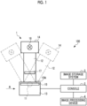
- the radiography system 100 images a breast M, which is an object, at a plurality of radiation source positions and acquires a plurality of radiographic images, that is, a plurality of projection images, in order to perform tomosynthesis imaging on the breast to generate tomographic images.
- the radiography system 100 comprises a mammography apparatus 1, a console 2, an image storage system 3, and an image processing device 4.
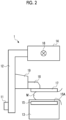
- the mammography apparatus 1 comprises an arm portion 12 that is connected to a base (not illustrated) by a rotation shaft 11.
- An imaging table 13 is attached to one end of the arm portion 12, and a radiation emitting unit 14 is attached to the other end of the arm portion 12 so as to face the imaging table 13.
- the arm portion 12 is configured such that only the end to which the radiation emitting unit 14 is attached can be rotated. Therefore, the imaging table 13 is fixed, and only the radiation emitting unit 14 can be rotated.
- the radiation detector 15 has a radiation detection surface 15A.
- a circuit substrate including a charge amplifier that converts a charge signal read out from the radiation detector 15 into a voltage signal, a correlated double sampling circuit that samples the voltage signal output from the charge amplifier, and an analog-to-digital (AD) conversion unit that converts the voltage signal into a digital signal is provided in the imaging table 13.
- AD analog-to-digital
- a radiation source 16 is accommodated in the radiation emitting unit 14.
- the radiation source 16 emits X-rays as radiation.
- the console 2 controls the timing when the radiation source 16 emits the radiation and radiation generation conditions (for example, a tube voltage and an irradiation time) of the radiation source 16.
- the arm portion 12 is provided with a compression plate 17 that is disposed above the imaging table 13 and compresses the breast M, a support portion 18 that supports the compression plate 17, and a movement mechanism 19 that moves the support portion 18 in an up-down direction. Furthermore, an interval between the compression plate 17 and the imaging table 13, that is, the thickness of the compressed breast is input to the console 2.
- the console 2 has a function of controlling the mammography apparatus 1 using, for example, an imaging order and various kinds of information acquired from a radiology information system (RIS) (not illustrated) or the like through a network, such as a wireless communication local area network (LAN), and instructions or the like directly issued by an engineer or the like.
- RIS radiology information system
- LAN wireless communication local area network
- the console 2 directs the mammography apparatus 1 to perform the tomosynthesis imaging on the breast M, acquires a plurality of projection images as described below, and reconstructs the plurality of projection images to generate a plurality of tomographic images.
- a server computer is used as the console 2.
- the image storage system 3 is a system that stores image data such as radiographic images and tomographic images captured by the mammography apparatus 1.
- the image storage system 3 extracts image data corresponding to a request from, for example, the console 2 and the image processing device 4 from the stored image data and transmits the image data to a device that is the source of the request.
- a specific example of the image storage system 3 is a picture archiving and communication system (PACS).
- PACS picture archiving and communication system
- the image processing device 4 includes a central processing unit (CPU) 20, a memory 21 as a temporary storage area, and a non-volatile storage unit 22.
- the image processing device 4 includes a display 23, such as a liquid crystal display, an input device 24, such as a keyboard and a mouse, and a network interface (I/F) 25 that is connected to the network.
- the CPU 20, the memory 21, the storage unit 22, the display 23, the input device 24, and the network I/F 25 are connected to a bus 27.
- the CPU 20 is an example of a "processor" according to the technology of the present disclosure.
- the storage unit 22 is implemented by, for example, a hard disk drive (HDD), a solid state drive (SSD), or a flash memory.
- An image processing program 30 is stored in the storage unit 22 as a storage medium.
- the CPU 20 reads out the image processing program 30 from the storage unit 22, expands the image processing program 30 in the memory 21, and executes the expanded image processing program 30.
- the image processing device 4 includes an acquisition unit 40, a detection unit 42, a selection unit 44, a combination unit 46, a determination unit 48, and a display control unit 50.
- the CPU 20 executes the image processing program 30 to function as the acquisition unit 40, the detection unit 42, the selection unit 44, the combination unit 46, the determination unit 48, and the display control unit 50.
- the acquisition unit 40 acquires a plurality of tomographic images generated by the tomosynthesis imaging performed by the mammography apparatus 1 under the control of the console 2.
- the acquisition unit 40 acquires a plurality of tomographic images from the console 2 or the image storage system 3 through the network I/F 25.
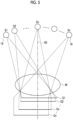
- the radiation detector 15 detects the radiation transmitted through the breast M to acquire the projection images G1, G2, ⁇ , Gn corresponding to the radiation source positions S1 to Sn, respectively.
- the same dose of radiation is emitted to the breast M at each of the radiation source positions S1 to Sn.
- a radiation source position Sc is a radiation source position where an optical axis X0 of the radiation emitted from the radiation source 16 is orthogonal to the detection surface 15A of the radiation detector 15.
- the radiation source position Sc is referred to as a reference radiation source position Sc.
- a three-dimensional coordinate position in a three-dimensional space including the breast M is set, and the pixel values of the corresponding pixels in the plurality of projection images Gi are reconstructed for the set three-dimensional coordinate position to calculate a pixel value at the coordinate position.
- the console 2 transmits the generated tomographic images Dj to the image processing device 4 or the image storage system 3.
- the detection unit 42 detects a region including a spicula candidate (hereinafter, referred to as a spicula candidate region) from each of the plurality of tomographic images Dj acquired by the acquisition unit 40.
- a spicula is a radial line structure (hereinafter, referred to as a radial structure) that is generated by drawing surrounding tissues while breast cancer is growing.
- the detection unit 42 detects, as the spicula candidate region, a region including line structures that extend radially from each of the tomographic images Dj. Further, in the tomographic image, a normal mammary gland is likely to appear as the radial structure similar to the spicula. Therefore, the spicula candidate region is likely to include the normal mammary gland.
- a tomographic image D2 includes a spicula candidate region K21
- a tomographic image D3 includes a spicula candidate region K31 and a spicula candidate region K32
- a tomographic image D4 includes a spicula candidate region K41 and a spicula candidate region K42
- a tomographic image D5 includes a spicula candidate region K51.
- the detection unit 42 detects the spicula candidate region from each of the plurality of tomographic images Dj using a known algorithm for detecting a spicula using computer aided diagnosis (CAD).
- CAD computer aided diagnosis
- a probability (likelihood) indicating that a pixel in the tomographic image Dj is the spicula candidate region is derived, and a pixel with a probability equal to or greater than a predetermined threshold value is detected as the spicula candidate region. It is difficult to distinguish between the spicula and the normal mammary gland that extends radially with only one tomographic image Dj. Therefore, the normal mammary gland that extends radially is also detected as the spicula candidate region.
- a process of detecting the spicula candidate region is not limited to the process using CAD.
- the process of detecting the spicula candidate region may be a process of detecting the spicula candidate region from the tomographic images Dj with a filtering process using a filter (for example, a radial filter).
- the process of detecting the spicula candidate region may be a process of detecting the spicula candidate region from the tomographic images Dj with a detection model or the like that has been subjected to machine learning by deep learning or the like.
- the selection unit 44 selects each tomographic image group corresponding to a plurality of spicula candidate regions that are presumed to indicate the same radial structure among the plurality of spicula candidate regions detected by the detection unit 42. For example, the selection unit 44 selects each tomographic image group corresponding to a plurality of spicula candidate regions which are included in a plurality of tomographic images Dj that are continuous in a thickness direction of the breast and have the same plane position in each of the tomographic images Dj.
- Substantially the same plane position in the tomographic images Dj means that, for example, in a case in which the spicula candidate regions are projected onto a plane parallel to the detection surface 15A, at least portions of the spicula candidate regions overlap between the tomographic images.
- the selection unit 44 presumes that the spicula candidate regions K21, K31, and K41 indicate the same radial structure and the spicula candidate regions K32, K42, and K51 indicate the same radial structure. Specifically, as illustrated in Fig. 8 , the selection unit 44 selects the tomographic images D2 to D4 as a first tomographic image group P1 since the spicula candidate regions K21, K31, and K41 are included in the continuous tomographic images D2 to D4, respectively, and have substantially the same plane position in the tomographic images D2 to D4.
- the selection unit 44 selects the tomographic images D2 to D4 as a second tomographic image group P2 since the spicula candidate regions K32, K42, and K51 are included in the continuous tomographic images D3 to D5, respectively, and have substantially the same plane position in the tomographic images D3 to D5.
- a region including the spicula candidate regions K21, K31, and K41 is referred to as a first region R1.
- a region including the spicula candidate regions K32, K42, and K51 is referred to as a second region R2.
- the first region R1 and the second region R2 are, for example, rectangular regions.
- the combination unit 46 generates a composite two-dimensional image SG using the tomographic image group selected by the selection unit 44.
- the composite two-dimensional image is a pseudo two-dimensional image corresponding to a simple two-dimensional image that is captured by irradiating the breast M with the radiation emitted at the reference radiation source position Sc (see Fig. 5 ).
- the combination unit 46 combines the pixel values of the corresponding pixels in each of the tomographic images Dj along a viewing direction from the reference radiation source position Sc to the radiation detector 15, that is, along the optical axis X0 (see Fig. 5 ) in a state in which the plurality of tomographic images Dj are stacked as illustrated in Fig. 9 to generate a composite two-dimensional image.
- a specific example of a composite two-dimensional image generation process will be described.
- the tomographic images D2 to D4 included in the first tomographic image group P1 are combined for the first region R1, and the tomographic images D3 to D5 included in the second tomographic image group P2 are combined for the second region R2. Further, all of the tomographic images D1 to D5 are combined for regions other than the first region R1 and the second region R2.
- the combination unit 46 uses an added average value of the pixel values at the corresponding pixel positions in the tomographic image group to be combined as the pixel value of the composite two-dimensional image SG.
- the determination unit 48 determines whether or not the spicula candidate region is the spicula on the basis of the composite two-dimensional image SG generated by the combination unit 46. As illustrated in Fig. 10 , in a case in which the structure of the spicula candidate region in the composite two-dimensional image SG has a radial shape, the determination unit 48 determines the spicula candidate region to be the "spicula". On the other hand, in a case in which the structure of the spicula candidate region in the composite two-dimensional image SG does not have a radial shape, the determination unit 48 determines the spicula candidate region to be the "normal mammary gland".
- the spicula is a radial structure that is generated by drawing the surrounding tissues while breast cancer is growing. Therefore, lines extend radially from the nucleus of the breast cancer in any tomographic image included in the tomographic image group to be combined. That is, in the spiculae, the center positions of the radial structures are substantially aligned with each other between the tomographic images. Therefore, the spicula is a radial structure having the nucleus as the center even in the composite two-dimensional image SG.
- the normal mammary gland similar to the spicula has lines that extend radially, but does not have the nucleus unlike breast cancer. Therefore, in the normal mammary glands, the center position of the radial structure changes between the tomographic images. Therefore, in the composite two-dimensional image SG, the radial structure of the normal mammary gland disappears and the normal mammary gland has a non-radial shape.
- the determination unit 48 performs the above-described determination using this feature.
- the first region R1 is determined to be the "spicula”. Since the radial structure is not detected in the second region R2, the second region R2 is determined to be the "normal mammary gland".
- the determination unit 48 detects and determines the radial structure using CAD.
- CAD CAD
- a filtering process using a filter for example, a radial filter
- a detection model that has been subjected to machine learning by deep learning or the like can be used as the process of detecting and determining the radial structure.
- the display control unit 50 performs control to display the determination result of the spicula candidate region by the determination unit 48 on the display 23.
- the display control unit 50 performs control to display the determination result on the composite two-dimensional image SG.
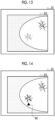
- Fig. 11 illustrates an example of the display state of the determination result.
- the display control unit 50 performs control to display a character string indicating the determination result by the determination unit 48 in the vicinity of the spicula candidate region to be determined.
- a character string "spicula” is displayed in the vicinity of the spicula candidate region determined to be the spicula.
- the spicula candidate region that does not have the character string displayed in the vicinity thereof means the "normal mammary gland".
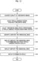
- the CPU 20 executes the image processing program 30 to perform the composite two-dimensional image generation process illustrated in Fig. 12 .
- the composite two-dimensional image generation process illustrated in Fig. 12 is performed, for example, in a case in which the user inputs an execution start instruction through the input device 24.
- Step S10 the acquisition unit 40 acquires a plurality of tomographic images Dj generated by the tomosynthesis imaging performed by the mammography apparatus 1 under the control of the console 2.
- Step S11 the detection unit 42 detects the spicula candidate region from each of the plurality of tomographic images Dj acquired in Step S10 (see Fig. 7 ).
- Step S12 the selection unit 44 selects a tomographic image group corresponding to the spicula candidate regions detected from the same position in the tomographic images Dj among the plurality of spicula candidate regions detected by the detection unit 42 in Step S11 (see Fig. 8 ).
- Step S13 the combination unit 46 generates the composite two-dimensional image SG using the tomographic image group selected by the selection unit 44 (see Figs. 8 and 9 ).
- Step S14 the determination unit 48 analyzes the composite two-dimensional image SG generated by the combination unit 46 to determine whether or not the spicula candidate region is the spicula (see Fig. 10 ).
- Step S15 the display control unit 50 performs control to display the composite two-dimensional image SG generated by the combination unit 46 on the display 23.
- Step S16 the display control unit 50 performs control to display the determination result of the spicula candidate region by the determination unit 48 on the display 23 (see Fig. 11 ).
- the composite two-dimensional image generation process ends.
- the tomographic image group corresponding to a plurality of spicula candidate regions detected from the same plane position in the tomographic images Dj are combined to generate the composite two-dimensional image SG. Therefore, in the composite two-dimensional image SG, the spicula candidate region has a radial shape in a case in which the spicula candidate region is the spicula and has a non-radial shape in a case in which the spicula candidate region is the normal mammary gland. Therefore, it is possible to accurately determine whether or not there is a spicula.
- the spicula candidate region is detected from the tomographic images. Therefore, it is possible to generate a composite two-dimensional image and to detect the spicula in a short processing time as compared to a case in which a candidate for, for example, a lesion is detected from a three-dimensional image (3D volume data) as in the related art. That is, according to this embodiment, it is possible to accurately detect the spicula in a short processing time. Therefore, a diagnostician, such as a doctor, need only interpret one composite two-dimensional image instead of the three-dimensional image. Therefore, an interpretation burden is reduced. In addition, the tomographic image that is no longer needed for interpretation is deleted from the storage device to save the capacity of the storage device.
- the display control unit 50 performs control to display the determination result by the determination unit 48 with a character string.
- the display control unit 50 may perform control to display the determination result by the determination unit 48 such that the color of the spicula candidate region indicating the determination result is different from the color of other regions.
- the spicula candidate region determined to be the spicula is displayed by a broken line. The broken line indicates the difference in color from other regions.
- the display control unit 50 may perform control to display a mark 60 indicating the determination result by the determination unit 48 in the vicinity of the spicula candidate region indicating the determination result.
- the triangular mark 60 is displayed in the vicinity of the spicula candidate region determined to be the spicula.
- the combination unit 46 uses the added average value of the pixel values at the corresponding pixel positions in the tomographic image group as the pixel value of the composite two-dimensional image SG.
- the combination unit 46 may use the added average value of the pixel values as the pixel value of the composite two-dimensional image SG. In the case of this combination, for the pixel at the pixel position included in only one of the plurality of spicula candidate regions, the combination unit 46 uses the pixel value of the pixel as the pixel value of the composite two-dimensional image SG.
- the combination unit 46 combines all of the tomographic images included in the tomographic image group selected by the selection unit 44. However, the combination unit 46 may combine some of the tomographic images included in the tomographic image group. For example, in the example illustrated in Fig. 8 , the combination unit 46 may combine only the tomographic image D2 and the tomographic image D4 among the tomographic images D2 to D4 included in the first tomographic image group P1. That is, the combination process of the combination unit 46 is not limited to the combination of a plurality of continuous tomographic images and may combine a plurality of discontinuous tomographic images.
- the detection unit 42 detects a region having a radial structure from the tomographic image as the spicula candidate region.
- the detection unit 42 may detect a region having a structure other than the radial structure as a lesion candidate region, in addition to the spicula candidate region having the radial structure.
- the combination unit 46 changes the number of tomographic images used for combination from the tomographic image group selected by the selection unit 44 according to the type of candidate region.
- the combination unit 46 selects a smaller number of tomographic images from the tomographic image group than that in a case in which the candidate region is the spicula candidate region and performs the combination process.
- the combination unit 46 performs the combination process using all or a plurality of tomographic images included in the tomographic image group in a case in which the candidate region is the spicula candidate region and performs the combination process using one of the tomographic images included in the tomographic image group in a case in which the candidate region is a tumor candidate region.
- the combination process is performed using a smaller number of tomographic images, namely one tomographic image, than that used in the spicula candidate regions.
- the present disclosure is not limited thereto.
- a weighted average value or a median value, a maximum value, or a minimum value of the pixel values of the corresponding pixels in the selected tomographic image group may be applied as the pixel value of the pixel of the composite two-dimensional image SG.
- a tomographic image having pixels in which a difference between the pixel value of a pixel of interest and an average value of the pixel values of all of the tomographic images in the tomographic image group is larger than a set value a tomographic image in which a dispersion value of the pixel values of a region of interest including the pixel of interest is larger than that in other regions, or a tomographic image having pixels detected by edge detection may be selectively combined.
- the determination unit 48 determines the spicula candidate region on the basis of the composite two-dimensional image SG.
- the determination unit 48 is not essential and may not be provided.
- the diagnostician such as the doctor, may perform the determination on the basis of the composite two-dimensional image SG displayed on the display 23.
- the following various processors can be used as a hardware structure of processing units performing various processes, such as the acquisition unit 40, the detection unit 42, the selection unit 44, the combination unit 46, the determination unit 48, and the display control unit 50.
- the various processors include, for example, a CPU which is a general-purpose processor executing software (programs) to function as various processing units as described above, a programmable logic device (PLD), such as a field programmable gate array (FPGA), which is a processor whose circuit configuration can be changed after manufacture, and a dedicated electric circuit, such as an application specific integrated circuit (ASIC), which is a processor having a dedicated circuit configuration designed to perform a specific process.
- PLD programmable logic device
- FPGA field programmable gate array
- ASIC application specific integrated circuit
- One processing unit may be configured by one of the various processors or a combination of two or more processors of the same type or different types (for example, a combination of a plurality of FPGAs or a combination of a CPU and an FPGA).
- a plurality of processing units may be configured by one processor.
- a first example of the configuration in which a plurality of processing units are configured by one processor is an aspect in which one processor is configured by a combination of one or more CPUs and software and functions as a plurality of processing units.
- a representative example of this aspect is a client computer or a server computer.
- a second example of the configuration is an aspect in which a processor that implements the functions of the entire system including a plurality of processing units using one integrated circuit (IC) chip is used.
- IC integrated circuit
- a representative example of this aspect is a system-on-chip (SoC).
- SoC system-on-chip
- various processing units are configured by using one or more of the various processors as a hardware structure.
- an electric circuit obtained by combining circuit elements, such as semiconductor elements, can be used as the hardware structure of the various processors.
- the image processing program 30 may be recorded on a recording medium, such as a compact disc read only memory (CD-ROM), a digital versatile disc read only memory (DVD-ROM), or a universal serial bus (USB) memory, and then provided.
- a recording medium such as a compact disc read only memory (CD-ROM), a digital versatile disc read only memory (DVD-ROM), or a universal serial bus (USB) memory
- the image processing program 30 may be downloaded from an external device through a network.
Landscapes
- Engineering & Computer Science (AREA)
- Health & Medical Sciences (AREA)
- Life Sciences & Earth Sciences (AREA)
- Medical Informatics (AREA)
- Physics & Mathematics (AREA)
- Nuclear Medicine, Radiotherapy & Molecular Imaging (AREA)
- General Health & Medical Sciences (AREA)
- Radiology & Medical Imaging (AREA)
- Computer Vision & Pattern Recognition (AREA)
- Heart & Thoracic Surgery (AREA)
- Veterinary Medicine (AREA)
- Pathology (AREA)
- High Energy & Nuclear Physics (AREA)
- Biomedical Technology (AREA)
- Biophysics (AREA)
- Molecular Biology (AREA)
- Surgery (AREA)
- Animal Behavior & Ethology (AREA)
- Optics & Photonics (AREA)
- Public Health (AREA)
- General Physics & Mathematics (AREA)
- Theoretical Computer Science (AREA)
- Quality & Reliability (AREA)
- Oral & Maxillofacial Surgery (AREA)
- Physiology (AREA)
- Dentistry (AREA)
- Bioinformatics & Cheminformatics (AREA)
- Bioinformatics & Computational Biology (AREA)
- Evolutionary Biology (AREA)
- Probability & Statistics with Applications (AREA)
- Apparatus For Radiation Diagnosis (AREA)
Claims (5)
- Bildverarbeitungsvorrichtung, umfassend:mindestens einen Prozessor (20),einen Speicher (21), der ein Programm speichert, das so konfiguriert ist, dass es den Prozessor veranlasst:aus jedem von mehreren Tomographiebildern (P1, P2), die mehrere Tomographieebenen eines Objekts angeben, einen Spicula-Kandidatenbereich, der eine Radiallinienstruktur aufweist, zu detektieren, mehrere der Tomographiebilder, die mehreren Spicula-Kandidatenbereichen, die die gleiche Radiallinienstruktur angeben, unter mehreren detektierten Spicula-Kandidatenbereichen entsprechen, als eine Tomographiebild-Gruppe auszuwählen, und ein zusammengesetztes zweidimensionales Bild unter Verwendung aller oder mehrerer der Tomographiebilder, die in der ausgewählten Tomographiebild-Gruppe enthalten sind, zu erzeugen, undwobei das Programm den Prozessor veranlasst, zusätzlich zu dem Spicula-Kandidatenbereich einen Läsionskandidatenbereich, der eine Struktur, die von der Radiallinienstruktur verschieden ist, aufweist, zu detektieren, undin einem Fall, in dem ein Kandidatenbereich nicht der Spicula-Kandidatenbereich ist, das Programm den Prozessor veranlasst, nur ein Tomographiebild aus den mehreren Tomographiebildern auszuwählen, um das zusammengesetzte zweidimensionale Bild zu erzeugen.
- Bildverarbeitungsvorrichtung nach Anspruch 1,
wobei das Programm den Prozessor veranlasst, das zusammengesetzte zweidimensionale Bild zu analysieren, um zu bestimmen, ob der Spicula-Kandidatenbereich ein Spicula ist oder nicht. - Bildverarbeitungsvorrichtung nach Anspruch 2,
wobei das Programm den Prozessor veranlasst, Steuerung zum Anzeigen des zusammengesetzten zweidimensionalen Bildes auf der Anzeige durchzuführen und Steuerung zum Anzeigen, auf der Anzeige, eines Ergebnisses des Bestimmens, ob der Spicula-Kandidatenbereich auf dem zusammengesetzten zweidimensionalen Bild das Spicula ist oder nicht, durchzuführen. - Bildverarbeitungsverfahren, das von einem Prozessor (20), der in einer Bildverarbeitungsvorrichtung (4) enthalten ist, ausgeführt wird, wobei das Bildverarbeitungsverfahren umfasst:Detektieren eines Spicula-Kandidatenbereichs, der eine Radiallinienstruktur aufweist, aus jedem von mehreren Tomographiebildern, die mehrere Tomographieebenen eines Objekts angeben;Auswählen von mehreren der Tomographiebilder, die mehreren der Spicula-Kandidatenbereichen, die die gleiche Radiallinienstruktur angeben, unter mehreren der detektierten Spicula-Kandidatenbereiche entsprechen, als eine Tomographiebild-Gruppe; undErzeugen eines zusammengesetzten zweidimensionalen Bildes unter Verwendung aller oder mehrerer der Tomographiebilder, die in der ausgewählten Tomographiebild-Gruppe enthalten sind; wobei das Bildverarbeitungsverfahren ferner umfasst:Detektieren, zusätzlich zu dem Spicula-Kandidatenbereich, eines Läsionskandidatenbereichs, der eine Struktur, die von der Radiallinienstruktur verschieden ist, aufweist, undin einem Fall, in dem ein Kandidatenbereich nicht der Spicula-Kandidatenbereich ist, Auswählen nur eines Tomographiebildes aus den mehreren Tomographiebildern, um das zusammengesetzte zweidimensionale Bild zu erzeugen.
- Computerlesbares Speichermedium, das ein Bildverarbeitungsprogramm speichert, das einen Prozessor, der in einer Bildverarbeitungsvorrichtung enthalten ist, veranlasst, einen Prozess auszuführen, der umfasst:Detektieren eines Spicula-Kandidatenbereichs, der eine Radiallinienstruktur aufweist, aus jedem von mehreren Tomographiebildern, die mehrere Tomographieebenen eines Objekts angeben;Auswählen von mehreren der Tomographiebilder, die mehreren der Spicula-Kandidatenbereichen, die die gleiche Radiallinienstruktur angeben, unter mehreren der detektierten Spicula-Kandidatenbereiche entsprechen, als eine Tomographiebild-Gruppe;Erzeugen eines zusammengesetzten zweidimensionalen Bildes unter Verwendung aller oder mehrerer der Tomographiebilder, die in der ausgewählten Tomographiebild-Gruppe enthalten sind;Detektieren, zusätzlich zu dem Spicula-Kandidatenbereich, eines Läsionskandidatenbereichs, der eine Struktur, die von der Radiallinienstruktur verschieden ist, aufweist, undin einem Fall, in dem ein Kandidatenbereich nicht der Spicula-Kandidatenbereich ist, Auswählen nur eines Tomographiebildes aus den mehreren Tomographiebildern, um das zusammengesetzte zweidimensionale Bild zu erzeugen.
Applications Claiming Priority (1)
| Application Number | Priority Date | Filing Date | Title |
|---|---|---|---|
| JP2021056178A JP7607489B2 (ja) | 2021-03-29 | 2021-03-29 | 画像処理装置、画像処理方法、及び画像処理プログラム |
Publications (2)
| Publication Number | Publication Date |
|---|---|
| EP4066744A1 EP4066744A1 (de) | 2022-10-05 |
| EP4066744B1 true EP4066744B1 (de) | 2025-06-11 |
Family
ID=80780498
Family Applications (1)
| Application Number | Title | Priority Date | Filing Date |
|---|---|---|---|
| EP22162213.7A Active EP4066744B1 (de) | 2021-03-29 | 2022-03-15 | Bildverarbeitungsvorrichtung, bildverarbeitungsverfahren und bildverarbeitungsprogramm |
Country Status (3)
| Country | Link |
|---|---|
| US (1) | US12536649B2 (de) |
| EP (1) | EP4066744B1 (de) |
| JP (1) | JP7607489B2 (de) |
Families Citing this family (1)
| Publication number | Priority date | Publication date | Assignee | Title |
|---|---|---|---|---|
| JP7542477B2 (ja) * | 2021-03-29 | 2024-08-30 | 富士フイルム株式会社 | 画像処理装置、画像処理方法、及び画像処理プログラム |
Family Cites Families (12)
| Publication number | Priority date | Publication date | Assignee | Title |
|---|---|---|---|---|
| CA2177472A1 (en) | 1993-11-29 | 1995-06-01 | Maryellen L. Giger | Automated method and system for improved computerized detection and classification of masses in mammograms |
| US7760924B2 (en) | 2002-11-27 | 2010-07-20 | Hologic, Inc. | System and method for generating a 2D image from a tomosynthesis data set |
| US9805507B2 (en) * | 2012-02-13 | 2017-10-31 | Hologic, Inc | System and method for navigating a tomosynthesis stack using synthesized image data |
| WO2013136222A2 (en) | 2012-03-12 | 2013-09-19 | Koninklijke Philips N.V. | Providing image information of an object |
| JP6506769B2 (ja) * | 2014-02-28 | 2019-04-24 | ホロジック, インコーポレイテッドHologic, Inc. | トモシンセシス画像スラブを生成し表示するためのシステムおよび方法 |
| US20170079604A1 (en) * | 2015-09-18 | 2017-03-23 | Anbinh T. Ho | System and method for digital breast tomosynthesis |
| EP3600047A1 (de) | 2017-03-30 | 2020-02-05 | Hologic, Inc. | System und verfahren zur hierarchischen mehrstufigen merkmalsbildsynthese und -darstellung |
| CN112770674B (zh) * | 2018-09-28 | 2024-08-06 | 豪洛捷公司 | 通过高密度元素抑制来合成乳腺组织的图像生成的系统和方法 |
| WO2020202612A1 (ja) * | 2019-03-29 | 2020-10-08 | 富士フイルム株式会社 | 画像処理装置、方法およびプログラム |
| JP7242436B2 (ja) * | 2019-06-13 | 2023-03-20 | 富士フイルム株式会社 | 読影支援装置、読影支援方法、及び読影支援プログラム |
| JP7203705B2 (ja) | 2019-09-17 | 2023-01-13 | 富士フイルム株式会社 | 画像処理装置、方法およびプログラム、並びに画像表示装置、方法およびプログラム |
| EP4101387B1 (de) | 2020-02-04 | 2024-07-17 | FUJIFILM Corporation | Bildeinstellvorrichtung, -verfahren und -programm |
-
2021
- 2021-03-29 JP JP2021056178A patent/JP7607489B2/ja active Active
-
2022
- 2022-02-28 US US17/683,254 patent/US12536649B2/en active Active
- 2022-03-15 EP EP22162213.7A patent/EP4066744B1/de active Active
Also Published As
| Publication number | Publication date |
|---|---|
| US20220309657A1 (en) | 2022-09-29 |
| US12536649B2 (en) | 2026-01-27 |
| JP2022153114A (ja) | 2022-10-12 |
| EP4066744A1 (de) | 2022-10-05 |
| JP7607489B2 (ja) | 2024-12-27 |
Similar Documents
| Publication | Publication Date | Title |
|---|---|---|
| US20230206397A1 (en) | Image processing device, method for operating image processing device, and program for operating image processing device | |
| US12488423B2 (en) | Image processing device, method for operating image processing device, and program for operating image processing device | |
| EP4066744B1 (de) | Bildverarbeitungsvorrichtung, bildverarbeitungsverfahren und bildverarbeitungsprogramm | |
| US20230267657A1 (en) | Image processing device, image processing method, image processing program, image display device, image display method, and image display program | |
| US12112479B2 (en) | Image processing device, image processing method, and image processing program | |
| US12272055B2 (en) | Image processing device, image processing method, and image processing program | |
| US12327352B2 (en) | Image setting device, image setting method, and image setting program | |
| US12419590B2 (en) | Image processing device, image processing method, and image processing program | |
| EP4528651A1 (de) | Bildverarbeitungsvorrichtung, radiographiesystem und programm | |
| EP4524891A1 (de) | Bildverarbeitungsvorrichtung, radiographiesystem und programm | |
| US20250285267A1 (en) | Image processing apparatus, radiography system, and program | |
| US20230146430A1 (en) | Image processing device, image processing method, and image processing program | |
| US12307664B2 (en) | Image processing device, image processing method, and image processing program | |
| US12597126B2 (en) | Image setting device, image setting method, and image setting program |
Legal Events
| Date | Code | Title | Description |
|---|---|---|---|
| PUAI | Public reference made under article 153(3) epc to a published international application that has entered the european phase |
Free format text: ORIGINAL CODE: 0009012 |
|
| STAA | Information on the status of an ep patent application or granted ep patent |
Free format text: STATUS: THE APPLICATION HAS BEEN PUBLISHED |
|
| AK | Designated contracting states |
Kind code of ref document: A1 Designated state(s): AL AT BE BG CH CY CZ DE DK EE ES FI FR GB GR HR HU IE IS IT LI LT LU LV MC MK MT NL NO PL PT RO RS SE SI SK SM TR |
|
| STAA | Information on the status of an ep patent application or granted ep patent |
Free format text: STATUS: REQUEST FOR EXAMINATION WAS MADE |
|
| 17P | Request for examination filed |
Effective date: 20230328 |
|
| RBV | Designated contracting states (corrected) |
Designated state(s): AL AT BE BG CH CY CZ DE DK EE ES FI FR GB GR HR HU IE IS IT LI LT LU LV MC MK MT NL NO PL PT RO RS SE SI SK SM TR |
|
| GRAP | Despatch of communication of intention to grant a patent |
Free format text: ORIGINAL CODE: EPIDOSNIGR1 |
|
| STAA | Information on the status of an ep patent application or granted ep patent |
Free format text: STATUS: GRANT OF PATENT IS INTENDED |
|
| INTG | Intention to grant announced |
Effective date: 20250127 |
|
| RAP3 | Party data changed (applicant data changed or rights of an application transferred) |
Owner name: FUJIFILM CORPORATION |
|
| GRAS | Grant fee paid |
Free format text: ORIGINAL CODE: EPIDOSNIGR3 |
|
| GRAA | (expected) grant |
Free format text: ORIGINAL CODE: 0009210 |
|
| STAA | Information on the status of an ep patent application or granted ep patent |
Free format text: STATUS: THE PATENT HAS BEEN GRANTED |
|
| P01 | Opt-out of the competence of the unified patent court (upc) registered |
Free format text: CASE NUMBER: APP_16501/2025 Effective date: 20250404 |
|
| AK | Designated contracting states |
Kind code of ref document: B1 Designated state(s): AL AT BE BG CH CY CZ DE DK EE ES FI FR GB GR HR HU IE IS IT LI LT LU LV MC MK MT NL NO PL PT RO RS SE SI SK SM TR |
|
| REG | Reference to a national code |
Ref country code: GB Ref legal event code: FG4D |
|
| REG | Reference to a national code |
Ref country code: CH Ref legal event code: EP |
|
| REG | Reference to a national code |
Ref country code: DE Ref legal event code: R096 Ref document number: 602022015701 Country of ref document: DE |
|
| REG | Reference to a national code |
Ref country code: IE Ref legal event code: FG4D |
|
| PG25 | Lapsed in a contracting state [announced via postgrant information from national office to epo] |
Ref country code: FI Free format text: LAPSE BECAUSE OF FAILURE TO SUBMIT A TRANSLATION OF THE DESCRIPTION OR TO PAY THE FEE WITHIN THE PRESCRIBED TIME-LIMIT Effective date: 20250611 Ref country code: ES Free format text: LAPSE BECAUSE OF FAILURE TO SUBMIT A TRANSLATION OF THE DESCRIPTION OR TO PAY THE FEE WITHIN THE PRESCRIBED TIME-LIMIT Effective date: 20250611 |
|
| REG | Reference to a national code |
Ref country code: LT Ref legal event code: MG9D |
|
| PG25 | Lapsed in a contracting state [announced via postgrant information from national office to epo] |
Ref country code: GR Free format text: LAPSE BECAUSE OF FAILURE TO SUBMIT A TRANSLATION OF THE DESCRIPTION OR TO PAY THE FEE WITHIN THE PRESCRIBED TIME-LIMIT Effective date: 20250912 Ref country code: NO Free format text: LAPSE BECAUSE OF FAILURE TO SUBMIT A TRANSLATION OF THE DESCRIPTION OR TO PAY THE FEE WITHIN THE PRESCRIBED TIME-LIMIT Effective date: 20250911 |
|
| REG | Reference to a national code |
Ref country code: NL Ref legal event code: MP Effective date: 20250611 |
|
| PG25 | Lapsed in a contracting state [announced via postgrant information from national office to epo] |
Ref country code: BG Free format text: LAPSE BECAUSE OF FAILURE TO SUBMIT A TRANSLATION OF THE DESCRIPTION OR TO PAY THE FEE WITHIN THE PRESCRIBED TIME-LIMIT Effective date: 20250611 |
|
| PG25 | Lapsed in a contracting state [announced via postgrant information from national office to epo] |
Ref country code: HR Free format text: LAPSE BECAUSE OF FAILURE TO SUBMIT A TRANSLATION OF THE DESCRIPTION OR TO PAY THE FEE WITHIN THE PRESCRIBED TIME-LIMIT Effective date: 20250611 |
|
| PG25 | Lapsed in a contracting state [announced via postgrant information from national office to epo] |
Ref country code: RS Free format text: LAPSE BECAUSE OF FAILURE TO SUBMIT A TRANSLATION OF THE DESCRIPTION OR TO PAY THE FEE WITHIN THE PRESCRIBED TIME-LIMIT Effective date: 20250911 |
|
| PG25 | Lapsed in a contracting state [announced via postgrant information from national office to epo] |
Ref country code: LV Free format text: LAPSE BECAUSE OF FAILURE TO SUBMIT A TRANSLATION OF THE DESCRIPTION OR TO PAY THE FEE WITHIN THE PRESCRIBED TIME-LIMIT Effective date: 20250611 |
|
| PG25 | Lapsed in a contracting state [announced via postgrant information from national office to epo] |
Ref country code: NL Free format text: LAPSE BECAUSE OF FAILURE TO SUBMIT A TRANSLATION OF THE DESCRIPTION OR TO PAY THE FEE WITHIN THE PRESCRIBED TIME-LIMIT Effective date: 20250611 |
|
| PG25 | Lapsed in a contracting state [announced via postgrant information from national office to epo] |
Ref country code: PT Free format text: LAPSE BECAUSE OF FAILURE TO SUBMIT A TRANSLATION OF THE DESCRIPTION OR TO PAY THE FEE WITHIN THE PRESCRIBED TIME-LIMIT Effective date: 20251013 |
|
| REG | Reference to a national code |
Ref country code: AT Ref legal event code: MK05 Ref document number: 1801738 Country of ref document: AT Kind code of ref document: T Effective date: 20250611 |
|
| PG25 | Lapsed in a contracting state [announced via postgrant information from national office to epo] |
Ref country code: IS Free format text: LAPSE BECAUSE OF FAILURE TO SUBMIT A TRANSLATION OF THE DESCRIPTION OR TO PAY THE FEE WITHIN THE PRESCRIBED TIME-LIMIT Effective date: 20251011 |
|
| PG25 | Lapsed in a contracting state [announced via postgrant information from national office to epo] |
Ref country code: AT Free format text: LAPSE BECAUSE OF FAILURE TO SUBMIT A TRANSLATION OF THE DESCRIPTION OR TO PAY THE FEE WITHIN THE PRESCRIBED TIME-LIMIT Effective date: 20250611 Ref country code: SM Free format text: LAPSE BECAUSE OF FAILURE TO SUBMIT A TRANSLATION OF THE DESCRIPTION OR TO PAY THE FEE WITHIN THE PRESCRIBED TIME-LIMIT Effective date: 20250611 |
|
| PG25 | Lapsed in a contracting state [announced via postgrant information from national office to epo] |
Ref country code: CZ Free format text: LAPSE BECAUSE OF FAILURE TO SUBMIT A TRANSLATION OF THE DESCRIPTION OR TO PAY THE FEE WITHIN THE PRESCRIBED TIME-LIMIT Effective date: 20250611 |
|
| PG25 | Lapsed in a contracting state [announced via postgrant information from national office to epo] |
Ref country code: PL Free format text: LAPSE BECAUSE OF FAILURE TO SUBMIT A TRANSLATION OF THE DESCRIPTION OR TO PAY THE FEE WITHIN THE PRESCRIBED TIME-LIMIT Effective date: 20250611 |
|
| PG25 | Lapsed in a contracting state [announced via postgrant information from national office to epo] |
Ref country code: EE Free format text: LAPSE BECAUSE OF FAILURE TO SUBMIT A TRANSLATION OF THE DESCRIPTION OR TO PAY THE FEE WITHIN THE PRESCRIBED TIME-LIMIT Effective date: 20250611 |
|
| PG25 | Lapsed in a contracting state [announced via postgrant information from national office to epo] |
Ref country code: SK Free format text: LAPSE BECAUSE OF FAILURE TO SUBMIT A TRANSLATION OF THE DESCRIPTION OR TO PAY THE FEE WITHIN THE PRESCRIBED TIME-LIMIT Effective date: 20250611 |
|
| REG | Reference to a national code |
Ref country code: DE Ref legal event code: R097 Ref document number: 602022015701 Country of ref document: DE |
|
| PG25 | Lapsed in a contracting state [announced via postgrant information from national office to epo] |
Ref country code: DK Free format text: LAPSE BECAUSE OF FAILURE TO SUBMIT A TRANSLATION OF THE DESCRIPTION OR TO PAY THE FEE WITHIN THE PRESCRIBED TIME-LIMIT Effective date: 20250611 |
|
| PGFP | Annual fee paid to national office [announced via postgrant information from national office to epo] |
Ref country code: DE Payment date: 20260128 Year of fee payment: 5 |
|
| PG25 | Lapsed in a contracting state [announced via postgrant information from national office to epo] |
Ref country code: IT Free format text: LAPSE BECAUSE OF FAILURE TO SUBMIT A TRANSLATION OF THE DESCRIPTION OR TO PAY THE FEE WITHIN THE PRESCRIBED TIME-LIMIT Effective date: 20250611 |
|
| PLBE | No opposition filed within time limit |
Free format text: ORIGINAL CODE: 0009261 |
|
| STAA | Information on the status of an ep patent application or granted ep patent |
Free format text: STATUS: NO OPPOSITION FILED WITHIN TIME LIMIT |
|
| REG | Reference to a national code |
Ref country code: CH Ref legal event code: L10 Free format text: ST27 STATUS EVENT CODE: U-0-0-L10-L00 (AS PROVIDED BY THE NATIONAL OFFICE) Effective date: 20260423 |